EP3513511B1 - Method and apparatus for uplink transmission - Google Patents
Method and apparatus for uplink transmission Download PDFInfo
- Publication number
- EP3513511B1 EP3513511B1 EP18773708.5A EP18773708A EP3513511B1 EP 3513511 B1 EP3513511 B1 EP 3513511B1 EP 18773708 A EP18773708 A EP 18773708A EP 3513511 B1 EP3513511 B1 EP 3513511B1
- Authority
- EP
- European Patent Office
- Prior art keywords
- transmission
- configuration
- terminal device
- mode
- network node
- Prior art date
- Legal status (The legal status is an assumption and is not a legal conclusion. Google has not performed a legal analysis and makes no representation as to the accuracy of the status listed.)
- Active
Links
- 230000005540 biological transmission Effects 0.000 title claims description 203
- 238000000034 method Methods 0.000 title claims description 46
- 238000004891 communication Methods 0.000 claims description 52
- 239000000969 carrier Substances 0.000 claims description 22
- 238000004590 computer program Methods 0.000 claims description 11
- 230000015654 memory Effects 0.000 claims description 11
- 230000004044 response Effects 0.000 claims description 9
- 238000010586 diagram Methods 0.000 description 18
- 230000011664 signaling Effects 0.000 description 10
- 230000000737 periodic effect Effects 0.000 description 9
- 230000008901 benefit Effects 0.000 description 8
- 238000012545 processing Methods 0.000 description 8
- 238000013507 mapping Methods 0.000 description 5
- 238000003491 array Methods 0.000 description 4
- 230000006870 function Effects 0.000 description 4
- 230000001960 triggered effect Effects 0.000 description 4
- 238000007726 management method Methods 0.000 description 3
- 238000005259 measurement Methods 0.000 description 3
- 230000008569 process Effects 0.000 description 3
- 238000013468 resource allocation Methods 0.000 description 3
- 239000007787 solid Substances 0.000 description 3
- 230000008859 change Effects 0.000 description 2
- 238000012986 modification Methods 0.000 description 2
- 230000004048 modification Effects 0.000 description 2
- 238000012544 monitoring process Methods 0.000 description 2
- 230000035945 sensitivity Effects 0.000 description 2
- 230000006978 adaptation Effects 0.000 description 1
- 230000003139 buffering effect Effects 0.000 description 1
- 230000001413 cellular effect Effects 0.000 description 1
- 238000011161 development Methods 0.000 description 1
- 230000000694 effects Effects 0.000 description 1
- 238000000605 extraction Methods 0.000 description 1
- 230000007774 longterm Effects 0.000 description 1
- 230000007246 mechanism Effects 0.000 description 1
- 230000003287 optical effect Effects 0.000 description 1
- 238000012546 transfer Methods 0.000 description 1
- 230000003245 working effect Effects 0.000 description 1
Images


Classifications
-
- H—ELECTRICITY
- H04—ELECTRIC COMMUNICATION TECHNIQUE
- H04W—WIRELESS COMMUNICATION NETWORKS
- H04W72/00—Local resource management
- H04W72/20—Control channels or signalling for resource management
- H04W72/21—Control channels or signalling for resource management in the uplink direction of a wireless link, i.e. towards the network
-
- H—ELECTRICITY
- H04—ELECTRIC COMMUNICATION TECHNIQUE
- H04W—WIRELESS COMMUNICATION NETWORKS
- H04W72/00—Local resource management
- H04W72/20—Control channels or signalling for resource management
- H04W72/23—Control channels or signalling for resource management in the downlink direction of a wireless link, i.e. towards a terminal
-
- H—ELECTRICITY
- H04—ELECTRIC COMMUNICATION TECHNIQUE
- H04W—WIRELESS COMMUNICATION NETWORKS
- H04W72/00—Local resource management
- H04W72/12—Wireless traffic scheduling
- H04W72/1263—Mapping of traffic onto schedule, e.g. scheduled allocation or multiplexing of flows
- H04W72/1268—Mapping of traffic onto schedule, e.g. scheduled allocation or multiplexing of flows of uplink data flows
-
- H—ELECTRICITY
- H04—ELECTRIC COMMUNICATION TECHNIQUE
- H04W—WIRELESS COMMUNICATION NETWORKS
- H04W76/00—Connection management
- H04W76/20—Manipulation of established connections
- H04W76/27—Transitions between radio resource control [RRC] states
Description
- The present disclosure generally relates to wireless communications, and more specifically, to uplink transmission.
- This section introduces aspects that may facilitate a better understanding of the disclosure. Accordingly, the statements of this section are to be read in this light and are not to be understood as admissions about what is in the prior art or what is not in the prior art.
- In wireless communication system, a Scheduling Request (SR) is sent from a terminal device to network side, asking for uplink resource for communication, according to the instruction of configuration on SR transmission. In the discussion on next generation communication system such as 5G or new radio (NR), it is agreed that more than one SR configuration can be configured for a terminal device. A Logical Channel (LCH) can be mapped to a separate SR configuration, so that a network node can identify the LCH that trigger a SR upon reception of the SR.
- In recent 3GPP discussion, it was agreed that an SR configuration may consists of a set of Physical Uplink Control Channel (PUCCH) resources. In other words, multiple SR signals can be transmitted in different frequency resources for a same SR trigger event. However, there is no signaling details on how to configure SR transmission under the agreed frame.
-
US 2013/163537 A1 describes a method of sending and receiving scheduling requests within wireless communication system, wherein a method implemented in a user equipment UE for single carrier frequency division multiple access SC-FDMA within a wireless system comprises receiving an assignment of a plurality of uplink scheduling request resources and comprising a plurality of SC-FDMA subcarriers of the wireless system; selecting one of the plurality of uplink scheduling request resources for transmission of scheduling requests; determining that a change in uplink scheduling request resource should be made; and upon determining that a change in scheduling request resource should be made, selecting another of the assigned uplink scheduling request resources for transmission of scheduling requests. -
WO 2016/185895 A1 describes an uplink transmission procedure from a UE to a eNB. A method of associating the "SR w/BSR" with the "LCG ID" is described, wherein the UE transmits the "SR w/BSR" in association with the "LCG ID". - The 3GPP Draft "On low latency Scheduling Request", R1-1704756, XP051242894, 2 April 2017, describes aspects of URLLC scheduling request operation focusing or low latency considerations. For grant-based UL URLLC, the scheduling request transmission may become a bottleneck in overall latency if its transmission is unreliable. The main mechanisms to improve its reliability could be extraction of diversity and possible enabling of repetitions.
- The invention is defined in the appended set of claims. This summary is provided to introduce a selection of concepts in a simplified form that are further described below in detailed description. This summary is not intended to identify key features or essential features of the claimed subject matter, nor is it intended to be used to limit the scope of the claimed subject matter.
- By means of the solutions set forth in the above aspects of the present disclosure and those as discussed hereinafter, SR transmission diversity with efficient signaling can be achieved.
- The disclosure itself, the preferable mode of use and further objectives are best understood by reference to the following detailed description of the embodiments when read in conjunction with the accompanying drawings, in which:
-
Fig.1 illustrates an exemplary flow diagram for asking uplink resource process in a terminal device according to one or more embodiments of the present disclosure; -
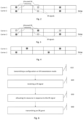
Figs.2-4 are diagrams illustrating examples of resource allocation on SR signaling corresponding to a SR transmission diversity mode according to some embodiments of the present disclosure; -
Fig.2 is also a diagram illustrating an example of SR duplicated transmission across carriers based on allocated SR resources according to one or more embodiments of the present disclosure; -
Fig.3 is also a diagram illustrating an example of SR transmission switching across carriers based on allocated SR resources according to an embodiment of the present disclosure; -
Fig.4 is a diagram illustrating an example of SR resource allocation across carriers corresponding to a SR transmission diversity mode according to an embodiment of the present disclosure; -
Fig.5 is a diagram illustrating examples of a UE asking for uplink resource from a gNB through SR signaling according to an embodiment of the present disclosure; -
Fig. 6 illustrates an exemplary flow diagram for uplink resource management process in a network node according to one or more embodiments of the present disclosure; -
Fig.7 is a block diagram illustrating an apparatus according to one or more embodiments of the present disclosure; -
Fig.8 is a block diagram illustrating an apparatus according to one or more embodiments of the present disclosure; -
Fig. 9 is a block diagram illustrating an apparatus according to one or more embodiments of the present disclosure; -
Fig. 10 schematically illustrates a telecommunication network connected via an intermediate network to a host computer; -
Figure 11 is a generalized block diagram of a host computer communicating via a base station with a user equipment over a partially wireless connection; -
Figures 12 and 13 are flowcharts illustrating methods implemented in a communication system including a host computer, a base station and a user equipment. - The embodiments of the present disclosure are described in detail with reference to the accompanying drawings. It should be understood that these embodiments are discussed only for the purpose of enabling those skilled persons in the art to better understand and thus implement the present disclosure, rather than suggesting any limitations on the scope of the present disclosure. Reference throughout this specification to features, advantages, or similar language does not imply that all of the features and advantages that may be realized with the present disclosure should be or are in any single embodiment of the disclosure. Rather, language referring to the features and advantages is understood to mean that a specific feature, advantage, or characteristic described in connection with an embodiment is included in at least one embodiment of the present disclosure. Furthermore, the described features, advantages, and characteristics of the disclosure may be combined in any suitable manner in one or more embodiments. One skilled in the relevant art will recognize that the disclosure may be practiced without one or more of the specific features or advantages of a particular embodiment. In other instances, additional features and advantages may be recognized in certain embodiments that may not be present in all embodiments of the disclosure.
- As used herein, the term "wireless communication network" refers to a network following any suitable communication standards, such as Next Radio (NR), long term evolution-advanced (LTE-A), LTE, wideband code division multiple access (WCDMA), high-speed packet access (HSPA), and so on. Furthermore, the communications between a terminal device and a network node in the wireless communication network may be performed according to any suitable generation communication protocols, including, but not limited to, the fourth generation (4G), 4.5G, the fifth generation (5G) communication protocols, and/or any other protocols either currently known or to be developed in the future.
- The term "network node" refers to a network device in a wireless communication network via which a terminal device accesses to the network and receives services therefrom. The network device refers to a base station (BS), an access point (AP), a mobile management entity (MME), multi-cell/multicast coordination entity (MCE), a gateway, a server, a controller or any other suitable device in the wireless communication network. The BS may be, for example, a node B (NodeB or NB), an evolved NodeB (eNodeB or eNB), a next generation NodeB (gNodeB or gNB), a remote radio unit (RRU), a radio header (RH), a remote radio head (RRH), a relay, a low power node such as a femto, a pico, and so forth.
- The term "terminal device" refers to any end device that can access a wireless communication network and receive services therefrom. By way of example and not limitation, in an internet of things (IoT) scenario, the terminal device may represent a machine or other device that performs monitoring and/or measurements, and transmits the results of such monitoring and/or measurements to another terminal device and/or a network equipment. The terminal device may in this case be a machine-to-machine (M2M) device, which may in a 3GPP context be referred to as a machine-type communication (MTC) device.
- The terminal device may also refer to a mobile terminal, user equipment (UE), or other suitable devices. The UE may be, for example, a subscriber station, a portable subscriber station, a mobile station (MS) or an access terminal (AT). The terminal device may include, but not limited to, portable computers, image capture terminal devices such as digital cameras, gaming terminal devices, music storage and playback appliances, and the like.
- The terminal device may support device-to-device (D2D) communication, for example by implementing a 3GPP standard for sidelink communication, and may in this case be referred to as a D2D communication device.
- As used herein, the terms "first", "second" and so forth refer to different elements. The singular forms "a" and "an" are intended to include the plural forms as well, unless the context clearly indicates otherwise. The terms "comprises", "comprising", "has", "having", "includes" and/or "including" as used herein, specify the presence of stated features, elements, and/or components and the like, but do not preclude the presence or addition of one or more other features, elements, components and/or combinations thereof. The term "according to" is to be read as "at least in part according to". The term "one embodiment" and "an embodiment" are to be read as "at least one embodiment". The term "another embodiment" is to be read as "at least one other embodiment". Other definitions, explicit and implicit, may be included below.
- Wireless communication networks are widely deployed to provide various telecommunication services such as voice, video, data, messaging and broadcasts. A terminal device can be supplied with multiple types of services, even simultaneously. A service type corresponds to a Logic Channel Group (LCG) which consists of one or more Logic Channels (LCHs). For example, a media stream transmission may need two LCHs for audio and video transmission, separately. An SR configuration corresponds a service type provided by the wireless communication networks, which comprises a set of parameters which can be used to determine its associated SR resources, such as transmission periods and offsets of PUCCH occurrences, time-frequency resources, and power control parameters for PUCCH transmissions.
- To meet dramatically increasing network requirements on delay sensitivity, one interesting option for communication technique development is to allow an SR configuration to comprise a collection of sets of PUCCH resources in a wireless communication network such as a NR or 5G system.
- The present disclosure provides an embodiment in a wireless communication network, shown in
Fig. 1 , wherein a terminal device:
determines (120) SR transmission mode according to an obtained configuration on SR transmission corresponding to a Logic Channel Group (LCG); and transmits (130) at least one SR signal to a network node according to the determined SR transmission mode, asking for uplink grant for uplink transmission. - In the present disclosure, a SR transmission mode represents how SR signal is transmitted for uplink permission. According to some exemplary embodiments, a SR transmission mode can represent a single SR transmission. Periodic PUCCH resource, for example in every N subframe(s), is configured on one carrier for SR transmission, mapping onto a LCH or LCG. When an SR event is triggered, a terminal device transmits a SR signal on one of the periodic PUCCH resources which belong to a same carrier. A terminal device may further transmit more SR signals on more periodic PUCCH resources which belong to a same carrier, in case that an uplink grant is not received after the first SR is sent.
- An SR transmission mode can be an SR transmission diversity mode. Periodic PUCCH resources corresponding to a specific service are configured on a plurality of carriers for SR transmission. An SR transmission diversity mode can represent an SR duplicated transmission across carriers or an SR transmission switching across carriers.
-
Fig. 2 and Fig. 3 are diagrams illustrating examples of SR transmission diversity mode. InFig. 2 and Fig. 3 , PUCCH resources allocated for SR duplicated transmission can be found in bothcarrier 1 andcarrier 2. Each block in X-axis represents a subframe and it is only for simplicity that periodic PUCCH resources are allocated in every two subframes as an example.Fig. 2 illustrates an example of SR duplicated transmission. When an SR event is triggered, for example a service is initiated, two SR signals are both sent on PUCCH resources incarrier carrier -
Fig. 3 illustrates an example of SR transmission switching. When a SR event is triggered, an SR signal is sent on PUCCH resource incarrier 1 at the first subframe shown in the figure. In case that no granted resource is received, an SR signal is sent on PUCCH resource incarrier 2 at a next subframe with PUCCH resource, for example the third subframe shown in the figure. SR transmission is switched between carriers instead of remaining in a single carrier, so that it would be easier for the network node to receive SR signal than it is in single SR transmission scenario. Compared to SR transmission switching across carriers, SR duplicated transmission would be more suitable for delay sensitive service, however, its signal overhead is more than that of SR transmission switching. Therefore, SR transmission switching across carriers would be a balance between delay sensitivity and signal overhead. By choosing different SR transmission mode, a terminal device can satisfy different service requirement with efficient signaling. - It is noted that PUCCH resource for SR transmission illustrated in
Fig. 2 and Fig. 3 is just exemplary scenario. As another example, PUCCH resources allocated for SR transmission switching can only be the dotted blocks shown inFig.3 in which the SR signals are transmitted. In another exemplary scenario, PUCCH resources allocated for SR transmission in separate carriers can have distinguished periodic appearance. For example, there are one SR resource allocated incarrier 1 at every four subframes, and one SR resource allocated incarrier 2 at every two subframes. In another exemplary scenario, PUCCH resources allocated for SR transmission in different carriers are not necessarily align in time domain. As is shown inFig. 4 , staggered solid blocks are allocated for PUCCH resource for SR transmission. Solid blocks at the first and second subframes, incarrier 2 andcarrier 1 respectively, can be utilized for a SR duplicated transmission. - In an exemplary embodiment shown in
Fig. 5 , an SR transmission mode is firstly determined (520) by a User Equipment (UE) as a single SR transmission mode (SR mode 1), according to an obtained configuration on SR transmission. There would be multiple configurations on SR transmission mode obtained in the UE, corresponding to multiple types of services the communication networks can provide. An SR trigger event may be a service desired by the UE, then a LCG corresponding to the desired service would be used by the UE to select a configuration on SR transmission to which the LCG is mapped. In some circumstance, the LCG corresponding to the desired service consists of one LCH. - After the single SR transmission mode is determined, the UE sends a SR signal (530) to a gNB, asking for uplink resource. However, the SR signal fails to reach the gNB thus no response is heard. The UE sends a second SR signal to the gNB and then still gets no feedback.
- According to the configuration on SR transmission, the UE decides to continue determining its SR transmission mode, since a predefined time of SR transmission on
mode 1 had been performed till no feedback is got. The predefined time is 2 in this exemplary embodiment. The UE determines (540) a SR transmission diversity mode (SR mode 2) to substitute the single SR transmission mode. In other words, the determined SR transmission mode changes from a single SR transmission mode to a SR transmission diversity mode. - In an example, after UE determines a SR duplicated transmission across carriers as the SR transmission diversity mode, it sends (550) an SR signal separately in
carrier 1 andcarrier 2, i.e. on different PUCCHs, as shown inFig. 2 . At least one of the SR signals is received by the gNB, and then recognized by the gNB for the specific SR resource assigned to the specific UE. The gNB allocates (560) uplink resource and sends (570) a Scheduling Grant to the UE. - In another example, after UE determines a SR transmission switching across carriers as the SR transmission diversity mode, it sends (550) a SR signal in
carrier 1, then another SR signal incarrier 2, i.e. in different resource blocks as shown inFig.3 . Sincecarrier 2 has better communication quality thancarrier 1, the second SR signal is received and handled (560) by the gNB. As a result, a Scheduling Grant is received by the UE to allocate uplink resource for PUSCH transmission. -
Fig. 5 would illustrate another exemplary embodiment.SR mode 1 is determined (520) as a SR transmission switching mode in a UE, according to a selected SR transmission configuration corresponding to a LCG mapping to a desired service. After SR signals has been transmitted (530) for a predefined time, no feedback is received by the UE. Then the UE would make a second determination on SR transmission mode according to the configuration on SR transmission, thus SR duplicated transmission mode (mode 2) is determined (540). A plurality of SR signals is transmitted (550) by the UE and at least one of them successfully arrives at the gNB. The gNB makes (560) an uplink resource allocation and then sends (570) a SR grant to the UE. -
Fig. 5 would illustrate another exemplary embodiment. Due to a desired service requires very limited delay,SR mode 1 is determined (520) as a SR duplicated transmission mode in a UE, according to a selected SR transmission configuration corresponding to a LCG mapping to the service. A gNB receives (560) at least one of the SR signals and sends (570) SR grant to the UE. In this exemplary embodiment, there is neither second determination on SR transmission mode nor continued SR transmission after the second determination, which readers can find theblock 540 andarrows 540 inFig. 5 are drawn with dotted lines. - From above exemplary embodiments, a configuration on SR transmission may include information on a LCG corresponding to a service provided by the communication network. A possible implementation is to include a list of LCH IDs (LCIDs) in the configuration on SR transmission, the corresponding LCHs belonging to the LCG. Another possible implementation further reducing signal overhead, a bitmap for the LCHs is included as the information on the LCG. Each bit in the bitmap indicates the corresponding LCH, the bit position matching with the LCID or the LCH priority. SR resources (i.e. PUCCH resources) are also included in the configuration on SR transmission.
- A configuration on SR transmission may also include limited time for SR transmission regarding a SR transmission mode. As described above, a first predefined time is set for single SR transmission mode, for a threshold of whether to switch to a SR transmission diversity mode. Similarly, a second predefined time can be set for SR transmission diversity mode (which is not necessarily switched from single SR transmission mode). If there is no SR grant received after the second predefined time, UE may apply uplink resource through contention-based random access procedure.
- Instead of the second predefined time of SR transmission, a predefined period is also provided herein as a link adaption scheme by introducing a timer. The timer starts to count when SR transmission diversity mode is determined, or when SR transmissions are performed according to a SR transmission diversity mode. When the timer expires, the SR transmission mode is determined as single SR transmission mode. In other words, SR transmission diversity is disabled. The timer is for buffering the always-changing channel quality. Such scheme can adaptively adjust the SR transmission diversity without additional signaling overhead.
- Therefore, a configuration on SR transmission regarding a provided service may comprise one or more SR transmission modes. It could be a SR transmission diversity mode, or two or more SR transmission modes, and a condition that the UE would switch from one mode to another once the condition is satisfied.
- Instead of explicit indication on SR transmission mode is included in a configuration on SR transmission, for example, by SR transmission mode index, an indicator on whether SR diversity mode is enable or disabled can be included in another exemplary embodiment. Specifically, in an example, an indication of SR transmission diversity being enabled is included in a configuration on SR transmission. PUCCH resources on different carriers are allocated for the UE for SR transmission. In another example, an indication of SR transmission diversity being disabled by default is included, as well as a condition for the UE to enable its SR transmission diversity mode. The condition can be a predefined time that the UE sends SR signals, or a preset period that the UE sends SR signals to the gNB.
- According to an exemplary embodiment, the obtained (510) configuration on SR transmission can have difference sources. In an example, a terminal device obtains the configuration on SR transmission through a Radio Resource Control (RRC) message from a network node. For example, an Information Element (IE) included in an RRC message such as SchedulingRequestConfig indicates periodic resources for SR transmission for specific terminal device, so that the network node can identify the specific terminal device through one of the indicated resources for SR transmission, upon receipt of an SR signal.
- In another example, the terminal device obtains the configuration on SR transmission through a Physical Downlink Control Channel (PDCCH) order or Media Access Control (MAC) Control Element (CE) message from the network node. Compared to the semi-static RRC message indicating configuration on SR transmission mentioned above, PCDDH order or MAC CE message would be dynamically sent to the terminal device, reflecting the network node's determination on resource control. According to the examples described above, an obtaining step which is not shown in
Fig. 1 can be further comprised in a method embodiment. - In another example, the configuration on SR transmission is predefined or preconfigured in the terminal device. In a further exemplary embodiment, an RRC message indicating a configuration on SR transmission is sent to a terminal device which is preconfigured with a configuration on SR transmission. Furthermore, the terminal device would receive a PDCCH order indicating a configuration on SR transmission. In that case, the terminal device determines its SR transmission mode according to the latest obtained configuration.
- In the exemplary embodiment regarding the obtaining of configuration on SR transmission, not only SR resources are indicated in the configuration, but corresponding SR transmission mode(s). In an example, a terminal device can obtain different configurations on SR transmission mode through different resources. A predetermined configuration on SR transmission regarding a LCG is a single SR transmission mode, and SR resources in a carrier at periodic subframes. In other words, SR transmission diversity mode is disabled by default. A PDCCH order carrying a configuration on SR transmission regarding another LCG is obtained by the terminal device, indicating a SR duplicated transmission mode and SR resources across carriers at periodic subframes. In other words, SR duplicated transmission mode is enabled by the PDCCH order. When the terminal device is triggered by an SR event corresponding to the other LCG, more than one SR signals on different carriers are sent to the network node, according to the SR duplicated transmission mode. Those skilled in the art would easily think of analogical examples in which SR transmission switching mode is involved.
- In yet another exemplary embodiment, a method implemented by a network node is provided herein for uplink transmission management. The method comprises:
- transmitting (510, 610) a configuration on Scheduling Request, SR, transmission mode corresponding to a LCG, to a terminal device;
- receiving (620) a SR signal from the terminal device;
- allocating (560, 630) uplink resource in response to the received SR signal; and
- transmitting (570, 640) an SR grant to the terminal device.
- According to aforementioned embodiments, the configuration corresponding to the LCG can be transmitted through RRC message. Alternatively, the configuration corresponding the LCG representing a service type can be carried through a PDCCH order, or a MAC CE. The network node can analyze channel quality, such as path loss, interference and coding scheme, at least partially based on measurement report from terminal devices, then determine a configuration on SR transmission corresponding to the channel. The configuration information corresponding to the LCG in a PDCCH order or MAC CE can also override an existing configuration on SR transmission indicated in a previous RRC message, PDCCH order or MAC CE.
- The proposed solution according to one or more exemplary embodiments can enable a network node such as a gNB to configure a specific UE with an SR transmission configuration mapping on an LCG which corresponding to specific type of provided service. When it is foreseen that single SR transmission mode is hard to meet the requirement of transmission reliability, the network node can dynamically configure the terminal device to switch to an SR diversity mode in which allocated PUCCH resources in carriers for SR transmission would be concurrently or subsequently utilized in time domain. SR transmission diversity can be achieved with efficient signaling overhead. With the obtained SR transmission configuration, a UE can determine an appropriate SR transmission mode for the desired service. If transmission delay is more concerned than signaling overhead, a SR transmission diversity mode might be set as default mode. If signaling overhead is also important, single SR transmission mode might be selected first. Then a SR transmission diversity mode might be enabled when no uplink granted is received.
- Correspondingly, with received SR signals, a network node assigns different processes according to different required services. For example, the network node first assigns the resources to the LCHs mapping to Ultra Reliable and Low Latency Communication (URLLC) service. In such a case, scheduling delay for LCHs can be shortened especially with strict latency requirements.
- The various blocks shown in
Fig.1 andFig.5-6 may be viewed as method steps, and/or as operations that result from operation of computer program code, and/or as a plurality of coupled logic circuit elements constructed to carry out the associated function(s). The flow chart diagrams described above are generally set forth as logical flow chart diagrams. As such, the depicted order and labeled steps are indicative of specific embodiments of the presented methods. Other steps and methods may be conceived that are equivalent in function, logic, or effect to one or more steps, or portions thereof, of the illustrated methods. -
Fig.7 is a block diagram illustrating an apparatus according to various embodiments of the present disclosure. Specifically, an apparatus (700) may comprise one or more processors such as processor (701) and one or more memories such as memory (702) storing computer program codes (703). The memory (702) may be non-transitory machine/processor/computer readable storage medium. In some implementations, the one or more memories (702) and the computer program codes (703) may be configured to, with the one or more processors (701), cause the apparatus (700) at least to perform any operation of the method as described in connection withFig.1 and Fig.5 . - In other implementations, the one or more memories (702) and the computer program codes (703) in
Fig. 7 may be configured to, with the one or more processors (701), cause the apparatus (700) at least to perform any operation of the method as described in connection withFig. 5 andFig.6 . - Alternatively or additionally, the one or more memories 1102 and the computer program codes 1103 may be configured to, with the one or more processors 1101, cause the apparatus 1100 at least to perform more or less operations to implement the proposed methods according to the exemplary embodiments of the present disclosure.
-
Fig. 8 is a block diagram illustrating an apparatus (800) according to another embodiment of the present disclosure. As shown inFig.8 , the apparatus (800) may comprise a determining unit (801) and a transmitting unit (802). In an exemplary embodiment, the apparatus (800) may be implemented at a terminal device such as a UE. The determining unit (801) may be operable to determine (120) SR transmission mode according to an obtained a configuration on SR transmission corresponding to a LCG, and the transmitting unit (802) may be operable to transmit (130) at least one SR signal to a network node according to the determined SR transmission mode. Optionally, a receiving unit which is not shown inFig. 8 may be operable to obtain the configuration on SR transmission from a network node. Optionally, the determining unit (801) and/or the transmitting unit (802) may be operable to carry out more or less operations to implement the proposed methods according to the exemplary embodiments of the present disclosure. -
Fig. 9 is a block diagram illustrating an apparatus (900) according to another embodiment of the present disclosure. As shown inFig.9 , the apparatus (900) may comprise a transmitting unit (901), a receiving unit (902) and an allocating unit (903). In an exemplary embodiment, the apparatus (900) may be implemented at a network node such as a gNB. The transmitting unit (901) may be operable to transmit a configuration on SR transmission corresponding to a LCG, and later an SR grant to a terminal device. The receiving unit (902) may be operable to receive a SR signal from the terminal device; the allocating unit (903) may be operable to allocate uplink resource in response to the received SR signal. Optionally, a determining unit which is not shown inFig. 9 may be operable to determine the configuration on SR transmission before transmitting to the terminal device. Optionally, the transmitting unit (901), the receiving unit (902) and/or allocating unit (903) may be operable to carry out more or less operations to implement the proposed methods according to the exemplary embodiments of the present disclosure. - With reference to
Figure 10 , in accordance with an embodiment, a communication system includes atelecommunication network 3210, such as a 3GPP-type cellular network, which comprises anaccess network 3211, such as a radio access network, and acore network 3214. Theaccess network 3211 comprises a plurality ofbase stations corresponding coverage area base station core network 3214 over a wired orwireless connection 3215. A first user equipment (UE) 3291 located incoverage area 3213c is configured to wirelessly connect to, or be paged by, thecorresponding base station 3212c. Asecond UE 3292 incoverage area 3213a is wirelessly connectable to thecorresponding base station 3212a. While a plurality ofUEs - The
telecommunication network 3210 is itself connected to ahost computer 3230, which may be embodied in the hardware and/or software of a standalone server, a cloud-implemented server, a distributed server or as processing resources in a server farm. Thehost computer 3230 may be under the ownership or control of a service provider, or may be operated by the service provider or on behalf of the service provider. Theconnections telecommunication network 3210 and thehost computer 3230 may extend directly from thecore network 3214 to thehost computer 3230 or may go via an optionalintermediate network 3220. Theintermediate network 3220 may be one of, or a combination of more than one of, a public, private or hosted network; theintermediate network 3220, if any, may be a backbone network or the Internet; in particular, theintermediate network 3220 may comprise two or more sub-networks (not shown). - The communication system of
Figure 10 as a whole enables connectivity between one of the connectedUEs host computer 3230. The connectivity may be described as an over-the-top (OTT)connection 3250. Thehost computer 3230 and the connectedUEs OTT connection 3250, using theaccess network 3211, thecore network 3214, anyintermediate network 3220 and possible further infrastructure (not shown) as intermediaries. TheOTT connection 3250 may be transparent in the sense that the participating communication devices through which theOTT connection 3250 passes are unaware of routing of uplink and downlink communications. For example, a base station 3212 may not or need not be informed about the past routing of an incoming downlink communication with data originating from ahost computer 3230 to be forwarded (e.g., handed over) to aconnected UE 3291. Similarly, the base station 3212 need not be aware of the future routing of an outgoing uplink communication originating from theUE 3291 towards thehost computer 3230. - Example implementations, in accordance with an embodiment, of the UE, base station and host computer discussed in the preceding paragraphs will now be described with reference to
Figure 11 . In acommunication system 3300, ahost computer 3310 compriseshardware 3315 including acommunication interface 3316 configured to set up and maintain a wired or wireless connection with an interface of a different communication device of thecommunication system 3300. Thehost computer 3310 further comprisesprocessing circuitry 3318, which may have storage and/or processing capabilities. In particular, theprocessing circuitry 3318 may comprise one or more programmable processors, application-specific integrated circuits, field programmable gate arrays or combinations of these (not shown) adapted to execute instructions. Thehost computer 3310 further comprisessoftware 3311, which is stored in or accessible by thehost computer 3310 and executable by theprocessing circuitry 3318. Thesoftware 3311 includes ahost application 3312. Thehost application 3312 may be operable to provide a service to a remote user, such as aUE 3330 connecting via anOTT connection 3350 terminating at theUE 3330 and thehost computer 3310. In providing the service to the remote user, thehost application 3312 may provide user data which is transmitted using theOTT connection 3350. - The
communication system 3300 further includes abase station 3320 provided in a telecommunication system and comprisinghardware 3325 enabling it to communicate with thehost computer 3310 and with theUE 3330. Thehardware 3325 may include acommunication interface 3326 for setting up and maintaining a wired or wireless connection with an interface of a different communication device of thecommunication system 3300, as well as aradio interface 3327 for setting up and maintaining at least awireless connection 3370 with aUE 3330 located in a coverage area (not shown inFigure 11 ) served by thebase station 3320. Thecommunication interface 3326 may be configured to facilitate aconnection 3360 to thehost computer 3310. Theconnection 3360 may be direct or it may pass through a core network (not shown inFigure 11 ) of the telecommunication system and/or through one or more intermediate networks outside the telecommunication system. In the embodiment shown, thehardware 3325 of thebase station 3320 further includesprocessing circuitry 3328, which may comprise one or more programmable processors, application-specific integrated circuits, field programmable gate arrays or combinations of these (not shown) adapted to execute instructions. Thebase station 3320 further hassoftware 3321 stored internally or accessible via an external connection. - The
communication system 3300 further includes theUE 3330 already referred to. Itshardware 3335 may include aradio interface 3337 configured to set up and maintain awireless connection 3370 with a base station serving a coverage area in which theUE 3330 is currently located. Thehardware 3335 of theUE 3330 further includesprocessing circuitry 3338, which may comprise one or more programmable processors, application-specific integrated circuits, field programmable gate arrays or combinations of these (not shown) adapted to execute instructions. TheUE 3330 further comprisessoftware 3331, which is stored in or accessible by theUE 3330 and executable by theprocessing circuitry 3338. Thesoftware 3331 includes aclient application 3332. Theclient application 3332 may be operable to provide a service to a human or non-human user via theUE 3330, with the support of thehost computer 3310. In thehost computer 3310, an executinghost application 3312 may communicate with the executingclient application 3332 via theOTT connection 3350 terminating at theUE 3330 and thehost computer 3310. In providing the service to the user, theclient application 3332 may receive request data from thehost application 3312 and provide user data in response to the request data. TheOTT connection 3350 may transfer both the request data and the user data. Theclient application 3332 may interact with the user to generate the user data that it provides. - It is noted that the
host computer 3310,base station 3320 andUE 3330 illustrated inFigure 10 may be identical to thehost computer 3230, one of thebase stations UEs Figure 10 , respectively. This is to say, the inner workings of these entities may be as shown inFigure 11 and independently, the surrounding network topology may be that ofFigure 10 . - In
Figure 11 , theOTT connection 3350 has been drawn abstractly to illustrate the communication between thehost computer 3310 and theuse equipment 3330 via thebase station 3320, without explicit reference to any intermediary devices and the precise routing of messages via these devices. Network infrastructure may determine the routing, which it may be configured to hide from theUE 3330 or from the service provider operating thehost computer 3310, or both. While theOTT connection 3350 is active, the network infrastructure may further take decisions by which it dynamically changes the routing (e.g., on the basis of load balancing consideration or reconfiguration of the network). - The
wireless connection 3370 between theUE 3330 and thebase station 3320 is in accordance with the teachings of the embodiments described throughout this disclosure. One or more of the various embodiments improve the performance of OTT services provided to theUE 3330 using theOTT connection 3350, in which thewireless connection 3370 forms the last segment. More precisely, the teachings of those embodiments may enable SR transmission diversity with signal efficiency and thereby provide benefits such as better user experience and network load balance. - Another scheduling request procedure may be provided for the purpose of efficiency, latency and other factors on which the one or more embodiments improve. There may further be an optional network functionality for reconfiguring the
OTT connection 3350 between thehost computer 3310 andUE 3330, in response to variations in desired service. The scheduling request procedure and/or the network functionality for reconfiguring theOTT connection 3350 may be implemented in thesoftware 3311 of thehost computer 3310 or in thesoftware 3331 of theUE 3330, or both. In embodiments, sensors (not shown) may be deployed in or in association with communication devices through which theOTT connection 3350 passes; the sensors may participate in the scheduling request procedure by supplying values of the monitored quantities exemplified above, or supplying values of other physical quantities from whichsoftware OTT connection 3350 may include message format, retransmission settings, preferred routing etc.; the reconfiguring need not affect thebase station 3320, and it may be unknown or imperceptible to thebase station 3320. Such procedures and functionalities may be known and practiced in the art. -
Figure 12 is a flowchart illustrating a method implemented in a communication system, in accordance with one embodiment. The communication system includes a host computer, a base station and a UE which may be those described with reference toFigures 10 and11 . For simplicity of the present disclosure, only drawing references toFigure 12 will be included in this section. In afirst step 3410 of the method, the host computer provides user data. In anoptional substep 3411 of thefirst step 3410, the host computer provides the user data by executing a host application. In asecond step 3420, the host computer initiates a transmission carrying the user data to the UE. In an optionalthird step 3430, the base station transmits (for example, through a beam) to the UE the user data which was carried in the transmission that the host computer initiated, in accordance with the teachings of the embodiments described throughout this disclosure. In an optional fourth step 3440, the UE executes a client application associated with the host application executed by the host computer. -
Figure13 is a flowchart illustrating a method implemented in a communication system, in accordance with one embodiment. The communication system includes a host computer, a base station and a UE which may be those described with reference toFigures 9 and10 . For simplicity of the present disclosure, only drawing references toFigure 12 will be included in this section. In afirst step 3510 of the method, the host computer provides user data. In an optional substep (not shown) the host computer provides the user data by executing a host application. In asecond step 3520, the host computer initiates a transmission carrying the user data to the UE. The transmission may pass via the base station, in accordance with the teachings of the embodiments described throughout this disclosure. In an optionalthird step 3530, the UE receives the user data carried in the transmission. - In general, the various exemplary embodiments may be implemented in hardware or special purpose chips, circuits, software, logic or any combination thereof. For example, some aspects may be implemented in hardware, while other aspects may be implemented in firmware or software which may be executed by a controller, microprocessor or other computing device, although the disclosure is not limited thereto. While various aspects of the exemplary embodiments of this disclosure may be illustrated, and described as block diagrams, flow charts, or using some other pictorial representation, it is well understood that these blocks, apparatus, systems, techniques or methods described herein may be implemented in, as non-limiting examples, hardware, software, firmware, special purpose circuits or logic, general purpose hardware or controller or other computing devices, or some combination thereof.
- As such, it should be appreciated that at least some aspects of the exemplary embodiments of the disclosure may be practiced in various components such as integrated circuit chips and modules. It should thus be appreciated that the exemplary embodiments of this disclosure may be realized in an apparatus that is embodied as an integrated circuit, where the integrated circuit may comprise circuitry (as well as possibly firmware) for embodying at least one or more of a data processor, a digital signal processor, baseband circuitry and radio frequency circuitry that are configurable so as to operate in accordance with the exemplary embodiments of this disclosure.
- It should be appreciated that at least some aspects of the exemplary embodiments of the disclosure may be embodied in computer-executable instructions, such as in one or more program modules, executed by one or more computers or other devices. Generally, program modules include routines, programs, objects, components, data structures, etc. that perform particular tasks or implement particular abstract data types when executed by a processor in a computer or other device. The computer executable instructions may be stored on a computer readable medium such as a hard disk, optical disk, removable storage media, solid state memory, random access memory (RAM), etc. As will be appreciated by one of skill in the art, the function of the program modules may be combined or distributed as desired in various embodiments. In addition, the function may be embodied in whole or partly in firmware or hardware equivalents such as integrated circuits, field programmable gate arrays (FPGA), and the like.
- The present disclosure includes any novel feature or combination of features disclosed herein either explicitly or any generalization thereof. Various modifications and adaptations to the foregoing exemplary embodiments of this disclosure may become apparent to those skilled in the relevant arts in view of the foregoing description, when read in conjunction with the accompanying drawings. However, any and all modifications will still fall within the scope of the non-Limiting and exemplary embodiments of this disclosure.
Claims (12)
- A method performed by a terminal device for uplink transmission in a wireless communication system, comprising:- obtaining (510), from a network node, configuration on Scheduling Request, SR, transmission corresponding tc a Logical Channel Group, LCG;- determining (120, 520) a SR transmission mode according to the obtained configuration on SR transmission, wherein the determined SR transmission mode is selected among at least two SR transmission modes, one of which is an SR transmission diversity mode in which the terminal device transmits the SR signal across multiple carriers, and wherein the at least two SR transmission modes are comprised in the configuration on SR transmission together with a condition for switching between SR transmission modes; and- transmitting (130, 530) at least one SR signal to the network node according to the determined SR transmission mode, asking for resource for uplink transmission.
- The method according to claim 1, further comprises: in response to receiving no SR grant of uplink resource after transmitting the at least one SR signal, another step of determining (540) on SR transmission mode according to the configuration on SR transmission and another step of transmitting (550) at least one SR signal to the network node according to the another determination on SR transmission mode, asking for resource for uplink transmission.
- The method according to claim 2, wherein the at least two SR transmission modes further comprise a single SR transmission mode, wherein the step of transmitting (530) before the another step of determining (540) comprises performing single SR transmission for a predefined time, and wherein the another step of determining (540) comprises:- determining a SR transmission mode to be changed from the single SR transmission mode.
- The method according to claim 1 or 3, when the determined SR transmission mode is an SR transmission diversity mode, the SR transmission diversity mode represents SR duplicated transmission across carriers or SR transmission switching across carriers.
- The method according to any of claims 1 to 4, wherein the obtained configuration on SR transmission is:- indicated in a Radio Resource Control, RRC, message from the network node;- indicated in a Physical Downlink Control Channel, PDCCH, order or Media Access Control, MAC, Control Element, CE, message from the network node; and/or- predefined in the terminal device.
- The method according to claim 5, wherein the obtained configuration on SR transmission comprises: one or more Logical Channel Identities, LCIDs, belong to the LCG to which the configuration on SR transmission corresponds.
- A method performed by a network node for uplink transmission in a wireless communication system, comprising:- transmitting (510, 610) to a terminal device, a configuration on Scheduling Request, SR, transmission corresponding to a Logical Channel Group, LCG;- receiving (620) a SR signal from the terminal device transmitted according to a SR transmission mode determined by the terminal device according to the transmitted configuration on SR transmission, wherein the determined SR transmission mode has been selected by the terminal device among at least two SR transmission modes, one of which is an SR transmission diversity mode in which the network node receives the SR signal across multiple carriers, and wherein the at least two SR transmission modes are comprised in the configuration on SR transmission together with a condition for switching between SR transmission modes;- allocating (560, 630) uplink resource in response to the received SR signal; and- transmitting (570, 640), in response to allocating uplink resource, an SR grant to the terminal device.
- The method according to claim 7, wherein the transmitting a configuration on SR transmission corresponding to a LCG comprises at least one of:- sending a Radio Resource Control, RRC, message indicating the configuration on SR transmission; and- sending a Physical Downlink Control Channel, PDCCH, order or Media Access Control, MAC, Control Element, CE, message indicating the configuration on SR transmission.
- The method according to claim 7, before transmitting the configuration, the method further comprises: determining the configuration on SR transmission.
- The method according to any of claims 7 to 9, wherein the configuration on SR transmission comprises: one or more Logical Channel Identities, LCIDs, belong to a LCG to which the configuration on SR transmission corresponds.
- A terminal device (700,800), comprising:one or more processors (701); andone or more memories (702) comprising computer program codes (703),the one or more memories (702) and the computer program codes (703) configured to, when the computer program codes are executed by the one or more processors, cause the terminal device (700,800) at least to perform the method according to any of claims 1 to 6.
- A network node (700,900), comprising:one or more processors (701); andone or more memories (702) comprising computer program codes (703),the one or more memories (702) and the computer program codes (703) configured to, when the computer program codes are executed by the one or more processors, cause the network node at least to perform the method according to any of claims 7 to 10.
Applications Claiming Priority (2)
| Application Number | Priority Date | Filing Date | Title |
|---|---|---|---|
| CN2017111123 | 2017-11-15 | ||
| PCT/CN2018/101495 WO2019095765A1 (en) | 2017-11-15 | 2018-08-21 | Method and apparatus for uplink transmission |
Publications (3)
| Publication Number | Publication Date |
|---|---|
| EP3513511A1 EP3513511A1 (en) | 2019-07-24 |
| EP3513511A4 EP3513511A4 (en) | 2020-05-13 |
| EP3513511B1 true EP3513511B1 (en) | 2023-03-29 |
Family
ID=66538508
Family Applications (1)
| Application Number | Title | Priority Date | Filing Date |
|---|---|---|---|
| EP18773708.5A Active EP3513511B1 (en) | 2017-11-15 | 2018-08-21 | Method and apparatus for uplink transmission |
Country Status (5)
| Country | Link |
|---|---|
| US (2) | US10897777B2 (en) |
| EP (1) | EP3513511B1 (en) |
| CN (1) | CN110050415B (en) |
| AR (1) | AR113506A1 (en) |
| WO (1) | WO2019095765A1 (en) |
Families Citing this family (4)
| Publication number | Priority date | Publication date | Assignee | Title |
|---|---|---|---|---|
| EP3485667B1 (en) * | 2016-07-14 | 2021-12-22 | Telefonaktiebolaget LM Ericsson (publ) | Enhanced aggregated re-authentication for wireless devices |
| AU2017431900A1 (en) * | 2017-09-15 | 2020-05-07 | Guangdong Oppo Mobile Telecommunications Corp., Ltd. | Method for configuring scheduling request, network device and terminal device |
| WO2021128022A1 (en) * | 2019-12-24 | 2021-07-01 | Oppo广东移动通信有限公司 | Wireless communication method, terminal device and network device |
| US20230284135A1 (en) * | 2022-03-07 | 2023-09-07 | Qualcomm Incorporated | Energy saving modes |
Family Cites Families (19)
| Publication number | Priority date | Publication date | Assignee | Title |
|---|---|---|---|---|
| DK2263411T3 (en) * | 2008-03-21 | 2017-03-13 | ERICSSON TELEFON AB L M (publ) | Banning unnecessary scheduling requests for uplink assignments |
| US8649320B2 (en) * | 2008-09-22 | 2014-02-11 | Htc Corporation | Method and related device of scheduling request behavior in a wireless communication system |
| US8619544B2 (en) | 2008-09-23 | 2013-12-31 | Qualcomm Incorporated | Apparatus and method for facilitating transmit diversity for communications |
| CN105530710B (en) * | 2009-06-30 | 2019-03-05 | 华为技术有限公司 | A kind of ascending resource acquisition methods, dispatching method, apparatus and system |
| EP2437536B1 (en) | 2010-09-29 | 2018-04-25 | Alcatel Lucent | Method and device to manage cells in a cellular network |
| CN102685895B (en) | 2011-03-11 | 2015-02-04 | 华为技术有限公司 | Method, system and device for scheduling uplink data |
| WO2013023684A1 (en) * | 2011-08-15 | 2013-02-21 | Nokia Siemens Networks Oy | Scheduling communications |
| US9247563B2 (en) | 2011-12-23 | 2016-01-26 | Blackberry Limited | Method implemented in a user equipment |
| EP2795983B1 (en) | 2011-12-23 | 2019-04-24 | BlackBerry Limited | A method implemented in an enhanced nodeb base station, corresponding enhandced node b and computer readable medium |
| US8964678B2 (en) * | 2011-12-23 | 2015-02-24 | Blackberry Limited | Method implemented in an eNodeB base station |
| CN111314955B (en) * | 2013-05-10 | 2023-04-18 | 寰发股份有限公司 | Enhanced mechanism for scheduling requests to multiple schedulers in a wireless network with carrier aggregation between base stations |
| ES2765205T3 (en) * | 2014-09-26 | 2020-06-08 | Alcatel Lucent | Allocation of resources to a user equipment for uplink and direct cellular communications from device to device |
| US10764912B2 (en) | 2014-10-13 | 2020-09-01 | Qualcomm Incorporated | Scheduling request modes for enhanced component carriers |
| CN106160977B (en) | 2015-04-09 | 2019-08-16 | 上海诺基亚贝尔股份有限公司 | Method for supporting scheduling request transmission |
| WO2016183733A1 (en) | 2015-05-15 | 2016-11-24 | 华为技术有限公司 | User equipment, access network device, and method for sending and receiving uplink control information |
| WO2016185895A1 (en) | 2015-05-15 | 2016-11-24 | 京セラ株式会社 | Wireless terminal, base station, and processor |
| WO2016190592A1 (en) | 2015-05-22 | 2016-12-01 | Lg Electronics Inc. | Method for performing an ack/nack indication based on the uplink grants over multiple subframes in a wireless communication system and a device therefor |
| KR102202334B1 (en) * | 2016-03-02 | 2021-01-13 | 엘지전자 주식회사 | Method for transmitting a scheduling request in a wireless communication system and apparatus therefor |
| EP3689068A4 (en) * | 2017-09-28 | 2021-06-30 | Apple Inc. | Communication network apparatus for uplink scheduling |
-
2018
- 2018-08-21 WO PCT/CN2018/101495 patent/WO2019095765A1/en unknown
- 2018-08-21 EP EP18773708.5A patent/EP3513511B1/en active Active
- 2018-08-21 US US16/090,928 patent/US10897777B2/en active Active
- 2018-08-21 CN CN201880001716.XA patent/CN110050415B/en active Active
- 2018-11-14 AR ARP180103332A patent/AR113506A1/en active IP Right Grant
-
2021
- 2021-01-14 US US17/148,906 patent/US11716739B2/en active Active
Also Published As
| Publication number | Publication date |
|---|---|
| US20200059953A1 (en) | 2020-02-20 |
| CN110050415A (en) | 2019-07-23 |
| CN110050415B (en) | 2022-10-14 |
| WO2019095765A1 (en) | 2019-05-23 |
| US20210136812A1 (en) | 2021-05-06 |
| US11716739B2 (en) | 2023-08-01 |
| US10897777B2 (en) | 2021-01-19 |
| EP3513511A4 (en) | 2020-05-13 |
| EP3513511A1 (en) | 2019-07-24 |
| AR113506A1 (en) | 2020-05-13 |
Similar Documents
| Publication | Publication Date | Title |
|---|---|---|
| US20200127883A1 (en) | Method and apparatus for beam failure recovery | |
| US11716739B2 (en) | Method and apparatus for uplink transmission | |
| US11689271B2 (en) | Methods and devices for beam failure recovery | |
| US20220225143A1 (en) | Method and Apparatus For Handling Sidelink Reports | |
| US20220200740A1 (en) | Harq process for cells configured for multiple configured uplink grants | |
| US20220394519A1 (en) | Systems and methods for validating parameters | |
| US20210068086A1 (en) | Configured grants in time division duplex communications | |
| JP2021520738A (en) | Communication resource settings for dual connectivity | |
| EP3777415B1 (en) | Selecting a semi-persistent scheduling interval for grant-free wireless devices | |
| US20220295574A1 (en) | Method and apparatus for channel state information | |
| JP2023542294A (en) | Method and apparatus for path switching | |
| CN114930916A (en) | Cell reselection based on UE group | |
| JP7458510B2 (en) | Method and apparatus for multicast communication | |
| US20220312437A1 (en) | Scheduling request prioritization | |
| WO2023072258A1 (en) | Method and apparatus for carrier aggregation | |
| US20230239170A1 (en) | Method and apparatus for multicast communication | |
| WO2023087981A1 (en) | Method and apparatus for sidelink carrier selection | |
| WO2023068993A1 (en) | Method for handling sidelink communication between user equipments using quality indications of sidelink carriers. |
Legal Events
| Date | Code | Title | Description |
|---|---|---|---|
| STAA | Information on the status of an ep patent application or granted ep patent |
Free format text: STATUS: UNKNOWN |
|
| STAA | Information on the status of an ep patent application or granted ep patent |
Free format text: STATUS: THE INTERNATIONAL PUBLICATION HAS BEEN MADE |
|
| PUAI | Public reference made under article 153(3) epc to a published international application that has entered the european phase |
Free format text: ORIGINAL CODE: 0009012 |
|
| STAA | Information on the status of an ep patent application or granted ep patent |
Free format text: STATUS: REQUEST FOR EXAMINATION WAS MADE |
|
| 17P | Request for examination filed |
Effective date: 20181004 |
|
| AK | Designated contracting states |
Kind code of ref document: A1 Designated state(s): AL AT BE BG CH CY CZ DE DK EE ES FI FR GB GR HR HU IE IS IT LI LT LU LV MC MK MT NL NO PL PT RO RS SE SI SK SM TR |
|
| AX | Request for extension of the european patent |
Extension state: BA ME |
|
| A4 | Supplementary search report drawn up and despatched |
Effective date: 20200415 |
|
| RIC1 | Information provided on ipc code assigned before grant |
Ipc: H04W 72/14 20090101ALN20200407BHEP Ipc: H04W 72/12 20090101AFI20200407BHEP |
|
| DAV | Request for validation of the european patent (deleted) | ||
| DAX | Request for extension of the european patent (deleted) | ||
| STAA | Information on the status of an ep patent application or granted ep patent |
Free format text: STATUS: EXAMINATION IS IN PROGRESS |
|
| 17Q | First examination report despatched |
Effective date: 20210519 |
|
| RIC1 | Information provided on ipc code assigned before grant |
Ipc: H04W 72/14 20090101ALN20220630BHEP Ipc: H04W 72/12 20090101AFI20220630BHEP |
|
| RIC1 | Information provided on ipc code assigned before grant |
Ipc: H04W 72/14 20090101ALN20220701BHEP Ipc: H04W 72/12 20090101AFI20220701BHEP |
|
| REG | Reference to a national code |
Ref country code: DE Ref legal event code: R079 Ref document number: 602018047783 Country of ref document: DE Free format text: PREVIOUS MAIN CLASS: H04B0007260000 Ipc: H04W0072120000 Ref country code: DE Ref legal event code: R079 Free format text: PREVIOUS MAIN CLASS: H04B0007260000 Ipc: H04W0072120000 |
|
| RIC1 | Information provided on ipc code assigned before grant |
Ipc: H04W 72/14 20090101ALN20220718BHEP Ipc: H04W 72/12 20090101AFI20220718BHEP |
|
| RIC1 | Information provided on ipc code assigned before grant |
Ipc: H04W 72/14 20090101ALN20220818BHEP Ipc: H04W 72/12 20090101AFI20220818BHEP |
|
| GRAP | Despatch of communication of intention to grant a patent |
Free format text: ORIGINAL CODE: EPIDOSNIGR1 |
|
| STAA | Information on the status of an ep patent application or granted ep patent |
Free format text: STATUS: GRANT OF PATENT IS INTENDED |
|
| INTG | Intention to grant announced |
Effective date: 20221004 |
|
| GRAS | Grant fee paid |
Free format text: ORIGINAL CODE: EPIDOSNIGR3 |
|
| GRAA | (expected) grant |
Free format text: ORIGINAL CODE: 0009210 |
|
| STAA | Information on the status of an ep patent application or granted ep patent |
Free format text: STATUS: THE PATENT HAS BEEN GRANTED |
|
| AK | Designated contracting states |
Kind code of ref document: B1 Designated state(s): AL AT BE BG CH CY CZ DE DK EE ES FI FR GB GR HR HU IE IS IT LI LT LU LV MC MK MT NL NO PL PT RO RS SE SI SK SM TR |
|
| REG | Reference to a national code |
Ref country code: CH Ref legal event code: EP |
|
| REG | Reference to a national code |
Ref country code: DE Ref legal event code: R096 Ref document number: 602018047783 Country of ref document: DE |
|
| REG | Reference to a national code |
Ref country code: AT Ref legal event code: REF Ref document number: 1557542 Country of ref document: AT Kind code of ref document: T Effective date: 20230415 |
|
| REG | Reference to a national code |
Ref country code: NL Ref legal event code: FP Ref country code: IE Ref legal event code: FG4D |
|
| REG | Reference to a national code |
Ref country code: LT Ref legal event code: MG9D |
|
| PG25 | Lapsed in a contracting state [announced via postgrant information from national office to epo] |
Ref country code: RS Free format text: LAPSE BECAUSE OF FAILURE TO SUBMIT A TRANSLATION OF THE DESCRIPTION OR TO PAY THE FEE WITHIN THE PRESCRIBED TIME-LIMIT Effective date: 20230329 Ref country code: NO Free format text: LAPSE BECAUSE OF FAILURE TO SUBMIT A TRANSLATION OF THE DESCRIPTION OR TO PAY THE FEE WITHIN THE PRESCRIBED TIME-LIMIT Effective date: 20230629 Ref country code: LV Free format text: LAPSE BECAUSE OF FAILURE TO SUBMIT A TRANSLATION OF THE DESCRIPTION OR TO PAY THE FEE WITHIN THE PRESCRIBED TIME-LIMIT Effective date: 20230329 Ref country code: LT Free format text: LAPSE BECAUSE OF FAILURE TO SUBMIT A TRANSLATION OF THE DESCRIPTION OR TO PAY THE FEE WITHIN THE PRESCRIBED TIME-LIMIT Effective date: 20230329 Ref country code: HR Free format text: LAPSE BECAUSE OF FAILURE TO SUBMIT A TRANSLATION OF THE DESCRIPTION OR TO PAY THE FEE WITHIN THE PRESCRIBED TIME-LIMIT Effective date: 20230329 |
|
| REG | Reference to a national code |
Ref country code: AT Ref legal event code: MK05 Ref document number: 1557542 Country of ref document: AT Kind code of ref document: T Effective date: 20230329 |
|
| PG25 | Lapsed in a contracting state [announced via postgrant information from national office to epo] |
Ref country code: SE Free format text: LAPSE BECAUSE OF FAILURE TO SUBMIT A TRANSLATION OF THE DESCRIPTION OR TO PAY THE FEE WITHIN THE PRESCRIBED TIME-LIMIT Effective date: 20230329 Ref country code: GR Free format text: LAPSE BECAUSE OF FAILURE TO SUBMIT A TRANSLATION OF THE DESCRIPTION OR TO PAY THE FEE WITHIN THE PRESCRIBED TIME-LIMIT Effective date: 20230630 Ref country code: FI Free format text: LAPSE BECAUSE OF FAILURE TO SUBMIT A TRANSLATION OF THE DESCRIPTION OR TO PAY THE FEE WITHIN THE PRESCRIBED TIME-LIMIT Effective date: 20230329 |
|
| PGFP | Annual fee paid to national office [announced via postgrant information from national office to epo] |
Ref country code: NL Payment date: 20230826 Year of fee payment: 6 |
|
| PG25 | Lapsed in a contracting state [announced via postgrant information from national office to epo] |
Ref country code: SM Free format text: LAPSE BECAUSE OF FAILURE TO SUBMIT A TRANSLATION OF THE DESCRIPTION OR TO PAY THE FEE WITHIN THE PRESCRIBED TIME-LIMIT Effective date: 20230329 Ref country code: RO Free format text: LAPSE BECAUSE OF FAILURE TO SUBMIT A TRANSLATION OF THE DESCRIPTION OR TO PAY THE FEE WITHIN THE PRESCRIBED TIME-LIMIT Effective date: 20230329 Ref country code: PT Free format text: LAPSE BECAUSE OF FAILURE TO SUBMIT A TRANSLATION OF THE DESCRIPTION OR TO PAY THE FEE WITHIN THE PRESCRIBED TIME-LIMIT Effective date: 20230731 Ref country code: ES Free format text: LAPSE BECAUSE OF FAILURE TO SUBMIT A TRANSLATION OF THE DESCRIPTION OR TO PAY THE FEE WITHIN THE PRESCRIBED TIME-LIMIT Effective date: 20230329 Ref country code: EE Free format text: LAPSE BECAUSE OF FAILURE TO SUBMIT A TRANSLATION OF THE DESCRIPTION OR TO PAY THE FEE WITHIN THE PRESCRIBED TIME-LIMIT Effective date: 20230329 Ref country code: AT Free format text: LAPSE BECAUSE OF FAILURE TO SUBMIT A TRANSLATION OF THE DESCRIPTION OR TO PAY THE FEE WITHIN THE PRESCRIBED TIME-LIMIT Effective date: 20230329 |
|
| PGFP | Annual fee paid to national office [announced via postgrant information from national office to epo] |
Ref country code: GB Payment date: 20230828 Year of fee payment: 6 |
|
| PG25 | Lapsed in a contracting state [announced via postgrant information from national office to epo] |
Ref country code: SK Free format text: LAPSE BECAUSE OF FAILURE TO SUBMIT A TRANSLATION OF THE DESCRIPTION OR TO PAY THE FEE WITHIN THE PRESCRIBED TIME-LIMIT Effective date: 20230329 Ref country code: PL Free format text: LAPSE BECAUSE OF FAILURE TO SUBMIT A TRANSLATION OF THE DESCRIPTION OR TO PAY THE FEE WITHIN THE PRESCRIBED TIME-LIMIT Effective date: 20230329 Ref country code: IS Free format text: LAPSE BECAUSE OF FAILURE TO SUBMIT A TRANSLATION OF THE DESCRIPTION OR TO PAY THE FEE WITHIN THE PRESCRIBED TIME-LIMIT Effective date: 20230729 |
|
| PGFP | Annual fee paid to national office [announced via postgrant information from national office to epo] |
Ref country code: DE Payment date: 20230829 Year of fee payment: 6 |
|
| REG | Reference to a national code |
Ref country code: DE Ref legal event code: R097 Ref document number: 602018047783 Country of ref document: DE |
|
| PG25 | Lapsed in a contracting state [announced via postgrant information from national office to epo] |
Ref country code: DK Free format text: LAPSE BECAUSE OF FAILURE TO SUBMIT A TRANSLATION OF THE DESCRIPTION OR TO PAY THE FEE WITHIN THE PRESCRIBED TIME-LIMIT Effective date: 20230329 Ref country code: CZ Free format text: LAPSE BECAUSE OF FAILURE TO SUBMIT A TRANSLATION OF THE DESCRIPTION OR TO PAY THE FEE WITHIN THE PRESCRIBED TIME-LIMIT Effective date: 20230329 |
|
| PLBE | No opposition filed within time limit |
Free format text: ORIGINAL CODE: 0009261 |
|
| STAA | Information on the status of an ep patent application or granted ep patent |
Free format text: STATUS: NO OPPOSITION FILED WITHIN TIME LIMIT |
|
| 26N | No opposition filed |
Effective date: 20240103 |
|
| PG25 | Lapsed in a contracting state [announced via postgrant information from national office to epo] |
Ref country code: MC Free format text: LAPSE BECAUSE OF FAILURE TO SUBMIT A TRANSLATION OF THE DESCRIPTION OR TO PAY THE FEE WITHIN THE PRESCRIBED TIME-LIMIT Effective date: 20230329 |
|
| REG | Reference to a national code |
Ref country code: CH Ref legal event code: PL |
|
| PG25 | Lapsed in a contracting state [announced via postgrant information from national office to epo] |
Ref country code: MC Free format text: LAPSE BECAUSE OF FAILURE TO SUBMIT A TRANSLATION OF THE DESCRIPTION OR TO PAY THE FEE WITHIN THE PRESCRIBED TIME-LIMIT Effective date: 20230329 |
|
| PG25 | Lapsed in a contracting state [announced via postgrant information from national office to epo] |
Ref country code: LU Free format text: LAPSE BECAUSE OF NON-PAYMENT OF DUE FEES Effective date: 20230821 |
|
| PG25 | Lapsed in a contracting state [announced via postgrant information from national office to epo] |
Ref country code: LU Free format text: LAPSE BECAUSE OF NON-PAYMENT OF DUE FEES Effective date: 20230821 Ref country code: CH Free format text: LAPSE BECAUSE OF NON-PAYMENT OF DUE FEES Effective date: 20230831 |
|
| PG25 | Lapsed in a contracting state [announced via postgrant information from national office to epo] |
Ref country code: SI Free format text: LAPSE BECAUSE OF FAILURE TO SUBMIT A TRANSLATION OF THE DESCRIPTION OR TO PAY THE FEE WITHIN THE PRESCRIBED TIME-LIMIT Effective date: 20230329 |