EP3513306B1 - N-way-hash-join - Google Patents
N-way-hash-join Download PDFInfo
- Publication number
- EP3513306B1 EP3513306B1 EP17746247.0A EP17746247A EP3513306B1 EP 3513306 B1 EP3513306 B1 EP 3513306B1 EP 17746247 A EP17746247 A EP 17746247A EP 3513306 B1 EP3513306 B1 EP 3513306B1
- Authority
- EP
- European Patent Office
- Prior art keywords
- join
- partition
- join operation
- key
- row
- Prior art date
- Legal status (The legal status is an assumption and is not a legal conclusion. Google has not performed a legal analysis and makes no representation as to the accuracy of the status listed.)
- Active
Links
Images




Classifications
-
- G—PHYSICS
- G06—COMPUTING OR CALCULATING; COUNTING
- G06F—ELECTRIC DIGITAL DATA PROCESSING
- G06F16/00—Information retrieval; Database structures therefor; File system structures therefor
- G06F16/20—Information retrieval; Database structures therefor; File system structures therefor of structured data, e.g. relational data
- G06F16/24—Querying
- G06F16/245—Query processing
- G06F16/2453—Query optimisation
- G06F16/24534—Query rewriting; Transformation
- G06F16/24542—Plan optimisation
- G06F16/24544—Join order optimisation
-
- G—PHYSICS
- G06—COMPUTING OR CALCULATING; COUNTING
- G06F—ELECTRIC DIGITAL DATA PROCESSING
- G06F16/00—Information retrieval; Database structures therefor; File system structures therefor
- G06F16/20—Information retrieval; Database structures therefor; File system structures therefor of structured data, e.g. relational data
- G06F16/22—Indexing; Data structures therefor; Storage structures
- G06F16/2228—Indexing structures
- G06F16/2255—Hash tables
-
- G—PHYSICS
- G06—COMPUTING OR CALCULATING; COUNTING
- G06F—ELECTRIC DIGITAL DATA PROCESSING
- G06F16/00—Information retrieval; Database structures therefor; File system structures therefor
- G06F16/20—Information retrieval; Database structures therefor; File system structures therefor of structured data, e.g. relational data
- G06F16/24—Querying
- G06F16/245—Query processing
- G06F16/2455—Query execution
- G06F16/24553—Query execution of query operations
-
- G—PHYSICS
- G06—COMPUTING OR CALCULATING; COUNTING
- G06F—ELECTRIC DIGITAL DATA PROCESSING
- G06F16/00—Information retrieval; Database structures therefor; File system structures therefor
- G06F16/20—Information retrieval; Database structures therefor; File system structures therefor of structured data, e.g. relational data
- G06F16/24—Querying
- G06F16/245—Query processing
- G06F16/2455—Query execution
- G06F16/24553—Query execution of query operations
- G06F16/24554—Unary operations; Data partitioning operations
Definitions
- the present invention relates to query processing techniques, and more specifically, to computer-implemented techniques for processing multi-way hash joins.
- join operations are used to combine multiple tables, so data from those tables may be selected in a query.
- a query that joins two tables specifies how the tables are joined using one or more join criteria.
- a join operation comprises merging each row in a first table with each row of a second table that matches the join criteria. For example, a query may specify that rows in the first table only join with rows in a second table when rows in the first table have a value in a particular column that matches the value in a particular column of rows in the second table.
- the corresponding columns that contain the values that determine which rows of the first table join with which rows of the second table are referred to as the "join keys.”
- Database servers may rely on an algorithm known as a "hash join” to efficiently perform join operations.
- the “hash join” operation typically comprises two phases.
- the database server In the first phase, known as the “build phase,” the database server generates a hash table by hashing each row of the first table according to a hash function on the join key.
- the database server In the second phase, known as the “probe phase,” the database server iteratively scans through each row of the second table. For each row in the second table, the database server uses the hash function and the hash table to identify rows in the first table with equivalent join key values. When matching rows are identified, the rows are merged and added to the result set for the join operation.
- a hash join operation merges two tables at a time.
- a query optimizer may determine an order for joining pairs of tables. Each pair of tables may be merged with their respective join keys, using a hash join, to produce intermediate results. The intermediate results may be merged with other tables or other intermediate results to produce the query results.
- the database server may be unable to fit an intermediate join result in volatile memory. In that situation, a portion or all of the intermediate join result must be written to a storage disk. Reading and writing from a disk takes longer than reading and writing results only from volatile memory.
- a database server instance identifies a multi-way join in a received query.
- the database server instance assigns rows of each table specified in the multi-way join to one or more partitions, based on either a hash function or one or more partition maps.
- partition maps For tables that are partitioned using a hash function, rows are assigned to partitions according to a hash function on a partition key.
- One or more partition maps may be generated for the table, based on the partitions. If a table is partitioned according to a join column, a partition map indicates, for a second column in the table, which partitions have rows that contain each of the values for that column. The second column may be specified as a join key in a subsequent join criteria in the multi-way join.
- FIG. 1 it illustrates a table whose rows have been assigned to partitions.
- Table T100 has two columns, C1 and C2.
- Assume table 100 has been partitioned based on column C1 into the partitions indicated at 102.
- Partition map 104 is generated based on partitions 102 and column C2. For example, row (1,2) was assigned to partition 1, so partition map 104 indicates that C2 value 2 can be found at partition 1.
- Tables can be partitioned using partition maps, by assigning rows to partitions based on partition maps created for previously partitioned tables. If a previously partitioned table is joined with a second table by a join criteria, then the second table is partitioned using the partition map created for the previously partitioned table. The value of the partition key in a row may be used to index into the partition map and determine which partitions were mapped to that value.
- the values of table 120 in column C3 are used to index partition map 104 of table 100.
- the value 1 is used to index partition map 104.
- Partition map 104 indicates that a value of 1 is found in partition 4, so row (1,3) is also assigned to partition 4, as indicated at 122.
- the value 2 is used to index partition map 104.
- Partition map 104 indicates that a value of 2 is found in partition 1.
- row (2,4) is assigned to partition 1.
- rows that are likely to satisfy the join query are assigned to the same partition.
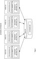
- FIG. 2 depicts a multi-node database system on which an embodiment may be implemented.
- system 200 comprises four nodes, 202, 212, 222, and 232. Although four nodes are shown in the present illustration, in other embodiments, system 200 may comprise fewer or more nodes.
- Each of nodes 202, 212, 222, and 232 have access to the same database 260.
- database 260 is shown as stored on a single shared disk 250, but in alternative embodiments may be spread across multiple disks to which each of nodes 202, 212, 222, and 232 have access.
- Nodes 202, 212, 222, and 232 respectively have one or more processors 208, 218, 228, and 238, and local volatile memory 204, 214, 224, and 234.
- nodes 202, 212, 222, and 232 are respectively executing database server instances 206, 216, 226, and 236. While in the illustrated embodiment each node is executing a single database server instance, in alternative embodiments, a single node may execute more than one database server instance.
- a database query may include a type of join operation known as a "multi-way join.”
- a multi-way join is a join operation that joins a plurality of tables.
- a query with a multi-way join may specify a plurality of tables to be joined together, and a plurality of join criteria for joining the plurality of tables.
- Each join criteria may include a pair of tables and join keys for merging the pair of tables.
- the join criteria may also include one or more join conditions.
- each join criteria in the multi-way join connects a table with the next table in the multi-way join.
- a database includes tables T1, T2, and T3.
- a multi-way join query that joins table T1, T2, and T3 may specify three join criteria: the first joining T1 and T2, the second joining T2 and T3, and the third joining T3 and T1.
- each join criteria has a table in common with the join criteria that appears before or after it in the query.
- the plurality of tables specified in a multi-way join do not need to all be distinct tables.
- the multi-way join may comprise one or more self-joins.
- a "self-join” merges rows of a table with other rows in the same table.
- a table T4 with employee information may include columns "employee_id" and "supervisor_id.”
- a self-join of table T4 may be used to determine which employees are supervisors of other employees.
- the self-join may specify that rows of T4 should be merged when the value of "employee id" for a row equals the value of "supervisor_id" of a second row in T4.
- instances of the same table may be referred to herein as different tables.
- aliases such as e1 and e2 are described herein as being two tables, when they may be instances of the same table.
- An "alias" is an alternate name used to refer to a table within a query.
- a multi-way join may be processed using a "multi-way hash join.”
- a multi-way hash join is a hash join that hashes all the tables in the multi-way join and then combines them to output the result, rather than combining only two tables in a single operation.
- the multi-way hash join partitions each table into join partitions, which may be stored in memory.
- Each database server instance 206, 216, 226, and 236 can receive a query and determine a query execution plan.
- the database server instance may receive a query and determine the query comprises multiple join criteria, each of which can be processed using hash joins.
- the database server instance may select a multi-way hash join, rather than a series of hash joins, to process the multiple join criteria.
- a multi-way hash join may be used to execute a query.
- the received query may comprise a plurality of tables connected by join criteria, wherein each join criteria connects a table with the next table in a multi-way join, as well as other join predicates or join criteria that do not connect a table with another table in the multi-way join.
- the database server instance may iteratively add each join criteria in the multi-way join to a list of join criteria to be processed with a multi-way hash join.
- each table in the plurality of tables may be partitioned into one or more groups, referred to as "join partitions.”
- the join partitions may be stored in the memory of a node, such as local memory 204, 214, 224, and 234, or on a disk, such as shared disk 250.
- join partitions are stored primarily in local volatile memory of a node. If the space allocated in memory is insufficient to hold data for a join partition, some or all of the join partition may be stored on disk. In an embodiment, if there is insufficient memory to store all of the data for a join partition, then the entire join partition is moved to disk.
- the number of partitions used for the multi-way hash join is based on cardinality of the multi-way join.
- the database system calculates an estimated cardinality for the multi-way join.
- the cardinality for a join indicates the number of rows in the result.
- the estimated cardinality for the multi-way join may be based on the cardinality for each join comprising the multi-way join.
- the number of partitions is equal to the cardinality of the multi-way join.
- rows of each table are assigned to one or more join partitions. If a row is assigned to a particular join partition, then the particular join partition may comprise a copy of the row. A row may be assigned to a partition based on the values in a corresponding column, referred to as a "partition key.”
- Rows in a table may be assigned to partitions using a hash function.
- the hash function is applied to the value in the partition key column for a row. Based on the result of the hash function, the row is assigned to a corresponding partition.
- the same hash function may be applied to the respective partition key for each table in the multi-way join.
- a row may be assigned to more than one partition based on how rows in other tables were assigned to partitions.
- join partitions are stored in local memory of a node. If a row is assigned to more than one partition, then it may be stored multiple times in memory, for each partition it is assigned to.
- the first two tables of the multi-way join are partitioned using a hash function.
- the remaining tables may be partitioned based on a partition map, as explained in further detail below.
- a partition map indicates, for a table, which one or more partitions each row of the table belongs to.
- the partition map for a table may be generated based on the partitions that the rows of the table have been assigned to. If rows of a table are assigned to partitions using a first column as the partition key, the partition map may be created based on the values in a second column and the partition assignments of the rows in the table.
- the second column used to generate the partition map may be a column that is specified as a join key for the table in a subsequent join criteria that includes the table. If a table has multiple columns that are used as join keys within a multi-way join, then a partition map may be generated for each column.
- An entry in a partition map indicates, for a value of the second column, the partition(s) the corresponding row(s) belong to based on the second column.
- a hash function is applied to the values in the second column to create the corresponding entry in the partition map.
- a table may be partitioned based on one or more partition maps previously created when partitioning other tables in the multi-way join. Assume a join criteria connects a first table and a second table on a join key, and the first table was partitioned based on a different join criteria and a different join key. A partition map was created for the first table based on the join key, corresponding to which partitions rows of the first table were assigned to. Rows of the second table may be partitioned with the join key as the partition key and using the partition map. The value in the partition key column for a row is used to look up a corresponding entry in the partition map. If the value is found in the partition map, the row is assigned to the partition(s) indicated in the corresponding entry of the partition map. If the value is not found in the partition map, then the row does not match with any row in the first table. That row may be discarded and not assigned to a partition.
- partitions Since rows are assigned to partitions based on join criteria and the way other tables were partitioned, a partition for a table contains rows of that table that could potentially be merged with rows of other tables assigned to the same partition. Merging tables based on partitions reduces the number of comparisons that would need to be made for rows of tables that are being joined.
- the first two tables specified in a multi-way join query are partitioned using a hash function.
- the remaining tables in the multi-way join query are partitioned based on partition maps.
- FIG. 3 is a block diagram illustrating the steps performed by a database system to perform a multi-way hash join, according to an embodiment.
- a database server instance receives a query comprising a multi-way join.
- the database server instance may parse the query to determine a portion of the query that comprises the multi-way join, and select an execution plan that uses a multi-way hash join.
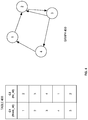
- database 260 comprises a table 400.
- Table 400 is referred to as an "edge” table.
- Edge table 400 represents the edges illustrated in directed graph 450, with columns for "from_id” (table400.C1) and “to id” (table400.C2).
- "From_id” indicates the starting point of an edge in directed graph 450 and "to_id” indicates the end point of the edge.
- database server instance 206 at node 202 in system 200 receives the following query for table 400 that includes a multi-way join:
- the query uses aliases to refer to each reference to table 400.
- aliases e1, e2, e3, and e4 are used to refer to table 400.
- the query comprises a multi-way join specifying four self-joins of table 400 with four join criteria:
- database server instance 206 partitions the first two tables involved in a join of the multi-way join using a hash function. For the purpose of illustrating a clear example, assume four partitions are used to partition the tables for the received query. Applying the hash function to a value of "1" results in assigning the row to partition p1, a value of "2" to partition p2, a value of "3” to partition p3, and a value of "4" to partition p4.
- FIG. 5 it illustrates partitions for table e1 and e2.
- the join key corresponding to each table is used as the partition key for partitioning the respective table.
- the join key for table e1 is the "to_id” column (e1.C2), so the "to_id” column is used as the partition key for partitioning table e1.
- the hash function is applied to the value in the "to_id” column of each row in table e1 to determine which partition the row is assigned to.
- Row (1,2) has a value of 2 in the "to id” column, so row (1,2) is assigned to partition p2.
- Row (2,3) has a value of 3 in the "to_id” column, so row (2,3) is assigned to partition p3.
- Row (3,4) has a value of 4 in the "to id” column, so row (3,4) is assigned to partition p4.
- Row (4,1) has a value of 1 in the "to id” column, so row (4,1) is assigned to partition p1.
- Row (3,2) has a value of 2 in the "to id” column, so row (3,2) is also assigned to partition p2.
- the partitions for table e1 contain the following rows:
- the hash function is also applied to table e2, using "from id” as the partition key to determine which partition each row of table e2 is assigned to.
- Row (1,2) has a value of 1 in the "from_id” column, so row (1,2) is assigned to partition p1.
- Row (2,3) has a value of 2 in the "from id” column, so row (2,3) is assigned to partition p2.
- Row (3,4) has a value of 3 in the "from_id” column, so row (3,4) is assigned to partition p3.
- Row (4,1) has a value of 4 in the "from_id” column, so row (4,1) is assigned to partition p4.
- Row (3,2) has a value of 3 in the "from id” column, so row (3,2) is assigned to partition p3.
- the partitions for table e2 contain the following rows:
- database server instance 106 generates partition maps based on the partitions for the first two tables.
- Partition map pm1 is a partition map for table e1 and partition map pm2 is a partition map for table e2.
- Table e1 was partitioned using the "to id" column as a partition key.
- Partition map pm1 indicates, for each value of "from_id,” the partitions that a corresponding row, containing that column value, was assigned to.
- the "from_id" value is 1 and row (1,2) was assigned to partition 2.
- row 602 in FIG. 6 the row in the partition map pm1 indicates that rows with "from id" value of 1 were assigned to partition p2.
- each partition is indicated in the partition map. For example, a "from_id" value of 3 corresponds to two rows: row (3,4) and row (3,2). Row (3,4) was assigned to partition p4 and row (3,2) was assigned to partition p2, so partition map pm1 indicates that rows with a "from_id" value of 3 were assigned to partitions p2 and p4.
- the database server instance 106 partitions one or more remaining tables based on one or more generated partition maps.
- FIG. 7 it illustrates the partition assignments and partition maps for table e3.
- Table 710 indicates the rows assigned to each partition, and partition map pm3 is generated for table e3 based on the partitions and values in the "to id" column.
- partition map pm2 was generated for table e2 based on the "to id" column (e2.C2) and indicates, for each value of "to id,” which partition corresponding rows were assigned to.
- Table e3 may be partitioned using "from id" (e3.C2) as the partition key and based on the mappings indicated by partition map pm2.
- row (1,2) of table e3 has a value of 1 in the "from _id" column.
- the value of 1 is used to look up a corresponding partition in partition map pm2. Referring to partition map pm2, a value of 1 in the "to_id" column is mapped to partition p4 so row (1,2) of table e3 is also assigned to partition p4.
- a row may be assigned to more than one partition.
- row (2,3) has a value of 2 in the "from_id" column. Referring to partition map pm2, it indicates that a value of 2 is assigned to both partition p1 and partition p3. Thus, row (2,3) is assigned to both partition p1 and partition p3.
- the partitions for table e3 contain the following rows:
- table 810 illustrates the partition assignments for table e4.
- Partition map pm1 was already created for table e1 and partition map pm3 was created for table e3.
- table e4 is partitioned based on both the "to_id” column (e4.C2), the "from_id” column (e4.C1), as well as both pm1 and pm3.
- partitions may be filtered based on two or more partition maps. If a row would be assigned to a particular partition based on a first partition map, but not assigned to that partition based on a second partition map, then the row is not assigned to the particular partition. That is, an AND operation may be used on a plurality of partition assignments derived from a plurality of partition maps in order to determine partition assignments.
- row (1,2) is assigned to partition p3.
- row (1,2) is also assigned to partition p3. Since the partition assignments are the same, row (1,2) for table e4 is assigned to partition p3.
- row (3,4) is assigned to partition p1.
- row (3,4) is assigned to partition p1 and p3. Since only partition p1 is in common, row (3,4) of table 4 is only assigned to partition p1.
- row may be filtered out and not assigned to a partition at all. For example, based on partition map pm1, row (3,2) is assigned to partition p2 and p4. Based on partition map pm3, row (3,2) is assigned to partition p1. Since there are no partitions in common, row (3,2) is not assigned to any partition and is not shown in table 810.
- the rows of the last table in the multi-way join are partitioned but not stored in memory with the other rows in the partitions. Instead, the rows are used directly to find and return the results for the multi-way join. In an embodiment, if the partition is stored on disk, then the rows assigned to that partition are still stored to disk.
- database server instance 206 determines results for the multi-way join based on the partitions for each table. If some or all of a partition is stored on disk, the partition is read from disk.
- first table is connected to a second table by a join criteria
- rows of the first table are compared with rows of the second table to determine whether the rows satisfy the join criteria.
- only rows that were assigned to the same partitions are compared.
- partition p1 contains:
- hash tables are used to find matching rows in the partitions.
- Hash tables may be created based on the join criteria in the multi-way join query, and then rows from each table are used to probe the hash table for the corresponding join criteria.
- Each hash table is created with the corresponding join key as the hash key.
- three hash tables may be created:
- a hash table is created for each partition of each table.
- a hash table for partition 1 on table e1 would contain only the rows from table e1 that were assigned to partition 1
- a hash table for partition 1 on table e2 would contain only the rows from table e2 that were assigned to partition 1, and so on.
- the rows from the last table are compared with the rows from the preceding table. Rows from the preceding table that satisfy the join criteria may then be used to check any preceding join criteria containing that table, iteratively, until all tables have been checked. For a particular row, if corresponding rows were found in all tables, then the rows may be merged and a result returned.
- Value 4 would be hashed for table e4 and value 1 would be hashed for table e2. Both return a result of row (4,1) of table e1. Since a row was found for all probes, a result was found and may be returned.
- a particular query may be received by a single node, but then the work of the query may be distributed to multiple nodes in a cluster. Each row of a table may be assigned and sent to a node for processing the query.
- a row may be assigned to a node using a hash function.
- a hash function may be applied to the values in a column of the row, such as a join key in a join criteria that includes the table. Based on the result of the hash function, the row is assigned to a corresponding node.
- the first two tables in the multi-join query are distributed to nodes in a cluster using a hash function.
- the remaining tables may be distributed based on a distribution map.
- a distribution map indicates, for a table, which node each row of the table was sent to. If rows of a table are distributed based to nodes based on a first column, then the distribution map may be created based on a second column and the node assignments, similar to the process described above for creating partition maps. An entry in the distribution map indicates, for a value of a particular column, the node that the corresponding row(s) were assigned to.
- database server instance 206 on node 202 receives the query comprising the multi-way join.
- database server instance 206 divides the work for the multi-way hash join by assigning rows of each table to one or more of nodes 202, 212, 222, and 232.
- the work may be further divided between the one or more processors 208, 218, 228, and 238.
- Rows of table e1 may be assigned to nodes based on the join key for the first join criteria.
- the hash function is applied to the value in the "to id" column of each row in table e1 to determine which node to send the row to.
- Row (1,2) has a value of 2 in the "to id” column, so row (1,2) is assigned to node 212.
- Row (2,3) has a value of 3 in the "to_id” column, so row (2,3) is assigned to node 222.
- Row (3,4) has a value of 4 in the "to id” column, so row (3,4) is assigned to node 232.
- Row (4,1) has a value of 1 in the "to_id” column, so row (4,1) is assigned to node 202.
- Row (3,2) has a value of 2 in the "to id” column, so row (3,2) is also assigned to node 212.
- a distribution map is generated based on the node assignments of the rows of table e1.
- the distribution map for table e1 would indicate that a "from_id" value of 1 is assigned to node 212, a value of 2 is assigned to node 222, a value of 3 is assigned to nodes 212 and 232, and a value of 4 is assigned to node 202.
- rows of table e4 may be sent to nodes 202, 212, 222, and 232 based on the distribution maps for table e1 and e3.
- Each node performs the multi-way hash join for its assigned rows as described above.
- the nodes may send the results back to the database server instance after they have finished processing the multi-way hash join.
- the techniques described herein are implemented by one or more special-purpose computing devices.
- the special-purpose computing devices may be hard-wired to perform the techniques, or may include digital electronic devices such as one or more application-specific integrated circuits (ASICs) or field programmable gate arrays (FPGAs) that are persistently programmed to perform the techniques, or may include one or more general purpose hardware processors programmed to perform the techniques pursuant to program instructions in firmware, memory, other storage, or a combination.
- ASICs application-specific integrated circuits
- FPGAs field programmable gate arrays
- Such special-purpose computing devices may also combine custom hard-wired logic, ASICs, or FPGAs with custom programming to accomplish the techniques.
- the special-purpose computing devices may be desktop computer systems, portable computer systems, handheld devices, networking devices or any other device that incorporates hard-wired and/or program logic to implement the techniques.
- FIG. 9 is a block diagram that illustrates a computer system 900 upon which an embodiment of the invention may be implemented.
- Computer system 900 includes a bus 902 or other communication mechanism for communicating information, and a hardware processor 904 coupled with bus 902 for processing information.
- Hardware processor 904 may be, for example, a general purpose microprocessor.
- Computer system 900 also includes a main memory 906, such as a random access memory (RAM) or other dynamic storage device, coupled to bus 902 for storing information and instructions to be executed by processor 904.
- Main memory 906 also may be used for storing temporary variables or other intermediate information during execution of instructions to be executed by processor 904.
- Such instructions when stored in non-transitory storage media accessible to processor 904, render computer system 900 into a special-purpose machine that is customized to perform the operations specified in the instructions.
- Computer system 900 further includes a read only memory (ROM) 908 or other static storage device coupled to bus 902 for storing static information and instructions for processor 904.
- ROM read only memory
- a storage device 910 such as a magnetic disk, optical disk, or solid-state drive is provided and coupled to bus 902 for storing information and instructions.
- Computer system 900 may be coupled via bus 902 to a display 912, such as a cathode ray tube (CRT), for displaying information to a computer user.
- a display 912 such as a cathode ray tube (CRT)
- An input device 914 is coupled to bus 902 for communicating information and command selections to processor 904.
- cursor control 916 is Another type of user input device
- cursor control 916 such as a mouse, a trackball, or cursor direction keys for communicating direction information and command selections to processor 904 and for controlling cursor movement on display 912.
- This input device typically has two degrees of freedom in two axes, a first axis (e.g., x) and a second axis (e.g., y), that allows the device to specify positions in a plane.
- Computer system 900 may implement the techniques described herein using customized hard-wired logic, one or more ASICs or FPGAs, firmware and/or program logic which in combination with the computer system causes or programs computer system 900 to be a special-purpose machine. According to one embodiment, the techniques herein are performed by computer system 900 in response to processor 904 executing one or more sequences of one or more instructions contained in main memory 906. Such instructions may be read into main memory 906 from another storage medium, such as storage device 910. Execution of the sequences of instructions contained in main memory 906 causes processor 904 to perform the process steps described herein. In alternative embodiments, hard-wired circuitry may be used in place of or in combination with software instructions.
- Non-volatile media includes, for example, optical disks, magnetic disks, or solid-state drives, such as storage device 910.
- Volatile media includes dynamic memory, such as main memory 906.
- storage media include, for example, a floppy disk, a flexible disk, hard disk, solid-state drive, magnetic tape, or any other magnetic data storage medium, a CD-ROM, any other optical data storage medium, any physical medium with patterns of holes, a RAM, a PROM, and EPROM, a FLASH-EPROM, NVRAM, any other memory chip or cartridge.
- Storage media is distinct from but may be used in conjunction with transmission media.
- Transmission media participates in transferring information between storage media.
- transmission media includes coaxial cables, copper wire and fiber optics, including the wires that comprise bus 902.
- transmission media can also take the form of acoustic or light waves, such as those generated during radio-wave and infra-red data communications.
- Various forms of media may be involved in carrying one or more sequences of one or more instructions to processor 904 for execution.
- the instructions may initially be carried on a magnetic disk or solid-state drive of a remote computer.
- the remote computer can load the instructions into its dynamic memory and send the instructions over a telephone line using a modem.
- a modem local to computer system 900 can receive the data on the telephone line and use an infra-red transmitter to convert the data to an infra-red signal.
- An infra-red detector can receive the data carried in the infra-red signal and appropriate circuitry can place the data on bus 902.
- Bus 902 carries the data to main memory 906, from which processor 904 retrieves and executes the instructions.
- the instructions received by main memory 906 may optionally be stored on storage device 910 either before or after execution by processor 904.
- Computer system 900 also includes a communication interface 918 coupled to bus 902.
- Communication interface 918 provides a two-way data communication coupling to a network link 920 that is connected to a local network 922.
- communication interface 918 may be an integrated services digital network (ISDN) card, cable modem, satellite modem, or a modem to provide a data communication connection to a corresponding type of telephone line.
- ISDN integrated services digital network
- communication interface 918 may be a local area network (LAN) card to provide a data communication connection to a compatible LAN.
- LAN local area network
- Wireless links may also be implemented.
- communication interface 918 sends and receives electrical, electromagnetic or optical signals that carry digital data streams representing various types of information.
- Network link 920 typically provides data communication through one or more networks to other data devices.
- network link 920 may provide a connection through local network 922 to a host computer 924 or to data equipment operated by an Internet Service Provider (ISP) 926.
- ISP 926 in turn provides data communication services through the world wide packet data communication network now commonly referred to as the "Internet" 928.
- Internet 928 uses electrical, electromagnetic or optical signals that carry digital data streams.
- the signals through the various networks and the signals on network link 920 and through communication interface 918, which carry the digital data to and from computer system 900, are example forms of transmission media.
- Computer system 900 can send messages and receive data, including program code, through the network(s), network link 920 and communication interface 918.
- a server 930 might transmit a requested code for an application program through Internet 928, ISP 926, local network 922 and communication interface 918.
- the received code may be executed by processor 904 as it is received, and/or stored in storage device 910, or other non-volatile storage for later execution.
Landscapes
- Engineering & Computer Science (AREA)
- Theoretical Computer Science (AREA)
- Data Mining & Analysis (AREA)
- Databases & Information Systems (AREA)
- Physics & Mathematics (AREA)
- General Engineering & Computer Science (AREA)
- General Physics & Mathematics (AREA)
- Computational Linguistics (AREA)
- Software Systems (AREA)
- Operations Research (AREA)
- Information Retrieval, Db Structures And Fs Structures Therefor (AREA)
- Data Exchanges In Wide-Area Networks (AREA)
Claims (11)
- Verfahren, das umfasst:Empfangen, bei einem Datenbanksystem (200), einer Abfrage, die eine Mehrweg-Verbundbildung mit einer Mehrzahl von Verbundbildungsoperationen umfasst, wobei jede Verbundbildungsoperation der Mehrzahl von Verbundbildungsoperationen mit einem jeweiligen ersten Verbundschlüssel einer jeweiligen ersten Tabelle und einem jeweiligen zweiten Verbundschlüssel einer jeweiligen zweiten Tabelle in Beziehung steht;wobei die Mehrzahl von Verbundbildungsoperationen eine erste Verbundbildungsoperation, eine zweite Verbundbildungsoperation und eine dritte Verbundbildungsoperation umfasst;für die erste Verbundbildungsoperation:Partitionieren der jeweiligen ersten Tabelle der ersten Verbundbildungsoperation in eine Mehrzahl von Partitionen, und zwar beruhend auf dem jeweiligen ersten Verbundschlüssel der ersten Verbundbildungsoperation;Erzeugen einer ersten Partitionszuordnung, die Werte, die in einem jeweiligen ersten Verbundschlüssel der zweiten Verbundbildungsoperation enthalten sind, der Mehrzahl von Partitionen zuordnet, wobei der jeweilige erste Verbundschlüssel der zweiten Verbundbildungsoperation eine Spalte der jeweiligen ersten Tabelle der ersten Verbundbildungsoperation ist;Partitionieren der jeweiligen zweiten Tabelle der ersten Verbundbildungsoperation in die Mehrzahl von Partitionen, und zwar beruhend auf dem jeweiligen zweiten Verbundschlüssel der ersten Verbundbildungsoperation;Erzeugen einer zweiten Partitionszuordnung, die Werte, die in einem jeweiligen ersten Verbundschlüssel der dritten Verbundbildungsoperation enthalten sind, der Mehrzahl von Partitionen zuordnet, wobei der jeweilige erste Verbundschlüssel der dritten Verbundbildungsoperation eine Spalte der jeweiligen zweiten Tabelle der ersten Verbundbildungsoperation ist;Partitionieren der jeweiligen zweiten Tabelle der zweiten Verbundbildungsoperation, und zwar beruhend auf der ersten Partitionszuordnung und dem jeweiligen zweiten Verbundschlüssel der zweiten Verbundbildungsoperation;Partitionieren der jeweiligen zweiten Tabelle der dritten Verbundbildungsoperation, und zwar beruhend auf der zweiten Partitionszuordnung und dem jeweiligen zweiten Verbundschlüssel der dritten Verbundbildungsoperation; undBestimmen, zumindest beruhend auf der Mehrzahl von Partitionen, von Ergebnissen für die Mehrweg-Verbundbildung, wobei, wenn zwei Tabellen durch ein Verbundkriterium verbunden sind, nur Zeilen, die denselben Partitionen zugeordnet wurden, verglichen werden, um zu bestimmen, ob die Zeilen das Verbundkriterium erfüllen.
- Verfahren nach Anspruch 1, wobei das Partitionieren der jeweiligen ersten Tabelle und der jeweiligen zweiten Tabelle der ersten Verbundbildungsoperation umfasst:Anwenden einer Hash-Funktion auf den jeweiligen ersten Verbundschlüssel; undAnwenden einer Hash-Funktion auf den jeweiligen zweiten Verbundschlüssel.
- Verfahren nach Anspruch 1, ferner umfassend:Erzeugen einer dritten Partitionszuordnung, die Werte, die in einem jeweiligen zweiten Verbundschlüssel der dritten Verbundbildungsoperation enthalten sind, zuordnet, wobei der jeweilige zweite Verbundschlüssel der dritten Verbundbildungsoperation eine Spalte der jeweiligen zweiten Tabelle der zweiten Verbundbildungsoperation ist;Partitionieren der jeweiligen zweiten Tabelle der dritten Verbundbildungsoperation, und zwar beruhend auf der zweiten Partitionszuordnung und der dritten Partitionszuordnung.
- Verfahren nach Anspruch 3, ferner umfassend:
Filtern einer oder mehrerer Zeilen der jeweiligen zweiten Tabelle der dritten Verbundbildungsoperation, und zwar beruhend auf der zweiten Partitionszuordnung und der dritten Partitionszuordnung. - Verfahren nach Anspruch 1, ferner umfassend, dass die Mehrzahl von Partitionen in einem lokalen Speicher (204, 214, 224, 234) des Datenbanksystems (200) gespeichert wird.
- Verfahren nach Anspruch 5, ferner umfassend, dass eine bestimmte Partition in einem Plattenspeicher (250) gespeichert wird, wenn der lokale Speicher (204, 214, 224, 234) des Datenbanksystems (200) nicht die gesamte Partition speichern kann.
- Verfahren nach Anspruch 1, wobei das Datenbanksystem (200) ein Mehrknoten-Datenbanksystem (200) ist, wobei das Verfahren ferner umfasst:Zuweisen von Zeilen der ersten jeweiligen Tabelle und der zweiten jeweiligen Tabelle der ersten Verbundbildungsoperation zu einem oder mehreren Knoten (202, 212, 222, 232) des Mehrknoten-Datenbanksystems (200);beruhend auf der Zuweisung erfolgendes Erzeugen eines Verteilungsplans;beruhend auf dem Verteilungsplan erfolgendes Zuweisen von Zeilen der ersten jeweiligen Tabelle und der zweiten jeweiligen Tabelle der zweiten Verbundbildungsoperation und der dritten Verbundbildungsoperation zu dem einen oder den mehreren Knoten (202, 212, 222, 232) in dem Mehrknoten-Datenbanksystem (200); undjeder des einen oder der mehreren Knoten (202, 212, 222, 232) führt das Partitionieren und Erzeugen für Tabellen durch, die dem Knoten (202, 212, 222, 232) zugewiesen sind.
- Verfahren nach Anspruch 7, ferner umfassend, dass die Mehrzahl von Partitionen in einem jeweiligen lokalen Speicher (204, 214, 224, 234) des einen oder der mehreren Knoten (202, 212, 222, 232) gespeichert werden.
- Verfahren nach Anspruch 8, ferner umfassend, dass eine bestimmte Partition in einem gemeinsam genutzten Plattenspeicher (250) gespeichert wird, wenn der jeweilige lokale Speicher (204, 214, 224, 234) nicht die gesamte Partition speichern kann.
- Verfahren nach Anspruch 1, wobei das Bestimmen von Ergebnissen für die Mehrweg-Verbundbildung ferner umfasst:Erzeugen einer ersten Hash-Tabelle, und zwar beruhend auf der jeweiligen zweiten Tabelle für die erste Verbundbildungsoperation und dem jeweiligen zweiten Verbundschlüssel der ersten Verbundbildungsoperation;Erzeugen einer zweiten Hash-Tabelle, und zwar beruhend auf der jeweiligen ersten Tabelle der zweiten Verbundbildungsoperation und dem jeweiligen ersten Verbundschlüssel der zweiten Verbundbildungsoperation;wobei das Bestimmen von Ergebnissen auf der ersten Hash-Tabelle und der zweiten Hash-Tabelle beruht.
- Ein oder mehrere nicht-transitorische computerlesbare Medien, die Instruktionen speichern, wobei die Instruktionen Instruktionen aufweisen, die, wenn sie von einem oder mehreren Hardware-Prozessoren (208, 218, 228, 238, 904) ausgeführt werden, bewirken, dass Operationen ausgeführt werden, die die in einem der Ansprüche 1-10 genannten Operationen umfassen.
Applications Claiming Priority (2)
| Application Number | Priority Date | Filing Date | Title |
|---|---|---|---|
| US15/266,751 US10733186B2 (en) | 2016-09-15 | 2016-09-15 | N-way hash join |
| PCT/US2017/042319 WO2018052519A1 (en) | 2016-09-15 | 2017-07-17 | N-way hash join |
Publications (2)
| Publication Number | Publication Date |
|---|---|
| EP3513306A1 EP3513306A1 (de) | 2019-07-24 |
| EP3513306B1 true EP3513306B1 (de) | 2020-11-04 |
Family
ID=59501540
Family Applications (1)
| Application Number | Title | Priority Date | Filing Date |
|---|---|---|---|
| EP17746247.0A Active EP3513306B1 (de) | 2016-09-15 | 2017-07-17 | N-way-hash-join |
Country Status (4)
| Country | Link |
|---|---|
| US (1) | US10733186B2 (de) |
| EP (1) | EP3513306B1 (de) |
| CN (1) | CN109716321B (de) |
| WO (1) | WO2018052519A1 (de) |
Families Citing this family (8)
| Publication number | Priority date | Publication date | Assignee | Title |
|---|---|---|---|---|
| US11500931B1 (en) * | 2018-06-01 | 2022-11-15 | Amazon Technologies, Inc. | Using a graph representation of join history to distribute database data |
| CN110008238B (zh) * | 2019-03-12 | 2021-04-27 | 北京东方国信科技股份有限公司 | Nlj改进表连接方法及基于该改进方法的数据查询方法 |
| EP3885929A4 (de) * | 2019-09-11 | 2022-02-09 | Huawei Technologies Co., Ltd. | Verfahren, vorrichtung und system zur datenneuverteilung |
| US11126401B2 (en) | 2019-09-18 | 2021-09-21 | Bank Of America Corporation | Pluggable sorting for distributed databases |
| US11016978B2 (en) | 2019-09-18 | 2021-05-25 | Bank Of America Corporation | Joiner for distributed databases |
| US12135702B2 (en) | 2020-09-10 | 2024-11-05 | International Business Machines Corporation | Comparison of database data |
| US12067019B2 (en) * | 2021-11-30 | 2024-08-20 | Snowflake Inc. | Dynamic data restriction in a database clean room |
| KR20250131424A (ko) * | 2024-02-27 | 2025-09-03 | 에스케이하이닉스 주식회사 | 분산 처리 시스템 및 그 동작 방법 |
Family Cites Families (9)
| Publication number | Priority date | Publication date | Assignee | Title |
|---|---|---|---|---|
| US7882100B2 (en) * | 2005-01-24 | 2011-02-01 | Sybase, Inc. | Database system with methodology for generating bushy nested loop join trees |
| US8086593B2 (en) * | 2007-03-01 | 2011-12-27 | Microsoft Corporation | Dynamic filters for relational query processing |
| US9740735B2 (en) * | 2007-11-07 | 2017-08-22 | Microsoft Technology Licensing, Llc | Programming language extensions in structured queries |
| US7925656B2 (en) * | 2008-03-07 | 2011-04-12 | International Business Machines Corporation | Node level hash join for evaluating a query |
| KR101296683B1 (ko) * | 2011-03-23 | 2013-08-14 | 연세대학교 산학협력단 | 데이터 스트림에서의 다중 조인 질의 처리를 위한 2 페이즈 수행 방법 |
| US9355146B2 (en) * | 2012-06-29 | 2016-05-31 | International Business Machines Corporation | Efficient partitioned joins in a database with column-major layout |
| US8996544B2 (en) * | 2012-09-28 | 2015-03-31 | Oracle International Corporation | Pruning disk blocks of a clustered table in a relational database management system |
| US10896178B2 (en) * | 2016-03-30 | 2021-01-19 | Microsoft Technology Licensing, Llc | High performance query processing and data analytics |
| CN109729115B (zh) * | 2017-10-30 | 2023-03-21 | 张瑜 | 实现分布式计算的方法、装置、代理服务器、终端设备 |
-
2016
- 2016-09-15 US US15/266,751 patent/US10733186B2/en active Active
-
2017
- 2017-07-17 CN CN201780056805.XA patent/CN109716321B/zh active Active
- 2017-07-17 EP EP17746247.0A patent/EP3513306B1/de active Active
- 2017-07-17 WO PCT/US2017/042319 patent/WO2018052519A1/en not_active Ceased
Non-Patent Citations (1)
| Title |
|---|
| None * |
Also Published As
| Publication number | Publication date |
|---|---|
| CN109716321A (zh) | 2019-05-03 |
| WO2018052519A1 (en) | 2018-03-22 |
| CN109716321B (zh) | 2023-07-28 |
| EP3513306A1 (de) | 2019-07-24 |
| US10733186B2 (en) | 2020-08-04 |
| US20180075101A1 (en) | 2018-03-15 |
Similar Documents
| Publication | Publication Date | Title |
|---|---|---|
| US10733186B2 (en) | N-way hash join | |
| CN111382174B (zh) | 多方数据联合查询方法、装置、服务器和存储介质 | |
| EP3058690B1 (de) | System und verfahren zur erzeugung eines verteilten transaktionsmanagers für wiederholbare leseisolierungsniveaus in einer mpp-datenbank | |
| JP6258549B2 (ja) | 個別のデータ値に対する効率よい演算を行うための方法、装置、並びにコンピュータ可読媒体 | |
| US6954776B1 (en) | Enabling intra-partition parallelism for partition-based operations | |
| US10769147B2 (en) | Batch data query method and apparatus | |
| US10885034B2 (en) | Data query method and apparatus, and database system | |
| US11249973B2 (en) | Querying partitioned tables in a distributed database | |
| CN108984639B (zh) | 服务器集群的数据处理方法和装置 | |
| CN110502519B (zh) | 一种数据聚合的方法、装置、设备及存储介质 | |
| EP4022459B1 (de) | Rewrite-technik für materialisierte ansichten von einseitigen outer-join queris | |
| US20150170316A1 (en) | Subgraph-based distributed graph processing | |
| US9104713B2 (en) | Managing a temporal key property in a database management system | |
| US20180314733A1 (en) | Dynamic operation scheduling for distributed data processing | |
| US20160179836A1 (en) | Method for updating data table of keyvalue database and apparatus for updating table data | |
| US10489386B2 (en) | Managing transactions requesting non-existing index keys in database systems | |
| US20120330988A1 (en) | Systems And Methods For Performing Index Joins Using Auto Generative Queries | |
| US20150261862A1 (en) | Search Space Reduction Using Approximate Results | |
| CN110851178B (zh) | 一种基于分布式图可达计算的过程间程序静态分析方法 | |
| US10313438B1 (en) | Partitioned key-value store with one-sided communications for secondary global key lookup by range-knowledgeable clients | |
| US9087085B2 (en) | Pre-assimilation values and post-assimilation values in hardware instance identifiers | |
| US9569507B2 (en) | Virtual directory server to process directory requests when information on an object is split across multiple data sources | |
| US11157500B2 (en) | Determination of query operator execution location | |
| EP4495795A1 (de) | Optimierung von index-join-abfragen | |
| US10353920B2 (en) | Efficient mirror data re-sync |
Legal Events
| Date | Code | Title | Description |
|---|---|---|---|
| STAA | Information on the status of an ep patent application or granted ep patent |
Free format text: STATUS: UNKNOWN |
|
| STAA | Information on the status of an ep patent application or granted ep patent |
Free format text: STATUS: THE INTERNATIONAL PUBLICATION HAS BEEN MADE |
|
| PUAI | Public reference made under article 153(3) epc to a published international application that has entered the european phase |
Free format text: ORIGINAL CODE: 0009012 |
|
| STAA | Information on the status of an ep patent application or granted ep patent |
Free format text: STATUS: REQUEST FOR EXAMINATION WAS MADE |
|
| 17P | Request for examination filed |
Effective date: 20190415 |
|
| AK | Designated contracting states |
Kind code of ref document: A1 Designated state(s): AL AT BE BG CH CY CZ DE DK EE ES FI FR GB GR HR HU IE IS IT LI LT LU LV MC MK MT NL NO PL PT RO RS SE SI SK SM TR |
|
| AX | Request for extension of the european patent |
Extension state: BA ME |
|
| RIN1 | Information on inventor provided before grant (corrected) |
Inventor name: SUBRAMANIAN, SANKAR Inventor name: BONDALAPATI, SRIKANTH Inventor name: WITKOWSKI, ANDREW Inventor name: AMOR, ANGELA |
|
| DAV | Request for validation of the european patent (deleted) | ||
| DAX | Request for extension of the european patent (deleted) | ||
| REG | Reference to a national code |
Ref country code: DE Ref legal event code: R079 Ref document number: 602017026877 Country of ref document: DE Free format text: PREVIOUS MAIN CLASS: G06F0017300000 Ipc: G06F0016245500 |
|
| GRAP | Despatch of communication of intention to grant a patent |
Free format text: ORIGINAL CODE: EPIDOSNIGR1 |
|
| STAA | Information on the status of an ep patent application or granted ep patent |
Free format text: STATUS: GRANT OF PATENT IS INTENDED |
|
| RIC1 | Information provided on ipc code assigned before grant |
Ipc: G06F 16/22 20190101ALI20200430BHEP Ipc: G06F 16/2455 20190101AFI20200430BHEP |
|
| INTG | Intention to grant announced |
Effective date: 20200518 |
|
| GRAS | Grant fee paid |
Free format text: ORIGINAL CODE: EPIDOSNIGR3 |
|
| GRAA | (expected) grant |
Free format text: ORIGINAL CODE: 0009210 |
|
| STAA | Information on the status of an ep patent application or granted ep patent |
Free format text: STATUS: THE PATENT HAS BEEN GRANTED |
|
| AK | Designated contracting states |
Kind code of ref document: B1 Designated state(s): AL AT BE BG CH CY CZ DE DK EE ES FI FR GB GR HR HU IE IS IT LI LT LU LV MC MK MT NL NO PL PT RO RS SE SI SK SM TR |
|
| REG | Reference to a national code |
Ref country code: GB Ref legal event code: FG4D |
|
| REG | Reference to a national code |
Ref country code: CH Ref legal event code: EP |
|
| REG | Reference to a national code |
Ref country code: AT Ref legal event code: REF Ref document number: 1331710 Country of ref document: AT Kind code of ref document: T Effective date: 20201115 |
|
| REG | Reference to a national code |
Ref country code: IE Ref legal event code: FG4D |
|
| REG | Reference to a national code |
Ref country code: DE Ref legal event code: R096 Ref document number: 602017026877 Country of ref document: DE |
|
| REG | Reference to a national code |
Ref country code: NL Ref legal event code: MP Effective date: 20201104 |
|
| REG | Reference to a national code |
Ref country code: AT Ref legal event code: MK05 Ref document number: 1331710 Country of ref document: AT Kind code of ref document: T Effective date: 20201104 |
|
| PG25 | Lapsed in a contracting state [announced via postgrant information from national office to epo] |
Ref country code: GR Free format text: LAPSE BECAUSE OF FAILURE TO SUBMIT A TRANSLATION OF THE DESCRIPTION OR TO PAY THE FEE WITHIN THE PRESCRIBED TIME-LIMIT Effective date: 20210205 Ref country code: FI Free format text: LAPSE BECAUSE OF FAILURE TO SUBMIT A TRANSLATION OF THE DESCRIPTION OR TO PAY THE FEE WITHIN THE PRESCRIBED TIME-LIMIT Effective date: 20201104 Ref country code: PT Free format text: LAPSE BECAUSE OF FAILURE TO SUBMIT A TRANSLATION OF THE DESCRIPTION OR TO PAY THE FEE WITHIN THE PRESCRIBED TIME-LIMIT Effective date: 20210304 Ref country code: RS Free format text: LAPSE BECAUSE OF FAILURE TO SUBMIT A TRANSLATION OF THE DESCRIPTION OR TO PAY THE FEE WITHIN THE PRESCRIBED TIME-LIMIT Effective date: 20201104 Ref country code: NO Free format text: LAPSE BECAUSE OF FAILURE TO SUBMIT A TRANSLATION OF THE DESCRIPTION OR TO PAY THE FEE WITHIN THE PRESCRIBED TIME-LIMIT Effective date: 20210204 |
|
| PG25 | Lapsed in a contracting state [announced via postgrant information from national office to epo] |
Ref country code: AT Free format text: LAPSE BECAUSE OF FAILURE TO SUBMIT A TRANSLATION OF THE DESCRIPTION OR TO PAY THE FEE WITHIN THE PRESCRIBED TIME-LIMIT Effective date: 20201104 Ref country code: ES Free format text: LAPSE BECAUSE OF FAILURE TO SUBMIT A TRANSLATION OF THE DESCRIPTION OR TO PAY THE FEE WITHIN THE PRESCRIBED TIME-LIMIT Effective date: 20201104 Ref country code: BG Free format text: LAPSE BECAUSE OF FAILURE TO SUBMIT A TRANSLATION OF THE DESCRIPTION OR TO PAY THE FEE WITHIN THE PRESCRIBED TIME-LIMIT Effective date: 20210204 Ref country code: SE Free format text: LAPSE BECAUSE OF FAILURE TO SUBMIT A TRANSLATION OF THE DESCRIPTION OR TO PAY THE FEE WITHIN THE PRESCRIBED TIME-LIMIT Effective date: 20201104 Ref country code: PL Free format text: LAPSE BECAUSE OF FAILURE TO SUBMIT A TRANSLATION OF THE DESCRIPTION OR TO PAY THE FEE WITHIN THE PRESCRIBED TIME-LIMIT Effective date: 20201104 Ref country code: LV Free format text: LAPSE BECAUSE OF FAILURE TO SUBMIT A TRANSLATION OF THE DESCRIPTION OR TO PAY THE FEE WITHIN THE PRESCRIBED TIME-LIMIT Effective date: 20201104 Ref country code: IS Free format text: LAPSE BECAUSE OF FAILURE TO SUBMIT A TRANSLATION OF THE DESCRIPTION OR TO PAY THE FEE WITHIN THE PRESCRIBED TIME-LIMIT Effective date: 20210304 |
|
| REG | Reference to a national code |
Ref country code: LT Ref legal event code: MG9D |
|
| PG25 | Lapsed in a contracting state [announced via postgrant information from national office to epo] |
Ref country code: HR Free format text: LAPSE BECAUSE OF FAILURE TO SUBMIT A TRANSLATION OF THE DESCRIPTION OR TO PAY THE FEE WITHIN THE PRESCRIBED TIME-LIMIT Effective date: 20201104 |
|
| PG25 | Lapsed in a contracting state [announced via postgrant information from national office to epo] |
Ref country code: SM Free format text: LAPSE BECAUSE OF FAILURE TO SUBMIT A TRANSLATION OF THE DESCRIPTION OR TO PAY THE FEE WITHIN THE PRESCRIBED TIME-LIMIT Effective date: 20201104 Ref country code: EE Free format text: LAPSE BECAUSE OF FAILURE TO SUBMIT A TRANSLATION OF THE DESCRIPTION OR TO PAY THE FEE WITHIN THE PRESCRIBED TIME-LIMIT Effective date: 20201104 Ref country code: CZ Free format text: LAPSE BECAUSE OF FAILURE TO SUBMIT A TRANSLATION OF THE DESCRIPTION OR TO PAY THE FEE WITHIN THE PRESCRIBED TIME-LIMIT Effective date: 20201104 Ref country code: LT Free format text: LAPSE BECAUSE OF FAILURE TO SUBMIT A TRANSLATION OF THE DESCRIPTION OR TO PAY THE FEE WITHIN THE PRESCRIBED TIME-LIMIT Effective date: 20201104 Ref country code: RO Free format text: LAPSE BECAUSE OF FAILURE TO SUBMIT A TRANSLATION OF THE DESCRIPTION OR TO PAY THE FEE WITHIN THE PRESCRIBED TIME-LIMIT Effective date: 20201104 Ref country code: SK Free format text: LAPSE BECAUSE OF FAILURE TO SUBMIT A TRANSLATION OF THE DESCRIPTION OR TO PAY THE FEE WITHIN THE PRESCRIBED TIME-LIMIT Effective date: 20201104 |
|
| REG | Reference to a national code |
Ref country code: DE Ref legal event code: R097 Ref document number: 602017026877 Country of ref document: DE |
|
| PG25 | Lapsed in a contracting state [announced via postgrant information from national office to epo] |
Ref country code: DK Free format text: LAPSE BECAUSE OF FAILURE TO SUBMIT A TRANSLATION OF THE DESCRIPTION OR TO PAY THE FEE WITHIN THE PRESCRIBED TIME-LIMIT Effective date: 20201104 |
|
| PLBE | No opposition filed within time limit |
Free format text: ORIGINAL CODE: 0009261 |
|
| STAA | Information on the status of an ep patent application or granted ep patent |
Free format text: STATUS: NO OPPOSITION FILED WITHIN TIME LIMIT |
|
| 26N | No opposition filed |
Effective date: 20210805 |
|
| PG25 | Lapsed in a contracting state [announced via postgrant information from national office to epo] |
Ref country code: NL Free format text: LAPSE BECAUSE OF FAILURE TO SUBMIT A TRANSLATION OF THE DESCRIPTION OR TO PAY THE FEE WITHIN THE PRESCRIBED TIME-LIMIT Effective date: 20201104 Ref country code: AL Free format text: LAPSE BECAUSE OF FAILURE TO SUBMIT A TRANSLATION OF THE DESCRIPTION OR TO PAY THE FEE WITHIN THE PRESCRIBED TIME-LIMIT Effective date: 20201104 Ref country code: IT Free format text: LAPSE BECAUSE OF FAILURE TO SUBMIT A TRANSLATION OF THE DESCRIPTION OR TO PAY THE FEE WITHIN THE PRESCRIBED TIME-LIMIT Effective date: 20201104 |
|
| PG25 | Lapsed in a contracting state [announced via postgrant information from national office to epo] |
Ref country code: SI Free format text: LAPSE BECAUSE OF FAILURE TO SUBMIT A TRANSLATION OF THE DESCRIPTION OR TO PAY THE FEE WITHIN THE PRESCRIBED TIME-LIMIT Effective date: 20201104 |
|
| REG | Reference to a national code |
Ref country code: CH Ref legal event code: PL |
|
| PG25 | Lapsed in a contracting state [announced via postgrant information from national office to epo] |
Ref country code: MC Free format text: LAPSE BECAUSE OF FAILURE TO SUBMIT A TRANSLATION OF THE DESCRIPTION OR TO PAY THE FEE WITHIN THE PRESCRIBED TIME-LIMIT Effective date: 20201104 |
|
| REG | Reference to a national code |
Ref country code: BE Ref legal event code: MM Effective date: 20210731 |
|
| PG25 | Lapsed in a contracting state [announced via postgrant information from national office to epo] |
Ref country code: LI Free format text: LAPSE BECAUSE OF NON-PAYMENT OF DUE FEES Effective date: 20210731 Ref country code: CH Free format text: LAPSE BECAUSE OF NON-PAYMENT OF DUE FEES Effective date: 20210731 |
|
| PG25 | Lapsed in a contracting state [announced via postgrant information from national office to epo] |
Ref country code: IS Free format text: LAPSE BECAUSE OF FAILURE TO SUBMIT A TRANSLATION OF THE DESCRIPTION OR TO PAY THE FEE WITHIN THE PRESCRIBED TIME-LIMIT Effective date: 20210304 Ref country code: LU Free format text: LAPSE BECAUSE OF NON-PAYMENT OF DUE FEES Effective date: 20210717 Ref country code: FR Free format text: LAPSE BECAUSE OF NON-PAYMENT OF DUE FEES Effective date: 20210731 |
|
| PG25 | Lapsed in a contracting state [announced via postgrant information from national office to epo] |
Ref country code: IE Free format text: LAPSE BECAUSE OF NON-PAYMENT OF DUE FEES Effective date: 20210717 Ref country code: BE Free format text: LAPSE BECAUSE OF NON-PAYMENT OF DUE FEES Effective date: 20210731 |
|
| P01 | Opt-out of the competence of the unified patent court (upc) registered |
Effective date: 20230416 |
|
| PG25 | Lapsed in a contracting state [announced via postgrant information from national office to epo] |
Ref country code: CY Free format text: LAPSE BECAUSE OF FAILURE TO SUBMIT A TRANSLATION OF THE DESCRIPTION OR TO PAY THE FEE WITHIN THE PRESCRIBED TIME-LIMIT Effective date: 20201104 |
|
| PG25 | Lapsed in a contracting state [announced via postgrant information from national office to epo] |
Ref country code: HU Free format text: LAPSE BECAUSE OF FAILURE TO SUBMIT A TRANSLATION OF THE DESCRIPTION OR TO PAY THE FEE WITHIN THE PRESCRIBED TIME-LIMIT; INVALID AB INITIO Effective date: 20170717 |
|
| PG25 | Lapsed in a contracting state [announced via postgrant information from national office to epo] |
Ref country code: MK Free format text: LAPSE BECAUSE OF FAILURE TO SUBMIT A TRANSLATION OF THE DESCRIPTION OR TO PAY THE FEE WITHIN THE PRESCRIBED TIME-LIMIT Effective date: 20201104 |
|
| PG25 | Lapsed in a contracting state [announced via postgrant information from national office to epo] |
Ref country code: TR Free format text: LAPSE BECAUSE OF FAILURE TO SUBMIT A TRANSLATION OF THE DESCRIPTION OR TO PAY THE FEE WITHIN THE PRESCRIBED TIME-LIMIT Effective date: 20201104 |
|
| PG25 | Lapsed in a contracting state [announced via postgrant information from national office to epo] |
Ref country code: MT Free format text: LAPSE BECAUSE OF FAILURE TO SUBMIT A TRANSLATION OF THE DESCRIPTION OR TO PAY THE FEE WITHIN THE PRESCRIBED TIME-LIMIT Effective date: 20201104 |
|
| PGFP | Annual fee paid to national office [announced via postgrant information from national office to epo] |
Ref country code: GB Payment date: 20250529 Year of fee payment: 9 |
|
| PGFP | Annual fee paid to national office [announced via postgrant information from national office to epo] |
Ref country code: DE Payment date: 20250604 Year of fee payment: 9 |