EP3513264B1 - Lichtmessung mit verwwendung eines autonomen fahrzeugs - Google Patents
Lichtmessung mit verwwendung eines autonomen fahrzeugs Download PDFInfo
- Publication number
- EP3513264B1 EP3513264B1 EP17784070.9A EP17784070A EP3513264B1 EP 3513264 B1 EP3513264 B1 EP 3513264B1 EP 17784070 A EP17784070 A EP 17784070A EP 3513264 B1 EP3513264 B1 EP 3513264B1
- Authority
- EP
- European Patent Office
- Prior art keywords
- light
- measurement
- autonomous vehicle
- measuring
- plan
- Prior art date
- Legal status (The legal status is an assumption and is not a legal conclusion. Google has not performed a legal analysis and makes no representation as to the accuracy of the status listed.)
- Active
Links
Images




Classifications
-
- G—PHYSICS
- G01—MEASURING; TESTING
- G01J—MEASUREMENT OF INTENSITY, VELOCITY, SPECTRAL CONTENT, POLARISATION, PHASE OR PULSE CHARACTERISTICS OF INFRARED, VISIBLE OR ULTRAVIOLET LIGHT; COLORIMETRY; RADIATION PYROMETRY
- G01J1/00—Photometry, e.g. photographic exposure meter
- G01J1/02—Details
- G01J1/0266—Field-of-view determination; Aiming or pointing of a photometer; Adjusting alignment; Encoding angular position; Size of the measurement area; Position tracking; Photodetection involving different fields of view for a single detector
-
- G—PHYSICS
- G01—MEASURING; TESTING
- G01J—MEASUREMENT OF INTENSITY, VELOCITY, SPECTRAL CONTENT, POLARISATION, PHASE OR PULSE CHARACTERISTICS OF INFRARED, VISIBLE OR ULTRAVIOLET LIGHT; COLORIMETRY; RADIATION PYROMETRY
- G01J1/00—Photometry, e.g. photographic exposure meter
- G01J1/42—Photometry, e.g. photographic exposure meter using electric radiation detectors
- G01J1/4204—Photometry, e.g. photographic exposure meter using electric radiation detectors with determination of ambient light
-
- G—PHYSICS
- G05—CONTROLLING; REGULATING
- G05D—SYSTEMS FOR CONTROLLING OR REGULATING NON-ELECTRIC VARIABLES
- G05D1/00—Control of position, course, altitude or attitude of land, water, air or space vehicles, e.g. using automatic pilots
- G05D1/0094—Control of position, course, altitude or attitude of land, water, air or space vehicles, e.g. using automatic pilots involving pointing a payload, e.g. camera, weapon, sensor, towards a fixed or moving target
-
- B—PERFORMING OPERATIONS; TRANSPORTING
- B64—AIRCRAFT; AVIATION; COSMONAUTICS
- B64U—UNMANNED AERIAL VEHICLES [UAV]; EQUIPMENT THEREFOR
- B64U2101/00—UAVs specially adapted for particular uses or applications
-
- B—PERFORMING OPERATIONS; TRANSPORTING
- B64—AIRCRAFT; AVIATION; COSMONAUTICS
- B64U—UNMANNED AERIAL VEHICLES [UAV]; EQUIPMENT THEREFOR
- B64U2101/00—UAVs specially adapted for particular uses or applications
- B64U2101/05—UAVs specially adapted for particular uses or applications for sports or gaming, e.g. drone racing
-
- G—PHYSICS
- G01—MEASURING; TESTING
- G01J—MEASUREMENT OF INTENSITY, VELOCITY, SPECTRAL CONTENT, POLARISATION, PHASE OR PULSE CHARACTERISTICS OF INFRARED, VISIBLE OR ULTRAVIOLET LIGHT; COLORIMETRY; RADIATION PYROMETRY
- G01J1/00—Photometry, e.g. photographic exposure meter
- G01J1/02—Details
- G01J2001/0257—Details portable
-
- G—PHYSICS
- G08—SIGNALLING
- G08G—TRAFFIC CONTROL SYSTEMS
- G08G5/00—Traffic control systems for aircraft
- G08G5/30—Flight plan management
- G08G5/32—Flight plan management for flight plan preparation
-
- G—PHYSICS
- G08—SIGNALLING
- G08G—TRAFFIC CONTROL SYSTEMS
- G08G5/00—Traffic control systems for aircraft
- G08G5/50—Navigation or guidance aids
- G08G5/55—Navigation or guidance aids for a single aircraft
-
- G—PHYSICS
- G08—SIGNALLING
- G08G—TRAFFIC CONTROL SYSTEMS
- G08G5/00—Traffic control systems for aircraft
- G08G5/50—Navigation or guidance aids
- G08G5/57—Navigation or guidance aids for unmanned aircraft
Definitions
- the present invention relates to lighting, and more specifically, to light measurement using an autonomous vehicle.
- Measuring light levels in a stadium can be critical for several reasons. In the case of a televised sporting event, the ground needs to be properly lit for player visibility, viewing by the attending audience and television cameras. Light level measurements can indicate whether the playing surface is sufficiently illuminated and the light is distributed as required (that is, for uniform distribution, there are no aberrational bright or dark spots). These measurements can also be used to differentiate between issues with the lighting system and ground. For example, what may visually appear from the grandstand as a bright spot on the ground, may in fact be a patch of dry grass or the result of improper mowing.
- the measurement process is especially pertinent during the lighting system setup/commissioning phase to verify lighting design and positioning. It is also applicable when the lighting system is changed/upgraded and for routine servicing, testing and verification. Lighting requirements may also need to be verified before approval for certain events.
- NAA National Collegiate Athletic Association
- FIFA Federation Internationale de Football Association
- Light level measurements are typically performed manually.
- a portable light meter typically measuring in units of foot-candle or lux, is positioned on, or close to, the ground and pointed up towards the sky, lighting system and/or cameras to measure incident light. Measurements are typically performed at multiple positions to ascertain light distribution in addition to the intensity of illumination at any given point.
- US 2015/173147 A1 discloses a lighting system that includes a group of light emitting diode (LED) illumination devices, each of which includes a device driver.
- LED light emitting diode
- One or more sensors are configured to measure a characteristic of light received from the devices in an area of an environment that is illuminated by the devices.
- the sensor may be placed on or in a manually operated vehicle or drone.
- the vehicle or drone may be programmed with location and route data to automatically move to collect data.
- US 2015/035437 A1 discloses a lighting system having a movement system, a light source repositionable via the movement system, a sensor, a controller, and a communication system.
- the light source, the movement system, the controller, the sensor, and the communication system are installable in a drone.
- WO 2013/177059 A1 discloses that a subject is imaged using imaging equipment arranged on portable, wireless vehicles.
- the vehicles are positioned in a pattern in proximity to the subject and illuminate the subject in order to collect image data.
- the image data can be collected by cameras carried by the vehicles in addition to or instead of external high speed cameras.
- US 2016/227634 A1 discloses a method of taking light-measurement according to the preamble of claim 1.
- Embodiments are directed to systems, methods, and software for using one or more fully or semi-autonomous vehicles (for simplicity, "autonomous vehicle(s)”) to make measurements of lighting conditions in targeted space, such as a stadium, an arena, a sports field, a parking lot, an amusement park, a swimming pool, and an aquarium tank, among many other types of spaces.
- autonomous vehicle(s) for simplicity, “autonomous vehicle(s)”
- targeted space such as a stadium, an arena, a sports field, a parking lot, an amusement park, a swimming pool, and an aquarium tank, among many other types of spaces.
- targeted space such as a stadium, an arena, a sports field, a parking lot, an amusement park, a swimming pool, and an aquarium tank, among many other types of spaces.
- targeted space such as a stadium, an arena, a sports field, a parking lot, an amusement park, a swimming pool, and an aquarium tank, among many other types of spaces.
- Uses of such systems, software, and/or methods include, but are not limited to, verifying that required light intensity, distribution, camera image quality, and/or other performance metric(s) is/are met when commissioning, changing, checking, and approving lighting or other systems, among other things.
- Examples of autonomous vehicles that can be used in conjunction with light-measurement systems and methods disclosed herein include, but are not limited to, unmanned aerial vehicles (such as drones), terrestrial robots and unmanned terrestrial vehicles, and unmanned underwater vehicles, among others.
- Benefits of making light measurements may include, but are not limited to, collecting light-measurement data quicker than conventional methods and reducing the number of people needed to execute a light-measurement plan, thereby making the process more efficient.
- a method of taking light-measurement readings within a targeted space includes: receiving, for deployment of an autonomous vehicle having a light-measuring sensor, a light-measuring plan that includes an identification of a plurality of measurement positions for the autonomous vehicle in the targeted space; causing the autonomous vehicle to automatically move to each of the measurement positions based on the light-measuring plan; causing the light-measuring sensor to capture the light measurement at each of the measurement positions while the autonomous vehicle is at the corresponding one of the measurement positions based on the light-measuring plan; and storing, for each measurement position, the light measurement taken at that position and information identifying that position.
- the targeted space may have a lighting specification that includes the plurality of measurement locations and a corresponding target light-measurement value at each of the measurement locations.
- the method may further include automatically comparing each light measurement taken to the corresponding target light-measurement value.
- the targeted space may be a playing field, and the lighting specification may be a FIFA lighting specification.
- the autonomous vehicle may include an aerial vehicle and the light-measuring plan may include a flight path for the aerial vehicle that traverses a path that includes the plurality of measurement positions.
- the autonomous vehicle may include a terrestrial vehicle and the light-measuring plan may include a terrestrial route that traverses a path that includes the plurality of measurement positions.
- the autonomous vehicle may include a watercraft and the light-measuring plan may include a water-based route that traverses a path that includes the plurality of measurement positions.
- the method may further include moving the autonomous vehicle to each of the measurement positions using realtime positioning information. In still yet another related embodiment, the method may further include moving the autonomous vehicle to each of the measurement positions based on a local positioning reference.
- the method further includes controlling at least one of the autonomous vehicle and a movable mount to achieve an aim for light-measuring sensor.
- the light-measuring plan may include a path traversing the measurement positions, and the method further includes determining the path based on a deployment of the autonomous vehicle prior to executing the light-measuring plan.
- a non-transitory machine-readable storage medium containing machine-executable instructions configured to cause a processor of a light-measurement system to perform operations including: receiving, for deployment of an autonomous vehicle having a light-measuring sensor, a light-measuring plan that includes an identification of a plurality of measurement positions for the autonomous vehicle; causing the autonomous vehicle to automatically move to each of the measurement positions; causing the light-measuring sensor to automatically capture the light measurement at each of the measurement positions while the autonomous vehicle is the corresponding one of the measurement positions; and storing, for each measurement location, the light measurement taken at that position and information identifying that position.
- the targeted space may have a lighting specification that includes the plurality of measurement locations and a corresponding target light-measurement value at each of the measurement locations.
- the operations may further include automatically comparing each light measurement taken to the corresponding target light-measurement value.
- the targeted space may be a playing field, and the lighting specification may be a FIFA lighting specification.
- the autonomous vehicle may include an aerial vehicle and the light-measuring plan may include a flight path for the aerial vehicle that traverses a path that includes the plurality of measurement positions.
- the autonomous vehicle may include a terrestrial vehicle and the light-measuring plan may include a terrestrial route that traverses a path that includes the plurality of measurement positions.
- the autonomous vehicle may include a watercraft and the light-measuring plan may include a water-based route that traverses a path that includes the plurality of measurement positions.
- the operations may further include causing the autonomous vehicle to move to each of the measurement positions using realtime positioning information. In yet still another related embodiment, the operations may further include causing the autonomous vehicle to move to each of the measurement positions based on a local positioning reference.
- the operations may further include controlling at least one of the autonomous vehicle and a movable mount to achieve an aim for light-measuring sensor.
- the light-measuring plan includes a path traversing the measurement positions and the operations further include determining the path based on a deployment of the autonomous vehicle prior to executing the light-measuring plan.
- a light-measuring system to take light measurements within a targeted space.
- the system includes: an autonomous vehicle that includes locomotion system capable of moving the autonomous vehicle so that it traverses a path that includes measurement positions within the targeted space; a light-measuring sensor deployed on the autonomous vehicle to acquire the light measurement at each of the measurement positions; and a measurement-plan system configured to implement a measurement plan for acquiring the light measurements at the measurement positions, the measurement-plan system including: navigation instructions configured to cause the locomotion means to move the autonomous vehicle so that it traverses the path; and sensor instructions configured to cause the light-measuring sensor to capture the light measurement at each of the measurement positions.
- the autonomous vehicle may include an aerial vehicle, and the locomotion system may include hovering capability.
- the autonomous vehicle may include a terrestrial vehicle.
- the autonomous vehicle may include a watercraft.
- the autonomous vehicle may further include a global positioning system receiver, and the navigation instructions may cause the locomotion system to move the autonomous vehicle so that it traverses the path based on global positioning system information acquired by the global positioning system receiver.
- the autonomous vehicle may further include a positioning system that permits the autonomous vehicle to identify each measurement position based on a local positioning reference.
- the light-measuring sensor may be movably mounted to the autonomous vehicle, and the sensor instructions may include instructions to move the light-measuring sensor relative to the autonomous vehicle.
- FIG. 1 illustrates an example light-measuring method 100 in accordance with aspects of the present disclosure.
- light-measuring method 100 provides a method of making light measurements at a plurality of locations within a targeted space, which, as noted above, can be any indoor or outdoor space in which it is desired to collect light-measurement data.
- the nature of the light measurements is not limited in any manner and may be any type of light measurement, such as a photometric measurement, a radiometric measurement, or a spectrographic measurement, among others.
- more than one type of light measurement can be taken at each of the plurality of locations and that the type of reading(s) can vary among the plurality of locations within any given targeted space.
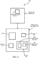
- Method 100 may be implemented using any suitable autonomous-vehicle-based light-measurement system, such as autonomous-vehicle-based light-measurement system 200 of FIG. 2 .
- method 100 is described in the context of autonomous-vehicle-based light-measurement system 200. Consequently, references will be made to FIG. 2 as well as FIG. 1 .
- FIG. 1 all 100-series numerals in the following description refer to FIG. 1
- all 200-series numerals refer to FIG. 2 .
- the references to autonomous-vehicle-based light-measurement system 200 relative to method 100 is merely for convenience and is not intended to limit the scope of the method.
- a light-measurement plan 204 for an autonomous-vehicle-based light-measurement system here, autonomous-vehicle-based light-measurement system 200 is received.
- autonomous-vehicle-based light-measurement system 200 includes an autonomous vehicle 208, a light-measuring sensor 212 mounted to the autonomous vehicle, and a measurement-plan system 216 that is in communication with the autonomous vehicle and, either directly or indirectly, with the light-measuring sensor.
- autonomous vehicle 208 may be any suitable fully or semi-autonomous vehicle, depending on the targeted space in which the autonomous vehicle will collect light-measurement data 220.
- light-measuring sensor 212 may be any suitable light-measuring sensor, such as a light sensor suitable for any one or more desired photometric, radiometric and spectrographic measurements, among others.
- the singular "light-measuring sensor” is intended to encompass a plurality of light-measuring sensors of the same or differing type.
- Light-measuring sensor 212 may be fixedly or movably mounted to autonomous vehicle 208 in any suitable manner.
- mounts may include rotational mounts, gimbaled mounts, and robotic arm mounts, among others.
- Measurement-plan system 216 may include any collection of software and hardware that provides the requisite functionality. As those skilled in the art will readily appreciate, measurement-plan system 216 may be embodied in any of a wide variety of forms; consequently, the hardware and software required will vary greatly among at least some of these forms. It is noted that while FIG. 2 illustrates measurement-plan system 216 as being separate and distinct from autonomous vehicle 208, this is in terms of functionality and not physical construct. Indeed, and as described below, one or more portions, or even the entirety, of measurement-plan system 216 may be physically integrated into autonomous vehicle 208. Following are some example forms that measurement-plan system 216 can take. However, these examples are not exhaustive and are not intended to cover every possibility. That said, those skilled in the art will be able to derive other embodiments using these examples and other information contained in this disclosure without undue experimentation.
- the form that measurement-plan system 216 takes can depend on the on-board computing power of autonomous vehicle 208 and the robustness of its user interface 228. For example, if autonomous vehicle 208 contains the entirety of software 224 and has a robust user interface 228 that allows a user to directly input light-measurement plan 204 directly into the autonomous vehicle, then the entire light-measurement-plan system 216 may reside on the autonomous vehicle primarily in the form of one or more computer processors 232, the user interface, and the corresponding software. However, if autonomous vehicle 208 is configured, for example, to only have enough onboard computing power to receive and execute a vehicle-specific instruction set received from an external device, then light-measurement-plan system 216 will have more of software 224 and hardware external to the autonomous vehicle.
- user interface 228 and portions of software 224 responsible for receiving light-measurement-plan 204, compiling the light-measurement plan into vehicle-specific instructions, and providing the vehicle-specific instructions to autonomous vehicle 208 may reside on a suitable external device (not shown), such as a laptop computer, desktop computer, smartphone, and application-specific device, among others.
- a suitable external device such as a laptop computer, desktop computer, smartphone, and application-specific device, among others.
- Light-measurement plan 204 includes an identification of a plurality of vehicle positions for autonomous vehicle 208 to traverse so as to allow the autonomous vehicle to take light measurements at a plurality of light-measurement locations.
- the light-measurement locations may be user-selected locations or locations prescribed by a light-measurement standard, or a combination thereof.
- the light-measurement locations may have a dimensionality of one (linear), two (planar), or three (volume) dimension(s). For example, for a 3-D dimensionality and using Cartesian space, each light-measurement location will have x, y, and z coordinates.
- Each light-measurement location may also have one or more light-sensor directionalities associated therewith.
- the light-measurement plan 204 will include information for autonomous vehicle 208 and/or other mechanism to properly aim the light-measurement sensor while at a particular measurement location.
- each corresponding light-measurement position of the autonomous vehicle will have, for example, either x, y, and z coordinates or x and y coordinates (such as on a horizontal grid), with the z-coordinate (vertical) of the light-measurement location being satisfied by a height of the autonomous vehicle and/or height of light-measuring sensor 212.
- Light-measurement plan 204 may also include other information, such as one or more paths for autonomous vehicle 208 to traverse to hit all of the light-measurement locations, directionality of light-measuring sensor 212 for acquiring a light measurement, an offset distance and/or direction of the light-measurement sensor from the origin of the axes assigned to autonomous vehicle 208, information for instructing the light-measuring sensor to take light measurements, and, if the light-measuring sensor is movably mounted to autonomous vehicle 208, information for controlling motion of the light-measuring sensor relative to the autonomous vehicle.
- other information such as one or more paths for autonomous vehicle 208 to traverse to hit all of the light-measurement locations, directionality of light-measuring sensor 212 for acquiring a light measurement, an offset distance and/or direction of the light-measurement sensor from the origin of the axes assigned to autonomous vehicle 208, information for instructing the light-measuring sensor to take light measurements, and, if the light-measuring sensor is
- autonomous vehicle 208 is caused to move to each of the light-measurement positions, for example, by traversing one or more planned movement paths for the autonomous vehicle.
- a movement path may be programmed directly into autonomous vehicle 208 as part of the light-measurement plan if the autonomous vehicle is provided with such functionality or it may be downloaded into the autonomous vehicle from an external device as an instruction set, and the autonomous vehicle may then be triggered to execute the instruction set using any suitable input(s), such as global positioning information or local positioning information, among other things.
- movement of autonomous vehicle 208 may be effected by realtime communication between the autonomous vehicle and a remove vehicle controller (not shown, but see FIG.
- an offboard movement controller may use one or more video cameras or other sensors to observe the movement of autonomous vehicle 208 and control movements of the autonomous vehicle using information from such observations and knowledge of the light-measurement locations.
- a user may operate a controller that displays, in realtime, the location of autonomous vehicle 208 and the locations of the light-measurement locations to the user and then allows the user to remotely control movements of the autonomous vehicle based on that visual input.
- Other manners of performing step 110 are possible.
- step 115 light-measurement sensor 212 is caused to capture the light measurements when autonomous vehicle 208 is at the measurement positions.
- step 115 can be performed in any suitable manner.
- step 115 can be accomplished automatically via a suitable control instruction set that causes autonomous vehicle 208 to make a measurement each time the autonomous vehicle is located at or proximate to, within a preset tolerance, a corresponding measurement position.
- step 115 may be effected by the user actuating a control on the remote controller that causes the light-measuring sensor to take a light measurement.
- Such a control can be either a soft control presented on a video display or a hard control, such as a physical button or other control.
- a soft control presented on a video display
- a hard control such as a physical button or other control.
- each light-measurement is stored in a memory 236 associated with autonomous-vehicle-based light-measurement system 200.
- Memory 236 may be located at any suitable location, such as onboard autonomous vehicle 208 or offboard the autonomous vehicle, such as at a remote controller or other device (laptop computer, desktop computer, smartphone, etc.) that is a local component of autonomous-vehicle-based light-measurement system 200 or on a server remote from the local components of the autonomous-vehicle-based light-measurement system 200. Fundamentally, there is no constraint on where memory 236 is located. Typically, information concerning the light-measurement locations will be stored in memory 236 in association with the light measurements.
- Such information may include coordinates (e.g., Cartesian coordinates) of each light-measurement location, a location identifier (e.g., a numeral, an alphanumeric code, a name, etc.), or a combination thereof, among others.
- coordinates e.g., Cartesian coordinates
- location identifier e.g., a numeral, an alphanumeric code, a name, etc.
- this example method 100 is implemented in the context of a playing surface 300A of a soccer stadium 300 using an aerial drone 304 that carries a lux meter 308.
- An exemplar of a systematic approach for light measurement of an area is outlined in the FIFA lighting specifications mentioned in the Background section above.
- a grid 400 having a 10m x 10m cell resolution across playing surface 300A is used as a basis for collecting the light measurements.
- this typically equates to either 77 (7 x 11) or 88 (8 x 11) grid vertices or measurement positions 404 (only a few labeled to avoid clutter).
- a tripod (not shown) is placed at each of these positions with a light sensor mounted (not shown) level to playing surface 300A.
- a series of measurements are then performed, including: a horizontal measurement at 1 meter above the surface with lux sensor 308 ( FIG. 3 ) pointing upwards perpendicular to playing surface 300A and a vertical measurement at 1.5 meters above the playing surface towards each fixed and field camera point (only one fixed camera 312 shown in FIG. 3 ).
- the measured values are then compared to the horizontal and vertical illuminance and uniformity specifications for compliance.
- lux sensor 308 is mounted to aerial drone 304 so that the lux sensor is able to be angled in an unobscured manner towards the sky 316 in a direction perpendicular to playing surface 300A and toward fixed and field cameras (only one fixed camera 316 illustrated around stadium 300.
- aerial drone 304 By following an autonomous and systematic flight path 408 ( FIG. 4 ) that traverses measurement positions 404 illustrated in FIG. 4 , aerial drone 304 ( FIG. 3 ) is able to rapidly perform a light measurement survey without contacting or interfering with playing surface 300A.
- Aerial drone 304 can thereby reduce the time, cost and human error/inconsistency associated with current manual approaches, especially for large or high-density surveys.
- an aerial drone such as aerial drone 304
- Each measurement can also be performed within a few seconds and automatically recorded with metadata (including localization and tagging information); no manual data recording is required.
- Height adjustments of lux sensor 308 above playing surface 300A are innately performed by aerial drone 304 faster than manually adjusting a tripod and verifying height.
- aerial drone 304 replaces human labor and may require pre-flight setup, post-flight shutdown, and general oversight during operation in terms of safety, performance, and maintenance. Reduced measurement time also reduces stadium downtime and associated opportunity cost.
- aerial drone 304 does not contact or interfere with playing surface 300A. This is especially relevant when playing surface 300A is being treated, watered, mowed, or marked/painted. Using aerial drone 304 also reduces the risk of human error and can be programmed to repeatedly follow a flight plan and measurement procedure.
- manual survey results may partly depend on the person (including his/her experience and skill level, procedural preferences, and state of mind) doing the survey.
- aerial drone 304 is used as a positioning and angle-measuring tool with telemetry and digital flight plan storage.
- Aerial drone 304 may include one or more of a variety of onboard sensors (not shown), such as one or more positioning sensors (e.g., a global positioning system (GPS) sensor, a local reference sensor, etc.), a compass, and an inertial-measurement unit (IMU), among others, that can be additionally used to measure grid 400 ( FIG. 4 ) of measurement positions 404 and camera angles to create a flight plan for a new stadium.
- the flight plan can be digitally stored and thereafter remain static until an associated stadium change is made. Therefore, no additional measurement tools are needed.
- the manual approach requires tools to measure the grid and angles every time.
- Flight paths for a rotary-wing drone are not dependent on turning circle and kinodynamic constraints like a mobile robot's locomotion mechanism. Thus, a flight plan need not be coupled to a particular drone platform, thereby offering hardware flexibility.
- a terrestrial mobile robot can alternatively be used in the scenario of FIG. 3 , the mobile robot's physical contact with the ground can have a destructive effect.
- an aerial drone such as aerial drone 304, can be more easily transported than a terrestrial robot.
- FIG. 5 illustrates an example system configuration 500 for implementing a light-measurement plan using aerial drone 304 of FIG. 3 .
- system configuration 500 includes three components, aerial drone 304, a radio-control (RC) transmitter 504, and a ground control station (GCS) 508.
- RC radio-control
- GCS ground control station
- aerial drone 304 has a light sensor, here lux sensor 308, which can be stably angled, for example and under appropriate control, directly vertically upward and towards each of the fixed and field cameras (see, e.g., fixed camera 312 of FIG. 3 ) located around stadium 300.
- lux sensor 308 to a side-mounted gimbal mount 512, versus the common underslung gimbal mount, to ensure that the sensor's field-of-view is unobstructed by the airframe 516 and other parts (including, for instance, propellers 520) of aerial drone 304.
- Other possible options include, but are not limited to: using a top- or side-mounted camera, with or without a gimbal, which can be used to quantify illuminance via image processing and using multiple fixed light sensors mounted at the required angles.
- Drawbacks of the latter option is that while, for example, FIFA recommends a 30° elevation angle above the horizontal plane for measuring to fixed cameras, such as fixed camera 312 of FIG. 3 , the angle requirements may be different for different sports or other events, geographic regions and authorities, and, secondly, the true elevation angle to a fixed camera changes depending on sensor position. Thus, this option may not be as flexible under certain circumstances.
- aerial drone 304 is also fitted with sensors for localization, including, for example, a GPS 524, compass (not illustrated) and an inertial-measurement unit (IMU) (not illustrated), comprising a combination of accelerometers and gyroscopes.
- sensors for localization including, for example, a GPS 524, compass (not illustrated) and an inertial-measurement unit (IMU) (not illustrated), comprising a combination of accelerometers and gyroscopes.
- IMU inertial-measurement unit
- a first one of such communication transceivers links, via communication link 528, to RC transmitter 504 to enable manual pilot control, safety override, telemetry view, arm/disarm and other possible mode controls (such as autonomous flight plan engagement/disengagement).
- a second one of the onboard communication transceivers links, via communication link 532, to GCS 508, which may run on a personal computer, a tablet computer, a smartphone, or other device having a graphical user interface.
- GCS 508 is used to: configure aerial drone 304 (setting, for example, autonomous functionality parameters, flying characteristics, geofence, and other fail-safes); create, store and load a flight plan (part of the measurement plan); monitor the drone via telemetry; and store sensor data for analysis.
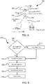
- FIG. 6 illustrates a high-level method 600 for operating aerial drone 304 ( FIGS. 3 and 5 ).
- step 605 it is decided whether or not a measurement plan needs to be created for a particular stadium. If a measurement plan creation method, such as the method described below, has not yet been used for the stadium to be surveyed, or if a measurement plan has been created but the relevant configuration parameters, including surface geometry and fixed camera positions, have changed, then a measurement plan needs to be created at step 610. Otherwise, the preexisting digital measurement plan is loaded in a pre-flight procedure at step 615. Other pre-flight tasks may include: charged battery installation, sensor calibration, safe takeoff positioning, system checks, and safety procedures.
- Aerial drone 304 FIGS.
- Aerial drone 304 takes off, executes the measurement plan at step 620 and lands.
- a post-flight procedure is performed.
- the post-flight procedure may include: disarming aerial drone 304, performing system checks, and shutting down.
- data analysis and reporting of results may be performed.
- the measurement plan can be created by first using aerial drone 304 ( FIGS. 3 and 5 ) as a positioning and angle measuring tool.
- aerial drone 304 FIGS. 3 and 5
- FIG. 7 to systematically align aerial drone 304 to each fixed and field camera (see, e.g., fixed camera 312 of FIG. 3 ), a scope 700 or other sighting system can be first mounted to aerial drone 304 and its mounting position and orientation, relative to the drone's coordinate system (see FIG. 4 ), calculated.
- FIG. 7 depicts scope 700 mounted to the top of aerial drone 304, allowing the aerial drone to be held and aimed in a manner similar to holding a rifle.
- a user can then look through scope 700 and orient aerial drone 304 to bring a targeted camera (such as fixed camera 312) into view/coaxial alignment.
- a targeted camera such as fixed camera 312
- the resulting telemetry data provides the absolute yaw and pitch angle to the camera with respect to the absolute position of aerial drone 304.
- a button, switch, or other device can also be used to aid in tagging telemetry data when aimed for later identification in the telemetry log.
- the roll angle of aerial drone 304 is used to correct the yaw and pitch angle calculations and is not otherwise recorded in the measurement plan, as during flight the aerial drone is held level with the ground while taking light measurements.
- aerial drone 304 is used to measure the absolute position of at least three corners of playing surface 300A ( FIG. 3 ) using a positioning sensor, such as a GPS sensor or local reference sensor, possibly data fused with other localization sensor(s) (for instance, IMU).
- a positioning sensor such as a GPS sensor or local reference sensor, possibly data fused with other localization sensor(s) (for instance, IMU).
- IMU localization sensor
- GCS 508 FIG. 5
- FIG. 4 illustrates example flight path 408.
- aerial drone 304 stops at each measurement position 404, adjusts its yaw and/or gimbal angle to take each measurement, records the measurements, and then moves to the next measurement position.
- Forms of analysis and reporting may include any one or more of the following, among others: tabulated illumination readings, possibly divided according to some dimension (for instance, a fixed or field camera); statistical analysis; problem/anomaly detection; and graphical charts.
- aerial drone 304 ( FIGS. 3 , 5 , and 7 ) shown in the drawings has an uncommon "Y6" airframe configuration with a side-mounted gimbal mount 512, which provides an unobstructed 180° vertical field-of-view and, thus, the flexibility to measure at any angle.
- scope 700 ( FIG. 7 )
- a duel propeller system 800 per arm 804(1) to 804(3) is used for redundancy and safety.
- FIG. 8 also illustrates a set of roll, pitch, and yaw axes 808R, 808P, and 808Y, respectively, as well as exemplar local and global reference frames 812 and 816, respectively.
- a terrestrial mobile robot can be used.
- a disadvantage of using a terrestrial mobile robot is the physical contact with playing surface 300A ( FIG. 3 ) and potential ground damage. The risk of damage depends on the locomotion mechanism and may increase with speed, especially when turning (as is the case, for instance, with skid steering).
- Another disadvantage is that if the survey requires light measurements at varying heights/ altitudes above the ground, a robot may need to employ a motorized mechanism to achieve this capability, in a limited sense. That is, not all heights will be achievable.
- transportation of a terrestrial mobile robot, which is generally larger and heavier than an aerial drone, to/from a stadium or other targeted space may be more cumbersome.
- a typical advantage of a terrestrial mobile robot is larger payload and operating time.
- the former means that potentially a more comprehensive light-measuring sensor or set of sensors, for example, a spectrophotometer that measures light intensity as a function of wavelength, can be employed more readily.
- a terrestrial mobile robot can be safer.
- a method of using a terrestrial mobile robot would be similar to that outlined above but with some distinct differences.
- a ground path would need to be devised that takes into consideration any turning circle and kinodynamic constraints of the particular locomotion mechanism used.
- a ground path would be closely coupled to a particular robot platform resulting in less hardware flexibility, especially when considering a universal approach.
- Another difference concerns the light-measuring sensor mount and angle and height control. The light-measuring sensor may need to be mounted on a turret, gimbal, robot arm, and/or other motorized mechanism to provide the required control.
- a further difference is in the initial ground path setup.
- a terrestrial mobile robot may not be as easily or quickly moved manually.
- using birds-eye imagery, for example, satellite imagery, and on-board sensor(s) that can measure angles to stadium cameras using image processing (passive approach) or beacon detection (requiring infrastructure) can be beneficial in terms of a more automated setup.
- any one or more of the aspects and embodiments described herein may be conveniently implemented using one or more machines (e.g., one or more computing devices that are utilized as a user computing device for an electronic document, one or more server devices, such as a document server, etc.) programmed according to the teachings of the present specification, as will be apparent to those of ordinary skill in the computer art.
- Appropriate software coding can readily be prepared by skilled programmers based on the teachings of the present disclosure, as will be apparent to those of ordinary skill in the software art.
- Aspects and implementations discussed above employing software and/or software modules may also include appropriate hardware for assisting in the implementation of the machine executable instructions of the software and/or software module.
- Such software may be a computer program product that employs a machine-readable storage medium.
- a machine-readable storage medium may be any medium that is capable of storing and/or encoding a sequence of instructions for execution by a machine (e.g., a computing device) and that causes the machine to perform any one of the methodologies and/or embodiments described herein. Examples of a machine-readable storage medium include, but are not limited to, a magnetic disk, an optical disc (e.g., CD, CD-R, DVD, DVD-R, etc.), a magneto-optical disk, a read-only memory "ROM” device, a random access memory "RAM” device, a magnetic card, an optical card, a solid-state memory device, an EPROM, an EEPROM, and any combinations thereof.
- a machine-readable medium is intended to include a single medium as well as a collection of physically separate media, such as, for example, a collection of compact discs or one or more hard disk drives in combination with a computer memory.
- a machine-readable storage medium does not include transitory forms of signal transmission.
- Such software may also include information (e.g., data) carried as a data signal on a data carrier, such as a carrier wave.
- a data carrier such as a carrier wave.
- machine-executable information may be included as a data-carrying signal embodied in a data carrier in which the signal encodes a sequence of instruction, or portion thereof, for execution by a machine (e.g., a computing device) and any related information (e.g., data structures and data) that causes the machine to perform any one of the methodologies and/or embodiments described herein.
- Examples of a computing device include, but are not limited to, an electronic book reading device, a computer workstation, a terminal computer, a server computer, a handheld device (e.g., a tablet computer, a smartphone, etc.), a web appliance, a network router, a network switch, a network bridge, any machine capable of executing a sequence of instructions that specify an action to be taken by that machine, and any combinations thereof.
- a computing device may include and/or be included in a kiosk.
- FIG. 9 shows a diagrammatic representation of one embodiment of a computing device in the example form of a computer system 900 within which a set of instructions may be executed for causing a system, such as any one or more of systems 200, 216, and 500 of FIGS. 2 and 5 , and/or portion(s) and/or combinations thereof, to perform any one or more of the aspects and/or methodologies of the present disclosure, such as method 100 of FIG. 1 and method 600 of FIG 6 . It is also contemplated that multiple computing devices may be utilized to implement a specially configured set of instructions for causing one or more of the devices to perform any one or more of the aspects and/or methodologies of the present disclosure.
- Computer system 900 includes a processor 904 and a memory 908 that communicate with each other, and with other components, via a bus 912.
- Bus 912 may include any of several types of bus structures including, but not limited to, a memory bus, a memory controller, a peripheral bus, a local bus, and any combinations thereof, using any of a variety of bus architectures.
- Memory 908 may include various components (e.g., machine-readable media) including, but not limited to, a random access memory component, a read-only component, and any combinations thereof.
- a basic input/output system 916 (BIOS), including basic routines that help to transfer information between elements within computer system 900, such as during start-up, may be stored in memory 908.
- BIOS basic input/output system
- Memory 908 may also include (e.g., stored on one or more machine-readable media) instructions (e.g., software) 920 embodying any one or more of the aspects and/or methodologies of the present disclosure.
- memory 908 may further include any number of program modules including, but not limited to, an operating system, one or more application programs, other program modules, program data, and any combinations thereof.
- Computer system 900 may also include a storage device 924.
- a storage device e.g., storage device 924
- Examples of a storage device include, but are not limited to, a hard disk drive, a magnetic disk drive, an optical disc drive in combination with an optical medium, a solid-state memory device, and any combinations thereof.
- Storage device 924 may be connected to bus 912 by an appropriate interface (not shown).
- Example interfaces include, but are not limited to, SCSI, advanced technology attachment (ATA), serial ATA, universal serial bus (USB), IEEE 1394 (FIREWIRE), and any combinations thereof.
- storage device 924 (or one or more components thereof) may be removably interfaced with computer system 900 (e.g., via an external port connector (not shown)).
- storage device 924 and an associated machine-readable medium 928 may provide nonvolatile and/or volatile storage of machine-readable instructions, data structures, program modules, and/or other data for computer system 900.
- software 920 may reside, completely or partially, within machine-readable medium 928. In another example, software 920 may reside, completely or partially, within processor 904.
- Computer system 900 may also include an input device 932.
- a user of computer system 900 may enter commands and/or other information into computer system 900 via input device 932.
- Examples of an input device 932 include, but are not limited to, an alpha-numeric input device (e.g., a keyboard), a pointing device, a joystick, a gamepad, an audio input device (e.g., a microphone, a voice response system, etc.), a cursor control device (e.g., a mouse), a touchpad, an optical scanner, a video capture device (e.g., a still camera, a video camera), a touchscreen, and any combinations thereof.
- an alpha-numeric input device e.g., a keyboard
- a pointing device e.g., a joystick, a gamepad
- an audio input device e.g., a microphone, a voice response system, etc.
- a cursor control device e.g., a
- Input device 932 may be interfaced to bus 912 via any of a variety of interfaces (not shown) including, but not limited to, a serial interface, a parallel interface, a game port, a USB interface, a FIREWIRE interface, a direct interface to bus 912, and any combinations thereof.
- Input device 932 may include a touch screen interface that may be a part of or separate from display 936, discussed further below.
- Input device 932 may be utilized as a user selection device for selecting one or more graphical representations in a graphical interface as described above.
- a user may also input commands and/or other information to computer system 900 via storage device 924 (e.g., a removable disk drive, a flash drive, etc.) and/or network interface device 940.
- a network interface device such as network interface device 940, may be utilized for connecting computer system 900 to one or more of a variety of networks, such as network 944, and one or more remote devices 948 connected thereto. Examples of a network interface device include, but are not limited to, a network interface card (e.g., a mobile network interface card, a LAN card), a modem, and any combination thereof.
- Examples of a network include, but are not limited to, a wide area network (e.g., the Internet, an enterprise network), a local area network (e.g., a network associated with an office, a building, a campus or other relatively small geographic space), a telephone network, a data network associated with a telephone/voice provider (e.g., a mobile communications provider data and/or voice network), a direct connection between two computing devices, and any combinations thereof.
- a network such as network 944, may employ a wired and/or a wireless mode of communication. In general, any network topology may be used.
- Information e.g., data, software 920, etc.
- Computer system 900 may further include a video display adapter 952 for communicating a displayable image to a display device, such as display device 936.
- a display device include, but are not limited to, a liquid crystal display (LCD), a cathode ray tube (CRT), a plasma display, a light emitting diode (LED) display, and any combinations thereof.
- Display adapter 952 and display device 936 may be utilized in combination with processor 904 to provide graphical representations of aspects of the present disclosure.
- computer system 900 may include one or more other peripheral output devices including, but not limited to, an audio speaker, a printer, and any combinations thereof.
- peripheral output devices may be connected to bus 912 via a peripheral interface 956. Examples of a peripheral interface include, but are not limited to, a serial port, a USB connection, a FIREWIRE connection, a parallel connection, and any combinations thereof.
- the methods and systems described herein are not limited to a particular hardware or software configuration, and may find applicability in many computing or processing environments.
- the methods and systems may be implemented in hardware or software, or a combination of hardware and software.
- the methods and systems may be implemented in one or more computer programs, where a computer program may be understood to include one or more processor executable instructions.
- the computer program(s) may execute on one or more programmable processors, and may be stored on one or more storage medium readable by the processor (including volatile and non-volatile memory and/or storage elements), one or more input devices, and/or one or more output devices.
- the processor thus may access one or more input devices to obtain input data, and may access one or more output devices to communicate output data.
- the input and/or output devices may include one or more of the following: Random Access Memory (RAM), Redundant Array of Independent Disks (RAID), floppy drive, CD, DVD, magnetic disk, internal hard drive, external hard drive, memory stick, or other storage device capable of being accessed by a processor as provided herein, where such aforementioned examples are not exhaustive, and are for illustration and not limitation.
- RAM Random Access Memory
- RAID Redundant Array of Independent Disks
- floppy drive CD, DVD, magnetic disk, internal hard drive, external hard drive, memory stick, or other storage device capable of being accessed by a processor as provided herein, where such aforementioned examples are not exhaustive, and are for illustration and not limitation.
- the computer program(s) may be implemented using one or more high level procedural or object-oriented programming languages to communicate with a computer system; however, the program(s) may be implemented in assembly or machine language, if desired.
- the language may be compiled or interpreted.
- the processor(s) may thus be embedded in one or more devices that may be operated independently or together in a networked environment, where the network may include, for example, a Local Area Network (LAN), wide area network (WAN), and/or may include an intranet and/or the internet and/or another network.
- the network(s) may be wired or wireless or a combination thereof and may use one or more communications protocols to facilitate communications between the different processors.
- the processors may be configured for distributed processing and may utilize, in some embodiments, a client-server model as needed. Accordingly, the methods and systems may utilize multiple processors and/or processor devices, and the processor instructions may be divided amongst such single- or multiple-processor/devices.
- the device(s) or computer systems that integrate with the processor(s) may include, for example, a personal computer(s), workstation(s) (e.g., Sun, HP), personal digital assistant(s) (PDA(s)), handheld device(s) such as cellular telephone(s) or smart cellphone(s), laptop(s), handheld computer(s), or another device(s) capable of being integrated with a processor(s) that may operate as provided herein. Accordingly, the devices provided herein are not exhaustive and are provided for illustration and not limitation.
- references to "a microprocessor” and “a processor”, or “the microprocessor” and “the processor,” may be understood to include one or more microprocessors that may communicate in a stand-alone and/or a distributed environment(s), and may thus be configured to communicate via wired or wireless communications with other processors, where such one or more processor may be configured to operate on one or more processor-controlled devices that may be similar or different devices.
- Use of such "microprocessor” or “processor” terminology may thus also be understood to include a central processing unit, an arithmetic logic unit, an application-specific integrated circuit (IC), and/or a task engine, with such examples provided for illustration and not limitation.
- references to memory may include one or more processor-readable and accessible memory elements and/or components that may be internal to the processor-controlled device, external to the processor-controlled device, and/or may be accessed via a wired or wireless network using a variety of communications protocols, and unless otherwise specified, may be arranged to include a combination of external and internal memory devices, where such memory may be contiguous and/or partitioned based on the application.
- references to a database may be understood to include one or more memory associations, where such references may include commercially available database products (e.g., SQL, Informix, Oracle) and also proprietary databases, and may also include other structures for associating memory such as links, queues, graphs, trees, with such structures provided for illustration and not limitation.
- references to a network may include one or more intranets and/or the internet.
- References herein to microprocessor instructions or microprocessor-executable instructions, in accordance with the above, may be understood to include programmable hardware.
Landscapes
- Physics & Mathematics (AREA)
- General Physics & Mathematics (AREA)
- Spectroscopy & Molecular Physics (AREA)
- Engineering & Computer Science (AREA)
- Aviation & Aerospace Engineering (AREA)
- Life Sciences & Earth Sciences (AREA)
- Sustainable Development (AREA)
- Radar, Positioning & Navigation (AREA)
- Remote Sensing (AREA)
- Automation & Control Theory (AREA)
- Traffic Control Systems (AREA)
- Testing Or Calibration Of Command Recording Devices (AREA)
Claims (14)
- Verfahren zum Vornehmen von Lichtmessungsablesungen innerhalb eines Zielraums, umfassend:Empfangen, für den Einsatz eines autonomen Fahrzeugs (208) mit einem Lichtmesssensor (212, 308), eines Lichtmessplans (204), der eine Identifikation mehrerer Messpositionen (404) für das autonome Fahrzeug im Zielraum beinhaltet;Veranlassen, dass sich das autonome Fahrzeug (208) basierend auf dem Lichtmessplan (204) automatisch zu jeder der Messpositionen (404) bewegt;Veranlassen, dass der Lichtmesssensor (212, 308) die Lichtmessung an jeder der Messpositionen (404) erfasst, während sich das autonome Fahrzeug (208) basierend auf dem Lichtmessplan (204) an der entsprechenden der Messpositionen befindet; undSpeichern, für jede Messposition (404), der an dieser Position vorgenommenen Lichtmessung und Informationen, die diese Position identifizieren;wobei der Lichtmessplan (204) einen Weg beinhaltet, der die Messpositionen (404) durchquert, dadurch gekennzeichnet, dass das Verfahren ferner umfasst:
Bestimmen des Wegs basierend auf dem Einsatz des autonomen Fahrzeuges (208) vor einem Ausführen des Lichtmessplanes. - Verfahren nach Anspruch 1, wobei der Zielraum eine Beleuchtungsspezifikation aufweist, die die mehreren Messpositionen und einen entsprechenden Ziel-Lichtmesswert an jeder der Messpositionen beinhaltet.
- Verfahren nach Anspruch 2, ferner umfassend das automatische Vergleichen jeder vorgenommenen Lichtmessung mit dem entsprechenden Ziel-Lichtmesswert.
- Verfahren nach Anspruch 2, wobei der Zielraum ein Spielfeld ist und die Beleuchtungsspezifikation eine FIFA-Beleuchtungsspezifikation ist.
- Verfahren nach Anspruch 1, wobei das autonome Fahrzeug (208) ein Luftfahrzeug umfasst und der Lichtmessplan (204) einen Flugweg (408) für das Luftfahrzeug beinhaltet, der einen Weg durchquert, der die mehreren Messpositionen (404) beinhaltet.
- Verfahren nach Anspruch 1, wobei das autonome Fahrzeug (208) ein terrestrisches Fahrzeug umfasst und der Lichtmessplan (204) eine terrestrische Route beinhaltet, die einen Weg durchquert, der die mehreren Messpositionen (404) beinhaltet.
- Verfahren nach Anspruch 1, wobei das autonome Fahrzeug (208) ein Wasserfahrzeug umfasst und der Lichtmessplan (204) eine wasserbasierte Route beinhaltet, die einen Weg durchquert, der die mehreren Messpositionen (404) beinhaltet.
- Verfahren nach Anspruch 1, ferner umfassend das Bewegen des autonomen Fahrzeugs (208) zu jeder der Messpositionen (404) unter Verwendung von Echtzeit-Positionierungsinformationen.
- Verfahren nach Anspruch 1, ferner umfassend das Bewegen des autonomen Fahrzeugs (208) zu jeder der Messpositionen (404) basierend auf einer lokalen Positionierungsreferenz.
- Verfahren nach Anspruch 1, ferner umfassend das Steuern des autonomen Fahrzeugs (208) und/oder einer beweglichen Halterung, um ein Ziel für einen Lichtmesssensor zu erreichen.
- Nicht flüchtiges maschinenlesbares Speichermedium, das maschinenausführbare Anweisungen enthält, die konfiguriert sind, um einen Prozessor (232) eines Lichtmesssystems zu veranlassen, das Verfahren nach einem der Ansprüche 1 bis 10 durchzuführen.
- Lichtmesssystem, um Lichtmessungen innerhalb eines Zielraums vorzunehmen, wobei das System umfasst:ein autonomes Fahrzeug (208), das ein Fortbewegungssystem beinhaltet, das in der Lage ist, das autonome Fahrzeug so zu bewegen, dass es einen Weg zurücklegt, der Messpositionen (404) innerhalb des Zielraums beinhaltet;einen Lichtmesssensor (212, 308), der am autonomen Fahrzeug (208) eingesetzt wird, um die Lichtmessung an jeder der Messpositionen (404) zu erfassen; undein Messplan-(204)-System, das konfiguriert ist, um einen Messplan zu implementieren, um die Lichtmessungen an den Messpositionen (404) zu erfassen,wobei das Messplan-System umfasst:Navigationsanweisungen, die konfiguriert sind, um das Fortbewegungssystem zu veranlassen, das autonome Fahrzeug (208) so zu bewegen, dass es den Weg zurücklegt; undSensor-(212, 308)-Anweisungen, die konfiguriert sind, um den Lichtmesssensor zu veranlassen, die Lichtmessung an jeder der Messpositionen (404) zu erfassen;wobei der Lichtmessplan (204) einen Weg beinhaltet, der die Messpositionen (404) durchquert, dadurch gekennzeichnet, dass das Lichtmesssystem konfiguriert ist, um den Weg basierend auf einem Einsatz des autonomen Fahrzeugs (208) vor dem Ausführen der Lichtmessung zu bestimmen.
- Lichtmesssystem nach Anspruch 12, wobei das autonome Fahrzeug (208) ferner einen globalen Positionierungssystemempfänger umfasst, und die Navigationsanweisungen das Fortbewegungssystem veranlassen, das autonome Fahrzeug so zu bewegen, dass es den Weg basierend auf globalen Positionierungssysteminformationen, die vom globalen Positionierungssystemempfänger erfasst werden, zurücklegt; oder
wobei das autonome Fahrzeug (208) ferner ein Positionierungssystem umfasst, das dem autonomen Fahrzeug erlaubt, jede Messposition (404) basierend auf einer lokalen Positionierungsreferenz zu identifizieren. - Lichtmesssystem nach Anspruch 12, wobei der Lichtmesssensor (212, 308) beweglich am autonomen Fahrzeug (208) montiert ist, und die Sensoranweisungen Anweisungen beinhalten, um den Lichtmesssensor relativ zum autonomen Fahrzeug zu bewegen.
Applications Claiming Priority (3)
| Application Number | Priority Date | Filing Date | Title |
|---|---|---|---|
| US201662395311P | 2016-09-15 | 2016-09-15 | |
| US15/705,106 US10928245B2 (en) | 2016-09-15 | 2017-09-14 | Light measurement using an autonomous vehicle |
| PCT/US2017/051932 WO2018053370A1 (en) | 2016-09-15 | 2017-09-15 | Light measurement using an autonomous vehicle |
Publications (2)
| Publication Number | Publication Date |
|---|---|
| EP3513264A1 EP3513264A1 (de) | 2019-07-24 |
| EP3513264B1 true EP3513264B1 (de) | 2022-07-27 |
Family
ID=61559736
Family Applications (1)
| Application Number | Title | Priority Date | Filing Date |
|---|---|---|---|
| EP17784070.9A Active EP3513264B1 (de) | 2016-09-15 | 2017-09-15 | Lichtmessung mit verwwendung eines autonomen fahrzeugs |
Country Status (4)
| Country | Link |
|---|---|
| US (1) | US10928245B2 (de) |
| EP (1) | EP3513264B1 (de) |
| CA (1) | CA3036081A1 (de) |
| WO (1) | WO2018053370A1 (de) |
Families Citing this family (6)
| Publication number | Priority date | Publication date | Assignee | Title |
|---|---|---|---|---|
| DE102016005403B4 (de) * | 2016-04-30 | 2018-04-26 | Diehl Metering Gmbh | Verfahren zur Kommunikation zwischen wenigstens einer Zählereinrichtung und einer Flugeinrichtung |
| US10928245B2 (en) * | 2016-09-15 | 2021-02-23 | Siteco Gmbh | Light measurement using an autonomous vehicle |
| JP7353747B2 (ja) * | 2018-01-12 | 2023-10-02 | キヤノン株式会社 | 情報処理装置、システム、方法、およびプログラム |
| US11048257B2 (en) | 2018-01-23 | 2021-06-29 | Gopro, Inc. | Relative image capture device orientation calibration |
| US11231715B2 (en) * | 2018-05-22 | 2022-01-25 | King Fahd University Of Petroleum And Minerals | Method and system for controlling a vehicle |
| CN114296475A (zh) * | 2021-12-06 | 2022-04-08 | 中国兵器科学研究院 | 一种未知空间探索系统、方法、装置、设备及介质 |
Citations (4)
| Publication number | Priority date | Publication date | Assignee | Title |
|---|---|---|---|---|
| WO2013177059A1 (en) * | 2012-05-22 | 2013-11-28 | Urbach Julian M | Portable mobile light stage |
| US20150035437A1 (en) * | 2013-08-05 | 2015-02-05 | Peter J. Panopoulos | Led lighting system |
| US20150173147A1 (en) * | 2013-12-17 | 2015-06-18 | Ephesus Lighting, Inc. | Selectable control for high intensity led illumination system to maintain constant color temperature on a lit surface |
| US20160227634A1 (en) * | 2013-09-10 | 2016-08-04 | Philips Lighting Holding B.V. | Methods and apparatus for automated commissioning of coded light sources |
Family Cites Families (18)
| Publication number | Priority date | Publication date | Assignee | Title |
|---|---|---|---|---|
| US9933297B2 (en) * | 2013-03-26 | 2018-04-03 | Sensity Systems Inc. | System and method for planning and monitoring a light sensory network |
| JP6551392B2 (ja) * | 2013-04-05 | 2019-07-31 | アンドラ モーション テクノロジーズ インク. | 画像キャプチャに関する装置を制御するシステムおよび方法 |
| EP2987390B1 (de) * | 2013-04-19 | 2017-11-01 | Philips Lighting Holding B.V. | Kalibrierungsbetrieb einer beleuchtungsvorrichtung |
| US9405972B2 (en) * | 2013-09-27 | 2016-08-02 | Qualcomm Incorporated | Exterior hybrid photo mapping |
| JP6326237B2 (ja) * | 2014-01-31 | 2018-05-16 | 株式会社トプコン | 測定システム |
| US20150234055A1 (en) * | 2014-02-20 | 2015-08-20 | Javad Gnss, Inc. | Aerial and close-range photogrammetry |
| US9581443B2 (en) * | 2014-03-17 | 2017-02-28 | Ronald D. Shaw | Surveying system |
| US9668146B2 (en) * | 2014-04-25 | 2017-05-30 | The Hong Kong University Of Science And Technology | Autonomous robot-assisted indoor wireless coverage characterization platform |
| WO2015175818A1 (en) * | 2014-05-16 | 2015-11-19 | Musco Corporation | Sports lighting to increase contrast |
| US10915673B2 (en) * | 2014-07-01 | 2021-02-09 | Scanifly, LLC | Device, method, apparatus, and computer-readable medium for solar site assessment |
| US9924578B2 (en) * | 2014-08-14 | 2018-03-20 | Philips Lighting Holding B.V. | Lighting system for a stadium |
| EP3428766B1 (de) * | 2014-09-05 | 2021-04-07 | SZ DJI Technology Co., Ltd. | Abbildung von multisensorumgebungen |
| US9470579B2 (en) * | 2014-09-08 | 2016-10-18 | SlantRange, Inc. | System and method for calibrating imaging measurements taken from aerial vehicles |
| EP3317623A1 (de) * | 2015-07-02 | 2018-05-09 | Danmarks Tekniske Universitet | Strassenlichtdetektion |
| US9651390B1 (en) * | 2016-02-25 | 2017-05-16 | Here Global B.V. | Mapping road illumination |
| US9454154B1 (en) * | 2016-03-07 | 2016-09-27 | Amazon Technologies, Inc. | Incident light sensor on autonomous vehicle |
| US20180067493A1 (en) * | 2016-09-02 | 2018-03-08 | Skyefish, Llc | Intelligent gimbal assembly and method for unmanned vehicle |
| US10928245B2 (en) * | 2016-09-15 | 2021-02-23 | Siteco Gmbh | Light measurement using an autonomous vehicle |
-
2017
- 2017-09-14 US US15/705,106 patent/US10928245B2/en active Active
- 2017-09-15 WO PCT/US2017/051932 patent/WO2018053370A1/en not_active Ceased
- 2017-09-15 EP EP17784070.9A patent/EP3513264B1/de active Active
- 2017-09-15 CA CA3036081A patent/CA3036081A1/en not_active Abandoned
Patent Citations (4)
| Publication number | Priority date | Publication date | Assignee | Title |
|---|---|---|---|---|
| WO2013177059A1 (en) * | 2012-05-22 | 2013-11-28 | Urbach Julian M | Portable mobile light stage |
| US20150035437A1 (en) * | 2013-08-05 | 2015-02-05 | Peter J. Panopoulos | Led lighting system |
| US20160227634A1 (en) * | 2013-09-10 | 2016-08-04 | Philips Lighting Holding B.V. | Methods and apparatus for automated commissioning of coded light sources |
| US20150173147A1 (en) * | 2013-12-17 | 2015-06-18 | Ephesus Lighting, Inc. | Selectable control for high intensity led illumination system to maintain constant color temperature on a lit surface |
Also Published As
| Publication number | Publication date |
|---|---|
| WO2018053370A1 (en) | 2018-03-22 |
| CA3036081A1 (en) | 2018-03-22 |
| US20180073918A1 (en) | 2018-03-15 |
| EP3513264A1 (de) | 2019-07-24 |
| US10928245B2 (en) | 2021-02-23 |
Similar Documents
| Publication | Publication Date | Title |
|---|---|---|
| US10928245B2 (en) | Light measurement using an autonomous vehicle | |
| CN113597591B (zh) | 用于无人飞行器导航的地理基准 | |
| US10382975B2 (en) | Subterranean 3D modeling at cell sites | |
| US9704292B2 (en) | Virtualized site survey systems and methods for cell sites | |
| US10187806B2 (en) | Systems and methods for obtaining accurate 3D modeling data using multiple cameras | |
| US10397802B2 (en) | Detecting changes at cell sites and surrounding areas using unmanned aerial vehicles | |
| US20230358538A1 (en) | Control Point Identification And Reuse System | |
| US10368249B2 (en) | Modeling fiber cabling associated with cell sites | |
| US10327151B2 (en) | Wireless coverage testing systems and methods with unmanned aerial vehicles | |
| US9988140B2 (en) | Counterbalancing unmanned aerial vehicles during operations associated with cell towers | |
| US9881416B2 (en) | Obtaining 3D modeling data using UAVs for cell sites | |
| US10475239B1 (en) | Systems and methods for obtaining accurate 3D modeling data with a multiple camera apparatus | |
| US9654984B2 (en) | Cell tower installation systems and methods with unmanned aerial vehicles | |
| US10227134B2 (en) | Using drones to lift personnel up cell towers | |
| US10580199B2 (en) | Systems and methods for data capture for telecommunications site modeling via a telescoping apparatus | |
| US20170046873A1 (en) | Systems and methods for obtaining accurate 3d modeling data using uavs for cell sites | |
| US10534499B2 (en) | Cell site audit and survey via photo stitching | |
| US10311565B2 (en) | Cell site equipment verification using 3D modeling comparisons | |
| US10231133B2 (en) | 3D modeling of cell sites and cell towers with unmanned aerial vehicles | |
| US10183761B2 (en) | 3D modeling of cell sites to detect configuration and site changes | |
| US10313575B1 (en) | Drone-based inspection of terrestrial assets and corresponding methods, systems, and apparatuses | |
| US20160327389A1 (en) | Calibration Transfer Between Two Devices | |
| US20160320775A1 (en) | Cell tower installation and maintenance systems and methods using robotic devices | |
| US9947135B2 (en) | Close-out audit systems and methods for cell site installation and maintenance | |
| US20200396361A1 (en) | 360 Degree Camera Apparatus with Monitoring Sensors |
Legal Events
| Date | Code | Title | Description |
|---|---|---|---|
| STAA | Information on the status of an ep patent application or granted ep patent |
Free format text: STATUS: UNKNOWN |
|
| STAA | Information on the status of an ep patent application or granted ep patent |
Free format text: STATUS: THE INTERNATIONAL PUBLICATION HAS BEEN MADE |
|
| PUAI | Public reference made under article 153(3) epc to a published international application that has entered the european phase |
Free format text: ORIGINAL CODE: 0009012 |
|
| STAA | Information on the status of an ep patent application or granted ep patent |
Free format text: STATUS: REQUEST FOR EXAMINATION WAS MADE |
|
| 17P | Request for examination filed |
Effective date: 20190214 |
|
| AK | Designated contracting states |
Kind code of ref document: A1 Designated state(s): AL AT BE BG CH CY CZ DE DK EE ES FI FR GB GR HR HU IE IS IT LI LT LU LV MC MK MT NL NO PL PT RO RS SE SI SK SM TR |
|
| AX | Request for extension of the european patent |
Extension state: BA ME |
|
| DAV | Request for validation of the european patent (deleted) | ||
| DAX | Request for extension of the european patent (deleted) | ||
| RAP1 | Party data changed (applicant data changed or rights of an application transferred) |
Owner name: SITECO GMBH |
|
| RAP1 | Party data changed (applicant data changed or rights of an application transferred) |
Owner name: SITECO GMBH |
|
| STAA | Information on the status of an ep patent application or granted ep patent |
Free format text: STATUS: EXAMINATION IS IN PROGRESS |
|
| 17Q | First examination report despatched |
Effective date: 20210208 |
|
| REG | Reference to a national code |
Ref country code: DE Ref legal event code: R079 Ref document number: 602017059922 Country of ref document: DE Free format text: PREVIOUS MAIN CLASS: G05D0001000000 Ipc: B64C0039020000 |
|
| GRAP | Despatch of communication of intention to grant a patent |
Free format text: ORIGINAL CODE: EPIDOSNIGR1 |
|
| STAA | Information on the status of an ep patent application or granted ep patent |
Free format text: STATUS: GRANT OF PATENT IS INTENDED |
|
| RIC1 | Information provided on ipc code assigned before grant |
Ipc: G05D 1/00 20060101ALI20220130BHEP Ipc: G08G 5/00 20060101ALI20220130BHEP Ipc: G01J 1/42 20060101ALI20220130BHEP Ipc: G01J 1/02 20060101ALI20220130BHEP Ipc: B64C 39/02 20060101AFI20220130BHEP |
|
| INTG | Intention to grant announced |
Effective date: 20220216 |
|
| GRAS | Grant fee paid |
Free format text: ORIGINAL CODE: EPIDOSNIGR3 |
|
| GRAA | (expected) grant |
Free format text: ORIGINAL CODE: 0009210 |
|
| STAA | Information on the status of an ep patent application or granted ep patent |
Free format text: STATUS: THE PATENT HAS BEEN GRANTED |
|
| AK | Designated contracting states |
Kind code of ref document: B1 Designated state(s): AL AT BE BG CH CY CZ DE DK EE ES FI FR GB GR HR HU IE IS IT LI LT LU LV MC MK MT NL NO PL PT RO RS SE SI SK SM TR |
|
| REG | Reference to a national code |
Ref country code: CH Ref legal event code: EP |
|
| REG | Reference to a national code |
Ref country code: DE Ref legal event code: R096 Ref document number: 602017059922 Country of ref document: DE |
|
| REG | Reference to a national code |
Ref country code: AT Ref legal event code: REF Ref document number: 1506916 Country of ref document: AT Kind code of ref document: T Effective date: 20220815 |
|
| REG | Reference to a national code |
Ref country code: IE Ref legal event code: FG4D |
|
| REG | Reference to a national code |
Ref country code: LT Ref legal event code: MG9D |
|
| REG | Reference to a national code |
Ref country code: NL Ref legal event code: MP Effective date: 20220727 |
|
| PG25 | Lapsed in a contracting state [announced via postgrant information from national office to epo] |
Ref country code: SE Free format text: LAPSE BECAUSE OF FAILURE TO SUBMIT A TRANSLATION OF THE DESCRIPTION OR TO PAY THE FEE WITHIN THE PRESCRIBED TIME-LIMIT Effective date: 20220727 Ref country code: RS Free format text: LAPSE BECAUSE OF FAILURE TO SUBMIT A TRANSLATION OF THE DESCRIPTION OR TO PAY THE FEE WITHIN THE PRESCRIBED TIME-LIMIT Effective date: 20220727 Ref country code: PT Free format text: LAPSE BECAUSE OF FAILURE TO SUBMIT A TRANSLATION OF THE DESCRIPTION OR TO PAY THE FEE WITHIN THE PRESCRIBED TIME-LIMIT Effective date: 20221128 Ref country code: NO Free format text: LAPSE BECAUSE OF FAILURE TO SUBMIT A TRANSLATION OF THE DESCRIPTION OR TO PAY THE FEE WITHIN THE PRESCRIBED TIME-LIMIT Effective date: 20221027 Ref country code: NL Free format text: LAPSE BECAUSE OF FAILURE TO SUBMIT A TRANSLATION OF THE DESCRIPTION OR TO PAY THE FEE WITHIN THE PRESCRIBED TIME-LIMIT Effective date: 20220727 Ref country code: LV Free format text: LAPSE BECAUSE OF FAILURE TO SUBMIT A TRANSLATION OF THE DESCRIPTION OR TO PAY THE FEE WITHIN THE PRESCRIBED TIME-LIMIT Effective date: 20220727 Ref country code: LT Free format text: LAPSE BECAUSE OF FAILURE TO SUBMIT A TRANSLATION OF THE DESCRIPTION OR TO PAY THE FEE WITHIN THE PRESCRIBED TIME-LIMIT Effective date: 20220727 Ref country code: FI Free format text: LAPSE BECAUSE OF FAILURE TO SUBMIT A TRANSLATION OF THE DESCRIPTION OR TO PAY THE FEE WITHIN THE PRESCRIBED TIME-LIMIT Effective date: 20220727 Ref country code: ES Free format text: LAPSE BECAUSE OF FAILURE TO SUBMIT A TRANSLATION OF THE DESCRIPTION OR TO PAY THE FEE WITHIN THE PRESCRIBED TIME-LIMIT Effective date: 20220727 |
|
| PG25 | Lapsed in a contracting state [announced via postgrant information from national office to epo] |
Ref country code: PL Free format text: LAPSE BECAUSE OF FAILURE TO SUBMIT A TRANSLATION OF THE DESCRIPTION OR TO PAY THE FEE WITHIN THE PRESCRIBED TIME-LIMIT Effective date: 20220727 Ref country code: IS Free format text: LAPSE BECAUSE OF FAILURE TO SUBMIT A TRANSLATION OF THE DESCRIPTION OR TO PAY THE FEE WITHIN THE PRESCRIBED TIME-LIMIT Effective date: 20221127 Ref country code: HR Free format text: LAPSE BECAUSE OF FAILURE TO SUBMIT A TRANSLATION OF THE DESCRIPTION OR TO PAY THE FEE WITHIN THE PRESCRIBED TIME-LIMIT Effective date: 20220727 Ref country code: GR Free format text: LAPSE BECAUSE OF FAILURE TO SUBMIT A TRANSLATION OF THE DESCRIPTION OR TO PAY THE FEE WITHIN THE PRESCRIBED TIME-LIMIT Effective date: 20221028 |
|
| PG25 | Lapsed in a contracting state [announced via postgrant information from national office to epo] |
Ref country code: SM Free format text: LAPSE BECAUSE OF FAILURE TO SUBMIT A TRANSLATION OF THE DESCRIPTION OR TO PAY THE FEE WITHIN THE PRESCRIBED TIME-LIMIT Effective date: 20220727 Ref country code: RO Free format text: LAPSE BECAUSE OF FAILURE TO SUBMIT A TRANSLATION OF THE DESCRIPTION OR TO PAY THE FEE WITHIN THE PRESCRIBED TIME-LIMIT Effective date: 20220727 Ref country code: MC Free format text: LAPSE BECAUSE OF FAILURE TO SUBMIT A TRANSLATION OF THE DESCRIPTION OR TO PAY THE FEE WITHIN THE PRESCRIBED TIME-LIMIT Effective date: 20220727 Ref country code: DK Free format text: LAPSE BECAUSE OF FAILURE TO SUBMIT A TRANSLATION OF THE DESCRIPTION OR TO PAY THE FEE WITHIN THE PRESCRIBED TIME-LIMIT Effective date: 20220727 Ref country code: CZ Free format text: LAPSE BECAUSE OF FAILURE TO SUBMIT A TRANSLATION OF THE DESCRIPTION OR TO PAY THE FEE WITHIN THE PRESCRIBED TIME-LIMIT Effective date: 20220727 |
|
| REG | Reference to a national code |
Ref country code: DE Ref legal event code: R097 Ref document number: 602017059922 Country of ref document: DE |
|
| REG | Reference to a national code |
Ref country code: BE Ref legal event code: MM Effective date: 20220930 |
|
| PG25 | Lapsed in a contracting state [announced via postgrant information from national office to epo] |
Ref country code: SK Free format text: LAPSE BECAUSE OF FAILURE TO SUBMIT A TRANSLATION OF THE DESCRIPTION OR TO PAY THE FEE WITHIN THE PRESCRIBED TIME-LIMIT Effective date: 20220727 Ref country code: EE Free format text: LAPSE BECAUSE OF FAILURE TO SUBMIT A TRANSLATION OF THE DESCRIPTION OR TO PAY THE FEE WITHIN THE PRESCRIBED TIME-LIMIT Effective date: 20220727 |
|
| PLBE | No opposition filed within time limit |
Free format text: ORIGINAL CODE: 0009261 |
|
| STAA | Information on the status of an ep patent application or granted ep patent |
Free format text: STATUS: NO OPPOSITION FILED WITHIN TIME LIMIT |
|
| PG25 | Lapsed in a contracting state [announced via postgrant information from national office to epo] |
Ref country code: LU Free format text: LAPSE BECAUSE OF NON-PAYMENT OF DUE FEES Effective date: 20220915 Ref country code: AL Free format text: LAPSE BECAUSE OF FAILURE TO SUBMIT A TRANSLATION OF THE DESCRIPTION OR TO PAY THE FEE WITHIN THE PRESCRIBED TIME-LIMIT Effective date: 20220727 |
|
| 26N | No opposition filed |
Effective date: 20230502 |
|
| PG25 | Lapsed in a contracting state [announced via postgrant information from national office to epo] |
Ref country code: IE Free format text: LAPSE BECAUSE OF NON-PAYMENT OF DUE FEES Effective date: 20220915 Ref country code: FR Free format text: LAPSE BECAUSE OF NON-PAYMENT OF DUE FEES Effective date: 20220927 |
|
| PG25 | Lapsed in a contracting state [announced via postgrant information from national office to epo] |
Ref country code: SI Free format text: LAPSE BECAUSE OF FAILURE TO SUBMIT A TRANSLATION OF THE DESCRIPTION OR TO PAY THE FEE WITHIN THE PRESCRIBED TIME-LIMIT Effective date: 20220727 |
|
| PG25 | Lapsed in a contracting state [announced via postgrant information from national office to epo] |
Ref country code: BE Free format text: LAPSE BECAUSE OF NON-PAYMENT OF DUE FEES Effective date: 20220930 |
|
| REG | Reference to a national code |
Ref country code: AT Ref legal event code: UEP Ref document number: 1506916 Country of ref document: AT Kind code of ref document: T Effective date: 20220727 |
|
| PG25 | Lapsed in a contracting state [announced via postgrant information from national office to epo] |
Ref country code: HU Free format text: LAPSE BECAUSE OF FAILURE TO SUBMIT A TRANSLATION OF THE DESCRIPTION OR TO PAY THE FEE WITHIN THE PRESCRIBED TIME-LIMIT; INVALID AB INITIO Effective date: 20170915 |
|
| PG25 | Lapsed in a contracting state [announced via postgrant information from national office to epo] |
Ref country code: CY Free format text: LAPSE BECAUSE OF FAILURE TO SUBMIT A TRANSLATION OF THE DESCRIPTION OR TO PAY THE FEE WITHIN THE PRESCRIBED TIME-LIMIT Effective date: 20220727 |
|
| PG25 | Lapsed in a contracting state [announced via postgrant information from national office to epo] |
Ref country code: MK Free format text: LAPSE BECAUSE OF FAILURE TO SUBMIT A TRANSLATION OF THE DESCRIPTION OR TO PAY THE FEE WITHIN THE PRESCRIBED TIME-LIMIT Effective date: 20220727 Ref country code: IT Free format text: LAPSE BECAUSE OF FAILURE TO SUBMIT A TRANSLATION OF THE DESCRIPTION OR TO PAY THE FEE WITHIN THE PRESCRIBED TIME-LIMIT Effective date: 20220727 |
|
| PG25 | Lapsed in a contracting state [announced via postgrant information from national office to epo] |
Ref country code: BG Free format text: LAPSE BECAUSE OF FAILURE TO SUBMIT A TRANSLATION OF THE DESCRIPTION OR TO PAY THE FEE WITHIN THE PRESCRIBED TIME-LIMIT Effective date: 20220727 |
|
| PG25 | Lapsed in a contracting state [announced via postgrant information from national office to epo] |
Ref country code: MT Free format text: LAPSE BECAUSE OF FAILURE TO SUBMIT A TRANSLATION OF THE DESCRIPTION OR TO PAY THE FEE WITHIN THE PRESCRIBED TIME-LIMIT Effective date: 20220727 |
|
| REG | Reference to a national code |
Ref country code: CH Ref legal event code: U11 Free format text: ST27 STATUS EVENT CODE: U-0-0-U10-U11 (AS PROVIDED BY THE NATIONAL OFFICE) Effective date: 20251001 |
|
| PGFP | Annual fee paid to national office [announced via postgrant information from national office to epo] |
Ref country code: DE Payment date: 20250919 Year of fee payment: 9 |
|
| PGFP | Annual fee paid to national office [announced via postgrant information from national office to epo] |
Ref country code: GB Payment date: 20250923 Year of fee payment: 9 |
|
| PGFP | Annual fee paid to national office [announced via postgrant information from national office to epo] |
Ref country code: AT Payment date: 20250918 Year of fee payment: 9 |
|
| PG25 | Lapsed in a contracting state [announced via postgrant information from national office to epo] |
Ref country code: TR Free format text: LAPSE BECAUSE OF FAILURE TO SUBMIT A TRANSLATION OF THE DESCRIPTION OR TO PAY THE FEE WITHIN THE PRESCRIBED TIME-LIMIT Effective date: 20220727 |
|
| PGFP | Annual fee paid to national office [announced via postgrant information from national office to epo] |
Ref country code: CH Payment date: 20251001 Year of fee payment: 9 |