EP3513243B1 - Optical system for head-mounted display system - Google Patents
Optical system for head-mounted display system Download PDFInfo
- Publication number
- EP3513243B1 EP3513243B1 EP17851535.9A EP17851535A EP3513243B1 EP 3513243 B1 EP3513243 B1 EP 3513243B1 EP 17851535 A EP17851535 A EP 17851535A EP 3513243 B1 EP3513243 B1 EP 3513243B1
- Authority
- EP
- European Patent Office
- Prior art keywords
- fresnel
- zone
- optical system
- features
- pattern
- Prior art date
- Legal status (The legal status is an assumption and is not a legal conclusion. Google has not performed a legal analysis and makes no representation as to the accuracy of the status listed.)
- Active
Links
- 230000003287 optical effect Effects 0.000 title claims description 46
- 230000007704 transition Effects 0.000 claims description 13
- 230000004075 alteration Effects 0.000 claims description 12
- 230000002093 peripheral effect Effects 0.000 claims description 4
- 239000011295 pitch Substances 0.000 description 23
- 238000000034 method Methods 0.000 description 4
- XUIMIQQOPSSXEZ-UHFFFAOYSA-N Silicon Chemical compound [Si] XUIMIQQOPSSXEZ-UHFFFAOYSA-N 0.000 description 3
- 230000003190 augmentative effect Effects 0.000 description 3
- 210000003128 head Anatomy 0.000 description 3
- 229910052710 silicon Inorganic materials 0.000 description 3
- 239000010703 silicon Substances 0.000 description 3
- 208000013057 hereditary mucoepithelial dysplasia Diseases 0.000 description 2
- 239000000463 material Substances 0.000 description 2
- 210000001747 pupil Anatomy 0.000 description 2
- 230000003247 decreasing effect Effects 0.000 description 1
- 230000001419 dependent effect Effects 0.000 description 1
- 210000005069 ears Anatomy 0.000 description 1
- 238000005516 engineering process Methods 0.000 description 1
- 239000011521 glass Substances 0.000 description 1
- 239000004973 liquid crystal related substance Substances 0.000 description 1
- 238000004519 manufacturing process Methods 0.000 description 1
- 238000002156 mixing Methods 0.000 description 1
- 230000000737 periodic effect Effects 0.000 description 1
Images
Classifications
-
- G—PHYSICS
- G02—OPTICS
- G02B—OPTICAL ELEMENTS, SYSTEMS OR APPARATUS
- G02B27/00—Optical systems or apparatus not provided for by any of the groups G02B1/00 - G02B26/00, G02B30/00
- G02B27/01—Head-up displays
- G02B27/017—Head mounted
- G02B27/0172—Head mounted characterised by optical features
-
- G—PHYSICS
- G02—OPTICS
- G02B—OPTICAL ELEMENTS, SYSTEMS OR APPARATUS
- G02B3/00—Simple or compound lenses
- G02B3/02—Simple or compound lenses with non-spherical faces
- G02B3/08—Simple or compound lenses with non-spherical faces with discontinuous faces, e.g. Fresnel lens
-
- G—PHYSICS
- G02—OPTICS
- G02B—OPTICAL ELEMENTS, SYSTEMS OR APPARATUS
- G02B25/00—Eyepieces; Magnifying glasses
- G02B25/001—Eyepieces
-
- G—PHYSICS
- G02—OPTICS
- G02B—OPTICAL ELEMENTS, SYSTEMS OR APPARATUS
- G02B27/00—Optical systems or apparatus not provided for by any of the groups G02B1/00 - G02B26/00, G02B30/00
- G02B27/42—Diffraction optics, i.e. systems including a diffractive element being designed for providing a diffractive effect
- G02B27/4205—Diffraction optics, i.e. systems including a diffractive element being designed for providing a diffractive effect having a diffractive optical element [DOE] contributing to image formation, e.g. whereby modulation transfer function MTF or optical aberrations are relevant
- G02B27/4216—Diffraction optics, i.e. systems including a diffractive element being designed for providing a diffractive effect having a diffractive optical element [DOE] contributing to image formation, e.g. whereby modulation transfer function MTF or optical aberrations are relevant correcting geometrical aberrations
-
- G—PHYSICS
- G02—OPTICS
- G02B—OPTICAL ELEMENTS, SYSTEMS OR APPARATUS
- G02B3/00—Simple or compound lenses
- G02B3/02—Simple or compound lenses with non-spherical faces
- G02B3/04—Simple or compound lenses with non-spherical faces with continuous faces that are rotationally symmetrical but deviate from a true sphere, e.g. so called "aspheric" lenses
-
- G—PHYSICS
- G02—OPTICS
- G02B—OPTICAL ELEMENTS, SYSTEMS OR APPARATUS
- G02B5/00—Optical elements other than lenses
- G02B5/18—Diffraction gratings
- G02B5/1876—Diffractive Fresnel lenses; Zone plates; Kinoforms
- G02B5/189—Structurally combined with optical elements not having diffractive power
- G02B5/1895—Structurally combined with optical elements not having diffractive power such optical elements having dioptric power
-
- G—PHYSICS
- G02—OPTICS
- G02B—OPTICAL ELEMENTS, SYSTEMS OR APPARATUS
- G02B27/00—Optical systems or apparatus not provided for by any of the groups G02B1/00 - G02B26/00, G02B30/00
- G02B27/01—Head-up displays
- G02B27/0101—Head-up displays characterised by optical features
- G02B2027/011—Head-up displays characterised by optical features comprising device for correcting geometrical aberrations, distortion
-
- G—PHYSICS
- G02—OPTICS
- G02B—OPTICAL ELEMENTS, SYSTEMS OR APPARATUS
- G02B27/00—Optical systems or apparatus not provided for by any of the groups G02B1/00 - G02B26/00, G02B30/00
- G02B27/01—Head-up displays
- G02B27/0101—Head-up displays characterised by optical features
- G02B2027/0123—Head-up displays characterised by optical features comprising devices increasing the field of view
-
- G—PHYSICS
- G02—OPTICS
- G02B—OPTICAL ELEMENTS, SYSTEMS OR APPARATUS
- G02B27/00—Optical systems or apparatus not provided for by any of the groups G02B1/00 - G02B26/00, G02B30/00
- G02B27/01—Head-up displays
- G02B27/0101—Head-up displays characterised by optical features
- G02B2027/0132—Head-up displays characterised by optical features comprising binocular systems
Definitions
- the present disclosure generally relates to optical systems for displays, such as micro displays of head-mounted display systems.
- HMDs head-mounted displays
- a stationary computer such as a personal computer (“PC”), laptop, or game console
- PC personal computer
- HMDs are display devices, worn on the head of a user, which have a small display device in front of one (monocular HMD) or each eye (binocular HMD).
- the display units are typically miniaturized and may include CRT, LCD, Liquid crystal on silicon (LCos), or OLED technologies, for example.
- a binocular HMD has the potential to display a different image to each eye. This capability is used to display stereoscopic images.
- Virtual reality systems typically envelop a wearer's eyes completely and substitute a "virtual" reality for the actual view (or actual reality) in front of the wearer, while augmented reality systems typically provide a semi-transparent or transparent overlay of one or more screens in front of a wearer's eyes such that actual view is augmented with additional information.
- Micro displays such as OLED micro displays, are much smaller than traditional displays but involve additional challenges. For instance, micro displays require very short focal length lenses. Further, because the eye pupil size of a user is fixed, the F/# of a lens of an HMD which uses a micro display is decreased, which tends to increase the aberrations of a particular lens system. Moreover, micro displays have small pixels. This increase the spatial resolution of the HMD optic further increases the challenge to design and manufacture the lens for such an HMD.
- US2012/0120498 describes a head mounted display apparatus employing one or more Fresnel lenses.
- micro display systems or “micro displays” refer to displays which have width and length dimensions which are each less than 35 mm (e.g., 12x12 mm, 20x20 mm, 30x30 mm, 18x30, 12x35 mm), and have a pixel size which is less than approximately 20 ⁇ m (e.g., 5 ⁇ m, 8 ⁇ m, 10 ⁇ m, 15 ⁇ m, 20 ⁇ m).
- One or more implementations discussed herein also provide optical systems which implement multiplexing or blending to provide a smooth profile transition and reduce aberrations between zones or fields (e.g., small FOV angles, large FOV angles) of a Fresnel surface which is defined by multiple different Fresnel patterns (e.g., two different Fresnel patterns).
- an optical system for a micro display is provided which utilizes double Fresnel lenses on curved surfaces to shorten the focal length while maintaining a good shape factor for moldability and aberration control. Such design allows for good aberration control while providing a large eyebox and low pupil swim.
- Fresnel lenses are a type of lens which provides a large aperture and a short focal length without requiring the mass and volume of material that would otherwise be required by a lens of conventional design.
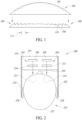
- Figure 1 shows a Fresnel lens 100 which may be conventionally used as an optical system for a HMD.
- the Fresnel lens 100 may include a periodic refractive structure of concentric prisms. The surfaces of each of these prisms are designed to refract light by collapsing an aspheric surface 102 of a corresponding conventional lens 104 into nearly a plane.
- the reduction in bulk lens thickness may be considered to be substantially equal to the volume bounded by the original aspheric surface 102 and the new lens surface defined by the surface of the prisms.
- this bulk reduction allows Fresnel lenses to be substantially thinner and lighter than their conventional counterparts, which is advantageous for HMD systems where reduced size and weight are important.
- the refractive surfaces 106 of the prisms which make up the Fresnel surface may be referred to as grooves 108 and drafts 110.
- the grooves 108 and drafts 110 may be collectively referred to herein as "Fresnel features," “Fresnel cuts,” or “microfeatures,” and the overall shape and dimensions of the grooves and drafts may be referred to as a Fresnel pattern.
- the grooves 108 are the actual surfaces which are used to approximate the continuous curvature of the aspheric surface 102 of the conventional lens 104, while the drafts 110 are the discontinuities between the grooves that are required to return the curvature of the lens back to a plane (or curved surface, as discussed below).
- the Fresnel lens may a pitch of 500 ⁇ m.
- the pitch for a Fresnel surface may be constant or variable across the lateral surface of a Fresnel lens.
- Fresnel surfaces are provided on curved surfaces (e.g., concave surfaces, convex surfaces) which, as discussed below, allows for unique and advantageous aberration control.
- FIG. 2 is a simplified top plan view of an HMD system 200 which includes a pair of near-to-eye display systems 202 and 204.
- the near-to-eye display systems 202 and 204 include displays 206 and 208, respectively (e.g., OLED micro display), and respective optical systems 210 and 212.
- the display systems 202 and 204 may be mounted to frame 214 which includes a front portion 216, a left temple 218 and right temple 220.
- the two display systems 202 and 204 may be secured to the frame 214 in an eye glasses arrangement which can be worn on the head 222 of a user 224.
- the left temple 218 and right temple 220 may rest over the user's ears 226 and 228, respectively, while a nose assembly (not shown) may rest over the user's nose 230.
- the frame 214 may be shaped and sized to position each of the two optical systems 210 and 212 in front of one of the user's eyes 232 and 234, respectively. Although the frame 214 is shown in a simplified manner similar to eyeglasses for explanatory purposes, it should be appreciated that in practice more sophisticated structures (e.g., goggles, integrated headband, helmet, straps) may be used to support and position the displays systems 202 and 204 on the head 222 of user 224.
- more sophisticated structures e.g., goggles, integrated headband, helmet, straps
- the HMD system 200 of Figure 2 is capable of presenting a virtual reality to the user 224.
- Each of the displays 206 and 208 may generate light which is transmitted through and focused by the respective optical systems 210 and 212 onto the eyes 232 and 234, respectively, of the user 224.
- the light is seen by the user 224 as images and/or video.
- the distance between each of the optical systems 210 and 212 and the user's eyes 232 and 234 may be relatively short (e.g., less than 30 mm, less than 20 mm), which advantageously causes the HMD system 200 to appear lighter to the user since the weight of the optical systems and the display systems are relatively close to the user's face.
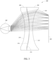
- Figure 3 shows a left-side sectional elevational view of an optical system 300 (e.g ., optical system 210 or optical system 212 of Figure 2 ) and a display 302 of the head mounted display system 200 of Figure 2 which includes a double Fresnel two element design.
- the display 302 may be a silicon-based micro display (e.g., OLED micro display), for example.
- the optical system 300 includes a first hybrid Fresnel lens element 304 which is positioned relatively proximate to the display 302, and a second hybrid Fresnel lens element 306 which is positioned relatively distal (relative to the first lens element 304) to the display and at least substantially adjacent the first lens element.
- the positions of the optical system 300 and the display 302 are shown relative to an eye 308 (e.g., left eye or right eye) of a user wearing the HMD system 200 (see Figure 2 ). As shown, the distance between the optical system 300 and the user's eye 308 may be relatively short (e.g., less than 25 mm, less than 20 mm). Light paths 310 between the display 302 and the user's eye 308 for light emitted by pixels of the display are also shown in Figure 3 .
- the first lens element 304 includes a first surface 312 facing toward the micro display 302 and a second surface 314 facing away from the micro display.
- the first surface 312 is a Fresnel surface which is concave and has Fresnel features (e.g. , grooves, drafts) thereon.
- the positive power of a Fresnel surface is "collapsed" onto a negative or concave element, which causes positive and negative aberrations to cancel each other.
- the Fresnel features are not shown in Figure 3 for the sake of simplicity.
- the second surface 314 may be a smooth concave surface having a profile which is spherical, aspherical, conical, etc.
- the second lens element 306 has a third surface 316 facing toward the micro display 302 and a fourth surface 318 facing away from the micro display ( i.e ., facing toward the user's eye 308).
- the third surface 316 is a Fresnel surface which is convex and has Fresnel features ( e.g ., grooves, drafts) thereon.
- the fourth surface 318 may be a smooth concave surface having a profile which is spherical, aspherical, conical, etc.
- Fresnel surfaces and smooth surfaces may be implemented.
- the surfaces 314 and 316 are Fresnel surfaces and the surfaces 312 and 318 are smooth surfaces.
- Such implementations may be advantageous by providing two Fresnel surfaces with opposing high-to-low and low-to-high index of refraction transitions.
- the low-to-high index of refraction transition between the air gap between the lens elements 304 and 306, which has a relatively lower index of refraction, and the surface 316 of the lens element 306, may function to cancel or reduce aberrations introduced by the high-to-low index of refraction transition between the surface 314 of the lens element 304 and the air gap.
- any combination of at least two of the surfaces 312, 314, 316 and 318 may be Fresnel surfaces, and the non-Fresnel lenses (if any) may be smooth surfaces.
- any of the Fresnel surfaces may be defined by a single Fresnel pattern or by multiple Fresnel patterns ( e.g ., two Fresnel patterns, four Fresnel patterns).
- one or more of the Fresnel surfaces may be defined by a first Fresnel pattern having a first associated focal length for relatively small fields of view (FOV) angles (e.g ., 0-50 degrees) and defined by a second Fresnel pattern having a second associated focal length for relatively large FOV angles (e.g ., 50-110 degrees).
- FOV fields of view
- two different Fresnel patterns or equations associated with first and second regions or zones of a Fresnel surface may be multiplexed, multiplied, or otherwise "blended" to provide a smooth transition in a third zone which is disposed between the first and second zones, which reduces aberrations at the edges of the first and second zones.
- the optical system 300 of Figure 3 allows four surfaces, i.e ., surfaces 312, 314, 316, and 318 to behave similar to six surfaces because in at least some implementations at least two of the surfaces (e.g ., surfaces 312 and 316, surfaces 314 and 316) provide Fresnel features as well as curved surface features (e.g., convex concave), which provides unique and advantageous aberration control.
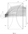
- Figure 4 shows a left-side sectional elevational view of an optical system 400 not according to the invention, which may be used in an HMD system, such as the HMD system 200 of Figure 2 .
- the optical system 400 provides a double Fresnel single element design.
- the optical system 400 includes a single hybrid Fresnel lens element 402 which is positioned proximate to the display 302 between the user's eye 308 and the display.
- the distance between the lens element 402 and the user's eye 308 may be relatively short ( e.g ., less than 25 mm, less than 20 mm).
- Light paths 310 between the display 302 and the user's eye 308 for light emitted by pixels of the display are also shown in Figure 4 .
- the lens element 402 includes a first surface 404 facing toward the micro display 302 and a second surface 406 facing away from the micro display.
- the first surface 404 is a Fresnel surface which is concave and has Fresnel features ( e.g ., grooves, drafts) thereon.
- the second surface 406 is also a Fresnel surface which is concave and has Fresnel features thereon.
- the Fresnel features are not shown for the sake of simplicity.
- the second surface 406 may have a larger radius of curvature than the first surface 404 such that no total internal reflection (TIR) condition occurs at the second surface.
- TIR total internal reflection
- the Fresnel surfaces 404 and 406 of the lens element 402 may each be defined by a single Fresnel pattern or by multiple Fresnel patterns.
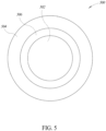
- FIG 5 is a top plan view of a Fresnel surface 500 of a lens element of an optical system of an HMD system, such as the HMD system 200 of Figure 2 .
- the Fresnel surface 500 may be representative of any of the Fresnel surfaces discussed above.
- the Fresnel surface 500 has a first or central zone 502 which has a profile defined by a first Fresnel pattern or equation.
- the Fresnel surface 500 also has a second or peripheral zone 504 which has a profile defined by a second Fresnel pattern or equation different from the first Fresnel pattern or equation.
- a third or transition zone 506 may be provided which has a profile that provides a smooth transition between the central zone 502 and the peripheral zone 504.
- the two Fresnel patterns or equations for the first and second zones may be multiplexed, multiplied, or otherwise blended to provide a transition equation or function which defines the profile of the Fresnel surface in the third or transition zone 506 which smoothly couples the first and second zones together without a discontinuity. Any suitable method may be used to generate a smooth profile transition between the central zone 502 and the peripheral zone 504.
- the Fresnel surface 500 may be defined by more than two ( e.g ., three, six, nine) Fresnel patterns or equations. In such instances, the techniques discussed herein may be used to provide a smooth transition between any or all adjacent zones of a Fresnel surface, which advantageously reduce aberrations at the edges of such zones.
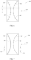
- Figure 6 shows a simplified left-side sectional elevational view of a double Fresnel lens element 600 which includes a first Fresnel surface 602 and a second Fresnel surface 604.
- the features of the lens element 600 may be implemented in any of the lens elements discussed above.
- hash marks 606 are shown to indicate boundaries between adjacent grooves on the first Fresnel surface 602
- hash marks 608 are shown to indicate boundaries between adjacent grooves on the second Fresnel surface 604.
- the distance between adjacent hash marks on a Fresnel surface represents the pitch for the Fresnel surface.
- An arrow 610 shows an optical axis for light emitted by a display ( e.g ., display 302 of Figures 3 and 4 ) toward the lens element 600.
- the Fresnel features of the first Fresnel surface 602 are offset by an offset distance D from Fresnel features of the second Fresnel surface 604.
- the offset distance D may be any suitable value (e.g ., 1/3 pitch, 1/2 pitch, 2/3 pitch, 3/2 pitch, 5/2 pitch). That is, the power of the surfaces 602 and 604 may be the same, but the respective pitches of the Fresnel patterns on each surface may be radially offset ( e.g ., shifted) relative to each other with respect to the central optical axis 610.
- the Fresnel features of the first Fresnel surface 602 may be radially aligned with the Fresnel features of the second Fresnel surface 604 rather than being offset therefrom.
- Figure 7 shows a simplified left-side sectional elevational view of a double Fresnel lens element 700 which includes a first Fresnel surface 702 and a second Fresnel surface 704.
- the features of the lens element 700 may be implemented in any of the lens elements discussed above.
- hash marks 706 are shown to indicate boundaries between adjacent grooves on the first Fresnel surface 702
- hash marks 708 are shown to indicate boundaries between adjacent grooves on the second Fresnel surface 704.
- the distance between adjacent hash marks on a Fresnel surface represents the pitch for the Fresnel surface.
- An arrow 710 shows an optical axis for light emitted by a display ( e.g ., the display 302 of Figure 3 ) toward the lens element 700.
- the pitch 712 of the Fresnel features of the first Fresnel surface 702 is different from the pitch 714 of the Fresnel features of the second Fresnel surface 704.
- the first Fresnel surface 702 may have Fresnel features having a pitch value 712 of 500 ⁇ m
- the second Fresnel surface 704 may have Fresnel features having a pitch value 714 of 200 ⁇ m, 550 ⁇ m, 800 ⁇ m, 1000 ⁇ m, etc.
- the pitch of the Fresnel features of the first Fresnel surface 702 may be the same as the pitch of the Fresnel features of the second Fresnel surface 704 rather than being different therefrom.
- the pitch of a Fresnel surface may be constant or variable across the radius of the Fresnel surface. In some implementations where the respective pitches of the Fresnel surfaces 702 and 704 are variable across the radius of the Fresnel surfaces, the pitch of the Fresnel surface 702 at a particular radius may be different from the pitch of the Fresnel surface 704 at the same radius.
- illustrated configurations may provide more or less functionality than is described, such as when other illustrated configurations instead lack or include such functionality respectively, or when the amount of functionality that is provided is altered.
- operations may be illustrated as being performed in a particular manner and/or in a particular order, those skilled in the art will appreciate that in other embodiments the operations may be performed in other orders and in other manners, within the scope of the claims.
Description
- The present disclosure generally relates to optical systems for displays, such as micro displays of head-mounted display systems.
- One current generation of virtual reality ("VR") experiences is created using head-mounted displays ("HMDs"), which can be tethered to a stationary computer (such as a personal computer ("PC"), laptop, or game console), combined and/or integrated with a smart phone and/or its associated display, or self-contained. Generally, HMDs are display devices, worn on the head of a user, which have a small display device in front of one (monocular HMD) or each eye (binocular HMD). The display units are typically miniaturized and may include CRT, LCD, Liquid crystal on silicon (LCos), or OLED technologies, for example. A binocular HMD has the potential to display a different image to each eye. This capability is used to display stereoscopic images.
- Demand for displays with heightened performance is increasing, including with the growth of smart phones and high-definition televisions, as well as other electronic devices. The growing popularity of virtual reality and augmented reality systems, particularly those using head mounted displays, has further increased such demand. Virtual reality systems typically envelop a wearer's eyes completely and substitute a "virtual" reality for the actual view (or actual reality) in front of the wearer, while augmented reality systems typically provide a semi-transparent or transparent overlay of one or more screens in front of a wearer's eyes such that actual view is augmented with additional information.
- However, such head mounted displays, with reduced distance between a viewer's eye and the display and often with a fully obscured field of view, have increased the performance requirements of displays in ways that traditional displays cannot satisfy, let alone to do so at cost-effective levels. Micro displays, such as OLED micro displays, are much smaller than traditional displays but involve additional challenges. For instance, micro displays require very short focal length lenses. Further, because the eye pupil size of a user is fixed, the F/# of a lens of an HMD which uses a micro display is decreased, which tends to increase the aberrations of a particular lens system. Moreover, micro displays have small pixels. This increase the spatial resolution of the HMD optic further increases the challenge to design and manufacture the lens for such an HMD.
-
US2012/0120498 describes a head mounted display apparatus employing one or more Fresnel lenses. - An optical system for use with a micro display in accordance with claim 1 is provided. Advantageous features are in the dependent claims.
- In the drawings, identical reference numbers identify similar elements or acts. The sizes and relative positions of elements in the drawings are not necessarily drawn to scale. For example, the shapes of various elements and angles are not necessarily drawn to scale, and some of these elements may be arbitrarily enlarged and positioned to improve drawing legibility. Further, the particular shapes of the elements as drawn, are not necessarily intended to convey any information regarding the actual shape of the particular elements, and may have been solely selected for ease of recognition in the drawings.
-
Figure 1 is an illustration of a Fresnel lens, according to one illustrated implementation. -
Figure 2 is a top plan view of a binocular head mounted display (HMD) system, according to one illustrated implementation. -
Figure 3 is a left-side sectional elevational view of an optical system of the HMD system ofFigure 2 which includes a double Fresnel two element design, according to one illustrated implementation. -
Figure 4 is a left-side sectional elevational view of an optical system of the HMD system ofFigure 2 which includes a double Fresnel single element design, according to one illustrated implementation. -
Figure 5 is a top plan view of a single element of an optical system of the HMD system ofFigure 2 , according to one illustrated implementation. -
Figure 6 is a left-side sectional elevational view of a double Fresnel lens element which includes a first surface which has Fresnel features which are offset from Fresnel features of an opposite second surface, according to one illustrated implementation. -
Figure 7 is a left-side sectional elevational view of a double Fresnel lens element which includes a first surface which has Fresnel features which have a first pitch value which is different from a second pitch value of Fresnel features of an opposite second surface, according to one illustrated implementation. - In the following description, certain specific details are set forth in order to provide a thorough understanding of various disclosed implementations. However, one skilled in the relevant art will recognize that implementations may be practiced without one or more of these specific details, or with other methods, components, materials, etc. In other instances, well-known structures associated with computer systems, server computers, and/or communications networks have not been shown or described in detail to avoid unnecessarily obscuring descriptions of the implementations.
- Unless the context requires otherwise, throughout the specification and claims that follow, the word "comprising" is synonymous with "including," and is inclusive or open-ended (i.e., does not exclude additional, unrecited elements or method acts).
- Reference throughout this specification to "one implementation" or "an implementation" means that a particular feature, structure or characteristic described in connection with the implementation is included in at least one implementation. Thus, the appearances of the phrases "in one implementation" or "in an implementation" in various places throughout this specification are not necessarily all referring to the same implementation. Furthermore, the particular features, structures, or characteristics may be combined in any suitable manner in one or more implementations.
- As used in this specification and the appended claims, the singular forms "a," "an," and "the" include plural referents unless the context clearly dictates otherwise. It should also be noted that the term "or" is generally employed in its sense including "and/or" unless the context clearly dictates otherwise.
- The headings and Abstract of the Disclosure provided herein are for convenience only and do not interpret the scope or meaning of the implementations.
- One or more implementations of the present disclosure are directed to optical systems which utilize stacked or double Fresnel lenses for use with display systems, such as silicon-based micro display systems (e.g., OLED micro displays) used with HMD systems. As used herein, "micro display systems" or "micro displays" refer to displays which have width and length dimensions which are each less than 35 mm (e.g., 12x12 mm, 20x20 mm, 30x30 mm, 18x30, 12x35 mm), and have a pixel size which is less than approximately 20 µm (e.g., 5 µm, 8 µm, 10 µm, 15 µm, 20 µm).
- One or more implementations discussed herein also provide optical systems which implement multiplexing or blending to provide a smooth profile transition and reduce aberrations between zones or fields (e.g., small FOV angles, large FOV angles) of a Fresnel surface which is defined by multiple different Fresnel patterns (e.g., two different Fresnel patterns). In at least some implementations, an optical system for a micro display is provided which utilizes double Fresnel lenses on curved surfaces to shorten the focal length while maintaining a good shape factor for moldability and aberration control. Such design allows for good aberration control while providing a large eyebox and low pupil swim.
- Generally, Fresnel lenses are a type of lens which provides a large aperture and a short focal length without requiring the mass and volume of material that would otherwise be required by a lens of conventional design.
Figure 1 shows a Fresnellens 100 which may be conventionally used as an optical system for a HMD. The Fresnellens 100 may include a periodic refractive structure of concentric prisms. The surfaces of each of these prisms are designed to refract light by collapsing anaspheric surface 102 of a correspondingconventional lens 104 into nearly a plane. Hence, the reduction in bulk lens thickness may be considered to be substantially equal to the volume bounded by the originalaspheric surface 102 and the new lens surface defined by the surface of the prisms. As noted above, this bulk reduction allows Fresnel lenses to be substantially thinner and lighter than their conventional counterparts, which is advantageous for HMD systems where reduced size and weight are important. - The
refractive surfaces 106 of the prisms which make up the Fresnel surface may be referred to asgrooves 108 anddrafts 110. Thegrooves 108 anddrafts 110 may be collectively referred to herein as "Fresnel features," "Fresnel cuts," or "microfeatures," and the overall shape and dimensions of the grooves and drafts may be referred to as a Fresnel pattern. Thegrooves 108 are the actual surfaces which are used to approximate the continuous curvature of theaspheric surface 102 of theconventional lens 104, while thedrafts 110 are the discontinuities between the grooves that are required to return the curvature of the lens back to a plane (or curved surface, as discussed below). The lateral distance between the peaks of adjacent grooves is referred to as thepitch 112. As an example, the Fresnel lens may a pitch of 500 µm. As discussed further below, the pitch for a Fresnel surface may be constant or variable across the lateral surface of a Fresnel lens. Further, although the Fresnel lens is shown inFigure 1 on a planar surface for explanatory purposes, in at least some of the implementations discussed herein Fresnel surfaces are provides on curved surfaces (e.g., concave surfaces, convex surfaces) which, as discussed below, allows for unique and advantageous aberration control. -
Figure 2 is a simplified top plan view of anHMD system 200 which includes a pair of near-to-eye display systems eye display systems displays optical systems display systems frame 214 which includes afront portion 216, aleft temple 218 andright temple 220. The twodisplay systems frame 214 in an eye glasses arrangement which can be worn on thehead 222 of auser 224. Theleft temple 218 andright temple 220 may rest over the user'sears nose 230. Theframe 214 may be shaped and sized to position each of the twooptical systems eyes frame 214 is shown in a simplified manner similar to eyeglasses for explanatory purposes, it should be appreciated that in practice more sophisticated structures (e.g., goggles, integrated headband, helmet, straps) may be used to support and position thedisplays systems head 222 ofuser 224. - The
HMD system 200 ofFigure 2 is capable of presenting a virtual reality to theuser 224. Each of thedisplays optical systems eyes user 224. The light is seen by theuser 224 as images and/or video. In some implementations, the distance between each of theoptical systems eyes HMD system 200 to appear lighter to the user since the weight of the optical systems and the display systems are relatively close to the user's face. -
Figure 3 shows a left-side sectional elevational view of an optical system 300 (e.g.,optical system 210 oroptical system 212 ofFigure 2 ) and adisplay 302 of the head mounteddisplay system 200 ofFigure 2 which includes a double Fresnel two element design. Thedisplay 302 may be a silicon-based micro display (e.g., OLED micro display), for example. In this implementation, theoptical system 300 includes a first hybridFresnel lens element 304 which is positioned relatively proximate to thedisplay 302, and a second hybridFresnel lens element 306 which is positioned relatively distal (relative to the first lens element 304) to the display and at least substantially adjacent the first lens element. The positions of theoptical system 300 and thedisplay 302 are shown relative to an eye 308 (e.g., left eye or right eye) of a user wearing the HMD system 200 (seeFigure 2 ). As shown, the distance between theoptical system 300 and the user'seye 308 may be relatively short (e.g., less than 25 mm, less than 20 mm).Light paths 310 between thedisplay 302 and the user'seye 308 for light emitted by pixels of the display are also shown inFigure 3 . - The
first lens element 304 includes afirst surface 312 facing toward themicro display 302 and asecond surface 314 facing away from the micro display. In at least some implementations, thefirst surface 312 is a Fresnel surface which is concave and has Fresnel features (e.g., grooves, drafts) thereon. Thus, the positive power of a Fresnel surface is "collapsed" onto a negative or concave element, which causes positive and negative aberrations to cancel each other. The Fresnel features are not shown inFigure 3 for the sake of simplicity. In at least some implementations, thesecond surface 314 may be a smooth concave surface having a profile which is spherical, aspherical, conical, etc. - The
second lens element 306 has athird surface 316 facing toward themicro display 302 and afourth surface 318 facing away from the micro display (i.e., facing toward the user's eye 308). In at least some implementations, thethird surface 316 is a Fresnel surface which is convex and has Fresnel features (e.g., grooves, drafts) thereon. In at least some implementations, thefourth surface 318 may be a smooth concave surface having a profile which is spherical, aspherical, conical, etc. - Other combinations of Fresnel surfaces and smooth surfaces may be implemented. For example, in at least some implementations the
surfaces surfaces lens elements surface 316 of thelens element 306, may function to cancel or reduce aberrations introduced by the high-to-low index of refraction transition between thesurface 314 of thelens element 304 and the air gap. - More generally, any combination of at least two of the
surfaces - Any of the Fresnel surfaces may be defined by a single Fresnel pattern or by multiple Fresnel patterns (e.g., two Fresnel patterns, four Fresnel patterns). As an example, one or more of the Fresnel surfaces may be defined by a first Fresnel pattern having a first associated focal length for relatively small fields of view (FOV) angles (e.g., 0-50 degrees) and defined by a second Fresnel pattern having a second associated focal length for relatively large FOV angles (e.g., 50-110 degrees). As discussed further below with reference to
Figure 5 , in some implementations, two different Fresnel patterns or equations associated with first and second regions or zones of a Fresnel surface may be multiplexed, multiplied, or otherwise "blended" to provide a smooth transition in a third zone which is disposed between the first and second zones, which reduces aberrations at the edges of the first and second zones. - Advantageously, the
optical system 300 ofFigure 3 allows four surfaces, i.e., surfaces 312, 314, 316, and 318 to behave similar to six surfaces because in at least some implementations at least two of the surfaces (e.g., surfaces 312 and 316,surfaces 314 and 316) provide Fresnel features as well as curved surface features (e.g., convex concave), which provides unique and advantageous aberration control. -
Figure 4 shows a left-side sectional elevational view of anoptical system 400 not according to the invention, which may be used in an HMD system, such as theHMD system 200 ofFigure 2 . Theoptical system 400 provides a double Fresnel single element design. In this implementation, theoptical system 400 includes a single hybridFresnel lens element 402 which is positioned proximate to thedisplay 302 between the user'seye 308 and the display. As shown, the distance between thelens element 402 and the user'seye 308 may be relatively short (e.g., less than 25 mm, less than 20 mm).Light paths 310 between thedisplay 302 and the user'seye 308 for light emitted by pixels of the display are also shown inFigure 4 . - The
lens element 402 includes afirst surface 404 facing toward themicro display 302 and asecond surface 406 facing away from the micro display. Thefirst surface 404 is a Fresnel surface which is concave and has Fresnel features (e.g., grooves, drafts) thereon. Thesecond surface 406 is also a Fresnel surface which is concave and has Fresnel features thereon. The Fresnel features are not shown for the sake of simplicity. In some implementations, thesecond surface 406 may have a larger radius of curvature than thefirst surface 404 such that no total internal reflection (TIR) condition occurs at the second surface. Like the Fresnel surfaces 312 and 316 ofFigure 3 discussed above, the Fresnel surfaces 404 and 406 of thelens element 402 may each be defined by a single Fresnel pattern or by multiple Fresnel patterns. -
Figure 5 is a top plan view of aFresnel surface 500 of a lens element of an optical system of an HMD system, such as theHMD system 200 ofFigure 2 . TheFresnel surface 500 may be representative of any of the Fresnel surfaces discussed above. As shown, theFresnel surface 500 has a first orcentral zone 502 which has a profile defined by a first Fresnel pattern or equation. TheFresnel surface 500 also has a second orperipheral zone 504 which has a profile defined by a second Fresnel pattern or equation different from the first Fresnel pattern or equation. In this example, a third ortransition zone 506 may be provided which has a profile that provides a smooth transition between thecentral zone 502 and theperipheral zone 504. For example, the two Fresnel patterns or equations for the first and second zones may be multiplexed, multiplied, or otherwise blended to provide a transition equation or function which defines the profile of the Fresnel surface in the third ortransition zone 506 which smoothly couples the first and second zones together without a discontinuity. Any suitable method may be used to generate a smooth profile transition between thecentral zone 502 and theperipheral zone 504. Additionally, in some implementations, theFresnel surface 500 may be defined by more than two (e.g., three, six, nine) Fresnel patterns or equations. In such instances, the techniques discussed herein may be used to provide a smooth transition between any or all adjacent zones of a Fresnel surface, which advantageously reduce aberrations at the edges of such zones. -
Figure 6 shows a simplified left-side sectional elevational view of a doubleFresnel lens element 600 which includes afirst Fresnel surface 602 and asecond Fresnel surface 604. The features of thelens element 600 may be implemented in any of the lens elements discussed above. InFigure 6 , hash marks 606 are shown to indicate boundaries between adjacent grooves on thefirst Fresnel surface 602, and hash marks 608 are shown to indicate boundaries between adjacent grooves on thesecond Fresnel surface 604. The distance between adjacent hash marks on a Fresnel surface represents the pitch for the Fresnel surface. Anarrow 610 shows an optical axis for light emitted by a display (e.g., display 302 ofFigures 3 and4 ) toward thelens element 600. As shown, the Fresnel features of thefirst Fresnel surface 602 are offset by an offset distance D from Fresnel features of thesecond Fresnel surface 604. The offset distance D may be any suitable value (e.g., 1/3 pitch, 1/2 pitch, 2/3 pitch, 3/2 pitch, 5/2 pitch). That is, the power of thesurfaces optical axis 610. In other implementations, the Fresnel features of thefirst Fresnel surface 602 may be radially aligned with the Fresnel features of thesecond Fresnel surface 604 rather than being offset therefrom. -
Figure 7 shows a simplified left-side sectional elevational view of a doubleFresnel lens element 700 which includes afirst Fresnel surface 702 and asecond Fresnel surface 704. The features of thelens element 700 may be implemented in any of the lens elements discussed above. InFigure 7 , hash marks 706 are shown to indicate boundaries between adjacent grooves on thefirst Fresnel surface 702, and hash marks 708 are shown to indicate boundaries between adjacent grooves on thesecond Fresnel surface 704. The distance between adjacent hash marks on a Fresnel surface represents the pitch for the Fresnel surface. Anarrow 710 shows an optical axis for light emitted by a display (e.g., thedisplay 302 ofFigure 3 ) toward thelens element 700. As shown inFigure 7 , thepitch 712 of the Fresnel features of thefirst Fresnel surface 702 is different from thepitch 714 of the Fresnel features of thesecond Fresnel surface 704. For example, thefirst Fresnel surface 702 may have Fresnel features having apitch value 712 of 500 µm, and thesecond Fresnel surface 704 may have Fresnel features having apitch value 714 of 200 µm, 550 µm, 800 µm, 1000 µm, etc. In other implementations, the pitch of the Fresnel features of thefirst Fresnel surface 702 may be the same as the pitch of the Fresnel features of thesecond Fresnel surface 704 rather than being different therefrom. Additionally, as noted above, the pitch of a Fresnel surface may be constant or variable across the radius of the Fresnel surface. In some implementations where the respective pitches of the Fresnel surfaces 702 and 704 are variable across the radius of the Fresnel surfaces, the pitch of theFresnel surface 702 at a particular radius may be different from the pitch of theFresnel surface 704 at the same radius. - It will be appreciated that in some embodiments the functionality discussed above may be provided in alternative ways, within the scope of the claims. Similarly, in some embodiments illustrated configurations may provide more or less functionality than is described, such as when other illustrated configurations instead lack or include such functionality respectively, or when the amount of functionality that is provided is altered. In addition, while various operations may be illustrated as being performed in a particular manner and/or in a particular order, those skilled in the art will appreciate that in other embodiments the operations may be performed in other orders and in other manners, within the scope of the claims.
Claims (14)
- An optical system (300) for use with a micro display (302) to focus light from the micro display (302) onto an eye (308) of a user, the optical system comprising:a first lens element (304) disposed relatively proximate to the micro display (302), the first lens element comprisinga first surface (312) facing toward the micro display (302) anda second surface (314) facing away from the micro display (302) toward the eye (308) of the user,the first surface (312) comprising a concave shape that provides negative power andthe second surface (314) comprising a concave shape that provides negative power,at least one of the first surface (312) and the second surface (314) having Fresnel features thereon that include grooves that approximate the continuous curvature of a lens that provides positive power,
wherein, for each of the first surface (312) and the second surface (314) that includes Fresnel features thereon, the Fresnel features on the surface and the concave shape of the surface cause positive aberrations and negative aberrations to cancel each other;a second lens element (306) disposed relatively distal to the micro display (302), the second lens element (306) comprisinga third surface (316) facing toward the micro display (302) anda fourth surface (318) facing away from the micro display (302) toward the eye (308) of the user,the third surface (316) comprising a convex shape andthe fourth surface (318) comprising a concave shape,at least one of the third surface (316) and the fourth surface (318) having Fresnel features thereon;wherein each of at least one of the first surface (312), second surface (314), third surface (316), and fourth surface (318) includes a first zone defined by a first Fresnel pattern and a second zone defined by a second Fresnel pattern, and
wherein the first Fresnel pattern has a first focal length associated therewith to provide a first field of view angle, and the second Fresnel pattern has a second focal length associated therewith to provide a second field of view angle that is larger than the first field of view angle. - The optical system of claim 1 wherein:at least the first surface and the third surface have Fresnel features thereon; orat least the second surface and the third surface have Fresnel features thereon; orat least the first surface and the fourth surface have Fresnel features thereon; orat least the second surface and the fourth surface have Fresnel features thereon; orat least three of the first surface, second surface, third surface and fourth surface have Fresnel features thereon.
- The optical system of claim 1 wherein at least one of the first surface, second surface, third surface and fourth surface comprises Fresnel features defined by multiple Fresnel patterns, or defined by a single Fresnel pattern.
- The optical system of claim 1 wherein at least one of the first surface, second surface, third surface and fourth surface includes a first zone defined by a first Fresnel pattern and a second zone defined by a second Fresnel pattern.
- The optical system of claim 4 wherein the at least one of the first surface, second surface, third surface, and fourth surface includes a third zone disposed between the first zone and the second zone, the third zone being defined by a third Fresnel pattern which provides a transition region in the third zone between the first zone and the second zone.
- The optical system of claim 5 wherein the third Fresnel pattern is defined by a first function representative of the first Fresnel pattern at least one of multiplexed with or multiplied by a second function representative of the second Fresnel pattern.
- The optical system of claim 1 wherein each of the at least one of the first surface, second surface, third surface, and fourth surface includes a third zone disposed between the first zone and the second zone, the third zone defined by a third Fresnel pattern which provides a smooth transition in the third zone between the first zone and the second zone.
- The optical system of claim 7 wherein a third function representative of the third Fresnel pattern is defined by a first function representative of the first Fresnel pattern at least one of multiplexed with or multiplied by a second function representative of the second Fresnel pattern.
- The optical system of claim 8 wherein the first zone comprises a central zone and the second zone comprises a peripheral zone which surrounds the first zone.
- The optical system of claim 1 wherein the first and second lens elements have a combined focal length which is less than 25 mm, or wherein the first and second lens elements provide a field of view which is at least 85 degrees.
- The optical system of claim 1 wherein at least one of the first surface, second surface, third surface, and fourth surface comprise Fresnel features having a first pitch value, and at least one of the first surface, second surface, third surface, and fourth surface comprises Fresnel features having a second pitch value, the first pitch value different from the second pitch value.
- The optical system of claim 1 wherein the Fresnel features of at least one of the first surface, second surface, third surface, and fourth surface are radially aligned along a central optical axis with the Fresnel features of at least one other of the first surface, second surface, third surface and fourth surface.
- The optical system of claim 1 wherein the Fresnel features of at least one of the first surface, second surface, third surface, and fourth surface are radially offset along a central optical axis with the Fresnel features of at least one other of the first surface, second surface, third surface and fourth surface.
- The optical system of claim 1 wherein the first lens element and the second lens element are separated by an air gap, the air gap having an index of refraction which is less than the index of refraction of the first lens element and the less than the index of refraction of the second lens element.
Applications Claiming Priority (2)
| Application Number | Priority Date | Filing Date | Title |
|---|---|---|---|
| US201662395513P | 2016-09-16 | 2016-09-16 | |
| PCT/US2017/051579 WO2018053141A1 (en) | 2016-09-16 | 2017-09-14 | Optical system for head-mounted display system |
Publications (3)
| Publication Number | Publication Date |
|---|---|
| EP3513243A1 EP3513243A1 (en) | 2019-07-24 |
| EP3513243A4 EP3513243A4 (en) | 2020-04-29 |
| EP3513243B1 true EP3513243B1 (en) | 2024-04-03 |
Family
ID=61619702
Family Applications (1)
| Application Number | Title | Priority Date | Filing Date |
|---|---|---|---|
| EP17851535.9A Active EP3513243B1 (en) | 2016-09-16 | 2017-09-14 | Optical system for head-mounted display system |
Country Status (6)
| Country | Link |
|---|---|
| US (1) | US10890694B2 (en) |
| EP (1) | EP3513243B1 (en) |
| JP (1) | JP7120529B2 (en) |
| KR (1) | KR102489882B1 (en) |
| CN (1) | CN109791290B (en) |
| WO (1) | WO2018053141A1 (en) |
Families Citing this family (14)
| Publication number | Priority date | Publication date | Assignee | Title |
|---|---|---|---|---|
| JP7086581B2 (en) * | 2016-12-21 | 2022-06-20 | キヤノン株式会社 | Observation optical system and observation equipment having it |
| US11181731B1 (en) * | 2017-01-02 | 2021-11-23 | Kopin Corporation | Wide field of view (WFOV) optical system and method |
| US11054646B1 (en) * | 2017-05-11 | 2021-07-06 | Apple Inc. | Head-mounted display device with Fresnel lenses |
| WO2019163415A1 (en) * | 2018-02-22 | 2019-08-29 | 株式会社ニコン | Ocular optical system and head-mounted display |
| CN110376735B (en) * | 2018-04-12 | 2021-10-22 | 京东方科技集团股份有限公司 | VR lens structure and display system |
| WO2019238856A1 (en) * | 2018-06-15 | 2019-12-19 | Continental Automotive Gmbh | Apparatus for generating a virtual image, having micro-light sources |
| WO2020021916A1 (en) * | 2018-07-24 | 2020-01-30 | 株式会社ニコン | Ocular optical system and head mounted display |
| RU2685061C1 (en) * | 2018-10-15 | 2019-04-16 | Олег Леонидович Головков | Fresnel lens for virtual helmet (versions) |
| CN111699428A (en) * | 2019-06-26 | 2020-09-22 | 深圳市大疆创新科技有限公司 | Optical lens group, imaging system and wearable display device |
| EP3929649A4 (en) * | 2019-11-26 | 2022-04-06 | Shenzhen Nade Optical Co., Ltd. | Large-field-of-view high-image-quality eyepiece optical system and device |
| TWI751869B (en) * | 2020-12-30 | 2022-01-01 | 廣達電腦股份有限公司 | Computation apparatus and method of detecting defects for near-eye display |
| TW202235956A (en) | 2021-03-05 | 2022-09-16 | 大立光電股份有限公司 | Head-mounted device |
| TWM621801U (en) | 2021-08-16 | 2022-01-01 | 大立光電股份有限公司 | Head-mounted device |
| CN114296234A (en) * | 2021-12-10 | 2022-04-08 | 华为技术有限公司 | Near-to-eye display device and head-mounted equipment |
Citations (2)
| Publication number | Priority date | Publication date | Assignee | Title |
|---|---|---|---|---|
| WO2001035154A1 (en) * | 1999-11-11 | 2001-05-17 | 4D-Vision Gmbh | Method and device for effecting a three-dimensional display |
| US6364483B1 (en) * | 2000-02-22 | 2002-04-02 | Holo Or Ltd. | Simultaneous multifocal contact lens and method of utilizing same for treating visual disorders |
Family Cites Families (22)
| Publication number | Priority date | Publication date | Assignee | Title |
|---|---|---|---|---|
| US4075483A (en) | 1976-07-12 | 1978-02-21 | Raytheon Company | Multiple masking imaging system |
| JPH1138330A (en) * | 1997-05-21 | 1999-02-12 | Asahi Optical Co Ltd | Eyepiece |
| US6269145B1 (en) | 1999-05-07 | 2001-07-31 | Adelphi Technology, Inc. | Compound refractive lens for x-rays |
| US7777949B2 (en) * | 2002-08-16 | 2010-08-17 | Seiko Epson Corporation | Laminate screen for a display device |
| US7187505B2 (en) | 2002-10-07 | 2007-03-06 | Fresnel Technologies, Inc. | Imaging lens for infrared cameras |
| US7144111B1 (en) | 2002-10-18 | 2006-12-05 | Ross Iii Denwood F | Ophthalmoscopy lens system |
| JP2005037561A (en) * | 2003-07-17 | 2005-02-10 | Ricoh Co Ltd | Optical scanner and image forming apparatus provided with the same |
| US20070216851A1 (en) * | 2006-03-01 | 2007-09-20 | Citizen Watch Co., Ltd. | Liquid crystal lens and imaging lens device |
| JP5037149B2 (en) * | 2006-03-01 | 2012-09-26 | シチズンホールディングス株式会社 | Imaging lens device |
| US8212859B2 (en) * | 2006-10-13 | 2012-07-03 | Apple Inc. | Peripheral treatment for head-mounted displays |
| KR100910393B1 (en) * | 2007-08-31 | 2009-08-04 | (주)쓰리디아이에스 | The real image display device with wide viewing angle |
| TWI476452B (en) * | 2007-12-14 | 2015-03-11 | 尼康股份有限公司 | Diffractive optical systems and optical machines |
| CA2712059A1 (en) * | 2008-01-22 | 2009-07-30 | The Arizona Board Of Regents On Behalf Of The University Of Arizona | Head-mounted projection display using reflective microdisplays |
| JP2011191715A (en) | 2010-03-17 | 2011-09-29 | Toshiba Corp | Optical element, display device, display method, and moving body |
| US10359545B2 (en) | 2010-10-21 | 2019-07-23 | Lockheed Martin Corporation | Fresnel lens with reduced draft facet visibility |
| US9632315B2 (en) * | 2010-10-21 | 2017-04-25 | Lockheed Martin Corporation | Head-mounted display apparatus employing one or more fresnel lenses |
| KR101916079B1 (en) * | 2010-12-28 | 2018-11-07 | 록히드 마틴 코포레이션 | Head-mounted display apparatus employing one or more fresnel lenses |
| JP5732939B2 (en) | 2011-03-16 | 2015-06-10 | セイコーエプソン株式会社 | prompter |
| WO2014041691A1 (en) * | 2012-09-14 | 2014-03-20 | パイオニア株式会社 | Optical element and heads-up display |
| KR20140115501A (en) | 2013-03-20 | 2014-10-01 | 삼성에스디아이 주식회사 | Power conversion device having battery heating function |
| US20160209556A1 (en) * | 2015-01-16 | 2016-07-21 | Valve Corporation | Low f/# lens |
| US10215890B2 (en) * | 2016-05-18 | 2019-02-26 | Google Llc | Optical field curvature control using multi-layer Fresnel lens in VR display |
-
2017
- 2017-09-14 JP JP2019514032A patent/JP7120529B2/en active Active
- 2017-09-14 WO PCT/US2017/051579 patent/WO2018053141A1/en unknown
- 2017-09-14 EP EP17851535.9A patent/EP3513243B1/en active Active
- 2017-09-14 KR KR1020197010897A patent/KR102489882B1/en active IP Right Grant
- 2017-09-14 CN CN201780056323.4A patent/CN109791290B/en active Active
- 2017-09-14 US US15/704,813 patent/US10890694B2/en active Active
Patent Citations (2)
| Publication number | Priority date | Publication date | Assignee | Title |
|---|---|---|---|---|
| WO2001035154A1 (en) * | 1999-11-11 | 2001-05-17 | 4D-Vision Gmbh | Method and device for effecting a three-dimensional display |
| US6364483B1 (en) * | 2000-02-22 | 2002-04-02 | Holo Or Ltd. | Simultaneous multifocal contact lens and method of utilizing same for treating visual disorders |
Also Published As
| Publication number | Publication date |
|---|---|
| US10890694B2 (en) | 2021-01-12 |
| WO2018053141A1 (en) | 2018-03-22 |
| EP3513243A4 (en) | 2020-04-29 |
| JP2019529995A (en) | 2019-10-17 |
| US20180081092A1 (en) | 2018-03-22 |
| KR102489882B1 (en) | 2023-01-18 |
| EP3513243A1 (en) | 2019-07-24 |
| CN109791290A (en) | 2019-05-21 |
| CN109791290B (en) | 2021-12-07 |
| JP7120529B2 (en) | 2022-08-17 |
| KR20190062445A (en) | 2019-06-05 |
Similar Documents
| Publication | Publication Date | Title |
|---|---|---|
| EP3513243B1 (en) | Optical system for head-mounted display system | |
| EP3320384B1 (en) | Adding prescriptive correction to eyepieces for see-through head wearable displays | |
| CN107533227B (en) | Effective thin curved eyepiece for see-through head mounted display | |
| EP3245552B1 (en) | Hybrid lens system for head wearable display | |
| US10754160B2 (en) | See-through curved eyepiece with patterned optical combiner | |
| EP3586182B1 (en) | Freeform head mounted display | |
| EP3134763B1 (en) | Compact architecture for near-to-eye display system | |
| US9366869B2 (en) | Thin curved eyepiece for see-through head wearable display | |
| US9915823B1 (en) | Lightguide optical combiner for head wearable display | |
| US11754836B2 (en) | Optical system for AR headsets, and method for design and manufacturing | |
| US11747525B1 (en) | Self-aligned lens assembly for head-mounted displays | |
| CN111033356B (en) | Eyepiece for a personal display and personal display comprising such an eyepiece | |
| GB2573799A (en) | Improvements in or relating to wearable optical devices |
Legal Events
| Date | Code | Title | Description |
|---|---|---|---|
| STAA | Information on the status of an ep patent application or granted ep patent |
Free format text: STATUS: THE INTERNATIONAL PUBLICATION HAS BEEN MADE |
|
| PUAI | Public reference made under article 153(3) epc to a published international application that has entered the european phase |
Free format text: ORIGINAL CODE: 0009012 |
|
| STAA | Information on the status of an ep patent application or granted ep patent |
Free format text: STATUS: REQUEST FOR EXAMINATION WAS MADE |
|
| 17P | Request for examination filed |
Effective date: 20190226 |
|
| AK | Designated contracting states |
Kind code of ref document: A1 Designated state(s): AL AT BE BG CH CY CZ DE DK EE ES FI FR GB GR HR HU IE IS IT LI LT LU LV MC MK MT NL NO PL PT RO RS SE SI SK SM TR |
|
| AX | Request for extension of the european patent |
Extension state: BA ME |
|
| DAV | Request for validation of the european patent (deleted) | ||
| DAX | Request for extension of the european patent (deleted) | ||
| A4 | Supplementary search report drawn up and despatched |
Effective date: 20200326 |
|
| RIC1 | Information provided on ipc code assigned before grant |
Ipc: G01B 17/06 20060101ALI20200321BHEP Ipc: G02B 3/08 20060101ALI20200321BHEP Ipc: G01S 7/48 20060101ALI20200321BHEP Ipc: G02B 25/00 20060101ALI20200321BHEP Ipc: B24B 51/00 20060101ALI20200321BHEP Ipc: G01B 11/27 20060101ALI20200321BHEP Ipc: G02B 27/01 20060101AFI20200321BHEP Ipc: B24B 1/00 20060101ALI20200321BHEP |
|
| STAA | Information on the status of an ep patent application or granted ep patent |
Free format text: STATUS: EXAMINATION IS IN PROGRESS |
|
| 17Q | First examination report despatched |
Effective date: 20220330 |
|
| REG | Reference to a national code |
Ref document number: 602017080680 Country of ref document: DE Ipc: G02B0005180000 Ref country code: DE Ref legal event code: R079 Free format text: PREVIOUS MAIN CLASS: G02B0027010000 |
|
| GRAP | Despatch of communication of intention to grant a patent |
Free format text: ORIGINAL CODE: EPIDOSNIGR1 |
|
| STAA | Information on the status of an ep patent application or granted ep patent |
Free format text: STATUS: GRANT OF PATENT IS INTENDED |
|
| RIC1 | Information provided on ipc code assigned before grant |
Ipc: G02B 27/01 20060101ALN20231010BHEP Ipc: G02B 25/00 20060101ALI20231010BHEP Ipc: G02B 3/08 20060101ALI20231010BHEP Ipc: G02B 27/42 20060101ALI20231010BHEP Ipc: G02B 5/18 20060101AFI20231010BHEP |
|
| INTG | Intention to grant announced |
Effective date: 20231103 |
|
| GRAS | Grant fee paid |
Free format text: ORIGINAL CODE: EPIDOSNIGR3 |
|
| GRAA | (expected) grant |
Free format text: ORIGINAL CODE: 0009210 |
|
| STAA | Information on the status of an ep patent application or granted ep patent |
Free format text: STATUS: THE PATENT HAS BEEN GRANTED |
|
| P01 | Opt-out of the competence of the unified patent court (upc) registered |
Effective date: 20240126 |
|
| AK | Designated contracting states |
Kind code of ref document: B1 Designated state(s): AL AT BE BG CH CY CZ DE DK EE ES FI FR GB GR HR HU IE IS IT LI LT LU LV MC MK MT NL NO PL PT RO RS SE SI SK SM TR |
|
| REG | Reference to a national code |
Ref country code: GB Ref legal event code: FG4D |
|
| REG | Reference to a national code |
Ref country code: CH Ref legal event code: EP |
|
| REG | Reference to a national code |
Ref country code: DE Ref legal event code: R096 Ref document number: 602017080680 Country of ref document: DE |