EP3513086B1 - Kupplungsanordnung und windturbine mit solch einer anordnung - Google Patents
Kupplungsanordnung und windturbine mit solch einer anordnung Download PDFInfo
- Publication number
- EP3513086B1 EP3513086B1 EP17754605.8A EP17754605A EP3513086B1 EP 3513086 B1 EP3513086 B1 EP 3513086B1 EP 17754605 A EP17754605 A EP 17754605A EP 3513086 B1 EP3513086 B1 EP 3513086B1
- Authority
- EP
- European Patent Office
- Prior art keywords
- coupling assembly
- coupling element
- coupling
- bolts
- shrink ring
- Prior art date
- Legal status (The legal status is an assumption and is not a legal conclusion. Google has not performed a legal analysis and makes no representation as to the accuracy of the status listed.)
- Active
Links
Images




Classifications
-
- F—MECHANICAL ENGINEERING; LIGHTING; HEATING; WEAPONS; BLASTING
- F16—ENGINEERING ELEMENTS AND UNITS; GENERAL MEASURES FOR PRODUCING AND MAINTAINING EFFECTIVE FUNCTIONING OF MACHINES OR INSTALLATIONS; THERMAL INSULATION IN GENERAL
- F16D—COUPLINGS FOR TRANSMITTING ROTATION; CLUTCHES; BRAKES
- F16D1/00—Couplings for rigidly connecting two coaxial shafts or other movable machine elements
- F16D1/06—Couplings for rigidly connecting two coaxial shafts or other movable machine elements for attachment of a member on a shaft or on a shaft-end
- F16D1/08—Couplings for rigidly connecting two coaxial shafts or other movable machine elements for attachment of a member on a shaft or on a shaft-end with clamping hub; with hub and longitudinal key
- F16D1/09—Couplings for rigidly connecting two coaxial shafts or other movable machine elements for attachment of a member on a shaft or on a shaft-end with clamping hub; with hub and longitudinal key with radial clamping due to axial loading of at least one pair of conical surfaces
- F16D1/093—Couplings for rigidly connecting two coaxial shafts or other movable machine elements for attachment of a member on a shaft or on a shaft-end with clamping hub; with hub and longitudinal key with radial clamping due to axial loading of at least one pair of conical surfaces using one or more elastic segmented conical rings forming at least one of the conical surfaces, the rings being expanded or contracted to effect clamping
- F16D1/095—Couplings for rigidly connecting two coaxial shafts or other movable machine elements for attachment of a member on a shaft or on a shaft-end with clamping hub; with hub and longitudinal key with radial clamping due to axial loading of at least one pair of conical surfaces using one or more elastic segmented conical rings forming at least one of the conical surfaces, the rings being expanded or contracted to effect clamping with clamping effected by ring contraction only
- F16D1/096—Couplings for rigidly connecting two coaxial shafts or other movable machine elements for attachment of a member on a shaft or on a shaft-end with clamping hub; with hub and longitudinal key with radial clamping due to axial loading of at least one pair of conical surfaces using one or more elastic segmented conical rings forming at least one of the conical surfaces, the rings being expanded or contracted to effect clamping with clamping effected by ring contraction only the ring or rings being located between the shaft and the hub
-
- F—MECHANICAL ENGINEERING; LIGHTING; HEATING; WEAPONS; BLASTING
- F16—ENGINEERING ELEMENTS AND UNITS; GENERAL MEASURES FOR PRODUCING AND MAINTAINING EFFECTIVE FUNCTIONING OF MACHINES OR INSTALLATIONS; THERMAL INSULATION IN GENERAL
- F16D—COUPLINGS FOR TRANSMITTING ROTATION; CLUTCHES; BRAKES
- F16D1/00—Couplings for rigidly connecting two coaxial shafts or other movable machine elements
- F16D1/02—Couplings for rigidly connecting two coaxial shafts or other movable machine elements for connecting two abutting shafts or the like
- F16D1/04—Couplings for rigidly connecting two coaxial shafts or other movable machine elements for connecting two abutting shafts or the like with clamping hub; with hub and longitudinal key
- F16D1/05—Couplings for rigidly connecting two coaxial shafts or other movable machine elements for connecting two abutting shafts or the like with clamping hub; with hub and longitudinal key with radial clamping due to axial loading of at least one pair of conical surfaces
-
- F—MECHANICAL ENGINEERING; LIGHTING; HEATING; WEAPONS; BLASTING
- F16—ENGINEERING ELEMENTS AND UNITS; GENERAL MEASURES FOR PRODUCING AND MAINTAINING EFFECTIVE FUNCTIONING OF MACHINES OR INSTALLATIONS; THERMAL INSULATION IN GENERAL
- F16D—COUPLINGS FOR TRANSMITTING ROTATION; CLUTCHES; BRAKES
- F16D1/00—Couplings for rigidly connecting two coaxial shafts or other movable machine elements
- F16D1/06—Couplings for rigidly connecting two coaxial shafts or other movable machine elements for attachment of a member on a shaft or on a shaft-end
- F16D1/08—Couplings for rigidly connecting two coaxial shafts or other movable machine elements for attachment of a member on a shaft or on a shaft-end with clamping hub; with hub and longitudinal key
- F16D1/09—Couplings for rigidly connecting two coaxial shafts or other movable machine elements for attachment of a member on a shaft or on a shaft-end with clamping hub; with hub and longitudinal key with radial clamping due to axial loading of at least one pair of conical surfaces
- F16D2001/0903—Couplings for rigidly connecting two coaxial shafts or other movable machine elements for attachment of a member on a shaft or on a shaft-end with clamping hub; with hub and longitudinal key with radial clamping due to axial loading of at least one pair of conical surfaces the clamped shaft being hollow
-
- F—MECHANICAL ENGINEERING; LIGHTING; HEATING; WEAPONS; BLASTING
- F16—ENGINEERING ELEMENTS AND UNITS; GENERAL MEASURES FOR PRODUCING AND MAINTAINING EFFECTIVE FUNCTIONING OF MACHINES OR INSTALLATIONS; THERMAL INSULATION IN GENERAL
- F16D—COUPLINGS FOR TRANSMITTING ROTATION; CLUTCHES; BRAKES
- F16D1/00—Couplings for rigidly connecting two coaxial shafts or other movable machine elements
- F16D1/06—Couplings for rigidly connecting two coaxial shafts or other movable machine elements for attachment of a member on a shaft or on a shaft-end
- F16D1/08—Couplings for rigidly connecting two coaxial shafts or other movable machine elements for attachment of a member on a shaft or on a shaft-end with clamping hub; with hub and longitudinal key
- F16D1/09—Couplings for rigidly connecting two coaxial shafts or other movable machine elements for attachment of a member on a shaft or on a shaft-end with clamping hub; with hub and longitudinal key with radial clamping due to axial loading of at least one pair of conical surfaces
- F16D1/093—Couplings for rigidly connecting two coaxial shafts or other movable machine elements for attachment of a member on a shaft or on a shaft-end with clamping hub; with hub and longitudinal key with radial clamping due to axial loading of at least one pair of conical surfaces using one or more elastic segmented conical rings forming at least one of the conical surfaces, the rings being expanded or contracted to effect clamping
- F16D1/094—Couplings for rigidly connecting two coaxial shafts or other movable machine elements for attachment of a member on a shaft or on a shaft-end with clamping hub; with hub and longitudinal key with radial clamping due to axial loading of at least one pair of conical surfaces using one or more elastic segmented conical rings forming at least one of the conical surfaces, the rings being expanded or contracted to effect clamping using one or more pairs of elastic or segmented rings with mutually mating conical surfaces, one of the mating rings being contracted and the other being expanded
- F16D2001/0945—Couplings for rigidly connecting two coaxial shafts or other movable machine elements for attachment of a member on a shaft or on a shaft-end with clamping hub; with hub and longitudinal key with radial clamping due to axial loading of at least one pair of conical surfaces using one or more elastic segmented conical rings forming at least one of the conical surfaces, the rings being expanded or contracted to effect clamping using one or more pairs of elastic or segmented rings with mutually mating conical surfaces, one of the mating rings being contracted and the other being expanded using multiple pairs of elastic or segmented rings to effect clamping
Definitions
- the present invention relates to a coupling assembly for connecting a rotational member to an end section of a hollow shaft, and in particular to such an assembly in which the connection is established via a combination of a shrink connection and further axially extending bolts.
- the invention relates to a wind turbine in which such a coupling assembly is used to connect a planet carrier of a planetary gear system to the main shaft.
- Wind turbines are used to gather wind energy and to transform the energy into another form of energy, typically electrical energy.
- most wind turbines include a main shaft which at one end is coupled to the blades of the wind turbine and at the opposite end is connected to a driven wind turbine part.
- This driven wind turbine part may be an input shaft of a gearbox or an input shaft or torque transferring member of an electric energy generator.
- the torque which is to be transferred in a connection between a driving member and a driven member is relatively high.
- the torque may lie in the interval between 500 and 15,000 kilo Newton meters.
- Various solutions have been provided in wind turbines in order to connect the main shaft and the driven part in a way which can sustain and transfer the high torque.
- One solution is to mount a so-called shrink disc around an interconnection area of the shaft and the driven part and apply the necessary pressure to transfer the loads in a friction connection.
- shrink connection often results in deformation and run out of the main shaft which may cause difficulties with the fitting of the main bearings as well as with the alignment of the gearbox.
- These problems may be more pronounced for hollow shafts with relatively small wall thicknesses. Due to the distance from the main bearings to the centre of gravity of the gearbox, it is typically necessary to also support the gearbox with a further bearing which results in a statically over-determined system.
- an improved coupling assembly would be advantageous, and in particular a more efficient and/or reliable coupling assembly would be advantageous.
- a coupling assembly for fixedly connecting a rotational member to an end section of a hollow shaft, the hollow shaft having a rotational axis, and the end section having an inner shaft diameter and an outer shaft diameter, the coupling assembly comprising:
- rotational member is preferably meant a member which is to be rotated by a rotational movement of the hollow shaft.
- the hollow shaft will typically be a driving shaft, such as a main shaft of a wind turbine.
- the main shaft of a wind turbine is the low-speed shaft used to transfer the rotational movement of the hub to the high-speed generator shaft via the gear box.
- fixedly connecting is preferably meant that the components rotate together so that the rotational speed of the rotational member becomes the same as that of the hollow shaft. It is not intended to mean that the connection cannot be disassembled again.
- corresponding to in relation to the diameters is preferably meant that the diameters, when taking into account the tolerances, should be so that when the coupling assembly is ready for use, a friction coupling has been established which can transfer the required torque.
- the actual size of this torque depends on the use of the coupling assembly. In relation to currently used wind turbines, the torque to be transferred via the coupling assembly is typically in the order of 500 and 15000 kilo Newton meters.
- facing away from and “facing towards” is preferably meant that a normal vector of the surface in question has a vector component parallel to a rotational axis of the rotational member. The two vector components would then be pointing in opposite directions.
- the design as described above is stiffening the end of the hollow shaft to which the rotational member is connected. This is particularly relevant for hollow shafts having a relatively small wall thickness which would easily deform due to the large clamping forces involved in known coupling assemblies.
- the risk of deforming especially a hollow shaft with small wall thickness is high.
- the torque will be transferred both by the frictional connections established by the shrink ring and by the plurality of second bolts. Therefore, less tightening of the shrink connection is necessary and thereby the resulting deformation can be lower than for traditional shrink connections.
- the first bores of the shrink ring may extend parallel to the rotational axis when the coupling assembly is in use.
- the shrink ring end surface may extend perpendicular to the rotational axis when the coupling assembly is in use. This is particular advantageous in combination with embodiments in which the first bores of the shrink ring extend parallel to the rotational axis when the coupling assembly is in use. By having the shrink ring end surface extending perpendicular to the rotational axis, a large contact area for the heads of the first bolts is obtained.
- the first coupling element surface may extend perpendicular to the rotational axis when the coupling assembly is in use.
- the first coupling element surface is used for the alignment of a main bearing.
- the main bearing such as a tapered roller bearing
- an additional spacer element with a corresponding surface geometry is used for ensuring a predefined distance between the main bearing and the coupling element.
- Such an additional spacer element could e.g. be a machined distance ring used to facilitate the correct mutual positioning of the components.
- the through-going second bores may extend parallel to the rotational axis when the coupling assembly is in use. These bores are used for insertion of second bolts to be fastened to third threaded holes extending from an end surface of the hollow shaft as will be explained below. As it is easiest to establish the holes in the hollow shaft parallel to the rotational axis thereof, the corresponding second holes should extend in the same direction. However, in principle it would also be possible to use other orientations of the second bolts if considered advantageous for a given loading to be transferred.
- the coupling element may further comprise an outer flange extending in a direction away from the rotational axis, the outer flange comprising at least a part of the second coupling element surface.
- the coupling element may further comprise a plurality of second threaded holes extending from the second coupling element surface, the second threaded holes being adapted to receive third bolts for establishment of the connection between the rotational member and the hollow shaft.
- the rotational member can be connected to the second coupling element surface by use of other means, such as gluing or welding.
- the second threaded holes may be provided in the outer flange, such as being circumferentially arranged. This is particularly relevant for large rotational members, but also because larger torques can be transferred for a given number and size of bolts when they are arranged at a larger distance from the rotational axis. Furthermore, a larger distance between the rotational axis and the position of the bolts gives more space for larger bolts if necessary.
- the ratio between the inner shaft diameter and the outer shaft diameter is 0.5 to 0.95, such as 0.6 to 0.95, preferably 0.8 to 0.9.
- the advantages as described above relating to the significantly less deformation of a hollow shaft with coupling assemblies according to the present invention are particularly relevant for hollow shafts having a small wall thickness, as such shafts are more prone to deformations. This also means that a smaller wall thickness can withstand the involved deformation than what would be necessary for hollow shafts designed to have traditional shrink connections used. Especially for very large diameter shafts, the possibility of having a smaller wall thickness without exceeding an acceptable amount of deformation is advantageous as this means a lower amount of material used for the casting of the shaft.
- the actual dimensions to use for the hollow shaft will be determined by taking into account a number of design parameter, such as ensuring the required stiffness, keeping the amount of material used low to minimize weight and cost, and ensuring a wall thickness small enough to avoid casting errors.
- the rotational member may be a planet carrier of a coaxial planetary gear.
- the invention could also be used for a direct drive connection.
- the present invention relates to a wind turbine comprising:
- the planetary gear system used for wind turbines will typically be a co-axial gear system.
- the main bearing for supporting the main shaft may be arranged in the near proximity of the first coupling element surface. This in combination with the planet carrier being mounted directly to the outer flange of the coupling element result in a very compact design. This means less material being used and thereby both less weight and lower cost of the total design as compared to known designs.
- the present invention relates to a method of assembling an end section of a main shaft of a wind turbine and a planet carrier of a planetary gear system by use of a coupling assembly according to any of the preceding claims, the main shaft being provided with third threaded holes extending from an end surface of the main shaft and at positions and orientations matching the second bores of the coupling element, the method comprising the following steps:
- a method and design as described above offers the possibility of mounting the main bearings on the main shaft from the rear end, i.e. the end where the planet carrier is to be fastened.
- the actual torque to be transferred by the coupling assembly as described above depends on the actual application.
- the design process for given product thus includes determining which part of an expected loading to transfer via the shrink connection and which part to transfer via the second bolts. Furthermore, the design process includes determining an appropriate combination of a large number of other design parameters, such as dimensions, numbers of first and second bolts, inclination of the conical surfaces etc. Such a process will typically include a large number of computer simulations as well as experimental work in order to reach an optimised product. Part of the design process will typically also include determining how the method of assembling is to be carried out to ensure that the necessary torque can be transferred between the hollow shaft and the rotational member.
- the planet carrier is mounted to the coupling element by third bolts being screwed into the second threaded holes in the outer flange.
- first, second and third aspects of the present invention may each be combined with any of the other aspects.
- Figure 1 schematically shows the overall principle of using a coupling assembly 1 according to the present invention for fixedly connecting a rotational member 2 to an end section 3 of a hollow shaft 4 so that the rotational member 2 rotates together with the hollow shaft 4 around a rotational axis 5.
- a hollow shaft may e.g. be made by casting, such as made from cast iron GGG40 which is a low grade of ductile iron.
- FIG 2 schematically shows an embodiment of the invention
- figure 3 shows an enlarged view of a part of the coupling assembly in figure 2
- the parts are shown in exploded view as before assembly
- the coupling assembly is shown in the assembled condition.
- the end section 3 of the hollow shaft 4 has an inner shaft diameter d and an outer shaft diameter D.
- the coupling assembly 1 comprises a shrink ring 6, a coupling element 7, a plurality of first bolts 8, and a plurality of second bolts 9.
- the rotational axis of the shrink ring 6 and the rotational axis of the coupling element 7 are coincident with the rotational axis 5 of the hollow shaft 4; see figure 1 .
- first bolts 7 and second bolts 9 are preferably arranged circumferentially at one distance from the rotational axis 5 for the first bolts 7 and at one other distance from the rotational axis for the second bolts 9.
- second bolts 9 it would also be possible e.g. to arrange the second bolts 9 on two circles provided that the wall thickness of the hollow shaft 4 is large enough to accommodate for this.
- Figures 2 and 3 also show a bearing 10 arranged to support the end section 3 of the hollow shaft 4. In relation to wind turbines as will be described later, this bearing 10 will be the rear end main bearing.
- the correct positioning of the bearing 10 in relation to the coupling assembly 1 can be facilitated by arranging a spacer element 11, such as a distance ring, between the bearing 10 and the coupling element 7.
- Figure 4 schematically shows a cross sectional view of a shrink ring 6, such as the one in figure 2 . It comprises a shrink ring end surface 12, a shrink ring outer surface 13, and a shrink ring conical surface 14.
- the outer shrink ring diameter corresponds to the inner shaft diameter d as can more clearly be seen in figures 2 and 3 .
- the shrink ring 6 further has a plurality of through-going first bores 15 arranged circumferentially and extending from the shrink ring end surface 12.
- the first bores 15 are arranged and dimensioned so that they are adapted to receive the first bolts 8 as shown in figures 2 and 3 .
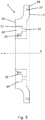
- Figure 5 schematically and in cross-sectional view shows an embodiment of the coupling element 7. It comprises a first coupling element surface 16 facing away from the rotational member 2 when the coupling assembly 1 is in use, and a second coupling element surface 17 facing towards the rotational member 2 when the coupling assembly 1 is in use. It further comprises an annular groove 18 arranged in the first coupling element surface 16. When the coupling element 7 is in use, the end section 3 of the hollow shaft 4 is arranged in the annular groove 18 as shown in figure 2 .
- the annular groove 18 comprises an outer groove surface 19 with a groove diameter corresponding to the outer shaft diameter D, a groove conical surface 20 matching the shrink ring conical surface, and a bottom surface 21.
- the connection between the shrink ring 6 and the coupling element 7 is established by first bolts 8 being inserted into a plurality of first threaded holes 25 extending at positions and orientations matching the plurality of first bores 15 of the shrink ring 6 when the coupling assembly 1 is in use.
- the shrink ring 6 and the coupling element 7 may be made from a number of materials, and the materials to use will be determined as part of the design process. One example would be 42CrMo4.
- the first bores 15 of the shrink ring 6 extend parallel to the rotational axis 5
- the shrink ring end surface 12 extends perpendicular to the rotational axis
- the first coupling element surface 16 extends perpendicular to the rotational axis
- the through-going second bores 22 extend parallel to the rotational axis.
- other orientations of the bores and or the surfaces are also covered by the invention as long as the overall functioning of the coupling assembly is accordance with the claimed invention.
- the shrink ring 6 is positioned and adapted to lock the hollow shaft 4 to the coupling element 7 by transferring torque between the neighbouring surfaces by friction by providing pressure to the surfaces of the interconnection.
- the pressure is provided by tightening the first bolts 8 whereby the shrink ring 6 and the coupling element 7 are mutually moved in a direction parallel to the rotational axis. Due to the conical surfaces 14,20, the compressional force increases as the first bolts 8 are tightened.
- the coupling element 7 further comprises an outer flange 26 extending in a direction away from the rotational axis 5.
- This outer flange 26 comprises at least a part of the second coupling element surface 17 to which the rotational member 2 is mounted.
- the part of the coupling element 7 where the heads of the second bolts 9 are placed after assembly is recessed.
- the geometry of a rotational member could allow the necessary space for the second bolts 9, so that the second coupling element surface 17 could be plane.
- the present invention was made in relation to wind turbines and for connecting the main shaft of the wind turbine to the planet carrier of a gearbox, such as a coaxial planetary gear.
- the torque to be transferred for this application is very large, and for this purpose, the connection between the planet carrier and the coupling element 7 will typically be made by a plurality of bolts.
- the coupling element 7 therefore further comprises a plurality of second threaded holes 27 extending from the second coupling element surface 17, the second threaded holes 27 being adapted to receive third bolts (not shown) for the establishment of the connection between the rotational member 2 and the hollow shaft 4 via the coupling assembly 1.
- the second threaded holes 27 are provided in the outer flange 26.
- the outer flange 26 could be provided with through-going third bores (not shown), and the corresponding threaded holes (not shown) could then be in the rotational member 2. This alternative would be advantageous for bulky rotational members 2 leaving too little space for insertion and tightening of the bolts.
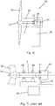
- Figure 6 schematically shows an example of a known wind turbine 28. It comprises a tower 29 with a nacelle 30 mounted thereon, a hub 31, at least two wind turbine blades 32 arranged on the hub 31, a gear box 33, a generator 34, and a main shaft 4 adapted to transfer a low speed rotational movement of the hub 31 to a high speed rotational movement of an input shaft 35 of the generator 34 via the gear box 33.
- the hub 31 has three blades 32 attached thereto.
- the torque to be transferred is resulting from a force provided by the wind to the blades 32 and via the main shaft 4. It also results from resistance provided by the system for generating energy.
- the connection should also be able to withstand the transferral of bending moments and axial loading due to the various forces involved in the operation of the wind turbine 28.
- Figure 7 schematically shows a drive train of a known wind turbine.
- the main shaft 4 is supported by two main bearings, called a front bearing 36 and a rear bearing 10, and the gear box 33 is supported by a third bearing 37 and a gear stay 44; the gear stay is shown schematically.
- This design has a high axial stiffness and an optimal load distribution between the front and rear bearings 36,10 also with respect to the position in relation to the tower 29.
- the set-up is statically over-determined, because there are more bearings than actually needed to be statically determined.
- FIG 8 schematically shows a drive train of a wind turbine 28 wherein the planet carrier is connected to the main shaft 4 via a coupling assembly 1 according to the present invention as described above.
- the planet carrier is not directly visible in figure 8 but is part of the gear box 33.
- the rear bearing 10 for supporting the main shaft 4 is arranged in the near proximity of the first coupling element surface 16 as more clearly shown in figures 2 and 3 .
- FIG. 9 An example of a specific design of a main shaft 4 for a wind turbine 28 and a coupling assembly 1 according to the present invention is shown in figure 9 .
- the rear main bearing 10 can be arranged very close to the coupling assembly 1, and the first coupling element surface 16 can be used for the correct mutual alignment of the components; this was explained above.
- the third bearing 37 and the gear stay 44 used in known drive trains can be avoided with the compact design of a coupling assembly according to the present invention.
- Calculations made in relation to the present invention have shown that the weight of the main shaft 4 can be reduced by in the order of 40% which is highly advantageous with respect to both amount of material used as well as the cost of transportation and handling. This has become possible, because the torque is to be transferred by both the shrink connection and the second bolts 9.
- the shrink connection is to carry less torque than for a known connection, and thereby less deformation of the main shaft 4 takes place during the establishment of the connection.
- This decrease in deformation as compared to known solutions is particularly advantageous for hollow shafts having a relatively small wall thickness.
- Figure 10 is a flow chart of a method of assembling an end section 3 of a main shaft 4 of a wind turbine 28 and a planet carrier 2 of a planetary gear system by use of a coupling assembly according to the present invention.
- the main shaft 4 is provided with third threaded holes 27 extending from an end surface 24 of the main shaft 4 and at positions and orientations matching the second bores 22 of the coupling element 7.
- the method comprising the following steps:
- the method may further comprise the step of mounting 43 the planet carrier 2 to the coupling element 7 by third bolts being screwed into the second threaded holes 27 in the outer flange 26.
Landscapes
- Engineering & Computer Science (AREA)
- General Engineering & Computer Science (AREA)
- Mechanical Engineering (AREA)
- Wind Motors (AREA)
Claims (15)
- Kupplungsanordnung (1) zum festen Verbinden eines Drehelements (2) mit einem Endabschnitt (3) einer Hohlwelle (4), wobei die Hohlwelle (4) eine Drehachse (5) aufweist und der Endabschnitt (3) einen inneren Wellendurchmesser (d) und einen äußeren Wellendurchmesser (D) aufweist, wobei die Kupplungsanordnung (1) umfasst:- einen Schrumpfring (6),- ein Kupplungselement (7),- eine Vielzahl von ersten Schrauben (8) und- eine Vielzahl von zweiten Schrauben (9);wobei der Schrumpfring (6) umfasst:- eine Schrumpfring-Endfläche (12), die vom Drehelement (2) abgewandt ist, wenn die Kupplungsanordnung (1) in Gebrauch ist,- eine Schrumpfring-Außenfläche (13) mit einem äußeren Schrumpfringdurchmesser, der dem inneren Wellendurchmesser (d) entspricht,- eine konische Schrumpfringfläche (14) und- eine Vielzahl von durchgehenden ersten Bohrungen (15), die in Umfangsrichtung angeordnet sind und zur Aufnahme der ersten Schrauben (8) ausgelegt sind, wobei sich die ersten Bohrungen (15) von der Schrumpfring-Endfläche (12) erstrecken;und wobei das Kupplungselement (7) umfasst:- eine Kupplungselementfläche (16), die vom Drehelement (2) abgewandt, wenn die Kupplungsanordnung (1) in Gebrauch ist,- eine zweite Kupplungselementfläche (17), die dem Drehelement (2) zugewandt ist, wenn die Kupplungsanordnung (1) in Gebrauch ist, dadurch gekennzeichnet, dass das Kupplungselement weiterhin umfasst:- eine Ringnut (18), die in der ersten Kupplungselementfläche (16) angeordnet ist, wobei die Ringnut (18) umfasst:• eine äußere Nutfläche (19) mit einem Nutdurchmesser, der dem äußeren Wellendurchmesser (D) entspricht,• eine konische Nutfläche (20), die mit der konischen Schrumpfringfläche (14) übereinstimmt, und• eine Bodenfläche (21),- eine Vielzahl von durchgehenden zweiten Bohrungen (22), die in Umfangsrichtung angeordnet sind und sich zwischen der Bodenfläche (21) der Nut (18) und der zweiten Kupplungselementfläche (17) erstrecken, und- eine Vielzahl von ersten Gewindebohrungen (25), die sich an Positionen und Ausrichtungen erstrecken, die mit der Vielzahl der ersten Bohrungen (15) des Schrumpfrings (6) übereinstimmen, wenn die Kupplungsanordnung (1) in Gebrauch ist.
- Kupplungsanordnung (1) nach einem der vorstehenden Ansprüche, wobei sich die ersten Bohrungen (15) des Schrumpfrings (6) parallel zur Drehachse (5) erstrecken, wenn die Kupplungsanordnung (1) in Gebrauch ist.
- Kupplungsanordnung (1) nach einem der vorstehenden Ansprüche, wobei sich die Schrumpfringendfläche (12) senkrecht zur Drehachse (5) erstreckt, wenn die Kupplungsanordnung (1) in Gebrauch ist.
- Kupplungsanordnung (1) nach einem der vorstehenden Ansprüche, wobei sich die erste Kupplungselementfläche (16) senkrecht zur Drehachse (5) erstrecken, wenn die Kupplungsanordnung (1) in Gebrauch ist.
- Kupplungsanordnung (1) nach einem der vorstehenden Ansprüche, wobei sich die durchgehenden zweiten Bohrungen (22) parallel zur Drehachse (5) erstrecken, wenn die Kupplungsanordnung (1) in Gebrauch ist.
- Kupplungsanordnung (1) nach einem der vorstehenden Ansprüche, wobei das Kupplungselement (7) weiterhin einen Außenflansch (26) umfasst, der sich in einer Richtung weg von der Drehachse (5) erstreckt, wobei der Außenflansch (26) mindestens einen Teil der zweiten Kupplungselementfläche (17) umfasst.
- Kupplungsanordnung (1) nach einem der vorstehenden Ansprüche, wobei das Kupplungselement (7) weiterhin eine Vielzahl von zweiten Gewindebohrungen (27) umfasst, die sich von der zweiten Kupplungselementfläche (17) erstrecken, wobei die zweiten Gewindebohrungen (27) ausgelegt sind, dritte Schrauben zur Herstellung der Verbindung zwischen dem Drehelement (2) und der Hohlwelle (4) aufzunehmen.
- Kupplungsanordnung (1) nach Anspruch 7, wenn abhängig von Anspruch 6, wobei die zweiten Gewindebohrungen (27) in dem Außenflansch (26) bereitgestellt sind.
- Kupplungsanordnung (1) nach einem der vorstehenden Ansprüche, wobei das Verhältnis zwischen dem inneren Wellendurchmesser (d) und dem äußeren Wellendurchmesser (D) 0,5 bis 0,95 wie 0,6 bis 0,95, vorzugsweise 0,8 bis 0,9 beträgt.
- Kupplungsanordnung (1) nach einem der vorstehenden Ansprüche, wobei das Drehelement (2) ein Planetenträger eines koaxialen Planetengetriebes ist.
- Windkraftanlage (28), umfassend:- einen Turm (29), eine auf dem Turm (29) befestigte Gondel (30), eine Nabe (31), mindestens zwei an der Nabe (31) angeordnete Windkraftanlagenblätter (32), ein Getriebe (33)), einen Generator (34) und- eine Hauptwelle (4), die ausgelegt ist, eine langsame Drehbewegung der Nabe (31) über das Getriebe (33) auf eine schnelle Drehbewegung einer Eingangswelle (35) des Generators (34) zu übertragen,wobei das Getriebe (33) ein Planetengetriebesystem umfasst, das einen Planetenträger (2) umfasst, und
wobei der Planetenträger (2) über eine Kupplungsanordnung (1) nach Anspruch 10 mit der Hauptwelle (4) verbunden ist. - Windkraftanlage (28) nach Anspruch 11, wobei das Planetengetriebesystem ein Koaxialgetriebesystem ist.
- Windkraftanlage (28) nach Anspruch 11 oder 12, wobei ein Hauptlager (10) zum Tragen der Hauptwelle (4) in unmittelbarer Nähe der ersten Kupplungselementfläche (16) angeordnet ist.
- Verfahren zum Zusammenbauen eines Endabschnitts (4) einer Hauptwelle (4) einer Windkraftanlage (28) und eines Planetenträgers (2) eines Planetengetriebesystems unter Verwendung einer Kupplungsanordnung (1) nach einem der vorstehenden Ansprüche, wobei die Hauptwelle (4) mit dritten Gewindebohrungen (23) versehen ist, die sich von einer Endfläche (24) der Hauptwelle (4) und an Positionen und Ausrichtungen erstrecken, die mit den zweiten Bohrungen (22) des Kupplungselements (7) übereinstimmen, wobei das Verfahren die folgenden Schritte umfasst:- Befestigen (38) des Schrumpfrings (6) am Kupplungselement (7) unter Verwendung der Vielzahl von ersten Schrauben (8),- Anordnen (39) des Endabschnitts (3) der Hauptwelle (4) in der Ringnut (18),- Befestigen (40) des Kupplungselements (7) am Endabschnitt (3) unter Verwendung der Vielzahl von zweiten Schrauben (9), die in die dritten Gewindebohrungen (23) eingeschraubt werden,- Anziehen (41) der Vielzahl von ersten Schrauben (8), um eine Schrumpfverbindung herzustellen, und- Befestigen (42) des Planetenträgers (2) am Kupplungselement (7).
- Verfahren nach Anspruch 14, wobei die Kupplungsanordnung (1) nach Anspruch 9 ist und wobei der Planetenträger (2) an dem Kupplungselement (7) befestigt wird, indem dritte Schrauben in die zweiten Gewindebohrungen (27) in dem Außenflansch (26) eingeschraubt werden.
Applications Claiming Priority (2)
| Application Number | Priority Date | Filing Date | Title |
|---|---|---|---|
| DKPA201670702 | 2016-09-14 | ||
| PCT/DK2017/050264 WO2018050184A1 (en) | 2016-09-14 | 2017-08-16 | Coupling assembly and wind turbine comprising such assembly |
Publications (2)
| Publication Number | Publication Date |
|---|---|
| EP3513086A1 EP3513086A1 (de) | 2019-07-24 |
| EP3513086B1 true EP3513086B1 (de) | 2020-07-22 |
Family
ID=61619050
Family Applications (1)
| Application Number | Title | Priority Date | Filing Date |
|---|---|---|---|
| EP17754605.8A Active EP3513086B1 (de) | 2016-09-14 | 2017-08-16 | Kupplungsanordnung und windturbine mit solch einer anordnung |
Country Status (4)
| Country | Link |
|---|---|
| US (1) | US10989250B2 (de) |
| EP (1) | EP3513086B1 (de) |
| ES (1) | ES2812707T3 (de) |
| WO (1) | WO2018050184A1 (de) |
Families Citing this family (4)
| Publication number | Priority date | Publication date | Assignee | Title |
|---|---|---|---|---|
| EP4043724A1 (de) * | 2021-02-11 | 2022-08-17 | Siemens Gamesa Renewable Energy Innovation & Technology S.L. | Windturbinenhauptwellenanordnung |
| CN113236492B (zh) * | 2021-05-27 | 2022-09-13 | 浙江工业职业技术学院 | 一种风能送料装置及换向装置 |
| CN116399586B (zh) * | 2023-03-23 | 2024-02-02 | 中国船舶集团有限公司第七0三研究所 | 一种端接式液压加载器 |
| CN116399583B (zh) | 2023-06-07 | 2023-10-17 | 哈尔滨船舶锅炉涡轮机研究所(中国船舶集团有限公司第七0三研究所) | 一种大功率重载行星齿轮背靠背试验台 |
Family Cites Families (9)
| Publication number | Priority date | Publication date | Assignee | Title |
|---|---|---|---|---|
| DE10310639A1 (de) | 2003-03-10 | 2004-09-23 | Volker Limbeck | Abtriebskonfiguration für Windenergieanlagen |
| FR2852369B1 (fr) | 2003-03-13 | 2006-01-06 | Eurocopter France | Systeme de bride d'accouplement pour arbre creux |
| DE102007056487A1 (de) | 2007-11-22 | 2009-05-28 | Wilhelm Landwehr | Wellenverbindung |
| US7946819B2 (en) | 2008-11-26 | 2011-05-24 | General Electric Company | Wind turbine drive shaft connection arrangement |
| DE102011081861A1 (de) * | 2011-05-17 | 2012-11-22 | Winergy Ag | Antriebssystem für eine Windkraftanlage |
| EP2565478A1 (de) * | 2011-08-29 | 2013-03-06 | Siemens Aktiengesellschaft | Spannnabenanordnung |
| US20120141200A1 (en) | 2011-09-29 | 2012-06-07 | General Electric Company | One-piece coupling for a wind turbine drive shaft |
| DE102013224191A1 (de) | 2013-11-27 | 2015-05-28 | Volkswagen Aktiengesellschaft | Welle-Nabe-Fügeverbindung und Verfahren zur Herstellung derselben |
| DK3001062T3 (en) * | 2014-09-26 | 2017-07-17 | Siemens Ag | overload clutch |
-
2017
- 2017-08-16 EP EP17754605.8A patent/EP3513086B1/de active Active
- 2017-08-16 US US16/324,282 patent/US10989250B2/en active Active
- 2017-08-16 WO PCT/DK2017/050264 patent/WO2018050184A1/en not_active Ceased
- 2017-08-16 ES ES17754605T patent/ES2812707T3/es active Active
Non-Patent Citations (1)
| Title |
|---|
| None * |
Also Published As
| Publication number | Publication date |
|---|---|
| EP3513086A1 (de) | 2019-07-24 |
| WO2018050184A1 (en) | 2018-03-22 |
| US10989250B2 (en) | 2021-04-27 |
| US20190203774A1 (en) | 2019-07-04 |
| ES2812707T3 (es) | 2021-03-18 |
Similar Documents
| Publication | Publication Date | Title |
|---|---|---|
| EP2334933B1 (de) | Windturbinenrotor | |
| EP3447282B1 (de) | Leistungsübertragungssystem für eine windenergieanlage | |
| US8197215B2 (en) | Drive train for a wind turbine | |
| EP2500564B1 (de) | Getriebe, Dichtungs- und Abdeckungsanordnungen | |
| US10989250B2 (en) | Coupling assembly and wind turbine comprising such assembly | |
| EP2372151B1 (de) | Windturbine | |
| EP2630368B1 (de) | Windturbine | |
| EP2553264B1 (de) | Windturbine | |
| EP2604857B1 (de) | Modulares Getriebe für eine Windturbine | |
| GB2479380A (en) | Wind or water turbine rotor | |
| US11927176B2 (en) | Bearing arrangement for a wind turbine and wind turbine | |
| CN105221340B (zh) | 一种紧凑型风力发电机组的改良结构 | |
| EP3899255B1 (de) | Generatorgetriebeanordnung für eine windturbine | |
| EP3807532B1 (de) | Antriebsstrangverbindung einer windturbine | |
| CN114922912A (zh) | 风力涡轮机主轴组件 | |
| JP2021523322A (ja) | ローター軸受ハウジング、及びローター軸受ハウジングを備える風力タービン | |
| US12234803B2 (en) | Wind turbine power transmission system | |
| EP2944805A1 (de) | Stauluftturbinenantriebswellengetriebe und lageranordnung |
Legal Events
| Date | Code | Title | Description |
|---|---|---|---|
| STAA | Information on the status of an ep patent application or granted ep patent |
Free format text: STATUS: UNKNOWN |
|
| STAA | Information on the status of an ep patent application or granted ep patent |
Free format text: STATUS: THE INTERNATIONAL PUBLICATION HAS BEEN MADE |
|
| PUAI | Public reference made under article 153(3) epc to a published international application that has entered the european phase |
Free format text: ORIGINAL CODE: 0009012 |
|
| STAA | Information on the status of an ep patent application or granted ep patent |
Free format text: STATUS: REQUEST FOR EXAMINATION WAS MADE |
|
| 17P | Request for examination filed |
Effective date: 20190411 |
|
| AK | Designated contracting states |
Kind code of ref document: A1 Designated state(s): AL AT BE BG CH CY CZ DE DK EE ES FI FR GB GR HR HU IE IS IT LI LT LU LV MC MK MT NL NO PL PT RO RS SE SI SK SM TR |
|
| AX | Request for extension of the european patent |
Extension state: BA ME |
|
| DAV | Request for validation of the european patent (deleted) | ||
| DAX | Request for extension of the european patent (deleted) | ||
| GRAP | Despatch of communication of intention to grant a patent |
Free format text: ORIGINAL CODE: EPIDOSNIGR1 |
|
| STAA | Information on the status of an ep patent application or granted ep patent |
Free format text: STATUS: GRANT OF PATENT IS INTENDED |
|
| INTG | Intention to grant announced |
Effective date: 20200211 |
|
| GRAS | Grant fee paid |
Free format text: ORIGINAL CODE: EPIDOSNIGR3 |
|
| GRAA | (expected) grant |
Free format text: ORIGINAL CODE: 0009210 |
|
| STAA | Information on the status of an ep patent application or granted ep patent |
Free format text: STATUS: THE PATENT HAS BEEN GRANTED |
|
| AK | Designated contracting states |
Kind code of ref document: B1 Designated state(s): AL AT BE BG CH CY CZ DE DK EE ES FI FR GB GR HR HU IE IS IT LI LT LU LV MC MK MT NL NO PL PT RO RS SE SI SK SM TR |
|
| REG | Reference to a national code |
Ref country code: GB Ref legal event code: FG4D |
|
| REG | Reference to a national code |
Ref country code: CH Ref legal event code: EP |
|
| REG | Reference to a national code |
Ref country code: DE Ref legal event code: R096 Ref document number: 602017020235 Country of ref document: DE |
|
| REG | Reference to a national code |
Ref country code: AT Ref legal event code: REF Ref document number: 1293672 Country of ref document: AT Kind code of ref document: T Effective date: 20200815 |
|
| REG | Reference to a national code |
Ref country code: IE Ref legal event code: FG4D |
|
| REG | Reference to a national code |
Ref country code: LT Ref legal event code: MG4D |
|
| REG | Reference to a national code |
Ref country code: AT Ref legal event code: MK05 Ref document number: 1293672 Country of ref document: AT Kind code of ref document: T Effective date: 20200722 |
|
| PG25 | Lapsed in a contracting state [announced via postgrant information from national office to epo] |
Ref country code: LT Free format text: LAPSE BECAUSE OF FAILURE TO SUBMIT A TRANSLATION OF THE DESCRIPTION OR TO PAY THE FEE WITHIN THE PRESCRIBED TIME-LIMIT Effective date: 20200722 Ref country code: PT Free format text: LAPSE BECAUSE OF FAILURE TO SUBMIT A TRANSLATION OF THE DESCRIPTION OR TO PAY THE FEE WITHIN THE PRESCRIBED TIME-LIMIT Effective date: 20201123 Ref country code: HR Free format text: LAPSE BECAUSE OF FAILURE TO SUBMIT A TRANSLATION OF THE DESCRIPTION OR TO PAY THE FEE WITHIN THE PRESCRIBED TIME-LIMIT Effective date: 20200722 Ref country code: SE Free format text: LAPSE BECAUSE OF FAILURE TO SUBMIT A TRANSLATION OF THE DESCRIPTION OR TO PAY THE FEE WITHIN THE PRESCRIBED TIME-LIMIT Effective date: 20200722 Ref country code: BG Free format text: LAPSE BECAUSE OF FAILURE TO SUBMIT A TRANSLATION OF THE DESCRIPTION OR TO PAY THE FEE WITHIN THE PRESCRIBED TIME-LIMIT Effective date: 20201022 Ref country code: NO Free format text: LAPSE BECAUSE OF FAILURE TO SUBMIT A TRANSLATION OF THE DESCRIPTION OR TO PAY THE FEE WITHIN THE PRESCRIBED TIME-LIMIT Effective date: 20201022 Ref country code: GR Free format text: LAPSE BECAUSE OF FAILURE TO SUBMIT A TRANSLATION OF THE DESCRIPTION OR TO PAY THE FEE WITHIN THE PRESCRIBED TIME-LIMIT Effective date: 20201023 Ref country code: FI Free format text: LAPSE BECAUSE OF FAILURE TO SUBMIT A TRANSLATION OF THE DESCRIPTION OR TO PAY THE FEE WITHIN THE PRESCRIBED TIME-LIMIT Effective date: 20200722 Ref country code: AT Free format text: LAPSE BECAUSE OF FAILURE TO SUBMIT A TRANSLATION OF THE DESCRIPTION OR TO PAY THE FEE WITHIN THE PRESCRIBED TIME-LIMIT Effective date: 20200722 |
|
| PG25 | Lapsed in a contracting state [announced via postgrant information from national office to epo] |
Ref country code: RS Free format text: LAPSE BECAUSE OF FAILURE TO SUBMIT A TRANSLATION OF THE DESCRIPTION OR TO PAY THE FEE WITHIN THE PRESCRIBED TIME-LIMIT Effective date: 20200722 Ref country code: LV Free format text: LAPSE BECAUSE OF FAILURE TO SUBMIT A TRANSLATION OF THE DESCRIPTION OR TO PAY THE FEE WITHIN THE PRESCRIBED TIME-LIMIT Effective date: 20200722 Ref country code: PL Free format text: LAPSE BECAUSE OF FAILURE TO SUBMIT A TRANSLATION OF THE DESCRIPTION OR TO PAY THE FEE WITHIN THE PRESCRIBED TIME-LIMIT Effective date: 20200722 Ref country code: IS Free format text: LAPSE BECAUSE OF FAILURE TO SUBMIT A TRANSLATION OF THE DESCRIPTION OR TO PAY THE FEE WITHIN THE PRESCRIBED TIME-LIMIT Effective date: 20201122 |
|
| REG | Reference to a national code |
Ref country code: ES Ref legal event code: FG2A Ref document number: 2812707 Country of ref document: ES Kind code of ref document: T3 Effective date: 20210318 |
|
| PG25 | Lapsed in a contracting state [announced via postgrant information from national office to epo] |
Ref country code: NL Free format text: LAPSE BECAUSE OF FAILURE TO SUBMIT A TRANSLATION OF THE DESCRIPTION OR TO PAY THE FEE WITHIN THE PRESCRIBED TIME-LIMIT Effective date: 20200722 |
|
| REG | Reference to a national code |
Ref country code: CH Ref legal event code: PL |
|
| REG | Reference to a national code |
Ref country code: DE Ref legal event code: R097 Ref document number: 602017020235 Country of ref document: DE |
|
| PG25 | Lapsed in a contracting state [announced via postgrant information from national office to epo] |
Ref country code: LI Free format text: LAPSE BECAUSE OF NON-PAYMENT OF DUE FEES Effective date: 20200831 Ref country code: LU Free format text: LAPSE BECAUSE OF NON-PAYMENT OF DUE FEES Effective date: 20200816 Ref country code: RO Free format text: LAPSE BECAUSE OF FAILURE TO SUBMIT A TRANSLATION OF THE DESCRIPTION OR TO PAY THE FEE WITHIN THE PRESCRIBED TIME-LIMIT Effective date: 20200722 Ref country code: DK Free format text: LAPSE BECAUSE OF FAILURE TO SUBMIT A TRANSLATION OF THE DESCRIPTION OR TO PAY THE FEE WITHIN THE PRESCRIBED TIME-LIMIT Effective date: 20200722 Ref country code: CH Free format text: LAPSE BECAUSE OF NON-PAYMENT OF DUE FEES Effective date: 20200831 Ref country code: CZ Free format text: LAPSE BECAUSE OF FAILURE TO SUBMIT A TRANSLATION OF THE DESCRIPTION OR TO PAY THE FEE WITHIN THE PRESCRIBED TIME-LIMIT Effective date: 20200722 Ref country code: EE Free format text: LAPSE BECAUSE OF FAILURE TO SUBMIT A TRANSLATION OF THE DESCRIPTION OR TO PAY THE FEE WITHIN THE PRESCRIBED TIME-LIMIT Effective date: 20200722 Ref country code: SM Free format text: LAPSE BECAUSE OF FAILURE TO SUBMIT A TRANSLATION OF THE DESCRIPTION OR TO PAY THE FEE WITHIN THE PRESCRIBED TIME-LIMIT Effective date: 20200722 Ref country code: IT Free format text: LAPSE BECAUSE OF FAILURE TO SUBMIT A TRANSLATION OF THE DESCRIPTION OR TO PAY THE FEE WITHIN THE PRESCRIBED TIME-LIMIT Effective date: 20200722 |
|
| REG | Reference to a national code |
Ref country code: BE Ref legal event code: MM Effective date: 20200831 |
|
| PLBE | No opposition filed within time limit |
Free format text: ORIGINAL CODE: 0009261 |
|
| STAA | Information on the status of an ep patent application or granted ep patent |
Free format text: STATUS: NO OPPOSITION FILED WITHIN TIME LIMIT |
|
| PG25 | Lapsed in a contracting state [announced via postgrant information from national office to epo] |
Ref country code: AL Free format text: LAPSE BECAUSE OF FAILURE TO SUBMIT A TRANSLATION OF THE DESCRIPTION OR TO PAY THE FEE WITHIN THE PRESCRIBED TIME-LIMIT Effective date: 20200722 |
|
| 26N | No opposition filed |
Effective date: 20210423 |
|
| PG25 | Lapsed in a contracting state [announced via postgrant information from national office to epo] |
Ref country code: SK Free format text: LAPSE BECAUSE OF FAILURE TO SUBMIT A TRANSLATION OF THE DESCRIPTION OR TO PAY THE FEE WITHIN THE PRESCRIBED TIME-LIMIT Effective date: 20200722 |
|
| PG25 | Lapsed in a contracting state [announced via postgrant information from national office to epo] |
Ref country code: BE Free format text: LAPSE BECAUSE OF NON-PAYMENT OF DUE FEES Effective date: 20200831 Ref country code: SI Free format text: LAPSE BECAUSE OF FAILURE TO SUBMIT A TRANSLATION OF THE DESCRIPTION OR TO PAY THE FEE WITHIN THE PRESCRIBED TIME-LIMIT Effective date: 20200722 Ref country code: IE Free format text: LAPSE BECAUSE OF NON-PAYMENT OF DUE FEES Effective date: 20200816 |
|
| REG | Reference to a national code |
Ref country code: NL Ref legal event code: MP Effective date: 20200722 |
|
| PG25 | Lapsed in a contracting state [announced via postgrant information from national office to epo] |
Ref country code: TR Free format text: LAPSE BECAUSE OF FAILURE TO SUBMIT A TRANSLATION OF THE DESCRIPTION OR TO PAY THE FEE WITHIN THE PRESCRIBED TIME-LIMIT Effective date: 20200722 Ref country code: MT Free format text: LAPSE BECAUSE OF FAILURE TO SUBMIT A TRANSLATION OF THE DESCRIPTION OR TO PAY THE FEE WITHIN THE PRESCRIBED TIME-LIMIT Effective date: 20200722 Ref country code: CY Free format text: LAPSE BECAUSE OF FAILURE TO SUBMIT A TRANSLATION OF THE DESCRIPTION OR TO PAY THE FEE WITHIN THE PRESCRIBED TIME-LIMIT Effective date: 20200722 |
|
| PG25 | Lapsed in a contracting state [announced via postgrant information from national office to epo] |
Ref country code: MK Free format text: LAPSE BECAUSE OF FAILURE TO SUBMIT A TRANSLATION OF THE DESCRIPTION OR TO PAY THE FEE WITHIN THE PRESCRIBED TIME-LIMIT Effective date: 20200722 Ref country code: MC Free format text: LAPSE BECAUSE OF FAILURE TO SUBMIT A TRANSLATION OF THE DESCRIPTION OR TO PAY THE FEE WITHIN THE PRESCRIBED TIME-LIMIT Effective date: 20200722 |
|
| P01 | Opt-out of the competence of the unified patent court (upc) registered |
Effective date: 20230521 |
|
| PGFP | Annual fee paid to national office [announced via postgrant information from national office to epo] |
Ref country code: ES Payment date: 20250916 Year of fee payment: 9 |
|
| PGFP | Annual fee paid to national office [announced via postgrant information from national office to epo] |
Ref country code: DE Payment date: 20250827 Year of fee payment: 9 |
|
| PGFP | Annual fee paid to national office [announced via postgrant information from national office to epo] |
Ref country code: GB Payment date: 20250826 Year of fee payment: 9 |
|
| PGFP | Annual fee paid to national office [announced via postgrant information from national office to epo] |
Ref country code: FR Payment date: 20250825 Year of fee payment: 9 |