EP3512997B1 - An apparatus for washing and dewatering pulp, a system for controlling such an apparatus, and a method for processing pulp in such an apparatus - Google Patents
An apparatus for washing and dewatering pulp, a system for controlling such an apparatus, and a method for processing pulp in such an apparatus Download PDFInfo
- Publication number
- EP3512997B1 EP3512997B1 EP17851180.4A EP17851180A EP3512997B1 EP 3512997 B1 EP3512997 B1 EP 3512997B1 EP 17851180 A EP17851180 A EP 17851180A EP 3512997 B1 EP3512997 B1 EP 3512997B1
- Authority
- EP
- European Patent Office
- Prior art keywords
- press
- threshold value
- press rolls
- pulp
- control
- Prior art date
- Legal status (The legal status is an assumption and is not a legal conclusion. Google has not performed a legal analysis and makes no representation as to the accuracy of the status listed.)
- Active
Links
Images



Classifications
-
- B—PERFORMING OPERATIONS; TRANSPORTING
- B30—PRESSES
- B30B—PRESSES IN GENERAL
- B30B15/00—Details of, or accessories for, presses; Auxiliary measures in connection with pressing
- B30B15/26—Program-control arrangements
-
- B—PERFORMING OPERATIONS; TRANSPORTING
- B30—PRESSES
- B30B—PRESSES IN GENERAL
- B30B9/00—Presses specially adapted for particular purposes
- B30B9/02—Presses specially adapted for particular purposes for squeezing-out liquid from liquid-containing material, e.g. juice from fruits, oil from oil-containing material
- B30B9/20—Presses specially adapted for particular purposes for squeezing-out liquid from liquid-containing material, e.g. juice from fruits, oil from oil-containing material using rotary pressing members, other than worms or screws, e.g. rollers, rings, discs
-
- D—TEXTILES; PAPER
- D21—PAPER-MAKING; PRODUCTION OF CELLULOSE
- D21C—PRODUCTION OF CELLULOSE BY REMOVING NON-CELLULOSE SUBSTANCES FROM CELLULOSE-CONTAINING MATERIALS; REGENERATION OF PULPING LIQUORS; APPARATUS THEREFOR
- D21C9/00—After-treatment of cellulose pulp, e.g. of wood pulp, or cotton linters ; Treatment of dilute or dewatered pulp or process improvement taking place after obtaining the raw cellulosic material and not provided for elsewhere
- D21C9/02—Washing ; Displacing cooking or pulp-treating liquors contained in the pulp by fluids, e.g. wash water or other pulp-treating agents
- D21C9/06—Washing ; Displacing cooking or pulp-treating liquors contained in the pulp by fluids, e.g. wash water or other pulp-treating agents in filters ; Washing of concentrated pulp, e.g. pulp mats, on filtering surfaces
-
- D—TEXTILES; PAPER
- D21—PAPER-MAKING; PRODUCTION OF CELLULOSE
- D21C—PRODUCTION OF CELLULOSE BY REMOVING NON-CELLULOSE SUBSTANCES FROM CELLULOSE-CONTAINING MATERIALS; REGENERATION OF PULPING LIQUORS; APPARATUS THEREFOR
- D21C9/00—After-treatment of cellulose pulp, e.g. of wood pulp, or cotton linters ; Treatment of dilute or dewatered pulp or process improvement taking place after obtaining the raw cellulosic material and not provided for elsewhere
- D21C9/18—De-watering; Elimination of cooking or pulp-treating liquors from the pulp
Definitions
- the present invention relates to a method for processing pulp, especially cellulose-containing pulp, in an apparatus for washing and dewatering pulp, especially cellulose-containing pulp, comprising two rotatable press rolls having a permeable outer surface, and a vat, in which the press rolls are installed, the press rolls defining a press nip between them, in which press nip the pulp is pressed, and the apparatus is arranged to feed the pulp in the direction of rotation of the press rolls through the press nip, at least one of the press rolls being movable in relation to the other press roll by means the press nip can be varied.
- the processing of the pulp in the apparatus is determined by variable operating parameters which are variable during operation.
- the present invention relates to a system for controlling an apparatus of the above-mentioned type.
- a roll press When producing cellulose-based products, a roll press is frequently used for washing and dewatering the cellulose-based pulp.
- the pulp is passed between two co-operating press rolls installed in the roll press, the press rolls having a perforated outer surface, a so-called mantle surface, whereby the outer surface is permeable to liquid pressed out of the pulp, and the pulp is pressed in the roll nip, or the press nip, between the press rolls, whereby liquid is pressed out of the pulp.
- the roll press also includes one or more washing zones and/or dewatering zones prior to the press nip.
- control systems for press roll apparatuses for washing of pulp is based on the torque and the rotation speed of the press rolls is adjusted to maintain a desired value of the torque. For example, if the output of the apparatus increases, the rotation speed of the rolls is increased in order to maintain the desired value of the torque.
- US 3,730,079 discloses a press comprising two press rolls rotatable about parallel axes, wherein one of the press rolls is laterally movable relative to the other to vary the cross-section of the therebetween press nip. Pressing force is applied to the laterally movable press roll by a plurality of separate link systems actuated by individual fluid pressure operated actuators. Pneumatically expansible tubes or springs are provided to urge the movable press roll away from the other. The object of this press is to maintain the axes of the press rolls parallel while permitting relative lateral movement of the press rolls.
- a system and method where the distance between the press rolls is a variable operating parameter, at least one desired value for a specific control parameter is set, the control parameters include the distance between the press rolls, the specific control parameter is measured the specific control parameter; and wherein the distance between the press rolls is adjusted during operation to keep the difference between the set desired value and the value of the measured specific control parameter below a certain level.
- WO2009075645 discloses a method for processing pulp in an apparatus for washing and dewatering pulp, the apparatus comprising two rotatable press rolls having a permeable outer surface, the press rolls defining a press nip between them, in which press nip the pulp is pressed, at least one of the press rolls being movable in relation to the other press roll to vary the press nip, the processing of the pulp in the apparatus being determined by variable operating parameters, where the distance between the press rolls is one of the operating parameters, to keep the difference between the set desired value and the value of the measured specific control parameter below a certain level.
- JPH3259846 discloses how a control part can be installed in wash press for controlling a driving means so as to drive a shaft center movable roller in the nip pressure relieving direction at a time when the detected value of a speed measuring means is less than the reference speed.
- WO2014109693 relates to an apparatus for washing and dewatering cellulose pulp, which apparatus comprises a first movable permeable surface, a pulp transportation chamber wall and a pulp transportation chamber, which has a chamber gap width between the pulp transportation chamber wall and the firs movable permeable surface, wherein the pulp transportation chamber is provided with a local throttle having a throttle gap width and a second permeable surface for initial dewatering is provided before the local throttle.
- WO9854401 relates to a device for dehydrating and washing suspensions of fibrous material, comprising two rollers turning in opposite directions, a material feeding element and a material discharge element, wherein the material feeding element is arranged separately in lower area of said rollers, a discharging endless screw is arranged below the gap between the two rollers for discharging a filtration mat, and a washing zone is provided in the upper area of the rollers.
- the present invention is based on the insight that high degree of flexibility, improved washing efficiency, capacity of the washing apparatus and production stability can be achieved by providing control methods and systems including a combination of adjustment of rotation speed of press rolls based on vat pressure and linear load, and adjustment of distance between the press rolls based on linear load and vat pressure.
- the adjustment of rotation speed is based on a first set of control rules and the adjustment of the distance is based on a second set of control rules.
- the adjustment of rotation speed is based on the vat pressure, linear load and torque.
- the rotation speed is controlled based on the control parameters vat pressure and linear load (and in preferred embodiments the torque) aims at successively bringing the respective control parameter to their respective predetermined (e.g. set by an operator) threshold value or as close as possible to that value at the same time as the rotation speed successively is reduced.
- the distance between the press rolls is controlled based on the control parameters vat pressure and linear load aims at successively bringing the respective control parameter to their respective predetermined (e.g. set by an operator) threshold value or threshold value or as close as possible to that value.
- the term “during operation” refers to during ongoing operation of the apparatus, i.e. the operating parameters are adjustable while the apparatus is continuously running, idle running or while pressing and washing pulp, without being forced to shut down the apparatus.
- the axes of rotation of the press rolls can be in substantially the same horizontal plane, and the movable press roll is then laterally movable in relation to the other, or the axes of rotation of the press rolls can be positioned in other ways.
- the axes of rotation of the press rolls can, for example, be in substantially the same vertical plane, and the movable press roll is then movable in a substantially vertical direction, upwards or downwards.
- a method for processing pulp in an apparatus for washing and dewatering pulp comprising two rotatable press rolls having a permeable outer surface, and a vat in which the press rolls are installed, the press rolls defining a press nip between them, in which press nip the pulp is pressed, and the apparatus is arranged to feed the pulp in the direction of rotation of the press rolls through the press nip, and the processing of the pulp in the apparatus is determined by at least two variable operating parameters which are variable during operation, wherein at least one of the press rolls is movable in relation to the other press roll to vary the press nip.
- the method includes the steps of:
- Throttle gap width refers to the variable opening gap of a throttle.
- the throttle is arranged close to or in the outlet of the pulp distribution device. Such a throttle is described in the international patent application WO 2014109693 .
- the torque is included as control parameter and a threshold value is associated with the torque.
- outlet consistency the flow rate of the pulp into the pulp distribution device and the ratio between the rotation speed of the press roll and the flow rate of the pulp into the pulp distribution device as control parameters.
- the adjustments of the at least two operating parameters aims at bringing the respective control parameter or at least one or some of the control parameters as close as possible to the respective threshold value, which may be set by the operator and may be set to a maximum desired value, for example, with regard to wear of, performance of, or process efficiency of the apparatus for washing and dewatering pulp. If the threshold value is a maximum value, the adjustments of operating parameters aim at bringing the control parameters close to their respective maximum value (i.e. the set threshold value).
- the first and second set of control process rules may include (however, the following rules are one exemplary and is a non-exhaustive list of rules):
- further rules include that the second set include, if a measured value of vat pressure or linear load and a respective threshold value deviates from each other, adjusting the distance between the press rolls such that the sum of the deviation between the vat pressure and the respective threshold value and the linear load and the respective threshold value is minimized.
- a system for controlling an apparatus for washing and dewatering pulp comprising two rotatable press rolls having a permeable outer surface, and a vat in which the press rolls are installed, the press rolls defining a press nip between them, in which press nip the pulp is pressed, and the apparatus is arranged to feed the pulp in the direction of rotation of the press rolls through the press nip, and the processing of the pulp in the apparatus is determined by at least one variable operating parameters which are variable during operation, at least one of the press rolls being movable in relation to the other press roll to vary the press nip.
- the rotation speed of the press roll and the distance between the press rolls are included as variable operating parameters.
- the system further comprises measuring means for measuring a value of control parameters, wherein vat pressure and linear load which acts on the pulp in the press nip are included as control parameters, an analysing device arranged to compare a measured value of a control parameter and a respective threshold value in order to identify deviations between them, wherein a desired maximum value is set as the predetermined threshold value for the respective control parameter, adjustments means for adjusting and/or maintaining the rotation speed during operation if deviations are identified during operation according to a first set of control process rules, wherein the rotation speed is reduced when the vat pressure and linear load are below their respective maximum values to reduce the difference between the measured value and maximum value, and adjustment means for, simultaneously with said adjustment means for adjusting and/or maintaining the rotation speed, adjusting the distance between the press rolls during operation according to a second set of control process rules if a linear load and/or vat pressure and a respective threshold value deviates from each other, wherein the distance between the press rolls is decreased if the linear load is below the maximum level and the vat pressure is at the
- the system comprises setting means for setting at least one threshold value for the respective control parameter, wherein in embodiments, also torque is included as a control parameter.
- outlet consistency the flow rate of the pulp into the pulp distribution device and the ratio between the rotation speed of the press roll and the flow rate of the pulp into the pulp distribution device as control parameters.
- system further comprises setting means for setting at least one threshold value for the respective control parameter.
- a controller is arranged to, according to the first set of control process rules, instruct the adjustments means to, if a measured value of a control parameter and a respective threshold value corresponds to each other, maintain the rotation speed of the press roll at present level.
- the adjustment means includes at least one hydraulic driving device for urging the movable press roll away from the other or towards each other.
- the controller is arranged to, according to the first set of control process rules, instruct the adjustments means to, if a measured value of a control parameter and a respective threshold value corresponds to each other for all control parameters, maintain the distance between the press rolls and the rotation speed of the press roll at present level.
- the controller is arranged to, according to the second set of control process rules, instruct the adjustments means to, if a measured value of vat pressure and linear load and a respective threshold value corresponds to each other, to maintain the distance between the press rolls and the rotation speed of the press roll at present level.
- the controller is arranged to, according to the first set of control process rules, instruct the adjustments means to, if a measured value is higher than the threshold value, instruct the adjustment means to increase the rotation speed of the press roll.
- the controller is arranged to, according to the first set of control process rules, instruct the adjustments means to, if a measured value of a control parameter and a respective threshold value deviates from each other and the measured values are below the respective threshold values, decrease the rotation speed of the press roll.
- the controller is arranged to, according to the second control process rules, instruct the adjustments means to, if a measured value of vat pressure or linear load and a respective threshold value deviates from each other, adjust the distance between the press rolls.
- the controller is arranged to, according to the second set of control process rules, instruct the adjustments means to, if a measured value of linear load and the respective threshold value deviates from each other and the threshold value and the measured value of the vat pressure corresponds to each other, decrease the distance between the press rolls.
- the controller is arranged to, according to the second set of control process rules, instruct the adjustments means to, if a measured value of linear load is below the threshold value and the measured value of the vat pressure and the respective threshold value corresponds to each other, decrease the distance between the press rolls.
- the controller is arranged to, according to the second set of control process rules, instruct the adjustments means to, if a measured value of vat pressure and the respective threshold value deviates from each other and the linear load corresponds to each other, increase the distance between the press rolls to reduce the difference to be below the predetermined level.
- the controller is arranged to, according to said second set of control process rules, instruct the adjustments means to, if a measured value of vat pressure is below the threshold value and the linear load and the respective threshold value corresponds to each other, increase the distance between the press rolls to reduce the difference to be below the predetermined level.
- the performance and the flexibility of the apparatus can be improved significantly.
- the present invention entails that the apparatus can be operated closer to the maximum values or limits of the control parameters, e.g. linear load and vat pressure, which provides a higher output consistency and an improved washing efficiency.
- the present invention enables a limitation of the linear load, in order to reduce wear, and/or in order to achieve a desired level of linear load in terms of process efficiency.
- the present invention also provides possibilities to reduce vat pressure in order to decrease fibre losses.
- Another advantage of the present invention is that it significantly reduces the need for manual surveillance since the adjustments operate automatically. This also eliminates differences between different operators and reduces the risk for unwanted production stops since the control system handles disturbances automatically.
- Yet another advantage of the present invention is that the present invention can be implemented in systems using the traditional approach for control, i.e. a control of the rotation speed only based on threshold value for the torque.
- the present invention achieves an improved washing efficiency, capacity of the washing apparatus and production stability.
- the threshold values for the control parameters can be set by the operator during the operation of the apparatus, and also changed during operation.
- the adjustment of the variable operating parameters can be performed according to different kinds of algorithms or techniques, depending on the number of variable operating parameters being adjusted. For example, several operating parameters can be adjusted simultaneously, or one operating parameter can be adjusted at a time, and thereafter another.
- At least one maximum value for the control parameters for example, vat pressure, torque and linear load are set as threshold value, and the variable operating parameters are adjusted during operation to bring them closer to or keep the control parameters at their respective maximum value. This further improves the performance and the flexibility of the apparatus, whereby a desired quality of the pressed pulp can be attained in a more efficient way.
- Fig. 1 schematically shows an embodiment of the apparatus for washing and dewatering cellulose-containing pulp according to the present invention provided with an embodiment of the system according to the present invention schematically illustrated with blocks. Also in WO 2014/109693 , an apparatus for washing and/or dewatering of pulp in which the present invention can be used is described, which hereby is incorporated with reference.
- the apparatus comprises a first rotatable press roll 102 and a second rotatable press roll 104, each press roll 102, 104 having a permeable outer surface 106, 108 which is perforated, i.e. provided with apertures, whereby the outer surface 106, 108 is permeable to filtrate pressed out of the pulp.
- the shape of the apertures is normally circular, but any shape is possible.
- the press rolls 102, 104 comprise a number of filtrate channels 110 radially inwards of the outer surface 106, 108 to lead evacuated filtrate away.
- the two press rolls 102, 104 defines a press/roll nip 112 between them, in which press nip 112 the pulp is pressed, and are arranged to rotate in opposite directions, the left press roll 102 being arranged to rotate in counter-clockwise direction and the right press roll 104 being arranged to rotate in clockwise direction.
- the apparatus is arranged to feed the pulp in the direction of rotation of the press rolls 102, 104 through the press nip 112.
- the axes of rotation of the press rolls 102, 104 being in substantially the same horizontal plane, and the apparatus is arranged to feed the pulp through the press nip 112 in a substantially vertical direction from below upwards.
- One of the press rolls 102, 104 herein the first press roll 102, is laterally movable in relation to the other press roll 104 to vary the press nip 112 under the operation of the apparatus.
- both press rolls 102, 104 are laterally movable to vary the press nip 112 under the operation of the apparatus.
- the processing of the pulp in the apparatus is determined by a set of variable operating parameters which are variable during operation.
- the apparatus comprises a casing which includes a vat 114, 116, 118 in which the press rolls 102, 104 are installed, the vat 114, 116, 118 partly enclosing the outer surface 106, 108 of each press roll 102, 104, whereby a gap 124, 125 for each press roll 102, 104 is defined, limited by the vat 114, 116, 118 and the outer surface 106, 108 of the respective press roll 102, 104.
- the vat 114, 116, 118 can be pressurized and comprises a first side vat segment 114 which partly encloses the outer surface 106 of the first press roll 102, and a second side vat segment 116 which partly encloses the outer surface 108 of the second press roll 104.
- Said casing comprises a first casing member 115 which extends between the ends of the first press roll 102 and to which the first side vat segment 114 is mounted, and a second casing member 117 which extends between the ends of the second press roll 104 and to which the second side vat segment 116 is mounted.
- the first casing members 115 is pivotable about a first axle 121 and the second casing members 117 is pivotable about a second axle 123, whereby the casing members 115, 117, together with their side vat segments 114, 116, are movable between a closed position and an opened position for providing access to the press rolls 102, 104.
- vat 114, 116, 118 comprises a central vat segment 118 partly enclosing the outer surface 106, 108 of the press rolls 102, 104 between the press nip 112 and the side vat segments 114, 116.
- the apparatus comprises a first pulp distribution device 126 for distributing pulp on the first press roll 102 and a second pulp distribution device 128 for distributing pulp on the second press roll 104.
- the pulp distribution devices 126, 128 are arranged to distribute pulp to the gap 124 along the whole length of each press roll 102, 104.
- the pulp distributed on the outer surface 106, 108 of the press roll 102, 104 forms a mat on the press rolls 102, 104.
- the pulp distribution device 126, 128 is in the form of a pulp distribution screw.
- the pulp distribution device 126, 128 can also comprise several separate pulp distribution means distributed one after the other along the longitudinal extension of the press roll 102, 104.
- Each pulp distribution device 126, 128 is connectable to a pulp supplying system via connection means 140, 142, and the supplying system supplies pulp to each pulp distribution device 126, 128.
- the apparatus also includes a pulp transport screw (not shown), which for example can be in the form of a pulp disintegrating screw or a shredder screw, towards which the pulp which has been pressed in the press nip 112 is conveyed.
- the pulp transport screw extends in parallel to the longitudinal axes of the press rolls 102, 104, and is arranged to disintegrate the pulp and transport the pulp axially away from the press for further processing.
- the system of the present invention is adapted to control the apparatus by controlling at least two variable operating parameters which are variable during operation and determine the processing of the pulp in the apparatus.
- the operating parameters includes:
- variable operating parameters can also be included such as:
- the system may comprise an operator unit 160 for setting at least one threshold value for a specific control parameter, the specific control parameter being included in a group of control parameters.
- the unit 160 is only schematically illustrated in Fig. 1 and may include an input means 162 via which the control parameters is set, and display means 164 for displaying the set control parameter.
- the setting means may be an operator unit, a stationary computer, a laptop, a mobile unit or any other device communicating with the system and enabling an operator to setting and adjusting threshold values.
- control parameters are included in said group:
- the system includes measuring means for measuring the specific control parameter, and the measuring means include means 168 for measuring the outlet pulp consistency, means 170 for measuring the vat pressure, means 172 for measuring the distance between the press rolls 102, 104, means 174 for measuring the torque of the press rolls 102, 104, means 175 for measuring the linear load, means 178 for measuring the rotation speed of the press roll 102, 104, means 180 for measuring the flow rate of the pulp into the pulp distribution device 126, 128, and means for 182 for measuring or calculating the above-mentioned ratio.
- Above-mentioned means for measuring are in the form of suitable sensors or equipment.
- the means 170 for measuring the vat pressure can be installed at various places in the vat, for example at lowest region/-s in the vat to measure the vat pressure there.
- the linear load can for example be measured by providing the means 175 for measuring the linear load in connection to the bearings of the press rolls 102, 104, and determine the linear load from the measured load on the bearings.
- the system includes adjustment means for adjusting one or several of the variable operating parameters of the set during operation.
- the adjustment means include means 214 for adjusting the rotation speed of the press rolls 102, 104 and means for adjusting the distance between the press rolls 102, 104, which means include hydraulic driving devices 202 for urging the laterally movable press roll 104 away from and towards the other press roll 102, and for providing and keeping a specific distance between the press rolls 102, 104 (see fig. 2 ).
- other means for adjusting the distance between the press rolls 102, 104 are possible, such as means based on electro-mechanics.
- the adjustment means is adapted to adjust two or more variable operating parameters.
- the adjustment means can be adapted to adjust several operating parameters simultaneously, or adapted to adjust one operating parameter at a time, and thereafter another.
- the adjustment means, the measuring means, the setting means and the display means are connected to a controller or control device 166 adapted to control or instruct the adjustment means and adapted to retrieve data from the measuring means and the setting means.
- the control device 166 comprises a processor 167 and storing means 169 for storing data.
- the control device 166 includes means 182 for performing calculations or an analysing device, for example, said ratio from the measurement of the means 180 for measuring the flow rate of the pulp from the pulp distribution device 126, 128 and the means 178 for measuring the rotation speed of the press roll 102, 104.
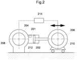
- Fig. 2 schematically illustrates an embodiment of the apparatus in which the present invention can be implemented, showing the pivotally mounting of the press rolls at the first end of the apparatus.
- the shaft 204 of the first press roll 102 and the shaft 206 of the second laterally movable press roll 104 are supported by bearings housed in bearing housings 208, 210.
- the bearing housing 208 of the first press roll 102 is fixedly attached to the casing 212 of the apparatus, and the bearing housing 210 of the laterally movable press roll 104 is movably attached to the casing 212, whereby the second press roll 104 is movable in relation to casing 212 and laterally movable in relation the other press roll 102.
- the hydraulic driving device 202 is positioned between the shafts 204, 206 of the press rolls 102, 104 and is connected to the bearing housing 208, 210 of each press roll 102, 104.
- a corresponding hydraulic driving device is mounted at the second end of the apparatus.
- the hydraulic driving devices 202 are adapted to urge the laterally movable press roll 104 away from the other press roll 102 and towards the other press roll 102 for providing a specific distance between the press rolls 102, 104 and for keeping this distance.
- the means 174 for measuring the linear load is in the form of a load cell 201 connected to the hydraulic driving device 202.
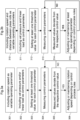
- Fig. 3a illustrates a method not according to the invention.
- Fig. 3b - 3c illustrates aspects of the method according to the present invention by way of schematic flow schedules, which methods are applicable to the apparatus shown in Fig. 1 and Fig. 2 , for example, but can also be applied to other apparatus for washing and dewatering cellulose-containing pulp comprising two movable press rolls.
- Fig. 3a the first control loop is generally shown.
- rotation speed of the press rolls is included as variable operating parameter, at 301.
- the torque and linear load and/or vat pressure is included as control parameters, at 302, and an operator may set a threshold value, e.g. a maximum value for each of them, at 303.
- a threshold value e.g. a maximum value for each of them.
- the specific control parameters are measured, at 304.
- measured values of control parameters and respective threshold value are compared to identify deviations between them. In practice, the measured value and the respective set threshold value is compared to identify whether the measured value is below or above the respective threshold value (taking into account any tolerance interval surrounding the threshold value). If no, i.e.
- one or several variable operating parameters of said set is/are adjusted according to a first set of control rules, at 306, to bring or align the control parameter closer to the respective threshold values for that control parameter. If yes, i.e. if the measured values and respective threshold values corresponds to each other, the process returns to step 304 and the operating parameters are maintained at present values or levels. During the running of the process, a user can manually adapt the setting of the control parameters.
- Fig. 3b an embodiment of the first and second control loops operating in synchronism is generally shown.
- the distance between the press rolls and the rotation speed of the press rolls are included as operating parameters.
- the vat pressure and linear load are included as control parameters.
- operator sets a threshold value, e.g. a maximum value for each of the control parameters.
- the specific control parameters are measured, at 313.
- measured values of control parameters and respective threshold value are compared to identify deviations. In practice, the measured value and the respective set threshold value is compared to identify whether the measured value is below or above the respective threshold value (taking into account any tolerance interval surrounding the threshold value). If no, i.e.
- variable operating parameters of said set is/are adjusted according to first and second set of control rules, at 315, to bring or align the control parameter closer to the respective threshold values for that control parameter. If yes, i.e. if the measured values and respective threshold values corresponds to each other, the process returns to step 313 and the operating parameters are maintained at present values or levels. During the running of the process, a user can manually adapt the setting of the control parameters.
- a further embodiment of the first and second control loops operating in synchronism is generally shown.
- the distance between the press rolls and the rotation speed of the press rolls are included as operating parameters.
- the vat pressure, linear load and torque are included as control parameters.
- operator sets a threshold value, e.g. a maximum value for each of the control parameters.
- the specific control parameters are measured, at 323.
- measured values of control parameters and respective threshold value are compared to identify deviations. In practice, the measured value and the respective set threshold value is compared to identify whether the measured value is below or above the respective threshold value (taking into account any tolerance interval surrounding the threshold value). If no, i.e.
- variable operating parameters of said set is/are adjusted according to first and second set of control rules, at 325, to bring or align the control parameter closer to the respective threshold values for that control parameter. If yes, i.e. if the measured values and respective threshold values corresponds to each other, the process returns to step 323 and the operating parameters are maintained at present values or levels. During the running of the process, a user can manually adapt the setting of the control parameters.
- Fig. 4 the first control loop for controlling the rotation speed of the press rolls based on torque, linear load and vat pressure is shown.
- the control loop for the rotation speed of the press rolls is based on at least one or a combination of any one of torque, linear load and vat pressure.
- Fig. 5 the second control loop for controlling the distance between the press rolls based on linear load and vat pressure is shown.
- the control loops for the rotation speed of the press rolls and the distance between the press rolls are combined and thereby the washing efficiency, capacity and stability of operation of the apparatus can be optimized.
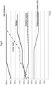
- FIG. 6 a simplified and schematic example operating scenario with the two control loops combined is illustrated.
- the maximum values for the control parameters linear load, torque and vat pressure are set, at 401, and the current values for the respective control parameters are measured at 402. If one of the measured values exceeds the maximum value or a predetermined highest level in relation to the maximum value (for example, the measured value may be allowed to be within a range about the maximum value), at 403, the rotation speed will be increased at 404. At the same time, as shown in Fig. 5 , the distance between the rolls will be adjusted only if it is the linear load or the vat pressure that deviates from the maximum value, see 505 - 509.
- the distance between the press rolls is increased, at 507.
- the vat pressure is at the maximum level or within the set tolerance and the linear load is not, at step 505 and 508, the distance between the press rolls is decreased, at 509.
- the rotation speed of the press rolls is maintained at 407.
- the distance between the press rolls will be adjusted if the linear load or the vat pressure is not at their respective maximum value as shown at 505 - 509, as described above. If all threshold values are below their maximum values, the rotation speed of the press rolls will be reduced at 405. At the same time, the distance between the press rolls will be increased or decreased depending on whether the linear load deviates from its maximum value, at 506, 507, or the vat pressure deviates from its maximum value, at 508, 509.
- Fig. 6 a simplified and schematic example where values of the control parameters, vat pressure, torque and linear load, are shown and how adjustments of the operating parameters, distance between the press rolls and the rotation speed of the press rolls, affects the control parameters over time.
Landscapes
- Engineering & Computer Science (AREA)
- Life Sciences & Earth Sciences (AREA)
- Wood Science & Technology (AREA)
- Mechanical Engineering (AREA)
- Paper (AREA)
Description
- The present invention relates to a method for processing pulp, especially cellulose-containing pulp, in an apparatus for washing and dewatering pulp, especially cellulose-containing pulp, comprising two rotatable press rolls having a permeable outer surface, and a vat, in which the press rolls are installed, the press rolls defining a press nip between them, in which press nip the pulp is pressed, and the apparatus is arranged to feed the pulp in the direction of rotation of the press rolls through the press nip, at least one of the press rolls being movable in relation to the other press roll by means the press nip can be varied. The processing of the pulp in the apparatus is determined by variable operating parameters which are variable during operation. Further, the present invention relates to a system for controlling an apparatus of the above-mentioned type.
- When producing cellulose-based products, a roll press is frequently used for washing and dewatering the cellulose-based pulp. The pulp is passed between two co-operating press rolls installed in the roll press, the press rolls having a perforated outer surface, a so-called mantle surface, whereby the outer surface is permeable to liquid pressed out of the pulp, and the pulp is pressed in the roll nip, or the press nip, between the press rolls, whereby liquid is pressed out of the pulp. The roll press also includes one or more washing zones and/or dewatering zones prior to the press nip. One example of such a roll press is disclosed in
EP 1 035 250 , where the central axes of the press rolls are lying in substantially the same horizontal plane, and the pulp is fed in the direction of rotation of the press rolls through the press nip and the pulp is passing the press nip between the press rolls from below upwards. - Mainly, even if there exist other types of control systems such as systems based on output from apparatus, control systems for press roll apparatuses for washing of pulp is based on the torque and the rotation speed of the press rolls is adjusted to maintain a desired value of the torque. For example, if the output of the apparatus increases, the rotation speed of the rolls is increased in order to maintain the desired value of the torque.
- A number of attempts to improve output and washing efficiency has been made. For example,
US 3,730,079 discloses a press comprising two press rolls rotatable about parallel axes, wherein one of the press rolls is laterally movable relative to the other to vary the cross-section of the therebetween press nip. Pressing force is applied to the laterally movable press roll by a plurality of separate link systems actuated by individual fluid pressure operated actuators. Pneumatically expansible tubes or springs are provided to urge the movable press roll away from the other. The object of this press is to maintain the axes of the press rolls parallel while permitting relative lateral movement of the press rolls. - In SE 532099 a system and method is disclosed where the distance between the press rolls is a variable operating parameter, at least one desired value for a specific control parameter is set, the control parameters include the distance between the press rolls, the specific control parameter is measured the specific control parameter; and wherein the distance between the press rolls is adjusted during operation to keep the difference between the set desired value and the value of the measured specific control parameter below a certain level.
- However, there is still a need for improved and more flexible methods and systems for processing of pulp in an apparatus for washing and dewatering pulp comprising two rotatable press rolls, which more accurately provides pulp with the quality which is desired, and which increases the capacity of the apparatus.
-
WO2009075645 discloses a method for processing pulp in an apparatus for washing and dewatering pulp, the apparatus comprising two rotatable press rolls having a permeable outer surface, the press rolls defining a press nip between them, in which press nip the pulp is pressed, at least one of the press rolls being movable in relation to the other press roll to vary the press nip, the processing of the pulp in the apparatus being determined by variable operating parameters, where the distance between the press rolls is one of the operating parameters, to keep the difference between the set desired value and the value of the measured specific control parameter below a certain level. - JPH3259846 discloses how a control part can be installed in wash press for controlling a driving means so as to drive a shaft center movable roller in the nip pressure relieving direction at a time when the detected value of a speed measuring means is less than the reference speed.
-
WO2014109693 relates to an apparatus for washing and dewatering cellulose pulp, which apparatus comprises a first movable permeable surface, a pulp transportation chamber wall and a pulp transportation chamber, which has a chamber gap width between the pulp transportation chamber wall and the firs movable permeable surface, wherein the pulp transportation chamber is provided with a local throttle having a throttle gap width and a second permeable surface for initial dewatering is provided before the local throttle. -
WO9854401 - The present invention is based on the insight that high degree of flexibility, improved washing efficiency, capacity of the washing apparatus and production stability can be achieved by providing control methods and systems including a combination of adjustment of rotation speed of press rolls based on vat pressure and linear load, and adjustment of distance between the press rolls based on linear load and vat pressure. The adjustment of rotation speed is based on a first set of control rules and the adjustment of the distance is based on a second set of control rules.
- In preferred embodiments, the adjustment of rotation speed is based on the vat pressure, linear load and torque.
- Generally, the rotation speed is controlled based on the control parameters vat pressure and linear load (and in preferred embodiments the torque) aims at successively bringing the respective control parameter to their respective predetermined (e.g. set by an operator) threshold value or as close as possible to that value at the same time as the rotation speed successively is reduced. The distance between the press rolls is controlled based on the control parameters vat pressure and linear load aims at successively bringing the respective control parameter to their respective predetermined (e.g. set by an operator) threshold value or threshold value or as close as possible to that value.
- According to an object of the present invention, there is provided methods and systems for improving washing efficiency, capacity of the washing apparatus and production stability.
- These and other objects are achieved in accordance with the appended claims.
- In the context of the present invention, the term "during operation" refers to during ongoing operation of the apparatus, i.e. the operating parameters are adjustable while the apparatus is continuously running, idle running or while pressing and washing pulp, without being forced to shut down the apparatus. The axes of rotation of the press rolls can be in substantially the same horizontal plane, and the movable press roll is then laterally movable in relation to the other, or the axes of rotation of the press rolls can be positioned in other ways. The axes of rotation of the press rolls can, for example, be in substantially the same vertical plane, and the movable press roll is then movable in a substantially vertical direction, upwards or downwards.
- According to an aspect of the present invention, there is provided a method for processing pulp in an apparatus for washing and dewatering pulp comprising two rotatable press rolls having a permeable outer surface, and a vat in which the press rolls are installed, the press rolls defining a press nip between them, in which press nip the pulp is pressed, and the apparatus is arranged to feed the pulp in the direction of rotation of the press rolls through the press nip, and the processing of the pulp in the apparatus is determined by at least two variable operating parameters which are variable during operation, wherein at least one of the press rolls is movable in relation to the other press roll to vary the press nip. The method includes the steps of:
- including the rotation speed of the press roll and the distance between the press rolls as variable operating parameters;
- including vat pressure and linear load as control parameters which act on the pulp in the press nip as control parameters, each being associated with a predetermined threshold value wherein a desired maximum value is set as the predetermined threshold value for the respective control parameter;
- measuring the control parameters;
- comparing measured control parameters and respective predetermined threshold value;
- if a measured control parameter and a respective threshold deviates (often, during operation, a deviation means that the measured value is lower than the threshold value but under certain conditions the deviation may be that the measured value exceeds the threshold value) from each other, adjusting and/or maintaining the rotation speed during operation according to a first set of control process rules wherein the rotation speed is reduced when the vat pressure and linear load are below their respective maximum values to reduce the difference between the measured value and maximum value;
- if a measured value of a linear load and/or vat pressure and a respective threshold value deviates from each other, adjusting the distance between the press rolls during operation according to a second set of control process rules, wherein the distance between the press rolls is decreased if the linear load is below the maximum level and the vat pressure is at the maximum level and the distance between the press rolls is increased if the vat pressure is below the maximum level and the linear load is at the maximum level,
wherein said second set of control process rules are operated in synchronism with said first set of control process rules. - In embodiments, it is also conceivable to include, for example, the pressure of the pulp distribution device or the throttle gap width as control parameters. Throttle gap width refers to the variable opening gap of a throttle. For example, the throttle is arranged close to or in the outlet of the pulp distribution device. Such a throttle is described in the
international patent application WO 2014109693 . - In preferred embodiments, the torque is included as control parameter and a threshold value is associated with the torque.
- Further, it conceivable to include outlet consistency, the flow rate of the pulp into the pulp distribution device and the ratio between the rotation speed of the press roll and the flow rate of the pulp into the pulp distribution device as control parameters.
- In preferred embodiments of the present invention, the adjustments of the at least two operating parameters aims at bringing the respective control parameter or at least one or some of the control parameters as close as possible to the respective threshold value, which may be set by the operator and may be set to a maximum desired value, for example, with regard to wear of, performance of, or process efficiency of the apparatus for washing and dewatering pulp. If the threshold value is a maximum value, the adjustments of operating parameters aim at bringing the control parameters close to their respective maximum value (i.e. the set threshold value).
- According to embodiments, the first and second set of control process rules may include (however, the following rules are one exemplary and is a non-exhaustive list of rules):
- the first set may include, if a measured value of at least one control parameter and a respective threshold value corresponds to each other, maintaining the rotation speed of the press roll at present level;
- the first and second set may include, if a measured value of a control parameter and a respective threshold value corresponds to each other for all control parameters, maintaining the distance between the press rolls and the rotation speed of the press roll at present level;
- the first and second set may include, if a measured value of vat pressure and linear load and a respective threshold value corresponds to each other, maintaining the distance between the press rolls and the rotation speed of the press roll at a present level. However, if the torque (or pressure in the pulp distribution device) at the same time exceeds the threshold, the rotation speed should be increased;
- the first set may include, if a measured value is higher than the threshold value, increasing the rotation speed of the press roll;
- the first set may include, if a measured value of a control parameter and a respective threshold value deviates from each other and the measured values all are below the respective threshold values, decreasing the rotation speed of the press roll;
- the second set may include, if a measured value of vat pressure or linear load and a respective threshold value deviates from each other, adjusting the distance between the press rolls;
- the second set may include, if a measured value of linear load and the respective threshold value deviates from each other and the threshold value and the measured value of the vat pressure corresponds to each other, decreasing the distance between the press rolls;
- the second set may include, If a measured value of the linear load is lower than the threshold value, and the threshold value and the measured value of the vat pressure corresponds to each other, decreasing the distance between the press rolls;
- the second set may include, if a measured value of vat pressure and the respective threshold value deviates from each other and the linear load and the threshold value corresponds to each other, increasing the distance between the press rolls;
- the second set may include, if a measured value of vat pressure is lower than threshold value and the linear load corresponds to the threshold value, increasing the distance between the press rolls.
- The examples above, is a non-exhaustive list of process rules. For example, further rules include that the second set include, if a measured value of vat pressure or linear load and a respective threshold value deviates from each other, adjusting the distance between the press rolls such that the sum of the deviation between the vat pressure and the respective threshold value and the linear load and the respective threshold value is minimized.
- According to a further aspect of the present invention, there is provided a system for controlling an apparatus for washing and dewatering pulp comprising two rotatable press rolls having a permeable outer surface, and a vat in which the press rolls are installed, the press rolls defining a press nip between them, in which press nip the pulp is pressed, and the apparatus is arranged to feed the pulp in the direction of rotation of the press rolls through the press nip, and the processing of the pulp in the apparatus is determined by at least one variable operating parameters which are variable during operation, at least one of the press rolls being movable in relation to the other press roll to vary the press nip. The rotation speed of the press roll and the distance between the press rolls are included as variable operating parameters. The system further comprises measuring means for measuring a value of control parameters, wherein vat pressure and linear load which acts on the pulp in the press nip are included as control parameters, an analysing device arranged to compare a measured value of a control parameter and a respective threshold value in order to identify deviations between them, wherein a desired maximum value is set as the predetermined threshold value for the respective control parameter, adjustments means for adjusting and/or maintaining the rotation speed during operation if deviations are identified during operation according to a first set of control process rules, wherein the rotation speed is reduced when the vat pressure and linear load are below their respective maximum values to reduce the difference between the measured value and maximum value, and adjustment means for, simultaneously with said adjustment means for adjusting and/or maintaining the rotation speed, adjusting the distance between the press rolls during operation according to a second set of control process rules if a linear load and/or vat pressure and a respective threshold value deviates from each other, wherein the distance between the press rolls is decreased if the linear load is below the maximum level and the vat pressure is at the maximum level and the distance between the press rolls is increased if the vat pressure is below the maximum level and the linear load is at the maximum level, wherein said second set of control process rules are operated in synchronism with said first set of control process rules.
- It is also possible to include, for example, the pressure of the pulp distribution device or the throttle gap width as operating parameters.
- In embodiments, the system comprises setting means for setting at least one threshold value for the respective control parameter, wherein in embodiments, also torque is included as a control parameter.
- Further, it is also possible to include outlet consistency, the flow rate of the pulp into the pulp distribution device and the ratio between the rotation speed of the press roll and the flow rate of the pulp into the pulp distribution device as control parameters.
- In embodiments of the present invention, the system further comprises setting means for setting at least one threshold value for the respective control parameter.
- In embodiments of the present invention, a controller is arranged to, according to the first set of control process rules, instruct the adjustments means to, if a measured value of a control parameter and a respective threshold value corresponds to each other, maintain the rotation speed of the press roll at present level.
- In embodiments of the present invention, the adjustment means includes at least one hydraulic driving device for urging the movable press roll away from the other or towards each other.
- In embodiments of the present invention, the controller is arranged to, according to the first set of control process rules, instruct the adjustments means to, if a measured value of a control parameter and a respective threshold value corresponds to each other for all control parameters, maintain the distance between the press rolls and the rotation speed of the press roll at present level.
- In embodiments of the present invention, the controller is arranged to, according to the second set of control process rules, instruct the adjustments means to, if a measured value of vat pressure and linear load and a respective threshold value corresponds to each other, to maintain the distance between the press rolls and the rotation speed of the press roll at present level.
- In embodiments of the present invention, the controller is arranged to, according to the first set of control process rules, instruct the adjustments means to, if a measured value is higher than the threshold value, instruct the adjustment means to increase the rotation speed of the press roll.
- In embodiments of the present invention, the controller is arranged to, according to the first set of control process rules, instruct the adjustments means to, if a measured value of a control parameter and a respective threshold value deviates from each other and the measured values are below the respective threshold values, decrease the rotation speed of the press roll.
- In embodiments of the present invention, the controller is arranged to, according to the second control process rules, instruct the adjustments means to, if a measured value of vat pressure or linear load and a respective threshold value deviates from each other, adjust the distance between the press rolls.
- In embodiments of the present invention, the controller is arranged to, according to the second set of control process rules, instruct the adjustments means to, if a measured value of linear load and the respective threshold value deviates from each other and the threshold value and the measured value of the vat pressure corresponds to each other, decrease the distance between the press rolls.
- In embodiments of the present invention, the controller is arranged to, according to the second set of control process rules, instruct the adjustments means to, if a measured value of linear load is below the threshold value and the measured value of the vat pressure and the respective threshold value corresponds to each other, decrease the distance between the press rolls.
- In embodiments of the present invention, the controller is arranged to, according to the second set of control process rules, instruct the adjustments means to, if a measured value of vat pressure and the respective threshold value deviates from each other and the linear load corresponds to each other, increase the distance between the press rolls to reduce the difference to be below the predetermined level.
- In embodiments of the present invention, the controller is arranged to, according to said second set of control process rules, instruct the adjustments means to, if a measured value of vat pressure is below the threshold value and the linear load and the respective threshold value corresponds to each other, increase the distance between the press rolls to reduce the difference to be below the predetermined level.
- By the present invention, the performance and the flexibility of the apparatus can be improved significantly. For example, the present invention entails that the apparatus can be operated closer to the maximum values or limits of the control parameters, e.g. linear load and vat pressure, which provides a higher output consistency and an improved washing efficiency. Further examples of advantages include that the present invention enables a limitation of the linear load, in order to reduce wear, and/or in order to achieve a desired level of linear load in terms of process efficiency. The present invention also provides possibilities to reduce vat pressure in order to decrease fibre losses.
- Another advantage of the present invention is that it significantly reduces the need for manual surveillance since the adjustments operate automatically. This also eliminates differences between different operators and reduces the risk for unwanted production stops since the control system handles disturbances automatically.
- Yet another advantage of the present invention is that the present invention can be implemented in systems using the traditional approach for control, i.e. a control of the rotation speed only based on threshold value for the torque.
- In total, the present invention achieves an improved washing efficiency, capacity of the washing apparatus and production stability.
- The threshold values for the control parameters can be set by the operator during the operation of the apparatus, and also changed during operation. The adjustment of the variable operating parameters can be performed according to different kinds of algorithms or techniques, depending on the number of variable operating parameters being adjusted. For example, several operating parameters can be adjusted simultaneously, or one operating parameter can be adjusted at a time, and thereafter another.
- According to an advantageous embodiment of the present invention, at least one maximum value for the control parameters, for example, vat pressure, torque and linear load are set as threshold value, and the variable operating parameters are adjusted during operation to bring them closer to or keep the control parameters at their respective maximum value. This further improves the performance and the flexibility of the apparatus, whereby a desired quality of the pressed pulp can be attained in a more efficient way.
- Further advantageous embodiment of the apparatus according to the present invention emerge from the dependent claims and the detailed description of preferred embodiments.
- The present invention will now be described, for exemplary purposes, in more detail by way of embodiments and with reference to the enclosed drawings, in which:
- Fig. 1
- is a schematic view of an embodiment of the apparatus for washing and dewatering pulp provided with an embodiment of the system for controlling it according to present invention,
- Fig. 2
- is a schematic view illustrating a part of the embodiment of the apparatus according to the present invention,
- Fig. 3a
- is a schematic flow schedule illustrating aspects of a method not according to the present invention,
- Fig. 3b
- is a schematic flow schedule illustrating further aspects of the method according to the present invention,
- Fig. 3c
- is a schematic flow schedule illustrating further aspects of the method according to the present invention,
- Fig. 4
- is a schematic flow schedule illustrating further aspects of the method according to the present invention,
- Fig. 5
- is a schematic flow schedule illustrating further aspects of the method according to the present invention, and
- Fig. 6
- is a simplified and schematic diagram shown an example of how control parameters may vary over time depending on adjustment of operating parameters under certain operating conditions.
-
Fig. 1 schematically shows an embodiment of the apparatus for washing and dewatering cellulose-containing pulp according to the present invention provided with an embodiment of the system according to the present invention schematically illustrated with blocks. Also inWO 2014/109693 , an apparatus for washing and/or dewatering of pulp in which the present invention can be used is described, which hereby is incorporated with reference. - The apparatus comprises a first
rotatable press roll 102 and a secondrotatable press roll 104, eachpress roll outer surface outer surface filtrate channels 110 radially inwards of theouter surface left press roll 102 being arranged to rotate in counter-clockwise direction and theright press roll 104 being arranged to rotate in clockwise direction. The apparatus is arranged to feed the pulp in the direction of rotation of the press rolls 102, 104 through the press nip 112. The axes of rotation of the press rolls 102, 104 being in substantially the same horizontal plane, and the apparatus is arranged to feed the pulp through the press nip 112 in a substantially vertical direction from below upwards. One of the press rolls 102, 104, herein thefirst press roll 102, is laterally movable in relation to theother press roll 104 to vary the press nip 112 under the operation of the apparatus. In other embodiments of the press, both press rolls 102, 104 are laterally movable to vary the press nip 112 under the operation of the apparatus. The processing of the pulp in the apparatus is determined by a set of variable operating parameters which are variable during operation. - The apparatus comprises a casing which includes a
vat vat outer surface press roll gap press roll vat outer surface respective press roll vat side vat segment 114 which partly encloses theouter surface 106 of thefirst press roll 102, and a secondside vat segment 116 which partly encloses theouter surface 108 of thesecond press roll 104. - Said casing comprises a
first casing member 115 which extends between the ends of thefirst press roll 102 and to which the firstside vat segment 114 is mounted, and asecond casing member 117 which extends between the ends of thesecond press roll 104 and to which the secondside vat segment 116 is mounted. Thefirst casing members 115 is pivotable about afirst axle 121 and thesecond casing members 117 is pivotable about asecond axle 123, whereby thecasing members side vat segments vat central vat segment 118 partly enclosing theouter surface side vat segments - The apparatus comprises a first
pulp distribution device 126 for distributing pulp on thefirst press roll 102 and a secondpulp distribution device 128 for distributing pulp on thesecond press roll 104. Thepulp distribution devices gap 124 along the whole length of eachpress roll outer surface press roll pulp distribution device pulp distribution device press roll pulp distribution device pulp distribution device - The apparatus also includes a pulp transport screw (not shown), which for example can be in the form of a pulp disintegrating screw or a shredder screw, towards which the pulp which has been pressed in the press nip 112 is conveyed. The pulp transport screw extends in parallel to the longitudinal axes of the press rolls 102, 104, and is arranged to disintegrate the pulp and transport the pulp axially away from the press for further processing.
- The system of the present invention is adapted to control the apparatus by controlling at least two variable operating parameters which are variable during operation and determine the processing of the pulp in the apparatus. According to the invention, the operating parameters includes:
- the rotation speed of the press rolls 102, 104, which is used in the first control loop;
- the distance between the press rolls 102, 104, which corresponds to the cross-section of the press-
nip 112, which is used in the second control loop. - The first and second control loop is run in synchronism, both operating parameters are hence used. In addition, further variable operating parameters can also be included such as:
- pressure in the
pulp distribution device - Throttle gap width, which refers to the opening gap of a throttle arranged close to or in the outlet of the pulp distribution device. This is, for example, described in the
international patent application WO 2014109693 . - The system may comprise an
operator unit 160 for setting at least one threshold value for a specific control parameter, the specific control parameter being included in a group of control parameters. Theunit 160 is only schematically illustrated inFig. 1 and may include an input means 162 via which the control parameters is set, and display means 164 for displaying the set control parameter. In embodiments, the setting means may be an operator unit, a stationary computer, a laptop, a mobile unit or any other device communicating with the system and enabling an operator to setting and adjusting threshold values. - According to preferred embodiments of the present invention, the following control parameters are included in said group:
- the torque of the press rolls 102, 104;
- the linear load which acts on the pulp in the press nip 112 and is affected by the torque of the press rolls 102, 104; and/or
- the vat pressure, i.e. the pressure within the vat, (and/or pressure at inlet of vat).
- outlet consistency;
- the flow rate of the pulp into the
pulp distribution device - the ratio between the rotation speed of the
press roll pulp distribution device - The system includes measuring means for measuring the specific control parameter, and the measuring means include means 168 for measuring the outlet pulp consistency, means 170 for measuring the vat pressure, means 172 for measuring the distance between the press rolls 102, 104, means 174 for measuring the torque of the press rolls 102, 104, means 175 for measuring the linear load, means 178 for measuring the rotation speed of the
press roll pulp distribution device means 175 for measuring the linear load in connection to the bearings of the press rolls 102, 104, and determine the linear load from the measured load on the bearings. - The system includes adjustment means for adjusting one or several of the variable operating parameters of the set during operation. The adjustment means include means 214 for adjusting the rotation speed of the press rolls 102, 104 and means for adjusting the distance between the press rolls 102, 104, which means include
hydraulic driving devices 202 for urging the laterallymovable press roll 104 away from and towards theother press roll 102, and for providing and keeping a specific distance between the press rolls 102, 104 (seefig. 2 ). However, other means for adjusting the distance between the press rolls 102, 104 are possible, such as means based on electro-mechanics. - The adjustment means is adapted to adjust two or more variable operating parameters. When adjusting two or more variable operating parameters, the adjustment means can be adapted to adjust several operating parameters simultaneously, or adapted to adjust one operating parameter at a time, and thereafter another.
- The adjustment means, the measuring means, the setting means and the display means are connected to a controller or
control device 166 adapted to control or instruct the adjustment means and adapted to retrieve data from the measuring means and the setting means. Thecontrol device 166 comprises aprocessor 167 and storing means 169 for storing data. Thecontrol device 166 includesmeans 182 for performing calculations or an analysing device, for example, said ratio from the measurement of themeans 180 for measuring the flow rate of the pulp from thepulp distribution device means 178 for measuring the rotation speed of thepress roll -
Fig. 2 schematically illustrates an embodiment of the apparatus in which the present invention can be implemented, showing the pivotally mounting of the press rolls at the first end of the apparatus. Theshaft 204 of thefirst press roll 102 and theshaft 206 of the second laterallymovable press roll 104 are supported by bearings housed in bearinghousings housing 208 of thefirst press roll 102 is fixedly attached to thecasing 212 of the apparatus, and the bearinghousing 210 of the laterallymovable press roll 104 is movably attached to thecasing 212, whereby thesecond press roll 104 is movable in relation tocasing 212 and laterally movable in relation theother press roll 102. Thehydraulic driving device 202 is positioned between theshafts housing press roll hydraulic driving devices 202 are adapted to urge the laterallymovable press roll 104 away from theother press roll 102 and towards theother press roll 102 for providing a specific distance between the press rolls 102, 104 and for keeping this distance. The means 174 for measuring the linear load is in the form of aload cell 201 connected to thehydraulic driving device 202. -
Fig. 3a illustrates a method not according to the invention. -
Fig. 3b - 3c illustrates aspects of the method according to the present invention by way of schematic flow schedules, which methods are applicable to the apparatus shown inFig. 1 andFig. 2 , for example, but can also be applied to other apparatus for washing and dewatering cellulose-containing pulp comprising two movable press rolls. - In
Fig. 3a , the first control loop is generally shown. First, rotation speed of the press rolls is included as variable operating parameter, at 301. The torque and linear load and/or vat pressure is included as control parameters, at 302, and an operator may set a threshold value, e.g. a maximum value for each of them, at 303. During operation of the apparatus, the specific control parameters are measured, at 304. At 305, measured values of control parameters and respective threshold value are compared to identify deviations between them. In practice, the measured value and the respective set threshold value is compared to identify whether the measured value is below or above the respective threshold value (taking into account any tolerance interval surrounding the threshold value). If no, i.e. if there is a deviation between the measured value and respective threshold value differs, one or several variable operating parameters of said set is/are adjusted according to a first set of control rules, at 306, to bring or align the control parameter closer to the respective threshold values for that control parameter. If yes, i.e. if the measured values and respective threshold values corresponds to each other, the process returns to step 304 and the operating parameters are maintained at present values or levels. During the running of the process, a user can manually adapt the setting of the control parameters. - In
Fig. 3b , an embodiment of the first and second control loops operating in synchronism is generally shown. At 310, the distance between the press rolls and the rotation speed of the press rolls are included as operating parameters. At 311, the vat pressure and linear load are included as control parameters. At 312 operator sets a threshold value, e.g. a maximum value for each of the control parameters. During operation of the apparatus, the specific control parameters are measured, at 313. At 314, measured values of control parameters and respective threshold value are compared to identify deviations. In practice, the measured value and the respective set threshold value is compared to identify whether the measured value is below or above the respective threshold value (taking into account any tolerance interval surrounding the threshold value). If no, i.e. if there is a deviation between the measured value and respective threshold value differs, one or several variable operating parameters of said set is/are adjusted according to first and second set of control rules, at 315, to bring or align the control parameter closer to the respective threshold values for that control parameter. If yes, i.e. if the measured values and respective threshold values corresponds to each other, the process returns to step 313 and the operating parameters are maintained at present values or levels. During the running of the process, a user can manually adapt the setting of the control parameters. - In
Fig. 3c , a further embodiment of the first and second control loops operating in synchronism is generally shown. At 320, the distance between the press rolls and the rotation speed of the press rolls are included as operating parameters. At 321, the vat pressure, linear load and torque are included as control parameters. At 322 operator sets a threshold value, e.g. a maximum value for each of the control parameters. During operation of the apparatus, the specific control parameters are measured, at 323. At 324, measured values of control parameters and respective threshold value are compared to identify deviations. In practice, the measured value and the respective set threshold value is compared to identify whether the measured value is below or above the respective threshold value (taking into account any tolerance interval surrounding the threshold value). If no, i.e. if there is a deviation between the measured value and respective threshold value differs, one or several variable operating parameters of said set is/are adjusted according to first and second set of control rules, at 325, to bring or align the control parameter closer to the respective threshold values for that control parameter. If yes, i.e. if the measured values and respective threshold values corresponds to each other, the process returns to step 323 and the operating parameters are maintained at present values or levels. During the running of the process, a user can manually adapt the setting of the control parameters. - Below, a number of exemplary control process rules (which however not are exhaustive) are described:
- According to the first set of control rules, if a measured value of a control parameter is at a respective threshold value (i.e. the values correspond to each other or a difference between the values is acceptable), at 406, the rotation speed of the
press roll - According to the first set of control rules, if a measured value of a control parameter is at respective threshold value for all control parameters (the values correspond to each other or a difference between the respective values is acceptable), at 406, 503, the distance between the press rolls 102, 104 and the rotation speed of the
press roll - According to the first and second set of control rules, If a measured value of vat pressure and linear load is at a respective threshold value (the values correspond to each other or a difference is acceptable), at 406, 503, the distance between the press rolls 102, 104 and the rotation speed of the
press roll - According to the first set of control rules, if a measured value of a control parameter differs from a respective threshold value (the values deviate from each other or a difference is not acceptable) and the measured value exceeds the threshold value, at 404, the rotation speed of the
press roll - According to the first set of control rules, if a measured value of a control parameter differs or deviates from a respective threshold value and the measured values are below the respective threshold values, at 408, the rotation speed of the
press roll - According to the second set of control rules, If a measured value of vat pressure or linear load differs or deviates from a respective threshold value, at 505, 506, 508, the distance between the press rolls 102, 104 is adjusted, at 507, 509, to reduce the difference.
- According to the second set of control rules, if a measured value of linear load differs from the threshold value and the vat pressure is at the threshold value (the values correspond to each other or a difference between measure value and threshold value is acceptable), at 508, the distance between the press rolls 102, 104 is decreased, at 509, to reduce the difference between the linear load and the threshold value.
- According to the second set of control rules, if a measured value of vat pressure differs from the threshold value and the linear load is at the threshold value (the values deviate from each other or a difference between the measured value and threshold value is acceptable), at 506, the distance between the press rolls 102, 104 is increased, at 507, to reduce the difference between vat pressure and the threshold value.
- With reference now to
Figs. 4 - 6 , further embodiments of the present invention will be discussed. - In
Fig. 4 , the first control loop for controlling the rotation speed of the press rolls based on torque, linear load and vat pressure is shown. In embodiments of the present invention, the control loop for the rotation speed of the press rolls is based on at least one or a combination of any one of torque, linear load and vat pressure. - In
Fig. 5 , the second control loop for controlling the distance between the press rolls based on linear load and vat pressure is shown. According to the present invention, the control loops for the rotation speed of the press rolls and the distance between the press rolls are combined and thereby the washing efficiency, capacity and stability of operation of the apparatus can be optimized. - In
Fig. 6 , a simplified and schematic example operating scenario with the two control loops combined is illustrated. - Turning first to
Fig. 4 , the maximum values for the control parameters linear load, torque and vat pressure are set, at 401, and the current values for the respective control parameters are measured at 402. If one of the measured values exceeds the maximum value or a predetermined highest level in relation to the maximum value (for example, the measured value may be allowed to be within a range about the maximum value), at 403, the rotation speed will be increased at 404. At the same time, as shown inFig. 5 , the distance between the rolls will be adjusted only if it is the linear load or the vat pressure that deviates from the maximum value, see 505 - 509. In particular, if the linear load is at the maximum level or within the set tolerance and the vat pressure is not, atstep step - Returning now to
Fig. 4 , if one of the control parameters is at the maximum level, but not above, atstep 406, the rotation speed of the press rolls is maintained at 407. At the same time, in the control loop for the distance between the rolls, the distance between the press rolls will be adjusted if the linear load or the vat pressure is not at their respective maximum value as shown at 505 - 509, as described above. If all threshold values are below their maximum values, the rotation speed of the press rolls will be reduced at 405. At the same time, the distance between the press rolls will be increased or decreased depending on whether the linear load deviates from its maximum value, at 506, 507, or the vat pressure deviates from its maximum value, at 508, 509. - This is also illustrated in
Fig. 6 , a simplified and schematic example where values of the control parameters, vat pressure, torque and linear load, are shown and how adjustments of the operating parameters, distance between the press rolls and the rotation speed of the press rolls, affects the control parameters over time. - Even though the present invention has been described above using exemplifying embodiments thereof, alterations, modifications, and combinations thereof, as understood by those skilled in the art, may be made without departing from the scope of the invention as defined in the accompanying claims.
Claims (19)
- A method for processing pulp in an apparatus for washing and dewatering pulp comprising two rotatable press rolls (102, 104) having a permeable outer surface (106, 108), and a vat (114, 116, 118) in which the press rolls (102, 104) are installed, the press rolls (102, 104) defining a press nip (112) between them, in which press nip (112) the pulp is pressed, and the apparatus is arranged to feed the pulp in the direction of rotation of the press rolls through the press nip (112), wherein the processing of the pulp in the apparatus is determined by at least two variable operating parameters which are variable during operation, wherein at least one of the press rolls (102, 104) is movable in relation to the other press roll (102, 104) to vary the press nip, characterized in that the method comprises:• including (310; 320) the rotation speed of the press roll (102, 104) and the distance between the press rolls (102, 104) as variable operating parameters;• including (311; 321) vat pressure and linear load which acts on the pulp in the press nip (112) as control parameters, each being associated with a predetermined threshold value wherein a desired maximum value is set as the predetermined threshold value for the respective control parameter;• measuring (313; 323; 402; 502) the control parameters;• comparing (314; 324; 403, 404, 406, 408; 503, 505, 506, 508) measured control parameters and respective predetermined threshold value;• if a measured control parameter and the respective predetermined threshold value deviates from each other, adjusting and/or maintaining (315; 325; 405, 407, 409; 504, 507, 509) the rotation speed during operation according to a first set of control process rules wherein the rotation speed is reduced when the vat pressure and linear load are below their respective maximum values to reduce the difference between the measured value and maximum value;• if a measured value of a linear load and/or vat pressure and the respective predetermined threshold value deviates from each other, adjusting (315; 405, 407, 409; 504, 507, 509) the distance between the press rolls during operation according to a second set of control process rules wherein the distance between the press rolls is decreased if the linear load is below the maximum level and the vat pressure is at the maximum level and the distance between the press rolls is increased if the vat pressure is below the maximum level and the linear load is at the maximum level,wherein said second set of control process rules are operated in synchronism with said first set of control process rules.
- A method according to claim 1, characterized by including (311) torque of the press rolls as control parameter, wherein said torque of the press rolls being associated with a predetermined threshold value.
- A method according to claims 1 - 2, characterized by that said first set of control process rules includes, if a measured value of a control parameter and the respective predetermined threshold value corresponds to each other (406) and other measured control parameters are below their respective predetermined threshold value, maintaining (407) the rotation speed of the press roll (102, 104) at present level.
- A method according to claims 1 - 3, characterized by that said first set of control process rules includes, if the measured values of a control parameter and the respective predetermined threshold values corresponds to each other (406), maintaining (407) the rotation speed of the press roll (102) at present level.
- A method according to claims 1 - 4, characterized by that said first set of control process rules includes, if at least one measured value of a control parameter is higher than respective predetermined threshold value (404), increasing (405) the rotation speed of the press roll (102, 104).
- A method according to claims 1 - 5, characterized by that said first set of control process rules includes, if the measured values of all control parameters are below the respective predetermined threshold values (408), decreasing (409) the rotation speed of the press roll (102, 104).
- A method according to claims 1-6, characterized by that said second set of control process rules includes, if a measured value of vat pressure and linear load and a respective predetermined threshold value corresponds to each other (503), maintaining (504) the distance between the press rolls (102, 104) at present level.
- A method according to claims 1-7, characterized by that said second set of control process rules includes, if a measured value of vat pressure or linear load and a respective predetermined threshold value deviates from each other (505, 506, 508), adjusting (507, 509) the distance between the press rolls (102, 104).
- A method according to claims 1 - 8, characterized by that pressure of the pulp distribution device and/or the throttle gap width, which refers to the opening gap of a throttle arranged close to or in the outlet of the pulp distribution device, are included as control parameters.
- A system for controlling an apparatus for washing and dewatering pulp comprising two rotatable press rolls (102, 104) having a permeable outer surface (106, 108), and a vat (114, 116, 118) in which the press rolls (102, 104) are installed, the press rolls (102, 104) defining a press nip (112) between them, in which press nip (112) the pulp is pressed, and the apparatus is arranged to feed the pulp in the direction of rotation of the press rolls through the press nip (112), and the processing of the pulp in the apparatus is determined by at least two variable operating parameters which are variable during operation, at least one of the press rolls (102, 104) being movable in relation to the other press roll (102, 104) to vary the press nip, characterized in that the rotation speed of the press roll (102, 104) and the distance between the press rolls (102, 104) are included as variable operating parameters, and in that the system comprises:measuring means (170, 175) for measuring a value of control parameters, wherein vat pressure and linear load which acts on the pulp in the press nip (112) are included as control parameters;an analysing device (182) arranged to compare a measured value of a control parameter and a respective predetermined threshold value in order to identify deviations between them, wherein a desired maximum value is set as the predetermined threshold value for the respective control parameter;adjustments means (214) for adjusting and/or maintaining the rotation speed during operation if deviations are identified during operation according to a first set of control process rules wherein the rotation speed is reduced when the vat pressure and linear load are below their respective maximum values to reduce the difference between the measured value and maximum value; andadjustment means (202) for, simultaneously with said adjustment means (214) for adjusting and/or maintaining the rotation speed, adjusting the distance between the press rolls during operation according to a second set of control process rules if a linear load and/or vat pressure and a respective threshold value deviates from each other, wherein the distance between the press rolls is decreased if the linear load is below the maximum level and the vat pressure is at the maximum level and the distance between the press rolls is increased if the vat pressure is below the maximum level and the linear load is at the maximum level, wherein said second set of control process rules are operated in synchronism with said first set of control process rules.
- A system according to claim 10, characterized in that torque of the press rolls is included as control parameter, wherein said torque of the press rolls being associated with a predetermined threshold value, and further comprising measuring means (174) for measuring the torque of the press rolls (102, 104).
- A system according to claim 10 or 11, characterized in that the system further comprises setting means (160) for setting at least one threshold value for the respective control parameter as the predetermined threshold value, wherein vat pressure, linear load, and torque of the press rolls linear are included as control parameters.
- A system according to claims 10 - 12, characterized in that a control device (166) is arranged to, according to said first set of control process rules, instruct the adjustments means to, if a measured value of a control parameter and a respective threshold value corresponds to each other (406), maintain (407) the rotation speed of the press roll (102, 104) at present level.
- A system according to claims 10 - 13, characterized in that the adjustment means includes at least one hydraulic driving device for urging the movable press roll away from the other or towards each other.
- A system according to claims 10 - 14, characterized in that a control device is arranged to, according to said first set of control process rules, instruct the adjustments means to, if a measured value of a control parameter and a respective predetermined threshold value corresponds to each other (406) for all control parameters, maintain the distance between the press rolls (102, 104) and the rotation speed of the press roll (102, 104) at present level.
- A system according to claims 10 - 15, characterized in that a control device is arranged to, according to said second set of control process rules, instruct the adjustments means to, if a measured value of vat pressure and linear load and a respective predetermined threshold value corresponds to each other (503), to maintain the distance between the press rolls (102, 104) and the rotation speed of the press roll (102, 104) at present level.
- A system according to claims 10 - 16, characterized in that a control device is arranged to, according to said first set of control process rules, instruct the adjustments means to, if a measured value is higher than the predetermined threshold value (404), instruct the adjustment means to increase the rotation speed of the press roll (102, 104).
- A system according to claims 10 - 17, characterized in that a control device is arranged to, according to said second set of control process rules, instruct the adjustments means to, if a measured value of vat pressure or linear load and a respective predetermined threshold value deviates from each other (505, 506, 508), adjust the distance between the press rolls (102, 104).
- A system according to claims 10 - 18, characterized in that said control parameters may include pressure of the pulp distribution device and/or the throttle gap width.
Applications Claiming Priority (2)
| Application Number | Priority Date | Filing Date | Title |
|---|---|---|---|
| SE1651232A SE540916C2 (en) | 2016-09-15 | 2016-09-15 | An apparatus for washing and dewatering pulp, a system for controlling such an apparatus, and a method for processing pulp in such an apparatus |
| PCT/SE2017/050891 WO2018052361A1 (en) | 2016-09-15 | 2017-09-11 | An apparatus for washing and dewatering pulp, a system for controlling such an apparatus, and a method for processing pulp in such an apparatus |
Publications (3)
| Publication Number | Publication Date |
|---|---|
| EP3512997A1 EP3512997A1 (en) | 2019-07-24 |
| EP3512997A4 EP3512997A4 (en) | 2020-02-26 |
| EP3512997B1 true EP3512997B1 (en) | 2025-05-14 |
Family
ID=61619643
Family Applications (1)
| Application Number | Title | Priority Date | Filing Date |
|---|---|---|---|
| EP17851180.4A Active EP3512997B1 (en) | 2016-09-15 | 2017-09-11 | An apparatus for washing and dewatering pulp, a system for controlling such an apparatus, and a method for processing pulp in such an apparatus |
Country Status (9)
| Country | Link |
|---|---|
| US (1) | US11702795B2 (en) |
| EP (1) | EP3512997B1 (en) |
| CN (1) | CN109689968B (en) |
| BR (1) | BR112019001491B1 (en) |
| CA (1) | CA3031961A1 (en) |
| FI (1) | FI3512997T3 (en) |
| RU (1) | RU2725035C1 (en) |
| SE (1) | SE540916C2 (en) |
| WO (1) | WO2018052361A1 (en) |
Families Citing this family (4)
| Publication number | Priority date | Publication date | Assignee | Title |
|---|---|---|---|---|
| MX2022005896A (en) * | 2019-11-14 | 2022-06-14 | Buckman Laboratories Int Inc | PREDICTIVE CONTROL SYSTEM AND METHOD FOR THE WASHING TREATMENT OF BROWN PULP IN PULP PLANTS. |
| SE544862C2 (en) * | 2020-03-16 | 2022-12-13 | Andritz Ab | A press for washing and/or dewatering a liquid suspension |
| SE544977C2 (en) * | 2020-04-08 | 2023-02-14 | Valmet Oy | A pulp distribution compartment arrangement and a pulp introduction method for pulp filter equipment |
| CN112941951B (en) * | 2021-04-13 | 2023-02-17 | 福建省青山纸业股份有限公司 | Method for detecting and adjusting first pressing speed of paper machine pressing part |
Family Cites Families (21)
| Publication number | Priority date | Publication date | Assignee | Title |
|---|---|---|---|---|
| US3730079A (en) | 1971-06-22 | 1973-05-01 | Improved Machinery Inc | Variable nip press having rolls maintained on parallel axes |
| CA1014073A (en) * | 1972-05-15 | 1977-07-19 | Improved Machinery | Contrarotating drum filter with fluid biased baffles |
| SU514925A1 (en) * | 1974-05-08 | 1976-05-25 | Предприятие П/Я А-3193 | Method for automatic control of the alkaline cellulose pressing process |
| SE448311B (en) * | 1986-04-08 | 1987-02-09 | Sunds Defibrator | dewatering |
| JPH03259846A (en) * | 1990-03-07 | 1991-11-19 | Toyo Commun Equip Co Ltd | Regulator for nip pressure between rollers |
| FI100345B (en) * | 1997-01-24 | 1997-11-14 | Valmet Corp | Method and apparatus for paper machine headbox adjustment |
| AT405420B (en) | 1997-05-26 | 1999-08-25 | Andritz Patentverwaltung | DEVICE FOR DRAINING AND WASHING FIBER FIBER SUSPENSIONS |
| CN2320650Y (en) * | 1997-11-18 | 1999-05-26 | 潍坊第二轻工机械厂 | Double-roller pressing de-watering machine |
| SE512753C2 (en) | 1999-03-09 | 2000-05-08 | Kvaerner Pulping Tech | Apparatus for washing and dewatering a fiber pulp suspension. |
| JP3987367B2 (en) * | 2002-04-10 | 2007-10-10 | 東芝三菱電機産業システム株式会社 | Super calendar control device |
| WO2008147310A1 (en) * | 2007-05-25 | 2008-12-04 | Metso Paper, Inc. | Arrangement for washing and dewatering cellulose pulp |
| SE532099C2 (en) * | 2007-12-13 | 2009-10-20 | Metso Paper Inc | Apparatus for washing and dewatering pulp, systems for controlling such apparatus, and method for processing pulp in such apparatus |
| SE0802028A2 (en) * | 2008-09-24 | 2010-07-20 | Metso Paper Inc | Apparatus for washing and / or dewatering pulp |
| SE0802029A2 (en) * | 2008-09-24 | 2010-07-20 | Metso Paper Inc | Apparatus for washing and / or dewatering pulp |
| SE535686C2 (en) * | 2011-03-24 | 2012-11-06 | Metso Paper Sweden Ab | Device for controlling a press nip |
| SE536163C2 (en) * | 2011-10-03 | 2013-06-04 | Metso Paper Sweden Ab | Mass distribution unit, as well as apparatus for washing and / or dewatering cellulose pulp |
| GB2503899B (en) | 2012-07-10 | 2015-08-05 | Boys Ltd 3 | Lid Having Removable Cover |
| US9079739B2 (en) * | 2012-11-02 | 2015-07-14 | The Procter & Gamble Company | Apparatus for controlling the nip force/pressure between two rotating cylinders |
| SE537357C2 (en) * | 2013-01-11 | 2015-04-14 | Valmet Oy | Apparatus for washing and / or dewatering cellulose pulp |
| CN103882758A (en) * | 2014-03-29 | 2014-06-25 | 韶能集团韶关南雄珠玑纸业有限公司 | Method for preparing natural color bamboo pulp fiber household paper |
| CN204875345U (en) * | 2015-08-13 | 2015-12-16 | 云南新蓝色港科技发展有限公司 | Remain chlorine dioxide's washing device in paper pulp production process |
-
2016
- 2016-09-15 SE SE1651232A patent/SE540916C2/en unknown
-
2017
- 2017-09-11 BR BR112019001491-8A patent/BR112019001491B1/en active IP Right Grant
- 2017-09-11 CN CN201780055400.4A patent/CN109689968B/en active Active
- 2017-09-11 FI FIEP17851180.4T patent/FI3512997T3/en active
- 2017-09-11 US US16/332,994 patent/US11702795B2/en active Active
- 2017-09-11 RU RU2019107164A patent/RU2725035C1/en active
- 2017-09-11 CA CA3031961A patent/CA3031961A1/en not_active Abandoned
- 2017-09-11 WO PCT/SE2017/050891 patent/WO2018052361A1/en not_active Ceased
- 2017-09-11 EP EP17851180.4A patent/EP3512997B1/en active Active
Also Published As
| Publication number | Publication date |
|---|---|
| CN109689968B (en) | 2022-03-11 |
| CN109689968A (en) | 2019-04-26 |
| BR112019001491B1 (en) | 2023-03-28 |
| US11702795B2 (en) | 2023-07-18 |
| SE1651232A1 (en) | 2018-03-16 |
| EP3512997A4 (en) | 2020-02-26 |
| BR112019001491A2 (en) | 2019-06-18 |
| FI3512997T3 (en) | 2025-06-25 |
| US20190264387A1 (en) | 2019-08-29 |
| WO2018052361A1 (en) | 2018-03-22 |
| CA3031961A1 (en) | 2018-03-22 |
| EP3512997A1 (en) | 2019-07-24 |
| RU2725035C1 (en) | 2020-06-29 |
| SE540916C2 (en) | 2018-12-18 |
Similar Documents
| Publication | Publication Date | Title |
|---|---|---|
| EP2231920B1 (en) | An apparatus for washing and dewatering pulp, a system for controlling such an apparatus, and a method for processing pulp in such an apparatus | |
| US11702795B2 (en) | Apparatus for washing and dewatering pulp, a system for controlling such an apparatus, and a method for processing pulp in such an apparatus | |
| EP2331747B1 (en) | An apparatus for washing and/or dewatering pulp | |
| US8349136B2 (en) | Method for optimizing the energy balance in forming sections in machines for the production of fibrous webs, and forming section | |
| CN102165116A (en) | An apparatus for washing and/or dewatering pulp | |
| CN105121736B (en) | The washing of cellulose pulp and/or dehydration equipment | |
| SE0750011A1 (en) | Cavity ring with wear part for a percussion crusher with vertical 15 | |
| EP2689064B1 (en) | A device for adjusting a press nip | |
| SE535686C8 (en) | Device for regulating a press nip | |
| EP1807567B1 (en) | Method and twin-wire press for dewatering a fibre suspension | |
| US6616810B1 (en) | Device for removing water from a fibrous material strip | |
| CN101189388A (en) | Arrangement and method for treating cellulose pulp comprising seal adjusting means | |
| US20050098290A1 (en) | System and method for influencing and/or monitoring a press pressure profile | |
| EP3786359A1 (en) | Steam box with multiple valves and diffuser plates and a method to adjust the amount of steam exiting a steam box |
Legal Events
| Date | Code | Title | Description |
|---|---|---|---|
| STAA | Information on the status of an ep patent application or granted ep patent |
Free format text: STATUS: THE INTERNATIONAL PUBLICATION HAS BEEN MADE |
|
| PUAI | Public reference made under article 153(3) epc to a published international application that has entered the european phase |
Free format text: ORIGINAL CODE: 0009012 |
|
| STAA | Information on the status of an ep patent application or granted ep patent |
Free format text: STATUS: REQUEST FOR EXAMINATION WAS MADE |
|
| 17P | Request for examination filed |
Effective date: 20190415 |
|
| AK | Designated contracting states |
Kind code of ref document: A1 Designated state(s): AL AT BE BG CH CY CZ DE DK EE ES FI FR GB GR HR HU IE IS IT LI LT LU LV MC MK MT NL NO PL PT RO RS SE SI SK SM TR |
|
| AX | Request for extension of the european patent |
Extension state: BA ME |
|
| DAV | Request for validation of the european patent (deleted) | ||
| DAX | Request for extension of the european patent (deleted) | ||
| A4 | Supplementary search report drawn up and despatched |
Effective date: 20200129 |
|
| RIC1 | Information provided on ipc code assigned before grant |
Ipc: D21C 9/06 20060101AFI20200123BHEP Ipc: D21C 9/18 20060101ALI20200123BHEP |
|
| STAA | Information on the status of an ep patent application or granted ep patent |
Free format text: STATUS: EXAMINATION IS IN PROGRESS |
|
| 17Q | First examination report despatched |
Effective date: 20220401 |
|
| GRAP | Despatch of communication of intention to grant a patent |
Free format text: ORIGINAL CODE: EPIDOSNIGR1 |
|
| STAA | Information on the status of an ep patent application or granted ep patent |
Free format text: STATUS: GRANT OF PATENT IS INTENDED |
|
| INTG | Intention to grant announced |
Effective date: 20241218 |
|
| GRAS | Grant fee paid |
Free format text: ORIGINAL CODE: EPIDOSNIGR3 |
|
| GRAA | (expected) grant |
Free format text: ORIGINAL CODE: 0009210 |
|
| STAA | Information on the status of an ep patent application or granted ep patent |
Free format text: STATUS: THE PATENT HAS BEEN GRANTED |
|
| AK | Designated contracting states |
Kind code of ref document: B1 Designated state(s): AL AT BE BG CH CY CZ DE DK EE ES FI FR GB GR HR HU IE IS IT LI LT LU LV MC MK MT NL NO PL PT RO RS SE SI SK SM TR |
|
| REG | Reference to a national code |
Ref country code: GB Ref legal event code: FG4D |
|
| REG | Reference to a national code |
Ref country code: CH Ref legal event code: EP |
|
| REG | Reference to a national code |
Ref country code: IE Ref legal event code: FG4D |
|
| REG | Reference to a national code |
Ref country code: DE Ref legal event code: R096 Ref document number: 602017089485 Country of ref document: DE |
|
| REG | Reference to a national code |
Ref country code: FI Ref legal event code: FGE |
|
| REG | Reference to a national code |
Ref country code: NL Ref legal event code: MP Effective date: 20250514 |
|
| PG25 | Lapsed in a contracting state [announced via postgrant information from national office to epo] |
Ref country code: PT Free format text: LAPSE BECAUSE OF FAILURE TO SUBMIT A TRANSLATION OF THE DESCRIPTION OR TO PAY THE FEE WITHIN THE PRESCRIBED TIME-LIMIT Effective date: 20250915 Ref country code: ES Free format text: LAPSE BECAUSE OF FAILURE TO SUBMIT A TRANSLATION OF THE DESCRIPTION OR TO PAY THE FEE WITHIN THE PRESCRIBED TIME-LIMIT Effective date: 20250514 |
|
| PGFP | Annual fee paid to national office [announced via postgrant information from national office to epo] |
Ref country code: FI Payment date: 20250917 Year of fee payment: 9 |
|
| REG | Reference to a national code |
Ref country code: LT Ref legal event code: MG9D |
|
| PG25 | Lapsed in a contracting state [announced via postgrant information from national office to epo] |
Ref country code: GR Free format text: LAPSE BECAUSE OF FAILURE TO SUBMIT A TRANSLATION OF THE DESCRIPTION OR TO PAY THE FEE WITHIN THE PRESCRIBED TIME-LIMIT Effective date: 20250815 Ref country code: NO Free format text: LAPSE BECAUSE OF FAILURE TO SUBMIT A TRANSLATION OF THE DESCRIPTION OR TO PAY THE FEE WITHIN THE PRESCRIBED TIME-LIMIT Effective date: 20250814 |
|
| PG25 | Lapsed in a contracting state [announced via postgrant information from national office to epo] |
Ref country code: NL Free format text: LAPSE BECAUSE OF FAILURE TO SUBMIT A TRANSLATION OF THE DESCRIPTION OR TO PAY THE FEE WITHIN THE PRESCRIBED TIME-LIMIT Effective date: 20250514 Ref country code: PL Free format text: LAPSE BECAUSE OF FAILURE TO SUBMIT A TRANSLATION OF THE DESCRIPTION OR TO PAY THE FEE WITHIN THE PRESCRIBED TIME-LIMIT Effective date: 20250514 |
|
| PG25 | Lapsed in a contracting state [announced via postgrant information from national office to epo] |
Ref country code: BG Free format text: LAPSE BECAUSE OF FAILURE TO SUBMIT A TRANSLATION OF THE DESCRIPTION OR TO PAY THE FEE WITHIN THE PRESCRIBED TIME-LIMIT Effective date: 20250514 |
|
| PG25 | Lapsed in a contracting state [announced via postgrant information from national office to epo] |
Ref country code: HR Free format text: LAPSE BECAUSE OF FAILURE TO SUBMIT A TRANSLATION OF THE DESCRIPTION OR TO PAY THE FEE WITHIN THE PRESCRIBED TIME-LIMIT Effective date: 20250514 |
|
| PGFP | Annual fee paid to national office [announced via postgrant information from national office to epo] |
Ref country code: AT Payment date: 20250917 Year of fee payment: 9 |
|
| PG25 | Lapsed in a contracting state [announced via postgrant information from national office to epo] |
Ref country code: RS Free format text: LAPSE BECAUSE OF FAILURE TO SUBMIT A TRANSLATION OF THE DESCRIPTION OR TO PAY THE FEE WITHIN THE PRESCRIBED TIME-LIMIT Effective date: 20250814 |
|
| PG25 | Lapsed in a contracting state [announced via postgrant information from national office to epo] |
Ref country code: IS Free format text: LAPSE BECAUSE OF FAILURE TO SUBMIT A TRANSLATION OF THE DESCRIPTION OR TO PAY THE FEE WITHIN THE PRESCRIBED TIME-LIMIT Effective date: 20250914 |
|
| PG25 | Lapsed in a contracting state [announced via postgrant information from national office to epo] |
Ref country code: LV Free format text: LAPSE BECAUSE OF FAILURE TO SUBMIT A TRANSLATION OF THE DESCRIPTION OR TO PAY THE FEE WITHIN THE PRESCRIBED TIME-LIMIT Effective date: 20250514 |
|
| PG25 | Lapsed in a contracting state [announced via postgrant information from national office to epo] |
Ref country code: DK Free format text: LAPSE BECAUSE OF FAILURE TO SUBMIT A TRANSLATION OF THE DESCRIPTION OR TO PAY THE FEE WITHIN THE PRESCRIBED TIME-LIMIT Effective date: 20250514 Ref country code: SM Free format text: LAPSE BECAUSE OF FAILURE TO SUBMIT A TRANSLATION OF THE DESCRIPTION OR TO PAY THE FEE WITHIN THE PRESCRIBED TIME-LIMIT Effective date: 20250514 |
|
| PG25 | Lapsed in a contracting state [announced via postgrant information from national office to epo] |
Ref country code: CZ Free format text: LAPSE BECAUSE OF FAILURE TO SUBMIT A TRANSLATION OF THE DESCRIPTION OR TO PAY THE FEE WITHIN THE PRESCRIBED TIME-LIMIT Effective date: 20250514 |
|
| PG25 | Lapsed in a contracting state [announced via postgrant information from national office to epo] |
Ref country code: EE Free format text: LAPSE BECAUSE OF FAILURE TO SUBMIT A TRANSLATION OF THE DESCRIPTION OR TO PAY THE FEE WITHIN THE PRESCRIBED TIME-LIMIT Effective date: 20250514 |
|
| PG25 | Lapsed in a contracting state [announced via postgrant information from national office to epo] |
Ref country code: SK Free format text: LAPSE BECAUSE OF FAILURE TO SUBMIT A TRANSLATION OF THE DESCRIPTION OR TO PAY THE FEE WITHIN THE PRESCRIBED TIME-LIMIT Effective date: 20250514 Ref country code: RO Free format text: LAPSE BECAUSE OF FAILURE TO SUBMIT A TRANSLATION OF THE DESCRIPTION OR TO PAY THE FEE WITHIN THE PRESCRIBED TIME-LIMIT Effective date: 20250514 |
|
| PG25 | Lapsed in a contracting state [announced via postgrant information from national office to epo] |
Ref country code: IT Free format text: LAPSE BECAUSE OF FAILURE TO SUBMIT A TRANSLATION OF THE DESCRIPTION OR TO PAY THE FEE WITHIN THE PRESCRIBED TIME-LIMIT Effective date: 20250514 |
|
| REG | Reference to a national code |
Ref country code: DE Ref legal event code: R097 Ref document number: 602017089485 Country of ref document: DE |
|
| PLBE | No opposition filed within time limit |
Free format text: ORIGINAL CODE: 0009261 |
|
| STAA | Information on the status of an ep patent application or granted ep patent |
Free format text: STATUS: NO OPPOSITION FILED WITHIN TIME LIMIT |
|
| REG | Reference to a national code |
Ref country code: CH Ref legal event code: L10 Free format text: ST27 STATUS EVENT CODE: U-0-0-L10-L00 (AS PROVIDED BY THE NATIONAL OFFICE) Effective date: 20260325 |
|
| 26N | No opposition filed |
Effective date: 20260217 |
|
| REG | Reference to a national code |
Ref country code: CH Ref legal event code: H13 Free format text: ST27 STATUS EVENT CODE: U-0-0-H10-H13 (AS PROVIDED BY THE NATIONAL OFFICE) Effective date: 20260504 |