EP3512320A1 - Front panel air duct - Google Patents
Front panel air duct Download PDFInfo
- Publication number
- EP3512320A1 EP3512320A1 EP18215642.2A EP18215642A EP3512320A1 EP 3512320 A1 EP3512320 A1 EP 3512320A1 EP 18215642 A EP18215642 A EP 18215642A EP 3512320 A1 EP3512320 A1 EP 3512320A1
- Authority
- EP
- European Patent Office
- Prior art keywords
- air duct
- electronic device
- air
- combination
- heat generating
- Prior art date
- Legal status (The legal status is an assumption and is not a legal conclusion. Google has not performed a legal analysis and makes no representation as to the accuracy of the status listed.)
- Granted
Links
Images

Classifications
-
- H—ELECTRICITY
- H05—ELECTRIC TECHNIQUES NOT OTHERWISE PROVIDED FOR
- H05K—PRINTED CIRCUITS; CASINGS OR CONSTRUCTIONAL DETAILS OF ELECTRIC APPARATUS; MANUFACTURE OF ASSEMBLAGES OF ELECTRICAL COMPONENTS
- H05K7/00—Constructional details common to different types of electric apparatus
- H05K7/20—Modifications to facilitate cooling, ventilating, or heating
- H05K7/20009—Modifications to facilitate cooling, ventilating, or heating using a gaseous coolant in electronic enclosures
-
- H—ELECTRICITY
- H05—ELECTRIC TECHNIQUES NOT OTHERWISE PROVIDED FOR
- H05K—PRINTED CIRCUITS; CASINGS OR CONSTRUCTIONAL DETAILS OF ELECTRIC APPARATUS; MANUFACTURE OF ASSEMBLAGES OF ELECTRICAL COMPONENTS
- H05K7/00—Constructional details common to different types of electric apparatus
- H05K7/20—Modifications to facilitate cooling, ventilating, or heating
- H05K7/20709—Modifications to facilitate cooling, ventilating, or heating for server racks or cabinets; for data centers, e.g. 19-inch computer racks
- H05K7/20718—Forced ventilation of a gaseous coolant
- H05K7/20727—Forced ventilation of a gaseous coolant within server blades for removing heat from heat source
-
- G—PHYSICS
- G06—COMPUTING OR CALCULATING; COUNTING
- G06F—ELECTRIC DIGITAL DATA PROCESSING
- G06F1/00—Details not covered by groups G06F3/00 - G06F13/00 and G06F21/00
- G06F1/16—Constructional details or arrangements
- G06F1/20—Cooling means
-
- H—ELECTRICITY
- H05—ELECTRIC TECHNIQUES NOT OTHERWISE PROVIDED FOR
- H05F—STATIC ELECTRICITY; NATURALLY-OCCURRING ELECTRICITY
- H05F1/00—Preventing the formation of electrostatic charges
-
- H—ELECTRICITY
- H05—ELECTRIC TECHNIQUES NOT OTHERWISE PROVIDED FOR
- H05K—PRINTED CIRCUITS; CASINGS OR CONSTRUCTIONAL DETAILS OF ELECTRIC APPARATUS; MANUFACTURE OF ASSEMBLAGES OF ELECTRICAL COMPONENTS
- H05K7/00—Constructional details common to different types of electric apparatus
- H05K7/20—Modifications to facilitate cooling, ventilating, or heating
- H05K7/20009—Modifications to facilitate cooling, ventilating, or heating using a gaseous coolant in electronic enclosures
- H05K7/20136—Forced ventilation, e.g. by fans
- H05K7/20145—Means for directing air flow, e.g. ducts, deflectors, plenum or guides
-
- H—ELECTRICITY
- H05—ELECTRIC TECHNIQUES NOT OTHERWISE PROVIDED FOR
- H05K—PRINTED CIRCUITS; CASINGS OR CONSTRUCTIONAL DETAILS OF ELECTRIC APPARATUS; MANUFACTURE OF ASSEMBLAGES OF ELECTRICAL COMPONENTS
- H05K7/00—Constructional details common to different types of electric apparatus
- H05K7/20—Modifications to facilitate cooling, ventilating, or heating
- H05K7/20709—Modifications to facilitate cooling, ventilating, or heating for server racks or cabinets; for data centers, e.g. 19-inch computer racks
Definitions
- the present disclosure provides air ducts for the purpose of guiding air flow introduction to servers or other electronic equipment, but without the need for increasing impedance of the air flow, or increase in power necessary to cool the server or electronic equipment.
- a heat generating component is populated immediately behind a specific part of the grille. Therefore, the grille requires a greater air flow rate to cool the heat generated by that component, in comparison to other parts of the electronic device which are blank (without any components or with no heat generating components).
- the traditional solution is to reduce the openings in the grille in front of the blank portions, with the intention of focusing more airflow though the grille immediately in front of the heat-generating component.
- this solution will cause higher system impedance which leads to additional air mover power consumption.
- Adding an additional air duct to the front panel could help in assisting the focus of air delivery to a specified portion of the electronic component, or to a specific heat generating component within the electronic component.
- the profile of any such air duct should be designed such that the duct could smoothen the air inlet flow to reduce the pressure drop, and increase air flow rate of a specific grille with lower air mover power consumption.
- an air duct having a curved surface, with the intention of not only smoothing out the airflow through the duct, but also to provide a guide for the airflow to a desired specific portion of the front panel.
- the air duct could be placed on a portion of the existing front panels of electronic equipment, so as to focus the air flow on a heat generating components within the electronic equipment and/or to prevent air flow to portions of the electronic equipment which are blank or devoid of heat generating components.
- the air duct itself may be provided with additional opening within portions of the walls of the air duct, to admit additional air flow into the air duct to provide greater air cooling effect or increased airflow through the air duct.
- FIG. 1 is illustration of the current state of the art of an electronic device 10 comprising a flat front bezel 9 having grilles 11. 12, 13, and 14 therein.
- the grilles permit cooling air flow to enter the electronic device 10 for purposes of cooling heat generating components (not shown) contained within electronic device 10.
- the electronic device 10 can be selected from a server, a switch, and other electronic devices.
- Arranged within electronic device 10 could be one or more heat generating components, such as a central processing unit (“CPU”), a graphics processing unit (“GPU”), and similar components. While the positioning, arrangement, or layout of these heat generating components is not part of this disclosure, the positioning of the air duct 20 ( FIG.
- air duct 20 assists in directing the air flow to cool these heat generating components, while avoiding air flow to sections of the electronic device 10 which are blank (or do not contain a heat generating component). In this manner, air duct 20 directs the air flow to the position in which it is needed within electronic device 10.
- FIG. 2 illustrates air duct 20.
- Air duct 20 could be manufactured out of several suitable materials, including metal, plastics (polymers), composite materials and combinations thereof. Plastics and composites are preferred because they are lightweight and the polymers which form the plastics could contain fillers that make the air duct static free. Suitable fillers include carbon, graphite, metal flakes, or metal powders and other materials that will dissipate any electrical charges created by static electricity.
- Composites can include a polymer and some type of reinforcing material, such as filaments, natural, synthetic or glass fibers, batts, woven and nonwoven fabrics, rovings, tapes, metal wires, screens, or reticulated forms of metal, metalized coatings and films, and other reinforcing components.
- At least one of the reinforcing materials can include a static electricity dissipating material, such as carbon, graphite, or metal fibers.
- a static electricity dissipating material such as carbon, graphite, or metal fibers.
- a non-static dissipating material may be used, provided that it also comprising the fillers or other materials that will dissipate static electricity.
- An air duct without a static electricity dissipating material can also be used, but the attraction of dust or other air entrained particulates within the airflow may be attracted to the air duct.
- a separate air filtering device can then be used in combination with the air flow to filter out entrained particulate within the air flow.
- a metal framework or reinforcement covered in a polymer coating could also be used to form the air duct of the disclosure.
- the air duct can be provided with slightly curved interior walls 22, 24, 25, and 26, or other configurations to smooth the flow of air through the air duct 20.
- FIG. 3A is one form of simplified system 30 used for thermal modeling of air flow into electronic device 10.
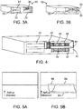
- FIG 3B is another form of simplified system 32 which includes air duct 20 on electronic device 10. As is apparent the available airflow will enter all parts of grilles 31, 33, 35 and 37 in FIG. 3A . In FIG. 3B air flow will be concentrated by air duct 20 into grille 35.
- FIG. 5A the airflow through electronic device 10, without an air duct, is generally evenly distributed throughout interior of electronic device 10, even in areas or portions which are blank or devoid of any heat generating component, such as a CPU or GPU.
- FIG. 5B illustrates the concentration and direction of incoming air flow 52 into a concentrated air flow area 54. If a heat generating component (not shown) were positioned downstream of air flow 54, it would benefit from the concentrated air flow 54. Additionally, area 56 is essentially devoid of a cooling stream of air flow. A blank portion or a portion devoid of a heat generating component could therefore be arranged in this section of electronic device 10 and none of the available air flow would be wasted in cooling this portion of electronic device 10.
- FIG. 4 is illustrative of another form of air duct 40 according to the present disclosure arranged on an electronic device 10.
- Air duct 40 has self-sustaining reticulated areas 42, 44 on the left side and bottom portions of duct 40, as illustrated in FIG. 4 respectively.
- the reticulated area 42 can be initially formed in air duct 40 upon formation of air duct 40, or may be post-formed therein by any suitable mechanical action, such as punching, drilling, broaching, and similar mechanical shaping methods.
- the reticulated area 44 can be made in a manner similar to or different from the manner in which reticulated area 42 is made.
- area 42 may be initially formed during formation of air duct 40 and reticulated area 44 may be post formed, or vice-versa.
- the self-sustaining reticulated areas 42 and 44 serve the same purpose by permitting additional air to enter the air duct 40, and then introducing that air into the interior of electronic device 10. This is especially useful where the interior of electronic device 10 is blank or devoid of heat generating components downstream of grille 31. The interior of electronic device 10 would thus not benefit from airflow through grille 31, but would benefit by additional air flow through self-sustaining reticulated portion 42 of air duct 40. The same would be true if the area behind grille 37 is blank or devoid of heat generating components, whereas additional air flow through reticulated area 44 would beneficially increase the air flow through air duct 40.
- elements 46 and 48 can represent the input openings of internal ducts (not shown) within electronic device 10. By preferentially introducing the air flow into elements 46 and 48, the air flow to certain portions of the interior of electronic device 10 can be controlled.
- the air duct of the embodiments may be attached to the flat bezel or electronic device 10 by any adhesive or mechanical fasteners, such as but not limited to, clips, screws, rivets, or other mechanical, or other chemical mechanisms.
- adhesive double-sided tape Examples of adhesive double-sided tape; pre-applied contact adhesive which is covered by a temporary, peelable, protective strip; fresh quick setting glue, etc.
- the mechanical fasteners, including screws, clips, or rivets can be formed of iron or its alloys; aluminum or its alloys; copper or its alloys, including brass; or polymeric materials such as nylon 6, nylon 66, fluorinated polymers, ceramics, and other materials used for fasteners.
- Other fasteners include hook and loop fasteners.
- the air duct itself may be integrally formed with one or more fastening devices, which may be the same or different from the group comprising hooks, clamps, pincers, grapnels, etc.
- the air duct may also be made to be slightly compressible, so as to be retained by the electronic device through a friction fit upon release of a compressive force on the air duct.
- Other manners of combining the air duct of the present disclosure with existing grilles on electronic devices, such as electronic device 10, will be apparent to those skilled in the art without the exercise of invention.
- the air duct can have different shapes, including less or more than four sides, or no sides, such as elliptical, ovate, circular, or another curved shape, or an opening offset from a central position, without departing from the teachings of this disclosure.
Landscapes
- Engineering & Computer Science (AREA)
- Microelectronics & Electronic Packaging (AREA)
- Physics & Mathematics (AREA)
- Thermal Sciences (AREA)
- General Engineering & Computer Science (AREA)
- Computer Hardware Design (AREA)
- Theoretical Computer Science (AREA)
- Human Computer Interaction (AREA)
- General Physics & Mathematics (AREA)
- Cooling Or The Like Of Electrical Apparatus (AREA)
Abstract
Description
- The present disclosure provides air ducts for the purpose of guiding air flow introduction to servers or other electronic equipment, but without the need for increasing impedance of the air flow, or increase in power necessary to cool the server or electronic equipment.
- Conventional systems for cooling electronic equipment, such as servers, switches, and storage systems, have a flat front bezel (panel) with several grilles for air flow as shown in
FIG. 1 (Prior Art). With a flat front bezel, the restricted entry of air as its passes through the front panel is like a sudden contraction flow, which can cause pressure drop due to minor loss. This effect will result in either a lower flow of incoming (cooling) airflow into the system, or the requirement for additional power for operating the air mover in the system. - In some fields of utilization, a heat generating component is populated immediately behind a specific part of the grille. Therefore, the grille requires a greater air flow rate to cool the heat generated by that component, in comparison to other parts of the electronic device which are blank (without any components or with no heat generating components). The traditional solution is to reduce the openings in the grille in front of the blank portions, with the intention of focusing more airflow though the grille immediately in front of the heat-generating component. However, this solution will cause higher system impedance which leads to additional air mover power consumption.
- Adding an additional air duct to the front panel could help in assisting the focus of air delivery to a specified portion of the electronic component, or to a specific heat generating component within the electronic component. The profile of any such air duct should be designed such that the duct could smoothen the air inlet flow to reduce the pressure drop, and increase air flow rate of a specific grille with lower air mover power consumption.
- In order to overcome the problems associated with the prior art flat front panel and grille system, the present inventors have provided, in a first embodiment, an air duct having a curved surface, with the intention of not only smoothing out the airflow through the duct, but also to provide a guide for the airflow to a desired specific portion of the front panel.
- According to another embodiment of the present disclosure, the air duct could be placed on a portion of the existing front panels of electronic equipment, so as to focus the air flow on a heat generating components within the electronic equipment and/or to prevent air flow to portions of the electronic equipment which are blank or devoid of heat generating components.
- In a still further embodiment of the present disclosure, the air duct itself may be provided with additional opening within portions of the walls of the air duct, to admit additional air flow into the air duct to provide greater air cooling effect or increased airflow through the air duct.
- This and other embodiments of the disclosure will be better understood when read in conjunction with the detailed description and the appended drawings. Particular and preferred aspects of the present invention are set out in the accompanying independent and dependent claims. Features of the dependent claims may be combined with features of the independent claims as appropriate, and in combinations other than those explicitly set out in the claims.
- The present invention will be described further, by way of example only, with reference to embodiments thereof as illustrated in the accompanying drawings, in which:
-
FIG. 1 (Prior Art) is a schematic representation of an existing front panel of an electronic component according to the prior art, having several grilles to permit air flow through the grilles. -
FIG. 2 is a schematic representation of an air duct according to one embodiment. -
FIG. 3A is a simplified system for air modeling wherein a flat panel with grilles is illustrated. -
FIG. 3B is a simplified system for air modeling wherein a flat panel with grilles similar toFIG. 3A is illustrated, but including an air duct according to an embodiment of the disclosure. -
FIG. 4 is a schematic representation of another embodiment of an air duct in combination with flat panel with grilles is illustrated. -
FIG. 5A is an airflow contour comparison without an air duct. -
FIG. 5B is an airflow contour comparison with an air duct according to an embodiment of the disclosure. - The present invention is described with reference to the attached figures, wherein like reference numerals are used throughout the figures to designate similar or equivalent elements. The figures are not drawn to scale, and they are provided merely to illustrate the instant invention. Several aspects of the invention are described below with reference to example applications for illustration. It should be understood that numerous specific details, relationships, and methods are set forth to provide a full understanding of the invention. One having ordinary skill in the relevant art, however, will readily recognize that the invention can be practiced without one or more of the specific details or with other methods. In other instances, well-known structures or operations are not shown in detail to avoid obscuring the invention. The present invention is not limited by the illustrated ordering of acts or events, as some acts may occur in different orders and/or concurrently with other acts or events. Furthermore, not all illustrated acts or events are required to implement a methodology in accordance with the present invention.
-
FIG. 1 is illustration of the current state of the art of anelectronic device 10 comprising aflat front bezel 9 havinggrilles 11. 12, 13, and 14 therein. The grilles permit cooling air flow to enter theelectronic device 10 for purposes of cooling heat generating components (not shown) contained withinelectronic device 10. Theelectronic device 10 can be selected from a server, a switch, and other electronic devices. Arranged withinelectronic device 10 could be one or more heat generating components, such as a central processing unit ("CPU"), a graphics processing unit ("GPU"), and similar components. While the positioning, arrangement, or layout of these heat generating components is not part of this disclosure, the positioning of the air duct 20 (FIG. 2 ) assists in directing the air flow to cool these heat generating components, while avoiding air flow to sections of theelectronic device 10 which are blank (or do not contain a heat generating component). In this manner,air duct 20 directs the air flow to the position in which it is needed withinelectronic device 10. -
FIG. 2 illustratesair duct 20.Air duct 20 could be manufactured out of several suitable materials, including metal, plastics (polymers), composite materials and combinations thereof. Plastics and composites are preferred because they are lightweight and the polymers which form the plastics could contain fillers that make the air duct static free. Suitable fillers include carbon, graphite, metal flakes, or metal powders and other materials that will dissipate any electrical charges created by static electricity. Composites can include a polymer and some type of reinforcing material, such as filaments, natural, synthetic or glass fibers, batts, woven and nonwoven fabrics, rovings, tapes, metal wires, screens, or reticulated forms of metal, metalized coatings and films, and other reinforcing components. At least one of the reinforcing materials can include a static electricity dissipating material, such as carbon, graphite, or metal fibers. Alternatively, a non-static dissipating material may be used, provided that it also comprising the fillers or other materials that will dissipate static electricity. An air duct without a static electricity dissipating material can also be used, but the attraction of dust or other air entrained particulates within the airflow may be attracted to the air duct. A separate air filtering device can then be used in combination with the air flow to filter out entrained particulate within the air flow. A metal framework or reinforcement covered in a polymer coating could also be used to form the air duct of the disclosure. The air duct can be provided with slightly curvedinterior walls air duct 20. -
FIG. 3A is one form ofsimplified system 30 used for thermal modeling of air flow intoelectronic device 10.FIG 3B is another form ofsimplified system 32 which includesair duct 20 onelectronic device 10. As is apparent the available airflow will enter all parts ofgrilles FIG. 3A . InFIG. 3B air flow will be concentrated byair duct 20 intogrille 35. - As can be seen in
FIG. 5A , the airflow throughelectronic device 10, without an air duct, is generally evenly distributed throughout interior ofelectronic device 10, even in areas or portions which are blank or devoid of any heat generating component, such as a CPU or GPU. On the other hand,FIG. 5B illustrates the concentration and direction ofincoming air flow 52 into a concentratedair flow area 54. If a heat generating component (not shown) were positioned downstream ofair flow 54, it would benefit from theconcentrated air flow 54. Additionally,area 56 is essentially devoid of a cooling stream of air flow. A blank portion or a portion devoid of a heat generating component could therefore be arranged in this section ofelectronic device 10 and none of the available air flow would be wasted in cooling this portion ofelectronic device 10. It is also within the scope of this disclosure to position one or more of theair ducts 20 so as to increase the efficiency of cooling of existingelectronic devices 10 having a prearranged arrangement of components therein. From the simulation result ofFIG. 5B , as compared toFIG. 5A , airflow contour for the case with air duct is clearly much smoother than the result without an air duct. Measurements show about a 7.6% improvement in airflow rate though the portion of the electronic device with the air duct, while the overall system impedance/pressure drop is also improved by about 7.1%. These improvements are achieved without increasing the power to the air mover, resulting in unexpected improvement in cooling effect. One of ordinary skill in the art, to which this disclosure is directed, would be able to arrange one or more air ducts to increase the efficiency of cooling of components withinelectronic device 10, but without increasing the power input of any air mover used to create an airflow forelectronic device 10. -
FIG. 4 is illustrative of another form ofair duct 40 according to the present disclosure arranged on anelectronic device 10.Air duct 40 has self-sustainingreticulated areas duct 40, as illustrated inFIG. 4 respectively. Thereticulated area 42 can be initially formed inair duct 40 upon formation ofair duct 40, or may be post-formed therein by any suitable mechanical action, such as punching, drilling, broaching, and similar mechanical shaping methods. Similarly, thereticulated area 44 can be made in a manner similar to or different from the manner in which reticulatedarea 42 is made. For example,area 42 may be initially formed during formation ofair duct 40 andreticulated area 44 may be post formed, or vice-versa. The self-sustainingreticulated areas air duct 40, and then introducing that air into the interior ofelectronic device 10. This is especially useful where the interior ofelectronic device 10 is blank or devoid of heat generating components downstream ofgrille 31. The interior ofelectronic device 10 would thus not benefit from airflow throughgrille 31, but would benefit by additional air flow through self-sustainingreticulated portion 42 ofair duct 40. The same would be true if the area behindgrille 37 is blank or devoid of heat generating components, whereas additional air flow throughreticulated area 44 would beneficially increase the air flow throughair duct 40. - The foregoing description of different embodiments of air ducts can also be used in combination with internal baffling, or ducts within
electronic device 10, to beneficially increase the air flow to certain interior portions ofelectronic device 10. For example,elements electronic device 10. By preferentially introducing the air flow intoelements electronic device 10 can be controlled. - The air duct of the embodiments may be attached to the flat bezel or
electronic device 10 by any adhesive or mechanical fasteners, such as but not limited to, clips, screws, rivets, or other mechanical, or other chemical mechanisms. Examples of adhesive double-sided tape; pre-applied contact adhesive which is covered by a temporary, peelable, protective strip; fresh quick setting glue, etc. The mechanical fasteners, including screws, clips, or rivets can be formed of iron or its alloys; aluminum or its alloys; copper or its alloys, including brass; or polymeric materials such as nylon 6, nylon 66, fluorinated polymers, ceramics, and other materials used for fasteners. Other fasteners include hook and loop fasteners. The air duct itself may be integrally formed with one or more fastening devices, which may be the same or different from the group comprising hooks, clamps, pincers, grapnels, etc. The air duct may also be made to be slightly compressible, so as to be retained by the electronic device through a friction fit upon release of a compressive force on the air duct. Other manners of combining the air duct of the present disclosure with existing grilles on electronic devices, such aselectronic device 10, will be apparent to those skilled in the art without the exercise of invention. - While we have illustrated the air duct as a quadrilateral-sided configuration with a central opening, it is to be understood that the air duct can have different shapes, including less or more than four sides, or no sides, such as elliptical, ovate, circular, or another curved shape, or an opening offset from a central position, without departing from the teachings of this disclosure.
- It is to be expressly understood that the various embodiments described herein are exemplary only, and not limiting, as those skilled in the art to which this application is directed, will, upon reading this disclosure, envision other modifications and embodiments to implement the teaching of this disclosure without the exercise of invention.
Although particular embodiments have been described herein, it will be appreciated that the invention is not limited thereto and that many modifications and additions thereto may be made within the scope of the invention. For example, various combinations of the features of the following dependent claims can be made with the features of the independent claims without departing from the scope of the present invention.
Claims (12)
- An air duct (20, 40) comprising metal, plastics, composite materials, and combinations thereof, the air duct (20, 40) being characterized by further comprising at least one element (46, 48) integral with the air duct (20, 40), wherein the at least one element (46, 48) permits attachment of the air duct (20, 40) to a grille (31, 33, 35, 37) of an electronic device (10).
- The air duct (20, 40) of claim 1, characterized in that the electronic device (10) is a server having at least one heat generating component therein, and at least one blank space (56) devoid of the heat generating component.
- The air duct (20, 40) of claim 1 or claim 2, characterized by further comprising at least one static electricity dissipating element.
- The air duct (20, 40) of any of claims 1-3, characterized in that the air duct (20, 40) is sized and shaped to achieve at least a 7% improvement in airflow rate, and an overall system impedance/pressure drop of at least 7% without increasing power to an air mover.
- The air duct (20, 40) of any of claims 1-4, characterized in that the air duct (20, 40) is quadrilateral in external shape.
- The air duct (20, 40) of claim 5, characterized in that the air duct (20, 40) has more than one portion of the quadrilateral shape that is reticulated.
- A combination comprises the air duct (20, 40) of any one of claims 1-6 and an electronic device (10), the combination being characterized by the air duct (20, 40) being attachable to an external portion of the electronic device (10); the air duct (20, 40) comprising a shape to increase the flow of air to a specific portion (54) of an interior of the electronic device (10).
- The combination of claim 7, characterized in that the electronic device (10) further comprises heat generating components in the interior thereof; and the air duct (20, 40) increases the flow of air towards the heat generating components.
- The combination of claim 8, characterized in that the electronic device (10) also comprises blank portions (56) in the interior thereof, and the air duct (20, 40) decreases the flow of air towards the blank portions (56).
- The combination of any of claims 7-9, characterized in that the air duct (20, 40) has an opening centrally located.
- The combination of any of claims 7-10, characterized in that the air duct (20, 40) is combined with the electronic device (10) through at least one of adhesive and mechanical fasteners.
- The combination of any of claims 7-11, characterized by the electronic device (10) comprising a flat bezel (9) with grilles (31, 33, 35, 37, 42, 44, 46,48), the air duct (20, 40) being attachable to at least one of the grilles (35, 46, 48); the air duct(20, 40) comprising a shape to increase the flow of air to a specific portion (54) of an interior of the electronic device (10).
Applications Claiming Priority (2)
| Application Number | Priority Date | Filing Date | Title |
|---|---|---|---|
| US201862616641P | 2018-01-12 | 2018-01-12 | |
| US15/939,690 US11102909B2 (en) | 2018-01-12 | 2018-03-29 | Front panel air duct |
Publications (2)
| Publication Number | Publication Date |
|---|---|
| EP3512320A1 true EP3512320A1 (en) | 2019-07-17 |
| EP3512320B1 EP3512320B1 (en) | 2024-02-21 |
Family
ID=65003144
Family Applications (1)
| Application Number | Title | Priority Date | Filing Date |
|---|---|---|---|
| EP18215642.2A Active EP3512320B1 (en) | 2018-01-12 | 2018-12-21 | Front panel air duct |
Country Status (5)
| Country | Link |
|---|---|
| US (1) | US11102909B2 (en) |
| EP (1) | EP3512320B1 (en) |
| JP (1) | JP6744908B2 (en) |
| CN (1) | CN110035635B (en) |
| TW (1) | TWI690258B (en) |
Citations (3)
| Publication number | Priority date | Publication date | Assignee | Title |
|---|---|---|---|---|
| US6552898B1 (en) * | 1998-01-29 | 2003-04-22 | Intel Corporation | Fan duct module |
| US20130141863A1 (en) * | 2011-12-05 | 2013-06-06 | Peter G. Ross | Partial-Width Rack-Mounted Computing Devices |
| US9622387B1 (en) * | 2010-03-31 | 2017-04-11 | Amazon Technologies, Inc. | Rack-mounted air directing device with scoop |
Family Cites Families (17)
| Publication number | Priority date | Publication date | Assignee | Title |
|---|---|---|---|---|
| US3359883A (en) * | 1965-08-26 | 1967-12-26 | Charles F Wirth | Heating duct attachment |
| JPS6228491U (en) * | 1985-08-01 | 1987-02-20 | ||
| GB2358243B (en) * | 1999-11-24 | 2004-03-31 | 3Com Corp | Thermally conductive moulded heat sink |
| JP4896359B2 (en) | 2003-01-28 | 2012-03-14 | 富士通株式会社 | Electronic equipment |
| US20050276017A1 (en) | 2004-06-10 | 2005-12-15 | Farid Aziz | Common plenum and air intake airflow management for telecom equipment |
| JP3128289U (en) | 2006-09-22 | 2007-01-11 | ゴウ、ティエンユー | PTC heat generating module having a wind guide plate |
| PL1970482T3 (en) * | 2007-03-13 | 2011-01-31 | Electrolux Home Products Corp Nv | Home laundry drier |
| US7839635B2 (en) | 2007-05-17 | 2010-11-23 | Chatsworth Products, Inc. | Exhaust air duct with adjustable filler panel assemblies |
| US8009430B2 (en) * | 2007-05-17 | 2011-08-30 | International Business Machines Corporation | Techniques for data center cooling |
| US7817430B2 (en) * | 2007-06-12 | 2010-10-19 | Hewlett-Packard Development Company, L.P. | Airflow adjustment in an electronic module enclosure |
| JP2009009961A (en) * | 2007-06-26 | 2009-01-15 | Tamachi Denki Kk | Cooling unit |
| JPWO2009116647A1 (en) * | 2008-03-21 | 2011-07-21 | 日本電気株式会社 | Fan unit and electronic device including the same |
| JP2012521657A (en) | 2009-03-25 | 2012-09-13 | ヒューレット−パッカード デベロップメント カンパニー エル.ピー. | Grid heat sink |
| CN101762964B (en) * | 2010-01-27 | 2011-07-13 | 苏州佳世达光电有限公司 | Projector |
| JP5756210B2 (en) | 2014-05-19 | 2015-07-29 | 日本電信電話株式会社 | Airflow optimization means when mounting ICT equipment in cabinet |
| CN105283028B (en) * | 2014-06-26 | 2019-07-09 | 中兴通讯股份有限公司 | A kind of denoising device and method |
| CN107054673A (en) * | 2017-06-29 | 2017-08-18 | 中国人民解放军国防科学技术大学 | It is a kind of to synthesize dual-jet driver and hypersonic flow flowing control method from maintenance |
-
2018
- 2018-03-29 US US15/939,690 patent/US11102909B2/en active Active
- 2018-08-08 TW TW107127679A patent/TWI690258B/en active
- 2018-08-29 CN CN201810994047.2A patent/CN110035635B/en active Active
- 2018-12-21 EP EP18215642.2A patent/EP3512320B1/en active Active
- 2018-12-28 JP JP2018247062A patent/JP6744908B2/en active Active
Patent Citations (3)
| Publication number | Priority date | Publication date | Assignee | Title |
|---|---|---|---|---|
| US6552898B1 (en) * | 1998-01-29 | 2003-04-22 | Intel Corporation | Fan duct module |
| US9622387B1 (en) * | 2010-03-31 | 2017-04-11 | Amazon Technologies, Inc. | Rack-mounted air directing device with scoop |
| US20130141863A1 (en) * | 2011-12-05 | 2013-06-06 | Peter G. Ross | Partial-Width Rack-Mounted Computing Devices |
Also Published As
| Publication number | Publication date |
|---|---|
| CN110035635B (en) | 2020-12-04 |
| JP2019125365A (en) | 2019-07-25 |
| CN110035635A (en) | 2019-07-19 |
| EP3512320B1 (en) | 2024-02-21 |
| TWI690258B (en) | 2020-04-01 |
| US20190223317A1 (en) | 2019-07-18 |
| TW201931984A (en) | 2019-08-01 |
| US11102909B2 (en) | 2021-08-24 |
| JP6744908B2 (en) | 2020-08-19 |
Similar Documents
| Publication | Publication Date | Title |
|---|---|---|
| EP2789518B9 (en) | Cooling device for under-floor device for vehicle | |
| US10412855B2 (en) | Air deflection system | |
| CN108767766B (en) | Wiring device of household appliance and air conditioner with same | |
| CN206648183U (en) | Mobile air conditioner | |
| GB2358243A (en) | Cooling apparatus for electrical equipment | |
| JP5139370B2 (en) | control panel | |
| CN105276779A (en) | Connecting Wire Fixing Device, Electric Component Box Using This Connecting Wire Fixing Device, And Indoor Unit Of Air-Conditioning Apparatus | |
| EP3512320B1 (en) | Front panel air duct | |
| US9506375B2 (en) | Fan guard | |
| TW201309994A (en) | Airflow guiding device | |
| CN211667910U (en) | An air conditioner purification assembly and an air conditioner assembly | |
| CN105890051A (en) | Wall-mounted air-conditioner indoor machine and wall-mounted air-conditioner | |
| CN205878512U (en) | Grid assembly and interior machine of air conditioning of machine in air conditioning | |
| CN108278677B (en) | Air duct assembly of air conditioner indoor unit, air conditioner indoor unit and air conditioner | |
| CN214841191U (en) | Air conditioner indoor unit and air conditioner | |
| CN205579793U (en) | Air conditioner outdoor unit and air conditioner | |
| WO2024082384A1 (en) | Indoor unit of wall-mounted air conditioner | |
| CN211177124U (en) | Air conditioner indoor unit and air conditioner | |
| TW201141364A (en) | Heat dissipating system for server | |
| CN211424647U (en) | Air duct component of air conditioner and air conditioner | |
| CN207488911U (en) | A kind of heat-radiating chassis for computer | |
| CN212057526U (en) | Electric heating module, air purification module and air conditioner | |
| CN210128459U (en) | Dehumidifier | |
| CN213818724U (en) | An industrial computer that is easy to move and dissipate heat | |
| CN213806302U (en) | Detachable sound-absorbing aluminum plate assembly |
Legal Events
| Date | Code | Title | Description |
|---|---|---|---|
| PUAI | Public reference made under article 153(3) epc to a published international application that has entered the european phase |
Free format text: ORIGINAL CODE: 0009012 |
|
| STAA | Information on the status of an ep patent application or granted ep patent |
Free format text: STATUS: THE APPLICATION HAS BEEN PUBLISHED |
|
| AK | Designated contracting states |
Kind code of ref document: A1 Designated state(s): AL AT BE BG CH CY CZ DE DK EE ES FI FR GB GR HR HU IE IS IT LI LT LU LV MC MK MT NL NO PL PT RO RS SE SI SK SM TR |
|
| AX | Request for extension of the european patent |
Extension state: BA ME |
|
| STAA | Information on the status of an ep patent application or granted ep patent |
Free format text: STATUS: REQUEST FOR EXAMINATION WAS MADE |
|
| 17P | Request for examination filed |
Effective date: 20200117 |
|
| RBV | Designated contracting states (corrected) |
Designated state(s): AL AT BE BG CH CY CZ DE DK EE ES FI FR GB GR HR HU IE IS IT LI LT LU LV MC MK MT NL NO PL PT RO RS SE SI SK SM TR |
|
| STAA | Information on the status of an ep patent application or granted ep patent |
Free format text: STATUS: EXAMINATION IS IN PROGRESS |
|
| 17Q | First examination report despatched |
Effective date: 20220104 |
|
| GRAP | Despatch of communication of intention to grant a patent |
Free format text: ORIGINAL CODE: EPIDOSNIGR1 |
|
| STAA | Information on the status of an ep patent application or granted ep patent |
Free format text: STATUS: GRANT OF PATENT IS INTENDED |
|
| INTG | Intention to grant announced |
Effective date: 20230921 |
|
| GRAS | Grant fee paid |
Free format text: ORIGINAL CODE: EPIDOSNIGR3 |
|
| GRAA | (expected) grant |
Free format text: ORIGINAL CODE: 0009210 |
|
| STAA | Information on the status of an ep patent application or granted ep patent |
Free format text: STATUS: THE PATENT HAS BEEN GRANTED |
|
| AK | Designated contracting states |
Kind code of ref document: B1 Designated state(s): AL AT BE BG CH CY CZ DE DK EE ES FI FR GB GR HR HU IE IS IT LI LT LU LV MC MK MT NL NO PL PT RO RS SE SI SK SM TR |
|
| REG | Reference to a national code |
Ref country code: GB Ref legal event code: FG4D |
|
| REG | Reference to a national code |
Ref country code: CH Ref legal event code: EP |
|
| REG | Reference to a national code |
Ref country code: IE Ref legal event code: FG4D |
|
| REG | Reference to a national code |
Ref country code: DE Ref legal event code: R096 Ref document number: 602018065474 Country of ref document: DE |
|
| REG | Reference to a national code |
Ref country code: LT Ref legal event code: MG9D |
|
| REG | Reference to a national code |
Ref country code: NL Ref legal event code: MP Effective date: 20240221 |
|
| PG25 | Lapsed in a contracting state [announced via postgrant information from national office to epo] |
Ref country code: IS Free format text: LAPSE BECAUSE OF FAILURE TO SUBMIT A TRANSLATION OF THE DESCRIPTION OR TO PAY THE FEE WITHIN THE PRESCRIBED TIME-LIMIT Effective date: 20240621 |
|
| PG25 | Lapsed in a contracting state [announced via postgrant information from national office to epo] |
Ref country code: LT Free format text: LAPSE BECAUSE OF FAILURE TO SUBMIT A TRANSLATION OF THE DESCRIPTION OR TO PAY THE FEE WITHIN THE PRESCRIBED TIME-LIMIT Effective date: 20240221 |
|
| PG25 | Lapsed in a contracting state [announced via postgrant information from national office to epo] |
Ref country code: GR Free format text: LAPSE BECAUSE OF FAILURE TO SUBMIT A TRANSLATION OF THE DESCRIPTION OR TO PAY THE FEE WITHIN THE PRESCRIBED TIME-LIMIT Effective date: 20240522 |
|
| REG | Reference to a national code |
Ref country code: AT Ref legal event code: MK05 Ref document number: 1660249 Country of ref document: AT Kind code of ref document: T Effective date: 20240221 |
|
| PG25 | Lapsed in a contracting state [announced via postgrant information from national office to epo] |
Ref country code: HR Free format text: LAPSE BECAUSE OF FAILURE TO SUBMIT A TRANSLATION OF THE DESCRIPTION OR TO PAY THE FEE WITHIN THE PRESCRIBED TIME-LIMIT Effective date: 20240221 Ref country code: NL Free format text: LAPSE BECAUSE OF FAILURE TO SUBMIT A TRANSLATION OF THE DESCRIPTION OR TO PAY THE FEE WITHIN THE PRESCRIBED TIME-LIMIT Effective date: 20240221 Ref country code: RS Free format text: LAPSE BECAUSE OF FAILURE TO SUBMIT A TRANSLATION OF THE DESCRIPTION OR TO PAY THE FEE WITHIN THE PRESCRIBED TIME-LIMIT Effective date: 20240521 |
|
| PG25 | Lapsed in a contracting state [announced via postgrant information from national office to epo] |
Ref country code: ES Free format text: LAPSE BECAUSE OF FAILURE TO SUBMIT A TRANSLATION OF THE DESCRIPTION OR TO PAY THE FEE WITHIN THE PRESCRIBED TIME-LIMIT Effective date: 20240221 |
|
| PG25 | Lapsed in a contracting state [announced via postgrant information from national office to epo] |
Ref country code: AT Free format text: LAPSE BECAUSE OF FAILURE TO SUBMIT A TRANSLATION OF THE DESCRIPTION OR TO PAY THE FEE WITHIN THE PRESCRIBED TIME-LIMIT Effective date: 20240221 |
|
| PG25 | Lapsed in a contracting state [announced via postgrant information from national office to epo] |
Ref country code: RS Free format text: LAPSE BECAUSE OF FAILURE TO SUBMIT A TRANSLATION OF THE DESCRIPTION OR TO PAY THE FEE WITHIN THE PRESCRIBED TIME-LIMIT Effective date: 20240521 Ref country code: NO Free format text: LAPSE BECAUSE OF FAILURE TO SUBMIT A TRANSLATION OF THE DESCRIPTION OR TO PAY THE FEE WITHIN THE PRESCRIBED TIME-LIMIT Effective date: 20240521 Ref country code: NL Free format text: LAPSE BECAUSE OF FAILURE TO SUBMIT A TRANSLATION OF THE DESCRIPTION OR TO PAY THE FEE WITHIN THE PRESCRIBED TIME-LIMIT Effective date: 20240221 Ref country code: LT Free format text: LAPSE BECAUSE OF FAILURE TO SUBMIT A TRANSLATION OF THE DESCRIPTION OR TO PAY THE FEE WITHIN THE PRESCRIBED TIME-LIMIT Effective date: 20240221 Ref country code: IS Free format text: LAPSE BECAUSE OF FAILURE TO SUBMIT A TRANSLATION OF THE DESCRIPTION OR TO PAY THE FEE WITHIN THE PRESCRIBED TIME-LIMIT Effective date: 20240621 Ref country code: HR Free format text: LAPSE BECAUSE OF FAILURE TO SUBMIT A TRANSLATION OF THE DESCRIPTION OR TO PAY THE FEE WITHIN THE PRESCRIBED TIME-LIMIT Effective date: 20240221 Ref country code: GR Free format text: LAPSE BECAUSE OF FAILURE TO SUBMIT A TRANSLATION OF THE DESCRIPTION OR TO PAY THE FEE WITHIN THE PRESCRIBED TIME-LIMIT Effective date: 20240522 Ref country code: FI Free format text: LAPSE BECAUSE OF FAILURE TO SUBMIT A TRANSLATION OF THE DESCRIPTION OR TO PAY THE FEE WITHIN THE PRESCRIBED TIME-LIMIT Effective date: 20240221 Ref country code: ES Free format text: LAPSE BECAUSE OF FAILURE TO SUBMIT A TRANSLATION OF THE DESCRIPTION OR TO PAY THE FEE WITHIN THE PRESCRIBED TIME-LIMIT Effective date: 20240221 Ref country code: BG Free format text: LAPSE BECAUSE OF FAILURE TO SUBMIT A TRANSLATION OF THE DESCRIPTION OR TO PAY THE FEE WITHIN THE PRESCRIBED TIME-LIMIT Effective date: 20240221 Ref country code: AT Free format text: LAPSE BECAUSE OF FAILURE TO SUBMIT A TRANSLATION OF THE DESCRIPTION OR TO PAY THE FEE WITHIN THE PRESCRIBED TIME-LIMIT Effective date: 20240221 |
|
| PG25 | Lapsed in a contracting state [announced via postgrant information from national office to epo] |
Ref country code: PL Free format text: LAPSE BECAUSE OF FAILURE TO SUBMIT A TRANSLATION OF THE DESCRIPTION OR TO PAY THE FEE WITHIN THE PRESCRIBED TIME-LIMIT Effective date: 20240221 Ref country code: PT Free format text: LAPSE BECAUSE OF FAILURE TO SUBMIT A TRANSLATION OF THE DESCRIPTION OR TO PAY THE FEE WITHIN THE PRESCRIBED TIME-LIMIT Effective date: 20240621 |
|
| PG25 | Lapsed in a contracting state [announced via postgrant information from national office to epo] |
Ref country code: SE Free format text: LAPSE BECAUSE OF FAILURE TO SUBMIT A TRANSLATION OF THE DESCRIPTION OR TO PAY THE FEE WITHIN THE PRESCRIBED TIME-LIMIT Effective date: 20240221 Ref country code: PT Free format text: LAPSE BECAUSE OF FAILURE TO SUBMIT A TRANSLATION OF THE DESCRIPTION OR TO PAY THE FEE WITHIN THE PRESCRIBED TIME-LIMIT Effective date: 20240621 Ref country code: PL Free format text: LAPSE BECAUSE OF FAILURE TO SUBMIT A TRANSLATION OF THE DESCRIPTION OR TO PAY THE FEE WITHIN THE PRESCRIBED TIME-LIMIT Effective date: 20240221 Ref country code: LV Free format text: LAPSE BECAUSE OF FAILURE TO SUBMIT A TRANSLATION OF THE DESCRIPTION OR TO PAY THE FEE WITHIN THE PRESCRIBED TIME-LIMIT Effective date: 20240221 |
|
| PG25 | Lapsed in a contracting state [announced via postgrant information from national office to epo] |
Ref country code: DK Free format text: LAPSE BECAUSE OF FAILURE TO SUBMIT A TRANSLATION OF THE DESCRIPTION OR TO PAY THE FEE WITHIN THE PRESCRIBED TIME-LIMIT Effective date: 20240221 |
|
| PG25 | Lapsed in a contracting state [announced via postgrant information from national office to epo] |
Ref country code: SM Free format text: LAPSE BECAUSE OF FAILURE TO SUBMIT A TRANSLATION OF THE DESCRIPTION OR TO PAY THE FEE WITHIN THE PRESCRIBED TIME-LIMIT Effective date: 20240221 |
|
| PG25 | Lapsed in a contracting state [announced via postgrant information from national office to epo] |
Ref country code: CZ Free format text: LAPSE BECAUSE OF FAILURE TO SUBMIT A TRANSLATION OF THE DESCRIPTION OR TO PAY THE FEE WITHIN THE PRESCRIBED TIME-LIMIT Effective date: 20240221 Ref country code: EE Free format text: LAPSE BECAUSE OF FAILURE TO SUBMIT A TRANSLATION OF THE DESCRIPTION OR TO PAY THE FEE WITHIN THE PRESCRIBED TIME-LIMIT Effective date: 20240221 |
|
| PG25 | Lapsed in a contracting state [announced via postgrant information from national office to epo] |
Ref country code: SK Free format text: LAPSE BECAUSE OF FAILURE TO SUBMIT A TRANSLATION OF THE DESCRIPTION OR TO PAY THE FEE WITHIN THE PRESCRIBED TIME-LIMIT Effective date: 20240221 |
|
| PG25 | Lapsed in a contracting state [announced via postgrant information from national office to epo] |
Ref country code: SM Free format text: LAPSE BECAUSE OF FAILURE TO SUBMIT A TRANSLATION OF THE DESCRIPTION OR TO PAY THE FEE WITHIN THE PRESCRIBED TIME-LIMIT Effective date: 20240221 Ref country code: SK Free format text: LAPSE BECAUSE OF FAILURE TO SUBMIT A TRANSLATION OF THE DESCRIPTION OR TO PAY THE FEE WITHIN THE PRESCRIBED TIME-LIMIT Effective date: 20240221 Ref country code: RO Free format text: LAPSE BECAUSE OF FAILURE TO SUBMIT A TRANSLATION OF THE DESCRIPTION OR TO PAY THE FEE WITHIN THE PRESCRIBED TIME-LIMIT Effective date: 20240221 Ref country code: EE Free format text: LAPSE BECAUSE OF FAILURE TO SUBMIT A TRANSLATION OF THE DESCRIPTION OR TO PAY THE FEE WITHIN THE PRESCRIBED TIME-LIMIT Effective date: 20240221 Ref country code: DK Free format text: LAPSE BECAUSE OF FAILURE TO SUBMIT A TRANSLATION OF THE DESCRIPTION OR TO PAY THE FEE WITHIN THE PRESCRIBED TIME-LIMIT Effective date: 20240221 Ref country code: CZ Free format text: LAPSE BECAUSE OF FAILURE TO SUBMIT A TRANSLATION OF THE DESCRIPTION OR TO PAY THE FEE WITHIN THE PRESCRIBED TIME-LIMIT Effective date: 20240221 |
|
| REG | Reference to a national code |
Ref country code: DE Ref legal event code: R097 Ref document number: 602018065474 Country of ref document: DE |
|
| PG25 | Lapsed in a contracting state [announced via postgrant information from national office to epo] |
Ref country code: IT Free format text: LAPSE BECAUSE OF FAILURE TO SUBMIT A TRANSLATION OF THE DESCRIPTION OR TO PAY THE FEE WITHIN THE PRESCRIBED TIME-LIMIT Effective date: 20240221 |
|
| PLBE | No opposition filed within time limit |
Free format text: ORIGINAL CODE: 0009261 |
|
| STAA | Information on the status of an ep patent application or granted ep patent |
Free format text: STATUS: NO OPPOSITION FILED WITHIN TIME LIMIT |
|
| PG25 | Lapsed in a contracting state [announced via postgrant information from national office to epo] |
Ref country code: IT Free format text: LAPSE BECAUSE OF FAILURE TO SUBMIT A TRANSLATION OF THE DESCRIPTION OR TO PAY THE FEE WITHIN THE PRESCRIBED TIME-LIMIT Effective date: 20240221 |
|
| 26N | No opposition filed |
Effective date: 20241122 |
|
| PG25 | Lapsed in a contracting state [announced via postgrant information from national office to epo] |
Ref country code: SI Free format text: LAPSE BECAUSE OF FAILURE TO SUBMIT A TRANSLATION OF THE DESCRIPTION OR TO PAY THE FEE WITHIN THE PRESCRIBED TIME-LIMIT Effective date: 20240221 |
|
| PG25 | Lapsed in a contracting state [announced via postgrant information from national office to epo] |
Ref country code: MC Free format text: LAPSE BECAUSE OF FAILURE TO SUBMIT A TRANSLATION OF THE DESCRIPTION OR TO PAY THE FEE WITHIN THE PRESCRIBED TIME-LIMIT Effective date: 20240221 |
|
| REG | Reference to a national code |
Ref country code: CH Ref legal event code: PL |
|
| PG25 | Lapsed in a contracting state [announced via postgrant information from national office to epo] |
Ref country code: LU Free format text: LAPSE BECAUSE OF NON-PAYMENT OF DUE FEES Effective date: 20241221 |
|
| REG | Reference to a national code |
Ref country code: BE Ref legal event code: MM Effective date: 20241231 |
|
| PG25 | Lapsed in a contracting state [announced via postgrant information from national office to epo] |
Ref country code: BE Free format text: LAPSE BECAUSE OF NON-PAYMENT OF DUE FEES Effective date: 20241231 |
|
| PG25 | Lapsed in a contracting state [announced via postgrant information from national office to epo] |
Ref country code: CH Free format text: LAPSE BECAUSE OF NON-PAYMENT OF DUE FEES Effective date: 20241231 |
|
| PG25 | Lapsed in a contracting state [announced via postgrant information from national office to epo] |
Ref country code: IE Free format text: LAPSE BECAUSE OF NON-PAYMENT OF DUE FEES Effective date: 20241221 |
|
| PGFP | Annual fee paid to national office [announced via postgrant information from national office to epo] |
Ref country code: DE Payment date: 20251028 Year of fee payment: 8 |
|
| PGFP | Annual fee paid to national office [announced via postgrant information from national office to epo] |
Ref country code: GB Payment date: 20251030 Year of fee payment: 8 |
|
| PGFP | Annual fee paid to national office [announced via postgrant information from national office to epo] |
Ref country code: FR Payment date: 20251023 Year of fee payment: 8 |
|
| PG25 | Lapsed in a contracting state [announced via postgrant information from national office to epo] |
Ref country code: CY Free format text: LAPSE BECAUSE OF FAILURE TO SUBMIT A TRANSLATION OF THE DESCRIPTION OR TO PAY THE FEE WITHIN THE PRESCRIBED TIME-LIMIT Effective date: 20240221 |