EP3512289A1 - Procédé de communication sans fil utilisant un accès de canal distribué amélioré et un terminal de communication sans fil utilisant ce dernier - Google Patents
Procédé de communication sans fil utilisant un accès de canal distribué amélioré et un terminal de communication sans fil utilisant ce dernier Download PDFInfo
- Publication number
- EP3512289A1 EP3512289A1 EP17849113.0A EP17849113A EP3512289A1 EP 3512289 A1 EP3512289 A1 EP 3512289A1 EP 17849113 A EP17849113 A EP 17849113A EP 3512289 A1 EP3512289 A1 EP 3512289A1
- Authority
- EP
- European Patent Office
- Prior art keywords
- wireless communication
- communication terminal
- parameter set
- timer
- trigger
- Prior art date
- Legal status (The legal status is an assumption and is not a legal conclusion. Google has not performed a legal analysis and makes no representation as to the accuracy of the status listed.)
- Granted
Links
- 238000004891 communication Methods 0.000 title claims abstract description 749
- 238000000034 method Methods 0.000 title claims description 72
- 238000012545 processing Methods 0.000 claims abstract description 6
- 230000005540 biological transmission Effects 0.000 claims description 168
- 230000004044 response Effects 0.000 claims description 74
- 108700026140 MAC combination Proteins 0.000 claims description 4
- 101100161473 Arabidopsis thaliana ABCB25 gene Proteins 0.000 description 33
- 101100096893 Mus musculus Sult2a1 gene Proteins 0.000 description 33
- 101150081243 STA1 gene Proteins 0.000 description 33
- ATRSAWXXYCBXLI-UHFFFAOYSA-N 1-(3-bromophenyl)propan-2-amine Chemical compound CC(N)CC1=CC=CC(Br)=C1 ATRSAWXXYCBXLI-UHFFFAOYSA-N 0.000 description 21
- 230000008859 change Effects 0.000 description 15
- 238000005516 engineering process Methods 0.000 description 15
- 230000009471 action Effects 0.000 description 11
- 230000001960 triggered effect Effects 0.000 description 11
- 238000010586 diagram Methods 0.000 description 7
- 230000004048 modification Effects 0.000 description 7
- 238000012986 modification Methods 0.000 description 7
- 102100029716 DnaJ homolog subfamily A member 3, mitochondrial Human genes 0.000 description 5
- 101000866012 Homo sapiens DnaJ homolog subfamily A member 3, mitochondrial Proteins 0.000 description 5
- 230000008569 process Effects 0.000 description 5
- 230000000694 effects Effects 0.000 description 4
- 239000000523 sample Substances 0.000 description 3
- 101001112162 Homo sapiens Kinetochore protein NDC80 homolog Proteins 0.000 description 2
- 102100023890 Kinetochore protein NDC80 homolog Human genes 0.000 description 2
- 230000004931 aggregating effect Effects 0.000 description 2
- VYLDEYYOISNGST-UHFFFAOYSA-N bissulfosuccinimidyl suberate Chemical compound O=C1C(S(=O)(=O)O)CC(=O)N1OC(=O)CCCCCCC(=O)ON1C(=O)C(S(O)(=O)=O)CC1=O VYLDEYYOISNGST-UHFFFAOYSA-N 0.000 description 2
- 230000001276 controlling effect Effects 0.000 description 2
- 230000007423 decrease Effects 0.000 description 2
- 229940102240 option 2 Drugs 0.000 description 2
- 230000008054 signal transmission Effects 0.000 description 2
- OVGWMUWIRHGGJP-WVDJAODQSA-N (z)-7-[(1s,3r,4r,5s)-3-[(e,3r)-3-hydroxyoct-1-enyl]-6-thiabicyclo[3.1.1]heptan-4-yl]hept-5-enoic acid Chemical compound OC(=O)CCC\C=C/C[C@@H]1[C@@H](/C=C/[C@H](O)CCCCC)C[C@@H]2S[C@H]1C2 OVGWMUWIRHGGJP-WVDJAODQSA-N 0.000 description 1
- 101000988961 Escherichia coli Heat-stable enterotoxin A2 Proteins 0.000 description 1
- 101100395869 Escherichia coli sta3 gene Proteins 0.000 description 1
- 101000641077 Homo sapiens Diamine acetyltransferase 1 Proteins 0.000 description 1
- 101000752249 Homo sapiens Rho guanine nucleotide exchange factor 3 Proteins 0.000 description 1
- 101000713305 Homo sapiens Sodium-coupled neutral amino acid transporter 1 Proteins 0.000 description 1
- 102100021689 Rho guanine nucleotide exchange factor 3 Human genes 0.000 description 1
- 102100030100 Sulfate anion transporter 1 Human genes 0.000 description 1
- 230000008901 benefit Effects 0.000 description 1
- 230000033228 biological regulation Effects 0.000 description 1
- 230000010267 cellular communication Effects 0.000 description 1
- 230000006835 compression Effects 0.000 description 1
- 238000007906 compression Methods 0.000 description 1
- 238000013461 design Methods 0.000 description 1
- 230000006870 function Effects 0.000 description 1
- 230000001105 regulatory effect Effects 0.000 description 1
- 230000001360 synchronised effect Effects 0.000 description 1
Images


Classifications
-
- H—ELECTRICITY
- H04—ELECTRIC COMMUNICATION TECHNIQUE
- H04W—WIRELESS COMMUNICATION NETWORKS
- H04W74/00—Wireless channel access, e.g. scheduled or random access
- H04W74/08—Non-scheduled or contention based access, e.g. random access, ALOHA, CSMA [Carrier Sense Multiple Access]
-
- H—ELECTRICITY
- H04—ELECTRIC COMMUNICATION TECHNIQUE
- H04L—TRANSMISSION OF DIGITAL INFORMATION, e.g. TELEGRAPHIC COMMUNICATION
- H04L5/00—Arrangements affording multiple use of the transmission path
- H04L5/003—Arrangements for allocating sub-channels of the transmission path
- H04L5/0053—Allocation of signaling, i.e. of overhead other than pilot signals
- H04L5/0055—Physical resource allocation for ACK/NACK
-
- H—ELECTRICITY
- H04—ELECTRIC COMMUNICATION TECHNIQUE
- H04W—WIRELESS COMMUNICATION NETWORKS
- H04W24/00—Supervisory, monitoring or testing arrangements
- H04W24/08—Testing, supervising or monitoring using real traffic
-
- H—ELECTRICITY
- H04—ELECTRIC COMMUNICATION TECHNIQUE
- H04W—WIRELESS COMMUNICATION NETWORKS
- H04W28/00—Network traffic management; Network resource management
- H04W28/02—Traffic management, e.g. flow control or congestion control
- H04W28/0268—Traffic management, e.g. flow control or congestion control using specific QoS parameters for wireless networks, e.g. QoS class identifier [QCI] or guaranteed bit rate [GBR]
-
- H—ELECTRICITY
- H04—ELECTRIC COMMUNICATION TECHNIQUE
- H04W—WIRELESS COMMUNICATION NETWORKS
- H04W40/00—Communication routing or communication path finding
- H04W40/24—Connectivity information management, e.g. connectivity discovery or connectivity update
- H04W40/244—Connectivity information management, e.g. connectivity discovery or connectivity update using a network of reference devices, e.g. beaconing
-
- H—ELECTRICITY
- H04—ELECTRIC COMMUNICATION TECHNIQUE
- H04W—WIRELESS COMMUNICATION NETWORKS
- H04W72/00—Local resource management
- H04W72/04—Wireless resource allocation
- H04W72/044—Wireless resource allocation based on the type of the allocated resource
- H04W72/0446—Resources in time domain, e.g. slots or frames
-
- H—ELECTRICITY
- H04—ELECTRIC COMMUNICATION TECHNIQUE
- H04W—WIRELESS COMMUNICATION NETWORKS
- H04W74/00—Wireless channel access, e.g. scheduled or random access
-
- H—ELECTRICITY
- H04—ELECTRIC COMMUNICATION TECHNIQUE
- H04W—WIRELESS COMMUNICATION NETWORKS
- H04W74/00—Wireless channel access, e.g. scheduled or random access
- H04W74/002—Transmission of channel access control information
-
- H—ELECTRICITY
- H04—ELECTRIC COMMUNICATION TECHNIQUE
- H04W—WIRELESS COMMUNICATION NETWORKS
- H04W74/00—Wireless channel access, e.g. scheduled or random access
- H04W74/08—Non-scheduled or contention based access, e.g. random access, ALOHA, CSMA [Carrier Sense Multiple Access]
- H04W74/0808—Non-scheduled or contention based access, e.g. random access, ALOHA, CSMA [Carrier Sense Multiple Access] using carrier sensing, e.g. as in CSMA
-
- H—ELECTRICITY
- H04—ELECTRIC COMMUNICATION TECHNIQUE
- H04W—WIRELESS COMMUNICATION NETWORKS
- H04W80/00—Wireless network protocols or protocol adaptations to wireless operation
- H04W80/02—Data link layer protocols
-
- H—ELECTRICITY
- H04—ELECTRIC COMMUNICATION TECHNIQUE
- H04W—WIRELESS COMMUNICATION NETWORKS
- H04W84/00—Network topologies
- H04W84/02—Hierarchically pre-organised networks, e.g. paging networks, cellular networks, WLAN [Wireless Local Area Network] or WLL [Wireless Local Loop]
- H04W84/10—Small scale networks; Flat hierarchical networks
- H04W84/12—WLAN [Wireless Local Area Networks]
Definitions
- the present invention relates to wireless communication method and a wireless communication terminal using enhanced distributed channel access.
- the wireless communication technology allows mobile apparatuses including a smart phone, a smart pad, a laptop computer, a portable multimedia player, an embedded apparatus, and the like to wirelessly access the Internet in home or a company or a specific service providing area.
- IEEE 802.11 has commercialized or developed various technological standards since an initial wireless LAN technology is supported using frequencies of 2.4 GHz.
- the IEEE 802.11b supports a communication speed of a maximum of 11 Mbps while using frequencies of a 2.4 GHz band.
- IEEE 802.11a which is commercialized after the IEEE 802.11b uses frequencies of not the 2.4 GHz band but a 5 GHz band to reduce an influence by interference as compared with the frequencies of the 2.4 GHz band which are significantly congested and improves the communication speed up to a maximum of 54 Mbps by using an Orthogonal Frequency Division Multiplexing (OFDM) technology.
- OFDM Orthogonal Frequency Division Multiplexing
- IEEE 802.11a has a disadvantage in that a communication distance is shorter than the IEEE 802.11b.
- IEEE 802.11g uses the frequencies of the 2.4 GHz band similarly to the IEEE 802.11b to implement the communication speed of a maximum of 54 Mbps and satisfies backward compatibility to significantly come into the spotlight and further, is superior to the IEEE 802.11 a in terms of the communication distance.
- IEEE 802.11n As a technology standard established to overcome a limitation of the communication speed which is pointed out as a weak point in a wireless LAN, IEEE 802.11n has been provided.
- the IEEE 802.1 In aims at increasing the speed and reliability of a network and extending an operating distance of a wireless network.
- the IEEE 802.11n supports a high throughput (HT) in which a data processing speed is a maximum of 540 Mbps or more and further, is based on a multiple inputs and multiple outputs (MIMO) technology in which multiple antennas are used at both sides of a transmitting unit and a receiving unit in order to minimize a transmission error and optimize a data speed.
- MIMO multiple inputs and multiple outputs
- the standard can use a coding scheme that transmits multiple copies which overlap with each other in order to increase data reliability.
- IEEE 802.11ac supports a wide bandwidth (80 to 160 MHz) in the 5 GHz frequencies.
- the IEEE 802.11ac standard is defined only in the 5 GHz band, but initial 11ac chipsets will support even operations in the 2.4 GHz band for the backward compatibility with the existing 2.4 GHz band products.
- wireless LAN speeds of multiple stations are enabled up to a minimum of 1 Gbps and a maximum single link speed is enabled up to a minimum of 500 Mbps.
- This is achieved by extending concepts of a wireless interface accepted by 802.11n, such as a wider wireless frequency bandwidth (a maximum of 160 MHz), more MIMO spatial streams (a maximum of 8), multi-user MIMO, and high-density modulation (a maximum of 256 QAM).
- IEEE 802.11ad has been provided as a scheme that transmits data by using a 60 GHz band instead of the existing 2.4 GHz/5 GHz.
- the IEEE 802.11ad is a transmission standard that provides a speed of a maximum of 7 Gbps by using a beamforming technology and is suitable for high bit rate moving picture streaming such as massive data or non-compression HD video.
- the 60 GHz frequency band can be used only among devices in a short-distance space.
- next-generation wireless communication technology standards after the 802.11ac and 802.11ad discussion for providing a high-efficiency and high-performance wireless communication technology in a high-density environment is continuously performed. That is, in a next-generation wireless communication technology environment, communication having high frequency efficiency needs to be provided indoors/outdoors under the presence of high-density terminals and base terminals and various technologies for implementing the communication are required.
- An object of an embodiment of the present invention is to provide a wireless communication terminal using enhanced distributed channel access.
- the processor is configured to access a channel according to a priority of data to be transmitted to the base communication terminal by the wireless communication terminal.
- the processor may be configured to switch a parameter set, which is a set of parameters used for the channel access, from a first parameter set to a second parameter set based on whether the base wireless communication terminal triggers a multi-user uplink transmission participation of the wireless communication terminal.
- the processor may be configured to transmit the trigger-based physical layer protocol data unit (PPDU) to the base wireless communication terminal using the transceiver, set a second parameter set timer according to an immediate response reception based on whether an immediate response to a MAC protocol data unit (MPDU) included in the trigger-based PPDU is received, and when the second parameter set timer expires, terminate the application of the second parameter set.
- PPDU physical layer protocol data unit
- MPDU MAC protocol data unit
- the processor may be configured to set the second parameter set timer when the immediate response reception ends.
- the processor may be configured to set the second parameter set timer for an access category of an MPDU for which the immediate response is received.
- the processor may be configured to determine when to set the second parameter set timer based on a type of responding requested by the MPDU included in the trigger-based PPDU.
- the processor may be configured to set the second parameter set timer when the transmission of the trigger-based PPDU ends.
- the MPDU included in the trigger-based PPDU may be a QoS data frame.
- the processor may be configured to receive a beacon frame from the base wireless communication terminal and obtain information indicating a period of the second parameter set timer from the beacon frame.
- the processor may be configured to set the second parameter set timer. Specifically, when the MPDU included in the trigger-based PPDU does not request an ACK, the processor may be configured to switch the parameter set from the first parameter set to the second parameter and set the second parameter set timer when the transmission of the trigger-based PPDU ends.
- the processor may be configured to calculate a random integer value in a contention window (CW), set a backoff timer based on the random integer value, and access a channel based on the backoff timer and a predetermined slot time.
- the parameter set may include a minimum value (CWmin) of the CW and a maximum value (CWmax) of the CW.
- the processor may be configured to set the value of the CW to the CWmax.
- the processor may be configured to operate a plurality of queues that are classified according to an access category of data stored in a queue and perform a backoff procedure of accessing a channel based on a time corresponding to a backoff timer in each of the plurality of queues, and when there is no data stored in the queue and the backoff timer corresponding to the queue is 0, perform no operation at a slot boundary of the backoff timer, wherein the backoff timer may be set based on a random integer value calculated within a contention window (CW), and may be reduced when the channel is idle for a predetermined slot time.
- CW contention window
- the processor may be configured to maintain the backoff timer to be 0.
- an operation method of a wireless communication terminal that wirelessly communicates with a base wireless communication terminal includes: accessing a channel according to a priority of data to be transmitted to the base wireless communication terminal; and transmitting the data through the channel.
- the accessing of the channel may include: switching a parameter set, which is a set of parameters used for the channel access, from a first parameter set to a second parameter set based on whether the base wireless communication terminal triggers a multi-user uplink transmission participation of the wireless communication terminal; and accessing a channel using a second set of parameters based on a priority of the traffic to be transmitted to the base communication terminal by the wireless communication terminal.
- the method may further include transmitting a trigger-based PPDU to the base wireless communication terminal using the transceiver, wherein the switching from the first parameter set to the second parameter set may include: setting a second parameter set timer according to an immediate response reception based on whether an immediate response to a MAC protocol data unit (MPDU) included in the trigger-based PPDU is received, and when the second parameter set timer expires, terminating the application of the second parameter set.
- MPDU MAC protocol data unit
- the setting of the second parameter set timer may include setting the second parameter set timer when the immediate response reception ends.
- the setting of the second parameter set timer may include setting the second parameter set timer for an access category of an MPDU for which the immediate response is received.
- the setting of the second parameter set timer may determine when to set the second parameter set timer based on a type of responding requested by the MPDU included in the trigger-based PPDU.
- the setting of the second parameter set timer may include setting the second parameter set timer when transmission of the trigger based PPDU ends when the MPDU included in the trigger based PPDU does not request an ACK.
- An embodiment of the present invention provides a wireless communication method using enhanced distributed channel access and a wireless communication terminal using the same..
- one comprises (or includes or has) some elements
- FIG. 1 is a diagram illustrating a wireless communication system according to an embodiment of the present invention.
- the wireless LAN system includes one or more basic service sets (BSS) and the BSS represents a set of apparatuses which are successfully synchronized with each other to communicate with each other.
- BSS basic service sets
- IBSS independent BSS
- FIG. 1 illustrates the infrastructure BSS between them.
- the infrastructure BSS (BSS1 and BSS2) includes one or more stations STA1, STA2, STA3, STA4, and STA5, access points PCP/AP-1 and PCP/AP-2 which are stations providing a distribution service, and a distribution system (DS) connecting the multiple access points PCP/AP-1 and PCP/AP-2.
- BSS1 and BSS2 includes one or more stations STA1, STA2, STA3, STA4, and STA5, access points PCP/AP-1 and PCP/AP-2 which are stations providing a distribution service, and a distribution system (DS) connecting the multiple access points PCP/AP-1 and PCP/AP-2.
- the station is a predetermined device including medium access control (MAC) following a regulation of an IEEE 802.11 standard and a physical layer interface for a wireless medium, and includes both a non-access point (non-AP) station and an access point (AP) in a broad sense.
- MAC medium access control
- AP access point
- a term 'terminal' may be used to refer to a concept including a wireless LAN communication device such as non-AP STA, or an AP, or both terms.
- a station for wireless communication includes a processor and a transceiver and according to the embodiment, may further include a user interface unit and a display unit.
- the processor may generate a frame to be transmitted through a wireless network or process a frame received through the wireless network and besides, perform various processing for controlling the station.
- the transceiver is functionally connected with the processor and transmits and receives frames through the wireless network for the station.
- the access point (AP) is an entity that provides access to the distribution system (DS) via wireless medium for the station associated therewith.
- DS distribution system
- the AP is used as a concept including a personal BSS coordination point (PCP) and may include concepts including a centralized controller, a base station (BS), a node-B, a base transceiver system (BTS), and a site controller in a broad sense.
- PCP personal BSS coordination point
- BS base station
- node-B a node-B
- BTS base transceiver system
- site controller in a broad sense.
- a plurality of infrastructure BSSs may be connected with each other through the distribution system (DS).
- DS distribution system
- ESS extended service set
- FIG. 2 illustrates an independent BSS which is a wireless communication system according to another embodiment of the present invention.
- another embodiment of the present invention is described through the wireless LAN system.
- duplicative description of parts, which are the same as or correspond to the embodiment of FIG. 1 will be omitted.
- a BSS3 illustrated in FIG. 2 is the independent BSS and does not include the AP, all stations STA6 and STA7 are not connected with the AP.
- the independent BSS is not permitted to access the distribution system and forms a self-contained network.
- the respective stations STA6 and STA7 may be directly connected with each other.
- FIG. 3 is a block diagram illustrating a configuration of a station 100 according to an embodiment of the present invention.
- the station 100 may include a processor 110, a transceiver 120, a user interface unit 140, a display unit 150, and a memory 160.
- the transceiver 120 transmits and receives a wireless signal such as a wireless LAN physical layer frame, or the like and may be embedded in the station 100 or provided as an exterior.
- the transceiver 120 may include at least one transmit and receive module using different frequency bands.
- the transceiver 120 may include transmit and receive modules having different frequency bands such as 2.4 GHz, 5 GHz, and 60 GHz.
- the station 100 may include a transmit and receive module using a frequency band of 6 GHz or more and a transmit and receive module using a frequency band of 6 GHz or less.
- the respective transmit and receive modules may perform wireless communication with the AP or an external station according to a wireless LAN standard of a frequency band supported by the corresponding transmit and receive module.
- the transceiver 120 may operate only one transmit and receive module at a time or simultaneously operate multiple transmit and receive modules together according to the performance and requirements of the station 100.
- each transmit and receive module may be implemented by independent elements or a plurality of modules may be integrated into one chip.
- the user interface unit 140 includes various types of input/output means provided in the station 100. That is, the user interface unit 140 may receive a user input by using various input means and the processor 110 may control the station 100 based on the received user input. Further, the user interface unit 140 may perform output based on a command of the processor 110 by using various output means.
- the display unit 150 outputs an image on a display screen.
- the display unit 150 may output various display objects such as contents executed by the processor 110 or a user interface based on a control command of the processor 110, and the like.
- the memory 160 stores a control program used in the station 100 and various resulting data.
- the control program may include an access program required for the station 100 to access the AP or the external station.
- the processor 110 of the present invention may execute various commands or programs and process data in the station 100. Further, the processor 110 may control the respective units of the station 100 and control data transmission/reception among the units. According to the embodiment of the present invention, the processor 110 may execute the program for accessing the AP stored in the memory 160 and receive a communication configuration message transmitted by the AP. Further, the processor 110 may read information on a priority condition of the station 100 included in the communication configuration message and request the access to the AP based on the information on the priority condition of the station 100.
- the processor 110 of the present invention may represent a main control unit of the station 100 and according to the embodiment, the processor 110 may represent a control unit for individually controlling some component of the station 100, for example, the transceiver 120, and the like.
- the processor 110 may be a modulator and/or demodulator which modulates wireless signal transmitted to the transceiver 120 and demodulates wireless signal received from the transceiver 120.
- the processor 110 controls various operations of wireless signal transmission/reception of the station 100 according to the embodiment of the present invention. A detailed embodiment thereof will be described below.
- the station 100 illustrated in FIG. 3 is a block diagram according to an embodiment of the present invention, where separate blocks are illustrated as logically distinguished elements of the device. Accordingly, the elements of the device may be mounted in a single chip or multiple chips depending on design of the device. For example, the processor 110 and the transceiver 120 may be implemented while being integrated into a single chip or implemented as a separate chip. Further, in the embodiment of the present invention, some components of the station 100, for example, the user interface unit 140 and the display unit 150 may be optionally provided in the station 100.
- FIG. 4 is a block diagram illustrating a configuration of an AP 200 according to an embodiment of the present invention.
- the AP 200 may include a processor 210, a transceiver 220, and a memory 260.
- a processor 210 may include a central processing unit (CPU) 210, a graphics processing unit (GPU), and a central processing unit (GPU) 210.
- a transceiver 220 may include a central processing unit (GPU) 210, a graphics processing unit (GPU), and a main memory 260.
- a processor 210 the components of the AP 200
- a transceiver 220 may include a processor 210, a transceiver 220, and a memory 260.
- FIG. 4 among the components of the AP 200, duplicative description of parts which are the same as or correspond to the components of the station 100 of FIG. 2 will be omitted.
- the AP 200 includes the transceiver 220 for operating the BSS in at least one frequency band.
- the transceiver 220 of the AP 200 may also include a plurality of transmit and receive modules using different frequency bands. That is, the AP 200 according to the embodiment of the present invention may include two or more transmit and receive modules among different frequency bands, for example, 2.4 GHz, 5 GHz, and 60 GHz together.
- the AP 200 may include a transmit and receive module using a frequency band of 6 GHz or more and a transmit and receive module using a frequency band of 6 GHz or less.
- the respective transmit and receive modules may perform wireless communication with the station according to a wireless LAN standard of a frequency band supported by the corresponding transmit and receive module.
- the transceiver 220 may operate only one transmit and receive module at a time or simultaneously operate multiple transmit and receive modules together according to the performance and requirements of the AP 200.
- the memory 260 stores a control program used in the AP 200 and various resulting data.
- the control program may include an access program for managing the access of the station.
- the processor 210 may control the respective units of the AP 200 and control data transmission/reception among the units.
- the processor 210 may execute the program for accessing the station stored in the memory 260 and transmit communication configuration messages for one or more stations.
- the communication configuration messages may include information about access priority conditions of the respective stations.
- the processor 210 performs an access configuration according to an access request of the station.
- the processor 210 may be a modulator and/or demodulator which modulates wireless signal transmitted to the transceiver 220 and demodulates wireless signal received from the transceiver 220.
- the processor 210 controls various operations such as radio signal transmission/reception of the AP 200 according to the embodiment of the present invention. A detailed embodiment thereof will be described below.
- FIG. 5 is a diagram schematically illustrating a process in which a STA sets a link with an AP.
- the scanning step is a step in which the STA 100 obtains access information of BSS operated by the AP 200.
- a method for performing the scanning includes a passive scanning method in which the AP 200 obtains information by using a beacon message (S101) which is periodically transmitted and an active scanning method in which the STA 100 transmits a probe request to the AP (S103) and obtains access information by receiving a probe response from the AP (S105).
- the STA 100 that successfully receives wireless access information in the scanning step performs the authentication step by transmitting an authentication request (S107a) and receiving an authentication response from the AP 200 (S107b). After the authentication step is performed, the STA 100 performs the association step by transmitting an association request (S109a) and receiving an association response from the AP 200 (S109b).
- the authentication server 300 is a server that processes 802.1X based authentication with the STA 100 and may be present in physical association with the AP 200 or present as a separate server.
- the AP 200 may be a wireless communication terminal that allocates a communication medium resource and performs scheduling in an independent network, such as an ad-hoc network, which is not connected to an external distribution service.
- the AP 200 may be at least one of a base station, an eNB, and a transmission point TP.
- the AP 200 may also be referred to as a base wireless communication terminal.
- the base wireless communication terminal may be a wireless communication terminal that allocates and schedules medium resources in communication with a plurality of wireless communication terminals.
- the base wireless communication terminal may serve as a cell coordinator.
- the base wireless communication terminal may be a wireless communication terminal that allocates and schedules communication medium resources in an independent network, such as an ad-hoc network, that is not connected to an external distribution service.
- a wireless communication terminal may access the channel through a contention procedure. Specifically, if the channel to be accessed by the wireless communication terminal is idle for a predetermined time, the wireless communication terminal starts the backoff procedure. In the backoff procedure, the wireless communication terminal obtains a random integer value in a contention window (CW) and sets the random integer value as a backoff timer. If the corresponding channel is idle during a predetermined slot time, the wireless communication terminal decreases the backoff timer. If the value of the backoff timer is 0, the wireless communication terminal accesses the corresponding channel. At this time, if the corresponding channel is busy, the wireless communication terminal stops the backoff procedure. If the channel to be accessed by the wireless communication terminal is idle for a predetermined time, the wireless communication terminal resumes the backoff procedure again.
- CW contention window
- the wireless communication terminal may access the channel according to the priority of the data to be transmitted. Specifically, the wireless communication terminal may use the CW determined according to the priority of the data to be transmitted. At this time, the minimum value CWmin and the maximum value CWmax of CW are determined according to the priority of data to be transmitted by the wireless communication terminal. In addition, the predetermined time at which the wireless communication terminal waits to start the backoff procedure is determined according to the priority of the data to be transmitted by the wireless communication terminal. Also, the wireless communication terminal may wait for a designated time according to the priority of the data to be transmitted, and then start the backoff procedure. The designated time according to the priority is referred to as arbitration interframe space (AIFS). This operation is referred to as enhanced distributed channel access (EDCA). In addition, the priority of data may be determined according to an access category (AC).
- AIFS arbitration interframe space
- EDCA enhanced distributed channel access
- AC access category
- the base wireless communication terminal may trigger uplink transmission of one or more wireless communication terminals to the base wireless communication terminal.
- one or more wireless communication terminals may perform uplink transmission to a base wireless communication terminal using Orthogonal Frequency-Division Multiple Access (OFDMA).
- OFDMA Orthogonal Frequency-Division Multiple Access
- the base wireless communication terminal transmits trigger information to one or more wireless communication terminals through a trigger frame or a MAC header to trigger uplink transmissions for the base wireless communication terminal of one or more wireless communication terminals.
- the base wireless communication terminal accesses the channel for uplink transmission of one or more wireless communication terminals.
- one or more wireless communication terminals access the channel for uplink transmission of each of the one or more wireless communication terminals.
- the uplink transmission of one or more wireless communication terminals when the uplink transmission of one or more wireless communication terminals is scheduled for uplink transmission by the base wireless communication terminal, the uplink transmission of one or more wireless communication terminals has a higher priority than transmission of other wireless communication terminals that transmit data having the same priority.
- the base wireless communication terminal and one or more wireless communication terminals simultaneously access the channel for the same transmission, the channel access efficiency may decrease. Therefore, when the uplink multi-user (UL-MU) transmission is scheduled, it is necessary to adjust the EDCA parameter value.
- UL-MU uplink multi-user
- FIG. 6 shows that a wireless communication terminal according to an embodiment of the present invention adjusts EDCA parameters according to UL MU transmission.
- a wireless communication terminal that is scheduled for UL MU transmission may use a channel access method to ensure channel access success with a lower probability than when it is not scheduled for UL MU transmission.
- a wireless communication terminal scheduled for UL MU transmission may use a separate EDCA parameter set.
- a wireless communication terminal scheduled for UL MU transmission may use an EDCA parameter set that attempts to access the channel with a lower probability than the previously used EDCA parameter set in channel access for transmitting the same data.
- the EDCA parameter set is a set of parameters used in the EDCA operation according to the priority of the data transmitted by the wireless communication terminal.
- the EDCA parameter set may include parameters for CW.
- the parameter for CW may include at least one of CWmin and CWmax.
- the EDCA parameter set may include a parameter value related to a predetermined time at which the wireless communication terminal waits to start the backoff procedure.
- the predetermined time may be the AIFS described above.
- a separate EDCA parameter set used by a wireless communication terminal scheduled for UL MU transmission is referred to as an MU EDCA parameter set.
- the wireless communication terminal to which the MU EDCA parameter set is applied accesses the channel when the channel to be accessed is idle for a longer AIFS period than the general AIFS period waiting for transmission of the corresponding data.
- the wireless communication terminal starts a backoff procedure for the corresponding channel.
- the base wireless communication terminal may transmit information on the MU EDCA parameter set to the wireless communication terminals scheduled for UL MU transmission. Specifically, the base wireless communication terminal may transmit an MU EDCA parameter element including information on the MU EDCA parameter set to a wireless communication terminal scheduled for UL MU transmission. At this time, the base wireless communication terminal may transmit the MU EDCA parameter element using the beacon frame. A concrete method of switching the EDCA parameter set will be described in detail with reference to FIG. 7 to FIG. 11 .
- FIG. 7 shows a method of applying an MU EDCA parameter set by a wireless communication terminal according to an embodiment of the present invention.
- the wireless communication terminal may determine whether to apply the MU EDCA parameter set by each AC. Specifically, the wireless communication terminal may determine whether to apply the MU EDCA parameter set by each AC based on UL MU transmission. In a specific embodiment, the wireless communication terminal may apply the MU EDCA parameter set to data transmission corresponding to the AC scheduled for UL MU transmission. This is because if the MU EDCA parameter set is applied to an AC that does not correspond to the UL MU transmission target, the channel access fairness may be degraded.
- the wireless communication terminal applies the MU EDCA parameter set.
- the wireless communication terminal applies the MU EDCA parameter set to some AC (e.g., BE and BK) indicated by the MU EDCA parameter set. Therefore, in order for AC to transmit traffic corresponding to BE and BK, the wireless communication terminal uses the MU EDCA parameter set to access the channel. At this time, the probability that the wireless communication terminal may start transmission within a predetermined time is lower than when a general EDCA parameter set is used.
- the wireless communication terminal may guide the AC to which the MU EDCA parameter set is applied to a specific AC to degrade the fairness with other terminals. For example, the wireless communication terminal may induce only the data of the AC having a relatively large backoff timer value to be scheduled for the UL MU transmission. Therefore, the wireless communication terminal may determine whether to apply the MU EDCA parameter set based on the current channel access wait state. Specifically, when the wireless communication terminal applies the MU EDCA parameter set, the wireless communication terminal may be regulated to mandatorily apply the MU EDCA parameter set to the primary AC with the shortest channel access wait time.
- the channel access wait time may be determined based on the value of the remaining backoff timer and the AIFS value. Specifically, the channel access wait time may be the sum of the time corresponding to the backoff timer and the AIFS.
- the wireless communication terminal may restrict the EDCA parameter set application condition to mandatorily apply the MU EDCA parameter set to a plurality of ACs.
- FIG. 8 shows a method of aggregating multi-TID A-MPDUs by a wireless communication terminal according to an embodiment of the present invention.
- the wireless communication terminal may aggregate a plurality of MPDUs corresponding to each of a plurality of TIDs and generate an Aggregate-MAC Protocol Data Unit (A-MPDU).
- A-MPDU may be referred to as a multi-TID A-MPDU.
- the wireless communication terminal intentionally inserts the MPDU of the TID corresponding to the AC having the largest channel access wait time into the multi-TID A-MPDU, the transmission fairness between the wireless communication terminals may be lowered. Therefore, the wireless communication terminal may be restricted to transmit the multi-TID A-MPDU including the MPDU of the TID corresponding to the AC having the smallest channel access wait time.
- the size of the MPDU of the TID corresponding to the AC having the smallest channel access wait time included in the multi-TID A-MPDU may be larger than a predetermined size.
- the wireless communication terminal may be restricted to transmit the multi-TID A-MPDU, including the TID indicated by the base wireless communication terminal.
- the AC having the smallest channel access wait time in the wireless communication terminal of FIG. 8 is VO.
- the wireless communication terminal generates the multi-TID A-MDPU, including the MPDU of the TID TID1 corresponding to the VO.
- the wireless communication terminal transmits the generated multi-TID A-MPDU to the base wireless communication terminal.
- the wireless communication terminal may transmit a buffer status report (BSR) through the QoS control field of the MPDU included in the multi-TID A-MPDU. This will be described in more detail with reference to FIG. 10 .
- BSR buffer status report
- the wireless communication terminal may maintain channel access fairness with other wireless communication terminals through these embodiments.
- the base wireless communication terminal may transmit information on the MU EDCA parameter set to the wireless communication terminal. This will be described with reference to FIGS. 9 to 11 .
- FIG. 9 shows an operation in which a wireless communication terminal according to an embodiment of the present invention receives information on an MU EDCA parameter set from a base wireless communication terminal and applies the information on an MU EDCA parameter set.
- the wireless communication terminal may apply the MU EDCA parameter set. Specifically, when the wireless communication terminal transmits the BSR, the wireless communication terminal may apply the MU EDCA parameter set to the AC related to the BSR transmission.
- the AC related to the BSR transmission may be an AC with a buffer state reported through the BSR.
- the wireless communication terminal may apply the MU EDCA parameter set to all ACs. This is because the base wireless communication terminal may schedule UL MU transmission based on the BSR transmitted by the wireless communication terminal. Specifically, the wireless communication terminal may access the channel by applying the MU EDCA parameter set from when the transmission of the BSR is completed, as in the embodiment of FIG. 9(a) .
- the wireless communication terminal may transmit the BSR to the base wireless communication terminal using various methods. This will be described with reference to FIG. 10 .
- FIG. 10 describes an operation in which a base wireless communication terminal according to an embodiment of the present invention transmits a BSR through a QoS Control field.
- the wireless communication terminal may transmit the BSR using the QoS control field of the MAC header.
- the format of the BA control field may be the same as that of the embodiment of FIG. 10(a) .
- the wireless communication terminal may transmit the BSR using the QoS control field of the MPDU while transmitting the MPDU including the QoS data.
- the wireless communication terminal may transmit the BSR using the QoS control field of the MPDU while transmitting the QoS null MPDU that does not include data.
- the wireless communication terminal may insert a QoS Null MPDU into the A-MPDU regardless of the TID number limitation that the multi-TID A-MPDU may include.
- the wireless communication terminal may transmit the BSR using the QoS control field. Further, in the UL MU transmission triggered by the trigger frame, the wireless communication terminal may transmit the BSR using the QoS control field. In addition, the wireless communication terminal receives the A-MPDU from the base wireless communication terminal, and the wireless communication terminal may transmit the BSR using the QoS control field while transmitting the BA frame for the A-MPDU. In addition, the wireless communication terminal may receive the BSRP, which is a trigger frame for triggering the BSR transmission, and the wireless communication terminal may transmit the BSR using the QoS control field of the QoS Null MPDU.
- the wireless communication terminal may receive the BSRP, which is a trigger frame for triggering the BSR transmission, and the wireless communication terminal may transmit the BSR using the QoS control field of the QoS Null MPDU.
- the wireless communication terminal may apply the MU EDCA parameter set when receiving the information on UL MU scheduling from the base wireless communication terminal.
- the information on the UL MU scheduling may be information indicating that the UL MU transmission is scheduled.
- the base wireless communication terminal may transmit information on UL MU transmission scheduling to the wireless communication terminal using at least one of a beacon frame and an action frame.
- the wireless communication terminal may obtain information on UL MU transmission scheduling from at least one of a beacon frame and an action frame.
- the Action frame may be an Action no ACK frame not requiring an ACK frame for the Action frame.
- the wireless communication terminal receives information on the UL MU scheduling from the base wireless communication terminal, and applies the MU EDCA parameter set to the AC indicated by the UL MU scheduling information.
- the wireless communication terminal may apply the MU EDCA parameter set to the AC having the history of transmitting the BSR within a predetermined period from when receiving the information on the UL MU scheduling.
- Information on the UL MU scheduling may be included in the reserved bits of the HE operation element.
- the beacon frame includes an MU EDCA parameter set, the beacon frame implicitly indicates that the UL MU transmission is scheduled.
- a field indicating the MU EDCA parameter set may include a field indicating that the UL MU transmission is scheduled. In the embodiment of FIG.
- the wireless communication terminal receives a beacon frame.
- the wireless communication terminal obtains information on UL MU scheduling from the beacon frame.
- the wireless communication terminal applies the MU EDCA parameter set to the AC for which the BSR is transmitted within a period from the reference point to the time when the UL MU scheduling information is received.
- the base wireless communication terminal may transmit specific UL MU transmission scheduling information in addition to whether UL MU transmission is scheduled. This will be described with reference to FIG. 11 .
- FIG. 11 shows an operation in which a wireless communication terminal according to another embodiment of the present invention receives information on an MU EDCA parameter set from a base wireless communication terminal and applies the information on an MU EDCA parameter set.
- the base wireless communication terminal may transmit information for identifying the wireless communication terminal for which the UL MU transmission is scheduled.
- the wireless communication terminal may receive information for identifying the wireless communication terminal scheduled for the UL MU transmission and apply the MU EDCA parameter set based on the information for identifying the wireless communication terminal for which the UL MU transmission is scheduled.
- the base wireless communication terminal may periodically transmit information for identifying a wireless communication terminal scheduled for the UL MU transmission for a predetermined period.
- the base wireless communication terminal may transmit information for identifying a wireless communication terminal scheduled for UL MU transmission for a predetermined period using a beacon frame.
- the base wireless communication terminal may transmit information for identifying a wireless communication terminal scheduled for UL MU transmission using the TIM element of the beacon frame.
- the base wireless communication terminal may transmit information for identifying the wireless communication terminal scheduled for the UL MU transmission using an element indicating information related to UL MU scheduling.
- the base wireless communication terminal may transmit not only the information for identifying the wireless communication terminal scheduled for the UL MU transmission, but also the information for indicating the AC of the UL MU transmission scheduled data.
- the information indicating the AC of the UL MU transmission scheduled data may indicate all ACs in some cases.
- the base wireless communication terminal may transmit not only the information for identifying the wireless communication terminal scheduled for the UL MU transmission, but also information indicating the time point at which the UL MU transmission is triggered.
- the time point at which the UL MU transmission is triggered may indicate the time point at which the trigger information is transmitted.
- the trigger information may include a trigger frame.
- the base wireless communication terminal may transmit the backoff timer value of the backoff procedure for transmitting the trigger information.
- the first station STA1 transmits a BSR to an access point AP.
- the access point AP receives the BSR and schedules the uplink transmission of the first station STA1 based on the received BSR.
- the access point AP transmits information on the scheduled UL MU transmission using a beacon frame.
- the information on the scheduled UL MU transmission may include information for identifying the wireless communication terminal scheduled for the UL MU transmission.
- the information on the scheduled UL MU transmission may be a bit map indicating whether the Association ID (AID) or the wireless communication terminal corresponding to the AID is scheduled for the UL MU transmission.
- AID Association ID
- the first station STA1 receives the beacon frame from the access point AP and obtains information on the scheduled UL MU transmission from the beacon frame.
- the information on the scheduled UL MU transmission indicates that the first station STA1 is scheduled for UL MU transmission
- the first station STA1 applies the MU EDCA parameter set.
- FIG. 12 shows an operation in which a wireless communication terminal according to another embodiment of the present invention obtains information on an MU EDCA parameter set from a trigger frame and applies the information on an MU EDCA parameter set.
- the wireless communication terminal may apply the MU EDCA parameter set based on whether the trigger information received by the wireless communication terminal triggers the multi-user uplink transmission of the wireless communication terminal. Specifically, based on whether the User Info field of the trigger frame received by the wireless communication terminal indicates the wireless communication terminal, the wireless communication terminal may apply the MU EDCA parameter set. In a specific embodiment, the wireless communication terminal may apply the MU EDCA parameter set when receiving the trigger frame. In this embodiment, in order for the wireless communication terminal to apply the MU EDCA parameter, the base wireless communication terminal does not transmit any additional information. However, the base wireless communication terminal attempts channel access for transmitting the trigger frame, and the wireless communication terminal scheduled for UL MU transmission at this time may also attempt channel access using the existing EDCA parameter set.
- the base wireless communication terminal may transmit information on the wireless communication terminal triggered after transmitting trigger information using trigger information. Specifically, the base wireless communication terminal may transmit information on a wireless communication terminal to be triggered after a trigger frame is transmitted using the User Info field of the trigger frame.
- the User Info field may indicate that the wireless communication terminal indicated by the corresponding User Info field is to be triggered after the trigger frame is transmitted.
- the wireless communication terminal may apply the MU EDCA parameter set indicated by the corresponding User Info field.
- the field indicating the RU allocation information may indicate an AC to which the MU EDCA parameter set is applied.
- the wireless communication terminal indicated by the User Info field may ignore the remaining fields except the field indicating the RU allocation information and the field indicating the wireless communication terminal indicated by the User Info field in the User Info field.
- the size of the User Info field indicating the information on the wireless communication terminal to be triggered after the transmission of the trigger frame may be smaller than the size of the general User Info field.
- the base wireless communication terminal may transmit the User Info field while omitting at least one of the fields indicating the RU allocation information of the User Info field and the fields other than the field indicating the wireless communication terminal indicated by the User Info field.
- a User Info field indicating information on a wireless communication terminal to be triggered after the transmission of the trigger frame may indicate information on a plurality of wireless communication terminals to be triggered after the transmission of the trigger frame.
- the User Info field may include a group AID.
- the User Info field may include a broadcast AID.
- the base wireless communication terminal transmits a trigger frame to the wireless communication terminal.
- the wireless communication terminal indicated by the trigger frame applies the MU EDCA parameter set.
- the trigger frame may include information on the wireless communication terminal to be triggered after the trigger frame is transmitted as described above.
- the format of the trigger frame may be the same as that shown in FIG. 12(b) .
- the base wireless communication terminal transmits a target wake time (TWT) element to signal to the wireless communication terminal a time at which the wireless communication terminal should wake up.
- the base wireless communication terminal may transmit a TWT element using a beacon frame.
- a wireless communication terminal triggered by the trigger frame may attempt channel access for uplink transmission. In this situation, the channel access attempt of the wireless communication terminal may lower the chance of the channel access success of the base wireless communication terminal. Therefore, the wireless communication terminal may apply the MU EDCA parameter set based on the TWT element. This will be described in more detail with reference to FIG. 13 .
- FIG. 13 shows an operation in which a wireless communication terminal according to another embodiment of the present invention obtains information on an MU EDCA parameter set from a target wake time element and applies the information on an MU EDCA parameter set.
- the wireless communication terminal may apply the MU EDCA parameter set based on the TWT element. Specifically, the wireless communication terminal may apply the MU EDCA parameter set based on the service period indicated by the TWT element. At this time, the service period represents a period that the wireless communication terminal previously agrees to exchange frames with the base wireless communication terminal. In a specific embodiment, the wireless communication terminal may apply the MU EDCA parameter set from a time preceding by a predetermined time from the start time point of the service period indicated by the TWT element. At this time, the predetermined time may be signaled by the base wireless communication terminal. Specifically, the predetermined time may be signaled by the base wireless communication terminal through an element of the beacon frame. For example, the predetermined time may be signaled by the base wireless communication terminal through the MU EDCA parameter set element. Specifically, the predetermined time may be signaled by the base wireless communication terminal through an element of the beacon frame.
- the wireless communication terminal may terminate the MU EDCA parameter set application based on the service period indicated by the TWT element. Specifically, the wireless communication terminal may be allowed to terminate the MU EDCA parameter set application when a predetermined time elapses from the service period indicated by the TWT element. In a specific embodiment, the wireless communication terminal may terminate the MU EDCA parameter set application based on the start time point of the service period indicated by the TWT element. For example, the wireless communication terminal may be allowed to terminate the MU EDCA parameter set application when a predetermined time elapses from the start time point of the service period indicated by the TWT element.
- the communication terminal may terminate the MU EDCA parameter set application based on the end time point of the service period indicated by the TWT element.
- the wireless communication terminal may terminate the MU EDCA parameter set application at the end time point of the service period indicated by the TWT element.
- the base wireless communication terminal signals a service period for a TWT operation by transmitting a beacon frame including a TWT element.
- the wireless communication terminal receiving the beacon frame determines the MU EDCA parameter set start time point and the end time point based on the TWT element. Specifically, the wireless communication terminal receiving the beacon frame determines the MU EDCA parameter set application start time point based on the start time point of the service period indicated by the TWT element. In addition, the wireless communication terminal receiving the beacon frame determines the MU EDCA parameter set application end time point based on the start time point of the service period indicated by the TWT element. In another specific embodiment, the wireless communication terminal receiving the beacon frame determines the MU EDCA parameter set application end time point based on the end time point of the service period indicated by the TWT element.
- the MU EDCA parameter is a channel access condition that is more disadvantageous than a typical EDCA parameter set. Therefore, the wireless communication terminal needs to terminate the MU EDCA parameter set application. The wireless communication terminal switches the MU EDCA parameter set to the normal EDCA parameter set when terminating the MU EDCA parameter application. This will be described with reference to FIGS. 14 to 15 .
- FIG. 14 shows an operation in which a wireless communication terminal according to an embodiment of the present invention terminates the MU EDCA parameter application.
- the wireless communication terminal may set an MU EDCA timer for terminating the MU EDCA parameter set application. Specifically, the wireless communication terminal may set the MU EDCA timer when receiving the trigger information. At this time, when the MU EDCA parameter set application condition is not satisfied for a certain period after setting the MU EDCA timer, the wireless communication terminal may be allowed to terminate the MU EDCA parameter set application. Specifically, if the UL MU transmission of the wireless communication terminal is not scheduled for a certain period from when the MU EDCA timer is set, the wireless communication terminal may be allowed to terminate the MU EDCA parameter set application.
- the wireless communication terminal may set an MU EDCA timer upon receiving a response to the transmission of a trigger-based physical layer protocol data unit (PPDU) of the wireless communication terminal. Specifically, when the wireless communication terminal receives the response to the trigger-based PPDU transmission, the wireless communication terminal may set the MU EDCA timer. This is because if the trigger-based PPDU transmission of the wireless communication terminal fails, the base wireless communication terminal may again attempt the trigger information transmission. In this embodiment, the wireless communication terminal may prepare for a case in which the response to the trigger-based PPDU transmission is not received.
- PPDU physical layer protocol data unit
- the wireless communication terminal may set the MU EDCA parameter set timer.
- the predetermined time may be aSIFSTime) + aRxPHYStartDelay + (2x aSlotTime).
- the wireless communication terminal receives the trigger frame TF from the base wireless communication terminal.
- the wireless communication terminal transmits a trigger-based PPDU including an MPDU corresponding to TID1 and TID3 to the base wireless communication terminal.
- the wireless communication terminal receives the M-BA frame indicating the ACK for the MPDU included in the trigger-based PPDU from the base wireless communication terminal.
- the wireless communication terminal may set the MU EDCA timer option 1 when receiving the trigger frame TF as described above.
- the wireless communication terminal may set the MU EDCA timer option2 when receiving the M-BA frame as described above.
- the wireless communication terminal when the wireless communication terminal reports as the BSR that the buffer for the corresponding AC is empty with respect to one or more ACs to the base wireless communication terminal, the wireless communication terminal receives an ACK for transmission of data of the corresponding AC, and terminates the MU EDCA parameter set application.
- the wireless communication terminal reports to the base wireless communication terminal that the buffer for TID1 is empty while transmitting the trigger-based PPDU. Therefore, when the wireless communication terminal receives the M-BA frame for the last transmission of the MPDU corresponding to TID1, the wireless communication terminal converts the MU EDCA parameter set into a general EDCA parameter set Legacy.
- the wireless communication terminal sets a first MU EDCA timer according to reception of the trigger information, and sets the MU EDCA timer according to the reception of the response to the trigger-based PPDU transmission.
- the period of the second timer may be shorter than the period of the first MU timer.
- the wireless communication terminal may set a first MU EDCA timer when receiving the trigger information and set an MU EDCA timer when receiving a response to the trigger-based PPDU transmission.
- the wireless communication terminal when the wireless communication terminal receives the trigger frame TF, it sets the first MU EDCA timer option1.
- the wireless communication terminal sets a second MU EDCA timer option2 that expires earlier than the expiration time set by the first MU EDCA timer option when receiving the M-BA frame.
- the wireless communication terminal may set the MU EDCA timer according to the MU EDCA parameter application condition. This will be described in detail with reference to FIG. 15 .
- FIG. 15 shows an operation in which a wireless communication terminal according to another embodiment of the present invention terminates the MU EDCA parameter application.
- the wireless communication terminal may set the MU EDCA timer. Specifically, when the wireless communication terminal transmits the BSR to the base wireless communication terminal, the wireless communication terminal may apply the MU EDCA parameter set and set the MU EDCA timer. At this time, when the trigger frame received by the wireless communication terminal triggers the data transmission of the AC that transmits the BSR, the wireless communication terminal may update the existing MU EDCA timer to the MU EDCA timer that expires later than the expiration time of the existing MU EDCA timer. In the embodiment of FIG. 15(a) , the first station STA1 transmits a BSR to an access point AP.
- the first station STA1 applies the MU EDCA parameter set and sets the MU EDCA timer.
- the first station STA1 receives a trigger frame that triggers the traffic transmission for the AC that transmits the BSR from the access point AP. Accordingly, the first station STA1 updates the previously set MU EDCA timer to the MU EDCA timer that expires later than the expiration time of the previously set MU EDCA timer.
- the wireless communication terminal may terminate the MU EDCA parameter set application based on the UL MU transmission scheduling information.
- the wireless communication terminal may be allowed to terminate the MU EDCA parameter set application based on the beacon frame.
- the wireless communication terminal may be allowed to terminate the MU EDCA parameter set application based on the UL MU transmission scheduling information.
- the first station STA1 receives a beacon frame from an access point AP.
- the first station STA1 obtains information on UL MU transmission scheduling from the beacon frame.
- the first station STA1 applies the MU EDCA parameter set.
- the first station STA1 receives the beacon frame again from the access point AP.
- the first station STA1 obtains information on UL MU transmission scheduling from the beacon frame.
- the first station STA1 switches from the MU EDCA parameter set to the general EDCA parameter set.
- FIG. 16 shows an operation in which a wireless communication terminal according to another embodiment of the present invention applies an MU EDCA parameter.
- the wireless communication terminal may set the MU EDCA timer.
- the wireless communication terminal may set the MU EDCA timer upon receiving the response to the trigger-based PPDU transmission. Therefore, the wireless communication terminal may apply the MU EDCA parameter set upon receiving the response to the trigger-based PPDU transmission.
- the wireless communication terminal may apply the MU EDCA parameter set.
- the wireless communication terminal may apply the MU EDCA parameter set when the following three conditions are satisfied.
- the first condition is that the wireless communication terminal receives the trigger frame that triggers the transmission of the wireless communication terminal from the base wireless communication terminal. Specifically, the wireless communication terminal receive the trigger frame indicating the AID of the wireless communication terminal. At this time, the trigger frame may be a basic trigger frame. In a specific embodiment, the first condition may include the case where the User Info field of the trigger frame indicates random access and the wireless communication terminal transmits the trigger-based PPDU through a random access.
- the second condition is to transmit the trigger-based PPDU including the QoS data frame to the base wireless communication terminal according to the reception of the trigger frame.
- the third condition is that the wireless communication terminal receives an immediate response to the trigger based PPDU from the base wireless communication terminal.
- an immediate response may indicate that the recipient transmits a response to the originator within a predetermined time period during the same transmit opportunity (TXOP).
- TXOP transmit opportunity
- the wireless communication terminal may apply the MU EDCA parameter set to the AC of the QoS data frame included in the trigger-based PPDU transmitted by the wireless communication terminal.
- the wireless communication terminal may apply the MU EDCA parameter set at the time point at which the immediate response reception for the trigger-based PPDU from the base wireless communication terminal is completed.
- the wireless communication terminal may apply the MU EDCA parameter set at the time point at which the M-BA frame reception for the trigger-based PPDU from the base wireless communication terminal is completed.
- the wireless communication terminal may update the MU EDCA timer with a period corresponding to the MU EDCA parameter set.
- the wireless communication terminal terminates the MU EDCA parameter set application.
- the first station STA1 receives the trigger frame TF from the base wireless communication terminal.
- the trigger frame TF indicates the AID of the first station STA1.
- the first station STA1 transmits a trigger-based PPDU HE TRIG PPDU including an MPDU corresponding to TID1 and TID3 to the base wireless communication terminal.
- the first station STA1 receives the M-BA frame in response to the trigger-based PPDU HE TRIG PPDU from the base wireless communication terminal.
- the base wireless communication terminal applies the MU EDCA parameter to an AC which the M-BA frame indicates as an ACK.
- the first station STA1 sets the MU EDCA timer for an AC which the M-BA frame indicates as an ACK.
- the wireless communication terminal may apply the MU EDCA parameter set at the time point at which the immediate response reception for the trigger-based PPDU from the base wireless communication terminal is completed.
- the base wireless communication terminal transmits another frame DL together while transmitting the M-BA frame for the trigger-based PPDU HE TRIG PPDU to the first station STA1.
- the first station STA1 completes the reception of the PPDU including the M-BA frame and another frame DL
- the first station STA1 applies the MU EDCA parameter to an AC which the M-BA frame indicates as an ACK.
- the first station STA1 sets the MU EDCA timer for AC in which the M-BA frame indicates an ACK.
- the wireless communication terminal may apply the MU EDCA parameter set to the end time point of the corresponding TXOP.
- the base wireless communication terminal transmits the M-BA frame for the trigger-based PPDU HE TRIG PPDU transmitted by the first station STA1 and another frame DL together as in the embodiment of FIG. 16(b) .
- the first station STA1 performs uplink transmission to the base wireless communication terminal again.
- the base wireless communication terminal applies the MU EDCA parameter to an AC in which the M-BA frame indicates an ACK.
- the first station STA1 sets the MU EDCA timer for AC which the M-BA frame indicates as an ACK.
- the trigger frame received by the wireless communication terminal may include a trigger frame variant such as a BSR poll frame.
- the wireless communication terminal may receive UL MU response scheduling instead of the trigger frame.
- the wireless communication terminal may apply the MU EDCA parameter set.
- the wireless communication terminal may determine the MU EDCA parameter set application time and the MU EDCA timer setting time in consideration of the type of the responding requested by the MPDU included in the trigger-based PPDU. This will be described with reference to FIGS. 17 to 18 .
- FIG. 17 shows an A-MPDU generated by a wireless communication terminal according to an embodiment of the present invention and a type of responding for a corresponding A-MPDU.
- the wireless communication terminal may aggregate one or more MPDUs of a QoS data frame, an action frame, and a control frame into one PSDU and transmit it to the A-MPDU.
- the A-MPDU including the QoS data frame may be classified into the context of Data Enabled Immediate Response (DEIR) or Data Enabled No Immediate Response (DENIR) depending on whether QoS data requests an Ack.
- the wireless communication terminal receiving the A-MPDU may determine whether the QoS data requests an Ack according to the value of the ACK Policy subfield of the QoS Control field of the MAC header. At this time, the value of the ACK Policy subfield is indicated for each TID.
- the wireless communication terminal may divide a service class of TID into QoSACK and QoSNoACK.
- the wireless communication terminal transmitting the A-MPDU does not provide the BA agreement for the TID corresponding to the QoSNoACK service class.
- the wireless communication terminal transmitting the A-MPDU sets the value of the ACK Policy subfield of the TID corresponding to the QoSNoACK service class to No ACK.
- the immediate response context of the corresponding A-MPDU is determined according to whether the A-MPDU includes the MPDU of the TID requesting the ACK. Specifically, when the A-MPDU including only a plurality of MPDUs corresponding to one TID includes the MPDU of the TID requesting the ACK, the immediate response context of the corresponding A-MPDU is DEIR. In addition, when the A-MPDU including only a plurality of MPDUs corresponding to one TID includes the MPDU of the TID not requesting the ACK, the immediate response context of the corresponding A-MPDU is DENIR.
- the wireless communication terminal may aggregate a plurality of MPDUs corresponding to a plurality of TIDs to generate a multi-TID A-MPDU.
- the immediate response context of the multi-TID A-MPDU may be classified as follows. If the multi-TID A-MPDU includes one or more TIDs requesting an ACK, the immediate response context of the corresponding multi-TID A-MPDU is DEIR. Also, if the multi-TID A-MPDU includes only a TID that does not request an ACK or a frame that does not have a TID, the immediate response context of the corresponding multi-TID A-MPDU is DENIR. In the embodiment of FIG.
- the A-MPDU includes an MPDU with a TID of 1, an MPDU with a TIDR of 2, an MPDU with a TID of 3, and an action frame.
- An MPDU with a TID of 3 does not request an Ack, but each of an MPDU with a TID of 1, an MPDU with a TID of 2, and an action frame requests an immediate response. Therefore, the immediate response context of the A-MPDU is DEIR.
- the A-MPDU includes an MPDU with a TID of 1, an MPDU with a TIDR of 2, an MPDU with a TID of 3, and an action No Ack frame.
- Each of an MPDU with a TID of 1, an MPDU with a TID of 2, and an action frame requests an immediate response. All of an MPDU with a TID of 1, an MPDU with a TID of 2, an MPDU with a TID of 3, and an action No ACK frame do not request an immediate response. Therefore, the immediate response context of the A-MPDU is DENIR.
- the wireless communication terminal applies the MU EDCA parameter and sets the MU EDCA timer, based on the immediate response to the MPDU included in the trigger-based PPDU.
- the QoS data frame included in the trigger-based PPDU may not request an Ack.
- the MU EDCA parameter set application operation and the MU EDCA timer setting operation of the wireless communication terminal will be described with reference to FIG. 18 .
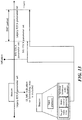
- FIG. 18 shows an operation in which a wireless communication terminal according to another embodiment of the present invention applies an MU EDCA parameter.
- the wireless communication terminal may apply the MU EDCA parameter set at the time point at which transmission of the trigger-based PPDU ends.
- the wireless communication terminal may set the MU EDCA timer at the time point at which transmission of the trigger-based PPDU ends.
- the wireless communication terminal may apply the MU EDCA parameter set at the time point at which transmission of the trigger-based PPDU ends. At this time, the wireless communication terminal may set the MU EDCA timer at the time point at which transmission of the trigger-based PPDU ends.
- the wireless communication terminal may apply the MU EDCA parameter set at the time point at which transmission of the trigger-based PPDU ends.
- the wireless communication terminal may set the MU EDCA timer at the time point at which transmission of the trigger-based PPDU ends.
- the wireless communication terminal receives the trigger frame TF from the base wireless communication terminal.
- the wireless communication terminal transmits a trigger-based PPDU HE TRIG PPDU including an A-MPDU whose immediate response context is DENIR to the base wireless communication terminal.
- the wireless communication terminal applies the MU EDCA parameter set at the time point at which transmission of the trigger-based PPDU HE TRIG PPDU ends and starts the MU EDCA timer.
- the wireless communication terminal may apply the MU EDCA parameter set when a predetermined time elapses after the time point at which transmission of the trigger-based PPDU ends.
- the wireless communication terminal may set the MU EDCA timer when a predetermined time elapses after the time point at which transmission of the trigger-based PPDU ends.
- the predetermined time may be a short inter frame space (SIFS).
- the predetermined time may be a time that is the sum of a predetermined representative ACK transmission time and an SIFS.
- the wireless communication terminal receives the trigger frame TF from the base wireless communication terminal. Upon receiving the trigger frame, the wireless communication terminal transmits a trigger-based PPDU HE TRIG PPDU including an A-MPDU whose immediate response context is DENIR to the base wireless communication terminal. The wireless communication terminal applies the MU EDCA parameter set when a predetermined time elapses after the time point at which transmission of the trigger-based PPDU HE TRIG PPDU ends and starts the MU EDCA timer. At this point, the predetermined time may be an SIFS. In another specific embodiment, the predetermined time may be a time that is the sum of the SIFS and the predetermined representative ACK transmission time Ack time.
- the wireless communication terminal may apply the MU EDCA parameter set based on an immediate response to the trigger-based PPDU transmission of another wireless communication terminal that transmits the trigger-based PPDU simultaneously with the wireless communication terminal.
- the wireless communication terminal may apply the MU EDCA parameter set based on an immediate response to the trigger-based PPDU transmission of another wireless communication terminal that transmits the trigger-based PPDU simultaneously with the wireless communication terminal.
- the wireless communication terminal when the wireless communication terminal receives an immediate response to the trigger-based PPDU transmission of another wireless communication terminal that transmits the trigger-based PPDU simultaneously with the wireless communication terminal, the wireless communication terminal may apply the MU EDCA parameter set.
- the wireless communication terminal may apply the MU EDCA parameter set when a predetermined period elapses from when transmitting the trigger-based PPDU transmitted by the wireless communication terminal.
- the time when the predetermined period elapses after transmitting the trigger-based PPDU transmitted by the wireless communication terminal may be the time when it elapses by aSIFSTime + aSlotTime + aRxPHYStart-Delay from the time point after PHY-TXEND.confirm primitive.
- the wireless communication terminal may set an MU EDCA timer based on an immediate response to the trigger-based PPDU transmission of another wireless communication terminal that transmits the trigger-based PPDU simultaneously with the wireless communication terminal.
- the wireless communication terminal may set an MU EDCA timer based on an immediate response to the trigger-based PPDU transmission of another wireless communication terminal that transmits the trigger-based PPDU simultaneously with the wireless communication terminal.
- the wireless communication terminal when the wireless communication terminal receives an immediate response to the trigger-based PPDU transmission of another wireless communication terminal that transmits the trigger-based PPDU simultaneously with the wireless communication terminal, the wireless communication terminal may set the MU EDCA timer.
- the wireless communication terminal may set the MU EDCA timer when a predetermined period elapses from when transmitting the trigger-based PPDU transmitted by the wireless communication terminal.
- the time when the predetermined period elapses after transmitting the trigger-based PPDU transmitted by the wireless communication terminal may be the time when it elapses by aSIFSTime + aSlotTime + aRxPHYStart-Delay from the time point after PHY-TXEND.confirm primitive.
- the wireless communication terminal receives a trigger frame TF and transmits a trigger-based PPDU HE TRIG PPDU including an A-MPDU whose immediate response context is DENIR to the base wireless communication terminal.
- the wireless communication terminal transmits a trigger-based PPDU HE TRIG PPDU
- the wireless communication terminal simultaneously detects the M-BA frame transmission for the trigger-based PPDU of another wireless communication terminal that transmits the trigger-based PPDU.
- the wireless communication terminal applies the MU EDCA parameter set at the time point at which reception of the M-BA frame for the trigger-based PPDU of another wireless communication terminal ends, and starts the MU EDCA timer.
- the wireless communication terminal When the wireless communication terminal does not receive the M-BA frame for the trigger-based PPDU of another wireless communication terminal as in the embodiment of FIG. 18(d) , the wireless communication terminal applies the MU EDCA parameter set at the time point at which it elapses by aSIFSTime + aSlotTime + aRxPHYStart-Delay from when transmitting the trigger-based PPDU HE TRIG PPDU, and starts the MU EDCA timer.
- the wireless communication terminal may apply the MU EDCA parameter set to the AC corresponding to the QoS data frame transmitted through the trigger-based PPDU as in the embodiment described with reference to FIG. 16 .
- the wireless communication terminal when a wireless communication terminal transmits a trigger-based PPDU, the wireless communication terminal may be restricted not to transmit a QoS data frame that does not request an ACK. Specifically, when the wireless communication terminal transmits the trigger-based PPDU, the wireless communication terminal may be restricted not to transmit the QoS data frame with the Ack policy subfield set to No Ack.
- FIG. 19 shows an operation in which a wireless communication terminal according to an embodiment of the present invention applies an MU EDCA parameter set.
- the EDCA parameter set may include a backoff timer and a parameter related to CW.
- the wireless communication terminal may change the value of the backoff timer currently used in the backoff procedure based on the second EDCA parameter set.
- the first EDCA parameter set may be a general EDCA parameter set
- the second EDCA parameter set may be an MU EDCA parameter set.
- the first EDCA parameter set may be an MU EDCA parameter set and the second EDCA parameter set may be a general EDCA parameter set. This is because if the wireless communication terminal does not change the value of the backoff timer when switching the EDCA parameter set, the effect of changing the channel access priority caused by the switching of the EDCA parameter set may not be immediately applied.
- the wireless communication terminal may multiply the backoff timer currently used in the backoff procedure with a value determined based on the second EDCA parameter set.
- the value determined based on the second EDCA parameter set may be a value determined based on the CW parameter value of the second EDCA parameter set.
- a value determined based on the second parameter set may be a value obtained by dividing the CWmin of the second EDCA parameter set by the CWmin of the first EDCA parameter set.
- the value determined based on the second EDCA parameter set may be a value obtained by dividing the CWmax of the second EDCA parameter set by the CWmax of the first EDCA parameter set.
- the wireless communication terminal when the value of the backoff timer currently used by the wireless communication terminal in the backoff procedure is smaller than the CWmin of the second EDCA parameter set, the wireless communication terminal may set the value of the backoff timer to the CWmin of the second EDCA parameter set. In addition, when the value of the backoff timer currently used by the wireless communication terminal in the backoff procedure is greater than the CWmax of the second EDCA parameter set, the wireless communication terminal may set the value of the backoff timer to the CWmax of the second EDCA parameter set.
- the wireless communication terminal may change the parameter value for CW currently used in the backoff procedure based on the second EDCA parameter set.
- the parameter for CW may include CWmin and CWmax.
- the EDCA parameter set may include a short retry limit and a long retry limit, which are parameters for adjusting the CW value according to the number of channel retransmission attempts.
- the first EDCA parameter set may be a general EDCA parameter set and the second EDCA parameter set may be an MU EDCA parameter set.
- the first EDCA parameter set may be an MU EDCA parameter set and the second EDCA parameter set may be a general EDCA parameter set.
- the wireless communication terminal may increase the value of CW in the backoff procedure. At this time, the value of CW is limited to the value of CWmax, and the wireless communication terminal may reset the value of CW to CWmin according to the retry limit value. This is because the restriction may not be applied when the wireless communication terminal switches the EDCA parameter set.
- the wireless communication terminal may set the CW value to CWmin of the second EDCA parameter set.
- the wireless communication terminal may set the CW value to the CWmax of the second EDCA parameter set.
- the wireless communication terminal may set the CW value to the CWmin of the second EDCA parameter set.
- the wireless communication terminal switches the legacy EDCA parameter set for the AC BE to the MU EDCA parameter set.
- the wireless communication terminal sets the backoff timer value BO MU [BE] to the product of a value a[AC] obtained based on the MU EDCA parameter set and the value of the backoff timer BO[BE] in the current backoff procedure.
- the wireless communication terminal sets the CW value CWmu[BE] to a larger value of the CW value CW[BE] in the current backoff procedure and CWmin CWmin[BE] in the MU EDCA parameter set.
- the wireless communication terminal converts the MU EDCA parameter set into a general EDCA parameter set
- the wireless communication terminal sets the CW value CW[BE] to a smaller value of CW CWmu[BE] value in the current backoff procedure and CWmax CWmax[BE] of the Legacy EDCA parameter set.
- FIG. 20 shows an operation of changing a CW value while a wireless communication terminal according to an embodiment of the present invention changes an EDCA parameter set.
- the wireless communication terminal changes the CW value in the following three situations during the backoff procedure.
- the wireless communication terminal changes the CW value according to the following rule.
- the situations of 1), 2) and 3) are all cases where the wireless communication terminal retries transmission due to transmission failure, internal contention failure, and the like. Also, in a) and b), the wireless communication terminal resets the CW value due to exceeding the number of retries. In c), the wireless communication terminal changes the CW value to retry the transmission. In a), b), and c), the wireless communication terminal operates without considering the case where the EDCA parameter set is changed. For example, the CW value corresponding to the AC is equal to CWmin, and the wireless communication terminal may apply the EDCA parameter set having the CWmin larger than the previous EDCA parameter set. At this time, the wireless communication terminal uses a CW value smaller than the CWmin of the new EDCA parameter set.
- the CW value corresponding to the AC is equal to CWmax
- the wireless communication terminal may apply the EDCA parameter set having CWmax smaller than the previous EDCA parameter set.
- the wireless communication terminal uses a CW value greater than the CWmax of the new EDCA parameter set.
- the wireless communication terminal may not change the CW value within the range of CWmin and CWmax. Therefore, the operation of the wireless communication terminal in c) may be changed as follows.
- the wireless communication terminal may operate as follows in the above-mentioned c).
- the wireless communication terminal may operate as follows in the above-mentioned c).
- FIG. 21 shows an operation of changing a CW value while a wireless communication terminal according to an embodiment of the present invention changes an EDCA parameter set.
- the wireless communication terminal may operate as follows in the above-mentioned c).
- the wireless communication terminal may operate as follows in the above-mentioned c).
- the wireless communication terminal may operate as follows in the above-mentioned c).
- the base wireless communication terminal may signal information on the MU EDCA parameter set.
- the specific format of the information on the MU EDCA parameter set will be described with reference to FIG. 22 to FIG. 23 .
- FIG. 22 shows a specific format of an MU EDCA parameter set element according to an embodiment of the present invention.
- the MU EDCA parameter set element includes an Element ID field and an Element ID extension field for identifying the MU EDCA parameter set element.
- the MU EDCA parameter set element includes an MU EDCA QoS Info field.
- the MU EDCA QoS Info field may include an MU EDCA Parameter Set Update Count field whose value is changed whenever the MU EDCA parameter set is changed. Specifically, when the base wireless communication terminal changes the MU EDCA parameter set, the base wireless communication terminal may increment the value of the MU EDCA Parameter Set Update Count field by one.
- the wireless communication terminal receiving the MU EDCA parameter set element may determine whether to change the MU EDCA parameter set based on the MU EDCA Parameter Set Update Count field value.
- Other fields in the MU QoS Info field other than the MU EDCA Parameter Set Update Count field may have the same format as the EDCA QoS Info field.
- the MU EDCA parameter set element may include information on the MU EDCA timer.
- the MU EDCA parameter set element may include information indicating the expiration time of the MU EDCA timer.
- the MU EDCA parameter set element includes a plurality of MU AC Parameter Record fields indicating information corresponding to each AC.
- the MU EDCA parameter set element includes an MU AC_BE Parameter Record field, an MU AC BK Parameter Record field, an MU AC_VI Parameter Record field, and an MU AC_VO Parameter Record field.
- the MU AC Parameter Record field may include an ACI/AIFSN field and an ECWmin/ECWmax field.
- the wireless communication terminal receiving the MU EDCA parameter set element applies the MU EDCA parameter set information corresponding to each AC based on the MU AC Parameter Record field.
- the wireless communication terminal receiving the MU EDCA parameter set element sets a management information base (MIB) attribute based on the MU AC Parameter Record field.
- MIB management information base
- FIG. 23 shows a specific format of an MU EDCA parameter set element according to another embodiment of the present invention.
- the base wireless communication terminal may transmit the MU QoS Info field using the beacon frame. Specifically, the base wireless communication terminal may transmit the MU QoS Info field through an element other than the MU EDCA parameter set element. In a specific embodiment, the base wireless communication terminal may transmit the MU QoS Info field through a QoS-related element other than the MU EDCA parameter set element.
- the base wireless communication terminal may transmit an MU EDCA parameter set element that does not include an MU QoS Info field.
- the specific format of the MU EDCA parameter set element may be as shown in FIG. 23 .
- the wireless communication terminal receiving the QoS Info field may determine whether the wireless communication terminal may not apply the changed EDCA parameter set based on the EDCA Parameter Set Update Count field.
- the wireless communication terminal may request the transmission of the EDCA parameter set element by transmitting the probe request frame to the base wireless communication terminal.
- the base wireless communication terminal When the base wireless communication terminal is not allowed to transmit the MU QoS Info field together with other elements other than the MU EDCA parameter set element, the MU QoS Info field may not perform the same role as the QoS Info field described above and the need to transmit the MU QoS Info field is also eliminated. Thus, when it is not allowed to transmit the MU QoS Info field together with other elements other than the MU EDCA parameter set element, the base wireless communication terminal may transmit an MU EDCA parameter set element that does not include the MU QoS Info field.
- the wireless communication terminal performs an internal contention procedure for data corresponding to each of a plurality of ACs using an internal EDCA queue. Specifically, the wireless communication terminal may operate a plurality of EDCA queues classified according to the access category of data stored in the queue. In addition, the wireless communication terminal may perform a backoff procedure for accessing a channel based on a time corresponding to a backoff timer in each of a plurality of EDCA queues. At this time, a method of using the EDCA queue by the wireless communication terminal will be described in detail with reference to FIG. 24 to FIG. 27 .
- FIG. 24 shows an EDCA operation after UL MU transmission of a wireless communication terminal according to an embodiment of the present invention.
- the wireless communication terminal may operate as follows at the boundary of each slot in the backoff procedure.
- the back off timer is 0 and the EDCA queue of the wireless communication terminal is empty, there is a problem because it is not clearly defined that what kind of operation the wireless communication terminal should perform. Specifically, in the following situations, when the backoff timer is 0, the EDCA queue of the wireless communication terminal may be empty.
- the base wireless communication terminal may trigger the uplink transmission of the wireless communication terminal by transmitting the trigger information.
- the base wireless communication terminal may obtain TXOP for transmission of trigger information through a backoff procedure. Therefore, the wireless communication terminal may maintain the backoff timer for AC of the data transmitted through the UL MU transmission in a state before the UL MU transmission.
- the wireless communication terminal may attempt to access the channel by resuming the backoff procedure for the corresponding AC. Data may not reach the EDCA queue of the AC until the backoff timer reaches 0.
- the wireless communication terminal if it is not the case where the wireless communication terminal attempts transmission and fails, even when the EDCA parameter set is changed, the CW value may be maintained as it is. Also, when the EDCA queue of the corresponding AC is empty and new data arrives in the corresponding EDCA queue, the wireless communication terminal obtains a random integer value within the current CW and sets a backoff timer. Thus, the wireless communication terminal may obtain a new backoff timer using the CW calculated according to the previous EDCA parameter set. For example, in the embodiment of FIG. 24 , the wireless communication terminal receives the trigger frame TF from the base wireless communication terminal. At this time, the wireless communication terminal stops the back off procedure for data in which AC is VO.
- the wireless communication terminal maintains the backoff timer of 4 and the CW value of 127.
- the wireless communication terminal transmits a trigger-based PPDU including QoS data TID 1 and TID 3 in which AC is VO to the base wireless communication terminal based on the trigger frame.
- the wireless communication terminal receives the M-BA frame from the base wireless communication terminal.
- the wireless communication terminal receives the M-BA frame and applies the MU EDCA parameter set as described above. Thereafter, the wireless communication terminal restarts the backoff procedure in which the value of the backoff timer is 4 and the CW value is 127.
- the channel accessed by the wireless communication terminal is idle for the time corresponding to the AIFS and the time corresponding to the backoff timer value of 4. Therefore, the back off timer becomes 0.
- the wireless communication terminal transmits all data in which AC is VO using the trigger-based PPDU, the EDCA queue for the VO is empty.
- the wireless communication terminal obtains the random value of 66 within the existing CW value of 127 and sets it as the back off timer value regardless of CWmin and CWmax of the MU EDCA parameter set.
- the wireless communication terminal transmits all data of the EDCA queue for the primary AC, and until the value of the backoff timer reaches 0, additional data may not arrive in the EDCA queue for the primary AC.
- the base wireless communication terminal may occupy the channel with the primary AC and transmit the data corresponding to the AC other than the primary AC together with the data corresponding to the primary AC.
- a backoff timer corresponding to AC other than the primary AC remains, and the EDCA queue of the corresponding AC may be empty.
- the wireless communication terminal may discard the corresponding (A-)MSDU.
- the back off timer may reach 0. If the EDCA queue is empty and the backoff timer is 0, the operation of the wireless communication terminal at the slot boundary will be described in detail with reference to FIGS. 25 to 27 .
- FIG. 25 shows the operation of a wireless communication terminal when the EDCA queue of the wireless communication terminal according to an embodiment of the present invention is empty and the backoff timer is 0.
- the wireless communication terminal may not perform any operation at the slot boundary. Specifically, the wireless communication terminal may maintain the backoff timer to be 0. Also, the wireless communication terminal may not start the transmission sequence. In a specific embodiment, the wireless communication terminal may maintain all state variables of the EDCA function (EDCAF) without modification.
- EDCAF EDCA function
- FIG. 26 shows the operation of a wireless communication terminal when the EDCA queue of the wireless communication terminal according to another embodiment of the present invention is empty and the backoff timer is 0.
- the wireless communication terminal may resume the backoff procedure at the slot boundary. At this time, the wireless communication terminal may maintain the CW value without modification. This is because it is not the case that the wireless communication terminal fails to transmit, and there is no need to double CW. Specifically, the wireless communication terminal may maintain all the state variables of the EDCAF except for the backoff timer. Also, when the EDCA queue is empty and the backoff timer is 0 again, the wireless communication terminal may start the backoff procedure again. In the embodiment of FIG. 26 , when the EDCA queue of the wireless communication terminal for VO is empty, the backoff timer BO[VO] reaches 0. The wireless communication terminal obtains a random value of 10 within the CW CW[VO] corresponding to the VO while maintaining all other EDCAF state variables, and sets the backoff timer BO[VO] using 10.
- FIG. 27 shows the operation of a wireless communication terminal when the EDCA queue of the wireless communication terminal according to another embodiment of the present invention is empty and the backoff timer is 0.
- the wireless communication terminal may initiate the EDCAF at the slot boundary. At this time, the wireless communication terminal may set CW to CWmin. Also, the wireless communication terminal may set QSRC and OLRC to initial values. Specifically, the wireless communication terminal may set QSRC and OLRC to 0. The wireless communication terminal initializes the EDCAF and then starts the backoff procedure again. At this time, the wireless communication terminal may maintain the CW value without modification. This is because it is not the case that the wireless communication terminal fails to transmit, and there is no need to double CW.
- the wireless communication terminal may initiate the EDCAF at the slot boundary again.
- the wireless communication terminal may not perform initialization.
- FIG. 28 shows the operation of a wireless communication terminal according to an embodiment of the present invention.
- the wireless communication terminal accesses the channel according to the priority of data to be transmitted (S2801). Specifically, the wireless communication terminal may access the channel according to the EDCA procedure described above. At this time, the wireless communication terminal may be a base wireless communication terminal. In addition, the wireless communication terminal may be a wireless communication terminal associated with the base wireless communication terminal.
- the wireless communication terminal that wirelessly communicates with a base wireless communication terminal may switch a parameter set used for channel access from a first parameter set to a second parameter set based on whether the UL MU transmission is scheduled. Specifically, the wireless communication terminal may switch the parameter set used for channel access from the first parameter set to the second parameter set based on whether the base wireless communication terminal triggers the UL MU transmission participation of the wireless communication terminal. Further, the base wireless communication terminal transmits a trigger frame to the wireless communication terminal, and the base wireless communication terminal may trigger the UL MU transmission participation of the wireless communication terminal. Depending on whether the user info field of the trigger frame includes the AID of the wireless communication terminal, the wireless communication terminal may determine whether the base wireless communication terminal triggers the UL MU transmission participation of the wireless communication terminal.
- the parameter set used for the channel access may be a set of parameters used to access the channel according to the priority of the data.
- the parameter set used for channel access may be the EDCA parameter set described above.
- the EDCA parameter set may include parameters for CW.
- the parameter for CW may include at least one of CWmin and CWmax.
- the EDCA parameter set may include a parameter value related to a predetermined time at which the wireless communication terminal waits to start the backoff procedure.
- the predetermined time may be the AIFS described above.
- the wireless communication terminal may determine whether to switch from the first parameter set to the second parameter set for each access category of data. Further, when the wireless communication terminal transmits the BSR, the wireless communication terminal may switch from the first parameter set to the second parameter set. In another specific embodiment, the wireless communication terminal may switch from the first parameter set to the second parameter set when the wireless communication terminal obtains information on the UL MU transmission. In another specific embodiment, the wireless communication terminal may transmit the trigger-based PPDU to the base wireless communication terminal according to the triggering of the base wireless communication terminal. At this time, the wireless communication terminal may switch from the first parameter set to the second parameter set according to an immediate response to the MPDU included in the trigger-based PPDU.
- the wireless communication terminal may switch from the first parameter set to the second parameter set when the wireless communication terminal receive an immediate response to the MPDU included in the trigger-based PPDU.
- the MPDU included in the trigger-based PPDU may be a QoS data frame.
- the wireless communication terminal may set the second parameter set timer for terminating the MU EDCA parameter set application. Specifically, based on whether the wireless communication terminal receives an immediate response to the MPDU included in the trigger-based PPDU, the wireless communication terminal may set the second parameter set timer according to the immediate response reception. When the second parameter set timer expires, the wireless communication terminal may be allowed to terminate the second parameter set application. Further, when the wireless communication terminal switches from the first parameter set to the second parameter set, the wireless communication terminal may set the second parameter set timer.
- the wireless communication terminal may determine when to switch from the first parameter set to the second parameter set based on the type of responding requested by the MPDU included in the trigger-based PPDU. In addition, the wireless communication terminal may determine when to set the second parameter set timer based on the type of responding requested by the MPDU included in the trigger-based PPDU. When the MPDU included in the trigger-based PPDU transmitted by the wireless communication terminal does not request the ACK, the wireless communication terminal may set the second parameter set timer when the transmission of the trigger-based PPDU ends. In addition, the wireless communication terminal may set a second parameter set timer for each access category.
- the wireless communication terminal may switch the parameter set from the first parameter set to the second parameter set and set the second parameter set timer when the transmission of the trigger based PPDU ends.
- the MPDU included in the trigger-based PPDU may be a QoS data frame.
- the specific operation of the wireless communication terminal may be the same as that described with reference to FIG. 6 through FIG. 18 .
- the parameters of the parameter set used in the backoff procedure may be changed.
- the wireless communication terminal may set the CW value to CWmax.
- the wireless communication terminal may set the CW value to CWmin.
- the wireless communication terminal may change the value of the backoff timer currently used in the backoff procedure based on the second parameter set.
- the wireless communication terminal may multiply the backoff timer currently used in the backoff procedure with a value determined based on the second parameter set.
- the wireless communication terminal may change the parameter value for CW currently used in the backoff procedure based on the second parameter set.
- the parameter for CW may include CWmin and CWmax.
- the wireless communication terminal may operate in the same manner as the embodiments described with reference to FIGS. 19 to 21 .
- the wireless communication terminal may operate a plurality of queues classified according to the access category of data stored in the queue.
- the wireless communication terminal may perform a backoff procedure for accessing a channel based on a time corresponding to a backoff timer in each of a plurality of queues.
- the queue may represent the EDCA queue described above.
- the wireless communication terminal may not perform any operation at the slot boundary.
- the wireless communication terminal may maintain the backoff timer to be 0.
- the wireless communication terminal may resume the backoff procedure at the slot boundary. At this time, the wireless communication terminal may maintain the CW value without modification.
- the wireless communication terminal may initialize a set of channel access parameters at a slot boundary. At this time, the wireless communication terminal may set CW to CWmin. Also, the wireless communication terminal may set QSRC and OLRC to initial values. Specifically, the wireless communication terminal may set QSRC and OLRC to 0. Specifically, the wireless communication terminal may operate in the same manner as the embodiments described with reference to FIGS. 24 to 27 .
- the wireless communication terminal transmits the data through the accessed channel (S2803).
- wireless LAN communication As an example, it is not limited thereto and may be applied to other communication systems such as cellular communication. Additionally, while the method, device, and system of the present invention are described in relation to specific embodiments thereof, some or all of the components or operations of the present invention may be implemented using a computer system having a general purpose hardware architecture.
Landscapes
- Engineering & Computer Science (AREA)
- Signal Processing (AREA)
- Computer Networks & Wireless Communication (AREA)
- Mobile Radio Communication Systems (AREA)
Priority Applications (1)
| Application Number | Priority Date | Filing Date | Title |
|---|---|---|---|
| EP22152570.2A EP4013179A1 (fr) | 2016-09-07 | 2017-09-07 | Procédé de communication sans fil utilisant un accès de canal distribué amélioré et terminal de communication sans fil utilisant ce dernier |
Applications Claiming Priority (8)
| Application Number | Priority Date | Filing Date | Title |
|---|---|---|---|
| KR20160114822 | 2016-09-07 | ||
| KR20160116877 | 2016-09-10 | ||
| KR20160116965 | 2016-09-12 | ||
| KR20160117898 | 2016-09-13 | ||
| KR20160122488 | 2016-09-23 | ||
| KR20160147189 | 2016-11-06 | ||
| KR20170022227 | 2017-02-20 | ||
| PCT/KR2017/009841 WO2018048229A1 (fr) | 2016-09-07 | 2017-09-07 | Procédé de communication sans fil utilisant un accès de canal distribué amélioré et un terminal de communication sans fil utilisant ce dernier |
Related Child Applications (1)
| Application Number | Title | Priority Date | Filing Date |
|---|---|---|---|
| EP22152570.2A Division EP4013179A1 (fr) | 2016-09-07 | 2017-09-07 | Procédé de communication sans fil utilisant un accès de canal distribué amélioré et terminal de communication sans fil utilisant ce dernier |
Publications (3)
| Publication Number | Publication Date |
|---|---|
| EP3512289A1 true EP3512289A1 (fr) | 2019-07-17 |
| EP3512289A4 EP3512289A4 (fr) | 2020-06-10 |
| EP3512289B1 EP3512289B1 (fr) | 2022-01-26 |
Family
ID=61562552
Family Applications (2)
| Application Number | Title | Priority Date | Filing Date |
|---|---|---|---|
| EP22152570.2A Pending EP4013179A1 (fr) | 2016-09-07 | 2017-09-07 | Procédé de communication sans fil utilisant un accès de canal distribué amélioré et terminal de communication sans fil utilisant ce dernier |
| EP17849113.0A Active EP3512289B1 (fr) | 2016-09-07 | 2017-09-07 | Procédé de communication sans fil utilisant un accès de canal distribué amélioré et un terminal de communication sans fil utilisant ce dernier |
Family Applications Before (1)
| Application Number | Title | Priority Date | Filing Date |
|---|---|---|---|
| EP22152570.2A Pending EP4013179A1 (fr) | 2016-09-07 | 2017-09-07 | Procédé de communication sans fil utilisant un accès de canal distribué amélioré et terminal de communication sans fil utilisant ce dernier |
Country Status (7)
| Country | Link |
|---|---|
| US (4) | US11116035B2 (fr) |
| EP (2) | EP4013179A1 (fr) |
| JP (1) | JP7076452B2 (fr) |
| KR (5) | KR20230160964A (fr) |
| CN (4) | CN115801210A (fr) |
| ES (1) | ES2911520T3 (fr) |
| WO (1) | WO2018048229A1 (fr) |
Cited By (1)
| Publication number | Priority date | Publication date | Assignee | Title |
|---|---|---|---|---|
| EP4090102A4 (fr) * | 2020-01-10 | 2023-09-27 | Nippon Telegraph And Telephone Corporation | Station de base, borne et procédé de communication sans fil |
Families Citing this family (15)
| Publication number | Priority date | Publication date | Assignee | Title |
|---|---|---|---|---|
| US9762487B2 (en) * | 2015-06-02 | 2017-09-12 | Newracom, Inc. | ACK policy for uplink and downlink MU PPDU |
| KR102374928B1 (ko) | 2016-05-11 | 2022-03-16 | 주식회사 윌러스표준기술연구소 | 랜덤 액세스 기반의 상향 다중 사용자 전송을 위한 무선 통신 단말 및 무선 통신 방법 |
| EP4319439A3 (fr) | 2016-07-06 | 2024-04-03 | Wilus Institute of Standards and Technology Inc. | Procédé de communication sans fil utilisant des informations de déclenchement, et terminal de communication sans fil l'utilisant |
| JP7076452B2 (ja) | 2016-09-07 | 2022-05-27 | ウィルス インスティテュート オブ スタンダーズ アンド テクノロジー インコーポレイティド | 向上された分散チャネルアクセスを使用する無線通信方法及びそれを使用する無線通信端末 |
| KR20220132045A (ko) | 2016-09-23 | 2022-09-29 | 주식회사 윌러스표준기술연구소 | 다중 사용자 edca 동작을 위한 무선 통신 단말 및 무선 통신 방법 |
| US11044726B1 (en) * | 2017-01-10 | 2021-06-22 | Marvell Asia Pte, Ltd. | Selection of transmission parameters for acknowledgment packets |
| US10750522B2 (en) * | 2017-11-02 | 2020-08-18 | Intel Corporation | Methods and apparatus to handle enhanced distributed channel access parameters |
| WO2020040552A1 (fr) * | 2018-08-23 | 2020-02-27 | 엘지전자 주식회사 | Procédé et dispositif pour obtenir des informations concernant une entité de communication fonctionnant dans une nouvelle bande dans un système lan sans fil |
| US11102740B2 (en) | 2018-08-31 | 2021-08-24 | Samsung Electronics Co., Ltd. | System and method for providing a synchronized mode for WLAN operation in a WLAN band |
| WO2020251197A1 (fr) * | 2019-06-13 | 2020-12-17 | 엘지전자 주식회사 | Procédé pour effectuer une communication à faible latence dans un système de réseau local sans fil |
| US11234243B2 (en) * | 2019-08-09 | 2022-01-25 | Samsung Electronics Co., Ltd | Method and system for transitioning station to uplink multi-user disable mode and uplink multi-user enable mode |
| CN113825248A (zh) * | 2020-06-18 | 2021-12-21 | 华为技术有限公司 | 多链路设备的信道接入方法及相关装置 |
| US20210410137A1 (en) * | 2020-06-25 | 2021-12-30 | Apple Inc. | Low-Latency Communication in a WLAN |
| CN113939038A (zh) * | 2021-10-29 | 2022-01-14 | 中国电子科技集团公司第五十四研究所 | WiFi网络的无线信道接入方法和系统及EDCA用户节点 |
| WO2023239176A1 (fr) * | 2022-06-08 | 2023-12-14 | 엘지전자 주식회사 | Procédé et dispositif de réalisation d'un fonctionnement basée sur une mise en correspondance d'un tid et d'une liaison dans un système lan sans fil |
Family Cites Families (63)
| Publication number | Priority date | Publication date | Assignee | Title |
|---|---|---|---|---|
| US7133422B2 (en) | 2002-01-31 | 2006-11-07 | Texas Instruments Incorporated | Implementing enhanced distributed coordinating function (EDCF) with a single hardware backoff counter |
| US8135404B2 (en) | 2008-09-29 | 2012-03-13 | Via Telecom, Inc. | Apparatus, system, and methods for handling attach procedure in mobile communication system |
| US8125969B2 (en) * | 2008-12-16 | 2012-02-28 | At&T Intellectual Property I, L.P. | Method and apparatus for adjusting EDCA channel access parameters |
| MY164719A (en) | 2010-02-12 | 2018-01-30 | Interdigital Patent Holdings Inc | Method and apparatus for optimizing uplink random access channel transmission |
| CN103563457B (zh) | 2011-05-31 | 2017-02-15 | Lg电子株式会社 | 发送和接收物理层会聚过程协议数据单元的方法及其装置 |
| US9191970B2 (en) | 2012-01-09 | 2015-11-17 | Qualcomm Incorporated | System and method of communication using distributed channel access parameters |
| BR112014019295A8 (pt) | 2012-02-05 | 2017-07-11 | Lg Electronics Inc | Processo e aparelho para acesso a canal por meio de quadro de pacotes de dados nulos em sistema lan sem fio |
| CA2869300C (fr) | 2012-04-02 | 2019-10-01 | Lg Electronics Inc. | Procede et appareil d'acces a un canal dans un systeme wlan |
| US9608789B2 (en) | 2012-05-11 | 2017-03-28 | Interdigital Patent Holdings, Inc. | Method and apparatus for transmitting acknowledgements in response to received frames |
| EP2852221B1 (fr) | 2012-05-15 | 2019-03-06 | LG Electronics Inc. | Procédé et appareil de balayage de faible puissance dans un système de réseau local sans fil |
| KR20150073165A (ko) * | 2012-10-16 | 2015-06-30 | 엘지전자 주식회사 | 무선랜에서 채널 액세스 방법 및 장치 |
| MY157062A (en) | 2012-10-30 | 2016-04-29 | Univ Putra Malaysia | A method for adjusting aggregation size based on acknowledgement (ack) bitmap |
| EP2938152B1 (fr) | 2012-12-19 | 2019-01-30 | LG Electronics Inc. | Procédé et dispositif de réduction de puissance dans un accès de canal de type fente d'un système lan sans fil |
| US9161275B2 (en) | 2013-03-08 | 2015-10-13 | Qualcomm Incorporated | Low latency 802.11 media access |
| JP6146568B2 (ja) | 2013-09-02 | 2017-06-14 | パナソニックIpマネジメント株式会社 | 無線通信装置及び無線通信方法 |
| US10230497B2 (en) | 2013-11-01 | 2019-03-12 | Qualcomm Incorporated | Protocols for multiple user frame exchanges |
| US9961510B2 (en) * | 2013-11-01 | 2018-05-01 | Qualcomm Incorporated | Protocols for multiple user frame exchanges |
| GB2520536B (en) | 2013-11-25 | 2017-05-03 | Canon Kk | Method and device for data communication in a communication network |
| CN105830506B (zh) * | 2013-12-18 | 2019-07-02 | Lg 电子株式会社 | 在支持用于下行链路的信道的无线lan系统中的功率减少模式操作方法及其装置 |
| US10009930B2 (en) | 2014-06-19 | 2018-06-26 | Lg Electronics Inc. | Method and apparatus for transmitting frame |
| WO2015199306A1 (fr) | 2014-06-26 | 2015-12-30 | 엘지전자(주) | Procédé de transmission de données de liaison montante multi-utilisateur dans un système de communications sans fil, et dispositif correspondant |
| US10499418B2 (en) | 2014-07-09 | 2019-12-03 | Qualcomm Incorporated | Methods and apparatus for multiple user uplink control and scheduling via aggregated frames |
| US20160057657A1 (en) * | 2014-08-20 | 2016-02-25 | Newracom, Inc. | Physical layer protocol data unit format including padding in a high efficiency wireless lan |
| WO2016028125A2 (fr) | 2014-08-21 | 2016-02-25 | 엘지전자(주) | Procédé destiné à une transmission en liaison montante dans un système de communication sans fil, et appareil correspondant |
| KR20170047259A (ko) | 2014-08-22 | 2017-05-04 | 엘지전자 주식회사 | 무선 통신 시스템에서 스테이션이 신호를 수신하는 방법 및 장치 |
| USRE49420E1 (en) | 2014-08-22 | 2023-02-14 | Lg Electronics Inc. | Method for uplink multi-user transmission in wireless communication system and apparatus therefor |
| EP3180956B1 (fr) * | 2014-08-29 | 2019-05-29 | MediaTek Inc. | Techniques d'accès à un canal classé par ordre de priorité prenant en compte une réutilisation spatiale |
| CN106605437B (zh) | 2014-09-01 | 2020-01-21 | 华为技术有限公司 | 选取信道的方法及发送端 |
| KR102373623B1 (ko) | 2014-09-03 | 2022-03-14 | 삼성전자주식회사 | 충돌 프리 랜덤 액세스를 위한 방법 |
| US20160080115A1 (en) | 2014-09-12 | 2016-03-17 | Samsung Electronics Co., Ltd. | Methods for efficient acknowledgement in wireless systems |
| KR102387854B1 (ko) | 2014-09-12 | 2022-04-19 | 한국전자통신연구원 | 분산 무선 통신 시스템에서 동기화 방법 및 이를 지원하는 단말 |
| KR101512731B1 (ko) | 2014-10-16 | 2015-04-20 | 연세대학교 산학협력단 | 통신 장치 및 방법, 그리고 그를 이용한 액세스 포인트 |
| US9949290B2 (en) | 2014-10-16 | 2018-04-17 | Newracom, Inc. | Bandwidth determination for multiple user transmission in a high efficiency wireless LAN |
| KR20160045023A (ko) | 2014-10-16 | 2016-04-26 | 뉴라컴 인코포레이티드 | 고효율 무선랜에서 상향링크 채널 액세스 방법 및 장치 |
| US9763223B2 (en) | 2014-10-16 | 2017-09-12 | Qualcomm Incorporated | Communication between devices of a neighbor aware network |
| KR101980714B1 (ko) | 2014-10-27 | 2019-05-21 | 엘지전자 주식회사 | 무선랜 시스템에서 다중 사용자 블록 확인응답 프레임 송수신 방법 및 이를 위한 장치 |
| US9948367B2 (en) | 2014-11-03 | 2018-04-17 | Qualcomm Incorporated | Methods and apparatus for acknowledging multiple user uplink transmissions |
| US10263750B2 (en) | 2014-12-23 | 2019-04-16 | Intel Corporation | Cross indication of queue size in a reverse direction protocol |
| US9942925B2 (en) * | 2015-01-07 | 2018-04-10 | Qualcomm, Incorporated | Station contention behavior in uplink multiple user protocols |
| US10194391B2 (en) | 2015-01-28 | 2019-01-29 | Qualcomm Incorporated | Triggered target wake time operation |
| US9930695B2 (en) | 2015-02-03 | 2018-03-27 | Intel IP Corporation | Orthogonal frequency-division multiple access distributed channel access |
| KR20160114822A (ko) | 2015-03-25 | 2016-10-06 | 인포뱅크 주식회사 | 사용자 정보 관리를 위한 서버 장치 |
| US10027499B2 (en) | 2015-04-07 | 2018-07-17 | Newracom, Inc. | Multi-user aggregation methods and systems for data and control frames |
| WO2016163849A1 (fr) | 2015-04-09 | 2016-10-13 | 엘지전자 주식회사 | Procédé et dispositif de transmission/réception de trame concernant une transmission multi-utilisateur dans un système de réseau local sans fil |
| WO2016172620A1 (fr) | 2015-04-24 | 2016-10-27 | Newracom, Inc. | Préambule et charge utile pour une transmission haute efficacité (he) |
| EP3286940A4 (fr) | 2015-04-24 | 2018-12-26 | Newracom, Inc. | Communication multi-utilisateur dans des réseaux sans fil |
| JP6515203B2 (ja) | 2015-04-29 | 2019-05-15 | インターデイジタル パテント ホールディングス インコーポレイテッド | Wlanシステムにおけるトリガーされた送信機会および複数ユーザack手順 |
| EP3294036B1 (fr) | 2015-05-27 | 2020-09-02 | Huawei Technologies Co., Ltd. | Procédé et dispositif d'accès à un canal |
| KR102446836B1 (ko) | 2015-06-18 | 2022-09-23 | 엘지전자 주식회사 | 무선 랜 시스템에서 상향링크 송신을 수행하는 방법 및 장치 |
| GB2543583B (en) | 2015-10-23 | 2018-05-16 | Canon Kk | Improved contention mechanism for access to random resource units in an 802.11 channel |
| US10742562B2 (en) | 2015-07-16 | 2020-08-11 | Samsung Electronics Co., Ltd. | Method and apparatus for adaptive control of contention window in LAA |
| US20180302924A1 (en) | 2015-10-26 | 2018-10-18 | Lg Electronics Inc. | Method for performing random access in wireless lan system and apparatus therefor |
| US10271353B2 (en) * | 2016-01-13 | 2019-04-23 | Qualcomm Incorporated | Methods and apparatus for selecting enhanced distributed channel access parameters for different stations |
| US10321486B2 (en) | 2016-02-18 | 2019-06-11 | Intel IP Corporation | Rules for handling multiple EDCA parameters |
| US10178694B2 (en) | 2016-03-01 | 2019-01-08 | Intel IP Corporation | Random access with carrier sensing |
| US10128989B2 (en) | 2016-03-01 | 2018-11-13 | Intel IP Corporation | Station (STA), access point (AP) and method for aggregation of data packets for uplink transmission |
| US10361832B2 (en) | 2016-04-22 | 2019-07-23 | Qualcomm Incorporated | Block acknowledgment generation and selection rules |
| US20170325264A1 (en) * | 2016-05-09 | 2017-11-09 | Qualcomm Incorporated | Backoff techniques for transitioning between single-user and multi-user modes |
| GB2552189B (en) * | 2016-07-13 | 2020-08-05 | Canon Kk | Restored fairness in an 802.11 network implementing resource units |
| WO2018016784A1 (fr) | 2016-07-22 | 2018-01-25 | 엘지전자 주식회사 | Procédé d'accès à un canal dans un système lan sans fil, et terminal sans fil l'utilisant |
| JP7076452B2 (ja) * | 2016-09-07 | 2022-05-27 | ウィルス インスティテュート オブ スタンダーズ アンド テクノロジー インコーポレイティド | 向上された分散チャネルアクセスを使用する無線通信方法及びそれを使用する無線通信端末 |
| US11006461B2 (en) | 2016-09-08 | 2021-05-11 | Panasonic Intellectual Property Corporation Of America | Orthogonal frequency division multiple access communication apparatus and communication method |
| KR20220132045A (ko) | 2016-09-23 | 2022-09-29 | 주식회사 윌러스표준기술연구소 | 다중 사용자 edca 동작을 위한 무선 통신 단말 및 무선 통신 방법 |
-
2017
- 2017-09-07 JP JP2019534619A patent/JP7076452B2/ja active Active
- 2017-09-07 CN CN202211378337.7A patent/CN115801210A/zh active Pending
- 2017-09-07 CN CN202211380666.5A patent/CN115765953A/zh active Pending
- 2017-09-07 KR KR1020237039548A patent/KR20230160964A/ko active Application Filing
- 2017-09-07 CN CN201780054732.0A patent/CN109792776B/zh active Active
- 2017-09-07 KR KR1020227018628A patent/KR102442012B1/ko active IP Right Grant
- 2017-09-07 KR KR1020227018630A patent/KR102442014B1/ko active IP Right Grant
- 2017-09-07 EP EP22152570.2A patent/EP4013179A1/fr active Pending
- 2017-09-07 KR KR1020197006093A patent/KR102407199B1/ko active IP Right Grant
- 2017-09-07 WO PCT/KR2017/009841 patent/WO2018048229A1/fr unknown
- 2017-09-07 ES ES17849113T patent/ES2911520T3/es active Active
- 2017-09-07 KR KR1020227030653A patent/KR102604379B1/ko active IP Right Grant
- 2017-09-07 CN CN202211378336.2A patent/CN115765952A/zh active Pending
- 2017-09-07 EP EP17849113.0A patent/EP3512289B1/fr active Active
-
2019
- 2019-03-06 US US16/294,883 patent/US11116035B2/en active Active
-
2021
- 2021-07-23 US US17/383,475 patent/US11523464B2/en active Active
- 2021-07-23 US US17/383,479 patent/US11516879B2/en active Active
-
2022
- 2022-11-03 US US17/979,767 patent/US11825558B2/en active Active
Cited By (1)
| Publication number | Priority date | Publication date | Assignee | Title |
|---|---|---|---|---|
| EP4090102A4 (fr) * | 2020-01-10 | 2023-09-27 | Nippon Telegraph And Telephone Corporation | Station de base, borne et procédé de communication sans fil |
Also Published As
| Publication number | Publication date |
|---|---|
| US20230055982A1 (en) | 2023-02-23 |
| CN109792776B (zh) | 2022-12-02 |
| US20210352760A1 (en) | 2021-11-11 |
| US20210352761A1 (en) | 2021-11-11 |
| CN115765952A (zh) | 2023-03-07 |
| ES2911520T3 (es) | 2022-05-19 |
| EP3512289B1 (fr) | 2022-01-26 |
| KR20220083843A (ko) | 2022-06-20 |
| WO2018048229A1 (fr) | 2018-03-15 |
| EP4013179A1 (fr) | 2022-06-15 |
| CN115801210A (zh) | 2023-03-14 |
| US11116035B2 (en) | 2021-09-07 |
| US11825558B2 (en) | 2023-11-21 |
| KR20230160964A (ko) | 2023-11-24 |
| KR102407199B1 (ko) | 2022-06-10 |
| US11523464B2 (en) | 2022-12-06 |
| KR102604379B1 (ko) | 2023-11-23 |
| KR20220082927A (ko) | 2022-06-17 |
| JP2019527005A (ja) | 2019-09-19 |
| KR20190040227A (ko) | 2019-04-17 |
| US11516879B2 (en) | 2022-11-29 |
| CN115765953A (zh) | 2023-03-07 |
| KR102442012B1 (ko) | 2022-09-13 |
| KR102442014B1 (ko) | 2022-09-13 |
| KR20220126806A (ko) | 2022-09-16 |
| JP7076452B2 (ja) | 2022-05-27 |
| US20190208571A1 (en) | 2019-07-04 |
| CN109792776A (zh) | 2019-05-21 |
| EP3512289A4 (fr) | 2020-06-10 |
Similar Documents
| Publication | Publication Date | Title |
|---|---|---|
| US11516879B2 (en) | Wireless communication method using enhanced distributed channel access, and wireless communication terminal using same | |
| CN110574441B (zh) | 使用bss标识符的无线通信方法和使用该方法的无线通信终端 | |
| US11528747B2 (en) | Wireless communication terminal and wireless communication method for multiuser EDCA operation | |
| KR102129283B1 (ko) | 다중 사용자 상향 전송을 위한 무선 통신 단말 및 무선 통신 방법 | |
| US11637679B2 (en) | Wireless communication method using trigger information, and wireless communication terminal | |
| KR102054052B1 (ko) | 무선 통신 방법 및 무선 통신 단말 | |
| US20240064865A1 (en) | Wireless communication method using enhanced distributed channel access, and wireless communication terminal using same | |
| KR102346678B1 (ko) | 무선 통신 방법 및 무선 통신 단말 | |
| KR20240063199A (ko) | 향상된 분산 채널 액세스를 사용하는 무선 통신 방법 및 이를 사용하는 무선 통신 단말 |
Legal Events
| Date | Code | Title | Description |
|---|---|---|---|
| STAA | Information on the status of an ep patent application or granted ep patent |
Free format text: STATUS: THE INTERNATIONAL PUBLICATION HAS BEEN MADE |
|
| PUAI | Public reference made under article 153(3) epc to a published international application that has entered the european phase |
Free format text: ORIGINAL CODE: 0009012 |
|
| STAA | Information on the status of an ep patent application or granted ep patent |
Free format text: STATUS: REQUEST FOR EXAMINATION WAS MADE |
|
| 17P | Request for examination filed |
Effective date: 20190404 |
|
| AK | Designated contracting states |
Kind code of ref document: A1 Designated state(s): AL AT BE BG CH CY CZ DE DK EE ES FI FR GB GR HR HU IE IS IT LI LT LU LV MC MK MT NL NO PL PT RO RS SE SI SK SM TR |
|
| AX | Request for extension of the european patent |
Extension state: BA ME |
|
| DAV | Request for validation of the european patent (deleted) | ||
| DAX | Request for extension of the european patent (deleted) | ||
| A4 | Supplementary search report drawn up and despatched |
Effective date: 20200512 |
|
| RIC1 | Information provided on ipc code assigned before grant |
Ipc: H04W 74/08 20090101ALI20200504BHEP Ipc: H04W 74/00 20090101AFI20200504BHEP Ipc: H04W 84/12 20090101ALN20200504BHEP |
|
| REG | Reference to a national code |
Ref country code: DE Ref legal event code: R079 Ref document number: 602017052885 Country of ref document: DE Free format text: PREVIOUS MAIN CLASS: H04W0074080000 Ipc: H04W0074000000 |
|
| GRAP | Despatch of communication of intention to grant a patent |
Free format text: ORIGINAL CODE: EPIDOSNIGR1 |
|
| STAA | Information on the status of an ep patent application or granted ep patent |
Free format text: STATUS: GRANT OF PATENT IS INTENDED |
|
| RIC1 | Information provided on ipc code assigned before grant |
Ipc: H04W 80/02 20090101ALN20210825BHEP Ipc: H04W 84/12 20090101ALN20210825BHEP Ipc: H04W 28/02 20090101ALI20210825BHEP Ipc: H04W 74/08 20090101ALI20210825BHEP Ipc: H04W 74/00 20090101AFI20210825BHEP |
|
| INTG | Intention to grant announced |
Effective date: 20210920 |
|
| GRAS | Grant fee paid |
Free format text: ORIGINAL CODE: EPIDOSNIGR3 |
|
| GRAA | (expected) grant |
Free format text: ORIGINAL CODE: 0009210 |
|
| STAA | Information on the status of an ep patent application or granted ep patent |
Free format text: STATUS: THE PATENT HAS BEEN GRANTED |
|
| AK | Designated contracting states |
Kind code of ref document: B1 Designated state(s): AL AT BE BG CH CY CZ DE DK EE ES FI FR GB GR HR HU IE IS IT LI LT LU LV MC MK MT NL NO PL PT RO RS SE SI SK SM TR |
|
| REG | Reference to a national code |
Ref country code: GB Ref legal event code: FG4D |
|
| REG | Reference to a national code |
Ref country code: CH Ref legal event code: EP |
|
| REG | Reference to a national code |
Ref country code: AT Ref legal event code: REF Ref document number: 1466295 Country of ref document: AT Kind code of ref document: T Effective date: 20220215 |
|
| REG | Reference to a national code |
Ref country code: IE Ref legal event code: FG4D |
|
| REG | Reference to a national code |
Ref country code: DE Ref legal event code: R096 Ref document number: 602017052885 Country of ref document: DE |
|
| REG | Reference to a national code |
Ref country code: NL Ref legal event code: FP |
|
| REG | Reference to a national code |
Ref country code: ES Ref legal event code: FG2A Ref document number: 2911520 Country of ref document: ES Kind code of ref document: T3 Effective date: 20220519 |
|
| REG | Reference to a national code |
Ref country code: LT Ref legal event code: MG9D |
|
| REG | Reference to a national code |
Ref country code: AT Ref legal event code: MK05 Ref document number: 1466295 Country of ref document: AT Kind code of ref document: T Effective date: 20220126 |
|
| PG25 | Lapsed in a contracting state [announced via postgrant information from national office to epo] |
Ref country code: SE Free format text: LAPSE BECAUSE OF FAILURE TO SUBMIT A TRANSLATION OF THE DESCRIPTION OR TO PAY THE FEE WITHIN THE PRESCRIBED TIME-LIMIT Effective date: 20220126 Ref country code: RS Free format text: LAPSE BECAUSE OF FAILURE TO SUBMIT A TRANSLATION OF THE DESCRIPTION OR TO PAY THE FEE WITHIN THE PRESCRIBED TIME-LIMIT Effective date: 20220126 Ref country code: PT Free format text: LAPSE BECAUSE OF FAILURE TO SUBMIT A TRANSLATION OF THE DESCRIPTION OR TO PAY THE FEE WITHIN THE PRESCRIBED TIME-LIMIT Effective date: 20220526 Ref country code: NO Free format text: LAPSE BECAUSE OF FAILURE TO SUBMIT A TRANSLATION OF THE DESCRIPTION OR TO PAY THE FEE WITHIN THE PRESCRIBED TIME-LIMIT Effective date: 20220426 Ref country code: LT Free format text: LAPSE BECAUSE OF FAILURE TO SUBMIT A TRANSLATION OF THE DESCRIPTION OR TO PAY THE FEE WITHIN THE PRESCRIBED TIME-LIMIT Effective date: 20220126 Ref country code: HR Free format text: LAPSE BECAUSE OF FAILURE TO SUBMIT A TRANSLATION OF THE DESCRIPTION OR TO PAY THE FEE WITHIN THE PRESCRIBED TIME-LIMIT Effective date: 20220126 Ref country code: BG Free format text: LAPSE BECAUSE OF FAILURE TO SUBMIT A TRANSLATION OF THE DESCRIPTION OR TO PAY THE FEE WITHIN THE PRESCRIBED TIME-LIMIT Effective date: 20220426 |
|
| PG25 | Lapsed in a contracting state [announced via postgrant information from national office to epo] |
Ref country code: PL Free format text: LAPSE BECAUSE OF FAILURE TO SUBMIT A TRANSLATION OF THE DESCRIPTION OR TO PAY THE FEE WITHIN THE PRESCRIBED TIME-LIMIT Effective date: 20220126 Ref country code: LV Free format text: LAPSE BECAUSE OF FAILURE TO SUBMIT A TRANSLATION OF THE DESCRIPTION OR TO PAY THE FEE WITHIN THE PRESCRIBED TIME-LIMIT Effective date: 20220126 Ref country code: GR Free format text: LAPSE BECAUSE OF FAILURE TO SUBMIT A TRANSLATION OF THE DESCRIPTION OR TO PAY THE FEE WITHIN THE PRESCRIBED TIME-LIMIT Effective date: 20220427 Ref country code: FI Free format text: LAPSE BECAUSE OF FAILURE TO SUBMIT A TRANSLATION OF THE DESCRIPTION OR TO PAY THE FEE WITHIN THE PRESCRIBED TIME-LIMIT Effective date: 20220126 Ref country code: AT Free format text: LAPSE BECAUSE OF FAILURE TO SUBMIT A TRANSLATION OF THE DESCRIPTION OR TO PAY THE FEE WITHIN THE PRESCRIBED TIME-LIMIT Effective date: 20220126 |
|
| PG25 | Lapsed in a contracting state [announced via postgrant information from national office to epo] |
Ref country code: IS Free format text: LAPSE BECAUSE OF FAILURE TO SUBMIT A TRANSLATION OF THE DESCRIPTION OR TO PAY THE FEE WITHIN THE PRESCRIBED TIME-LIMIT Effective date: 20220526 |
|
| REG | Reference to a national code |
Ref country code: DE Ref legal event code: R097 Ref document number: 602017052885 Country of ref document: DE |
|
| PG25 | Lapsed in a contracting state [announced via postgrant information from national office to epo] |
Ref country code: SM Free format text: LAPSE BECAUSE OF FAILURE TO SUBMIT A TRANSLATION OF THE DESCRIPTION OR TO PAY THE FEE WITHIN THE PRESCRIBED TIME-LIMIT Effective date: 20220126 Ref country code: SK Free format text: LAPSE BECAUSE OF FAILURE TO SUBMIT A TRANSLATION OF THE DESCRIPTION OR TO PAY THE FEE WITHIN THE PRESCRIBED TIME-LIMIT Effective date: 20220126 Ref country code: RO Free format text: LAPSE BECAUSE OF FAILURE TO SUBMIT A TRANSLATION OF THE DESCRIPTION OR TO PAY THE FEE WITHIN THE PRESCRIBED TIME-LIMIT Effective date: 20220126 Ref country code: EE Free format text: LAPSE BECAUSE OF FAILURE TO SUBMIT A TRANSLATION OF THE DESCRIPTION OR TO PAY THE FEE WITHIN THE PRESCRIBED TIME-LIMIT Effective date: 20220126 Ref country code: DK Free format text: LAPSE BECAUSE OF FAILURE TO SUBMIT A TRANSLATION OF THE DESCRIPTION OR TO PAY THE FEE WITHIN THE PRESCRIBED TIME-LIMIT Effective date: 20220126 Ref country code: CZ Free format text: LAPSE BECAUSE OF FAILURE TO SUBMIT A TRANSLATION OF THE DESCRIPTION OR TO PAY THE FEE WITHIN THE PRESCRIBED TIME-LIMIT Effective date: 20220126 |
|
| PG25 | Lapsed in a contracting state [announced via postgrant information from national office to epo] |
Ref country code: AL Free format text: LAPSE BECAUSE OF FAILURE TO SUBMIT A TRANSLATION OF THE DESCRIPTION OR TO PAY THE FEE WITHIN THE PRESCRIBED TIME-LIMIT Effective date: 20220126 |
|
| PLBE | No opposition filed within time limit |
Free format text: ORIGINAL CODE: 0009261 |
|
| STAA | Information on the status of an ep patent application or granted ep patent |
Free format text: STATUS: NO OPPOSITION FILED WITHIN TIME LIMIT |
|
| 26N | No opposition filed |
Effective date: 20221027 |
|
| PG25 | Lapsed in a contracting state [announced via postgrant information from national office to epo] |
Ref country code: SI Free format text: LAPSE BECAUSE OF FAILURE TO SUBMIT A TRANSLATION OF THE DESCRIPTION OR TO PAY THE FEE WITHIN THE PRESCRIBED TIME-LIMIT Effective date: 20220126 |
|
| REG | Reference to a national code |
Ref country code: DE Ref legal event code: R088 Ref document number: 602017052885 Country of ref document: DE |
|
| PG25 | Lapsed in a contracting state [announced via postgrant information from national office to epo] |
Ref country code: MC Free format text: LAPSE BECAUSE OF FAILURE TO SUBMIT A TRANSLATION OF THE DESCRIPTION OR TO PAY THE FEE WITHIN THE PRESCRIBED TIME-LIMIT Effective date: 20220126 |
|
| REG | Reference to a national code |
Ref country code: CH Ref legal event code: PL |
|
| REG | Reference to a national code |
Ref country code: BE Ref legal event code: MM Effective date: 20220930 |
|
| REG | Reference to a national code |
Ref country code: NL Ref legal event code: QB Free format text: DETAILS LICENCE OR PLEDGE: LICENCE, NEW LICENCE REGISTRATION, EXCLUSIEVE LICENTIE VERLEEND DOOR SK TELECOM CO., LTD. AAN WILUS INSTITUTE OF STANDARDS AND TECHNOLOGY INC. Name of requester: WILUS INSTITUTE OF STANDARDS AND TECHNOLOGY INC. Effective date: 20230516 Ref country code: ES Ref legal event code: GD2A Effective date: 20230607 |
|
| REG | Reference to a national code |
Ref country code: GB Ref legal event code: 732E Free format text: REGISTERED BETWEEN 20230518 AND 20230524 |
|
| PG25 | Lapsed in a contracting state [announced via postgrant information from national office to epo] |
Ref country code: LU Free format text: LAPSE BECAUSE OF NON-PAYMENT OF DUE FEES Effective date: 20220907 |
|
| P01 | Opt-out of the competence of the unified patent court (upc) registered |
Effective date: 20230603 |
|
| PG25 | Lapsed in a contracting state [announced via postgrant information from national office to epo] |
Ref country code: LI Free format text: LAPSE BECAUSE OF NON-PAYMENT OF DUE FEES Effective date: 20220930 Ref country code: IE Free format text: LAPSE BECAUSE OF NON-PAYMENT OF DUE FEES Effective date: 20220907 Ref country code: CH Free format text: LAPSE BECAUSE OF NON-PAYMENT OF DUE FEES Effective date: 20220930 |
|
| PGFP | Annual fee paid to national office [announced via postgrant information from national office to epo] |
Ref country code: NL Payment date: 20230719 Year of fee payment: 7 |
|
| PG25 | Lapsed in a contracting state [announced via postgrant information from national office to epo] |
Ref country code: BE Free format text: LAPSE BECAUSE OF NON-PAYMENT OF DUE FEES Effective date: 20220930 |
|
| PGFP | Annual fee paid to national office [announced via postgrant information from national office to epo] |
Ref country code: TR Payment date: 20230906 Year of fee payment: 7 Ref country code: IT Payment date: 20230810 Year of fee payment: 7 Ref country code: GB Payment date: 20230720 Year of fee payment: 7 |
|
| PGFP | Annual fee paid to national office [announced via postgrant information from national office to epo] |
Ref country code: FR Payment date: 20230703 Year of fee payment: 7 Ref country code: DE Payment date: 20230712 Year of fee payment: 7 |
|
| PGFP | Annual fee paid to national office [announced via postgrant information from national office to epo] |
Ref country code: ES Payment date: 20231005 Year of fee payment: 7 |
|
| REG | Reference to a national code |
Ref country code: DE Ref legal event code: R039 Ref document number: 602017052885 Country of ref document: DE Ref country code: DE Ref legal event code: R008 Ref document number: 602017052885 Country of ref document: DE |
|
| REG | Reference to a national code |
Ref country code: DE Ref legal event code: R082 Ref document number: 602017052885 Country of ref document: DE Representative=s name: EISENFUEHR SPEISER PATENTANWAELTE RECHTSANWAEL, DE |
|
| PG25 | Lapsed in a contracting state [announced via postgrant information from national office to epo] |
Ref country code: HU Free format text: LAPSE BECAUSE OF FAILURE TO SUBMIT A TRANSLATION OF THE DESCRIPTION OR TO PAY THE FEE WITHIN THE PRESCRIBED TIME-LIMIT; INVALID AB INITIO Effective date: 20170907 |
|
| PG25 | Lapsed in a contracting state [announced via postgrant information from national office to epo] |
Ref country code: CY Free format text: LAPSE BECAUSE OF FAILURE TO SUBMIT A TRANSLATION OF THE DESCRIPTION OR TO PAY THE FEE WITHIN THE PRESCRIBED TIME-LIMIT Effective date: 20220126 |