EP3512183B1 - Portable terminal cover - Google Patents
Portable terminal cover Download PDFInfo
- Publication number
- EP3512183B1 EP3512183B1 EP17848898.7A EP17848898A EP3512183B1 EP 3512183 B1 EP3512183 B1 EP 3512183B1 EP 17848898 A EP17848898 A EP 17848898A EP 3512183 B1 EP3512183 B1 EP 3512183B1
- Authority
- EP
- European Patent Office
- Prior art keywords
- portable terminal
- band
- main body
- terminal cover
- cover main
- Prior art date
- Legal status (The legal status is an assumption and is not a legal conclusion. Google has not performed a legal analysis and makes no representation as to the accuracy of the status listed.)
- Active
Links
Images


Classifications
-
- A—HUMAN NECESSITIES
- A45—HAND OR TRAVELLING ARTICLES
- A45C—PURSES; LUGGAGE; HAND CARRIED BAGS
- A45C11/00—Receptacles for purposes not provided for in groups A45C1/00-A45C9/00
-
- A—HUMAN NECESSITIES
- A45—HAND OR TRAVELLING ARTICLES
- A45C—PURSES; LUGGAGE; HAND CARRIED BAGS
- A45C11/00—Receptacles for purposes not provided for in groups A45C1/00-A45C9/00
- A45C11/002—Receptacles for purposes not provided for in groups A45C1/00-A45C9/00 for storing portable handheld communication devices, e.g. pagers or smart phones
-
- A—HUMAN NECESSITIES
- A45—HAND OR TRAVELLING ARTICLES
- A45C—PURSES; LUGGAGE; HAND CARRIED BAGS
- A45C13/00—Details; Accessories
- A45C13/02—Interior fittings; Means, e.g. inserts, for holding and packing articles
-
- A—HUMAN NECESSITIES
- A45—HAND OR TRAVELLING ARTICLES
- A45C—PURSES; LUGGAGE; HAND CARRIED BAGS
- A45C13/00—Details; Accessories
- A45C13/10—Arrangement of fasteners
-
- A—HUMAN NECESSITIES
- A45—HAND OR TRAVELLING ARTICLES
- A45C—PURSES; LUGGAGE; HAND CARRIED BAGS
- A45C13/00—Details; Accessories
- A45C13/30—Straps; Bands
-
- A—HUMAN NECESSITIES
- A45—HAND OR TRAVELLING ARTICLES
- A45C—PURSES; LUGGAGE; HAND CARRIED BAGS
- A45C7/00—Collapsible or extensible purses, luggage, bags or the like
- A45C7/0018—Rigid or semi-rigid luggage
-
- A—HUMAN NECESSITIES
- A45—HAND OR TRAVELLING ARTICLES
- A45C—PURSES; LUGGAGE; HAND CARRIED BAGS
- A45C7/00—Collapsible or extensible purses, luggage, bags or the like
- A45C7/0059—Flexible luggage; Hand bags
-
- H—ELECTRICITY
- H04—ELECTRIC COMMUNICATION TECHNIQUE
- H04M—TELEPHONIC COMMUNICATION
- H04M1/00—Substation equipment, e.g. for use by subscribers
- H04M1/02—Constructional features of telephone sets
- H04M1/04—Supports for telephone transmitters or receivers
-
- H—ELECTRICITY
- H04—ELECTRIC COMMUNICATION TECHNIQUE
- H04M—TELEPHONIC COMMUNICATION
- H04M1/00—Substation equipment, e.g. for use by subscribers
- H04M1/02—Constructional features of telephone sets
- H04M1/11—Supports for sets, e.g. incorporating armrests
-
- H—ELECTRICITY
- H05—ELECTRIC TECHNIQUES NOT OTHERWISE PROVIDED FOR
- H05K—PRINTED CIRCUITS; CASINGS OR CONSTRUCTIONAL DETAILS OF ELECTRIC APPARATUS; MANUFACTURE OF ASSEMBLAGES OF ELECTRICAL COMPONENTS
- H05K5/00—Casings, cabinets or drawers for electric apparatus
- H05K5/02—Details
- H05K5/03—Covers
-
- A—HUMAN NECESSITIES
- A45—HAND OR TRAVELLING ARTICLES
- A45C—PURSES; LUGGAGE; HAND CARRIED BAGS
- A45C11/00—Receptacles for purposes not provided for in groups A45C1/00-A45C9/00
- A45C11/003—Receptacles for purposes not provided for in groups A45C1/00-A45C9/00 for storing portable computing devices, e.g. laptops, tablets or calculators
-
- A—HUMAN NECESSITIES
- A45—HAND OR TRAVELLING ARTICLES
- A45C—PURSES; LUGGAGE; HAND CARRIED BAGS
- A45C13/00—Details; Accessories
- A45C13/10—Arrangement of fasteners
- A45C2013/1015—Arrangement of fasteners of hook and loop type
-
- A—HUMAN NECESSITIES
- A45—HAND OR TRAVELLING ARTICLES
- A45C—PURSES; LUGGAGE; HAND CARRIED BAGS
- A45C13/00—Details; Accessories
- A45C13/10—Arrangement of fasteners
- A45C13/1038—Arrangement of fasteners of flexible ties
- A45C2013/1061—Arrangement of fasteners of flexible ties of elastic straps or bands
Definitions
- the present invention relates to a portable terminal cover.
- a portable terminal cover is often used for a portable terminal.
- Typical examples of the portable terminal cover include a case type such as a soft case and a hard case, and a notebook type.
- the notebook type is described in, for example, Patent Literature 1 described below.
- the present invention provides a portable terminal cover including: a portable terminal cover main body portion made of a freely foldable material; and a band portion mounted to the portable terminal cover main body portion, in which the band portion is sandwiched between a portable terminal and a portable terminal case or other retainer to which the portable terminal is detachably mounted.
- the portable terminal and the portable terminal case or other retainer can be fixed to, attached to, and detached from the portable terminal cover main body portion through the band portion. Further, even when a camera hole is not formed in the portable terminal cover main body portion, with the band portion, shooting can be performed without a detaching operation under a state in which the portable terminal is mounted to the portable terminal cover main body portion.
- the term "retainer” including the term described in CLAIMS refers to not only a retainer configured to fix the portable terminal by holding the entirety of the portable terminal but also a retainer configured to fix the portable terminal by holding at least a part of the portable terminal.
- the portable terminal cover can surround the portable terminal and the portable terminal case or other retainer in an integrated manner and is continuously usable irrespective of shapes of the portable terminal in terms of a size, an operation button, a camera position, and the like.
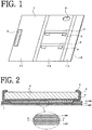
- FIG. 1 is a view for illustrating a spread state of a portable terminal cover main body portion 1 of a side-open notebook type according to a first embodiment of the present invention.
- the portable terminal cover main body portion 1 includes, for example, an inner left surface 1-1, an inner right surface 1-2, a flap portion 1-3, and the like and is used as a folding portable terminal cover.
- the inner right surface 1-2 is used as a mounting portion for a portable terminal.
- the mounting portion includes band portions 2 each configured to mount a portable terminal case 3 or other retainer and a portable terminal 4 (see FIG. 4 ) to the portable terminal cover main body portion 1. It is preferred that each band portion 2 be arranged at a position at which the band portion 2 is prevented from overlapping operation devices of the portable terminal 4 such as a power button. When there is no fear of impairing functions of the operation devices, the band portion 2 may be arranged at a position of overlapping the operation devices.
- a hook-and-loop fastener 5 is also provided on an outer back surface 1-5, and is attached to another hook-and-loop fastener 5 for use when the portable terminal cover main body portion 1 is closed.
- the mounting portion has a main body camera hole 6 and band holes 8 through which the band portion 2 is inserted.
- the inner right surface 1-2 is used as the mounting portion for a portable terminal and the portable terminal cover main body portion 1 is opened leftward with a long side of the portable terminal being a fulcrum
- the inner left surface 1-1 may be used as the mounting portion and the portable terminal cover main body portion 1 may be opened rightward.
- the band portion 2 may be arranged on the mounting portion without forming the band hole 8.
- the portable terminal cover main body portion 1 is made of, for example, any one of rubber, silicone, cloth, leather, synthetic leather, a synthetic resin, and metal or of a combination thereof. It is only required that the band portion 2 or a band portion 2-1 described later (see FIG. 8 ) be sandwiched between the portable terminal case 3 or other retainer and the portable terminal 4 (see FIG. 2 ).
- the band portion 2 or the band portion 2-1 is made of, for example, any one of rubber, silicone, cloth, a cord, a tape, leather, synthetic leather, a synthetic resin, and metal or of a combination thereof.
- the band portion 2 may be made of a combination of a plurality of materials.
- the cover main body portion 1 side may be made of cloth, and the cloth portion may be connected through use of rubber.
- FIG. 2 is a partial sectional view for illustrating the band portion 2 of the portable terminal cover main body portion 1, and corresponds to a sectional view taken along the line AA' of FIG. 4 described later (see FIG. 4 ).
- the band portion 2 is formed into a shape of wrapping the portable terminal case 3 or other retainer, and is sandwiched between the portable terminal case 3 or other retainer and the portable terminal 4.
- the portable terminal case 3 or other retainer and the portable terminal 4 are fixed to the portable terminal cover main body portion 1 by the band portions 2, and thus are held in an integrated manner.
- a portable terminal cover inner portion 1-100, a portable terminal cover outer portion 1-200, a core member 7, and the like are provided, and are fixed to each other at, for example, peripheries and surfaces thereof.
- the band holes 8 are formed in the portable terminal cover inner portion 1-100, and the band portion 2 is inserted through the band holes 8. Both ends of the band portion 2 are joined and fixed to each other, and the band portion 2 is fixed to the core member 7 and the like at a plurality of portions.
- a method of fixing portions of the band portion together or fixing the band portion to the portable terminal cover main body portion 1, the mounting portion, the core member 7, and the like includes, for example, any one of sewing, bonding, adhesion, welding, joining, coupling, engagement, a fastener, and a fixing device or a combination thereof, and the band portion may be fixed at a plurality of portions. Further, the band portion 2 may be fastened, fixed, or detachably fixed.
- the core member 7 or the like provides effects of preventing the fixed portions of the band portion 2 from being seen on the portable terminal cover inner portion 1-100 or the portable terminal cover outer portion 1-200 so as to keep aesthetic appearance, and protecting the band portion 2 against an external force.
- FIG. 3 is a view for illustrating a spread state of the portable terminal cover main body portion 1 of FIG. 1 to which the portable terminal case 3 or other retainer is mounted.
- the portable terminal case 3 includes, for example, a soft case, a hard case, or a retainer for a portable terminal, or the like, which are commercially available in general and others.
- the portable terminal case 3 or other retainer is mounted to the portable terminal cover main body portion 1.
- the portable terminal case 3 or other retainer is inserted into a loop of each of the band portions 2 of the inner right surface 1-2 being the mounting portion.
- the band portions 2 are positioned on an outer side of the portable terminal case 3 or other retainer.
- a position of the main body camera hole 6 and a position of a case camera hole 6-1 are matched with each other.
- FIG. 4 is a view for illustrating a spread state of the portable terminal cover main body portion 1 of FIG. 3 to which the portable terminal 4 is mounted.
- the portable terminal 4 is fitted to the portable terminal case 3 or other retainer and the band portions 2 illustrated in FIG. 3 from above.
- the band portions 2 are sandwiched between the portable terminal case 3 or other retainer and the portable terminal 4 to be positioned below the portable terminal 4. Therefore, the band portions 2 do not overlap and obstruct a touch panel display of the portable terminal 4 so that the touch panel display is operable.
- the sandwiched band portions are fixed by being pressed by side surfaces, a back surface, or the like of the portable terminal 4, and thus are reliably integrated with the portable terminal cover main body portion 1.
- the portable terminal case 3 or other retainer is not fixed to the portable terminal cover main body portion 1 through bonding, adhesion, or the like, and hence the portable terminal case 3 or other retainer and the portable terminal 4 can be easily and repeatedly attached to and detached from the portable terminal cover main body portion 1 through the band portions.
- the portable terminal 4 is attachable to and detachable from the portable terminal cover main body portion 1, and hence there is easily allowed use of two forms of a cover, specifically, a case form in which the portable terminal 4 is mounted to the portable terminal case 3 or other retainer and a notebook form in which the portable terminal 4 is mounted to the portable terminal cover main body portion 1. Further, the portable terminal cover according to the present invention is adaptable to various types of portable terminals that differ from each other in size, operation button, camera position, and the like, and hence is continuously usable.
- the portable terminal cover according to the present invention is adaptable to such change as long as the portable terminal can be mounted to a retainer through the band portion.
- a universal design can be attained.
- FIG. 5 is a view for illustrating a closed state of the portable terminal cover main body portion 1 according to the first embodiment.
- the portable terminal cover main body portion 1 is closed under a state in which another surface of the mounting portion is folded.
- the flap portion 1-3 is folded over the inner right surface 1-2, and the inner left surface 1-1 is folded to be laid on flap portion 1-3.
- the portable terminal cover main body portion 1 is closed by a fastener such as the hook-and-loop fastener 5.
- the flap portion 1-3 is laid inside the outer back surface 1-5, and is not laid on the outer back surface 1-5. As a result, decoration is easily made on the entire outer back surface 1-5.
- the closing method is not limited to the above-mentioned method.
- FIG. 6 is a view of a spread state of the portable terminal cover main body portion 1 of an up-and-down-open notebook type according to a second embodiment of the present invention.
- the portable terminal cover main body portion 1 according to the second embodiment has a shape obtained by changing that according to the first embodiment into an up-and-down-open type, and is folded in an up-and-down direction.
- an inner lower surface 1-7 is used as the mounting portion and the portable terminal cover main body portion 1 is opened upward with a short side of the portable terminal being a fulcrum
- an inner upper surface 1-6 may be used as the mounting portion and the portable terminal cover main body portion 1 may be opened downward.
- the inner lower surface 1-7 includes a bending portion 1-8.
- the bending portion 1-8 is formed below the above-mentioned camera hole. During use of a camera, the camera hole is exposed by bending the inner lower surface 1-7 from the bending portion 1-8 so that shooting can be performed (see FIG. 7 ). An entire part of the bending portion 1-8 corresponding to an upper part of the portable terminal 4 may be bent, or only a part of the bending portion 1-8 may be bent. When the inner lower surface 1-7 is made of a soft material such as cloth, the bending portion 1-8 is not required.
- FIG. 7 is a view for illustrating a camera use example in a case of the portable terminal cover main body portion 1 of the up-and-down-open notebook type of FIG. 6 according to a third embodiment of the present invention.
- the main body camera hole 6 is not formed, and a part of the portable terminal cover main body portion 1 corresponding to the camera portion of the portable terminal 4 is configured to be bendable. Similarly, also in the side-open notebook type of FIG. 4 , shooting can be performed by only bending the upper part of the portable terminal cover main body portion 1 backward.
- the main body camera hole 6 is not formed in the side-open notebook type of FIG. 4 , and the band portions 2 expand and contract when the portable terminal case 3 or other retainer, to which the portable terminal 4 is fitted, is pushed upward from below by a thumb or the like. As a result, the portable terminal 4 is slid upward, and similarly to the case illustrated in FIG. 7 , the case camera hole 6-1 and the camera portion of the portable terminal 4 are exposed to the outside from the upper part of the portable terminal cover main body portion 1 so that shooting can be performed. Also in the up-and-down-open notebook type of FIG.
- shooting can be performed by bending backward a portion between the inner upper surface 1-6 and the inner lower surface 1-7 being the mounting portion, or similarly pushing the portable terminal 4 upward with a configuration in which the inner upper surface 1-6 is used as the mounting portion and the hook-and-loop fastener 5 is provided on the back surface.
- the portable terminal cover main body portion 1 can be used by any one of the ways, and thus can be applied to various types of portable terminals that differ from each other in shape, camera position, and the like.
- the portable terminal case 3 or other retainer is not fixed to the portable terminal cover main body portion 1 through bonding, adhesion, or the like.
- the part of the portable terminal cover main body portion 1 corresponding to the camera portion of the portable terminal 4 can be folded at the bending portion 1-8, or the portable terminal case 3 or other retainer can be pushed upward from below so as to be slid.
- the main body camera hole 6 is not formed in the portable terminal cover main body portion 1 so that a camera lens of the portable terminal 4 is covered.
- FIG. 8 is a view for illustrating a spread state of a portable terminal cover main body portion according to a fourth embodiment of the present invention including a modification of the band portion 2 according to the first embodiment to the third embodiment.
- a band portion 2-1 is different from the band portion 2 in shape and the like, but a material example, a fixing method, and the like for the band portion 2-1 are the same as those for the band portion 2 according to the first embodiment to the third embodiment.
- No band hole 8 is formed, and only an inner right or inner left side of the band portion 2-1 is directly fixed by a fixing portion 9.
- right and left two band portions 2-1 may be joined into one member, and, for example, a center of the two band portions 2-1 may be fixed by the fixing portion 9.
- the band portion 2-1 may be formed of the band portion 2, or a combination of the band portion 2 and the band portion 2-1 may be adopted (see FIG. 10 ).
- the band portions 2-1 of FIG. 8 are configured to hold the portable terminal at right and left long sides of the portable terminal, the band portions 2-1 may be provided to hold upper and lower short sides of the portable terminal, any one of upper, lower, right, and left sides of the portable terminal, or a combination of a plurality of sides among the upper, lower, right, and left sides.
- the flap portion 1-3 is provided on only a part of one side of the portable terminal.
- the two band portions 2-1 are illustrated, but a configuration including a single band portion 2-1 may be adopted. Further, the two band portions 2 may differ from each other in size, position, and the like.
- FIG. 9 is a view for illustrating a spread state of the portable terminal cover main body portion of FIG. 8 to which the portable terminal case 3 or other retainer is mounted.
- the band portions 2-1 of FIG. 8 are raised and laid on the portable terminal case 3 or other retainer in conformity to the portable terminal case 3 or other retainer, and then the portable terminal 4 is fitted into the portable terminal case 3 or other retainer from above.
- the band portion 2 wraps an entire girth of the portable terminal case 3 or other retainer.
- the band portion 2-1 has such a structure as to partially wrap the girth of the portable terminal case 3 or other retainer.
- the band portion 2-1 can also provide the same effects as those of the band portion 2 in the first embodiment to the third embodiment, and is adaptable to the portable terminals 4 that differ from each other in shape and the like such as size.
- FIG. 10 is a view for illustrating a portable terminal cover according to a fifth embodiment of the present invention.
- the band portions 2 are also provided on the inner left surface 1-1 so that two portable terminals can be mounted to the portable terminal cover main body portion 1.
- the portable terminal can be mounted to each of the inner left surface 1-1 and the inner right surface 1-2.
- the band portions 2 may be provided on both sides of the inner left surface 1-1 or the inner right surface 1-2 so that the portable terminals can be mounted to the both sides.
- An outer surface and an inner surface of the portable terminal cover main body portion 1 according to the first embodiment to the fifth embodiment may have various patterns, decorations, functions, and the like.
- a pocket, a display protector, a contamination preventing member, or a dirt wiper may be provided, or the portable terminal cover main body portion 1 may have functions of the above-mentioned members.
- the portable terminal cover main body portion 1 is of the right-open or left-open horizontal type or the up-and-down-open vertical type.
- the portable terminal cover main body portion 1 may be of a type including only the mounting portion, a type including a plurality of surfaces, a bifold type, a multifold type, or a type without the flap portion 1-3.
- the portable terminal cover main body portion 1 has a flat surface, but, for example, a three-dimensional, deformed, decorative surface, or the like may be used as the portable terminal cover main body portion 1, and the band portion, the mounting portion with the band portion, or the like may be provided.
- the portable terminal cover main body portion 1 may be shaped into an animal, a food, a vehicle, or the like, made as a stuffed toy, or the like.
- the mounting portion with the band portion and the core member 7, which are modified in size and shape, may be fixed to the portable terminal cover inner portion 1-100 or the like.
- the portable terminal cover is exemplified, but the present invention may be applied to, for example, a tablet device and the like.
- the band portions may be provided as any number of pieces, sheets, or plies, and have any shape such as linear, curved, deformed, patterned, or decorative shapes.
- the band portions may be provided in vertical, horizontal, oblique, parallel, or crossing arrangement or combined arrangement.
- the band portions may be arranged in parallel to each other at two corners so as to extend obliquely from the upper side and the lower side of the portable terminal to the side surfaces.
- the band portions may be provided in both vertical and horizontal arrangement, obliquely crossing arrangement, or combined arrangement.
- the two band portions 2 are provided, but a single band portion may be horizontally laid in parallel on the mounting portion, and fixed in a crossing state on a back side, an inner side, or the like of the mounting portion.
- the portable terminal cover main body portion 1 and the mounting portion may be made of the same material as that for the band portion, the band portion and the portable terminal cover main body portion 1 may be formed integrally with each other, or a part of the portable terminal cover main body portion 1 or the mounting portion may be formed of the band portion.
- two parallel grooves may be formed in, for example, the portable terminal cover inner portion 1-100 of the mounting portion so as to extend horizontally and have the same width as that of the band portion, and a portion between the grooves may be drawn forward to be used as the band portion 2.
- two parallel grooves each having a large horizontal width may be formed, and one vertical groove or the like may be formed at a center of the two parallel grooves.
- portions defined by the grooves may be formed into right and left two band portions like the band portions 2-1 of FIG. 8 , and be similarly drawn forward to be used as the band portions 2-1 as illustrated in FIG. 9 . Any methods, and shapes, or the like other than the above-mentioned methods and the shapes may be adopted for the band portions.
- the band portion may be provided on each of two surfaces, specifically, the mounting portion and another surface, and the another surface may be folded backward so that the band portion is used as a fall preventing band or the like configured to allow insertion of hand.
- another surface may be used as two surfaces of the mounting portion, and a display protection or the like may be arranged between the two surfaces so that a plurality of portable terminals or the like are mounted.
- a plurality of or a plurality of kinds of band portions may be provided, and the band portions may be selectively used in accordance with the portable terminal.
- a fastener configured to be capable of adjusting a length of the band portion may be provided on the band portion, the portable terminal cover main body portion 1, or the like, and the length of the band portion may be adjusted for use by the fastener for adjustment in accordance with the shape and the like of the portable terminal 4.
- the band portion may fix the portable terminal at any one of right, left, upper, lower portions, and the like thereof or at several portions.
- the band portion may be increased in size and fixed at, for example, three portions so that the band portion is formed into a single pocket shape.
- the band portion is formed into the above-mentioned shape, but the band portion may be entirely continuous or intermittent.
- both ends of the band portion may overlap each other, be arranged side by side, be arranged apart from each other, or be fixed with a variable distance between the ends.
- the band portion may be formed into, for example, a seamless ring shape. The band portion need not be inserted through the band holes 8, and one end of the band portion may be fixed to the core member 7, the portable terminal cover main body portion 1, or the like.
- the band portion may be fixed or need not be fixed.
- the band portion may be detachably fixed to the portable terminal cover main body portion 1, the mounting portion, or the like by a fixing device or the like.
- a fixing device or the like For example, under a state in which the band portion is inserted through the band holes 8 without being formed into a loop and without being fixed by the fixing portion 9 or the like, the band portion can be used while allowing fitting of the portable terminal 4 as illustrated in FIG. 9 .
- a sheet, cloth, the core member 7, or the like may be bonded to and over the band portion through bonding, an adhesive, sewing, or the like so that the band portion is fixed to the mounting portion.
- the band portion has a structure of surrounding a girth of the portable terminal case 3 or other retainer or wrapping even a bottom surface of the portable terminal case 3 or other retainer.
- the band portion may wrap only a part, an edge, or a side surface of the portable terminal case 3 or other retainer.
- a retainer or a protruding member which is made of metal and bent in conformity to the shape, may be prepared as the band portion, and may be configured to fasten the part or the edge of the portable terminal case 3 or other retainer.
- the band portion hole 8 may also be formed in a back surface of the portable terminal case 3 or other retainer, and the band portion 2 may be inserted through the portable terminal case 3 or other retainer to be fastened to the portable terminal cover main body portion 1.
- the hook-and-loop fastener 5 is used as the method of closing the portable terminal cover main body portion 1, but other closing methods, various fasteners, or the like may be adopted. Further, the fastener or the like need not be provided.
- the core member 7, the portable terminal cover outer portion 1-200, and the like are provided, but the core member 7, the portable terminal cover outer portion 1-200, or the like may be omitted. Further, the core member 7, the portable terminal cover outer portion 1-200, and the like may be fixed to the portable terminal cover inner portion 1-100 and the like or need not be fixed thereto. Alternatively, the core member 7 or the like may be modified in size, shape, arrangement position, and the like, may include the band portion and be fixed on the mounting portion or the like. The core member 7 or the like need not be provided at a portion between surfaces, a portion to be bent, or the like.
- the band holes 8 are formed only in the portable terminal cover inner portion 1-100 or not formed, but the band holes 8 may also be formed in the portable terminal cover outer portion 1-200 or the like to allow insertion of the band portion.
- the band holes 8 may be formed at any number of portions, in various shapes, and at any positions, and the band portion may be inserted through several portions.
- a shape of the band hole 8 may be, for example, a circular shape, a linear shape, a curved shape, or a combination thereof.
- the band portion when the band portion is arranged horizontally as illustrated in FIG. 1 , the band portion may be wide opened in the up-and-down direction. When the band portion is arranged vertically, the band portion may be wide opened in a right-and-left direction.
- the band portion, the mounting portion with the band portion or the like may be laid in a looped shape, and a position of the band portion, the mounting portion with the band portion, or the like may be moved in the up-and-down direction and the right-and-left direction so that the band portion, the mounting portion with the band portion or the like is fastened or the like to a desired use position by a movable fastener, a detachable fixing device, or the like. Further, without forming the band hole 8, the band portion, the mounting portion with the band portion or the like may be moved, fastened, or the like by the above-mentioned method.
- the band holes 8 or the band portions are provided directly in the portable terminal cover main body portion 1.
- a looped member made of, for example, rubber, silicone, cloth, a tape, a cord, a synthetic resin, or metal may be provided on the mounting portion as the indirect band hole 8 so as to allow insertion and fixation of the band portion.
- the indirect band hole 8 and the band portion may be provided in the portable terminal cover main body portion 1.
- 1 portable terminal cover main body portion of present invention 1-1 inner left surface, 1-2 inner right surface, 1-3 flap portion, 1-4 inner additional surface, 1-5 outer back surface, 1-6 inner upper surface, 1-7 inner lower surface, 1-8 bending portion, 1-100 portable terminal cover inner portion, 1-200 portable terminal cover outer portion, 2 band portion, 2-1 band portion, 3 portable terminal case, 4 portable terminal, 5 hook-and-loop fastener, 6 main body camera hole, 6-1 case camera hole, 7 core member, 8 band hole, 9 fixing portion
Landscapes
- Engineering & Computer Science (AREA)
- Signal Processing (AREA)
- Microelectronics & Electronic Packaging (AREA)
- Telephone Set Structure (AREA)
- Purses, Travelling Bags, Baskets, Or Suitcases (AREA)
- Casings For Electric Apparatus (AREA)
Description
- The present invention relates to a portable terminal cover.
- A portable terminal cover is often used for a portable terminal. Typical examples of the portable terminal cover include a case type such as a soft case and a hard case, and a notebook type. The notebook type is described in, for example,
Patent Literature 1 described below. -
- [PTL 1]
JP 3197709 U - [PTL 2]
JP 3177647 U - There is a problem in that the above-mentioned various types of portable terminal covers are usable only for portable terminals having the same shape in many cases.
- As a measure to solve the above-mentioned problem, the present invention provides a portable terminal cover including: a portable terminal cover main body portion made of a freely foldable material; and a band portion mounted to the portable terminal cover main body portion, in which the band portion is sandwiched between a portable terminal and a portable terminal case or other retainer to which the portable terminal is detachably mounted. The portable terminal and the portable terminal case or other retainer can be fixed to, attached to, and detached from the portable terminal cover main body portion through the band portion. Further, even when a camera hole is not formed in the portable terminal cover main body portion, with the band portion, shooting can be performed without a detaching operation under a state in which the portable terminal is mounted to the portable terminal cover main body portion.
- Herein, the term "retainer" including the term described in CLAIMS refers to not only a retainer configured to fix the portable terminal by holding the entirety of the portable terminal but also a retainer configured to fix the portable terminal by holding at least a part of the portable terminal.
- According to the present invention, the portable terminal cover can surround the portable terminal and the portable terminal case or other retainer in an integrated manner and is continuously usable irrespective of shapes of the portable terminal in terms of a size, an operation button, a camera position, and the like.
-
- [
FIG. 1] FIG. 1 is an inner perspective view for illustrating a portable terminal cover according to a first embodiment of the present invention. - [
FIG. 2] FIG. 2 is a sectional view for illustrating a band portion of the portable terminal cover according to the first embodiment. - [
FIG. 3] FIG. 3 is an inner perspective view for illustrating a use state of the portable terminal cover according to the first embodiment. - [
FIG. 4] FIG. 4 is an inner perspective view for illustrating a use state of the portable terminal cover according to the first embodiment. - [
FIG. 5] FIG. 5 is an outer perspective view for illustrating a closed state of the portable terminal cover according to the first embodiment. - [
FIG. 6] FIG. 6 is an inner perspective view for illustrating a use state of a portable terminal cover according to a second embodiment of the present invention. - [
FIG. 7] FIG. 7 is an inner perspective view for illustrating a use state of a portable terminal cover according to a third embodiment of the present invention. - [
FIG. 8] FIG. 8 is an inner perspective view for illustrating a use state of a portable terminal cover according to a fourth embodiment of the present invention. - [
FIG. 9] FIG. 9 is an inner perspective view for illustrating a use state of the portable terminal cover according to the fourth embodiment to which a case is mounted. - [
FIG. 10] FIG. 10 is an inner perspective view for illustrating a use state of a portable terminal cover according to a fifth embodiment of the present invention. - The present invention is described below by way of embodiments, however the present invention is by no means limited by those embodiments.
-
FIG. 1 is a view for illustrating a spread state of a portable terminal covermain body portion 1 of a side-open notebook type according to a first embodiment of the present invention. - The portable terminal cover
main body portion 1 includes, for example, an inner left surface 1-1, an inner right surface 1-2, a flap portion 1-3, and the like and is used as a folding portable terminal cover. The inner right surface 1-2 is used as a mounting portion for a portable terminal. The mounting portion includesband portions 2 each configured to mount aportable terminal case 3 or other retainer and a portable terminal 4 (seeFIG. 4 ) to the portable terminal covermain body portion 1. It is preferred that eachband portion 2 be arranged at a position at which theband portion 2 is prevented from overlapping operation devices of theportable terminal 4 such as a power button. When there is no fear of impairing functions of the operation devices, theband portion 2 may be arranged at a position of overlapping the operation devices. A hook-and-loop fastener 5 is also provided on an outer back surface 1-5, and is attached to another hook-and-loop fastener 5 for use when the portable terminal covermain body portion 1 is closed. The mounting portion has a main body camera hole 6 andband holes 8 through which theband portion 2 is inserted. Although the inner right surface 1-2 is used as the mounting portion for a portable terminal and the portable terminal covermain body portion 1 is opened leftward with a long side of the portable terminal being a fulcrum, the inner left surface 1-1 may be used as the mounting portion and the portable terminal covermain body portion 1 may be opened rightward. Further, theband portion 2 may be arranged on the mounting portion without forming theband hole 8. The above-mentioned points hold true for other embodiments described later. Common components are hereinafter denoted by the same reference symbols in the drawings, and description thereof is omitted. - The portable terminal cover
main body portion 1 is made of, for example, any one of rubber, silicone, cloth, leather, synthetic leather, a synthetic resin, and metal or of a combination thereof. It is only required that theband portion 2 or a band portion 2-1 described later (seeFIG. 8 ) be sandwiched between theportable terminal case 3 or other retainer and the portable terminal 4 (seeFIG. 2 ). Theband portion 2 or the band portion 2-1 is made of, for example, any one of rubber, silicone, cloth, a cord, a tape, leather, synthetic leather, a synthetic resin, and metal or of a combination thereof. Theband portion 2 may be made of a combination of a plurality of materials. For example, the covermain body portion 1 side may be made of cloth, and the cloth portion may be connected through use of rubber. The above-mentioned points hold true for other embodiments described later. -
FIG. 2 is a partial sectional view for illustrating theband portion 2 of the portable terminal covermain body portion 1, and corresponds to a sectional view taken along the line AA' ofFIG. 4 described later (seeFIG. 4 ). Theband portion 2 is formed into a shape of wrapping theportable terminal case 3 or other retainer, and is sandwiched between theportable terminal case 3 or other retainer and theportable terminal 4. Theportable terminal case 3 or other retainer and theportable terminal 4 are fixed to the portable terminal covermain body portion 1 by theband portions 2, and thus are held in an integrated manner. A portable terminal cover inner portion 1-100, a portable terminal cover outer portion 1-200, acore member 7, and the like are provided, and are fixed to each other at, for example, peripheries and surfaces thereof. Theband holes 8 are formed in the portable terminal cover inner portion 1-100, and theband portion 2 is inserted through theband holes 8. Both ends of theband portion 2 are joined and fixed to each other, and theband portion 2 is fixed to thecore member 7 and the like at a plurality of portions. A method of fixing portions of the band portion together or fixing the band portion to the portable terminal covermain body portion 1, the mounting portion, thecore member 7, and the like includes, for example, any one of sewing, bonding, adhesion, welding, joining, coupling, engagement, a fastener, and a fixing device or a combination thereof, and the band portion may be fixed at a plurality of portions. Further, theband portion 2 may be fastened, fixed, or detachably fixed. Thecore member 7 or the like provides effects of preventing the fixed portions of theband portion 2 from being seen on the portable terminal cover inner portion 1-100 or the portable terminal cover outer portion 1-200 so as to keep aesthetic appearance, and protecting theband portion 2 against an external force. The above-mentioned points hold true for other embodiments described later. -
FIG. 3 is a view for illustrating a spread state of the portable terminal covermain body portion 1 ofFIG. 1 to which theportable terminal case 3 or other retainer is mounted. Theportable terminal case 3 includes, for example, a soft case, a hard case, or a retainer for a portable terminal, or the like, which are commercially available in general and others. First, theportable terminal case 3 or other retainer is mounted to the portable terminal covermain body portion 1. Theportable terminal case 3 or other retainer is inserted into a loop of each of theband portions 2 of the inner right surface 1-2 being the mounting portion. At this time, theband portions 2 are positioned on an outer side of theportable terminal case 3 or other retainer. At the time of mounting, a position of the main body camera hole 6 and a position of a case camera hole 6-1 are matched with each other. -
FIG. 4 is a view for illustrating a spread state of the portable terminal covermain body portion 1 ofFIG. 3 to which theportable terminal 4 is mounted. Next, theportable terminal 4 is fitted to the portableterminal case 3 or other retainer and theband portions 2 illustrated inFIG. 3 from above. When theportable terminal 4 is fitted to the portableterminal case 3 or other retainer in a way similar to a normal mounting way, theband portions 2 are sandwiched between the portableterminal case 3 or other retainer and theportable terminal 4 to be positioned below theportable terminal 4. Therefore, theband portions 2 do not overlap and obstruct a touch panel display of theportable terminal 4 so that the touch panel display is operable. At the time of mounting of theportable terminal 4, the sandwiched band portions are fixed by being pressed by side surfaces, a back surface, or the like of theportable terminal 4, and thus are reliably integrated with the portable terminal covermain body portion 1. The portableterminal case 3 or other retainer is not fixed to the portable terminal covermain body portion 1 through bonding, adhesion, or the like, and hence the portableterminal case 3 or other retainer and theportable terminal 4 can be easily and repeatedly attached to and detached from the portable terminal covermain body portion 1 through the band portions. Theportable terminal 4 is attachable to and detachable from the portable terminal covermain body portion 1, and hence there is easily allowed use of two forms of a cover, specifically, a case form in which theportable terminal 4 is mounted to the portableterminal case 3 or other retainer and a notebook form in which theportable terminal 4 is mounted to the portable terminal covermain body portion 1. Further, the portable terminal cover according to the present invention is adaptable to various types of portable terminals that differ from each other in size, operation button, camera position, and the like, and hence is continuously usable. - Further, even when a size or a thickness of the portable terminal changes, the portable terminal cover according to the present invention is adaptable to such change as long as the portable terminal can be mounted to a retainer through the band portion. Thus, a universal design can be attained.
-
FIG. 5 is a view for illustrating a closed state of the portable terminal covermain body portion 1 according to the first embodiment. The portable terminal covermain body portion 1 is closed under a state in which another surface of the mounting portion is folded. The flap portion 1-3 is folded over the inner right surface 1-2, and the inner left surface 1-1 is folded to be laid on flap portion 1-3. Then, the portable terminal covermain body portion 1 is closed by a fastener such as the hook-and-loop fastener 5. The flap portion 1-3 is laid inside the outer back surface 1-5, and is not laid on the outer back surface 1-5. As a result, decoration is easily made on the entire outer back surface 1-5. The closing method is not limited to the above-mentioned method. -
FIG. 6 is a view of a spread state of the portable terminal covermain body portion 1 of an up-and-down-open notebook type according to a second embodiment of the present invention. The portable terminal covermain body portion 1 according to the second embodiment has a shape obtained by changing that according to the first embodiment into an up-and-down-open type, and is folded in an up-and-down direction. Although an inner lower surface 1-7 is used as the mounting portion and the portable terminal covermain body portion 1 is opened upward with a short side of the portable terminal being a fulcrum, an inner upper surface 1-6 may be used as the mounting portion and the portable terminal covermain body portion 1 may be opened downward. The inner lower surface 1-7 includes a bending portion 1-8. The bending portion 1-8 is formed below the above-mentioned camera hole. During use of a camera, the camera hole is exposed by bending the inner lower surface 1-7 from the bending portion 1-8 so that shooting can be performed (seeFIG. 7 ). An entire part of the bending portion 1-8 corresponding to an upper part of theportable terminal 4 may be bent, or only a part of the bending portion 1-8 may be bent. When the inner lower surface 1-7 is made of a soft material such as cloth, the bending portion 1-8 is not required. -
FIG. 7 is a view for illustrating a camera use example in a case of the portable terminal covermain body portion 1 of the up-and-down-open notebook type ofFIG. 6 according to a third embodiment of the present invention. Even when the main body camera hole 6 is not formed in the portable terminal covermain body portion 1, shooting can be performed without a detaching operation under a state in which the portableterminal case 3 or other retainer and theportable terminal 4 are mounted to the portable terminal covermain body portion 1. When the bending portion 1-8 of the mounting portion, which is illustrated inFIG. 6 , is bent backward, the case camera hole 6-1 and a camera portion of theportable terminal 4 can be easily exposed from the portable terminal covermain body portion 1 even without the main body camera hole 6, and hence shooting can be performed under this state. The main body camera hole 6 is not formed, and a part of the portable terminal covermain body portion 1 corresponding to the camera portion of theportable terminal 4 is configured to be bendable. Similarly, also in the side-open notebook type ofFIG. 4 , shooting can be performed by only bending the upper part of the portable terminal covermain body portion 1 backward. - Further, different ways are as follows. The main body camera hole 6 is not formed in the side-open notebook type of
FIG. 4 , and theband portions 2 expand and contract when the portableterminal case 3 or other retainer, to which theportable terminal 4 is fitted, is pushed upward from below by a thumb or the like. As a result, theportable terminal 4 is slid upward, and similarly to the case illustrated inFIG. 7 , the case camera hole 6-1 and the camera portion of theportable terminal 4 are exposed to the outside from the upper part of the portable terminal covermain body portion 1 so that shooting can be performed. Also in the up-and-down-open notebook type ofFIG. 6 , shooting can be performed by bending backward a portion between the inner upper surface 1-6 and the inner lower surface 1-7 being the mounting portion, or similarly pushing theportable terminal 4 upward with a configuration in which the inner upper surface 1-6 is used as the mounting portion and the hook-and-loop fastener 5 is provided on the back surface. Depending on materials and the like of the band portion and the portable terminal covermain body portion 1, the portable terminal covermain body portion 1 can be used by any one of the ways, and thus can be applied to various types of portable terminals that differ from each other in shape, camera position, and the like. In the present invention, the portableterminal case 3 or other retainer is not fixed to the portable terminal covermain body portion 1 through bonding, adhesion, or the like. Accordingly, when it is required that the camera portion of theportable terminal 4 covered with the portable terminal covermain body portion 1 be exposed to the outside of the portable terminal covermain body portion 1 in order to perform shooting, the part of the portable terminal covermain body portion 1 corresponding to the camera portion of theportable terminal 4 can be folded at the bending portion 1-8, or the portableterminal case 3 or other retainer can be pushed upward from below so as to be slid. Further, the main body camera hole 6 is not formed in the portable terminal covermain body portion 1 so that a camera lens of theportable terminal 4 is covered. Thus, for example, effects of preventing contamination of the camera lens and protecting the camera lens can be obtained. -
FIG. 8 is a view for illustrating a spread state of a portable terminal cover main body portion according to a fourth embodiment of the present invention including a modification of theband portion 2 according to the first embodiment to the third embodiment. A band portion 2-1 is different from theband portion 2 in shape and the like, but a material example, a fixing method, and the like for the band portion 2-1 are the same as those for theband portion 2 according to the first embodiment to the third embodiment. Noband hole 8 is formed, and only an inner right or inner left side of the band portion 2-1 is directly fixed by a fixingportion 9. However, right and left two band portions 2-1 may be joined into one member, and, for example, a center of the two band portions 2-1 may be fixed by the fixingportion 9. Further, the band portion 2-1 may be formed of theband portion 2, or a combination of theband portion 2 and the band portion 2-1 may be adopted (seeFIG. 10 ). Although the band portions 2-1 ofFIG. 8 are configured to hold the portable terminal at right and left long sides of the portable terminal, the band portions 2-1 may be provided to hold upper and lower short sides of the portable terminal, any one of upper, lower, right, and left sides of the portable terminal, or a combination of a plurality of sides among the upper, lower, right, and left sides. The flap portion 1-3 is provided on only a part of one side of the portable terminal. InFIG. 8 , the two band portions 2-1 are illustrated, but a configuration including a single band portion 2-1 may be adopted. Further, the twoband portions 2 may differ from each other in size, position, and the like. -
FIG. 9 is a view for illustrating a spread state of the portable terminal cover main body portion ofFIG. 8 to which the portableterminal case 3 or other retainer is mounted. The band portions 2-1 ofFIG. 8 are raised and laid on the portableterminal case 3 or other retainer in conformity to the portableterminal case 3 or other retainer, and then theportable terminal 4 is fitted into the portableterminal case 3 or other retainer from above. In the first embodiment to the third embodiment, theband portion 2 wraps an entire girth of the portableterminal case 3 or other retainer. However, inFIG. 9 , the band portion 2-1 has such a structure as to partially wrap the girth of the portableterminal case 3 or other retainer. The band portion 2-1 can also provide the same effects as those of theband portion 2 in the first embodiment to the third embodiment, and is adaptable to theportable terminals 4 that differ from each other in shape and the like such as size. -
FIG. 10 is a view for illustrating a portable terminal cover according to a fifth embodiment of the present invention. In the fifth embodiment, theband portions 2 are also provided on the inner left surface 1-1 so that two portable terminals can be mounted to the portable terminal covermain body portion 1. In the fifth embodiment, the portable terminal can be mounted to each of the inner left surface 1-1 and the inner right surface 1-2. However, for example, theband portions 2 may be provided on both sides of the inner left surface 1-1 or the inner right surface 1-2 so that the portable terminals can be mounted to the both sides. - The embodiments of the present invention are described above, but the present invention is not limited to those embodiments, and the present invention can be implemented in various modes without departing from the gist thereof. For example, the following modification is possible.
- An outer surface and an inner surface of the portable terminal cover
main body portion 1 according to the first embodiment to the fifth embodiment may have various patterns, decorations, functions, and the like. For example, a pocket, a display protector, a contamination preventing member, or a dirt wiper may be provided, or the portable terminal covermain body portion 1 may have functions of the above-mentioned members. - In the first embodiment to the fifth embodiment, the portable terminal cover
main body portion 1 is of the right-open or left-open horizontal type or the up-and-down-open vertical type. However, for example, the portable terminal covermain body portion 1 may be of a type including only the mounting portion, a type including a plurality of surfaces, a bifold type, a multifold type, or a type without the flap portion 1-3. Further, although the portable terminal covermain body portion 1 has a flat surface, but, for example, a three-dimensional, deformed, decorative surface, or the like may be used as the portable terminal covermain body portion 1, and the band portion, the mounting portion with the band portion, or the like may be provided. For example, the portable terminal covermain body portion 1 may be shaped into an animal, a food, a vehicle, or the like, made as a stuffed toy, or the like. Further, for example, the mounting portion with the band portion and thecore member 7, which are modified in size and shape, may be fixed to the portable terminal cover inner portion 1-100 or the like. - In the first embodiment to the fifth embodiment, the portable terminal cover is exemplified, but the present invention may be applied to, for example, a tablet device and the like.
- In the first embodiment to the fifth embodiment, description is made of the band portion as illustrated in the drawings, but the present invention is not limited thereto. The band portions may be provided as any number of pieces, sheets, or plies, and have any shape such as linear, curved, deformed, patterned, or decorative shapes. The band portions may be provided in vertical, horizontal, oblique, parallel, or crossing arrangement or combined arrangement. For example, the band portions may be arranged in parallel to each other at two corners so as to extend obliquely from the upper side and the lower side of the portable terminal to the side surfaces. Alternatively, the band portions may be provided in both vertical and horizontal arrangement, obliquely crossing arrangement, or combined arrangement. For example, in the first embodiment to the fifth embodiment, the two
band portions 2 are provided, but a single band portion may be horizontally laid in parallel on the mounting portion, and fixed in a crossing state on a back side, an inner side, or the like of the mounting portion. Alternatively, the portable terminal covermain body portion 1 and the mounting portion may be made of the same material as that for the band portion, the band portion and the portable terminal covermain body portion 1 may be formed integrally with each other, or a part of the portable terminal covermain body portion 1 or the mounting portion may be formed of the band portion. For example, two parallel grooves may be formed in, for example, the portable terminal cover inner portion 1-100 of the mounting portion so as to extend horizontally and have the same width as that of the band portion, and a portion between the grooves may be drawn forward to be used as theband portion 2. Further, two parallel grooves each having a large horizontal width may be formed, and one vertical groove or the like may be formed at a center of the two parallel grooves. Then, portions defined by the grooves may be formed into right and left two band portions like the band portions 2-1 ofFIG. 8 , and be similarly drawn forward to be used as the band portions 2-1 as illustrated inFIG. 9 . Any methods, and shapes, or the like other than the above-mentioned methods and the shapes may be adopted for the band portions. - In the first embodiment to the fifth embodiment, description is made of the mounting portion and the band portion as illustrated in the drawings. However, for example, the band portion may be provided on each of two surfaces, specifically, the mounting portion and another surface, and the another surface may be folded backward so that the band portion is used as a fall preventing band or the like configured to allow insertion of hand. Alternatively, another surface may be used as two surfaces of the mounting portion, and a display protection or the like may be arranged between the two surfaces so that a plurality of portable terminals or the like are mounted. Alternatively, for example, a plurality of or a plurality of kinds of band portions may be provided, and the band portions may be selectively used in accordance with the portable terminal. Further, a fastener configured to be capable of adjusting a length of the band portion may be provided on the band portion, the portable terminal cover
main body portion 1, or the like, and the length of the band portion may be adjusted for use by the fastener for adjustment in accordance with the shape and the like of theportable terminal 4. The band portion may fix the portable terminal at any one of right, left, upper, lower portions, and the like thereof or at several portions. The band portion may be increased in size and fixed at, for example, three portions so that the band portion is formed into a single pocket shape. - In the first embodiment to the fifth embodiment, the band portion is formed into the above-mentioned shape, but the band portion may be entirely continuous or intermittent. For example, when the band portion is formed into a loop, both ends of the band portion may overlap each other, be arranged side by side, be arranged apart from each other, or be fixed with a variable distance between the ends. Further, the band portion may be formed into, for example, a seamless ring shape. The band portion need not be inserted through the band holes 8, and one end of the band portion may be fixed to the
core member 7, the portable terminal covermain body portion 1, or the like. When the band portion is formed into a looped shape, the band portion may be fixed or need not be fixed. For example, the band portion may be detachably fixed to the portable terminal covermain body portion 1, the mounting portion, or the like by a fixing device or the like. For example, under a state in which the band portion is inserted through the band holes 8 without being formed into a loop and without being fixed by the fixingportion 9 or the like, the band portion can be used while allowing fitting of theportable terminal 4 as illustrated inFIG. 9 . Alternatively, for example, without forming theband hole 8, a sheet, cloth, thecore member 7, or the like may be bonded to and over the band portion through bonding, an adhesive, sewing, or the like so that the band portion is fixed to the mounting portion. - In the first embodiment to the fifth embodiment, the band portion has a structure of surrounding a girth of the portable
terminal case 3 or other retainer or wrapping even a bottom surface of the portableterminal case 3 or other retainer. However, for example, the band portion may wrap only a part, an edge, or a side surface of the portableterminal case 3 or other retainer. For example, a retainer or a protruding member, which is made of metal and bent in conformity to the shape, may be prepared as the band portion, and may be configured to fasten the part or the edge of the portableterminal case 3 or other retainer. Further, for example, theband portion hole 8 may also be formed in a back surface of the portableterminal case 3 or other retainer, and theband portion 2 may be inserted through the portableterminal case 3 or other retainer to be fastened to the portable terminal covermain body portion 1. - In the first embodiment to the fifth embodiment, the hook-and-
loop fastener 5 is used as the method of closing the portable terminal covermain body portion 1, but other closing methods, various fasteners, or the like may be adopted. Further, the fastener or the like need not be provided. - In the first embodiment to the fifth embodiment, the
core member 7, the portable terminal cover outer portion 1-200, and the like are provided, but thecore member 7, the portable terminal cover outer portion 1-200, or the like may be omitted. Further, thecore member 7, the portable terminal cover outer portion 1-200, and the like may be fixed to the portable terminal cover inner portion 1-100 and the like or need not be fixed thereto. Alternatively, thecore member 7 or the like may be modified in size, shape, arrangement position, and the like, may include the band portion and be fixed on the mounting portion or the like. Thecore member 7 or the like need not be provided at a portion between surfaces, a portion to be bent, or the like. - In the first embodiment to the fifth embodiment, the band holes 8 are formed only in the portable terminal cover inner portion 1-100 or not formed, but the band holes 8 may also be formed in the portable terminal cover outer portion 1-200 or the like to allow insertion of the band portion. The band holes 8 may be formed at any number of portions, in various shapes, and at any positions, and the band portion may be inserted through several portions. A shape of the
band hole 8 may be, for example, a circular shape, a linear shape, a curved shape, or a combination thereof. In addition, when the band portion is arranged horizontally as illustrated inFIG. 1 , the band portion may be wide opened in the up-and-down direction. When the band portion is arranged vertically, the band portion may be wide opened in a right-and-left direction. The band portion, the mounting portion with the band portion or the like may be laid in a looped shape, and a position of the band portion, the mounting portion with the band portion, or the like may be moved in the up-and-down direction and the right-and-left direction so that the band portion, the mounting portion with the band portion or the like is fastened or the like to a desired use position by a movable fastener, a detachable fixing device, or the like. Further, without forming theband hole 8, the band portion, the mounting portion with the band portion or the like may be moved, fastened, or the like by the above-mentioned method. - In the first embodiment to the fifth embodiment, the band holes 8 or the band portions are provided directly in the portable terminal cover
main body portion 1. However, a looped member made of, for example, rubber, silicone, cloth, a tape, a cord, a synthetic resin, or metal may be provided on the mounting portion as theindirect band hole 8 so as to allow insertion and fixation of the band portion. Specifically, theindirect band hole 8 and the band portion may be provided in the portable terminal covermain body portion 1. - 1 portable terminal cover main body portion of present invention, 1-1 inner left surface, 1-2 inner right surface, 1-3 flap portion, 1-4 inner additional surface, 1-5 outer back surface, 1-6 inner upper surface, 1-7 inner lower surface, 1-8 bending portion, 1-100 portable terminal cover inner portion, 1-200 portable terminal cover outer portion, 2 band portion, 2-1 band portion, 3 portable terminal case, 4 portable terminal, 5 hook-and-loop fastener, 6 main body camera hole, 6-1 case camera hole, 7 core member, 8 band hole, 9 fixing portion
Claims (8)
- A portable terminal cover, comprising:a cover main body portion (1) made of a freely foldable material; anda band portion (2) mounted to the cover main body portion (1),characterized in that
the band portion (2) is configured to, during use of the portable terminal cover, be sandwiched between a portable terminal (4) and a retainer to which the portable terminal (4) is fixed, the retainer having side surfaces and a back surface connected to the side surfaces, and
wherein the band portion (2) is configured to, during use of the portable terminal cover, be sandwiched between the side surfaces and the back surface of the retainer and the portable terminal (4) so that the portable terminal (4) is fixed to the retainer. - The portable terminal cover according to claim 1, wherein the band portion (2) is made of rubber.
- The portable terminal cover according to claim 1, wherein the band portion (2) is made of cloth.
- The portable terminal cover according to claims 1, wherein the band portion (2) is formed into a looped shape.
- The portable terminal cover according to claim 4,
wherein the cover main body portion (1) has a hole (8), and
wherein the band portion (2) is inserted into the hole (8). - The portable terminal cover according to claim 1, wherein the cover main body portion (1) and the retainer are movable relatively to each other, and enable exposure of a camera provided in the portable terminal (4).
- The portable terminal cover according to claim 1, wherein the cover main body portion (1) is deformable, and enables exposure of a camera provided in the portable terminal (4).
- The portable terminal cover according to claim 1, wherein the cover main body portion (1) is configured to enable mounting of a plurality of portable terminals (4).
Applications Claiming Priority (3)
| Application Number | Priority Date | Filing Date | Title |
|---|---|---|---|
| JP2016196025 | 2016-09-12 | ||
| JP2017047224A JP6187956B1 (en) | 2016-09-12 | 2017-03-13 | Cover for mobile devices |
| PCT/JP2017/032618 WO2018047960A1 (en) | 2016-09-12 | 2017-09-11 | Portable terminal cover |
Publications (3)
| Publication Number | Publication Date |
|---|---|
| EP3512183A1 EP3512183A1 (en) | 2019-07-17 |
| EP3512183A4 EP3512183A4 (en) | 2019-09-25 |
| EP3512183B1 true EP3512183B1 (en) | 2021-07-14 |
Family
ID=59720330
Family Applications (1)
| Application Number | Title | Priority Date | Filing Date |
|---|---|---|---|
| EP17848898.7A Active EP3512183B1 (en) | 2016-09-12 | 2017-09-11 | Portable terminal cover |
Country Status (6)
| Country | Link |
|---|---|
| US (2) | US11272769B2 (en) |
| EP (1) | EP3512183B1 (en) |
| JP (1) | JP6187956B1 (en) |
| KR (1) | KR102308400B1 (en) |
| CN (1) | CN109565527B (en) |
| WO (1) | WO2018047960A1 (en) |
Families Citing this family (21)
| Publication number | Priority date | Publication date | Assignee | Title |
|---|---|---|---|---|
| US11241403B2 (en) | 2016-03-11 | 2022-02-08 | Axcess Global Sciences, Llc | Beta-hydroxybutyrate mixed salt compositions and methods of use |
| US11103470B2 (en) | 2017-11-22 | 2021-08-31 | Axcess Global Sciences, Llc | Non-racemic beta-hydroxybutyrate compounds and compositions enriched with the R-enantiomer and methods of use |
| US12496283B2 (en) | 2016-04-19 | 2025-12-16 | Axcess Global Sciences, Llc | Administration of R-beta-hydroxybutyrate and related compounds in humans |
| US11202769B2 (en) | 2017-11-22 | 2021-12-21 | Axcess Global Sciences, Llc | Ketone body esters of s-beta-hydroxybutyrate and/or s-1,3-butanediol for modifying metabolic function |
| US20230346721A1 (en) | 2018-04-18 | 2023-11-02 | Axcess Global Sciences, Llc | Beta-hydroxybutyric acid compositions and methods for delivery of ketone bodies |
| US12329734B2 (en) | 2017-12-19 | 2025-06-17 | Axcess Global Sciences, Llc | Use of S-beta-hydroxybutyrate compounds for induction and maintenance of flow |
| US11944598B2 (en) | 2017-12-19 | 2024-04-02 | Axcess Global Sciences, Llc | Compositions containing s-beta-hydroxybutyrate or non-racemic mixtures enriched with the s-enatiomer |
| US12599579B2 (en) | 2016-04-19 | 2026-04-14 | Axcess Global Sciences, Llc | Compositions and compounds containing ketone bodies and/or ketone body precursors and one or more amino acids |
| US12521378B2 (en) | 2016-04-19 | 2026-01-13 | Axcess Global Sciences, Llc | Administration of R-beta-hydroxybutyrate salt blend and related compounds in humans |
| US10925843B2 (en) | 2018-04-18 | 2021-02-23 | Axcess Global Sciences, Llc | Compositions and methods for keto stacking with beta-hydroxybutyrate and acetoacetate |
| US12109182B2 (en) | 2016-04-19 | 2024-10-08 | Axcess Global Sciences, Llc | Administration of R-beta-hydroxybutyrate and related compounds in humans |
| US11806324B2 (en) | 2018-04-18 | 2023-11-07 | Axcess Global Sciences, Llc | Beta-hydroxybutyric acid compositions and methods for oral delivery of ketone bodies |
| US12533346B2 (en) | 2016-04-19 | 2026-01-27 | Axcess Global Sciences, Llc | Administration of berberine metabolites |
| US12622889B2 (en) | 2016-04-19 | 2026-05-12 | Axcess Global Sciences, Llc | S-β-hydroxybutyrate esters for improving metabolic function |
| US12090129B2 (en) | 2017-11-22 | 2024-09-17 | Axcess Global Sciences, Llc | Non-racemic beta-hydroxybutyrate compounds and compositions enriched with the R-enantiomer and methods of use |
| US12472200B2 (en) | 2019-05-15 | 2025-11-18 | Axcess Global Sciences, Llc | Autobiotic compositions and method for promoting healthy gut microbiome |
| US12167993B2 (en) | 2019-06-21 | 2024-12-17 | Axcess Global Sciences, Llc | Non-vasoconstricting energy-promoting compositions containing ketone bodies |
| US11950616B2 (en) | 2019-06-21 | 2024-04-09 | Axcess Global Sciences, Llc | Non-vasoconstricting energy-promoting compositions containing ketone bodies |
| US11969430B1 (en) | 2023-03-10 | 2024-04-30 | Axcess Global Sciences, Llc | Compositions containing paraxanthine and beta-hydroxybutyrate or precursor for increasing neurological and physiological performance |
| JP7076931B2 (en) * | 2020-08-21 | 2022-05-30 | 勉 田中 | Portable terminal case |
| US12186297B2 (en) | 2020-08-26 | 2025-01-07 | Axcess Global Sciences, Llc | Compositions and methods for increasing lean-to-fat mass ratio |
Citations (2)
| Publication number | Priority date | Publication date | Assignee | Title |
|---|---|---|---|---|
| KR20130074446A (en) * | 2011-12-26 | 2013-07-04 | 이랄라 | Case holder of mobile terminal |
| JP2015163009A (en) * | 2014-02-28 | 2015-09-07 | 株式会社ニデック | Mobile terminal power supply |
Family Cites Families (24)
| Publication number | Priority date | Publication date | Assignee | Title |
|---|---|---|---|---|
| JP3197709B2 (en) | 1993-10-25 | 2001-08-13 | 三井造船株式会社 | Workboat moving equipment |
| JP3177647B2 (en) | 1994-09-28 | 2001-06-18 | 睦男 田中 | Monitoring system |
| JP2002000329A (en) * | 2000-06-21 | 2002-01-08 | Casio Comput Co Ltd | Electronic device case |
| US6892880B2 (en) * | 2003-03-05 | 2005-05-17 | Motion Systems, Llc | PDA holding unit and holding case |
| US20060166720A1 (en) * | 2004-10-19 | 2006-07-27 | Herman Dixon | Universal wrist worn holder for cellular phones |
| EP1945056A1 (en) * | 2005-11-03 | 2008-07-23 | Fashiontech | Device for covering and transporting a portable computer |
| KR101133999B1 (en) | 2010-07-05 | 2012-04-05 | 영화테크(주) | Junction box having function of generation controller for vehicle |
| KR20120003539U (en) * | 2010-11-12 | 2012-05-22 | 류종철 | Rotation the portable type unit protective case which composes the hand strap band which is possible |
| KR200462589Y1 (en) | 2011-04-14 | 2012-09-24 | 주식회사 다스텍 | Case of portable terminal with shock absorbing function |
| EP2564722A1 (en) * | 2011-08-31 | 2013-03-06 | Targus Group International, Inc. | Universal case for portable electronic devices |
| US8899415B2 (en) * | 2012-04-09 | 2014-12-02 | Daymen Canada Acquisition Ulc | Electronic device case having variable angle stand |
| JP3177647U (en) | 2012-06-01 | 2012-08-09 | 株式会社トレミール | Fall prevention band for smartphone |
| US8887910B2 (en) * | 2013-02-05 | 2014-11-18 | M-Edge International Corp. | Low profile protective cover configurable as a stand |
| JP5920838B2 (en) * | 2013-02-13 | 2016-05-18 | シンラクリエイション株式会社 | Case for portable information terminal |
| KR200469708Y1 (en) * | 2013-03-11 | 2013-11-01 | 김동순 | Apparatus for keeping hand luggage capable of attaching case for portable terminal |
| CN203220043U (en) * | 2013-04-27 | 2013-10-02 | 王彩虹 | Protective sleeve for tablet personal computer or mobile phone |
| JP2015046712A (en) * | 2013-08-27 | 2015-03-12 | キム ウジンKim Woo Jin | Smart phone cover |
| MY171500A (en) * | 2013-10-14 | 2019-10-15 | Chee Tieng Wong | A functional flip cover protective case with physical keypad for smart phone devices |
| US9490859B2 (en) * | 2013-10-18 | 2016-11-08 | Douglas Peel | Dual holding case for computing devices |
| CN203662174U (en) * | 2014-01-03 | 2014-06-25 | 廖锦强 | Electronic product case |
| CN204031231U (en) | 2014-07-24 | 2014-12-17 | 比亚迪精密制造有限公司 | Sliding type handset protective sleeve |
| CN204087061U (en) | 2014-09-19 | 2015-01-07 | 东莞市帝鸿实业有限公司 | Detachable Case for Mobile Electronics |
| JP3197709U (en) | 2015-02-05 | 2015-06-04 | 株式会社友禅丸菱 | Smartphone storage case |
| JP3200002U (en) * | 2015-05-22 | 2015-10-01 | 株式会社グルマンディーズ | Communication terminal case |
-
2017
- 2017-03-13 JP JP2017047224A patent/JP6187956B1/en active Active
- 2017-09-11 WO PCT/JP2017/032618 patent/WO2018047960A1/en not_active Ceased
- 2017-09-11 EP EP17848898.7A patent/EP3512183B1/en active Active
- 2017-09-11 KR KR1020197001171A patent/KR102308400B1/en active Active
- 2017-09-11 US US16/322,197 patent/US11272769B2/en active Active
- 2017-09-11 CN CN201780047807.2A patent/CN109565527B/en active Active
-
2022
- 2022-02-01 US US17/649,678 patent/US20220151355A1/en not_active Abandoned
Patent Citations (2)
| Publication number | Priority date | Publication date | Assignee | Title |
|---|---|---|---|---|
| KR20130074446A (en) * | 2011-12-26 | 2013-07-04 | 이랄라 | Case holder of mobile terminal |
| JP2015163009A (en) * | 2014-02-28 | 2015-09-07 | 株式会社ニデック | Mobile terminal power supply |
Also Published As
| Publication number | Publication date |
|---|---|
| EP3512183A1 (en) | 2019-07-17 |
| JP2018046540A (en) | 2018-03-22 |
| EP3512183A4 (en) | 2019-09-25 |
| WO2018047960A1 (en) | 2018-03-15 |
| JP6187956B1 (en) | 2017-08-30 |
| CN109565527B (en) | 2021-08-10 |
| US20190183220A1 (en) | 2019-06-20 |
| CN109565527A (en) | 2019-04-02 |
| US11272769B2 (en) | 2022-03-15 |
| KR102308400B1 (en) | 2021-10-01 |
| US20220151355A1 (en) | 2022-05-19 |
| KR20190046764A (en) | 2019-05-07 |
Similar Documents
| Publication | Publication Date | Title |
|---|---|---|
| US20220151355A1 (en) | Portable terminal cover for surrounding a portable terminal and a portable terminal case or other retainer in an integrated manner | |
| US9763486B2 (en) | Elastic sizing mechanism | |
| US11133122B2 (en) | Magnetic anchoring devices | |
| USD718609S1 (en) | Clip for attaching decorative accessories | |
| JP5806422B1 (en) | Mobile device hold cover | |
| JP2019041387A (en) | Cover for portable terminal | |
| KR101350647B1 (en) | Concealed zipper combined with hook | |
| JP7390133B2 (en) | Wrist-mounted mobile phone holder | |
| US20120069719A1 (en) | iStrap | |
| JP6698930B1 (en) | strap | |
| JP5717295B2 (en) | book cover | |
| JP5149856B2 (en) | Handle mounting structure and case with handle in case with handle | |
| JP2010100978A (en) | Belt for attaching waist bag | |
| JP3213954U (en) | Smartphone case | |
| KR101484399B1 (en) | Combined bracelet and fan | |
| JP3379705B1 (en) | Article holder | |
| KR200478425Y1 (en) | Hair straps | |
| US20070068563A1 (en) | Mechanism for hanging folded, tied umbrella | |
| JP3181161U (en) | Assembled simple helmet | |
| JP5951746B2 (en) | Insulating sheet material | |
| KR101564429B1 (en) | Implement for mobile terminal | |
| JP3175231U (en) | band | |
| JP4051944B2 (en) | Grip belt | |
| JP2008086221A (en) | Thread wound belt | |
| JP3018608U (en) | Hand strap |
Legal Events
| Date | Code | Title | Description |
|---|---|---|---|
| STAA | Information on the status of an ep patent application or granted ep patent |
Free format text: STATUS: THE INTERNATIONAL PUBLICATION HAS BEEN MADE |
|
| PUAI | Public reference made under article 153(3) epc to a published international application that has entered the european phase |
Free format text: ORIGINAL CODE: 0009012 |
|
| STAA | Information on the status of an ep patent application or granted ep patent |
Free format text: STATUS: REQUEST FOR EXAMINATION WAS MADE |
|
| 17P | Request for examination filed |
Effective date: 20190207 |
|
| AK | Designated contracting states |
Kind code of ref document: A1 Designated state(s): AL AT BE BG CH CY CZ DE DK EE ES FI FR GB GR HR HU IE IS IT LI LT LU LV MC MK MT NL NO PL PT RO RS SE SI SK SM TR |
|
| AX | Request for extension of the european patent |
Extension state: BA ME |
|
| A4 | Supplementary search report drawn up and despatched |
Effective date: 20190823 |
|
| RIC1 | Information provided on ipc code assigned before grant |
Ipc: A45C 11/00 20060101AFI20190816BHEP |
|
| DAV | Request for validation of the european patent (deleted) | ||
| DAX | Request for extension of the european patent (deleted) | ||
| REG | Reference to a national code |
Ref country code: DE Ref legal event code: R079 Ref document number: 602017042264 Country of ref document: DE Free format text: PREVIOUS MAIN CLASS: H04M0001110000 Ipc: A45C0011000000 |
|
| RIC1 | Information provided on ipc code assigned before grant |
Ipc: A45C 11/00 20060101AFI20200724BHEP |
|
| GRAP | Despatch of communication of intention to grant a patent |
Free format text: ORIGINAL CODE: EPIDOSNIGR1 |
|
| STAA | Information on the status of an ep patent application or granted ep patent |
Free format text: STATUS: GRANT OF PATENT IS INTENDED |
|
| INTG | Intention to grant announced |
Effective date: 20200911 |
|
| GRAJ | Information related to disapproval of communication of intention to grant by the applicant or resumption of examination proceedings by the epo deleted |
Free format text: ORIGINAL CODE: EPIDOSDIGR1 |
|
| STAA | Information on the status of an ep patent application or granted ep patent |
Free format text: STATUS: REQUEST FOR EXAMINATION WAS MADE |
|
| INTC | Intention to grant announced (deleted) | ||
| GRAP | Despatch of communication of intention to grant a patent |
Free format text: ORIGINAL CODE: EPIDOSNIGR1 |
|
| STAA | Information on the status of an ep patent application or granted ep patent |
Free format text: STATUS: GRANT OF PATENT IS INTENDED |
|
| INTG | Intention to grant announced |
Effective date: 20210205 |
|
| GRAS | Grant fee paid |
Free format text: ORIGINAL CODE: EPIDOSNIGR3 |
|
| GRAA | (expected) grant |
Free format text: ORIGINAL CODE: 0009210 |
|
| STAA | Information on the status of an ep patent application or granted ep patent |
Free format text: STATUS: THE PATENT HAS BEEN GRANTED |
|
| AK | Designated contracting states |
Kind code of ref document: B1 Designated state(s): AL AT BE BG CH CY CZ DE DK EE ES FI FR GB GR HR HU IE IS IT LI LT LU LV MC MK MT NL NO PL PT RO RS SE SI SK SM TR |
|
| REG | Reference to a national code |
Ref country code: GB Ref legal event code: FG4D |
|
| REG | Reference to a national code |
Ref country code: IE Ref legal event code: FG4D |
|
| REG | Reference to a national code |
Ref country code: DE Ref legal event code: R096 Ref document number: 602017042264 Country of ref document: DE |
|
| REG | Reference to a national code |
Ref country code: AT Ref legal event code: REF Ref document number: 1409974 Country of ref document: AT Kind code of ref document: T Effective date: 20210815 |
|
| REG | Reference to a national code |
Ref country code: LT Ref legal event code: MG9D |
|
| REG | Reference to a national code |
Ref country code: NL Ref legal event code: MP Effective date: 20210714 |
|
| REG | Reference to a national code |
Ref country code: AT Ref legal event code: MK05 Ref document number: 1409974 Country of ref document: AT Kind code of ref document: T Effective date: 20210714 |
|
| PG25 | Lapsed in a contracting state [announced via postgrant information from national office to epo] |
Ref country code: HR Free format text: LAPSE BECAUSE OF FAILURE TO SUBMIT A TRANSLATION OF THE DESCRIPTION OR TO PAY THE FEE WITHIN THE PRESCRIBED TIME-LIMIT Effective date: 20210714 Ref country code: FI Free format text: LAPSE BECAUSE OF FAILURE TO SUBMIT A TRANSLATION OF THE DESCRIPTION OR TO PAY THE FEE WITHIN THE PRESCRIBED TIME-LIMIT Effective date: 20210714 Ref country code: ES Free format text: LAPSE BECAUSE OF FAILURE TO SUBMIT A TRANSLATION OF THE DESCRIPTION OR TO PAY THE FEE WITHIN THE PRESCRIBED TIME-LIMIT Effective date: 20210714 Ref country code: SE Free format text: LAPSE BECAUSE OF FAILURE TO SUBMIT A TRANSLATION OF THE DESCRIPTION OR TO PAY THE FEE WITHIN THE PRESCRIBED TIME-LIMIT Effective date: 20210714 Ref country code: RS Free format text: LAPSE BECAUSE OF FAILURE TO SUBMIT A TRANSLATION OF THE DESCRIPTION OR TO PAY THE FEE WITHIN THE PRESCRIBED TIME-LIMIT Effective date: 20210714 Ref country code: LT Free format text: LAPSE BECAUSE OF FAILURE TO SUBMIT A TRANSLATION OF THE DESCRIPTION OR TO PAY THE FEE WITHIN THE PRESCRIBED TIME-LIMIT Effective date: 20210714 Ref country code: AT Free format text: LAPSE BECAUSE OF FAILURE TO SUBMIT A TRANSLATION OF THE DESCRIPTION OR TO PAY THE FEE WITHIN THE PRESCRIBED TIME-LIMIT Effective date: 20210714 Ref country code: BG Free format text: LAPSE BECAUSE OF FAILURE TO SUBMIT A TRANSLATION OF THE DESCRIPTION OR TO PAY THE FEE WITHIN THE PRESCRIBED TIME-LIMIT Effective date: 20211014 Ref country code: PT Free format text: LAPSE BECAUSE OF FAILURE TO SUBMIT A TRANSLATION OF THE DESCRIPTION OR TO PAY THE FEE WITHIN THE PRESCRIBED TIME-LIMIT Effective date: 20211115 Ref country code: NO Free format text: LAPSE BECAUSE OF FAILURE TO SUBMIT A TRANSLATION OF THE DESCRIPTION OR TO PAY THE FEE WITHIN THE PRESCRIBED TIME-LIMIT Effective date: 20211014 Ref country code: NL Free format text: LAPSE BECAUSE OF FAILURE TO SUBMIT A TRANSLATION OF THE DESCRIPTION OR TO PAY THE FEE WITHIN THE PRESCRIBED TIME-LIMIT Effective date: 20210714 |
|
| PG25 | Lapsed in a contracting state [announced via postgrant information from national office to epo] |
Ref country code: PL Free format text: LAPSE BECAUSE OF FAILURE TO SUBMIT A TRANSLATION OF THE DESCRIPTION OR TO PAY THE FEE WITHIN THE PRESCRIBED TIME-LIMIT Effective date: 20210714 Ref country code: LV Free format text: LAPSE BECAUSE OF FAILURE TO SUBMIT A TRANSLATION OF THE DESCRIPTION OR TO PAY THE FEE WITHIN THE PRESCRIBED TIME-LIMIT Effective date: 20210714 Ref country code: GR Free format text: LAPSE BECAUSE OF FAILURE TO SUBMIT A TRANSLATION OF THE DESCRIPTION OR TO PAY THE FEE WITHIN THE PRESCRIBED TIME-LIMIT Effective date: 20211015 |
|
| REG | Reference to a national code |
Ref country code: DE Ref legal event code: R097 Ref document number: 602017042264 Country of ref document: DE |
|
| PG25 | Lapsed in a contracting state [announced via postgrant information from national office to epo] |
Ref country code: DK Free format text: LAPSE BECAUSE OF FAILURE TO SUBMIT A TRANSLATION OF THE DESCRIPTION OR TO PAY THE FEE WITHIN THE PRESCRIBED TIME-LIMIT Effective date: 20210714 |
|
| REG | Reference to a national code |
Ref country code: CH Ref legal event code: PL |
|
| PLBE | No opposition filed within time limit |
Free format text: ORIGINAL CODE: 0009261 |
|
| REG | Reference to a national code |
Ref country code: BE Ref legal event code: MM Effective date: 20210930 |
|
| STAA | Information on the status of an ep patent application or granted ep patent |
Free format text: STATUS: NO OPPOSITION FILED WITHIN TIME LIMIT |
|
| PG25 | Lapsed in a contracting state [announced via postgrant information from national office to epo] |
Ref country code: SM Free format text: LAPSE BECAUSE OF FAILURE TO SUBMIT A TRANSLATION OF THE DESCRIPTION OR TO PAY THE FEE WITHIN THE PRESCRIBED TIME-LIMIT Effective date: 20210714 Ref country code: SK Free format text: LAPSE BECAUSE OF FAILURE TO SUBMIT A TRANSLATION OF THE DESCRIPTION OR TO PAY THE FEE WITHIN THE PRESCRIBED TIME-LIMIT Effective date: 20210714 Ref country code: RO Free format text: LAPSE BECAUSE OF FAILURE TO SUBMIT A TRANSLATION OF THE DESCRIPTION OR TO PAY THE FEE WITHIN THE PRESCRIBED TIME-LIMIT Effective date: 20210714 Ref country code: MC Free format text: LAPSE BECAUSE OF FAILURE TO SUBMIT A TRANSLATION OF THE DESCRIPTION OR TO PAY THE FEE WITHIN THE PRESCRIBED TIME-LIMIT Effective date: 20210714 Ref country code: EE Free format text: LAPSE BECAUSE OF FAILURE TO SUBMIT A TRANSLATION OF THE DESCRIPTION OR TO PAY THE FEE WITHIN THE PRESCRIBED TIME-LIMIT Effective date: 20210714 Ref country code: CZ Free format text: LAPSE BECAUSE OF FAILURE TO SUBMIT A TRANSLATION OF THE DESCRIPTION OR TO PAY THE FEE WITHIN THE PRESCRIBED TIME-LIMIT Effective date: 20210714 Ref country code: AL Free format text: LAPSE BECAUSE OF FAILURE TO SUBMIT A TRANSLATION OF THE DESCRIPTION OR TO PAY THE FEE WITHIN THE PRESCRIBED TIME-LIMIT Effective date: 20210714 |
|
| 26N | No opposition filed |
Effective date: 20220419 |
|
| PG25 | Lapsed in a contracting state [announced via postgrant information from national office to epo] |
Ref country code: LU Free format text: LAPSE BECAUSE OF NON-PAYMENT OF DUE FEES Effective date: 20210911 Ref country code: IE Free format text: LAPSE BECAUSE OF NON-PAYMENT OF DUE FEES Effective date: 20210911 Ref country code: BE Free format text: LAPSE BECAUSE OF NON-PAYMENT OF DUE FEES Effective date: 20210930 |
|
| PG25 | Lapsed in a contracting state [announced via postgrant information from national office to epo] |
Ref country code: LI Free format text: LAPSE BECAUSE OF NON-PAYMENT OF DUE FEES Effective date: 20210930 Ref country code: CH Free format text: LAPSE BECAUSE OF NON-PAYMENT OF DUE FEES Effective date: 20210930 |
|
| PG25 | Lapsed in a contracting state [announced via postgrant information from national office to epo] |
Ref country code: CY Free format text: LAPSE BECAUSE OF FAILURE TO SUBMIT A TRANSLATION OF THE DESCRIPTION OR TO PAY THE FEE WITHIN THE PRESCRIBED TIME-LIMIT Effective date: 20210714 |
|
| PG25 | Lapsed in a contracting state [announced via postgrant information from national office to epo] |
Ref country code: HU Free format text: LAPSE BECAUSE OF FAILURE TO SUBMIT A TRANSLATION OF THE DESCRIPTION OR TO PAY THE FEE WITHIN THE PRESCRIBED TIME-LIMIT; INVALID AB INITIO Effective date: 20170911 |
|
| PG25 | Lapsed in a contracting state [announced via postgrant information from national office to epo] |
Ref country code: MK Free format text: LAPSE BECAUSE OF FAILURE TO SUBMIT A TRANSLATION OF THE DESCRIPTION OR TO PAY THE FEE WITHIN THE PRESCRIBED TIME-LIMIT Effective date: 20210714 |
|
| PG25 | Lapsed in a contracting state [announced via postgrant information from national office to epo] |
Ref country code: TR Free format text: LAPSE BECAUSE OF FAILURE TO SUBMIT A TRANSLATION OF THE DESCRIPTION OR TO PAY THE FEE WITHIN THE PRESCRIBED TIME-LIMIT Effective date: 20210714 |
|
| PG25 | Lapsed in a contracting state [announced via postgrant information from national office to epo] |
Ref country code: MT Free format text: LAPSE BECAUSE OF FAILURE TO SUBMIT A TRANSLATION OF THE DESCRIPTION OR TO PAY THE FEE WITHIN THE PRESCRIBED TIME-LIMIT Effective date: 20210714 |
|
| PGFP | Annual fee paid to national office [announced via postgrant information from national office to epo] |
Ref country code: DE Payment date: 20250919 Year of fee payment: 9 |
|
| PGFP | Annual fee paid to national office [announced via postgrant information from national office to epo] |
Ref country code: IT Payment date: 20250923 Year of fee payment: 9 |
|
| PGFP | Annual fee paid to national office [announced via postgrant information from national office to epo] |
Ref country code: GB Payment date: 20250919 Year of fee payment: 9 |
|
| PGFP | Annual fee paid to national office [announced via postgrant information from national office to epo] |
Ref country code: FR Payment date: 20250922 Year of fee payment: 9 |