EP3512031A1 - Cell recycling method - Google Patents
Cell recycling method Download PDFInfo
- Publication number
- EP3512031A1 EP3512031A1 EP18839184.1A EP18839184A EP3512031A1 EP 3512031 A1 EP3512031 A1 EP 3512031A1 EP 18839184 A EP18839184 A EP 18839184A EP 3512031 A1 EP3512031 A1 EP 3512031A1
- Authority
- EP
- European Patent Office
- Prior art keywords
- cell
- processing process
- negative pressure
- electrode assembly
- electrolyte
- Prior art date
- Legal status (The legal status is an assumption and is not a legal conclusion. Google has not performed a legal analysis and makes no representation as to the accuracy of the status listed.)
- Granted
Links
- 238000000034 method Methods 0.000 title claims abstract description 127
- 238000004064 recycling Methods 0.000 title 1
- 239000003792 electrolyte Substances 0.000 claims abstract description 42
- 230000001172 regenerating effect Effects 0.000 claims abstract description 36
- LFQSCWFLJHTTHZ-UHFFFAOYSA-N Ethanol Chemical compound CCO LFQSCWFLJHTTHZ-UHFFFAOYSA-N 0.000 claims description 12
- 238000009413 insulation Methods 0.000 claims description 7
- 239000007788 liquid Substances 0.000 claims description 5
- 238000007086 side reaction Methods 0.000 claims description 4
- 230000003204 osmotic effect Effects 0.000 claims description 3
- -1 polyethylene Polymers 0.000 description 10
- 230000014759 maintenance of location Effects 0.000 description 9
- HBBGRARXTFLTSG-UHFFFAOYSA-N Lithium ion Chemical compound [Li+] HBBGRARXTFLTSG-UHFFFAOYSA-N 0.000 description 8
- 229910001416 lithium ion Inorganic materials 0.000 description 8
- 239000000463 material Substances 0.000 description 7
- 239000011255 nonaqueous electrolyte Substances 0.000 description 6
- WHXSMMKQMYFTQS-UHFFFAOYSA-N Lithium Chemical compound [Li] WHXSMMKQMYFTQS-UHFFFAOYSA-N 0.000 description 5
- 229910052744 lithium Inorganic materials 0.000 description 5
- PXHVJJICTQNCMI-UHFFFAOYSA-N nickel Substances [Ni] PXHVJJICTQNCMI-UHFFFAOYSA-N 0.000 description 5
- 239000007774 positive electrode material Substances 0.000 description 5
- OKTJSMMVPCPJKN-UHFFFAOYSA-N Carbon Chemical compound [C] OKTJSMMVPCPJKN-UHFFFAOYSA-N 0.000 description 4
- 230000007423 decrease Effects 0.000 description 4
- 229910003002 lithium salt Inorganic materials 0.000 description 4
- 159000000002 lithium salts Chemical class 0.000 description 4
- 239000007784 solid electrolyte Substances 0.000 description 4
- WEVYAHXRMPXWCK-UHFFFAOYSA-N Acetonitrile Chemical compound CC#N WEVYAHXRMPXWCK-UHFFFAOYSA-N 0.000 description 3
- ZMXDDKWLCZADIW-UHFFFAOYSA-N N,N-Dimethylformamide Chemical compound CN(C)C=O ZMXDDKWLCZADIW-UHFFFAOYSA-N 0.000 description 3
- 150000001875 compounds Chemical class 0.000 description 3
- 239000007773 negative electrode material Substances 0.000 description 3
- WNXJIVFYUVYPPR-UHFFFAOYSA-N 1,3-dioxolane Chemical compound C1COCO1 WNXJIVFYUVYPPR-UHFFFAOYSA-N 0.000 description 2
- CURLTUGMZLYLDI-UHFFFAOYSA-N Carbon dioxide Chemical compound O=C=O CURLTUGMZLYLDI-UHFFFAOYSA-N 0.000 description 2
- XTHFKEDIFFGKHM-UHFFFAOYSA-N Dimethoxyethane Chemical compound COCCOC XTHFKEDIFFGKHM-UHFFFAOYSA-N 0.000 description 2
- IAZDPXIOMUYVGZ-UHFFFAOYSA-N Dimethylsulphoxide Chemical compound CS(C)=O IAZDPXIOMUYVGZ-UHFFFAOYSA-N 0.000 description 2
- ZHNUHDYFZUAESO-UHFFFAOYSA-N Formamide Chemical compound NC=O ZHNUHDYFZUAESO-UHFFFAOYSA-N 0.000 description 2
- SECXISVLQFMRJM-UHFFFAOYSA-N N-Methylpyrrolidone Chemical compound CN1CCCC1=O SECXISVLQFMRJM-UHFFFAOYSA-N 0.000 description 2
- 239000004698 Polyethylene Substances 0.000 description 2
- JUJWROOIHBZHMG-UHFFFAOYSA-N Pyridine Chemical compound C1=CC=NC=C1 JUJWROOIHBZHMG-UHFFFAOYSA-N 0.000 description 2
- KAESVJOAVNADME-UHFFFAOYSA-N Pyrrole Chemical compound C=1C=CNC=1 KAESVJOAVNADME-UHFFFAOYSA-N 0.000 description 2
- 230000008901 benefit Effects 0.000 description 2
- 239000010949 copper Substances 0.000 description 2
- 238000007599 discharging Methods 0.000 description 2
- FKRCODPIKNYEAC-UHFFFAOYSA-N ethyl propionate Chemical compound CCOC(=O)CC FKRCODPIKNYEAC-UHFFFAOYSA-N 0.000 description 2
- LYCAIKOWRPUZTN-UHFFFAOYSA-N ethylene glycol Natural products OCCO LYCAIKOWRPUZTN-UHFFFAOYSA-N 0.000 description 2
- 239000011888 foil Substances 0.000 description 2
- 229910003480 inorganic solid Inorganic materials 0.000 description 2
- AMXOYNBUYSYVKV-UHFFFAOYSA-M lithium bromide Chemical compound [Li+].[Br-] AMXOYNBUYSYVKV-UHFFFAOYSA-M 0.000 description 2
- KWGKDLIKAYFUFQ-UHFFFAOYSA-M lithium chloride Chemical compound [Li+].[Cl-] KWGKDLIKAYFUFQ-UHFFFAOYSA-M 0.000 description 2
- WMFOQBRAJBCJND-UHFFFAOYSA-M lithium hydroxide Inorganic materials [Li+].[OH-] WMFOQBRAJBCJND-UHFFFAOYSA-M 0.000 description 2
- TZIHFWKZFHZASV-UHFFFAOYSA-N methyl formate Chemical compound COC=O TZIHFWKZFHZASV-UHFFFAOYSA-N 0.000 description 2
- 229920000573 polyethylene Polymers 0.000 description 2
- RUOJZAUFBMNUDX-UHFFFAOYSA-N propylene carbonate Chemical compound CC1COC(=O)O1 RUOJZAUFBMNUDX-UHFFFAOYSA-N 0.000 description 2
- 239000002904 solvent Substances 0.000 description 2
- VZGDMQKNWNREIO-UHFFFAOYSA-N tetrachloromethane Chemical compound ClC(Cl)(Cl)Cl VZGDMQKNWNREIO-UHFFFAOYSA-N 0.000 description 2
- PYOKUURKVVELLB-UHFFFAOYSA-N trimethyl orthoformate Chemical compound COC(OC)OC PYOKUURKVVELLB-UHFFFAOYSA-N 0.000 description 2
- MIZLGWKEZAPEFJ-UHFFFAOYSA-N 1,1,2-trifluoroethene Chemical compound FC=C(F)F MIZLGWKEZAPEFJ-UHFFFAOYSA-N 0.000 description 1
- ZZXUZKXVROWEIF-UHFFFAOYSA-N 1,2-butylene carbonate Chemical compound CCC1COC(=O)O1 ZZXUZKXVROWEIF-UHFFFAOYSA-N 0.000 description 1
- CYSGHNMQYZDMIA-UHFFFAOYSA-N 1,3-Dimethyl-2-imidazolidinon Chemical compound CN1CCN(C)C1=O CYSGHNMQYZDMIA-UHFFFAOYSA-N 0.000 description 1
- XNWFRZJHXBZDAG-UHFFFAOYSA-N 2-METHOXYETHANOL Chemical compound COCCO XNWFRZJHXBZDAG-UHFFFAOYSA-N 0.000 description 1
- JWUJQDFVADABEY-UHFFFAOYSA-N 2-methyltetrahydrofuran Chemical compound CC1CCCO1 JWUJQDFVADABEY-UHFFFAOYSA-N 0.000 description 1
- PPDFQRAASCRJAH-UHFFFAOYSA-N 2-methylthiolane 1,1-dioxide Chemical compound CC1CCCS1(=O)=O PPDFQRAASCRJAH-UHFFFAOYSA-N 0.000 description 1
- YEJRWHAVMIAJKC-UHFFFAOYSA-N 4-Butyrolactone Chemical compound O=C1CCCO1 YEJRWHAVMIAJKC-UHFFFAOYSA-N 0.000 description 1
- 229910001558 CF3SO3Li Inorganic materials 0.000 description 1
- BVKZGUZCCUSVTD-UHFFFAOYSA-L Carbonate Chemical compound [O-]C([O-])=O BVKZGUZCCUSVTD-UHFFFAOYSA-L 0.000 description 1
- RYGMFSIKBFXOCR-UHFFFAOYSA-N Copper Chemical compound [Cu] RYGMFSIKBFXOCR-UHFFFAOYSA-N 0.000 description 1
- LCGLNKUTAGEVQW-UHFFFAOYSA-N Dimethyl ether Chemical group COC LCGLNKUTAGEVQW-UHFFFAOYSA-N 0.000 description 1
- KMTRUDSVKNLOMY-UHFFFAOYSA-N Ethylene carbonate Chemical compound O=C1OCCO1 KMTRUDSVKNLOMY-UHFFFAOYSA-N 0.000 description 1
- PIICEJLVQHRZGT-UHFFFAOYSA-N Ethylenediamine Chemical compound NCCN PIICEJLVQHRZGT-UHFFFAOYSA-N 0.000 description 1
- 229910000733 Li alloy Inorganic materials 0.000 description 1
- 229910007558 Li2SiS3 Inorganic materials 0.000 description 1
- 229910013043 Li3PO4-Li2S-SiS2 Inorganic materials 0.000 description 1
- 229910013035 Li3PO4-Li2S—SiS2 Inorganic materials 0.000 description 1
- 229910012810 Li3PO4—Li2S-SiS2 Inorganic materials 0.000 description 1
- 229910012797 Li3PO4—Li2S—SiS2 Inorganic materials 0.000 description 1
- 229910010739 Li5Ni2 Inorganic materials 0.000 description 1
- 229910003253 LiB10Cl10 Inorganic materials 0.000 description 1
- 229910000552 LiCF3SO3 Inorganic materials 0.000 description 1
- 229910013210 LiNiMnCoO Inorganic materials 0.000 description 1
- 229910001290 LiPF6 Inorganic materials 0.000 description 1
- 229910012346 LiSiO4-LiI-LiOH Inorganic materials 0.000 description 1
- 229910012345 LiSiO4-LiI—LiOH Inorganic materials 0.000 description 1
- 229910012348 LiSiO4—LiI—LiOH Inorganic materials 0.000 description 1
- KDXKERNSBIXSRK-UHFFFAOYSA-N Lysine Natural products NCCCCC(N)C(O)=O KDXKERNSBIXSRK-UHFFFAOYSA-N 0.000 description 1
- 239000004472 Lysine Substances 0.000 description 1
- ZHGDJTMNXSOQDT-UHFFFAOYSA-N NP(N)(N)=O.NP(N)(N)=O.NP(N)(N)=O.NP(N)(N)=O.NP(N)(N)=O.NP(N)(N)=O Chemical compound NP(N)(N)=O.NP(N)(N)=O.NP(N)(N)=O.NP(N)(N)=O.NP(N)(N)=O.NP(N)(N)=O ZHGDJTMNXSOQDT-UHFFFAOYSA-N 0.000 description 1
- 239000002033 PVDF binder Substances 0.000 description 1
- 229920003171 Poly (ethylene oxide) Polymers 0.000 description 1
- 239000004743 Polypropylene Substances 0.000 description 1
- 239000004372 Polyvinyl alcohol Substances 0.000 description 1
- XBDQKXXYIPTUBI-UHFFFAOYSA-M Propionate Chemical compound CCC([O-])=O XBDQKXXYIPTUBI-UHFFFAOYSA-M 0.000 description 1
- 229910006145 SO3Li Inorganic materials 0.000 description 1
- QAOWNCQODCNURD-UHFFFAOYSA-L Sulfate Chemical compound [O-]S([O-])(=O)=O QAOWNCQODCNURD-UHFFFAOYSA-L 0.000 description 1
- NINIDFKCEFEMDL-UHFFFAOYSA-N Sulfur Chemical compound [S] NINIDFKCEFEMDL-UHFFFAOYSA-N 0.000 description 1
- UCKMPCXJQFINFW-UHFFFAOYSA-N Sulphide Chemical compound [S-2] UCKMPCXJQFINFW-UHFFFAOYSA-N 0.000 description 1
- WYURNTSHIVDZCO-UHFFFAOYSA-N Tetrahydrofuran Chemical class C1CCOC1 WYURNTSHIVDZCO-UHFFFAOYSA-N 0.000 description 1
- GSEJCLTVZPLZKY-UHFFFAOYSA-N Triethanolamine Chemical compound OCCN(CCO)CCO GSEJCLTVZPLZKY-UHFFFAOYSA-N 0.000 description 1
- BEKPOUATRPPTLV-UHFFFAOYSA-N [Li].BCl Chemical compound [Li].BCl BEKPOUATRPPTLV-UHFFFAOYSA-N 0.000 description 1
- 239000002250 absorbent Substances 0.000 description 1
- 230000002745 absorbent Effects 0.000 description 1
- KXKVLQRXCPHEJC-UHFFFAOYSA-N acetic acid trimethyl ester Natural products COC(C)=O KXKVLQRXCPHEJC-UHFFFAOYSA-N 0.000 description 1
- 239000011149 active material Substances 0.000 description 1
- 238000013019 agitation Methods 0.000 description 1
- 150000007933 aliphatic carboxylic acids Chemical class 0.000 description 1
- 229910045601 alloy Inorganic materials 0.000 description 1
- 239000000956 alloy Substances 0.000 description 1
- 229910052782 aluminium Inorganic materials 0.000 description 1
- XAGFODPZIPBFFR-UHFFFAOYSA-N aluminium Chemical compound [Al] XAGFODPZIPBFFR-UHFFFAOYSA-N 0.000 description 1
- 229910000147 aluminium phosphate Inorganic materials 0.000 description 1
- VSCWAEJMTAWNJL-UHFFFAOYSA-K aluminium trichloride Chemical compound Cl[Al](Cl)Cl VSCWAEJMTAWNJL-UHFFFAOYSA-K 0.000 description 1
- 150000003863 ammonium salts Chemical class 0.000 description 1
- 229910021383 artificial graphite Inorganic materials 0.000 description 1
- 229910052799 carbon Inorganic materials 0.000 description 1
- 229910002092 carbon dioxide Inorganic materials 0.000 description 1
- 239000001569 carbon dioxide Substances 0.000 description 1
- 229920001577 copolymer Polymers 0.000 description 1
- 229910052802 copper Inorganic materials 0.000 description 1
- 150000004292 cyclic ethers Chemical class 0.000 description 1
- IEJIGPNLZYLLBP-UHFFFAOYSA-N dimethyl carbonate Chemical compound COC(=O)OC IEJIGPNLZYLLBP-UHFFFAOYSA-N 0.000 description 1
- 150000004862 dioxolanes Chemical class 0.000 description 1
- 230000000694 effects Effects 0.000 description 1
- 230000005611 electricity Effects 0.000 description 1
- 238000005516 engineering process Methods 0.000 description 1
- 229910002804 graphite Inorganic materials 0.000 description 1
- 239000010439 graphite Substances 0.000 description 1
- 150000004820 halides Chemical class 0.000 description 1
- 229910052736 halogen Inorganic materials 0.000 description 1
- 150000002367 halogens Chemical class 0.000 description 1
- 150000002461 imidazolidines Chemical class 0.000 description 1
- 150000003949 imides Chemical class 0.000 description 1
- 229910052909 inorganic silicate Inorganic materials 0.000 description 1
- 239000012774 insulation material Substances 0.000 description 1
- 150000002500 ions Chemical class 0.000 description 1
- 239000001989 lithium alloy Substances 0.000 description 1
- 229910000625 lithium cobalt oxide Inorganic materials 0.000 description 1
- 229910001547 lithium hexafluoroantimonate(V) Inorganic materials 0.000 description 1
- 229910001540 lithium hexafluoroarsenate(V) Inorganic materials 0.000 description 1
- HSZCZNFXUDYRKD-UHFFFAOYSA-M lithium iodide Inorganic materials [Li+].[I-] HSZCZNFXUDYRKD-UHFFFAOYSA-M 0.000 description 1
- GELKBWJHTRAYNV-UHFFFAOYSA-K lithium iron phosphate Chemical compound [Li+].[Fe+2].[O-]P([O-])([O-])=O GELKBWJHTRAYNV-UHFFFAOYSA-K 0.000 description 1
- 229910002102 lithium manganese oxide Inorganic materials 0.000 description 1
- MHCFAGZWMAWTNR-UHFFFAOYSA-M lithium perchlorate Chemical compound [Li+].[O-]Cl(=O)(=O)=O MHCFAGZWMAWTNR-UHFFFAOYSA-M 0.000 description 1
- 229910001486 lithium perchlorate Inorganic materials 0.000 description 1
- 229910001537 lithium tetrachloroaluminate Inorganic materials 0.000 description 1
- 229910001496 lithium tetrafluoroborate Inorganic materials 0.000 description 1
- HSFDLPWPRRSVSM-UHFFFAOYSA-M lithium;2,2,2-trifluoroacetate Chemical compound [Li+].[O-]C(=O)C(F)(F)F HSFDLPWPRRSVSM-UHFFFAOYSA-M 0.000 description 1
- BFZPBUKRYWOWDV-UHFFFAOYSA-N lithium;oxido(oxo)cobalt Chemical compound [Li+].[O-][Co]=O BFZPBUKRYWOWDV-UHFFFAOYSA-N 0.000 description 1
- VLXXBCXTUVRROQ-UHFFFAOYSA-N lithium;oxido-oxo-(oxomanganiooxy)manganese Chemical compound [Li+].[O-][Mn](=O)O[Mn]=O VLXXBCXTUVRROQ-UHFFFAOYSA-N 0.000 description 1
- URIIGZKXFBNRAU-UHFFFAOYSA-N lithium;oxonickel Chemical compound [Li].[Ni]=O URIIGZKXFBNRAU-UHFFFAOYSA-N 0.000 description 1
- 229910052751 metal Inorganic materials 0.000 description 1
- 239000002184 metal Substances 0.000 description 1
- 229940017219 methyl propionate Drugs 0.000 description 1
- 239000000203 mixture Substances 0.000 description 1
- 229910052759 nickel Inorganic materials 0.000 description 1
- 150000004767 nitrides Chemical class 0.000 description 1
- 150000005181 nitrobenzenes Chemical class 0.000 description 1
- LYGJENNIWJXYER-UHFFFAOYSA-N nitromethane Chemical compound C[N+]([O-])=O LYGJENNIWJXYER-UHFFFAOYSA-N 0.000 description 1
- 239000003960 organic solvent Substances 0.000 description 1
- 239000002006 petroleum coke Substances 0.000 description 1
- NBIIXXVUZAFLBC-UHFFFAOYSA-N phosphoric acid Substances OP(O)(O)=O NBIIXXVUZAFLBC-UHFFFAOYSA-N 0.000 description 1
- 150000003014 phosphoric acid esters Chemical class 0.000 description 1
- 229920000728 polyester Polymers 0.000 description 1
- 229920000642 polymer Polymers 0.000 description 1
- 229920005672 polyolefin resin Polymers 0.000 description 1
- 229920001155 polypropylene Polymers 0.000 description 1
- 229920001451 polypropylene glycol Polymers 0.000 description 1
- 229920002451 polyvinyl alcohol Polymers 0.000 description 1
- 229920002981 polyvinylidene fluoride Polymers 0.000 description 1
- 238000010248 power generation Methods 0.000 description 1
- UMJSCPRVCHMLSP-UHFFFAOYSA-N pyridine Natural products COC1=CC=CN=C1 UMJSCPRVCHMLSP-UHFFFAOYSA-N 0.000 description 1
- 239000001008 quinone-imine dye Substances 0.000 description 1
- 238000000926 separation method Methods 0.000 description 1
- 150000003377 silicon compounds Chemical class 0.000 description 1
- 230000004936 stimulating effect Effects 0.000 description 1
- HXJUTPCZVOIRIF-UHFFFAOYSA-N sulfolane Chemical compound O=S1(=O)CCCC1 HXJUTPCZVOIRIF-UHFFFAOYSA-N 0.000 description 1
- 229910052717 sulfur Inorganic materials 0.000 description 1
- 239000011593 sulfur Substances 0.000 description 1
- 150000003606 tin compounds Chemical class 0.000 description 1
- 150000003609 titanium compounds Chemical class 0.000 description 1
- BDZBKCUKTQZUTL-UHFFFAOYSA-N triethyl phosphite Chemical compound CCOP(OCC)OCC BDZBKCUKTQZUTL-UHFFFAOYSA-N 0.000 description 1
- RIUWBIIVUYSTCN-UHFFFAOYSA-N trilithium borate Chemical compound [Li+].[Li+].[Li+].[O-]B([O-])[O-] RIUWBIIVUYSTCN-UHFFFAOYSA-N 0.000 description 1
- BHZCMUVGYXEBMY-UHFFFAOYSA-N trilithium;azanide Chemical compound [Li+].[Li+].[Li+].[NH2-] BHZCMUVGYXEBMY-UHFFFAOYSA-N 0.000 description 1
Images


Classifications
-
- H—ELECTRICITY
- H01—ELECTRIC ELEMENTS
- H01M—PROCESSES OR MEANS, e.g. BATTERIES, FOR THE DIRECT CONVERSION OF CHEMICAL ENERGY INTO ELECTRICAL ENERGY
- H01M10/00—Secondary cells; Manufacture thereof
- H01M10/42—Methods or arrangements for servicing or maintenance of secondary cells or secondary half-cells
- H01M10/4242—Regeneration of electrolyte or reactants
-
- H—ELECTRICITY
- H01—ELECTRIC ELEMENTS
- H01M—PROCESSES OR MEANS, e.g. BATTERIES, FOR THE DIRECT CONVERSION OF CHEMICAL ENERGY INTO ELECTRICAL ENERGY
- H01M10/00—Secondary cells; Manufacture thereof
- H01M10/05—Accumulators with non-aqueous electrolyte
- H01M10/052—Li-accumulators
-
- H—ELECTRICITY
- H01—ELECTRIC ELEMENTS
- H01M—PROCESSES OR MEANS, e.g. BATTERIES, FOR THE DIRECT CONVERSION OF CHEMICAL ENERGY INTO ELECTRICAL ENERGY
- H01M10/00—Secondary cells; Manufacture thereof
- H01M10/05—Accumulators with non-aqueous electrolyte
- H01M10/052—Li-accumulators
- H01M10/0525—Rocking-chair batteries, i.e. batteries with lithium insertion or intercalation in both electrodes; Lithium-ion batteries
-
- H—ELECTRICITY
- H01—ELECTRIC ELEMENTS
- H01M—PROCESSES OR MEANS, e.g. BATTERIES, FOR THE DIRECT CONVERSION OF CHEMICAL ENERGY INTO ELECTRICAL ENERGY
- H01M10/00—Secondary cells; Manufacture thereof
- H01M10/42—Methods or arrangements for servicing or maintenance of secondary cells or secondary half-cells
- H01M10/44—Methods for charging or discharging
-
- H—ELECTRICITY
- H01—ELECTRIC ELEMENTS
- H01M—PROCESSES OR MEANS, e.g. BATTERIES, FOR THE DIRECT CONVERSION OF CHEMICAL ENERGY INTO ELECTRICAL ENERGY
- H01M10/00—Secondary cells; Manufacture thereof
- H01M10/42—Methods or arrangements for servicing or maintenance of secondary cells or secondary half-cells
- H01M10/52—Removing gases inside the secondary cell, e.g. by absorption
- H01M10/523—Removing gases inside the secondary cell, e.g. by absorption by recombination on a catalytic material
-
- Y—GENERAL TAGGING OF NEW TECHNOLOGICAL DEVELOPMENTS; GENERAL TAGGING OF CROSS-SECTIONAL TECHNOLOGIES SPANNING OVER SEVERAL SECTIONS OF THE IPC; TECHNICAL SUBJECTS COVERED BY FORMER USPC CROSS-REFERENCE ART COLLECTIONS [XRACs] AND DIGESTS
- Y02—TECHNOLOGIES OR APPLICATIONS FOR MITIGATION OR ADAPTATION AGAINST CLIMATE CHANGE
- Y02E—REDUCTION OF GREENHOUSE GAS [GHG] EMISSIONS, RELATED TO ENERGY GENERATION, TRANSMISSION OR DISTRIBUTION
- Y02E60/00—Enabling technologies; Technologies with a potential or indirect contribution to GHG emissions mitigation
- Y02E60/10—Energy storage using batteries
Abstract
Description
- The present application claims the benefit of the priority of Korean Patent Application No.
10-2017-0095184 - The present disclosure relates to a method for regenerating a cell.
- Secondary batteries are rechargeable unlike primarily batteries, and also, the possibility of compact size and high capacity is high. Thus, recently, many studies on secondary batteries are being carried out. As technology development and demands for mobile devices increase, the demands for secondary batteries as energy sources are rapidly increasing.
- Secondary batteries are classified into coin type batteries, cylindrical type batteries, prismatic type batteries, and pouch type batteries according to a shape of a battery case. In such a secondary battery, an electrode assembly mounted in a battery case is a chargeable and dischargeable power generating device having a structure in which an electrode and a separator are stacked.
- The electrode assembly may be approximately classified into a jelly-roll type electrode assembly in which a separator is interposed between a positive electrode and a negative electrode, each of which is provided as the form of a sheet coated with an active material, and then, the positive electrode, the separator, and the negative electrode are wound, a stacked type electrode assembly in which a plurality of positive and negative electrodes with a separator therebetween are sequentially stacked, and a stack/folding type electrode assembly in which stacked type unit cells are wound together with a separation film having a long length.
- As the existing secondary battery is repeatedly used, the capacity retention of the battery is reduced and degraded. Here, an electrolyte disposed between the electrodes is gasified and reduced, and thus, lithium ions disposed between the electrodes are reduced to reduce capacity retention rate of the battery.
- At present, methods for regenerating and reusing the degraded batteries are being studied.
- One aspect of the present invention is to provide a method for regenerating a cell without breaking and damaging the cell.
- A method for regenerating a cell comprising an electrode assembly, in which electrodes and a separator are alternately combined with each other, an electrolyte, and a battery case accommodating the electrode assembly and the electrolyte according to an embodiment of the present invention may comprise a negative pressure processing process in which a negative pressure is applied to the cell to allow a gas disposed between the electrodes to move to the outside the electrode assembly and an ultrasonic wave processing process in which the cell is stimulated by ultrasonic waves to allow the electrolyte disposed outside the electrode assembly to move between the electrodes.
- According to the present invention, the degraded cell may be overcharged to reduce the concentration of the electrolyte adjacent to the electrode of which the lithium ions are reduced so that the electrolyte disposed outside the electrode assembly moves to the inside of the electrode assembly by the osmotic pressure. Thus, the lithium ions contained in the moving electrolyte may be supplied to the electrode to increase in cell capacity, and also, the degraded cell may be regenerated without breaking and damaging the cell.
- Also, according to the present invention, the negative pressure may be applied to the cell to allow the gas disposed between the electrodes to move to the outside of the electrode assembly, and the cell may be stimulated by the ultrasonic waves to allow the electrolyte disposed outside the electrode assembly to effectively move between the electrodes, thereby remarkably increasing in cell capacity.
- Furthermore, according to the present invention, after the overcharging process or the ultrasonic wave processing process, the positive pressure and the negative pressure may be repeatedly applied to the cell to allow the electrolyte to more effectively move between the electrodes.
-
-
FIG. 1 is a view of a lithium secondary battery applied to a method for regenerating a cell according to an embodiment of the present invention. -
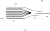
FIG. 2 is a cross-sectional view of a region A ofFIG. 1 . -
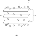
FIG. 3 is a conceptual perspective view of a region B ofFIG. 2 . -
FIG. 4 is a conceptual partial perspective view illustrating an overcharging process in the method for regenerating the cell according to an embodiment of the present invention. -
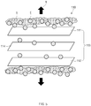
FIG. 5 is a conceptual partial perspective view illustrating a negative pressure processing process in the method for regenerating the cell according to an embodiment of the present invention. -
FIG. 6 is an conceptual projective view illustrating an ultrasonic wave processing process in the method for regenerating the cell according to an embodiment of the present invention. -
FIG. 7 is a conceptual partial perspective view illustrating the ultrasonic wave processing process in the method for regenerating the cell according to an embodiment of the present invention. -
FIG. 8 is a conceptual partial perspective view illustrating a positive pressure processing process in a positive and negative pressure processing process of the method for regenerating the cell according to an embodiment of the present invention. -
FIG. 9 is a conceptual partial perspective view illustrating a negative pressure processing process in the positive and negative pressure processing process of the method for regenerating the cell according to an embodiment of the present invention. -
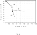
FIG. 10 is a graph illustrating a capacity retention rate of a cell that is revived through the method for regenerating the cell according to an embodiment of the present invention. -
FIG. 11 is a conceptual partial perspective view illustrating a positive pressure processing process in a positive and negative pressure processing process of a method for regenerating a cell according to another embodiment of the present invention. - The objectives, specific advantages, and novel features of the present invention will become more apparent from the following detailed description taken in conjunction with the accompanying drawings. It should be noted that the reference numerals are added to the components of the drawings in the present specification with the same numerals as possible, even if they are illustrated in other drawings. Also, the present invention may be embodied in different forms and should not be construed as limited to the embodiments set forth herein. In the following description of the present invention, the detailed descriptions of related arts which may unnecessarily obscure the gist of the present invention will be omitted.
-
FIG. 1 is a view of a lithium secondary battery applied to a method for regenerating a cell according to an embodiment of the present invention,FIG. 2 is a cross-sectional view of a region A ofFIG. 1 , andFIG. 3 is a conceptual perspective view of a region B ofFIG. 2 . Here,FIG. 2 is a conceptual view illustrating a cell by taking the region A ofFIG. 1 along a longitudinal direction of the cell. - Referring to
FIGS. 1 to 3 , a method for regenerating a cell according to an embodiment of the present invention comprises a negative pressure processing process of applying a negative pressure N to acell 100 to allow a gas G disposed betweenelectrodes 113 to the outside of anelectrode assembly 110 and an ultrasonic wave processing process of stimulating thecell 100 by using ultrasonic waves to allow an electrolyte E disposed outside theelectrode assembly 110 to move between theelectrodes 113. - Also, the method for regenerating the cell according to an embodiment of the present invention may further comprise an overcharging process of overcharging the
cell 100 before the negative pressure processing process and a positive and negative pressure processing process of repeatedly applying a positive pressure and a negative pressure after the ultrasonic wave processing process. - Hereinafter, the method for regenerating the cell according to an embodiment of the present invention will be described in more detail with reference to
FIGS. 1 to 10 . - Referring to
FIGS. 1 to 3 , thecell 100 applied to the method for regenerating the cell according to an embodiment of the present invention comprises theelectrode assembly 110, the electrolyte E, and abattery case 120 accommodating theelectrode assembly 110 and the electrolyte E. Here, thecell 100 applied to the method for regenerating the cell according to an embodiment of the present invention may further comprise anelectrode lead 130 electrically connected to theelectrode assembly 110. - The
electrode assembly 110 may be a chargeable and dischargeable power generation element and have a structure in which anelectrode 113 and aseparator 114 are combined and alternately stacked. Also, theelectrode assembly 110 may further comprise anelectrode tab 115 electrically connected to theelectrode 113 to protrude to the outside of theelectrode assembly 110. - The
electrode 113 may comprise apositive electrode 111 and anegative electrode 112. Here, theelectrode assembly 110 may have a structure in which thepositive electrode 111/theseparator 114/thenegative electrode 112 are alternately stacked. - The
positive electrode 111 may comprise a positive electrode collector (not shown) and a positive electrode active material (not shown) applied to the positive electrode collector, and thenegative electrode 112 may comprise a negative electrode collector (not shown) and a negative electrode active material (not shown) applied to the negative electrode collector. - For example, the positive electrode collector may be provided as foil made of an aluminum (Al) material.
- The positive electrode active material may comprise lithium manganese oxide, lithium cobalt oxide, lithium nickel oxide, lithium iron phosphate, or a compound containing at least one of these and mixtures thereof.
- For another example, the positive electrode active material may comprise a High Ni-based positive electrode material. Here, the High Ni-based positive electrode material may comprise one or more of a LiNiMnCoO-based material, a LiNiCoAl-based material, and a LiMiMnCoAl-based material.
- For example, the negative electrode collector may be provided as foil made of a copper (Cu) or nickel (Ni) material.
- For example, the negative electrode active material may be made of a material comprising synthetic graphite.
- For another example, the negative electrode active material may comprise lithium a metal, a lithium alloy, carbon, petroleum coke, activated carbon, graphite, a silicon compound, a tin compound, a titanium compound, or an alloy thereof.
- The
separator 114 is made of an insulation material to electrically insulate thepositive electrode 111 from thenegative electrode 112. Here, theseparator 114 may be made of, for example, a polyolefin-based resin film such as polyethylene or polypropylene having micropores. - For example, the electrolyte may comprise a non-aqueous electrolyte and a lithium salt as a non-aqueous electrolyte containing lithium.
- For example, the non-aqueous electrolyte may comprise an aprotic organic solvent such as N-methyl-2-pyrrolidone, propylene carbonate, ethylene carbonate, butylene carbonate, dimethyl carbonate, diethyle carbonate, gamma-butyrolacton, 1,2-dimethoxy ethane, tetrahydroxy franc, 2-methyl tetrahydrofuran, dimethyl sulfoxide, 1,3-dioxolane, formamide, dimethyl formamide, dioxolane, acetonitrile, nitromethane, methyl formate, methyl acetate, phosphoric acid tri-ester, trimethoxy methane, dioxolane derivatives, sulfolan, methyl sulfolan, 1,3-dimethyl-2-imidazolidinone, a propylene carbonate derivative, a tetrahydrofuran derivative, ether, methyl propionate, and ethyl propionate.
- Here, the lithium salt is easily dissolved in the non-aqueous electrolyte. For example, the lithium salt may comprise LiCl, LiBr, LiI, LiClO4, LiBF4, LiB10Cl10, LiPF6, LiCF3SO3, LiCF3CO2, LiAsF6, LiSbF6, LiAlCl4, CH3SO3Li, CF3SO3Li, (CF3SO2)2NLi, chloroborane lithium, lower aliphatic carboxylic acid lithium, 4phenyl lithium borate, or an imide.
- In some cases, the lithium salt may comprise an organic solid electrolyte or an inorganic solid electrolyte.
- For example, the organic solid electrolyte may comprise a copolymer comprising a polyethylene derivative, a polyethylene oxide derivative, a polypropylene oxide derivative, a phosphoric acid ester polymer, poly agitation lysine, polyester sulfide, polyvinyl alcohol, poly vinylidene fluoride, or an ionic disintegrator.
- For example, the inorganic solid electrolyte may comprise a Li-based nitride such as Li3N, LiI, Li5NI2, Li3N-Lil-LiOH, LiSiO4, LiSiO4-LiI-LiOH, Li2SiS3, Li4SiO4, Li4SiO4-Lil-LiOH, and Li3PO4-Li2S-SiS2, a halide, or a sulfate.
- Further, the following compounds may be added to the non-aqueous electrolyte in order to improve discharge and charge characteristics and flame retardancy. For example, the non-aqueous electrolyte may comprise pyridine, triethyl phosphite, triethanolamine, cyclic ether, ethylenediamine, n-glyme, hexaphosphoric triamide, a nitrobenzene derivative, sulfur, a quinone-imine dye, N-substituted oxazolidinone, N,N-substituted imidazolidine, ethylene glycol dialkyl ether, an ammonium salt, pyrrole, 2-methoxyethanol, and aluminum trichloride. In some cases, in order to give incombustibility to the electrolyte, the electrolyte may further comprise a halogen-containing solvent such as carbon tetrachloride and ethylene trifluoride. Further, in order to improve high-temperature storage characteristics, the electrolyte may comprise carbon dioxide gas.
-
FIG. 4 is a conceptual partial perspective view illustrating an overcharging process in the method for regenerating the cell according to an embodiment of the present invention. - Referring to
FIGS. 2 and4 , in an overcharging process, thecell 100 may be overcharged before the negative pressure processing process to reduce a concentration of the electrolyte E disposed inside theelectrode assembly 110. - In more detail, in the overcharging process, the
cell 100 may be overcharged to allow the electrolyte E adjacent to theelectrode 113 to be formed as a gas G through side reaction. Thus, as the concentration of the electrolyte E disposed inside theelectrode assembly 110 is reduced, the electrolyte E disposed outside theelectrode assembly 110 may move to the inside of theelectrode assembly 110 by an osmotic pressure. - Here, in the overcharging process, for example, a voltage of 4.3 V or more may be applied to overcharge the
cell 100. In more detail, in the overcharging process, for example, a voltage of 4.3 V to 4.5 V may be applied to overcharge thecell 100. Thus, when an overvoltage exceeding 4.3 V that exceeds a voltage range of 2.2 V to 4.2 V of thegeneral cell 100 is applied, the electrolyte E may be converted into a gas G due to side reaction. - In the overcharging process, for example, the
cell 100 may be rapidly overcharged for 0.1 seconds to 1 second. Thus, when thecell 100 is overcharged, the side reaction may occur first in the electrolyte E disposed on a surface of each of theelectrodes 113. Thus, only the electrolyte E disposed close to theelectrode 113 may be gasified through the rapid overcharging, and the electrolyte E disposed outside theelectrode assembly 110 may not be gasified. -
FIG. 5 is a conceptual partial perspective view illustrating the negative pressure processing process in the method for regenerating the cell according to an embodiment of the present invention. - Referring to
FIGS. 1 ,2 , and5 , in the negative pressure processing process, a negative pressure N may be applied to thecell 100 to the gas G disposed between theelectrodes 113 may move to the outside of theelectrode assembly 110. Here, in the negative pressure processing process, the gas G disposed inside theelectrode assembly 110, which is generated through the overcharging process or generated while thecell 100 is degraded due the continuous charging/discharging thereof, may move to the outside of theelectrode assembly 110. Thus, the gas G disposed inside theelectrode assembly 110 may move to the outside of theelectrode assembly 110 so that the electrolyte E disposed outside theelectrode assembly 110 easily moves to the inside of theelectrode assembly 110. For example, a gas absorbent (not shown) may be provided in thecell 100 to absorb the gas G that moves to the outside of theelectrode assembly 110. - Also, in the negative pressure processing process, after the
cell 100 is accommodated in a chamber C, the inside of the chamber C may be vacuumized to apply the negative pressure N to thecell 100. Here, for example, a vacuum pump (not shown) may be connected to the chamber C to vacuumize the inside of the chamber C through the vacuum pump. - Furthermore, in the negative pressure processing process, the inside of the chamber C may be vacuumized so that the inside of the chamber C is in a pressure state of - 90 Kpa to -100 Kpa.
-
FIG. 6 is an conceptual projective view illustrating an ultrasonic wave processing process in the method for regenerating the cell according to an embodiment of the present invention, andFIG. 7 is a conceptual partial perspective view illustrating the ultrasonic wave processing process in the method for regenerating the cell according to an embodiment of the present invention. - Referring to
FIGS. 6 and7 , in the ultrasonic wave processing process, thecell 100 may be stimulated by ultrasonic waves S to allow the electrolyte E disposed outside theelectrode assembly 110 to move between theelectrode 113. Here, in the ultrasonic wave processing process, ultrasonic waves S having intensities of 40% to 80%, 20 kHz to 30 kHz, and 20 W/cm2 may be applied to thecell 100. - Also, in the ultrasonic wave processing process, the
cell 100 may be stimulated by the ultrasonic waves S in a state in which thecell 100 is immersed in aninsulation liquid 11 made of a material having no electrical conductivity. Here, theinsulation liquid 11 may comprise ethanol. Here, theinsulation liquid 11 may be made of, for example, an ethanol covalent bonding compound having no ions that are capable of transporting electricity. - Furthermore, in the ultrasonic wave processing process, the
electrode lead 130 may be sealed with aninsulation tape 30, and thecell 100 may be immersed in abath 10 in which ethanol is accommodated. - Thus, when the ultrasonic wave processing is performed on the
cell 100, an occurrence of short circuit due to a solvent may be prevented. - In the ultrasonic wave processing process, an end of an
ultrasonic generator 20 may be immersed in thebath 10 containing ethanol to generate ultrasonic waves S and thereby to stimulate thecell 100. - Also, in the ultrasonic wave processing process, when the
cell 100 is stimulated by the ultrasonic waves S, a positive pressure may be applied to thecell 100. Thus, the electrolyte E disposed outside theelectrode assembly 110 may more effectively move between theelectrodes 113. -
FIG. 8 is a conceptual partial perspective view illustrating a positive pressure processing process in a positive and negative pressure processing process of the method for regenerating the cell according to an embodiment of the present invention, andFIG. 9 is a conceptual partial perspective view illustrating a negative pressure processing process in the positive and negative pressure processing process of the method for regenerating the cell according to an embodiment of the present invention. - Referring to
FIGS. 1 ,2 ,8 , and9 , in the positive and negative pressure processing process, the positive pressure P and the negative pressure N may be repeatedly applied to thecell 100 to allow the electrolyte E disposed outside theelectrode assembly 110 to move between theelectrodes 113. - Also, in the positive and negative pressure processing process, after the
cell 100 is accommodated in the chamber C, the positive pressure P may be applied to thecell 100 by making the inside of the chamber C into a state of the positive pressure P (seeFIG. 8 ), and the negative pressure N may be applied to thecell 100 by making the inside of the chamber C into a state of the negative pressure P (seeFIG. 9 ) . - Here, a vacuum pump and a gas pressurizing pump (not shown) may be connected to the chamber C to generate the positive pressure P and the negative pressure N inside the chamber C through the vacuum pump and the gas pressurizing pump.
- Here, in the positive and negative pressure processing process, a pressure of 90 kPa to 100 kPa as the positive pressure P may be applied to the
cell 100, and a pressure of -90 kPa to -100 kPa as the negative pressure N may be applied to thecell 100. - In the above-described method for regenerating the cell according to an embodiment, the electrolyte E disposed outside the
electrode assembly 110 may move to the inside of theelectrode assembly 110. Thus, the charging/discharging of thecell 100 may be repeated so that an amount of lithium ions inside theelectrode assembly 110, in which the lithium ions are insufficient, increases. That is, the lithium ions contained in the electrolyte E disposed outside theelectrode assembly 110 may move to the inside of theelectrode assembly 110, and thus, the lithium ions may be supplied to theelectrode assembly 110, in which the lithium ions are insufficient, to increase in capacity of thecell 100. Also, thecell 100, which decreases in capacity, may be regenerated without breaking and damaging thecell 100. -
FIG. 10 is a graph illustrating a capacity retention rate of the cell that is revived through the method for regenerating the cell according to an embodiment of the present invention. - In the graph shown in
FIG. 10 , an initial cell C1, a cell C2 that is regenerated through the method for regenerating the cell according to an embodiment of the present invention, and a cell C3 that has not been regenerated are illustrated. - Here, in
FIG. 10 , a horizontal axis represents the number of cycles, and a vertical axis represents a 1C (coulomb) capacity retention rate of the cell. - Referring to the graph shown in
FIG. 10 , it is seen that the initial cell C1 decreases in capacity retention rate as the cycle progresses. - Here, it is seen that the initial cell C1 rapidly decreases in capacity retention rate to be degraded after 400 cycles. That is, it is seen that the cell C3, which has not been regenerated, is degraded after 500 cycles because the capacity retention rate remarkably decreases to 25% or less.
- However, it is seen that the cell C2, which is regenerated through the method for regenerating the cell according to an embodiment of the present invention, is maintained to a capacity retention rate of 50% or more until reaching 1,000 cycles. That is, it is seen through the graph shown in
FIG. 10 that the capacity of the cell C2, which is regenerated through the method for regenerating the cell according to an embodiment of the present invention, is significantly improved. -
FIG. 11 is a conceptual partial perspective view illustrating a positive pressure processing process in a positive and negative pressure processing process of a method for regenerating a cell according to another embodiment of the present invention. - Hereinafter, a method for regenerating a cell according to another embodiment of the present invention will be described with reference to
FIG. 11 . - Referring to
FIG. 11 , the method for reproducing the cell according to another embodiment of the present invention is different from the method for reproducing the cell according to the foregoing embodiment in a positive pressure processing process of the positive and negative pressure processing process. Thus, contents of this embodiment, which are duplicated with those according to the forgoing embodiment, will be briefly described, and also, differences therebetween will be mainly described. - In the positive and negative pressure processing process of the method for regenerating the cell according to another embodiment of the present invention, a positive pressure P and a negative pressure N may be repeatedly applied to a
cell 100 to allow an electrolyte E disposed outside anelectrode assembly 110 to move betweenelectrodes 113. Here, when the positive pressure P is applied to thecell 100, thecell 100 may be stimulated by ultrasonic waves S. - Thus, the electrolyte E disposed outside the
electrode assembly 110 may more smoothly move to the inside of theelectrode assembly 110. - Here, a positive pressure P of 90 kPa to 100 kPa may be applied to the
cell 100, and thecell 100 may be stimulated by ultrasonic waves having an intensity of 40% to 80% and a frequency of 20 kHz to 30 kHz and 20 W/cm2. - In the positive and negative pressure processing process, the
cell 100 may be accommodated in a chamber C, and then, the positive pressure P may be applied to thecell 100 by making the inside of the chamber C into a state of the positive pressure P (seeFIG. 1 ). - While the present invention has been particularly shown and described with reference to exemplary embodiments thereof, it is to be understood that the scope of the present invention is not limited to the method for regenerating the cell according to the present invention. It will be understood by those of ordinary skill in the art that various changes in form and details may be made therein without departing from the spirit and scope of the invention.
- Furthermore, the scope of protection of the present invention will be clarified by the appended claims.
Claims (15)
- A method for regenerating a cell comprising an electrode assembly, in which electrodes and a separator are alternately combined with each other, an electrolyte, and a battery case accommodating the electrode assembly and the electrolyte, the method comprising:a negative pressure processing process in which a negative pressure is applied to the cell to allow a gas disposed between the electrodes to move to the outside the electrode assembly; andan ultrasonic wave processing process in which the cell is stimulated by ultrasonic waves to allow the electrolyte disposed outside the electrode assembly to move between the electrodes.
- The method of claim 1, further comprising, before the negative pressure processing process, an overcharging process in which the cell is overcharged to allow the electrolyte adjacent to the electrodes to generate the gas through side reaction thereof, and as a concentration of the electrolyte disposed inside the electrode assembly is reduced, the electrolyte disposed outside the electrode assembly moves to the inside of the electrode assembly by an osmotic pressure.
- The method of claim 2, wherein, in the overcharging process, a voltage of 4.3 V or more is applied to the cell to overcharge the cell.
- The method of claim 3, wherein, in the overcharging process, a voltage of 4.3 V to 4.5 V is applied to the cell to overcharge the cell.
- The method of any one of claims 1 to 4, wherein, in the overcharging process, the cell is overcharged for 0.1 seconds to 1 second.
- The method of any one of claims 1 to 4, further comprising, after the ultrasonic wave processing process, a positive and negative pressure processing process in which a positive pressure and the negative pressure are repeatedly applied to the cell to allow the electrolyte disposed outside the electrode assembly to move between the electrodes.
- The method of claim 6, wherein, in the positive and negative pressure processing process, after the cell is accommodated in a chamber, the positive pressure is applied to the cell by making the inside of the chamber into a positive pressure state, and the negative pressure is applied to the cell by making the inside of the chamber into a negative pressure state.
- The method of claim 6, wherein, in the positive and negative pressure processing process, when the positive pressure is applied to the cell, the cell is stimulated by the ultrasonic waves.
- The method of claim 1, wherein, in the negative pressure processing process, after the cell is accommodated in a chamber, the inside of the chamber is vacuumized to apply the negative pressure to the cell.
- The method of claim 9, wherein, in the negative pressure processing process, the inside of the chamber becomes a pressure state of -90 kPa to -100 kPa.
- The method of claim 1, wherein, in the ultrasonic wave processing process, the cell is stimulated by ultrasonic waves in a state in which the cell is immersed in an insulation liquid.
- The method of claim 11, wherein the insulation liquid comprises ethanol.
- The method of claim 12, wherein the cell comprises an electrode lead electrically connected to the electrode assembly so that a portion of the electrode lead protrudes to the outside of the battery case, and
in the ultrasonic wave processing process, the electrode lead is sealed with an insulation tape, and the cell is immersed in a bath in which ethanol is accommodated. - The method of claim 1, wherein, in the ultrasonic wave processing process, ultrasonic waves of 20 kHz to 30 kHz are applied to the cell.
- The method of claim 1, wherein, in the ultrasonic wave processing process, when the cell is stimulated by the ultrasonic waves, a positive pressure is applied to the cell.
Applications Claiming Priority (2)
| Application Number | Priority Date | Filing Date | Title |
|---|---|---|---|
| KR1020170095184A KR102168568B1 (en) | 2017-07-27 | 2017-07-27 | Regnerative method of cell |
| PCT/KR2018/007826 WO2019022409A1 (en) | 2017-07-27 | 2018-07-10 | Cell recycling method |
Publications (3)
| Publication Number | Publication Date |
|---|---|
| EP3512031A1 true EP3512031A1 (en) | 2019-07-17 |
| EP3512031A4 EP3512031A4 (en) | 2020-01-15 |
| EP3512031B1 EP3512031B1 (en) | 2023-04-19 |
Family
ID=65041299
Family Applications (1)
| Application Number | Title | Priority Date | Filing Date |
|---|---|---|---|
| EP18839184.1A Active EP3512031B1 (en) | 2017-07-27 | 2018-07-10 | Method for regenerating electrochemical cells |
Country Status (8)
| Country | Link |
|---|---|
| US (1) | US11387499B2 (en) |
| EP (1) | EP3512031B1 (en) |
| KR (1) | KR102168568B1 (en) |
| CN (1) | CN109923729B (en) |
| ES (1) | ES2945468T3 (en) |
| HU (1) | HUE062071T2 (en) |
| PL (1) | PL3512031T3 (en) |
| WO (1) | WO2019022409A1 (en) |
Cited By (1)
| Publication number | Priority date | Publication date | Assignee | Title |
|---|---|---|---|---|
| CN112054265A (en) * | 2020-09-30 | 2020-12-08 | 合肥国轩高科动力能源有限公司 | Method for recycling and reusing anode material of waste ternary lithium ion battery |
Families Citing this family (1)
| Publication number | Priority date | Publication date | Assignee | Title |
|---|---|---|---|---|
| CN113140818B (en) * | 2021-02-27 | 2022-09-06 | 浙江锋锂新能源科技有限公司 | Lithium metal battery pretreatment process and lithium metal battery |
Family Cites Families (23)
| Publication number | Priority date | Publication date | Assignee | Title |
|---|---|---|---|---|
| GB8600894D0 (en) * | 1986-01-15 | 1986-02-19 | Atomic Energy Authority Uk | Electrochemical cells |
| US6465121B1 (en) * | 2000-08-30 | 2002-10-15 | Lev M. Dawson | Method for distributing electrolyte in batteries |
| JP2002190329A (en) | 2000-12-21 | 2002-07-05 | Tomotaka Marui | Method and device for lead storage battery regeneration |
| CN1248354C (en) * | 2003-12-10 | 2006-03-29 | 北京理工大学 | A novel method used for non destructive battery regeneration |
| CN101030663A (en) * | 2007-04-06 | 2007-09-05 | 北京理工大学 | Method for recovering and regenerating refused battery critical material |
| KR100904641B1 (en) * | 2007-09-19 | 2009-06-25 | 주식회사 한건시스템 | Regenerating method of waste storage battery |
| KR20100130685A (en) * | 2009-06-04 | 2010-12-14 | (주)하인텍 | Ultrasonic pulse charge apparatus and disuse battery revival method thereof |
| KR101201808B1 (en) * | 2010-06-03 | 2012-11-15 | 삼성에스디아이 주식회사 | Rechargeable battery and method of injecting electrolyte thereinto |
| JP5341823B2 (en) | 2010-06-07 | 2013-11-13 | トヨタ自動車株式会社 | Lithium ion secondary battery degradation judgment system and degradation judgment method |
| KR101334623B1 (en) * | 2010-12-02 | 2013-11-29 | 주식회사 엘지화학 | Degassing Method of Secondary Battery Using Centrifugal Force |
| CN102983378A (en) * | 2011-09-07 | 2013-03-20 | 徐辛 | Method and device for carrying out charging and discharging upon storage batteries by using ultrasonic waves |
| CN102340034A (en) * | 2011-09-29 | 2012-02-01 | 深圳市创明电池技术有限公司 | Method and equipment for activating lithium ion battery |
| KR101528001B1 (en) | 2012-06-22 | 2015-06-10 | 주식회사 엘지화학 | Electrode assembly, manufacture thereof, and secondary batteries including same |
| KR20140057696A (en) * | 2012-10-25 | 2014-05-14 | 황해룡 | Insulation liquid circulation cooling type secondary battery |
| CN107112567B (en) | 2014-12-18 | 2020-05-12 | 株式会社Lg化学 | Assembly for regenerating electrolyte of flow battery and method for regenerating electrolyte of flow battery using same |
| KR101535051B1 (en) * | 2015-01-08 | 2015-07-08 | 임형진 | Process for recycling waste battery |
| KR101663026B1 (en) | 2015-06-04 | 2016-10-06 | 서울시립대학교 산학협력단 | Capacity restoration method of lithium secondary battery |
| JP6517092B2 (en) | 2015-06-26 | 2019-05-22 | 有限会社オーエイチケー研究所 | Battery charger, battery diagnostic device using the same, and battery regenerator |
| JP6270059B2 (en) | 2015-08-04 | 2018-01-31 | トヨタ自動車株式会社 | Performance degradation recovery method for lithium ion secondary battery |
| WO2017034052A1 (en) * | 2015-08-26 | 2017-03-02 | (주)턴투 | Battery recovery method |
| JP6504012B2 (en) | 2015-10-09 | 2019-04-24 | 株式会社デンソー | Assembled battery |
| CN105576314A (en) | 2015-12-18 | 2016-05-11 | 山东精工电子科技有限公司 | Recycling method of positive electrode piece of lithium ion battery |
| KR101753807B1 (en) * | 2017-03-27 | 2017-07-04 | 김상준 | Device for battery performance recovery |
-
2017
- 2017-07-27 KR KR1020170095184A patent/KR102168568B1/en active IP Right Grant
-
2018
- 2018-07-10 HU HUE18839184A patent/HUE062071T2/en unknown
- 2018-07-10 ES ES18839184T patent/ES2945468T3/en active Active
- 2018-07-10 EP EP18839184.1A patent/EP3512031B1/en active Active
- 2018-07-10 WO PCT/KR2018/007826 patent/WO2019022409A1/en unknown
- 2018-07-10 US US16/341,627 patent/US11387499B2/en active Active
- 2018-07-10 CN CN201880004046.7A patent/CN109923729B/en active Active
- 2018-07-10 PL PL18839184.1T patent/PL3512031T3/en unknown
Cited By (1)
| Publication number | Priority date | Publication date | Assignee | Title |
|---|---|---|---|---|
| CN112054265A (en) * | 2020-09-30 | 2020-12-08 | 合肥国轩高科动力能源有限公司 | Method for recycling and reusing anode material of waste ternary lithium ion battery |
Also Published As
| Publication number | Publication date |
|---|---|
| US20210313628A1 (en) | 2021-10-07 |
| CN109923729B (en) | 2022-02-22 |
| KR20190012359A (en) | 2019-02-11 |
| KR102168568B1 (en) | 2020-10-21 |
| PL3512031T3 (en) | 2023-07-10 |
| CN109923729A (en) | 2019-06-21 |
| US11387499B2 (en) | 2022-07-12 |
| EP3512031B1 (en) | 2023-04-19 |
| EP3512031A4 (en) | 2020-01-15 |
| WO2019022409A1 (en) | 2019-01-31 |
| ES2945468T3 (en) | 2023-07-03 |
| HUE062071T2 (en) | 2023-09-28 |
Similar Documents
| Publication | Publication Date | Title |
|---|---|---|
| US10770694B2 (en) | Prismatic battery cell having two or more case members | |
| US10340498B2 (en) | Electrode assembly with tab-lead coupler and method for manufacturing the same | |
| US10505230B2 (en) | Hybrid electrode assembly of stair-like structure | |
| KR101787254B1 (en) | Secondary battery | |
| KR101636449B1 (en) | Secondary Battery Employed with Seal Tape for Preventing Power Failure of Electrode Assembly | |
| KR20140017743A (en) | Secondary battery with improved vibration resistance | |
| US20160087252A1 (en) | Method of manufacturing pouch-shaped battery cell having sealed portion insulated with curable material | |
| EP3512031B1 (en) | Method for regenerating electrochemical cells | |
| JP2018106903A (en) | Lithium ion secondary battery | |
| KR102070907B1 (en) | Battery Cell Comprising Non-coating Portion Accommodating Gas Generated During Charge and Discharge | |
| KR20150038932A (en) | Method of Secondary Battery Using Protective Case | |
| US11362373B2 (en) | Method for regenerating lithium secondary battery | |
| KR101307772B1 (en) | Method for Manufacturing Secondary Battery and Secondary Battery Manufactured thereby | |
| KR20160066202A (en) | Battery Cell Having Fixing Member Installed on Outer Surface of Battery Case and Method for Manufacturing the Same | |
| JP2020202039A (en) | Nonaqueous electrolyte secondary battery | |
| CN114583244B (en) | Lithium ion secondary battery | |
| US11050047B2 (en) | Method for manufacturing secondary battery using lithium metal as negative electrode | |
| JP6635320B2 (en) | Non-aqueous electrolyte secondary battery | |
| KR101717154B1 (en) | Manufacturing Method of the Battery Cell Applied Curing Material and Manufacturing Device | |
| US20220294015A1 (en) | Nonaqueous electrolyte secondary battery | |
| JP6963731B2 (en) | Lithium ion secondary battery | |
| JP6731155B2 (en) | Non-aqueous electrolyte secondary battery | |
| KR101814792B1 (en) | Electrode Assembly Comprising Separate film with Inorganic Coating Portion and Non-coating Portion and Battery Cell Comprising the Same | |
| JP2017050156A (en) | Nonaqueous electrolyte secondary battery |
Legal Events
| Date | Code | Title | Description |
|---|---|---|---|
| STAA | Information on the status of an ep patent application or granted ep patent |
Free format text: STATUS: THE INTERNATIONAL PUBLICATION HAS BEEN MADE |
|
| PUAI | Public reference made under article 153(3) epc to a published international application that has entered the european phase |
Free format text: ORIGINAL CODE: 0009012 |
|
| STAA | Information on the status of an ep patent application or granted ep patent |
Free format text: STATUS: REQUEST FOR EXAMINATION WAS MADE |
|
| 17P | Request for examination filed |
Effective date: 20190408 |
|
| AK | Designated contracting states |
Kind code of ref document: A1 Designated state(s): AL AT BE BG CH CY CZ DE DK EE ES FI FR GB GR HR HU IE IS IT LI LT LU LV MC MK MT NL NO PL PT RO RS SE SI SK SM TR |
|
| AX | Request for extension of the european patent |
Extension state: BA ME |
|
| A4 | Supplementary search report drawn up and despatched |
Effective date: 20191212 |
|
| RIC1 | Information provided on ipc code assigned before grant |
Ipc: H01M 10/52 20060101ALI20191206BHEP Ipc: H01M 10/42 20060101AFI20191206BHEP Ipc: H01M 10/44 20060101ALI20191206BHEP Ipc: H01M 10/052 20100101ALI20191206BHEP |
|
| DAV | Request for validation of the european patent (deleted) | ||
| DAX | Request for extension of the european patent (deleted) | ||
| RAP1 | Party data changed (applicant data changed or rights of an application transferred) |
Owner name: LG ENERGY SOLUTION LTD. |
|
| RAP3 | Party data changed (applicant data changed or rights of an application transferred) |
Owner name: LG ENERGY SOLUTION, LTD. |
|
| GRAP | Despatch of communication of intention to grant a patent |
Free format text: ORIGINAL CODE: EPIDOSNIGR1 |
|
| STAA | Information on the status of an ep patent application or granted ep patent |
Free format text: STATUS: GRANT OF PATENT IS INTENDED |
|
| INTG | Intention to grant announced |
Effective date: 20221117 |
|
| GRAS | Grant fee paid |
Free format text: ORIGINAL CODE: EPIDOSNIGR3 |
|
| GRAA | (expected) grant |
Free format text: ORIGINAL CODE: 0009210 |
|
| STAA | Information on the status of an ep patent application or granted ep patent |
Free format text: STATUS: THE PATENT HAS BEEN GRANTED |
|
| AK | Designated contracting states |
Kind code of ref document: B1 Designated state(s): AL AT BE BG CH CY CZ DE DK EE ES FI FR GB GR HR HU IE IS IT LI LT LU LV MC MK MT NL NO PL PT RO RS SE SI SK SM TR |
|
| REG | Reference to a national code |
Ref country code: GB Ref legal event code: FG4D |
|
| REG | Reference to a national code |
Ref country code: CH Ref legal event code: EP |
|
| REG | Reference to a national code |
Ref country code: DE Ref legal event code: R096 Ref document number: 602018048703 Country of ref document: DE |
|
| REG | Reference to a national code |
Ref country code: IE Ref legal event code: FG4D |
|
| REG | Reference to a national code |
Ref country code: AT Ref legal event code: REF Ref document number: 1561881 Country of ref document: AT Kind code of ref document: T Effective date: 20230515 |
|
| REG | Reference to a national code |
Ref country code: SE Ref legal event code: TRGR |
|
| REG | Reference to a national code |
Ref country code: ES Ref legal event code: FG2A Ref document number: 2945468 Country of ref document: ES Kind code of ref document: T3 Effective date: 20230703 |
|
| PGFP | Annual fee paid to national office [announced via postgrant information from national office to epo] |
Ref country code: FR Payment date: 20230621 Year of fee payment: 6 |
|
| REG | Reference to a national code |
Ref country code: LT Ref legal event code: MG9D |
|
| REG | Reference to a national code |
Ref country code: NL Ref legal event code: MP Effective date: 20230419 |
|
| PGFP | Annual fee paid to national office [announced via postgrant information from national office to epo] |
Ref country code: SE Payment date: 20230621 Year of fee payment: 6 Ref country code: PL Payment date: 20230627 Year of fee payment: 6 |
|
| REG | Reference to a national code |
Ref country code: AT Ref legal event code: MK05 Ref document number: 1561881 Country of ref document: AT Kind code of ref document: T Effective date: 20230419 |
|
| REG | Reference to a national code |
Ref country code: HU Ref legal event code: AG4A Ref document number: E062071 Country of ref document: HU |
|
| PG25 | Lapsed in a contracting state [announced via postgrant information from national office to epo] |
Ref country code: NL Free format text: LAPSE BECAUSE OF FAILURE TO SUBMIT A TRANSLATION OF THE DESCRIPTION OR TO PAY THE FEE WITHIN THE PRESCRIBED TIME-LIMIT Effective date: 20230419 |
|
| PG25 | Lapsed in a contracting state [announced via postgrant information from national office to epo] |
Ref country code: PT Free format text: LAPSE BECAUSE OF FAILURE TO SUBMIT A TRANSLATION OF THE DESCRIPTION OR TO PAY THE FEE WITHIN THE PRESCRIBED TIME-LIMIT Effective date: 20230821 Ref country code: NO Free format text: LAPSE BECAUSE OF FAILURE TO SUBMIT A TRANSLATION OF THE DESCRIPTION OR TO PAY THE FEE WITHIN THE PRESCRIBED TIME-LIMIT Effective date: 20230719 Ref country code: AT Free format text: LAPSE BECAUSE OF FAILURE TO SUBMIT A TRANSLATION OF THE DESCRIPTION OR TO PAY THE FEE WITHIN THE PRESCRIBED TIME-LIMIT Effective date: 20230419 |
|
| PGFP | Annual fee paid to national office [announced via postgrant information from national office to epo] |
Ref country code: GB Payment date: 20230620 Year of fee payment: 6 Ref country code: ES Payment date: 20230814 Year of fee payment: 6 |
|
| PG25 | Lapsed in a contracting state [announced via postgrant information from national office to epo] |
Ref country code: RS Free format text: LAPSE BECAUSE OF FAILURE TO SUBMIT A TRANSLATION OF THE DESCRIPTION OR TO PAY THE FEE WITHIN THE PRESCRIBED TIME-LIMIT Effective date: 20230419 Ref country code: LV Free format text: LAPSE BECAUSE OF FAILURE TO SUBMIT A TRANSLATION OF THE DESCRIPTION OR TO PAY THE FEE WITHIN THE PRESCRIBED TIME-LIMIT Effective date: 20230419 Ref country code: LT Free format text: LAPSE BECAUSE OF FAILURE TO SUBMIT A TRANSLATION OF THE DESCRIPTION OR TO PAY THE FEE WITHIN THE PRESCRIBED TIME-LIMIT Effective date: 20230419 Ref country code: IS Free format text: LAPSE BECAUSE OF FAILURE TO SUBMIT A TRANSLATION OF THE DESCRIPTION OR TO PAY THE FEE WITHIN THE PRESCRIBED TIME-LIMIT Effective date: 20230819 Ref country code: HR Free format text: LAPSE BECAUSE OF FAILURE TO SUBMIT A TRANSLATION OF THE DESCRIPTION OR TO PAY THE FEE WITHIN THE PRESCRIBED TIME-LIMIT Effective date: 20230419 Ref country code: GR Free format text: LAPSE BECAUSE OF FAILURE TO SUBMIT A TRANSLATION OF THE DESCRIPTION OR TO PAY THE FEE WITHIN THE PRESCRIBED TIME-LIMIT Effective date: 20230720 Ref country code: AL Free format text: LAPSE BECAUSE OF FAILURE TO SUBMIT A TRANSLATION OF THE DESCRIPTION OR TO PAY THE FEE WITHIN THE PRESCRIBED TIME-LIMIT Effective date: 20230419 |
|
| PGFP | Annual fee paid to national office [announced via postgrant information from national office to epo] |
Ref country code: HU Payment date: 20230717 Year of fee payment: 6 Ref country code: DE Payment date: 20230620 Year of fee payment: 6 |
|
| PG25 | Lapsed in a contracting state [announced via postgrant information from national office to epo] |
Ref country code: FI Free format text: LAPSE BECAUSE OF FAILURE TO SUBMIT A TRANSLATION OF THE DESCRIPTION OR TO PAY THE FEE WITHIN THE PRESCRIBED TIME-LIMIT Effective date: 20230419 |
|
| PG25 | Lapsed in a contracting state [announced via postgrant information from national office to epo] |
Ref country code: SK Free format text: LAPSE BECAUSE OF FAILURE TO SUBMIT A TRANSLATION OF THE DESCRIPTION OR TO PAY THE FEE WITHIN THE PRESCRIBED TIME-LIMIT Effective date: 20230419 |
|
| REG | Reference to a national code |
Ref country code: DE Ref legal event code: R097 Ref document number: 602018048703 Country of ref document: DE |
|
| PG25 | Lapsed in a contracting state [announced via postgrant information from national office to epo] |
Ref country code: SM Free format text: LAPSE BECAUSE OF FAILURE TO SUBMIT A TRANSLATION OF THE DESCRIPTION OR TO PAY THE FEE WITHIN THE PRESCRIBED TIME-LIMIT Effective date: 20230419 Ref country code: SK Free format text: LAPSE BECAUSE OF FAILURE TO SUBMIT A TRANSLATION OF THE DESCRIPTION OR TO PAY THE FEE WITHIN THE PRESCRIBED TIME-LIMIT Effective date: 20230419 Ref country code: RO Free format text: LAPSE BECAUSE OF FAILURE TO SUBMIT A TRANSLATION OF THE DESCRIPTION OR TO PAY THE FEE WITHIN THE PRESCRIBED TIME-LIMIT Effective date: 20230419 Ref country code: EE Free format text: LAPSE BECAUSE OF FAILURE TO SUBMIT A TRANSLATION OF THE DESCRIPTION OR TO PAY THE FEE WITHIN THE PRESCRIBED TIME-LIMIT Effective date: 20230419 Ref country code: DK Free format text: LAPSE BECAUSE OF FAILURE TO SUBMIT A TRANSLATION OF THE DESCRIPTION OR TO PAY THE FEE WITHIN THE PRESCRIBED TIME-LIMIT Effective date: 20230419 Ref country code: CZ Free format text: LAPSE BECAUSE OF FAILURE TO SUBMIT A TRANSLATION OF THE DESCRIPTION OR TO PAY THE FEE WITHIN THE PRESCRIBED TIME-LIMIT Effective date: 20230419 |
|
| PLBE | No opposition filed within time limit |
Free format text: ORIGINAL CODE: 0009261 |
|
| STAA | Information on the status of an ep patent application or granted ep patent |
Free format text: STATUS: NO OPPOSITION FILED WITHIN TIME LIMIT |
|
| PG25 | Lapsed in a contracting state [announced via postgrant information from national office to epo] |
Ref country code: MC Free format text: LAPSE BECAUSE OF FAILURE TO SUBMIT A TRANSLATION OF THE DESCRIPTION OR TO PAY THE FEE WITHIN THE PRESCRIBED TIME-LIMIT Effective date: 20230419 |
|
| PG25 | Lapsed in a contracting state [announced via postgrant information from national office to epo] |
Ref country code: MC Free format text: LAPSE BECAUSE OF FAILURE TO SUBMIT A TRANSLATION OF THE DESCRIPTION OR TO PAY THE FEE WITHIN THE PRESCRIBED TIME-LIMIT Effective date: 20230419 |
|
| REG | Reference to a national code |
Ref country code: CH Ref legal event code: PL |
|
| REG | Reference to a national code |
Ref country code: BE Ref legal event code: MM Effective date: 20230731 |
|
| PG25 | Lapsed in a contracting state [announced via postgrant information from national office to epo] |
Ref country code: LU Free format text: LAPSE BECAUSE OF NON-PAYMENT OF DUE FEES Effective date: 20230710 |
|
| 26N | No opposition filed |
Effective date: 20240122 |
|
| PG25 | Lapsed in a contracting state [announced via postgrant information from national office to epo] |
Ref country code: LU Free format text: LAPSE BECAUSE OF NON-PAYMENT OF DUE FEES Effective date: 20230710 |
|
| PG25 | Lapsed in a contracting state [announced via postgrant information from national office to epo] |
Ref country code: CH Free format text: LAPSE BECAUSE OF NON-PAYMENT OF DUE FEES Effective date: 20230731 |
|
| PG25 | Lapsed in a contracting state [announced via postgrant information from national office to epo] |
Ref country code: SI Free format text: LAPSE BECAUSE OF FAILURE TO SUBMIT A TRANSLATION OF THE DESCRIPTION OR TO PAY THE FEE WITHIN THE PRESCRIBED TIME-LIMIT Effective date: 20230419 |