EP3512020A1 - Stacked electrode assembly and flexible secondary battery comprising same - Google Patents
Stacked electrode assembly and flexible secondary battery comprising same Download PDFInfo
- Publication number
- EP3512020A1 EP3512020A1 EP17849049.6A EP17849049A EP3512020A1 EP 3512020 A1 EP3512020 A1 EP 3512020A1 EP 17849049 A EP17849049 A EP 17849049A EP 3512020 A1 EP3512020 A1 EP 3512020A1
- Authority
- EP
- European Patent Office
- Prior art keywords
- electrode
- electrode assembly
- stacked
- separator
- patterns
- Prior art date
- Legal status (The legal status is an assumption and is not a legal conclusion. Google has not performed a legal analysis and makes no representation as to the accuracy of the status listed.)
- Granted
Links
Images





Classifications
-
- H—ELECTRICITY
- H01—ELECTRIC ELEMENTS
- H01M—PROCESSES OR MEANS, e.g. BATTERIES, FOR THE DIRECT CONVERSION OF CHEMICAL ENERGY INTO ELECTRICAL ENERGY
- H01M10/00—Secondary cells; Manufacture thereof
- H01M10/05—Accumulators with non-aqueous electrolyte
- H01M10/058—Construction or manufacture
- H01M10/0583—Construction or manufacture of accumulators with folded construction elements except wound ones, i.e. folded positive or negative electrodes or separators, e.g. with "Z"-shaped electrodes or separators
-
- H—ELECTRICITY
- H01—ELECTRIC ELEMENTS
- H01M—PROCESSES OR MEANS, e.g. BATTERIES, FOR THE DIRECT CONVERSION OF CHEMICAL ENERGY INTO ELECTRICAL ENERGY
- H01M10/00—Secondary cells; Manufacture thereof
- H01M10/04—Construction or manufacture in general
- H01M10/045—Cells or batteries with folded plate-like electrodes
-
- H—ELECTRICITY
- H01—ELECTRIC ELEMENTS
- H01M—PROCESSES OR MEANS, e.g. BATTERIES, FOR THE DIRECT CONVERSION OF CHEMICAL ENERGY INTO ELECTRICAL ENERGY
- H01M10/00—Secondary cells; Manufacture thereof
- H01M10/04—Construction or manufacture in general
- H01M10/0459—Cells or batteries with folded separator between plate-like electrodes
-
- H—ELECTRICITY
- H01—ELECTRIC ELEMENTS
- H01M—PROCESSES OR MEANS, e.g. BATTERIES, FOR THE DIRECT CONVERSION OF CHEMICAL ENERGY INTO ELECTRICAL ENERGY
- H01M50/00—Constructional details or processes of manufacture of the non-active parts of electrochemical cells other than fuel cells, e.g. hybrid cells
- H01M50/20—Mountings; Secondary casings or frames; Racks, modules or packs; Suspension devices; Shock absorbers; Transport or carrying devices; Holders
- H01M50/233—Mountings; Secondary casings or frames; Racks, modules or packs; Suspension devices; Shock absorbers; Transport or carrying devices; Holders characterised by physical properties of casings or racks, e.g. dimensions
- H01M50/24—Mountings; Secondary casings or frames; Racks, modules or packs; Suspension devices; Shock absorbers; Transport or carrying devices; Holders characterised by physical properties of casings or racks, e.g. dimensions adapted for protecting batteries from their environment, e.g. from corrosion
-
- H—ELECTRICITY
- H01—ELECTRIC ELEMENTS
- H01M—PROCESSES OR MEANS, e.g. BATTERIES, FOR THE DIRECT CONVERSION OF CHEMICAL ENERGY INTO ELECTRICAL ENERGY
- H01M50/00—Constructional details or processes of manufacture of the non-active parts of electrochemical cells other than fuel cells, e.g. hybrid cells
- H01M50/40—Separators; Membranes; Diaphragms; Spacing elements inside cells
- H01M50/463—Separators, membranes or diaphragms characterised by their shape
- H01M50/466—U-shaped, bag-shaped or folded
-
- H—ELECTRICITY
- H01—ELECTRIC ELEMENTS
- H01M—PROCESSES OR MEANS, e.g. BATTERIES, FOR THE DIRECT CONVERSION OF CHEMICAL ENERGY INTO ELECTRICAL ENERGY
- H01M50/00—Constructional details or processes of manufacture of the non-active parts of electrochemical cells other than fuel cells, e.g. hybrid cells
- H01M50/50—Current conducting connections for cells or batteries
- H01M50/531—Electrode connections inside a battery casing
- H01M50/538—Connection of several leads or tabs of wound or folded electrode stacks
-
- H—ELECTRICITY
- H01—ELECTRIC ELEMENTS
- H01M—PROCESSES OR MEANS, e.g. BATTERIES, FOR THE DIRECT CONVERSION OF CHEMICAL ENERGY INTO ELECTRICAL ENERGY
- H01M50/00—Constructional details or processes of manufacture of the non-active parts of electrochemical cells other than fuel cells, e.g. hybrid cells
- H01M50/50—Current conducting connections for cells or batteries
- H01M50/531—Electrode connections inside a battery casing
- H01M50/534—Electrode connections inside a battery casing characterised by the material of the leads or tabs
-
- H—ELECTRICITY
- H01—ELECTRIC ELEMENTS
- H01M—PROCESSES OR MEANS, e.g. BATTERIES, FOR THE DIRECT CONVERSION OF CHEMICAL ENERGY INTO ELECTRICAL ENERGY
- H01M50/00—Constructional details or processes of manufacture of the non-active parts of electrochemical cells other than fuel cells, e.g. hybrid cells
- H01M50/50—Current conducting connections for cells or batteries
- H01M50/531—Electrode connections inside a battery casing
- H01M50/536—Electrode connections inside a battery casing characterised by the method of fixing the leads to the electrodes, e.g. by welding
-
- Y—GENERAL TAGGING OF NEW TECHNOLOGICAL DEVELOPMENTS; GENERAL TAGGING OF CROSS-SECTIONAL TECHNOLOGIES SPANNING OVER SEVERAL SECTIONS OF THE IPC; TECHNICAL SUBJECTS COVERED BY FORMER USPC CROSS-REFERENCE ART COLLECTIONS [XRACs] AND DIGESTS
- Y02—TECHNOLOGIES OR APPLICATIONS FOR MITIGATION OR ADAPTATION AGAINST CLIMATE CHANGE
- Y02E—REDUCTION OF GREENHOUSE GAS [GHG] EMISSIONS, RELATED TO ENERGY GENERATION, TRANSMISSION OR DISTRIBUTION
- Y02E60/00—Enabling technologies; Technologies with a potential or indirect contribution to GHG emissions mitigation
- Y02E60/10—Energy storage using batteries
-
- Y—GENERAL TAGGING OF NEW TECHNOLOGICAL DEVELOPMENTS; GENERAL TAGGING OF CROSS-SECTIONAL TECHNOLOGIES SPANNING OVER SEVERAL SECTIONS OF THE IPC; TECHNICAL SUBJECTS COVERED BY FORMER USPC CROSS-REFERENCE ART COLLECTIONS [XRACs] AND DIGESTS
- Y02—TECHNOLOGIES OR APPLICATIONS FOR MITIGATION OR ADAPTATION AGAINST CLIMATE CHANGE
- Y02P—CLIMATE CHANGE MITIGATION TECHNOLOGIES IN THE PRODUCTION OR PROCESSING OF GOODS
- Y02P70/00—Climate change mitigation technologies in the production process for final industrial or consumer products
- Y02P70/50—Manufacturing or production processes characterised by the final manufactured product
Definitions
- the present invention relates to a stacked electrode assembly and a flexible rechargeable battery including the same.
- the rechargeable battery includes an electrode assembly including a positive electrode, a negative electrode, and a separator interposed between the positive electrode and the negative electrode.
- the separator 13 may be bent in a first direction to surround the first electrode 11, and may be bent in a second direction which is opposite to the first direction to surround the second electrode 12.
- the separator 13 of the continuous sheet shape is alternately bent in the first direction and the second direction opposite thereto.
- the vertical cross-section of the separator 13 may have a zigzag shape.
- the short side width SW1 of the separator 13 is larger than the short side width NW1 of the second electrode 12
- the long side width SW2 of the separator 13 is larger than the long side width NW2 of the second electrode 12.
- the separator 13 of the present disclosure is formed to be bent and has a larger size than the first electrode 11 and the second electrode 12, the separator 13 does not overlap the first electrode 11 and the second electrode 12 on the side of the long side of the electrode assembly 10 and has a region where the separators 13 are overlapped with each other.
- a plurality of patterns may be at least one of elliptical, triangle, quadrangle, and polygon shapes in addition to the circular pattern 52, or a shape in which a plurality of such shapes are mixed may be included in plural. At this time, the plurality of patterns may be formed to pass through the separator 13.
- a plurality of fracture portions 54 means to be formed in the xy plane when viewed from the horizontal cross-section of the electrode assembly 10. That is, a plurality of fracture portions 54 may be formed of a shape in which a part of the separator 13 is removed along the bending line BL disposed at the long side end of the electrode assembly 10.
- the process of forming the plurality of fracture portions 54 may be performed before alternately stacking the first electrode 11 and the second electrode 12 in the separator 13 bent with the zigzag shape, or after alternately stacking the first electrode 11 and the second electrode 12.
- a plurality of fracture portions 54 may be first formed in the bending end region A of the separator 13 and then the first electrode 11 and the second electrode 12 may be alternately stacked, or the first electrode 11 and second electrode 12 may be stacked in the separator 13 bent with the zigzag shape to form the electrode assembly 10 and then then plurality of fracture portions 54 may be formed.
- the plurality of fracture portions 54 are first formed and the first electrode 11 and the second electrode 12 are stacked, there is a process advantage that the plurality of fracture portions 54 may be easily formed in the bending end region A of the separator 13.
- the plurality of fracture portions 54 may be formed by, for example, a method of punching by using a jig or a method of laser cutting.
- the thickness of the separator 13 in the present disclosure may be, for example, 10 ⁇ m to 20 ⁇ m. More specifically, the thickness of the separator 13 may be 12 ⁇ m to 18 ⁇ m, or 14 ⁇ m to 16 ⁇ m. When the thickness of the separator 13 satisfies the above numerical range, the bending process of the separator 13 may be performed smoothly, and the electrode assembly 10 may be thinned according to the present disclosure in which the bending characteristic is improved.
- the first electrode 11 may be a positive electrode and the second electrode 12 may be a negative electrode, but in some cases, the first electrode 11 may be the negative electrode and the second electrode 12 may be the positive electrode.
- the first electrode 11 is the positive electrode and the second electrode 12 is the negative electrode is described.
- the first electrode 11 includes a coated region 11a coated with a positive active material on the current collector of a thin metal plate, and an uncoated region 11b configured with the exposed current collector that is not coated with the positive active material.
- the current collector and a first electrode tab 21 of the first electrode 11 may be formed of aluminum (Al).
- FIG. 9 is a perspective view of a flexible rechargeable battery according to an exemplary embodiment of the present disclosure
- FIG. 10 is an exploded perspective view of a flexible rechargeable battery according to FIG. 9 .
- another flexible rechargeable battery 200 includes the above-described stacked electrode assembly 10 and a case 130 receiving them.
- the first electrode tab 21 and second electrode tab 22 may be drawn out of the case 130 and electrically connected to a set of protective circuit modules (not shown) and electronic devices.
- the first and second electrode tabs 21 and 22 may be drawn out to one side of the upper case 131 and the lower case 132 by interposing an electrical insulation member.
- each of the upper case 131 and the lower case 132 may have a structure in which an outer resin layer 130a, a metal layer 130b, and an inner resin layer 130c are sequentially stacked, as an example.
- the outer resin layer 130a serves as a base substrate and a protective layer.
- the outer resin layer 130a may be formed of one or more selected from a group including polyethylene terephthalate, polybutylene terephthalate, polyethylene naphthalate, polybutylene naphthalate, a polyester copolymer, a polycarbonate, and a nylon film, but is not limited thereto.
- the metal layer 130b may prevent moisture and the like from penetrating the flexible rechargeable battery 200 according to the present disclosure.
- the metal layer 130b may be made of, for example, at least one material selected from a group including alloys of Fe, C, Cr, and Mn, alloys of Fe, C, Cr, and Ni, Cu, Al, or their equivalents, but is not limited thereto.
- the metal layer 130b is preferably formed as thick as possible in a range that does not impair the flexibility of the flexible rechargeable battery 200, from the viewpoint of the effect of preventing moisture permeation.
Landscapes
- Chemical & Material Sciences (AREA)
- Chemical Kinetics & Catalysis (AREA)
- Electrochemistry (AREA)
- General Chemical & Material Sciences (AREA)
- Engineering & Computer Science (AREA)
- Manufacturing & Machinery (AREA)
- Secondary Cells (AREA)
- Cell Separators (AREA)
- Sealing Battery Cases Or Jackets (AREA)
Abstract
Description
- The present invention relates to a stacked electrode assembly and a flexible rechargeable battery including the same.
- In recent years, attention has been focused on development and commercial availability of flexible electronic devices such as flexible displays, wearable mobile phones, and watches. Therefore, there is a growing demand for realizing a flexible characteristic for a rechargeable battery, which is a power supply for such a flexible electronic device.
- In general, the rechargeable battery includes an electrode assembly including a positive electrode, a negative electrode, and a separator interposed between the positive electrode and the negative electrode.
- There have been various attempts to apply the electrode assembly having a stacked structure to a flexible rechargeable battery because flexibility is realized without damage to the electrode plate in order to realize a flexible characteristic in a rechargeable battery including such an electrode assembly.
- The present disclosure provides a stacked electrode assembly in which flexibility is remarkably improved.
- The present disclosure also provides a flexible rechargeable battery including the stacked electrode assembly.
- The present disclosure provides a stacked electrode assembly including a first electrode, a second electrode stacked on one surface or both surfaces of the first electrode, and a separator disposed between the first electrode and the second electrode, wherein the separator has a continuous sheet shape, is bent in a first direction to surround the first electrode and in a second direction as an opposite direction to the first direction to surround the second electrode, and a bending end region of the separator includes a plurality of patterns.
- The present disclosure also provides a flexible rechargeable battery including the stacked electrode assembly and a case receiving the same.
- The stacked electrode assembly and the flexible secondary battery including the stacked electrode assembly according to an exemplary embodiment of the present disclosure may remarkably improve bending characteristics by uniformly dispersing stress applied to the electrode assembly during bending.
-
-
FIG. 1 is an exploded perspective view of a stacked electrode assembly according to an exemplary embodiment of the present disclosure. -
FIG. 2 is a horizontal cross-sectional view of a stacked electrode assembly according toFIG. 1 . -
FIG. 3 is a vertical cross-sectional view of a stacked electrode assembly according toFIG. 1 . -
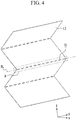
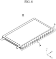
FIG. 4 to FIG. 8 are views illustrating various types of patterns included in the bending end region. -
FIG. 9 is a perspective view of a flexible rechargeable battery according to an exemplary embodiment of the present disclosure. -
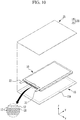
FIG. 10 is an exploded perspective view of a flexible rechargeable battery according toFIG. 9 . - Hereinafter, the present invention will be described more fully hereinafter with reference to the accompanying drawings, in which exemplary embodiments of the invention are shown. The present invention may be implemented in various ways, and is not limited to the exemplary embodiments described herein.
- Parts that are unrelated to the description of the exemplary embodiments are not shown to make the description clear, and like reference numerals designate like element throughout the specification.
- The size and thickness of the configurations are optionally shown in the drawings for convenience of description, and the present invention is not limited to as shown in the drawings.
- In addition, unless explicitly described to the contrary, the word "comprise" and variations such as "comprises" or "comprising" will be understood to imply the inclusion of stated elements but not the exclusion of any other elements.
-
FIG. 1 is an exploded perspective view of a stacked electrode assembly according to an exemplary embodiment of the present disclosure,FIG. 2 is a horizontal cross-sectional view of a stacked electrode assembly according toFIG. 1 , andFIG. 3 is a vertical cross-sectional view of a stacked electrode assembly according toFIG. 1 . - Referring to
FIG. 1 to FIG. 3 , a stackedelectrode assembly 10 according to an exemplary embodiment of the present disclosure includes afirst electrode 11, asecond electrode 12, and aseparator 13 disposed between thefirst electrode 11 and thesecond electrode 12. - In the present disclosure, the
separator 13 is characterized by having a continuous sheet shape. - Further, the
separator 13 may be bent in a first direction to surround thefirst electrode 11, and may be bent in a second direction which is opposite to the first direction to surround thesecond electrode 12. - Referring to
FIG. 1 , theseparator 13 of the continuous sheet shape is alternately bent in the first direction and the second direction opposite thereto. Thus, in the stackedelectrode assembly 10, the vertical cross-section of theseparator 13 may have a zigzag shape. - The
first electrode 11 is disposed inside theseparator 13 bent in the first direction and thesecond electrode 12 is disposed inside theseparator 13 bent in the second direction. When thefirst electrode 11 and thesecond electrode 12 are included in a plural number, thefirst electrode 11 and thesecond electrode 12 are alternately stacked. - Referring to
FIG. 2 , theseparator 13 of the present disclosure is bent to have a larger size than thefirst electrode 11 or thesecond electrode 12 when viewed from the horizontal cross-section (an xy direction) of theelectrode assembly 10. - In detail, the short side width SW1 of the
separator 13 is larger than the short side width NW1 of thesecond electrode 12, and the long side width SW2 of theseparator 13 is larger than the long side width NW2 of thesecond electrode 12. -
FIG. 2 shows only the short side and long side widths NW1 and NW2 of thesecond electrode 12 for convenience, but the short side and long side widths of thefirst electrode 11 may be formed to be the same as the short side and long side widths NW1 and NW2 of thesecond electrode 12. - Referring to
FIG. 2 andFIG. 3 , theelectrode assembly 10 has a shape including a pair of short sides and a pair of long sides. - Since the
separator 13 of the present disclosure is formed to be bent and has a larger size than thefirst electrode 11 and thesecond electrode 12, theseparator 13 does not overlap thefirst electrode 11 and thesecond electrode 12 on the side of the long side of theelectrode assembly 10 and has a region where theseparators 13 are overlapped with each other. - In the present disclosure, a region in which the
separators 13 folded in the end region where theseparator 13 is bent are overlapped with each other is referred to as a bending end region A. - The short width WA of the bending end region A may be 5 % to 10 % of the short side width NW1 of the
first electrode 11 or the short side width NW1 of thesecond electrode 12, and in detail, 7 % to 8 %. When the short width WA of the bending end region A satisfies the above range based on the short side width NW1 of thefirst electrode 11 or the short side width NW1 of thesecond electrode 12, in theelectrode assembly 10, a battery preventing a short between the positive electrode and the negative electrode and simultaneously having high energy density may be realized. - The present disclosure is characterized by including a plurality of patterns in the bending end region A.
-
FIG. 4 to FIG. 8 are views illustrating various types of patterns included in the bending end region. - First, referring to
FIG. 4 andFIG. 5 , theseparator 13 may be bent along a bending line BL, and the bending end region A may include a plurality of patterns arranged along the bending line BL. - The plurality of patterns may be a
linear pattern 51 arranged at a predetermined interval along the bending line BL. Thelinear pattern 51 may be formed to penetrate theseparator 13. - In addition, the process of forming the
linear pattern 51 may be performed before alternately stacking thefirst electrode 11 and thesecond electrode 12 on theseparator 13 bent with the zigzag shape or after alternately stacking thefirst electrode 11 and thesecond electrode 12. - That is, the
linear pattern 51 may be firstly formed in the bending end region A of theseparator 13 and then thefirst electrode 11 and thesecond electrode 12 may be alternately formed, and thefirst electrode 11 and thesecond electrode 12 may be alternately stacked inside theseparator 13 bent with the zigzag shape to form theelectrode assembly 10 and then thelinear pattern 51 may be formed. - However, when the
linear pattern 51 is firstly formed and then thefirst electrode 11 and thesecond electrode 12 are stacked, there is a merit that thelinear pattern 51 may be easily formed in the bending end region A of theseparator 13. - The
linear pattern 51 may be formed by, for example, a method of punching it by using jig along a previously cut bending line L, or using laser cutting. - Referring to
FIG. 6 , a plurality of patterns disposed in the bending end region A may be a plurality of circular patterns 52. - Although not shown, a plurality of patterns may be at least one of elliptical, triangle, quadrangle, and polygon shapes in addition to the circular pattern 52, or a shape in which a plurality of such shapes are mixed may be included in plural. At this time, the plurality of patterns may be formed to pass through the
separator 13. - The plurality of circular patterns 52 may be formed by appropriately adjusting the spacing in a range that does not affect the performance of the
electrode assembly 10 even if theseparator 13 is damaged so that the flexible characteristic may be realized. - The process of forming a plurality of patterns may be performed before alternately stacking the
first electrode 11 and thesecond electrode 12 on theseparator 13 bent with the zigzag shape or after alternately stacking thefirst electrode 11 and thesecond electrode 12. - That is, a plurality of patterns may be first formed in the bending end region A of the
separator 13 and then thefirst electrode 11 and thesecond electrode 12 may be alternately stacked, or thefirst electrode 11 and thesecond electrode 12 may be alternately stacked in theseparator 13 bent with the zigzag shape to form theelectrode assembly 10 and then a plurality of patterns may be formed. - However, when a plurality of patterns are first formed and the
first electrode 11 and thesecond electrode 12 are stacked, there is a process advantage that a pattern of various shapes may be easily formed in the bending end region A of theseparator 13. - At this time, a plurality of patterns may be formed by, for example, a method of punching or a method of laser cutting.
- Referring to
FIG. 7 , a plurality of patterns may be a protrusions anddepressions pattern 53. - The protrusions and
depressions pattern 53 may be formed to include a plurality ofrecess portions 53a recessed in the z-axis direction and a plurality ofconvex portions 53b protruded in the z-axis direction, as viewed from the vertical cross-section of theelectrode assembly 10. - The process of forming the protrusions and
depressions pattern 53 may be performed before alternately stacking thefirst electrode 11 and thesecond electrode 12 on theseparator 13 bent with the zigzag shape, or after alternately stacking thefirst electrode 11 and thesecond electrode 12. - In other words, the protrusions and
depressions pattern 53 may be first formed in the bending end region A of theseparator 13 and then thefirst electrode 11 and thesecond electrode 12 may be alternately stacked, or thefirst electrode 11 and thesecond electrode 12 may be stacked inside theseparator 13 bent with the zigzag shape to form theelectrode assembly 10 and then the protrusions anddepressions pattern 53 may be formed. - However, if the protrusions and
depressions pattern 53 are first formed on thebent separator 13 and thefirst electrode 11 and thesecond electrode 12 are stacked, there is a process advantage that the protrusions anddepressions pattern 53 may be easily formed in the bending end region A of theseparator 13. - The protrusions and
depressions pattern 53 may be formed, for example, by rolling it at room temperature or at a high temperature of 70 °C or less using jigs with protrusions and depressions. - Referring to
FIG. 8 , a plurality of patterns may include a plurality offracture portions 54. - The plurality of
fracture portions 54 may be disposed along the bending line BL of the bending end region A. - Also, a plurality of
fracture portions 54 means to be formed in the xy plane when viewed from the horizontal cross-section of theelectrode assembly 10. That is, a plurality offracture portions 54 may be formed of a shape in which a part of theseparator 13 is removed along the bending line BL disposed at the long side end of theelectrode assembly 10. - In
FIG. 8 , the plurality offracture portions 54 are formed to be triangular, but the plurality offracture portions 54 may have at least one shape of a quadrangle, a semicircle, and a semi-ellipse in addition to the triangle, or may be formed of mixed shapes thereof. - Also, the process of forming the plurality of
fracture portions 54 may be performed before alternately stacking thefirst electrode 11 and thesecond electrode 12 in theseparator 13 bent with the zigzag shape, or after alternately stacking thefirst electrode 11 and thesecond electrode 12. - In other words, a plurality of
fracture portions 54 may be first formed in the bending end region A of theseparator 13 and then thefirst electrode 11 and thesecond electrode 12 may be alternately stacked, or thefirst electrode 11 andsecond electrode 12 may be stacked in theseparator 13 bent with the zigzag shape to form theelectrode assembly 10 and then then plurality offracture portions 54 may be formed. - However, when the plurality of
fracture portions 54 are first formed and thefirst electrode 11 and thesecond electrode 12 are stacked, there is a process advantage that the plurality offracture portions 54 may be easily formed in the bending end region A of theseparator 13. - Further, the plurality of
fracture portions 54 may be formed by, for example, a method of punching by using a jig or a method of laser cutting. - Further, the thickness of the
separator 13 in the present disclosure may be, for example, 10 µm to 20 µm. More specifically, the thickness of theseparator 13 may be 12 µm to 18 µm, or 14 µm to 16 µm. When the thickness of theseparator 13 satisfies the above numerical range, the bending process of theseparator 13 may be performed smoothly, and theelectrode assembly 10 may be thinned according to the present disclosure in which the bending characteristic is improved. - Further, in the present disclosure, the
first electrode 11 may be a positive electrode and thesecond electrode 12 may be a negative electrode, but in some cases, thefirst electrode 11 may be the negative electrode and thesecond electrode 12 may be the positive electrode. Hereinafter, for convenience, an example in which thefirst electrode 11 is the positive electrode and thesecond electrode 12 is the negative electrode is described. - The
first electrode 11 includes a coated region 11a coated with a positive active material on the current collector of a thin metal plate, and an uncoated region 11b configured with the exposed current collector that is not coated with the positive active material. For example, the current collector and afirst electrode tab 21 of thefirst electrode 11 may be formed of aluminum (Al). - The
second electrode 12 includes a coated region 12a coated with a negative active material and an active material of thefirst electrode 11 on the current collector of a thin metal plate, and an uncoated region 12b configured with the exposed current collector on which the negative active material is not coated. For example, the current collector of thesecond electrode 12 and asecond electrode tab 22 may be formed of copper (Cu). - In the present disclosure, the coated regions 11a and 12a may be formed on both surfaces of the
first electrode 11 and thesecond electrode 12. However, in the case of thefirst electrode 11 and/or thesecond electrode 12 disposed outermost of theelectrode assembly 10, it is preferable that the coated regions 11a and 12a are not formed at the portion contacting the case when considering the energy density and the thinning of theelectrode assembly 10. - In the stacked state, the
first electrode 11 and thesecond electrode 12 are alternately arranged in both sides of the width direction (a y-axis direction) of the uncoated regions 11b and 12b. That is, inFIG. 2 , the uncoated region 11b of thefirst electrode 11 is disposed to the right and the uncoated region 12b of thesecond electrode 12 is disposed to the left. - Also, the
first electrode tab 21 is connected to the uncoated region 11b of thefirst electrode 11 and thesecond electrode tab 22 is connected to the uncoated region 12b of thesecond electrode 12. Therefore, the first andsecond electrode tabs second electrode tabs second electrode tabs - Since the
electrode assembly 10 according to the present disclosure includes a plurality ofpatterns separator 13, when bending theelectrode assembly 10, a tensile stress and a compression stress applied to the outside and inside of theelectrode assembly 10 may be uniformly dispersed, thereby realizing an excellent flexibility characteristic. - Next, the configuration of the flexible rechargeable battery according to an exemplary embodiment of the present disclosure will be described.
-
FIG. 9 is a perspective view of a flexible rechargeable battery according to an exemplary embodiment of the present disclosure, andFIG. 10 is an exploded perspective view of a flexible rechargeable battery according toFIG. 9 . - Referring to
FIG. 9 andFIG. 10 , another flexiblerechargeable battery 200 according to an exemplary embodiment of the present disclosure includes the above-describedstacked electrode assembly 10 and a case 130 receiving them. - In this instance, the case 130 may include an upper case 131 and a lower case 132. The upper case 131 and the lower case 132 accommodate the stacked
electrode assembly 10 and form the flexible rechargeable battery by joining the edges thereof together by heat fusion or the like. - The
first electrode tab 21 andsecond electrode tab 22 may be drawn out of the case 130 and electrically connected to a set of protective circuit modules (not shown) and electronic devices. Here, the first andsecond electrode tabs - Meanwhile, each of the upper case 131 and the lower case 132 may have a structure in which an outer resin layer 130a, a metal layer 130b, and an inner resin layer 130c are sequentially stacked, as an example.
- First, the outer resin layer 130a serves as a base substrate and a protective layer. The outer resin layer 130a, for example, may be formed of one or more selected from a group including polyethylene terephthalate, polybutylene terephthalate, polyethylene naphthalate, polybutylene naphthalate, a polyester copolymer, a polycarbonate, and a nylon film, but is not limited thereto.
- Next, the metal layer 130b may prevent moisture and the like from penetrating the flexible
rechargeable battery 200 according to the present disclosure. - The metal layer 130b may be made of, for example, at least one material selected from a group including alloys of Fe, C, Cr, and Mn, alloys of Fe, C, Cr, and Ni, Cu, Al, or their equivalents, but is not limited thereto.
- Also, the metal layer 130b is preferably formed as thick as possible in a range that does not impair the flexibility of the flexible
rechargeable battery 200, from the viewpoint of the effect of preventing moisture permeation. - Next, the inner resin layer 130c also serves to bond the
separator 13 or the cross-section of thefirst electrode 11 or thesecond electrode 12, which is not coated with the active material. In some cases, the inner resin layer 130c may serve to directly bond the edges of the upper case 131 and the lower case 132 without additional adhesives. - The inner resin layer 130c, for example, may be formed of a polyolefin or a copolymer of a polyolefin, and more specifically, the polyolefin may be polyethylene (PE) or polypropylene (PP), but is not limited thereto.
- While this invention has been described in connection with what is presently considered to be practical exemplary embodiments, it is to be understood that the invention is not limited to the disclosed embodiments. On the contrary, it is intended to cover various modifications and equivalent arrangements included within the spirit and scope of the appended claims.
-
- 200:
- rechargeable battery
- 10:
- electrode assembly
- 21:
- positive electrode tab
- 22:
- negative electrode tab
- 130:
- case
- 131:
- upper case
- 132:
- lower case
- 11:
- positive electrode
- 11a:
- positive coated region
- 11b:
- positive uncoated region
- 12:
- negative electrode
- 12a:
- negative coated region
- 12b:
- negative uncoated region
- 13:
- separator
Claims (10)
- A stacked electrode assembly comprising:a first electrode;a second electrode stacked on one surface or both surfaces of the first electrode; anda separator disposed between the first electrode and the second electrode,wherein the separator has a continuous sheet shape, is bent in a first direction to surround the first electrode and in a second direction as an opposite direction to the first direction to surround the second electrode, anda bending end region of the separator includes a plurality of patterns.
- The stacked electrode assembly of claim 1, wherein
the plurality of patterns are arranged along a bending line of the bending end region. - The stacked electrode assembly of claim 2, wherein
the plurality of patterns are linear patterns. - The stacked electrode assembly of claim 1, wherein
the plurality of patterns have at least one shape of circular, elliptical, triangular, quadrangular, polygonal, and mixed forms thereof. - The stacked electrode assembly of claim 1, wherein
the plurality of patterns include a protrusions and depressions pattern including a plurality of recess portions and a plurality of convex portions when viewed from a vertical cross-section of the stacked electrode assembly. - The stacked electrode assembly of claim 1, wherein
the plurality of patterns include a plurality of fracture portions disposed along a bending line of a bending end region when viewed from a horizontal cross-section of the stacked electrode assembly. - The stacked electrode assembly of claim 6, wherein
the plurality of fracture portions have a shape of at least one of a triangle, a quadrangle, a semicircle, a semi-ellipse, and mixed forms thereof. - The stacked electrode assembly of claim 1, wherein
the bending end region does not overlap the first electrode and the second electrode. - The stacked electrode assembly of claim 1, wherein
a thickness of the separator is 10 µm to 20 µm. - A flexible rechargeable battery comprising:the stacked electrode assembly of any one of claim 1 to claim 9; anda case receiving the stacked electrode assembly.
Applications Claiming Priority (2)
| Application Number | Priority Date | Filing Date | Title |
|---|---|---|---|
| KR1020160114632A KR102278444B1 (en) | 2016-09-06 | 2016-09-06 | Stacked electrode assembly and flexible rechargeable battery comprising the same |
| PCT/KR2017/009671 WO2018048165A1 (en) | 2016-09-06 | 2017-09-05 | Stacked electrode assembly and flexible secondary battery comprising same |
Publications (3)
| Publication Number | Publication Date |
|---|---|
| EP3512020A1 true EP3512020A1 (en) | 2019-07-17 |
| EP3512020A4 EP3512020A4 (en) | 2020-05-06 |
| EP3512020B1 EP3512020B1 (en) | 2025-11-05 |
Family
ID=61562461
Family Applications (1)
| Application Number | Title | Priority Date | Filing Date |
|---|---|---|---|
| EP17849049.6A Active EP3512020B1 (en) | 2016-09-06 | 2017-09-05 | Stacked electrode assembly and flexible rechargeable battery comprising the same |
Country Status (6)
| Country | Link |
|---|---|
| US (1) | US11437651B2 (en) |
| EP (1) | EP3512020B1 (en) |
| JP (1) | JP6748297B2 (en) |
| KR (1) | KR102278444B1 (en) |
| CN (1) | CN109690857B (en) |
| WO (1) | WO2018048165A1 (en) |
Cited By (1)
| Publication number | Priority date | Publication date | Assignee | Title |
|---|---|---|---|---|
| EP4336611A1 (en) * | 2022-08-17 | 2024-03-13 | SK On Co., Ltd. | Electrode assembly for secondary battery, manufacturing method thereof, and lithium secondary battery comprising same |
Families Citing this family (12)
| Publication number | Priority date | Publication date | Assignee | Title |
|---|---|---|---|---|
| KR102311950B1 (en) * | 2018-11-19 | 2021-10-14 | 주식회사 엘지에너지솔루션 | Electrode-assembly |
| JP7253399B2 (en) * | 2019-02-05 | 2023-04-06 | 本田技研工業株式会社 | secondary battery |
| KR102874645B1 (en) * | 2019-06-17 | 2025-10-23 | 삼성에스디아이 주식회사 | Electrode assembly and secondary battery having the same |
| KR102773534B1 (en) * | 2020-04-20 | 2025-02-27 | 주식회사 엘지에너지솔루션 | The Electrode Assembly And The Secondary Battery |
| KR102774308B1 (en) | 2020-05-11 | 2025-03-04 | 주식회사 엘지에너지솔루션 | Secondary battery and and manufacturing method for secondary battery |
| KR20220087167A (en) | 2020-12-17 | 2022-06-24 | 삼성에스디아이 주식회사 | Electrode assembly and secondary battery having the same |
| CN214477590U (en) * | 2021-02-09 | 2021-10-22 | 无锡先导智能装备股份有限公司 | Composite device and lamination machine |
| CN116745953A (en) * | 2021-11-23 | 2023-09-12 | 宁德时代新能源科技股份有限公司 | Electrode sheet, electrode assembly, battery cell, battery, electrical device and manufacturing method |
| KR20230147892A (en) * | 2022-04-15 | 2023-10-24 | 주식회사 엘지에너지솔루션 | Electrode assembly and battery cell including same |
| KR102742757B1 (en) * | 2022-12-07 | 2024-12-12 | 주식회사 엘지에너지솔루션 | An electrode assembly and a method of manufacturing the same |
| JP7823630B2 (en) * | 2023-05-25 | 2026-03-04 | トヨタ自動車株式会社 | Energy storage cell |
| JP7816316B2 (en) * | 2023-08-29 | 2026-02-18 | トヨタ自動車株式会社 | Energy storage cell |
Family Cites Families (29)
| Publication number | Priority date | Publication date | Assignee | Title |
|---|---|---|---|---|
| KR100313119B1 (en) * | 1999-01-26 | 2001-11-03 | 김순택 | Electrode assembly used in secondary battery |
| US6740446B2 (en) | 2001-02-28 | 2004-05-25 | Ovonic Battery Company, Inc. | Electrochemical cell with zigzag electrodes |
| WO2004097971A1 (en) | 2003-04-25 | 2004-11-11 | Enerland Co. Ltd. | Stacked lithium secondary battery and its fabrication |
| KR100514214B1 (en) | 2003-04-25 | 2005-09-13 | 주식회사 에너랜드 | Stacked type lithium secondary battery with separated two films of separator and its fabrication |
| JP5269296B2 (en) | 2006-05-12 | 2013-08-21 | 株式会社東芝 | Secondary battery |
| KR100907623B1 (en) | 2006-05-15 | 2009-07-15 | 주식회사 엘지화학 | Novel laminated electrode assembly for secondary battery |
| KR20100084326A (en) | 2009-01-16 | 2010-07-26 | 도레이첨단소재 주식회사 | Separator film for lithium secondary battery and lithium secondary battery with the same |
| KR101084075B1 (en) | 2009-11-03 | 2011-11-16 | 삼성에스디아이 주식회사 | Secondary Battery and Manufacturing Method Thereof |
| CN103081200B (en) * | 2010-08-11 | 2015-08-19 | 日本自动精机株式会社 | Lamination method and device for positive and negative plates |
| KR101199125B1 (en) * | 2010-09-02 | 2012-11-09 | 삼성에스디아이 주식회사 | Electrode assembly including bending portions and secondary battery having the same |
| JP5699559B2 (en) | 2010-11-17 | 2015-04-15 | ソニー株式会社 | Non-aqueous electrolyte battery |
| JP5830953B2 (en) * | 2010-11-17 | 2015-12-09 | ソニー株式会社 | Secondary battery, battery unit and battery module |
| KR101543055B1 (en) | 2011-01-14 | 2015-08-07 | 주식회사 엘지화학 | Stack and Folding-Typed Electrode Assembly Having Improved Safety Property and Method for preparation of the same |
| US20120189894A1 (en) * | 2011-01-26 | 2012-07-26 | Samsung Sdi Co., Ltd. | Electrode assembly and secondary battery including the same |
| KR20130008883A (en) | 2011-07-13 | 2013-01-23 | 주식회사 엘지화학 | Electrode assembly of excellent productability and secondary battery comprising the same |
| US8929085B2 (en) | 2011-09-30 | 2015-01-06 | Apple Inc. | Flexible electronic devices |
| KR101310734B1 (en) * | 2011-12-27 | 2013-09-24 | 주식회사 엘지화학 | Electrode assembly and secondary battery using the same |
| KR101332282B1 (en) | 2012-03-14 | 2013-11-22 | 주식회사 엘지화학 | Electrode Assembly of Novel Structure and Battery Cell Comprising the Same |
| KR101901370B1 (en) * | 2012-04-02 | 2018-09-21 | 에스케이이노베이션 주식회사 | Battery Cell |
| JP2013254629A (en) * | 2012-06-06 | 2013-12-19 | Toyota Industries Corp | Power storage device and secondary battery |
| KR101651712B1 (en) * | 2012-07-26 | 2016-08-26 | 에스케이이노베이션 주식회사 | Secondary Battery |
| US9246185B2 (en) | 2013-03-14 | 2016-01-26 | Sion Power Corporation | Electrochemical cell having a folded electrode and separator, battery including the same, and method of forming same |
| CN103490089A (en) * | 2013-06-17 | 2014-01-01 | 中国科学院物理研究所 | Electrode subassembly, preparation method thereof and lithium secondary battery |
| KR101634772B1 (en) | 2013-10-07 | 2016-06-29 | 주식회사 엘지화학 | Battery Cell Comprising Zigzag Type Electrode Assembly |
| CN203800123U (en) * | 2014-04-01 | 2014-08-27 | 广州中国科学院工业技术研究院 | Electrode assembly and lithium secondary battery |
| KR101675950B1 (en) | 2014-05-08 | 2016-11-14 | 주식회사 엘지화학 | Electrode Assembly Having Alternatively-arranged Noncoating Parts and Coating Parts and Flexible Battery Cell Comprising the Same |
| JP6048477B2 (en) | 2014-11-17 | 2016-12-21 | ソニー株式会社 | Method for producing non-aqueous electrolyte battery |
| KR102314732B1 (en) * | 2015-01-21 | 2021-10-19 | 주식회사 아모그린텍 | Flexible battery and wearable device containing the same |
| CN105655629B (en) * | 2016-03-31 | 2019-02-26 | 中航锂电(洛阳)有限公司 | A kind of coiled battery pole piece, takeup type battery core, battery |
-
2016
- 2016-09-06 KR KR1020160114632A patent/KR102278444B1/en active Active
-
2017
- 2017-09-05 WO PCT/KR2017/009671 patent/WO2018048165A1/en not_active Ceased
- 2017-09-05 JP JP2019512604A patent/JP6748297B2/en active Active
- 2017-09-05 CN CN201780054344.2A patent/CN109690857B/en active Active
- 2017-09-05 US US16/330,223 patent/US11437651B2/en active Active
- 2017-09-05 EP EP17849049.6A patent/EP3512020B1/en active Active
Cited By (1)
| Publication number | Priority date | Publication date | Assignee | Title |
|---|---|---|---|---|
| EP4336611A1 (en) * | 2022-08-17 | 2024-03-13 | SK On Co., Ltd. | Electrode assembly for secondary battery, manufacturing method thereof, and lithium secondary battery comprising same |
Also Published As
| Publication number | Publication date |
|---|---|
| US20190252726A1 (en) | 2019-08-15 |
| JP6748297B2 (en) | 2020-08-26 |
| KR20180027262A (en) | 2018-03-14 |
| KR102278444B1 (en) | 2021-07-16 |
| US11437651B2 (en) | 2022-09-06 |
| JP2019526903A (en) | 2019-09-19 |
| EP3512020A4 (en) | 2020-05-06 |
| CN109690857A (en) | 2019-04-26 |
| EP3512020B1 (en) | 2025-11-05 |
| WO2018048165A1 (en) | 2018-03-15 |
| CN109690857B (en) | 2022-02-15 |
Similar Documents
| Publication | Publication Date | Title |
|---|---|---|
| EP3512020B1 (en) | Stacked electrode assembly and flexible rechargeable battery comprising the same | |
| CN105609693B (en) | Electrode assembly and battery pack having the same | |
| US9685679B2 (en) | Stepwise electrode assembly having variously-shaped corner and secondary battery, battery pack and device comprising the same | |
| US10741820B2 (en) | Rechargeable battery | |
| US9312528B2 (en) | Rechargeable battery and battery module | |
| US20110129701A1 (en) | Secondary battery | |
| KR20180010073A (en) | Flexible rechargeable battery | |
| CN102044701A (en) | Battery pack and method of manufacturing the same | |
| US9246153B2 (en) | Secondary battery | |
| WO2018168982A1 (en) | Battery system and busbar used in same battery system | |
| CN106486634B (en) | Battery module | |
| US20160079574A1 (en) | Electrode assembly and secondary battery including the same | |
| US20120219834A1 (en) | Secondary battery | |
| EP4421942A2 (en) | Battery pack | |
| CN108140872B (en) | Electrode assembly including electrode plate having bonded additional tab formed thereon | |
| US20170110763A1 (en) | Rechargeable battery | |
| CN111834658A (en) | Secondary battery | |
| EP4525127B1 (en) | Electrode assembly and battery | |
| KR20240073603A (en) | Secondary battery and method for preparing the same | |
| KR20190051855A (en) | Cross-folded flexible lithium secondary battery | |
| EP4679585A1 (en) | Secondary battery and secondary battery module | |
| JP7794836B2 (en) | Energy storage element | |
| US20230411806A1 (en) | Secondary battery | |
| KR20250138084A (en) | Electrode for secondary battery, electrode assembly for secondary battery comprising the same, and secondary battery comprising the same | |
| WO2024057711A1 (en) | Secondary battery |
Legal Events
| Date | Code | Title | Description |
|---|---|---|---|
| STAA | Information on the status of an ep patent application or granted ep patent |
Free format text: STATUS: THE INTERNATIONAL PUBLICATION HAS BEEN MADE |
|
| PUAI | Public reference made under article 153(3) epc to a published international application that has entered the european phase |
Free format text: ORIGINAL CODE: 0009012 |
|
| STAA | Information on the status of an ep patent application or granted ep patent |
Free format text: STATUS: REQUEST FOR EXAMINATION WAS MADE |
|
| 17P | Request for examination filed |
Effective date: 20190405 |
|
| AK | Designated contracting states |
Kind code of ref document: A1 Designated state(s): AL AT BE BG CH CY CZ DE DK EE ES FI FR GB GR HR HU IE IS IT LI LT LU LV MC MK MT NL NO PL PT RO RS SE SI SK SM TR |
|
| AX | Request for extension of the european patent |
Extension state: BA ME |
|
| DAV | Request for validation of the european patent (deleted) | ||
| DAX | Request for extension of the european patent (deleted) | ||
| A4 | Supplementary search report drawn up and despatched |
Effective date: 20200403 |
|
| RIC1 | Information provided on ipc code assigned before grant |
Ipc: H01M 10/04 20060101AFI20200330BHEP Ipc: H01M 2/10 20060101ALI20200330BHEP Ipc: H01M 10/0583 20100101ALI20200330BHEP Ipc: H01M 2/18 20060101ALI20200330BHEP |
|
| STAA | Information on the status of an ep patent application or granted ep patent |
Free format text: STATUS: EXAMINATION IS IN PROGRESS |
|
| 17Q | First examination report despatched |
Effective date: 20230707 |
|
| REG | Reference to a national code |
Ref legal event code: R079 Ref country code: DE Ref legal event code: R079 Ref document number: 602017092583 Country of ref document: DE Free format text: PREVIOUS MAIN CLASS: H01M0010040000 Ipc: H01M0010058300 |
|
| RIC1 | Information provided on ipc code assigned before grant |
Ipc: H01M 50/466 20210101ALI20250303BHEP Ipc: H01M 50/536 20210101ALI20250303BHEP Ipc: H01M 10/04 20060101ALI20250303BHEP Ipc: H01M 50/534 20210101ALI20250303BHEP Ipc: H01M 50/538 20210101ALI20250303BHEP Ipc: H01M 50/24 20210101ALI20250303BHEP Ipc: H01M 10/0583 20100101AFI20250303BHEP |
|
| GRAP | Despatch of communication of intention to grant a patent |
Free format text: ORIGINAL CODE: EPIDOSNIGR1 |
|
| STAA | Information on the status of an ep patent application or granted ep patent |
Free format text: STATUS: GRANT OF PATENT IS INTENDED |
|
| INTG | Intention to grant announced |
Effective date: 20250417 |
|
| GRAS | Grant fee paid |
Free format text: ORIGINAL CODE: EPIDOSNIGR3 |
|
| GRAA | (expected) grant |
Free format text: ORIGINAL CODE: 0009210 |
|
| STAA | Information on the status of an ep patent application or granted ep patent |
Free format text: STATUS: THE PATENT HAS BEEN GRANTED |
|
| AK | Designated contracting states |
Kind code of ref document: B1 Designated state(s): AL AT BE BG CH CY CZ DE DK EE ES FI FR GB GR HR HU IE IS IT LI LT LU LV MC MK MT NL NO PL PT RO RS SE SI SK SM TR |
|
| REG | Reference to a national code |
Ref country code: CH Ref legal event code: F10 Free format text: ST27 STATUS EVENT CODE: U-0-0-F10-F00 (AS PROVIDED BY THE NATIONAL OFFICE) Effective date: 20251105 Ref country code: GB Ref legal event code: FG4D |
|
| REG | Reference to a national code |
Ref country code: DE Ref legal event code: R096 Ref document number: 602017092583 Country of ref document: DE |
|
| REG | Reference to a national code |
Ref country code: IE Ref legal event code: FG4D |
|
| REG | Reference to a national code |
Ref country code: NL Ref legal event code: MP Effective date: 20251105 |
|
| PG25 | Lapsed in a contracting state [announced via postgrant information from national office to epo] |
Ref country code: ES Free format text: LAPSE BECAUSE OF FAILURE TO SUBMIT A TRANSLATION OF THE DESCRIPTION OR TO PAY THE FEE WITHIN THE PRESCRIBED TIME-LIMIT Effective date: 20251105 |
|
| REG | Reference to a national code |
Ref country code: LT Ref legal event code: MG9D |
|
| PG25 | Lapsed in a contracting state [announced via postgrant information from national office to epo] |
Ref country code: NO Free format text: LAPSE BECAUSE OF FAILURE TO SUBMIT A TRANSLATION OF THE DESCRIPTION OR TO PAY THE FEE WITHIN THE PRESCRIBED TIME-LIMIT Effective date: 20260205 |
|
| PG25 | Lapsed in a contracting state [announced via postgrant information from national office to epo] |
Ref country code: HR Free format text: LAPSE BECAUSE OF FAILURE TO SUBMIT A TRANSLATION OF THE DESCRIPTION OR TO PAY THE FEE WITHIN THE PRESCRIBED TIME-LIMIT Effective date: 20251105 Ref country code: FI Free format text: LAPSE BECAUSE OF FAILURE TO SUBMIT A TRANSLATION OF THE DESCRIPTION OR TO PAY THE FEE WITHIN THE PRESCRIBED TIME-LIMIT Effective date: 20251105 Ref country code: AT Free format text: LAPSE BECAUSE OF FAILURE TO SUBMIT A TRANSLATION OF THE DESCRIPTION OR TO PAY THE FEE WITHIN THE PRESCRIBED TIME-LIMIT Effective date: 20251105 |
|
| REG | Reference to a national code |
Ref country code: AT Ref legal event code: MK05 Ref document number: 1855396 Country of ref document: AT Kind code of ref document: T Effective date: 20251105 |
|
| PG25 | Lapsed in a contracting state [announced via postgrant information from national office to epo] |
Ref country code: NL Free format text: LAPSE BECAUSE OF FAILURE TO SUBMIT A TRANSLATION OF THE DESCRIPTION OR TO PAY THE FEE WITHIN THE PRESCRIBED TIME-LIMIT Effective date: 20251105 |
|
| PG25 | Lapsed in a contracting state [announced via postgrant information from national office to epo] |
Ref country code: RS Free format text: LAPSE BECAUSE OF FAILURE TO SUBMIT A TRANSLATION OF THE DESCRIPTION OR TO PAY THE FEE WITHIN THE PRESCRIBED TIME-LIMIT Effective date: 20260205 |
|
| PG25 | Lapsed in a contracting state [announced via postgrant information from national office to epo] |
Ref country code: IS Free format text: LAPSE BECAUSE OF FAILURE TO SUBMIT A TRANSLATION OF THE DESCRIPTION OR TO PAY THE FEE WITHIN THE PRESCRIBED TIME-LIMIT Effective date: 20260305 |
|
| PG25 | Lapsed in a contracting state [announced via postgrant information from national office to epo] |
Ref country code: PT Free format text: LAPSE BECAUSE OF FAILURE TO SUBMIT A TRANSLATION OF THE DESCRIPTION OR TO PAY THE FEE WITHIN THE PRESCRIBED TIME-LIMIT Effective date: 20260305 |
|
| PG25 | Lapsed in a contracting state [announced via postgrant information from national office to epo] |
Ref country code: PL Free format text: LAPSE BECAUSE OF FAILURE TO SUBMIT A TRANSLATION OF THE DESCRIPTION OR TO PAY THE FEE WITHIN THE PRESCRIBED TIME-LIMIT Effective date: 20251105 |
|
| PG25 | Lapsed in a contracting state [announced via postgrant information from national office to epo] |
Ref country code: LV Free format text: LAPSE BECAUSE OF FAILURE TO SUBMIT A TRANSLATION OF THE DESCRIPTION OR TO PAY THE FEE WITHIN THE PRESCRIBED TIME-LIMIT Effective date: 20251105 |