EP3512003A1 - Component for collecting current and battery - Google Patents
Component for collecting current and battery Download PDFInfo
- Publication number
- EP3512003A1 EP3512003A1 EP19151542.8A EP19151542A EP3512003A1 EP 3512003 A1 EP3512003 A1 EP 3512003A1 EP 19151542 A EP19151542 A EP 19151542A EP 3512003 A1 EP3512003 A1 EP 3512003A1
- Authority
- EP
- European Patent Office
- Prior art keywords
- electrode assembly
- connecting structure
- component
- holding arrangement
- inner connecting
- Prior art date
- Legal status (The legal status is an assumption and is not a legal conclusion. Google has not performed a legal analysis and makes no representation as to the accuracy of the status listed.)
- Granted
Links
- 239000002184 metal Substances 0.000 claims description 4
- 230000000712 assembly Effects 0.000 abstract description 8
- 238000000429 assembly Methods 0.000 abstract description 8
- 238000005452 bending Methods 0.000 description 15
- 238000000034 method Methods 0.000 description 4
- HBBGRARXTFLTSG-UHFFFAOYSA-N Lithium ion Chemical compound [Li+] HBBGRARXTFLTSG-UHFFFAOYSA-N 0.000 description 3
- 229910001416 lithium ion Inorganic materials 0.000 description 3
- 238000004519 manufacturing process Methods 0.000 description 3
- 239000000243 solution Substances 0.000 description 3
- 239000003792 electrolyte Substances 0.000 description 2
- 238000004146 energy storage Methods 0.000 description 2
- 238000005516 engineering process Methods 0.000 description 2
- 238000002347 injection Methods 0.000 description 2
- 239000007924 injection Substances 0.000 description 2
- 238000012986 modification Methods 0.000 description 2
- 230000004048 modification Effects 0.000 description 2
- 238000006467 substitution reaction Methods 0.000 description 2
- 238000003466 welding Methods 0.000 description 2
- 230000005611 electricity Effects 0.000 description 1
- 230000014509 gene expression Effects 0.000 description 1
- 238000003825 pressing Methods 0.000 description 1
- 238000003860 storage Methods 0.000 description 1
Images


Classifications
-
- H—ELECTRICITY
- H01—ELECTRIC ELEMENTS
- H01M—PROCESSES OR MEANS, e.g. BATTERIES, FOR THE DIRECT CONVERSION OF CHEMICAL ENERGY INTO ELECTRICAL ENERGY
- H01M10/00—Secondary cells; Manufacture thereof
- H01M10/04—Construction or manufacture in general
- H01M10/0436—Small-sized flat cells or batteries for portable equipment
-
- H—ELECTRICITY
- H01—ELECTRIC ELEMENTS
- H01M—PROCESSES OR MEANS, e.g. BATTERIES, FOR THE DIRECT CONVERSION OF CHEMICAL ENERGY INTO ELECTRICAL ENERGY
- H01M10/00—Secondary cells; Manufacture thereof
- H01M10/04—Construction or manufacture in general
- H01M10/049—Processes for forming or storing electrodes in the battery container
-
- H—ELECTRICITY
- H01—ELECTRIC ELEMENTS
- H01M—PROCESSES OR MEANS, e.g. BATTERIES, FOR THE DIRECT CONVERSION OF CHEMICAL ENERGY INTO ELECTRICAL ENERGY
- H01M10/00—Secondary cells; Manufacture thereof
- H01M10/05—Accumulators with non-aqueous electrolyte
- H01M10/058—Construction or manufacture
-
- H—ELECTRICITY
- H01—ELECTRIC ELEMENTS
- H01M—PROCESSES OR MEANS, e.g. BATTERIES, FOR THE DIRECT CONVERSION OF CHEMICAL ENERGY INTO ELECTRICAL ENERGY
- H01M50/00—Constructional details or processes of manufacture of the non-active parts of electrochemical cells other than fuel cells, e.g. hybrid cells
- H01M50/50—Current conducting connections for cells or batteries
-
- H—ELECTRICITY
- H01—ELECTRIC ELEMENTS
- H01M—PROCESSES OR MEANS, e.g. BATTERIES, FOR THE DIRECT CONVERSION OF CHEMICAL ENERGY INTO ELECTRICAL ENERGY
- H01M10/00—Secondary cells; Manufacture thereof
- H01M10/05—Accumulators with non-aqueous electrolyte
- H01M10/052—Li-accumulators
- H01M10/0525—Rocking-chair batteries, i.e. batteries with lithium insertion or intercalation in both electrodes; Lithium-ion batteries
-
- H—ELECTRICITY
- H01—ELECTRIC ELEMENTS
- H01M—PROCESSES OR MEANS, e.g. BATTERIES, FOR THE DIRECT CONVERSION OF CHEMICAL ENERGY INTO ELECTRICAL ENERGY
- H01M50/00—Constructional details or processes of manufacture of the non-active parts of electrochemical cells other than fuel cells, e.g. hybrid cells
- H01M50/50—Current conducting connections for cells or batteries
- H01M50/531—Electrode connections inside a battery casing
- H01M50/536—Electrode connections inside a battery casing characterised by the method of fixing the leads to the electrodes, e.g. by welding
-
- H—ELECTRICITY
- H01—ELECTRIC ELEMENTS
- H01M—PROCESSES OR MEANS, e.g. BATTERIES, FOR THE DIRECT CONVERSION OF CHEMICAL ENERGY INTO ELECTRICAL ENERGY
- H01M50/00—Constructional details or processes of manufacture of the non-active parts of electrochemical cells other than fuel cells, e.g. hybrid cells
- H01M50/50—Current conducting connections for cells or batteries
- H01M50/543—Terminals
- H01M50/547—Terminals characterised by the disposition of the terminals on the cells
- H01M50/55—Terminals characterised by the disposition of the terminals on the cells on the same side of the cell
-
- H—ELECTRICITY
- H01—ELECTRIC ELEMENTS
- H01M—PROCESSES OR MEANS, e.g. BATTERIES, FOR THE DIRECT CONVERSION OF CHEMICAL ENERGY INTO ELECTRICAL ENERGY
- H01M50/00—Constructional details or processes of manufacture of the non-active parts of electrochemical cells other than fuel cells, e.g. hybrid cells
- H01M50/50—Current conducting connections for cells or batteries
- H01M50/543—Terminals
- H01M50/552—Terminals characterised by their shape
- H01M50/553—Terminals adapted for prismatic, pouch or rectangular cells
-
- Y—GENERAL TAGGING OF NEW TECHNOLOGICAL DEVELOPMENTS; GENERAL TAGGING OF CROSS-SECTIONAL TECHNOLOGIES SPANNING OVER SEVERAL SECTIONS OF THE IPC; TECHNICAL SUBJECTS COVERED BY FORMER USPC CROSS-REFERENCE ART COLLECTIONS [XRACs] AND DIGESTS
- Y02—TECHNOLOGIES OR APPLICATIONS FOR MITIGATION OR ADAPTATION AGAINST CLIMATE CHANGE
- Y02E—REDUCTION OF GREENHOUSE GAS [GHG] EMISSIONS, RELATED TO ENERGY GENERATION, TRANSMISSION OR DISTRIBUTION
- Y02E60/00—Enabling technologies; Technologies with a potential or indirect contribution to GHG emissions mitigation
- Y02E60/10—Energy storage using batteries
Landscapes
- Chemical & Material Sciences (AREA)
- Chemical Kinetics & Catalysis (AREA)
- Electrochemistry (AREA)
- General Chemical & Material Sciences (AREA)
- Engineering & Computer Science (AREA)
- Manufacturing & Machinery (AREA)
- Materials Engineering (AREA)
- Connection Of Batteries Or Terminals (AREA)
Abstract
Description
- The present disclosure relates to the technical field of energy storage components, in particular to a component for collecting a current and a battery.
- Lithium-ion batteries are widely used in portable electronic devices such as mobile phones, digital video cameras and laptop computers due to their high energy density, high power density, repetitively recyclable use, and durable storage. Lithium-ion batteries also have an extensive prospect in their use in electric vehicles such as electric cars and electric motorcycles, as well as large-and-middle-sized electric equipment such as energy storage facilities.
- With improvement of electric vehicle technologies, electric vehicles are increasingly making their way into people's daily lives. While safety performance is demanded from lithium-ion batteries which provide energy to electric vehicles, higher energy density is more and more demanded from cells. In order to improve energy density of an electrode assembly, a component for collecting a current of a battery is bent after the component for collecting a current is welded to a tab of an electrode assembly, thereby reducing internal space occupied by the component for collecting a current, in the existing technologies.
- Some embodiments of the present disclosure provide a component for collecting a current and a battery to reduce damage to an electrode assembly when bending the component for collecting a current.
- Some embodiments of the present disclosure provide a component for collecting a current for electrically connecting an electrode assembly to the outside. The component for collecting a current comprises an introducing body and a connection body bendably arranged relative to the introducing body. The introducing body comprises a holding arrangement to be fixed when the connection body is bent.
- In some embodiments, the introducing body further includes an inner connecting structure connecting the holding arrangement and the connection body. The holding arrangement protrudes relative to the inner connecting structure.
- In some embodiments, the inner connecting structure is in the form of a sheet. A surface of the holding arrangement and a surface of the inner connecting structure are not on the same surface.
- In some embodiments, the holding arrangement includes a first holding part and a second holding part that are respectively arranged at both ends of the inner connecting structure.
- In some embodiments, the introducing body includes an outer connecting structure for electrically connecting to the outside. The first holding part is arranged between the outer connecting structure and the inner connecting structure, and the second holding part is arranged at an end of the inner connecting structure away from the outer connecting structure.
- In some embodiments, there are two connecting bodies respectively located on two lateral sides of the introducing body.
- In some embodiments, the component for collecting a current is formed integrally by a piece of metal that is in the form of a sheet.
- Some embodiments of the present disclosure provide a battery. The battery includes an electrode assembly and a component for collecting a current as aforementioned, a connection body connected to a tab of the electrode assembly, and the introducing body electronically connected to the outside.
- In some embodiments, the battery includes a cap plate arranged on top of the electrode assembly, the holding arrangement is arranged on a side of the electrode assembly, and a protruding distance of the holding arrangement relative to the side of the electrode assembly is shorter than a protruding distance of the cap plate edge relative to the side of the electrode assembly.
- In some embodiments, the introducing body extends along the side of the electrode assembly, and an accommodating space is formed between a surface of the holding arrangement adjacent to the electrode assembly and a surface of the electrode assembly.
- According to the component for collecting a current and the battery provided by some embodiments of the present disclosure, the component for collecting a current includes the introducing body and the connection body bendably arranged relative to the introducing body, and the introducing body includes the holding arrangement to be fixed when bending the connection body. When bending the connection body of some embodiments of the present disclosure, an operator may fix and clamp the holding arrangement arranged on a holding body by using a clamping tool, so that a stress applied on the component for collecting a current may be transferred to the clamping tool when bending the connection body, in order to reduce the stress from damaging the electrode assembly.
- Further features of some embodiments of the present disclosure and their advantages will become apparent from the following detailed description on exemplary embodiments of the present disclosure with reference to the drawings.
- As a part of the present disclosure, drawings illustrated here are used to provide further understanding of the present disclosure. The schematic embodiments and description of the present disclosure are used for describing the present disclosure but do not constitute an inappropriate limit to the present disclosure. In the drawings:
-
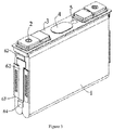
Figure 1 is a schematic perspective view of a battery when a component for collecting a current according to some embodiments of the present disclosure is in a first state; -
Figure 2 is a schematic front view of the battery shown inFigure 1 ; -
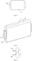
Figure 3 is a schematic perspective view of the battery when the component for collecting a current according to some embodiments of the present disclosure is in a second state; -
Figure 4 is a schematic perspective view of the component for collecting a current according to some embodiments of the present disclosure; -
Figure 5 is a schematic perspective view of an electrode assembly inFigure 1 ; -
Figure 6 is a schematic front view of the electrode assembly shown inFigure 5 ; -
Figure 7 is a schematic perspective view of two electrode assemblies inFigure 1 ; -
Figure 8 is a schematic top view of the two electrode assemblies inFigure 7 . - Technical solutions in embodiments of the present disclosure are clearly and completely described in the following with reference to the accompanying drawings in the embodiments of the present disclosure. It is obvious that the described embodiments are only some rather than all embodiments of the present disclosure. The following description on at least one exemplary embodiment is merely illustrative, but by no means limits the present disclosure and its application or use. Based on the embodiments in the present disclosure, all other embodiments obtained by those skilled in the art without creative efforts fall into the scope to be protected in the present disclosure.
- Unless defined otherwise, relative arrangements, expressions with figures and values in means and steps illustrated in these embodiments do no limit the scope of the present disclosure. Besides, it shall be appreciated that in order to facilitate description, dimensions of the portions shown in the drawings are not necessarily drawn to practical scale. Techniques, methods and devices known by ordinarily skilled persons in related arts may not be discussed in detail. Said techniques, methods and devices shall, in appropriate cases, be considered a part of a granted specification. In all examples presented and discussed here, any specific values shall be described as exemplary rather than limiting. Therefore, other examples of the embodiments may contain different values. It shall be noted that similar signs and letters represent similar items in the following drawings. Therefore, once a certain item is defined in one figure, there would not be necessary to perform a further discussion on it in the figures that follow.
- In order to facilitate description, spatially relative terms such as "above", "over", "on", and "upper" and the like may be used for describing a spatial location relationship between one component or feature and another component or feature. It shall be understood that spatially relative items aim to encompass different orientations in use or operation in addition to the orientation of the device described. For example, if the device in the figure is inverted, a device described as "over another device or configuration" or "above another device or configuration" will be defined as "under another device or configuration" or "below another device or configuration". Thus, the exemplary term "over" may include both "over" and "under". The device may also be positioned in other different ways (rotated by 90 degrees or at other orientations) and the spatial relative description used here will be explained accordingly.
- However, it is found that when bending the existing component for collecting a current, the component for collecting a current is deformed and pressed against the electrode assembly, causing damage to the electrode assembly. Therefore, some embodiments of the present disclosure provide a component for collecting a current and a battery to reduce damage to an electrode assembly when bending the component for collecting a current.
- With reference to
Figures. 1 to 4 , a component for collecting a current 6 in an embodiment of the present disclosure is used to electrically connect anelectrode assembly 1 to the outside. The component for collecting a current 6 includes an introducing body and aconnection body 63 which is bendably arranged relative to the introducing body, and the introducing body includes a holding arrangement to be fixed when bending theconnection body 63. In some embodiments, a holding arrangement to be fixed when bending the connection body can be interpreted as: when theconnection body 63 is bent, the holding arrangement is used to place an external tool, and a stress applied on theconnection body 63 can be transferred to the external tool. Therefore, the holding arrangement can avoid the stress applied to theconnection body 63 to transfer to the electrode assembly and reduce the damage to the electrode assembly. For example, the holding arrangement is a protrusion structure with a shape and is formed by a portion of the introducing body. The protrusion structure is used to place the external tool. The shape of the protrusion structure can be disposed according to actual requirements. The shape may be trapezoid, curved, square or the like. -
Figure 1 is a schematic view when a component for collecting a current according to the present embodiment is in a first state, whileFigure 3 is a schematic view when a component for collecting a current according to the present embodiment is in a second state. Theconnection body 63 is bent relative to the introducing body to transform from the first state to the second state. - When bending the connection body of the present embodiment, an operator may fix and clamp the holding arrangement arranged on a introducing body by using a clamping tool, so that a stress applied on the component for collecting a current may be transferred to the clamping tool when bending the
connection body 63, in order to avoid the stress from damaging the electrode assembly. - The present embodiment exemplarily shows a prismatic cell. However, other embodiments of the present disclosure may further be batteries of various other shapes like cylindrical cells and the like.
- As shown in
FIG. 1 , the battery of this embodiment includes an electrode assembly, a cap plate 3 arranged on top of theelectrode assembly 1, an electrode terminal 2 drilled through the cap plate 3, a vent 4 and an electrolyte injection hole 5 arranged on the cap plate 3. The component for collecting a current 6 are arranged on sides of theelectrode assembly 1 and are respectively connected to the tabs and the electrode terminals to electrically connect the electrode assembly to the outside. The component for collecting a current 6 includes aconnection body 63 and an introducing body. Theconnection body 63 is connected to a tab, for example, by ultrasonic welding, resistance welding or the like. The introducing body is used to introduce electricity of the tab to the outside of the electrode assembly. - In some embodiments, the introducing body further includes an inner connecting
structure 61 connecting the holding arrangement and theconnection body 63. The holding arrangement protrudes relative to the inner connectingstructure 61 and in a direction that is away from theelectrode assembly 1. As shown inFigure 2 , the inner connectingstructure 61 is arranged close to a side of the electrode assembly. Therefore, protruding the holding arrangement away from theelectrode assembly 1 leaves space and allows the operator to use a tool to fix and clamp the holding arrangement when bending theconnection body 63, thereby facilitating fixing the holding arrangement to reduce damage to the electrode assembly. That is, the introducing body extends along the side of the electrode assembly, and an accommodating space is formed between a surface of the holding arrangement adjacent to the electrode assembly and a surface of the electrode assembly. The tool to fix and clamp the holding arrangement can be placed in the accommodating space. - In the present embodiment, specifically, as shown in
Figures 1 to 4 , the inner connectingstructure 61 is in the form of a sheet. When mounted on the electrode assembly, the inner connectingstructure 61 extends in its longitudinal direction along the side of the electrode assembly and is arranged adjacent to the side of the electrode assembly. The holding arrangement of the present embodiment includes a first holdingpart 62 and a second holdingpart 64 which are respectively arranged at longitudinal ends of the inner connectingstructure 61. While bending the connection body of the present embodiment, the operator fixes both the first holdingpart 62 and the second holdingpart 64 to better fix the introducing body, so as to prevent it from deforming and pressing against the electrode assembly to damage the cell. - The introducing body further includes an outer connecting
structure 65 to be electrically connected to the outside. The outer connectingstructure 65 is provided with a connecting hole for connecting to the electrode terminal 2 that is connected to the outside. The first holdingpart 62 is arranged between the outer connectingstructure 65 and the inner connectingstructure 61. Thesecond holding part 64 is arranged at an end of the inner connectingstructure 61 away from the outer connectingstructure 65. - As shown in
Figure 4 , there is a gap between a surface of the first holdingpart 62 adjacent to theelectrode assembly 1 and a surface of the inner connectingstructure 61 adjacent to theelectrode assembly 1; and there is a gap between a surface of the second holdingpart 64 adjacent to theelectrode assembly 1 and the surface of the inner connectingstructure 61 adjacent to theelectrode assembly 1. When bending the connection body, the first holdingpart 62 and the second holdingpart 64 may be fixed by reaching out the clamping tool into the gaps. In some embodiments, the gap can be understood as: the surface of the holding arrangement and the surface of the inner connectingstructure 61 are not on a same surface, so that there is a gap between the holding arrangement and the side of the electrode assembly. - A cross section of the first holding
part 62 is a trapezoid. In other embodiments, the cross section of the first holdingpart 62 may further be curved or a square or the like. One end of the second holdingpart 64 is connected to the inner connectingstructure 61, while the other end is randomly arranged. - It is worth noting that the holding arrangement should not be limited in including a first holding
part 62 and a second holdingpart 64. In some embodiments, any one of the first holdingpart 62 and the second holdingpart 64 can be arranged to enable a operator to use a tool to fix and clamp the first holdingpart 62 or the second holdingpart 64, so that a stress applied on the component for collecting a current may be transferred to the clamping tool when bending theconnection body 63, in order to reduce the stress from damaging the electrode assembly. - As shown in
Figure 4 , the component for collecting a current 6 in this embodiment is formed integrally by a piece of metal that is in the form of a sheet. The outer connectingstructure 65 is arranged substantially perpendicular to the inner connectingstructure 61. The first holdingpart 62 and the second holdingpart 64 also protrude relative to the inner connecting structure. The component for collecting a current of the present embodiment can be formed by bending the sheet-shaped piece of metal. The component for collecting a current is simple in its manufacturing process, the cost of manufacturing the component is saved and it is advantageous for popularization in practical production. - As shown in
Figures 5 and6 ,tabs 11 are provided at both sides of the electrode assembly in its length direction. In the thickness direction of theelectrode assembly 1, thetabs 11 are provided adjacent to one side of the electrode assembly. And in the width direction of the electrode assembly, thetabs 11 are provided in the middle of theelectrode assembly 1. - As shown in
Figures 7 and 8 , the battery of the present embodiment includes twoelectrode assemblies 1 arranged side by side, the tabs of the two electrode assemblies are generally parallel to each other. - In order to electrically connect the two
electrode assemblies 1 to the outside, as shown inFigure 4 , there are two connectingbodies 63 in a component for collecting a current, the two connectingbodies 63 respectively located on two lateral sides of the introducing body. As shown inFigure 2 , the component for collecting a current is arranged between two tabs, and the two connectingbodies 63 respectively connect to the tabs of twoelectrode assemblies 1. - In order to prevent the holding arrangement from occupying additional internal space of the electrode assemblies, the holding arrangement of the present embodiment is arranged on the side of the
electrode assembly 1. Besides, a protruding distance of the holding arrangement relative to the side of theelectrode assembly 1 is shorter than a protruding distance of a cap plate 3 edge relative to the side of theelectrode assembly 1. - Finally, it shall be noted that the above embodiments are only used to illustrate the technical solutions of the present disclosure and are not to be construed as limiting thereof; although the present disclosure is described in detail with reference to the preferred embodiments, those ordinarily skilled in the art shall understand that modifications may still be made to the embodiments of the present disclosure, or equivalent substitution may be performed to partial technical features within the scope defined by the claims, but the modifications and substitution shall be covered by the technical solutions that the present disclosure claims to protect.
1-electrode assembly; 11-tab; 2- electrode terminal; 3-cap plate; 4-vent; 5-electrolyte injection hole; 6-component for collecting a current; 61-inner connecting structure; 62-first holding part; 63-connection body; 64-second holding part; 65-outer connecting structure.
Claims (15)
- A component for collecting a current, wherein the component is arranged to electrically connect an electrode assembly (1) to the outside, the component comprises an introducing body and a connection body (63);
wherein the connection body (63) is bendably connected to the introducing body;
wherein the introducing body comprises an holding arrangement, and the holding arrangement is configured to be fixed when the connection body (63) is bent. - The component according to claim 1, wherein the holding arrangement is a protrusion structure with a shape and is formed by a portion of the introducing body.
- The component according to claim 1 or 2, wherein the introducing body further includes an inner connecting structure (61) connecting the holding arrangement and the connection body (63), and the holding arrangement protrudes relative to the inner connecting structure (61).
- The component according to claim 3, wherein the inner connecting structure (61) is in the form of a sheet, and there is a gap between a surface of the holding arrangement and a surface of the inner connecting structure (61).
- The component according to claim 3, wherein the inner connecting structure (61) is in the form of a sheet, and a surface of the holding arrangement and a surface of the inner connecting structure (61) are not on a same surface.
- The component according to claim 3, wherein the holding arrangement includes a first holding part (62) and a second holding part (64) that are respectively arranged at both ends of the inner connecting structure (61).
- The component according to claim 6, wherein the introducing body includes an outer connecting structure (65) for electrically connecting to the outside, the first holding part (62) is arranged between the outer connecting structure (65) and the inner connecting structure (61), and the second holding part (64) is arranged at an end of the inner connecting structure (61) away from the outer connecting structure (65).
- The component according to any one of claims 1 to 7, wherein there are two connecting bodies (63) respectively located on two lateral sides of the introducing body.
- The component according to any one of claims 1 to 7, wherein the component for collecting a current (6) is formed integrally by a piece of metal that is in the form of a sheet.
- A battery, comprising an electrode assembly (1) and a component for collecting a current (6) according to any one of claims 1 to 9;
wherein a connection body (63) is connected to a tab of the electrode assembly, and the introducing body is electronically connected to the outside. - The battery according to claim 10, wherein the battery further comprises a cap plate (3) arranged on top of the electrode assembly (1), the holding arrangement arranged on a side of the electrode assembly, and a protruding distance of the holding arrangement relative to the side of the electrode assembly (1) is shorter than a protruding distance of the cap plate (3) edge relative to the side of the electrode assembly (1).
- The battery according to claims 10 or 11, wherein the introducing body extends along the side of the electrode assembly (1), an accommodating space formed between a surface of the holding arrangement adjacent to the electrode assembly (1) and a surface of the electrode assembly.
- The battery according to any one of claims 10 to 12, wherein the holding arrangement protrudes relative to the inner connecting structure and in a direction that is away from the electrode assembly.
- The battery according to any one of claims 10 to 12, wherein there is a gap between a surface of the holding arrangement adjacent to the electrode assembly and a surface of the inner connecting structure adjacent to the electrode assembly.
- The battery according to any one of claims 10 to 12, wherein a surface of the holding arrangement adjacent to the electrode assembly and a surface of the inner connecting structure adjacent to the electrode assembly are not on a same surface.
Priority Applications (1)
| Application Number | Priority Date | Filing Date | Title |
|---|---|---|---|
| EP20201911.3A EP3787099A1 (en) | 2018-01-16 | 2019-01-14 | Component for collecting current and battery |
Applications Claiming Priority (1)
| Application Number | Priority Date | Filing Date | Title |
|---|---|---|---|
| CN201810039458.6A CN108258180B (en) | 2018-01-16 | 2018-01-16 | Current collecting member and battery |
Related Child Applications (2)
| Application Number | Title | Priority Date | Filing Date |
|---|---|---|---|
| EP20201911.3A Division-Into EP3787099A1 (en) | 2018-01-16 | 2019-01-14 | Component for collecting current and battery |
| EP20201911.3A Division EP3787099A1 (en) | 2018-01-16 | 2019-01-14 | Component for collecting current and battery |
Publications (2)
| Publication Number | Publication Date |
|---|---|
| EP3512003A1 true EP3512003A1 (en) | 2019-07-17 |
| EP3512003B1 EP3512003B1 (en) | 2020-12-09 |
Family
ID=62740955
Family Applications (2)
| Application Number | Title | Priority Date | Filing Date |
|---|---|---|---|
| EP19151542.8A Active EP3512003B1 (en) | 2018-01-16 | 2019-01-14 | Component for collecting current and battery |
| EP20201911.3A Pending EP3787099A1 (en) | 2018-01-16 | 2019-01-14 | Component for collecting current and battery |
Family Applications After (1)
| Application Number | Title | Priority Date | Filing Date |
|---|---|---|---|
| EP20201911.3A Pending EP3787099A1 (en) | 2018-01-16 | 2019-01-14 | Component for collecting current and battery |
Country Status (3)
| Country | Link |
|---|---|
| US (1) | US11417935B2 (en) |
| EP (2) | EP3512003B1 (en) |
| CN (2) | CN111969166B (en) |
Cited By (1)
| Publication number | Priority date | Publication date | Assignee | Title |
|---|---|---|---|---|
| EP3742525A1 (en) * | 2019-05-24 | 2020-11-25 | Contemporary Amperex Technology Co., Limited | Battery unit and manufacturing method thereof, and battery module |
Families Citing this family (8)
| Publication number | Priority date | Publication date | Assignee | Title |
|---|---|---|---|---|
| CN208819970U (en) * | 2018-10-26 | 2019-05-03 | 宁德时代新能源科技股份有限公司 | Secondary cell |
| DE102018132179A1 (en) | 2018-12-13 | 2020-06-18 | Bayerische Motoren Werke Aktiengesellschaft | Energy storage cell, manufacturing method and device for carrying out such |
| CN111341990B (en) * | 2018-12-18 | 2023-08-29 | 太普动力新能源(常熟)股份有限公司 | battery module |
| TWI707619B (en) * | 2018-12-20 | 2020-10-11 | 大陸商太普動力新能源(常熟)股份有限公司 | Battery module having conductive sheets with a plurality of sections |
| CN111384349A (en) | 2018-12-29 | 2020-07-07 | 宁德时代新能源科技股份有限公司 | Current collector and secondary battery |
| CN111864172A (en) | 2019-04-25 | 2020-10-30 | 宁德时代新能源科技股份有限公司 | Battery unit and battery module |
| CN111354892B (en) * | 2020-03-02 | 2022-06-24 | 河南简行能源科技有限公司 | Standard lithium battery assembly structure for low-voltage platform |
| CN113851788A (en) * | 2021-08-19 | 2021-12-28 | 湖北亿纬动力有限公司 | Connection structure and battery |
Citations (7)
| Publication number | Priority date | Publication date | Assignee | Title |
|---|---|---|---|---|
| JP2000200594A (en) * | 1999-01-05 | 2000-07-18 | Japan Storage Battery Co Ltd | Battery |
| JP2005183359A (en) * | 2003-11-28 | 2005-07-07 | Matsushita Electric Ind Co Ltd | Square battery and its manufacturing method |
| JP2006278013A (en) * | 2005-03-28 | 2006-10-12 | Sanyo Electric Co Ltd | Battery and method of manufacturing the same |
| EP2182566A1 (en) * | 2008-10-31 | 2010-05-05 | Sanyo Electric Co., Ltd. | cylindrical secondary battery having structure in which electrode assembly is connected with sealing cover via combination of current collector plate and current collector lead |
| US20120070720A1 (en) * | 2010-09-21 | 2012-03-22 | Kabushiki Kaisha Toshiba | Battery and ultrasonic bonding method for battery |
| JP2013073755A (en) * | 2011-09-27 | 2013-04-22 | Toyota Industries Corp | Secondary battery |
| WO2018235768A1 (en) * | 2017-06-23 | 2018-12-27 | 株式会社Gsユアサ | Power storage element |
Family Cites Families (24)
| Publication number | Priority date | Publication date | Assignee | Title |
|---|---|---|---|---|
| US4663247A (en) * | 1985-11-04 | 1987-05-05 | Union Carbide Corporation | Coiled electrode assembly cell construction with pressure contact member |
| US7601460B2 (en) | 2003-11-28 | 2009-10-13 | Panasonic Corporation | Prismatic battery and manufacturing method thereof |
| JP4744127B2 (en) * | 2004-12-02 | 2011-08-10 | 三洋電機株式会社 | Battery pack |
| JP2006252890A (en) * | 2005-03-09 | 2006-09-21 | Sanyo Electric Co Ltd | Cylinder-shaped secondary battery and manufacturing method of the same |
| KR101072956B1 (en) * | 2009-03-30 | 2011-10-12 | 에스비리모티브 주식회사 | Rechargeable battery |
| KR101049833B1 (en) * | 2009-06-23 | 2011-07-15 | 에스비리모티브 주식회사 | Secondary battery |
| CN201796895U (en) * | 2009-12-22 | 2011-04-13 | 宁波岚宝电器有限公司 | Special terminal for quick junction box |
| US8628878B2 (en) * | 2010-04-12 | 2014-01-14 | Samsung Sdi Co., Ltd. | Hooked retainer for electrode body in rechargeable battery |
| CN102290550B (en) * | 2010-06-21 | 2015-05-13 | 株式会社东芝 | Battery |
| KR101146414B1 (en) * | 2010-09-08 | 2012-05-17 | 에스비리모티브 주식회사 | Rechargeable battery |
| JP5553163B2 (en) * | 2010-09-09 | 2014-07-16 | ソニー株式会社 | Battery unit |
| KR101147174B1 (en) * | 2010-11-25 | 2012-05-25 | 에스비리모티브 주식회사 | Rechargeable battery |
| US8748034B2 (en) * | 2011-04-14 | 2014-06-10 | Gs Yuasa International Ltd. | Battery including baffling member including one of projecting portion and recessed portion extending from lid plate |
| US8889292B2 (en) * | 2011-10-13 | 2014-11-18 | Samsung Sdi Co., Ltd. | Rechargeable battery |
| JP6225421B2 (en) * | 2012-01-27 | 2017-11-08 | 株式会社Gsユアサ | Power storage device and method for manufacturing power storage device |
| KR101800030B1 (en) * | 2012-02-07 | 2017-11-21 | 삼성에스디아이 주식회사 | Electrode assembly and secondary battery comprising the same |
| US9287550B2 (en) * | 2012-06-11 | 2016-03-15 | Samsung Sdi Co., Ltd. | Rechargeable battery |
| KR101688481B1 (en) * | 2013-04-08 | 2016-12-21 | 삼성에스디아이 주식회사 | Battery unit and battery module using the same |
| US10333113B2 (en) * | 2013-06-19 | 2019-06-25 | Samsung Sdi Co., Ltd. | Rechargeable battery having retainer |
| US9525161B2 (en) * | 2013-07-18 | 2016-12-20 | Samsung Sdi Co., Ltd. | Rechargeable battery |
| US9768437B2 (en) * | 2013-08-09 | 2017-09-19 | Samsung Sdi Co., Ltd. | Rechargeable battery |
| DE102013020942A1 (en) * | 2013-12-12 | 2015-06-18 | Daimler Ag | Method for maintaining, repairing and / or optimizing a battery and a battery with a number of electrically interconnected single cells |
| KR102278449B1 (en) * | 2014-04-07 | 2021-07-16 | 삼성에스디아이 주식회사 | Rechargeable battery |
| KR102246729B1 (en) * | 2014-04-17 | 2021-04-29 | 삼성에스디아이 주식회사 | Rechargeable battery having current dispersion member |
-
2018
- 2018-01-16 CN CN202010897863.9A patent/CN111969166B/en active Active
- 2018-01-16 CN CN201810039458.6A patent/CN108258180B/en active Active
-
2019
- 2019-01-10 US US16/244,504 patent/US11417935B2/en active Active
- 2019-01-14 EP EP19151542.8A patent/EP3512003B1/en active Active
- 2019-01-14 EP EP20201911.3A patent/EP3787099A1/en active Pending
Patent Citations (7)
| Publication number | Priority date | Publication date | Assignee | Title |
|---|---|---|---|---|
| JP2000200594A (en) * | 1999-01-05 | 2000-07-18 | Japan Storage Battery Co Ltd | Battery |
| JP2005183359A (en) * | 2003-11-28 | 2005-07-07 | Matsushita Electric Ind Co Ltd | Square battery and its manufacturing method |
| JP2006278013A (en) * | 2005-03-28 | 2006-10-12 | Sanyo Electric Co Ltd | Battery and method of manufacturing the same |
| EP2182566A1 (en) * | 2008-10-31 | 2010-05-05 | Sanyo Electric Co., Ltd. | cylindrical secondary battery having structure in which electrode assembly is connected with sealing cover via combination of current collector plate and current collector lead |
| US20120070720A1 (en) * | 2010-09-21 | 2012-03-22 | Kabushiki Kaisha Toshiba | Battery and ultrasonic bonding method for battery |
| JP2013073755A (en) * | 2011-09-27 | 2013-04-22 | Toyota Industries Corp | Secondary battery |
| WO2018235768A1 (en) * | 2017-06-23 | 2018-12-27 | 株式会社Gsユアサ | Power storage element |
Cited By (1)
| Publication number | Priority date | Publication date | Assignee | Title |
|---|---|---|---|---|
| EP3742525A1 (en) * | 2019-05-24 | 2020-11-25 | Contemporary Amperex Technology Co., Limited | Battery unit and manufacturing method thereof, and battery module |
Also Published As
| Publication number | Publication date |
|---|---|
| CN111969166A (en) | 2020-11-20 |
| US20190221821A1 (en) | 2019-07-18 |
| EP3512003B1 (en) | 2020-12-09 |
| EP3787099A1 (en) | 2021-03-03 |
| US11417935B2 (en) | 2022-08-16 |
| CN108258180B (en) | 2020-09-29 |
| CN108258180A (en) | 2018-07-06 |
| CN111969166B (en) | 2022-11-29 |
Similar Documents
| Publication | Publication Date | Title |
|---|---|---|
| EP3512003B1 (en) | Component for collecting current and battery | |
| EP3512001B1 (en) | Secondary battery and vehicle | |
| US11489236B2 (en) | Rechargeable battery | |
| US10629882B2 (en) | Battery module | |
| KR102444124B1 (en) | Battery module and battery pack having the same | |
| EP2461392B1 (en) | Battery module | |
| CN105938881B (en) | Rechargeable battery with cover | |
| EP3139425A1 (en) | Method for manufacturing rechargeable battery and rechargeable battery manufactured using the same | |
| CN108140869B (en) | Electrode assembly having depressed portions formed on electrode plates, and secondary battery including the same | |
| KR101797693B1 (en) | Battery Pack Prepared Using Electrical Connecting Member for Battery Cell with Contact Bending Part | |
| KR102144920B1 (en) | Battery Module Comprising Module Case Coupled with Hinge Structure | |
| US9224989B2 (en) | Rechargeable battery and module thereof | |
| KR101725901B1 (en) | Battery Cell Comprising Battery Case of Shape Corresponding to Electrode Assembly of Stair-like Structure | |
| EP3675203B1 (en) | Secondary battery and battery module | |
| CN104425783A (en) | Electric storage apparatus | |
| EP3664191A1 (en) | Electrode assembly comprising plastic member applied to electrode tab-lead joint part and secondary battery containing same | |
| KR102517098B1 (en) | Battery module | |
| KR102320342B1 (en) | Battery module | |
| JP7456669B2 (en) | battery cell transfer device | |
| KR102302969B1 (en) | Secondary Battery Having Top Cap with Variable Coupling Structure | |
| KR101802347B1 (en) | Rectangular Type Secondary Battery Comprising Arcuate-shaped Top Cap and Method for Preparing the Same |
Legal Events
| Date | Code | Title | Description |
|---|---|---|---|
| PUAI | Public reference made under article 153(3) epc to a published international application that has entered the european phase |
Free format text: ORIGINAL CODE: 0009012 |
|
| STAA | Information on the status of an ep patent application or granted ep patent |
Free format text: STATUS: THE APPLICATION HAS BEEN PUBLISHED |
|
| AK | Designated contracting states |
Kind code of ref document: A1 Designated state(s): AL AT BE BG CH CY CZ DE DK EE ES FI FR GB GR HR HU IE IS IT LI LT LU LV MC MK MT NL NO PL PT RO RS SE SI SK SM TR |
|
| AX | Request for extension of the european patent |
Extension state: BA ME |
|
| STAA | Information on the status of an ep patent application or granted ep patent |
Free format text: STATUS: REQUEST FOR EXAMINATION WAS MADE |
|
| 17P | Request for examination filed |
Effective date: 20190725 |
|
| RBV | Designated contracting states (corrected) |
Designated state(s): AL AT BE BG CH CY CZ DE DK EE ES FI FR GB GR HR HU IE IS IT LI LT LU LV MC MK MT NL NO PL PT RO RS SE SI SK SM TR |
|
| STAA | Information on the status of an ep patent application or granted ep patent |
Free format text: STATUS: EXAMINATION IS IN PROGRESS |
|
| 17Q | First examination report despatched |
Effective date: 20200128 |
|
| GRAP | Despatch of communication of intention to grant a patent |
Free format text: ORIGINAL CODE: EPIDOSNIGR1 |
|
| STAA | Information on the status of an ep patent application or granted ep patent |
Free format text: STATUS: GRANT OF PATENT IS INTENDED |
|
| INTG | Intention to grant announced |
Effective date: 20200804 |
|
| GRAS | Grant fee paid |
Free format text: ORIGINAL CODE: EPIDOSNIGR3 |
|
| GRAA | (expected) grant |
Free format text: ORIGINAL CODE: 0009210 |
|
| STAA | Information on the status of an ep patent application or granted ep patent |
Free format text: STATUS: THE PATENT HAS BEEN GRANTED |
|
| REG | Reference to a national code |
Ref country code: DE Ref legal event code: R079 Ref document number: 602019001588 Country of ref document: DE Free format text: PREVIOUS MAIN CLASS: H01M0002200000 Ipc: H01M0050500000 |
|
| AK | Designated contracting states |
Kind code of ref document: B1 Designated state(s): AL AT BE BG CH CY CZ DE DK EE ES FI FR GB GR HR HU IE IS IT LI LT LU LV MC MK MT NL NO PL PT RO RS SE SI SK SM TR |
|
| REG | Reference to a national code |
Ref country code: GB Ref legal event code: FG4D |
|
| REG | Reference to a national code |
Ref country code: CH Ref legal event code: EP Ref country code: AT Ref legal event code: REF Ref document number: 1344314 Country of ref document: AT Kind code of ref document: T Effective date: 20201215 |
|
| REG | Reference to a national code |
Ref country code: DE Ref legal event code: R096 Ref document number: 602019001588 Country of ref document: DE |
|
| REG | Reference to a national code |
Ref country code: IE Ref legal event code: FG4D |
|
| PG25 | Lapsed in a contracting state [announced via postgrant information from national office to epo] |
Ref country code: FI Free format text: LAPSE BECAUSE OF FAILURE TO SUBMIT A TRANSLATION OF THE DESCRIPTION OR TO PAY THE FEE WITHIN THE PRESCRIBED TIME-LIMIT Effective date: 20201209 Ref country code: RS Free format text: LAPSE BECAUSE OF FAILURE TO SUBMIT A TRANSLATION OF THE DESCRIPTION OR TO PAY THE FEE WITHIN THE PRESCRIBED TIME-LIMIT Effective date: 20201209 Ref country code: GR Free format text: LAPSE BECAUSE OF FAILURE TO SUBMIT A TRANSLATION OF THE DESCRIPTION OR TO PAY THE FEE WITHIN THE PRESCRIBED TIME-LIMIT Effective date: 20210310 Ref country code: NO Free format text: LAPSE BECAUSE OF FAILURE TO SUBMIT A TRANSLATION OF THE DESCRIPTION OR TO PAY THE FEE WITHIN THE PRESCRIBED TIME-LIMIT Effective date: 20210309 |
|
| REG | Reference to a national code |
Ref country code: AT Ref legal event code: MK05 Ref document number: 1344314 Country of ref document: AT Kind code of ref document: T Effective date: 20201209 |
|
| PG25 | Lapsed in a contracting state [announced via postgrant information from national office to epo] |
Ref country code: LV Free format text: LAPSE BECAUSE OF FAILURE TO SUBMIT A TRANSLATION OF THE DESCRIPTION OR TO PAY THE FEE WITHIN THE PRESCRIBED TIME-LIMIT Effective date: 20201209 Ref country code: SE Free format text: LAPSE BECAUSE OF FAILURE TO SUBMIT A TRANSLATION OF THE DESCRIPTION OR TO PAY THE FEE WITHIN THE PRESCRIBED TIME-LIMIT Effective date: 20201209 Ref country code: BG Free format text: LAPSE BECAUSE OF FAILURE TO SUBMIT A TRANSLATION OF THE DESCRIPTION OR TO PAY THE FEE WITHIN THE PRESCRIBED TIME-LIMIT Effective date: 20210309 |
|
| REG | Reference to a national code |
Ref country code: NL Ref legal event code: MP Effective date: 20201209 |
|
| PG25 | Lapsed in a contracting state [announced via postgrant information from national office to epo] |
Ref country code: HR Free format text: LAPSE BECAUSE OF FAILURE TO SUBMIT A TRANSLATION OF THE DESCRIPTION OR TO PAY THE FEE WITHIN THE PRESCRIBED TIME-LIMIT Effective date: 20201209 Ref country code: NL Free format text: LAPSE BECAUSE OF FAILURE TO SUBMIT A TRANSLATION OF THE DESCRIPTION OR TO PAY THE FEE WITHIN THE PRESCRIBED TIME-LIMIT Effective date: 20201209 |
|
| REG | Reference to a national code |
Ref country code: LT Ref legal event code: MG9D |
|
| PG25 | Lapsed in a contracting state [announced via postgrant information from national office to epo] |
Ref country code: LT Free format text: LAPSE BECAUSE OF FAILURE TO SUBMIT A TRANSLATION OF THE DESCRIPTION OR TO PAY THE FEE WITHIN THE PRESCRIBED TIME-LIMIT Effective date: 20201209 Ref country code: RO Free format text: LAPSE BECAUSE OF FAILURE TO SUBMIT A TRANSLATION OF THE DESCRIPTION OR TO PAY THE FEE WITHIN THE PRESCRIBED TIME-LIMIT Effective date: 20201209 Ref country code: PT Free format text: LAPSE BECAUSE OF FAILURE TO SUBMIT A TRANSLATION OF THE DESCRIPTION OR TO PAY THE FEE WITHIN THE PRESCRIBED TIME-LIMIT Effective date: 20210409 Ref country code: SK Free format text: LAPSE BECAUSE OF FAILURE TO SUBMIT A TRANSLATION OF THE DESCRIPTION OR TO PAY THE FEE WITHIN THE PRESCRIBED TIME-LIMIT Effective date: 20201209 Ref country code: SM Free format text: LAPSE BECAUSE OF FAILURE TO SUBMIT A TRANSLATION OF THE DESCRIPTION OR TO PAY THE FEE WITHIN THE PRESCRIBED TIME-LIMIT Effective date: 20201209 Ref country code: EE Free format text: LAPSE BECAUSE OF FAILURE TO SUBMIT A TRANSLATION OF THE DESCRIPTION OR TO PAY THE FEE WITHIN THE PRESCRIBED TIME-LIMIT Effective date: 20201209 Ref country code: CZ Free format text: LAPSE BECAUSE OF FAILURE TO SUBMIT A TRANSLATION OF THE DESCRIPTION OR TO PAY THE FEE WITHIN THE PRESCRIBED TIME-LIMIT Effective date: 20201209 |
|
| PG25 | Lapsed in a contracting state [announced via postgrant information from national office to epo] |
Ref country code: AT Free format text: LAPSE BECAUSE OF FAILURE TO SUBMIT A TRANSLATION OF THE DESCRIPTION OR TO PAY THE FEE WITHIN THE PRESCRIBED TIME-LIMIT Effective date: 20201209 Ref country code: PL Free format text: LAPSE BECAUSE OF FAILURE TO SUBMIT A TRANSLATION OF THE DESCRIPTION OR TO PAY THE FEE WITHIN THE PRESCRIBED TIME-LIMIT Effective date: 20201209 |
|
| REG | Reference to a national code |
Ref country code: DE Ref legal event code: R097 Ref document number: 602019001588 Country of ref document: DE |
|
| PG25 | Lapsed in a contracting state [announced via postgrant information from national office to epo] |
Ref country code: IS Free format text: LAPSE BECAUSE OF FAILURE TO SUBMIT A TRANSLATION OF THE DESCRIPTION OR TO PAY THE FEE WITHIN THE PRESCRIBED TIME-LIMIT Effective date: 20210409 Ref country code: LU Free format text: LAPSE BECAUSE OF NON-PAYMENT OF DUE FEES Effective date: 20210114 Ref country code: MC Free format text: LAPSE BECAUSE OF FAILURE TO SUBMIT A TRANSLATION OF THE DESCRIPTION OR TO PAY THE FEE WITHIN THE PRESCRIBED TIME-LIMIT Effective date: 20201209 |
|
| REG | Reference to a national code |
Ref country code: BE Ref legal event code: MM Effective date: 20210131 |
|
| PLBE | No opposition filed within time limit |
Free format text: ORIGINAL CODE: 0009261 |
|
| STAA | Information on the status of an ep patent application or granted ep patent |
Free format text: STATUS: NO OPPOSITION FILED WITHIN TIME LIMIT |
|
| PG25 | Lapsed in a contracting state [announced via postgrant information from national office to epo] |
Ref country code: IT Free format text: LAPSE BECAUSE OF FAILURE TO SUBMIT A TRANSLATION OF THE DESCRIPTION OR TO PAY THE FEE WITHIN THE PRESCRIBED TIME-LIMIT Effective date: 20201209 Ref country code: AL Free format text: LAPSE BECAUSE OF FAILURE TO SUBMIT A TRANSLATION OF THE DESCRIPTION OR TO PAY THE FEE WITHIN THE PRESCRIBED TIME-LIMIT Effective date: 20201209 |
|
| 26N | No opposition filed |
Effective date: 20210910 |
|
| PG25 | Lapsed in a contracting state [announced via postgrant information from national office to epo] |
Ref country code: DK Free format text: LAPSE BECAUSE OF FAILURE TO SUBMIT A TRANSLATION OF THE DESCRIPTION OR TO PAY THE FEE WITHIN THE PRESCRIBED TIME-LIMIT Effective date: 20201209 Ref country code: SI Free format text: LAPSE BECAUSE OF FAILURE TO SUBMIT A TRANSLATION OF THE DESCRIPTION OR TO PAY THE FEE WITHIN THE PRESCRIBED TIME-LIMIT Effective date: 20201209 |
|
| PG25 | Lapsed in a contracting state [announced via postgrant information from national office to epo] |
Ref country code: ES Free format text: LAPSE BECAUSE OF FAILURE TO SUBMIT A TRANSLATION OF THE DESCRIPTION OR TO PAY THE FEE WITHIN THE PRESCRIBED TIME-LIMIT Effective date: 20201209 Ref country code: IE Free format text: LAPSE BECAUSE OF NON-PAYMENT OF DUE FEES Effective date: 20210114 |
|
| PG25 | Lapsed in a contracting state [announced via postgrant information from national office to epo] |
Ref country code: IS Free format text: LAPSE BECAUSE OF FAILURE TO SUBMIT A TRANSLATION OF THE DESCRIPTION OR TO PAY THE FEE WITHIN THE PRESCRIBED TIME-LIMIT Effective date: 20210409 |
|
| PG25 | Lapsed in a contracting state [announced via postgrant information from national office to epo] |
Ref country code: BE Free format text: LAPSE BECAUSE OF NON-PAYMENT OF DUE FEES Effective date: 20210131 |
|
| REG | Reference to a national code |
Ref country code: CH Ref legal event code: PL |
|
| PG25 | Lapsed in a contracting state [announced via postgrant information from national office to epo] |
Ref country code: LI Free format text: LAPSE BECAUSE OF NON-PAYMENT OF DUE FEES Effective date: 20220131 Ref country code: CH Free format text: LAPSE BECAUSE OF NON-PAYMENT OF DUE FEES Effective date: 20220131 |
|
| PGFP | Annual fee paid to national office [announced via postgrant information from national office to epo] |
Ref country code: DE Payment date: 20221123 Year of fee payment: 5 |
|
| P01 | Opt-out of the competence of the unified patent court (upc) registered |
Effective date: 20230516 |
|
| PG25 | Lapsed in a contracting state [announced via postgrant information from national office to epo] |
Ref country code: CY Free format text: LAPSE BECAUSE OF FAILURE TO SUBMIT A TRANSLATION OF THE DESCRIPTION OR TO PAY THE FEE WITHIN THE PRESCRIBED TIME-LIMIT Effective date: 20201209 |
|
| PG25 | Lapsed in a contracting state [announced via postgrant information from national office to epo] |
Ref country code: HU Free format text: LAPSE BECAUSE OF FAILURE TO SUBMIT A TRANSLATION OF THE DESCRIPTION OR TO PAY THE FEE WITHIN THE PRESCRIBED TIME-LIMIT; INVALID AB INITIO Effective date: 20190114 |
|
| PGFP | Annual fee paid to national office [announced via postgrant information from national office to epo] |
Ref country code: GB Payment date: 20231123 Year of fee payment: 6 |
|
| PGFP | Annual fee paid to national office [announced via postgrant information from national office to epo] |
Ref country code: FR Payment date: 20231122 Year of fee payment: 6 |
|
| PG25 | Lapsed in a contracting state [announced via postgrant information from national office to epo] |
Ref country code: MK Free format text: LAPSE BECAUSE OF FAILURE TO SUBMIT A TRANSLATION OF THE DESCRIPTION OR TO PAY THE FEE WITHIN THE PRESCRIBED TIME-LIMIT Effective date: 20201209 |
|
| PGFP | Annual fee paid to national office [announced via postgrant information from national office to epo] |
Ref country code: DE Payment date: 20231121 Year of fee payment: 6 |