EP3511797B1 - Active filter device, air conditioning device, and air conditioning system - Google Patents
Active filter device, air conditioning device, and air conditioning system Download PDFInfo
- Publication number
- EP3511797B1 EP3511797B1 EP17855361.6A EP17855361A EP3511797B1 EP 3511797 B1 EP3511797 B1 EP 3511797B1 EP 17855361 A EP17855361 A EP 17855361A EP 3511797 B1 EP3511797 B1 EP 3511797B1
- Authority
- EP
- European Patent Office
- Prior art keywords
- current
- compensation portion
- calculation unit
- excess
- value
- Prior art date
- Legal status (The legal status is an assumption and is not a legal conclusion. Google has not performed a legal analysis and makes no representation as to the accuracy of the status listed.)
- Active
Links
Images


Classifications
-
- H—ELECTRICITY
- H02—GENERATION; CONVERSION OR DISTRIBUTION OF ELECTRIC POWER
- H02J—ELECTRIC POWER NETWORKS; CIRCUIT ARRANGEMENTS OR SYSTEMS FOR SUPPLYING OR DISTRIBUTING ELECTRIC POWER; SYSTEMS FOR STORING ELECTRIC ENERGY
- H02J3/00—Circuit arrangements for AC mains or AC distribution networks
- H02J3/18—Arrangements for adjusting, eliminating or compensating reactive power in networks
- H02J3/1821—Arrangements for adjusting, eliminating or compensating reactive power in networks using shunt compensators
-
- F—MECHANICAL ENGINEERING; LIGHTING; HEATING; WEAPONS; BLASTING
- F24—HEATING; RANGES; VENTILATING
- F24F—AIR-CONDITIONING; AIR-HUMIDIFICATION; VENTILATION; USE OF AIR CURRENTS FOR SCREENING
- F24F11/00—Control or safety arrangements
- F24F11/88—Electrical aspects, e.g. circuits
-
- G—PHYSICS
- G05—CONTROLLING; REGULATING
- G05F—SYSTEMS FOR REGULATING ELECTRIC OR MAGNETIC VARIABLES
- G05F1/00—Automatic systems in which deviations of an electric quantity from one or more predetermined values are detected at the output of the system and fed back to a device within the system to restore the detected quantity to its predetermined value or values, i.e. retroactive systems
- G05F1/70—Regulating power factor; Regulating reactive current or power
-
- H—ELECTRICITY
- H02—GENERATION; CONVERSION OR DISTRIBUTION OF ELECTRIC POWER
- H02M—APPARATUS FOR CONVERSION BETWEEN AC AND AC, BETWEEN AC AND DC, OR BETWEEN DC AND DC, AND FOR USE WITH MAINS OR SIMILAR POWER SUPPLY SYSTEMS; CONVERSION OF DC OR AC INPUT POWER INTO SURGE OUTPUT POWER; CONTROL OR REGULATION THEREOF
- H02M1/00—Details of apparatus for conversion
- H02M1/12—Arrangements for reducing harmonics from AC input or output
-
- H—ELECTRICITY
- H02—GENERATION; CONVERSION OR DISTRIBUTION OF ELECTRIC POWER
- H02M—APPARATUS FOR CONVERSION BETWEEN AC AND AC, BETWEEN AC AND DC, OR BETWEEN DC AND DC, AND FOR USE WITH MAINS OR SIMILAR POWER SUPPLY SYSTEMS; CONVERSION OF DC OR AC INPUT POWER INTO SURGE OUTPUT POWER; CONTROL OR REGULATION THEREOF
- H02M1/00—Details of apparatus for conversion
- H02M1/42—Circuits or arrangements for compensating for or adjusting power factor in converters or inverters
-
- H—ELECTRICITY
- H02—GENERATION; CONVERSION OR DISTRIBUTION OF ELECTRIC POWER
- H02M—APPARATUS FOR CONVERSION BETWEEN AC AND AC, BETWEEN AC AND DC, OR BETWEEN DC AND DC, AND FOR USE WITH MAINS OR SIMILAR POWER SUPPLY SYSTEMS; CONVERSION OF DC OR AC INPUT POWER INTO SURGE OUTPUT POWER; CONTROL OR REGULATION THEREOF
- H02M1/00—Details of apparatus for conversion
- H02M1/42—Circuits or arrangements for compensating for or adjusting power factor in converters or inverters
- H02M1/4208—Arrangements for improving power factor of AC input
-
- H—ELECTRICITY
- H02—GENERATION; CONVERSION OR DISTRIBUTION OF ELECTRIC POWER
- H02M—APPARATUS FOR CONVERSION BETWEEN AC AND AC, BETWEEN AC AND DC, OR BETWEEN DC AND DC, AND FOR USE WITH MAINS OR SIMILAR POWER SUPPLY SYSTEMS; CONVERSION OF DC OR AC INPUT POWER INTO SURGE OUTPUT POWER; CONTROL OR REGULATION THEREOF
- H02M7/00—Conversion of AC power input into DC power output; Conversion of DC power input into AC power output
- H02M7/02—Conversion of AC power input into DC power output without possibility of reversal
- H02M7/04—Conversion of AC power input into DC power output without possibility of reversal by static converters
- H02M7/12—Conversion of AC power input into DC power output without possibility of reversal by static converters using discharge tubes with control electrode or semiconductor devices with control electrode
-
- H—ELECTRICITY
- H02—GENERATION; CONVERSION OR DISTRIBUTION OF ELECTRIC POWER
- H02M—APPARATUS FOR CONVERSION BETWEEN AC AND AC, BETWEEN AC AND DC, OR BETWEEN DC AND DC, AND FOR USE WITH MAINS OR SIMILAR POWER SUPPLY SYSTEMS; CONVERSION OF DC OR AC INPUT POWER INTO SURGE OUTPUT POWER; CONTROL OR REGULATION THEREOF
- H02M7/00—Conversion of AC power input into DC power output; Conversion of DC power input into AC power output
- H02M7/42—Conversion of DC power input into AC power output without possibility of reversal
- H02M7/44—Conversion of DC power input into AC power output without possibility of reversal by static converters
- H02M7/48—Conversion of DC power input into AC power output without possibility of reversal by static converters using discharge tubes with control electrode or semiconductor devices with control electrode
-
- Y—GENERAL TAGGING OF NEW TECHNOLOGICAL DEVELOPMENTS; GENERAL TAGGING OF CROSS-SECTIONAL TECHNOLOGIES SPANNING OVER SEVERAL SECTIONS OF THE IPC; TECHNICAL SUBJECTS COVERED BY FORMER USPC CROSS-REFERENCE ART COLLECTIONS [XRACs] AND DIGESTS
- Y02—TECHNOLOGIES OR APPLICATIONS FOR MITIGATION OR ADAPTATION AGAINST CLIMATE CHANGE
- Y02B—CLIMATE CHANGE MITIGATION TECHNOLOGIES RELATED TO BUILDINGS, e.g. HOUSING, HOUSE APPLIANCES OR RELATED END-USER APPLICATIONS
- Y02B70/00—Technologies for an efficient end-user side electric power management and consumption
- Y02B70/10—Technologies improving the efficiency by using switched-mode power supplies [SMPS], i.e. efficient power electronics conversion e.g. power factor correction or reduction of losses in power supplies or efficient standby modes
-
- Y—GENERAL TAGGING OF NEW TECHNOLOGICAL DEVELOPMENTS; GENERAL TAGGING OF CROSS-SECTIONAL TECHNOLOGIES SPANNING OVER SEVERAL SECTIONS OF THE IPC; TECHNICAL SUBJECTS COVERED BY FORMER USPC CROSS-REFERENCE ART COLLECTIONS [XRACs] AND DIGESTS
- Y02—TECHNOLOGIES OR APPLICATIONS FOR MITIGATION OR ADAPTATION AGAINST CLIMATE CHANGE
- Y02E—REDUCTION OF GREENHOUSE GAS [GHG] EMISSIONS, RELATED TO ENERGY GENERATION, TRANSMISSION OR DISTRIBUTION
- Y02E40/00—Technologies for an efficient electrical power generation, transmission or distribution
- Y02E40/30—Reactive power compensation
Definitions
- the present invention relates to an active filter device, an air conditioner, and an air conditioning system.
- an active filter device may be provided in order to prevent a harmonic current from flowing out into an electric power system (e.g., a power system including a commercial power source) (see, for example, Patent Document 1).
- an electric power system e.g., a power system including a commercial power source
- Patent Document 2 describes a device for supressing voltage fluctuation and higher harmonics of a power source system which supplies power to a load with large power fluctuation and large harmonic current.
- Patent Document 3 is related to the technique which prevents permeation of the water into the electrical component unit provided in the outdoor unit.
- this invention is divided into the fan room containing a heat exchanger and a ventilation fan and the machine room which has an electrical component unit in which a compressor is arrange/positioned at the lower part and an electrically-wired part is accommodated in upper part by the partition plate standingly arranged inside the housing/casing.
- Non-Patent Document 1 is a scientific paper describing parallel operation of inverter and active power filters in a distributed generation system.
- a load for example, an apparatus including, e.g., an inverter circuit such as an elevator
- a load other than the air conditioner may be connected to an electric power system to which the air conditioner is connected.
- Such a load other than the air conditioner may be a source of a harmonic current.
- only dealing with the harmonic current from the air conditioner is insufficient, and it is desired to deal with the harmonic current from the air conditioner and the other devices.
- improvement in fundamental power factor is required in order to reduce, e.g., facility capacity and energy.
- a first aspect of the present invention is directed to air conditioner according to claim 1.
- a second aspect is an air conditioning system according to claim 3.
- the air conditioner and another load are connected together, it is possible to either or both reduce the harmonic current or improve the fundamental power factor.
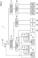
- FIG. 1 is a block diagram showing an air conditioner (10) according to a first embodiment of the present invention.
- the air conditioner (10) is installed in, e.g., a building, a factory, a condominium, or a separate house (hereinafter referred to as a building or the like), and performs air conditioning (cooling or heating) in an indoor space.
- a building or the like in which the air conditioner (10) is installed is supplied with electric power from an electric power system including an AC power source (70).
- Such a building or the like is provided with a distribution board (60) connected to the AC power source (70) and receiving AC power from the AC power source (70).
- the distribution board (60) includes a plurality of breakers, and distributes AC power from the AC power source (70) to a plurality of devices via the respective breakers.
- the air conditioner (10) is connected to one of the breakers.
- the air conditioner (10) is operated by the AC power supplied through the distribution board (60).
- a load (80) is also connected to the distribution board (60).
- the load (80) includes a circuit which can be a source of a harmonic current such as an inverter circuit.
- Examples of the load (80) include an elevator provided in a building, an illumination device such as an LED, and another air conditioner different from the air conditioner (10).
- the air conditioner (10) includes a refrigerant circuit (not shown) having a compressor, a power converter (11), and an active filter device (20).
- the power converter (11) is connected to the AC power source (70) via the distribution board (60).
- the power converter (11) includes a converter circuit and an inverter circuit which are not shown.
- the power converter (11) converts AC power, supplied to the power converter (11), into AC power having a desired frequency and a desired voltage.
- the converted AC power is supplied to the compressor (more specifically, an electric motor included in the compressor). This allows the compressor to operate and the refrigerant circuit to operate, such that air in the indoor space is conditioned.
- a harmonic current may be generated.
- This harmonic current may flow out to the AC power source (70) via a current path (hereinafter referred to as a power receiving path (12)) that supplies electric power from the distribution board (60) to the air conditioner (10).
- the amount of such a harmonic current flowing out to the AC power source (70) is generally regulated. Therefore, in the air conditioner (10), the active filter device (20) is used to reduce the harmonic current flowing out.
- an improvement in the fundamental power factor is required. In order to do so, the active filter device (20) according to this embodiment also has the function of improving the fundamental power factor.
- a configuration of the active filter device (20) will be described.
- the active filter device (20) is incorporated in the air conditioner (10), and has the function of counteracting a harmonic current appearing in the power receiving path (12) of the power converter (11).
- the active filter device (20) allows a current (compensation current) to flow so that a current in a current path connecting the AC power source (70) and the distribution board (60) together (hereinafter referred to as a "power receiving path (61)") approaches a sinusoidal wave.
- the active filter device (20) detects the harmonic current appearing in the power receiving path (12), generates a compensation current having a phase opposite to that of the detected harmonic current, and supplies the compensation current to the power receiving path (12) of the air conditioner (10).
- the harmonic current generated in the air conditioner (10) may increase to the maximum level when the load of the air conditioner (10) is largest (for example, at the time of the maximum output of cooling air). Therefore, in the active filter device (20), its ability (the amount of power which can be generated) is set in view of the largest harmonic current at the time of the maximum load of the air conditioner (10).
- the air conditioner (10) tends to be used at an intermediate load state rather than at the maximum load state. Therefore, the active filter device (20) whose ability is set in this way may have a long period of time in which its capacity is excessive during operation.
- the active filter device (20) has a function of improving the fundamental power factor.
- the active filter device (20) has a configuration so as to allow a compensation current which compensates for an invalid component of the fundamental wave to flow, thereby improving the fundamental power factor.
- the active filter device (20) according to this embodiment includes a current source (30) and a controller (40), as shown in FIG. 1 .
- the current source (30) generates a current (i.e., a compensation current) for reducing the harmonic current and improving the fundamental power factor.
- An output terminal of the current source (30) is connected to the power receiving path (12) of the power converter (11), and the compensation current generated is output to the power receiving path (12).
- the current source (30) in this embodiment includes a so-called inverter circuit.
- a switching command value (G) which will be described later is input to the current source (30), and the current source (30) generates a compensation current by performing switching in accordance with the switching command value (G).
- the controller (40) controls an output current of the current source (30).
- the controller (40) includes a first current value detector (41), a second current value detector (42), a phase detector (43), a first compensation portion calculation unit (44), a first current command calculation unit (45), a current source capacity storage unit (46), an excess calculation unit (47), a second compensation portion calculation unit (48), a second current command calculation unit (49), an adder (50), and a gate pulse generator (51).
- This controller (40) may include, e.g., a microcomputer and a memory device storing a program for operating the microcomputer.
- the first current value detector (41) detects a current value in the power receiving path (12) of the power converter (11). The current value detected by the first current value detector (41) is transmitted to the first compensation portion calculation unit (44).
- the first current value detector (41) may be configured as, but not limited to, a current transformer, for example.
- the first current value detector (41) may be configured to transmit a detection value in a wired system, or may be configured to transmit the detection value in a wireless system.
- the second current value detector (42) detects a current value in the power receiving path (61) connecting the AC power source (70) and the distribution board (60) together.
- the current value detected by the second current value detector (42) is transmitted to the second compensation portion calculation unit (48).
- the second current value detector (42) may be configured as, but not limited to, a current transformer, for example.
- the second current value detector (42) may be configured to transmit a detection value in a wired system, or may be configured to transmit the detection value in a wireless system. Further, the second current value detector (42) may be provided in the distribution board (60).
- the phase detector (43) detects a phase ( ⁇ t) of the current in the power receiving path (12), and transmits the detected phase ( ⁇ t) to the first and second compensation portion calculation units (44) and (48).
- the first compensation portion calculation unit (44) Based on the phase ( ⁇ t) detected by the phase detector (43) and the current value detected by the first current value detector (41), the first compensation portion calculation unit (44) obtains a value.
- the value indicates a current value required for compensating for the harmonic current in the power receiving path (12) (reducing the harmonic current) and compensating for the ineffective component of the fundamental wave (improving the fundamental power factor), and is hereinafter referred to as a "first compensation portion (i1)."
- the first compensation portion calculation unit (44) outputs the first compensation portion (i1) to the first current command calculation unit (45) and the excess calculation unit (47).
- the first current command calculation unit (45) generates a first current command value (i1*) according to the first compensation portion (i1), and outputs the first current command value (i1 *) to the adder (50). In this example, the first current command calculation unit (45) outputs the first compensation portion (i1) as the first current command value (i1*).
- the current source capacity storage unit (46) is configured as a part of a memory device constituting the controller (40).
- the current source capacity storage unit (46) stores the magnitude of a current that can be compensated by the active filter device (20), i.e., the maximum current value (e.g., a rated value) that can be output from the current source (30).
- the value stored in the current source capacity storage unit (46) is referred to as an "output current capacity (Cap).”
- the second compensation portion calculation unit (48) Based on the phase ( ⁇ t) detected by the phase detector (43) and the current value detected by the second current value detector (42), the second compensation portion calculation unit (48) obtains a value.
- the value indicates a current value required for compensating for the harmonic current in the power receiving path (61) (reducing the harmonic current) and compensating for the ineffective component of the fundamental wave (improving the fundamental power factor), and is hereinafter referred to as a "second compensation portion (i2)."
- the second compensation portion calculation unit (48) outputs the second compensation portion (i2) to the second current command calculation unit (49).
- the second current command calculation unit (49) generates a second current command value (i2*) according to the excess (res) and the second compensation portion (i2), and outputs the second current command value (i2*) to the adder (50). Specifically, the second current command calculation unit (49) of this embodiment generates the second current command value (i2*) in accordance with the following condition.
- the magnitude of the current for use in compensation is determined in accordance with the excess (res).
- the adder (50) adds the first current command value (i1 *) and the second current command value (i2*) to generate an additional value (hereinafter referred to as a "current command value (i*)"), and outputs the current command value (i*) to the gate pulse generator (51).
- the gate pulse generator (51) generates a switching command value (G) for instructing to perform switching in the inverter circuit constituting the current source (30). Specifically, the gate pulse generator (51) performs feedback control, i.e., repeating an operation of generating a switching command value (G) based on a deviation between an output current value of the current source (30) and the current command value (i*).
- the current source (30) supplies the power receiving path (12) with a current (compensation current) corresponding to the current command value (i*).
- the active filter device (20) supplies the power receiving path (12) with a compensation current obtained through superimposition of a current corresponding to the first current command value (i1 *) and a current corresponding to the second current command value (i2*).
- the active filter device (20) When the air conditioner (10) is started, the active filter device (20) is also active. Then, in the controller (40), the first compensation portion calculation unit (44) obtains the first compensation portion (i1) based on the phase ( ⁇ t) detected by the phase detector (43) and the current value detected by the first current value detector (41). Accordingly, the first current command calculation unit (45) generates the first current command value (i1*). Further, the second compensation portion calculation unit (48) obtains the second compensation portion (i2) based on the phase ( ⁇ t) detected by the phase detector (43) and the current value detected by the second current value detector (42).
- the second current command calculation unit (49) outputs the second compensation portion (i2) as the second current command value (i2*).
- the current command value (i*) generated by the adder (50) is a sum of the first compensation portion (i1) and the second compensation portion (i2).
- the gate pulse generator (51) when the current command value (i*) is generated, the gate pulse generator (51) generates the switching command value (G), and the current source (30) supplies the power receiving path (12) with the compensation current corresponding to the current command value (i*).
- the ability for compensation is not sufficiently excessive (if the second compensation portion (i2) ⁇ the excess (res))
- a current corresponding to the output current capacity (Cap) in other words, a current obtained through superimposition of the current corresponding to the detection value of the first current value detector (41) and the current corresponding to the excess (res)
- This case can reduce the harmonic current caused mainly by the power converter (11) and improve the fundamental power factor.
- Such a state may be, for example, a state in which the load of the air conditioner (10) is largest (for example, at the time of the maximum output of cooling air).
- the ability for compensation is sufficiently excessive (if the second compensation portion (i2) ⁇ the excess (res)), a current obtained through superimposition of the current corresponding to the detection value of the first current value detector (41) and the current corresponding to the detection value of the second current value detector (42) flows as a compensation current.
- This case can reduce the harmonic current caused not only by the air conditioner (10) but also by another load (80), and improve the fundamental power factor.
- An excess may be generated in the compensation ability of the active filter device (20) if, for example, the air conditioner (10) is used at an intermediate load state.
- this embodiment can reduce the harmonic current in a situation where the air conditioner (10) and another load are connected together. This embodiment can further improve the fundamental power factor.
- FIG. 2 is a block diagram showing an air conditioning system (1) according to a second embodiment.
- the air conditioning system (1) is provided with a plurality of air conditioners (10).
- Each of the air conditioners (10) includes a refrigerant circuit (not shown) having a compressor, a power converter (11), and an active filter device (20).
- the air conditioning system (1) includes a plurality of active filter devices (20).
- one active filter device (20) is incorporated into one air conditioner (10).
- Each active filter device (20) has substantially the same configuration as the active filter device (20) of the first embodiment.
- a mechanism for generating a second current command value (i2*) in this embodiment is different from that in the first embodiment.
- the active filter devices (20) in this embodiment generate the second current command value (i2 *) such that each of the active filter devices (20) generate a part of the second compensation portion (i2) in a shared manner.
- the active filter device (20) of this embodiment has a configuration in which a communication unit (52) is added to the active filter device (20) of the first embodiment, and the second current command calculation unit (49) has a modified function as described later.
- the controller (40) shown in FIG. 2 only the second compensation portion calculation unit (48) and the communication unit (52) are described, and the description of other components is omitted.
- all of the active filter devices (20) share the one second current value detector (42).
- an output (excess (res)) of the excess calculation unit (47) is input to the communication unit (52) in place of the second current command calculation unit (49). Then, the communication unit (52) of each active filter device (20) transmits the excess (res) obtained by the excess calculation unit (47) to the communication unit (52) of another active filter device (20), and receives the excess (res) transmitted from the communication unit (52) of the another active filter device (20). Communication between the communication units (52) may be implemented in a wired system or a wireless system.
- Each communication unit (52) outputs a signal indicating the excess (res) received from another communication unit (52) to the second current command calculation unit (49).
- Each second current command calculation unit (49) is configured to calculate the sum of the excess (res) of the entire air conditioning system (1) (hereinafter referred to as an "excess sum (S)") using the information of the excess (res) in another active filter device (20) obtained via the communication unit (52). Specifically, each second current command calculation unit (49) calculates the sum of all the excesses (res) of the respective active filter devices (20) received by all the communication units (52) except the associated communication unit (52) and the excesses (res) obtained by the associated excess calculation unit (47).
- each second current command calculation unit (49) calculates a share compensation portion (i3) that each active filter device (20) should generate a part of the second compensation portion (i2) in a shared manner based on the excess sum (S) and the second compensation portion (i2) obtained by the associated second compensation portion calculation unit (48). Specifically, in this embodiment, each of the second current command calculation units (49) generates the second current command value (i2*) in accordance with the following condition.
- the current of the second compensation portion (i2) is generated by the active filter devices (20) so as to be shared among the active filter devices (20).
- the compensation current may be shared equally among the active filter devices (20) or shared according to the ratio of the respective excesses (res) among the active filter devices (20).
- the second current command calculation unit (49) generates the second current command value (i2*) in accordance with the share compensation portion (i3).
- the second current command value (i2*) is generated, in each active filter device (20), the first current command value (i1 *) and the second current command value (i2*) are added in the same manner as in the active filter device (20) of the first embodiment, thereby generating a current command value (i*).
- a compensation current corresponding to the current command value (i*) is generated.
- each of the active filter devices (20) allows a current obtained through superimposition of a current corresponding to the detection value of the first current value detector (41) and a current corresponding to the respective excesses (res) to flow as a compensation current.
- a reduction in the harmonic current caused by each of the air conditioners (10) and an improvement in the fundamental power fundamental power factor are mainly performed.
- each of the active filter devices (20) allows a current through superimposition of a current corresponding to the detection value of the first current value detector (41) and a current corresponding to the share compensation portion (i3) to flow as a compensation current.
- the ability for compensation in the entire air conditioning system (1) is sufficiently excessive, it is possible to reduce the harmonic current caused not only by the air conditioners (10) but also by the other load (80) and to improve the fundamental power factor.
- this embodiment can reduce the harmonic current and improve the fundamental power factor in a situation where the air conditioner (10) and another load are connected together. Further, since compensation is shared among the active filter devices (20), this embodiment can reduce the harmonic current, more reliably.
- any one of the active filter devices (20) controls the operation of all other the active filter devices (20).
- any one of the active filter devices (20) may be configured to determine the share compensation portion (i3) in itself and the all other active filter devices (20) based on the excess sum (S), and transmit that information to the all other active filter devices (20), and the other active filter devices (20) may be configured to operate accordingly.
- FIG. 3 is a block diagram showing an air conditioning system (1) according to a third embodiment.
- a building or the like is supplied with electric power from an electric power system including an AC power source (hereinafter, referred to as a "high-voltage AC power source (100)") of high voltage (e.g., 6.6 kV).
- an alternating current received from the high-voltage AC power source (100) is converted into a single-phase alternating current having a lower voltage by a single-phase transformer (91), and is supplied to various loads (80).
- an alternating current from the high-voltage AC power source (100) is converted into a three-phase alternating current having a lower voltage than the alternating current by a three-phase transformer (90).
- the three-phase alternating current obtained through the three-phase transformer (90) is supplied to an air conditioner (10) and a load (80) via a distribution board (60), and is also supplied to another load (80) via a separate distribution board (60).
- a plurality of air conditioners (10) are provided which are supplied with a three-phase alternating current.
- Each air conditioner (10) is provided with an associated one of the active filter devices (20).
- Each of the active filter devices (20) is configured as a device independent from the air conditioner (10).
- the active filter device (20) does not necessarily need to be incorporated into the air conditioner (10) as in the above embodiments.
- the second current value detector (42) detects a current in the high-voltage AC power source (100). More specifically, the second current value detector (42) is connected to a point closer to the high-voltage AC power source (100) than a point of connection between the three-phase transformer (90) and the single-phase transformer (91) and the high-voltage AC power source (100).
- the detection value of the second current value detector (42) is transmitted to each of the active filter devices (20) in a wireless system.
- the detection value of the second current value detector (42) can be transmitted in a wired system.
- the first current value detector (41) is provided for each active filter device (20), and the respective active filter devices (20) detect the current of the power receiving path (12) in the air conditioner (10) corresponding to the active filter device (20).
- this embodiment can reduce a harmonic current in a situation where the air conditioner (10) and another load are connected together.
- This embodiment can further improve the fundamental power factor.
- the same or similar advantage can also be obtained if the configuration of this embodiment is modified so as to omit the system closer to the single-phase transformer (91).
- the active filter device (20) does not necessarily have to include the function of improving the fundamental power factor.
- the active filter device (20) may be configured to have only the function of reducing a harmonic current.
- the active filter device (20) may be configured to have only the function of improving the fundamental power factor.
- One air conditioner (10) may be provided with a plurality of active filter devices (20).
- the active filter devices (20) may generate a current of the second compensation portion (i2) in a shared manner.
- the present invention is useful as an active filter device, an air conditioner, and an air conditioning system.
Landscapes
- Engineering & Computer Science (AREA)
- Power Engineering (AREA)
- Electromagnetism (AREA)
- Automation & Control Theory (AREA)
- Radar, Positioning & Navigation (AREA)
- General Physics & Mathematics (AREA)
- Physics & Mathematics (AREA)
- Mechanical Engineering (AREA)
- General Engineering & Computer Science (AREA)
- Combustion & Propulsion (AREA)
- Chemical & Material Sciences (AREA)
- Supply And Distribution Of Alternating Current (AREA)
- Inverter Devices (AREA)
- Power Conversion In General (AREA)
- Rectifiers (AREA)
- Control Of Electrical Variables (AREA)
- Air Conditioning Control Device (AREA)
Description
- The present invention relates to an active filter device, an air conditioner, and an air conditioning system.
- In an air conditioner and other devices, an active filter device may be provided in order to prevent a harmonic current from flowing out into an electric power system (e.g., a power system including a commercial power source) (see, for example, Patent Document 1).
- Further, Patent Document 2 describes a device for supressing voltage fluctuation and higher harmonics of a power source system which supplies power to a load with large power fluctuation and large harmonic current.
- Further, Patent Document 3 is related to the technique which prevents permeation of the water into the electrical component unit provided in the outdoor unit. In order to solve the situation mentioned above, this invention is divided into the fan room containing a heat exchanger and a ventilation fan and the machine room which has an electrical component unit in which a compressor is arrange/positioned at the lower part and an electrically-wired part is accommodated in upper part by the partition plate standingly arranged inside the housing/casing.
- Non-Patent
Document 1 is a scientific paper describing parallel operation of inverter and active power filters in a distributed generation system. -
- [Patent Document 1]
Japanese Unexamined Patent Publication No. 2016-116330 - [Patent Document 2]
EP 0 610 058 A2 - [Patent Document 3]
JP 2015 055466 A - [Non-Patent Document 1] KHADEM S K et al: "Parallel operation of inverters and active power filters in distributed generation system - A review", XP 028120715
- However, a load (for example, an apparatus including, e.g., an inverter circuit such as an elevator) other than an air conditioner may be connected to an electric power system to which the air conditioner is connected. Such a load other than the air conditioner may be a source of a harmonic current. In this case, only dealing with the harmonic current from the air conditioner is insufficient, and it is desired to deal with the harmonic current from the air conditioner and the other devices. In addition, improvement in fundamental power factor is required in order to reduce, e.g., facility capacity and energy.
- In view of the foregoing background, it is therefore an object of the present invention to provide a technique of, in a situation where an air conditioner and another load are connected together, either or both reducing a harmonic current or improving a fundamental power factor.
- In order to solve the above problem, a first aspect of the present invention is directed to air conditioner according to
claim 1. - A second aspect is an air conditioning system according to claim 3.
- According to the first aspect, in a situation where the air conditioner and another load are connected together, it is possible to either or both reduce the harmonic current or improve the fundamental power factor.
- Further, in a situation where the air conditioner and another load are connected together, within a range corresponding to the ability of the current source (30), it is possible to either or both reduce the harmonic current or improve the fundamental power factor.
- In addition, an active filter device is easily installed.
- It is possible to obtain the above-described advantage by an active filter device incorporated in an air conditioner.
- Further, by using a plurality of active filter devices, it is possible to more reliably obtain the above-described advantage.
- It is possible to obtain the above-described advantage by an active filter device incorporated in an air conditioner.
-
- [
FIG. 1] FIG. 1 is a block diagram showing an air conditioner according to a first embodiment. - [
FIG. 2] FIG. 2 is a block diagram showing an air conditioning system according to a second embodiment. - [
FIG. 3] FIG. 3 is a block diagram showing an air conditioning system according to a third embodiment. - Embodiments of the present invention will be described in detail below with reference to the drawings. The embodiment described below is merely an exemplary one in nature, and is not intended to limit the scope, applications, or use of the invention.
-
FIG. 1 is a block diagram showing an air conditioner (10) according to a first embodiment of the present invention. The air conditioner (10) is installed in, e.g., a building, a factory, a condominium, or a separate house (hereinafter referred to as a building or the like), and performs air conditioning (cooling or heating) in an indoor space. A building or the like in which the air conditioner (10) is installed is supplied with electric power from an electric power system including an AC power source (70). Such a building or the like is provided with a distribution board (60) connected to the AC power source (70) and receiving AC power from the AC power source (70). The distribution board (60) includes a plurality of breakers, and distributes AC power from the AC power source (70) to a plurality of devices via the respective breakers. In this example, the air conditioner (10) is connected to one of the breakers. The air conditioner (10) is operated by the AC power supplied through the distribution board (60). - Further, in addition to the air conditioner (10), a load (80) is also connected to the distribution board (60). In this example, it is assumed that the load (80) includes a circuit which can be a source of a harmonic current such as an inverter circuit. Examples of the load (80) include an elevator provided in a building, an illumination device such as an LED, and another air conditioner different from the air conditioner (10).
- The air conditioner (10) includes a refrigerant circuit (not shown) having a compressor, a power converter (11), and an active filter device (20). The power converter (11) is connected to the AC power source (70) via the distribution board (60). The power converter (11) includes a converter circuit and an inverter circuit which are not shown. The power converter (11) converts AC power, supplied to the power converter (11), into AC power having a desired frequency and a desired voltage. The converted AC power is supplied to the compressor (more specifically, an electric motor included in the compressor). This allows the compressor to operate and the refrigerant circuit to operate, such that air in the indoor space is conditioned.
- When the power converter (11) and the electric motor in the compressor are operated in the air conditioner (10), a harmonic current may be generated. This harmonic current may flow out to the AC power source (70) via a current path (hereinafter referred to as a power receiving path (12)) that supplies electric power from the distribution board (60) to the air conditioner (10). The amount of such a harmonic current flowing out to the AC power source (70) is generally regulated. Therefore, in the air conditioner (10), the active filter device (20) is used to reduce the harmonic current flowing out. In addition, in view of facility capacity and energy saving, an improvement in the fundamental power factor is required. In order to do so, the active filter device (20) according to this embodiment also has the function of improving the fundamental power factor. Hereinafter, a configuration of the active filter device (20) will be described.
- The active filter device (20) is incorporated in the air conditioner (10), and has the function of counteracting a harmonic current appearing in the power receiving path (12) of the power converter (11). In other words, the active filter device (20) allows a current (compensation current) to flow so that a current in a current path connecting the AC power source (70) and the distribution board (60) together (hereinafter referred to as a "power receiving path (61)") approaches a sinusoidal wave. More specifically, the active filter device (20) detects the harmonic current appearing in the power receiving path (12), generates a compensation current having a phase opposite to that of the detected harmonic current, and supplies the compensation current to the power receiving path (12) of the air conditioner (10).
- The harmonic current generated in the air conditioner (10) may increase to the maximum level when the load of the air conditioner (10) is largest (for example, at the time of the maximum output of cooling air). Therefore, in the active filter device (20), its ability (the amount of power which can be generated) is set in view of the largest harmonic current at the time of the maximum load of the air conditioner (10). In general, the air conditioner (10) tends to be used at an intermediate load state rather than at the maximum load state. Therefore, the active filter device (20) whose ability is set in this way may have a long period of time in which its capacity is excessive during operation.
- In addition, the active filter device (20) has a function of improving the fundamental power factor. In this example, the active filter device (20) has a configuration so as to allow a compensation current which compensates for an invalid component of the fundamental wave to flow, thereby improving the fundamental power factor. In order to allow the active filter device (20) to perform these functions, the active filter device (20) according to this embodiment includes a current source (30) and a controller (40), as shown in
FIG. 1 . - The current source (30) generates a current (i.e., a compensation current) for reducing the harmonic current and improving the fundamental power factor. An output terminal of the current source (30) is connected to the power receiving path (12) of the power converter (11), and the compensation current generated is output to the power receiving path (12). The current source (30) in this embodiment includes a so-called inverter circuit. A switching command value (G) which will be described later is input to the current source (30), and the current source (30) generates a compensation current by performing switching in accordance with the switching command value (G).
- The controller (40) controls an output current of the current source (30). In this example, the controller (40) includes a first current value detector (41), a second current value detector (42), a phase detector (43), a first compensation portion calculation unit (44), a first current command calculation unit (45), a current source capacity storage unit (46), an excess calculation unit (47), a second compensation portion calculation unit (48), a second current command calculation unit (49), an adder (50), and a gate pulse generator (51). This controller (40) may include, e.g., a microcomputer and a memory device storing a program for operating the microcomputer.
- The first current value detector (41) detects a current value in the power receiving path (12) of the power converter (11). The current value detected by the first current value detector (41) is transmitted to the first compensation portion calculation unit (44). The first current value detector (41) may be configured as, but not limited to, a current transformer, for example. The first current value detector (41) may be configured to transmit a detection value in a wired system, or may be configured to transmit the detection value in a wireless system.
- The second current value detector (42) detects a current value in the power receiving path (61) connecting the AC power source (70) and the distribution board (60) together. The current value detected by the second current value detector (42) is transmitted to the second compensation portion calculation unit (48). The second current value detector (42) may be configured as, but not limited to, a current transformer, for example. The second current value detector (42) may be configured to transmit a detection value in a wired system, or may be configured to transmit the detection value in a wireless system. Further, the second current value detector (42) may be provided in the distribution board (60).
- The phase detector (43) detects a phase (ωt) of the current in the power receiving path (12), and transmits the detected phase (ωt) to the first and second compensation portion calculation units (44) and (48).
- Based on the phase (ωt) detected by the phase detector (43) and the current value detected by the first current value detector (41), the first compensation portion calculation unit (44) obtains a value. The value indicates a current value required for compensating for the harmonic current in the power receiving path (12) (reducing the harmonic current) and compensating for the ineffective component of the fundamental wave (improving the fundamental power factor), and is hereinafter referred to as a "first compensation portion (i1)." The first compensation portion calculation unit (44) outputs the first compensation portion (i1) to the first current command calculation unit (45) and the excess calculation unit (47).
- The first current command calculation unit (45) generates a first current command value (i1*) according to the first compensation portion (i1), and outputs the first current command value (i1 *) to the adder (50). In this example, the first current command calculation unit (45) outputs the first compensation portion (i1) as the first current command value (i1*).
- The current source capacity storage unit (46) is configured as a part of a memory device constituting the controller (40). The current source capacity storage unit (46) stores the magnitude of a current that can be compensated by the active filter device (20), i.e., the maximum current value (e.g., a rated value) that can be output from the current source (30). Here, the value stored in the current source capacity storage unit (46) is referred to as an "output current capacity (Cap)." Then, the excess calculation unit (47) obtains a difference (hereinafter referred to as an "excess (res)") between the output current capacity (Cap) and the first compensation portion (i1), and outputs the calculated excess (res) to the second current command calculation unit (49). That is, the excess (res) is shown as follows:

- Based on the phase (ωt) detected by the phase detector (43) and the current value detected by the second current value detector (42), the second compensation portion calculation unit (48) obtains a value. The value indicates a current value required for compensating for the harmonic current in the power receiving path (61) (reducing the harmonic current) and compensating for the ineffective component of the fundamental wave (improving the fundamental power factor), and is hereinafter referred to as a "second compensation portion (i2)." The second compensation portion calculation unit (48) outputs the second compensation portion (i2) to the second current command calculation unit (49).
- The second current command calculation unit (49) generates a second current command value (i2*) according to the excess (res) and the second compensation portion (i2), and outputs the second current command value (i2*) to the adder (50). Specifically, the second current command calculation unit (49) of this embodiment generates the second current command value (i2*) in accordance with the following condition.
-
- (1) If the second compensation portion (i2) ≥ the excess (res), the second current command value (i2*) = the excess (res).
- (2) If the second compensation portion (i2) < the excess (res), the second current command value (i2*) = the second compensation portion (i2).
- As can be seen, in this embodiment, the magnitude of the current for use in compensation is determined in accordance with the excess (res).
- The adder (50) adds the first current command value (i1 *) and the second current command value (i2*) to generate an additional value (hereinafter referred to as a "current command value (i*)"), and outputs the current command value (i*) to the gate pulse generator (51). The gate pulse generator (51) generates a switching command value (G) for instructing to perform switching in the inverter circuit constituting the current source (30). Specifically, the gate pulse generator (51) performs feedback control, i.e., repeating an operation of generating a switching command value (G) based on a deviation between an output current value of the current source (30) and the current command value (i*). As a result, the current source (30) supplies the power receiving path (12) with a current (compensation current) corresponding to the current command value (i*). In other words, the active filter device (20) supplies the power receiving path (12) with a compensation current obtained through superimposition of a current corresponding to the first current command value (i1 *) and a current corresponding to the second current command value (i2*).
- When the air conditioner (10) is started, the active filter device (20) is also active. Then, in the controller (40), the first compensation portion calculation unit (44) obtains the first compensation portion (i1) based on the phase (ωt) detected by the phase detector (43) and the current value detected by the first current value detector (41). Accordingly, the first current command calculation unit (45) generates the first current command value (i1*). Further, the second compensation portion calculation unit (48) obtains the second compensation portion (i2) based on the phase (ωt) detected by the phase detector (43) and the current value detected by the second current value detector (42).
- Then, the second current command calculation unit (49) generates the second current command value (i2*). For example, when the second compensation portion (i2) ≥ the excess (res) (if the ability for compensation is not sufficiently excessive), the second current command calculation unit (49) outputs the excess (res) as the second current command value (i2*) to the adder (50). Since the excess (res) = the output current capacity (Cap) - the first compensation portion (i1), the current command value (i*) generated by the adder (50) is the output current capacity (Cap).
- In addition, when the second compensation portion (i2) < the excess (res) (if the ability for compensation is sufficiently excessive), the second current command calculation unit (49) outputs the second compensation portion (i2) as the second current command value (i2*). As a result, the current command value (i*) generated by the adder (50) is a sum of the first compensation portion (i1) and the second compensation portion (i2).
- As can be seen, when the current command value (i*) is generated, the gate pulse generator (51) generates the switching command value (G), and the current source (30) supplies the power receiving path (12) with the compensation current corresponding to the current command value (i*). For example, if the ability for compensation is not sufficiently excessive (if the second compensation portion (i2) ≥ the excess (res)), a current corresponding to the output current capacity (Cap) (in other words, a current obtained through superimposition of the current corresponding to the detection value of the first current value detector (41) and the current corresponding to the excess (res)) flows as a compensation current. This case can reduce the harmonic current caused mainly by the power converter (11) and improve the fundamental power factor. Such a state may be, for example, a state in which the load of the air conditioner (10) is largest (for example, at the time of the maximum output of cooling air).
- On the other hand, if the ability for compensation is sufficiently excessive (if the second compensation portion (i2) < the excess (res)), a current obtained through superimposition of the current corresponding to the detection value of the first current value detector (41) and the current corresponding to the detection value of the second current value detector (42) flows as a compensation current. This case can reduce the harmonic current caused not only by the air conditioner (10) but also by another load (80), and improve the fundamental power factor. An excess may be generated in the compensation ability of the active filter device (20) if, for example, the air conditioner (10) is used at an intermediate load state.
- As described above, this embodiment can reduce the harmonic current in a situation where the air conditioner (10) and another load are connected together. This embodiment can further improve the fundamental power factor.
-
FIG. 2 is a block diagram showing an air conditioning system (1) according to a second embodiment. The air conditioning system (1) is provided with a plurality of air conditioners (10). Each of the air conditioners (10) includes a refrigerant circuit (not shown) having a compressor, a power converter (11), and an active filter device (20). In other words, the air conditioning system (1) includes a plurality of active filter devices (20). - In this example, one active filter device (20) is incorporated into one air conditioner (10). Each active filter device (20) has substantially the same configuration as the active filter device (20) of the first embodiment. However, a mechanism for generating a second current command value (i2*) in this embodiment is different from that in the first embodiment. The active filter devices (20) in this embodiment generate the second current command value (i2 *) such that each of the active filter devices (20) generate a part of the second compensation portion (i2) in a shared manner.
- In order to realize such sharing, the active filter device (20) of this embodiment has a configuration in which a communication unit (52) is added to the active filter device (20) of the first embodiment, and the second current command calculation unit (49) has a modified function as described later. In the controller (40) shown in
FIG. 2 , only the second compensation portion calculation unit (48) and the communication unit (52) are described, and the description of other components is omitted. Further, as shown inFIG. 2 , in the air conditioning system (1), all of the active filter devices (20) share the one second current value detector (42). - In the controller (40) of this embodiment, an output (excess (res)) of the excess calculation unit (47) is input to the communication unit (52) in place of the second current command calculation unit (49). Then, the communication unit (52) of each active filter device (20) transmits the excess (res) obtained by the excess calculation unit (47) to the communication unit (52) of another active filter device (20), and receives the excess (res) transmitted from the communication unit (52) of the another active filter device (20). Communication between the communication units (52) may be implemented in a wired system or a wireless system.
- Each communication unit (52) outputs a signal indicating the excess (res) received from another communication unit (52) to the second current command calculation unit (49). Each second current command calculation unit (49) is configured to calculate the sum of the excess (res) of the entire air conditioning system (1) (hereinafter referred to as an "excess sum (S)") using the information of the excess (res) in another active filter device (20) obtained via the communication unit (52). Specifically, each second current command calculation unit (49) calculates the sum of all the excesses (res) of the respective active filter devices (20) received by all the communication units (52) except the associated communication unit (52) and the excesses (res) obtained by the associated excess calculation unit (47).
- Further, each second current command calculation unit (49) calculates a share compensation portion (i3) that each active filter device (20) should generate a part of the second compensation portion (i2) in a shared manner based on the excess sum (S) and the second compensation portion (i2) obtained by the associated second compensation portion calculation unit (48). Specifically, in this embodiment, each of the second current command calculation units (49) generates the second current command value (i2*) in accordance with the following condition.
-
- (1) If the second compensation portion (i2) ≥ the excess (res), the share compensation portion (i3) = the excess (res) obtained by the associated excess calculation unit (47).
- (2) If the second compensation portion (i2) < the excess (res), the share compensation portion (i3) appropriately falls within the range of the second compensation portion (i2).
- In other words, in this embodiment, when the second compensation portion (i2) is smaller than the excess sum (S), the current of the second compensation portion (i2) is generated by the active filter devices (20) so as to be shared among the active filter devices (20). As a method of sharing compensation current within a range not exceeding the respective excesses (res), the compensation current may be shared equally among the active filter devices (20) or shared according to the ratio of the respective excesses (res) among the active filter devices (20).
- Once the share compensation portion (i3) in each active filter device (20) is obtained in this manner, in each active filter device (20), the second current command calculation unit (49) generates the second current command value (i2*) in accordance with the share compensation portion (i3). When the second current command value (i2*) is generated, in each active filter device (20), the first current command value (i1 *) and the second current command value (i2*) are added in the same manner as in the active filter device (20) of the first embodiment, thereby generating a current command value (i*). As a result, in each active filter device (20), a compensation current corresponding to the current command value (i*) is generated.
- For example, if the second compensation portion (i2) ≥ the excess sum (S) (if the ability for compensation in the entire air conditioning system (1) is not sufficiently excessive), each of the active filter devices (20) allows a current obtained through superimposition of a current corresponding to the detection value of the first current value detector (41) and a current corresponding to the respective excesses (res) to flow as a compensation current. In other words, if the ability for compensation in the entire air conditioning system (1) is not sufficiently excessive, a reduction in the harmonic current caused by each of the air conditioners (10) and an improvement in the fundamental power fundamental power factor are mainly performed.
- On the other hand, if the second compensation portion (i2) < the sum of the excess (S) (if the ability for compensation in the entire air conditioning system (1) is sufficiently excessive), each of the active filter devices (20) allows a current through superimposition of a current corresponding to the detection value of the first current value detector (41) and a current corresponding to the share compensation portion (i3) to flow as a compensation current. Thus, if the ability for compensation in the entire air conditioning system (1) is sufficiently excessive, it is possible to reduce the harmonic current caused not only by the air conditioners (10) but also by the other load (80) and to improve the fundamental power factor.
- As described above, even this embodiment can reduce the harmonic current and improve the fundamental power factor in a situation where the air conditioner (10) and another load are connected together. Further, since compensation is shared among the active filter devices (20), this embodiment can reduce the harmonic current, more reliably.
- In addition, the configuration of this embodiment can be changed so that any one of the active filter devices (20) controls the operation of all other the active filter devices (20). For example, any one of the active filter devices (20) may be configured to determine the share compensation portion (i3) in itself and the all other active filter devices (20) based on the excess sum (S), and transmit that information to the all other active filter devices (20), and the other active filter devices (20) may be configured to operate accordingly.
-
FIG. 3 is a block diagram showing an air conditioning system (1) according to a third embodiment. In this example, a building or the like is supplied with electric power from an electric power system including an AC power source (hereinafter, referred to as a "high-voltage AC power source (100)") of high voltage (e.g., 6.6 kV). In this building or the like, an alternating current received from the high-voltage AC power source (100) is converted into a single-phase alternating current having a lower voltage by a single-phase transformer (91), and is supplied to various loads (80). - Further, in this example, an alternating current from the high-voltage AC power source (100) is converted into a three-phase alternating current having a lower voltage than the alternating current by a three-phase transformer (90). The three-phase alternating current obtained through the three-phase transformer (90) is supplied to an air conditioner (10) and a load (80) via a distribution board (60), and is also supplied to another load (80) via a separate distribution board (60).
- In this example, as shown in
FIG. 3 , a plurality of air conditioners (10) are provided which are supplied with a three-phase alternating current. Each air conditioner (10) is provided with an associated one of the active filter devices (20). Each of the active filter devices (20) is configured as a device independent from the air conditioner (10). Thus, the active filter device (20) does not necessarily need to be incorporated into the air conditioner (10) as in the above embodiments. - Also, in this example, all of the active filter devices (20) share the one second current value detector (42). The second current value detector (42) detects a current in the high-voltage AC power source (100). More specifically, the second current value detector (42) is connected to a point closer to the high-voltage AC power source (100) than a point of connection between the three-phase transformer (90) and the single-phase transformer (91) and the high-voltage AC power source (100). The detection value of the second current value detector (42) is transmitted to each of the active filter devices (20) in a wireless system. Of course, the detection value of the second current value detector (42) can be transmitted in a wired system.
- The first current value detector (41) is provided for each active filter device (20), and the respective active filter devices (20) detect the current of the power receiving path (12) in the air conditioner (10) corresponding to the active filter device (20).
- Then, as in the second embodiment, the current of the second compensation portion (i2) is generated by the active filter devices (20) in a shared manner in this embodiment. Therefore, this embodiment can reduce a harmonic current in a situation where the air conditioner (10) and another load are connected together. This embodiment can further improve the fundamental power factor. In addition, the same or similar advantage can also be obtained if the configuration of this embodiment is modified so as to omit the system closer to the single-phase transformer (91).
- Note that the active filter device (20) does not necessarily have to include the function of improving the fundamental power factor. In other words, the active filter device (20) may be configured to have only the function of reducing a harmonic current. Instead, the active filter device (20) may be configured to have only the function of improving the fundamental power factor.
- One air conditioner (10) may be provided with a plurality of active filter devices (20). In this case, as in the second embodiment, the active filter devices (20) may generate a current of the second compensation portion (i2) in a shared manner.
- The present invention is useful as an active filter device, an air conditioner, and an air conditioning system.
-
- 1
- Air Conditioning System
- 10
- Air Conditioner
- 12
- Power Receiving Path
- 20
- Active Filter Device
- 30
- Current Source
- 40
- Controller
- 41
- First Current Value Detector
- 42
- Second Current Value Detector
- 60
- Distribution Board
- 61
- Power Receiving Path
Claims (3)
- An air conditioner including a refrigerant circuit having a compressor, a power converter (11), and an active filter device (20), wherein the air conditioner is configured to be supplied with electric power from an electric power system including an AC power source (70), the active filter device (20) is connected to the power converter (11) to be supplied with electric power from an AC power source (70) via a distribution board (60), and the active filter device (20) comprises:a current source (30) having an output connected to a first power receiving path (12) connecting the power converter (11) and the distribution board (60) , the current source (30) being configured to generate a current of a first compensation portion (i1) for either or both reducing a harmonic current in the power converter (11) or improving a fundamental power factor in the power converter (11);a first current sensor (41) configured to detect a current value in the first power receiving path (12) of the power converter (11);a second current sensor (42) configured to detect a current value in a second power receiving path connecting the AC power source (70) and the distribution board (60); anda controller (40) comprisinga phase detector (43) configured to detect a phase (ωt) of the current in the first power receiving path (12),a current source capacity storage unit (46) configured to store a maximum current (Cap) that can be output from the current source (30),an excess calculation unit (47) configured to calculate an excess as difference between the maximum current (Cap) and a first compensation portion (il) indicating a current value required for compensating for the harmonic current in the first power receiving path (12) and for compensating for the ineffective component of the fundamental wave and configured to output the calculated excess to a second current command calculation unit (49);a first compensation portion calculation unit (44) configured to determine, based on the phase (ωt) of the current in the first power receiving path (12) transmitted from the phase detector and the current value detected by the first current value detector (41), a first compensation portion (i1) indicative of a current value required for compensating the harmonic current in the power receiving path (12) and for compensating the ineffective component of the fundamental wave; a first current command calculation unit (45) configured to generate a first current command value according to the first compensation portion;a second compensation portion calculation unit (48) configured to determine, based on the phase (ωt) of the current in the first power receiving path (12) transmitted from the phase detector and the current value detected by the second current value detector (42), a second compensation portion (i2) indicative of a current value required for compensating the harmonic current in the second power receiving path (61) and for compensating the ineffective component of the fundamental wave;a second current command calculation unit (49) configured to generate a second current command value (i2*) according to the excess and the second compensation portion (i2) for output to an adder (50), whereinif the second compensation portion (i2) is larger or equal to the excess (res), then the second current command calculation unit (49) is configured to generate the second current command value (i2*) as being equal to the excess (res), andif the second compensation portion (i2) is lower the excess (res), then the second current command calculation unit (49) is configured to generate the second current command value (i2*) as being equal to the second compensation portion (i2); the adder (50) configured to add the first current command value (i1*) and the second current command value (i2*) to generate a current command value (i*); and ana gate pulse generator (51) receiving the current command value (i*) and configured to generate a switching control command (G) for instructing to perform feedback control to the current source (30) based on a deviation between an output current value of the current source (30) and the current command value (i*).
- The air conditioner of claim 1, wherein
at least one of the first current value detector (41) or the second current value detector (42) are configured to transmit the current value to the controller (40) in a wireless system. - Air conditioning system comprising a plurality of air conditioners, each air conditioner including a refrigerant circuit having a compressor, a power converter (11), and an active filter device (20), wherein each air conditioner is configured to be supplied with electric power from an electric power system including an AC power source (70), the active filter device (20) is connected to the power converter (11) to be supplied with electric power from an AC power source (70) via a distribution board (60), wherein the air conditioning system includes a shared current sensor (42) shared by the plurality of active filter devices (20), the shared current sensor (42) configured to detect a current value, each of the plurality of active filter devices (20) comprising:a current source (30) having an output connected to a first power receiving path (12) connecting the power converter (11) and the distribution board (60) , the current source (30) being configured to generate a current of a first compensation portion (i1) for either or both reducing a harmonic current in the power converter (11) or improving a fundamental power factor in the power converter (11);a first current sensor (41) configured to detect a current value in the first power receiving path (12) of the power converter (11); whereinthe shared current sensor (42) is configured to detect a current value in a second power receiving path connecting the AC power source (70) and the distribution board (60); anda controller (40) comprising:a phase detector (43) configured to detect a phase (ωt) of the current in the first power receiving path (12),a current source capacity storage unit (46) configured to store a maximum current (Cap) that can be output from the current source (30),an excess calculation unit (47) configured to calculate an excess as difference between the maximum current (Cap) and a first compensation portion (il) indicating a current value required for compensating for the harmonic current in the first power receiving path (12) and for compensating for the ineffective component of the fundamental wave and configured to output the calculated excess to a second current command calculation unit (49);a first compensation portion calculation unit (44) configured to determine, based on the phase (ωt) of the current in the first power receiving path (12) transmitted from the phase detector and the current value detected by the first current value detector (41), a first compensation portion (i1) indicative of a current value required for compensating the harmonic current in the first power receiving path (12) and for compensating the ineffective component of the fundamental wave;a communication unit (52) configured to transmit the excess (res) obtained by the excess calculation unit (47) to the communication unit (52) of another active filter device (20), and to receive the excess (res) transmitted from the communication unit (52) of the another active filter device (20);a first current command calculation unit (45) configured to generate a first current command value according to the first compensation portion,a second compensation portion calculation unit (48) configured to determine, based on the phase (ωt) of the current in the power receiving path (12) transmitted from the phase detector and the current value detected by the shared current value detector (42), a second compensation portion (i2) indicative of a current value required for compensating the harmonic current in the second power receiving path (61) and for compensating the ineffective component of the fundamental wave;the second current command calculation unit (49) configured to generate a second current command value (i2*) according to the excess and the second compensation portion (i2) for output to an adder (50), whereinthe second current command calculation unit (49) is configured to calculate an excess sum (S) corresponding to the sum of the excess (res) of the entire air conditioning system (1) using the information of the excess (res) in another active filter device (20) obtained via the communication unit (52);the second current command calculation unit (49) is configured to calculate a share compensation portion (i3) that each active filter device (20) should generate a part of the second compensation portion (i2) in a shared manner based on the excess sum (S) and the second compensation portion (i2) obtained by the associated second compensation portion calculation unit (48); andthe second current command calculation unit (49) is configured to generate a second current command value (i2*) in accordance with the share compensation portion (i3); the adder (50) configured to add the first current command value (i1*) and the second current command value (i2*) to generate a current command value (i*); and ana gate pulse generator (51) receiving the current command value (i*) and configured to generate a switching control command (G) for instructing to perform feedback control to the current source (30) based on a deviation between an output current value of the current source (30) and the current command value (i*).
Applications Claiming Priority (2)
| Application Number | Priority Date | Filing Date | Title |
|---|---|---|---|
| JP2016192803A JP6299831B1 (en) | 2016-09-30 | 2016-09-30 | Active filter device, air conditioning device, and air conditioning system |
| PCT/JP2017/025280 WO2018061403A1 (en) | 2016-09-30 | 2017-07-11 | Active filter device, air conditioning device, and air conditioning system |
Publications (3)
| Publication Number | Publication Date |
|---|---|
| EP3511797A1 EP3511797A1 (en) | 2019-07-17 |
| EP3511797A4 EP3511797A4 (en) | 2020-06-03 |
| EP3511797B1 true EP3511797B1 (en) | 2024-11-06 |
Family
ID=61756513
Family Applications (1)
| Application Number | Title | Priority Date | Filing Date |
|---|---|---|---|
| EP17855361.6A Active EP3511797B1 (en) | 2016-09-30 | 2017-07-11 | Active filter device, air conditioning device, and air conditioning system |
Country Status (6)
| Country | Link |
|---|---|
| US (1) | US10797584B2 (en) |
| EP (1) | EP3511797B1 (en) |
| JP (1) | JP6299831B1 (en) |
| CN (1) | CN109643138B (en) |
| AU (1) | AU2017336736B2 (en) |
| WO (1) | WO2018061403A1 (en) |
Families Citing this family (8)
| Publication number | Priority date | Publication date | Assignee | Title |
|---|---|---|---|---|
| EP3620886A4 (en) * | 2017-05-30 | 2020-09-23 | Daikin Industries, Ltd. | POWER QUALITY MANAGEMENT SYSTEM AND AIR CONDITIONING |
| JP7279309B2 (en) * | 2018-07-12 | 2023-05-23 | 富士電機株式会社 | power converter |
| CN109193656A (en) * | 2018-09-19 | 2019-01-11 | 山东新升光电科技有限责任公司 | Crystal growing furnace power quality distributed compensation and quality-improving method |
| JP6819731B2 (en) | 2019-06-24 | 2021-01-27 | ダイキン工業株式会社 | Air conditioner |
| EP3930160A1 (en) * | 2020-06-23 | 2021-12-29 | ABB Power Grids Switzerland AG | Converter, method of installing a power system, and use of a converter |
| CN112054661B (en) * | 2020-10-12 | 2023-06-27 | 四川科陆新能电气有限公司 | Harmonic suppression static quantity output control method for single-phase electric system |
| CN112648693B (en) * | 2020-12-18 | 2023-08-04 | 青岛海信日立空调系统有限公司 | A kind of control method of air conditioner and multi-channel PFC circuit |
| JP7206532B1 (en) | 2021-10-05 | 2023-01-18 | ダイキン工業株式会社 | Air conditioner and control system |
Family Cites Families (25)
| Publication number | Priority date | Publication date | Assignee | Title |
|---|---|---|---|---|
| JPS63277427A (en) * | 1987-05-07 | 1988-11-15 | Mitsubishi Electric Corp | Active type reactive-power compensator |
| JPS6485574A (en) * | 1987-09-28 | 1989-03-30 | Toshiba Corp | Power converting device |
| US5345375A (en) * | 1991-12-16 | 1994-09-06 | Regents Of The University Of Minnesota | System and method for reducing harmonic currents by current injection |
| US5499178A (en) * | 1991-12-16 | 1996-03-12 | Regents Of The University Of Minnesota | System for reducing harmonics by harmonic current injection |
| JP3130694B2 (en) | 1993-02-04 | 2001-01-31 | 株式会社東芝 | Voltage fluctuation and harmonic suppression device |
| JP2585796Y2 (en) * | 1993-11-26 | 1998-11-25 | 日新電機株式会社 | Active filter |
| JPH08140267A (en) * | 1994-11-08 | 1996-05-31 | Toshiba Corp | Active filter device |
| JP3459303B2 (en) * | 1994-12-22 | 2003-10-20 | 株式会社東芝 | Distributed power system |
| JP2002199588A (en) * | 2000-12-27 | 2002-07-12 | Hitachi Ltd | Power system |
| TWI236792B (en) * | 2004-08-30 | 2005-07-21 | Uis Abler Electronics Co Ltd | Active equipment for harmonic suppression |
| JP4992225B2 (en) * | 2005-11-04 | 2012-08-08 | 株式会社富士通ゼネラル | Power supply |
| JP4779777B2 (en) | 2006-04-06 | 2011-09-28 | 株式会社日立製作所 | Flicker suppression device |
| TWI347058B (en) * | 2007-03-05 | 2011-08-11 | Ablerex Electronics Co Ltd | Active power filter apparatus |
| KR101533560B1 (en) * | 2008-09-22 | 2015-07-09 | 삼성전자 주식회사 | 3-phase power factor compensation device and its control method |
| WO2010045726A1 (en) * | 2008-10-20 | 2010-04-29 | Deborah Lynn Fallis | Single phase power factor correction system and method |
| US8674544B2 (en) * | 2009-01-26 | 2014-03-18 | Geneva Cleantech, Inc. | Methods and apparatus for power factor correction and reduction of distortion in and noise in a power supply delivery network |
| JP5321119B2 (en) * | 2009-02-19 | 2013-10-23 | 富士電機株式会社 | Reactive power compensator and control method of reactive power compensator |
| WO2011034253A1 (en) * | 2009-09-15 | 2011-03-24 | 한국전기안전공사 | Remote electrical safety diagnosis system and apparatus |
| CN201758287U (en) * | 2010-08-24 | 2011-03-09 | 北京金恒科讯节能科技有限公司 | Low-voltage active power filter |
| JP5585643B2 (en) * | 2012-12-14 | 2014-09-10 | ダイキン工業株式会社 | Active filter control device |
| US9099916B2 (en) * | 2013-01-02 | 2015-08-04 | Tci, Llc | Paralleling of active filters with independent controls |
| JP6137480B2 (en) | 2013-09-13 | 2017-05-31 | 株式会社富士通ゼネラル | Air conditioner outdoor unit |
| JP6112103B2 (en) * | 2014-12-15 | 2017-04-12 | ダイキン工業株式会社 | Control device for parallel type active filter |
| JP6274287B1 (en) * | 2016-09-30 | 2018-02-07 | ダイキン工業株式会社 | Current estimation device |
| WO2018105737A1 (en) * | 2016-12-09 | 2018-06-14 | ダイキン工業株式会社 | Device with built-in active filter |
-
2016
- 2016-09-30 JP JP2016192803A patent/JP6299831B1/en active Active
-
2017
- 2017-07-11 CN CN201780052479.5A patent/CN109643138B/en active Active
- 2017-07-11 WO PCT/JP2017/025280 patent/WO2018061403A1/en not_active Ceased
- 2017-07-11 US US16/335,745 patent/US10797584B2/en active Active
- 2017-07-11 EP EP17855361.6A patent/EP3511797B1/en active Active
- 2017-07-11 AU AU2017336736A patent/AU2017336736B2/en active Active
Also Published As
| Publication number | Publication date |
|---|---|
| JP2018057201A (en) | 2018-04-05 |
| WO2018061403A1 (en) | 2018-04-05 |
| US20190238046A1 (en) | 2019-08-01 |
| AU2017336736A1 (en) | 2019-05-02 |
| EP3511797A4 (en) | 2020-06-03 |
| AU2017336736B2 (en) | 2020-10-22 |
| US10797584B2 (en) | 2020-10-06 |
| CN109643138B (en) | 2020-11-20 |
| CN109643138A (en) | 2019-04-16 |
| JP6299831B1 (en) | 2018-03-28 |
| EP3511797A1 (en) | 2019-07-17 |
Similar Documents
| Publication | Publication Date | Title |
|---|---|---|
| EP3511797B1 (en) | Active filter device, air conditioning device, and air conditioning system | |
| US10651651B2 (en) | Device with built-in active filter | |
| AU2018276600B2 (en) | Power Source Quality Management System and Air Conditioner | |
| CA2944371A1 (en) | Cooling device, in particular for cooling components housed in a switchgear cabinet, corresponding use, and corresponding method | |
| AU2019245978B2 (en) | Power source quality management system and air conditioning apparatus | |
| US11577186B2 (en) | Active filter system and air conditioning device | |
| JP2012213283A (en) | Power generation system | |
| JP2018191374A (en) | Active filter device and air-conditioner using the same | |
| JP6834753B2 (en) | Active filter device and air conditioner using it | |
| JP6834754B2 (en) | Active filter device and air conditioner using it | |
| JP6415732B2 (en) | Air conditioning system | |
| JP7789332B1 (en) | Control devices, power conditioners, heat pump systems and electrical equipment | |
| JP2019022344A (en) | Active filter system, air conditioner | |
| JP7044984B2 (en) | Power quality control system and air conditioner | |
| JP2019022344A5 (en) | ||
| KR20190090541A (en) | Motor driving apparatus and air conditioner comprising the same | |
| KR20190040424A (en) | Power quality conditioner | |
| JP2015173558A (en) | Power supply system |
Legal Events
| Date | Code | Title | Description |
|---|---|---|---|
| STAA | Information on the status of an ep patent application or granted ep patent |
Free format text: STATUS: THE INTERNATIONAL PUBLICATION HAS BEEN MADE |
|
| PUAI | Public reference made under article 153(3) epc to a published international application that has entered the european phase |
Free format text: ORIGINAL CODE: 0009012 |
|
| STAA | Information on the status of an ep patent application or granted ep patent |
Free format text: STATUS: REQUEST FOR EXAMINATION WAS MADE |
|
| 17P | Request for examination filed |
Effective date: 20190412 |
|
| AK | Designated contracting states |
Kind code of ref document: A1 Designated state(s): AL AT BE BG CH CY CZ DE DK EE ES FI FR GB GR HR HU IE IS IT LI LT LU LV MC MK MT NL NO PL PT RO RS SE SI SK SM TR |
|
| AX | Request for extension of the european patent |
Extension state: BA ME |
|
| DAV | Request for validation of the european patent (deleted) | ||
| DAX | Request for extension of the european patent (deleted) | ||
| A4 | Supplementary search report drawn up and despatched |
Effective date: 20200507 |
|
| RIC1 | Information provided on ipc code assigned before grant |
Ipc: H02M 7/48 20070101ALI20200429BHEP Ipc: G05F 1/70 20060101AFI20200429BHEP Ipc: H02M 1/12 20060101ALI20200429BHEP Ipc: H02M 7/12 20060101ALI20200429BHEP Ipc: H02M 1/42 20070101ALI20200429BHEP |
|
| STAA | Information on the status of an ep patent application or granted ep patent |
Free format text: STATUS: EXAMINATION IS IN PROGRESS |
|
| 17Q | First examination report despatched |
Effective date: 20211011 |
|
| RAP3 | Party data changed (applicant data changed or rights of an application transferred) |
Owner name: DAIKIN INDUSTRIES, LTD. |
|
| P01 | Opt-out of the competence of the unified patent court (upc) registered |
Effective date: 20230525 |
|
| REG | Reference to a national code |
Ref country code: DE Ref legal event code: R079 Free format text: PREVIOUS MAIN CLASS: G05F0001700000 Ipc: H02J0003180000 Ref country code: DE Ref legal event code: R079 Ref document number: 602017085995 Country of ref document: DE Free format text: PREVIOUS MAIN CLASS: G05F0001700000 Ipc: H02J0003180000 |
|
| GRAP | Despatch of communication of intention to grant a patent |
Free format text: ORIGINAL CODE: EPIDOSNIGR1 |
|
| STAA | Information on the status of an ep patent application or granted ep patent |
Free format text: STATUS: GRANT OF PATENT IS INTENDED |
|
| RIC1 | Information provided on ipc code assigned before grant |
Ipc: H02M 7/48 20070101ALI20240607BHEP Ipc: H02M 7/12 20060101ALI20240607BHEP Ipc: H02M 1/42 20070101ALI20240607BHEP Ipc: H02M 1/12 20060101ALI20240607BHEP Ipc: G05F 1/70 20060101ALI20240607BHEP Ipc: H02J 3/18 20060101AFI20240607BHEP |
|
| INTG | Intention to grant announced |
Effective date: 20240627 |
|
| GRAS | Grant fee paid |
Free format text: ORIGINAL CODE: EPIDOSNIGR3 |
|
| GRAA | (expected) grant |
Free format text: ORIGINAL CODE: 0009210 |
|
| STAA | Information on the status of an ep patent application or granted ep patent |
Free format text: STATUS: THE PATENT HAS BEEN GRANTED |
|
| AK | Designated contracting states |
Kind code of ref document: B1 Designated state(s): AL AT BE BG CH CY CZ DE DK EE ES FI FR GB GR HR HU IE IS IT LI LT LU LV MC MK MT NL NO PL PT RO RS SE SI SK SM TR |
|
| REG | Reference to a national code |
Ref country code: GB Ref legal event code: FG4D |
|
| REG | Reference to a national code |
Ref country code: CH Ref legal event code: EP |
|
| REG | Reference to a national code |
Ref country code: DE Ref legal event code: R096 Ref document number: 602017085995 Country of ref document: DE |
|
| REG | Reference to a national code |
Ref country code: IE Ref legal event code: FG4D |
|
| REG | Reference to a national code |
Ref country code: LT Ref legal event code: MG9D |
|
| REG | Reference to a national code |
Ref country code: NL Ref legal event code: MP Effective date: 20241106 |
|
| PG25 | Lapsed in a contracting state [announced via postgrant information from national office to epo] |
Ref country code: HR Free format text: LAPSE BECAUSE OF FAILURE TO SUBMIT A TRANSLATION OF THE DESCRIPTION OR TO PAY THE FEE WITHIN THE PRESCRIBED TIME-LIMIT Effective date: 20241106 Ref country code: PT Free format text: LAPSE BECAUSE OF FAILURE TO SUBMIT A TRANSLATION OF THE DESCRIPTION OR TO PAY THE FEE WITHIN THE PRESCRIBED TIME-LIMIT Effective date: 20250306 Ref country code: IS Free format text: LAPSE BECAUSE OF FAILURE TO SUBMIT A TRANSLATION OF THE DESCRIPTION OR TO PAY THE FEE WITHIN THE PRESCRIBED TIME-LIMIT Effective date: 20250306 |
|
| PG25 | Lapsed in a contracting state [announced via postgrant information from national office to epo] |
Ref country code: FI Free format text: LAPSE BECAUSE OF FAILURE TO SUBMIT A TRANSLATION OF THE DESCRIPTION OR TO PAY THE FEE WITHIN THE PRESCRIBED TIME-LIMIT Effective date: 20241106 Ref country code: NL Free format text: LAPSE BECAUSE OF FAILURE TO SUBMIT A TRANSLATION OF THE DESCRIPTION OR TO PAY THE FEE WITHIN THE PRESCRIBED TIME-LIMIT Effective date: 20241106 |
|
| REG | Reference to a national code |
Ref country code: AT Ref legal event code: MK05 Ref document number: 1740459 Country of ref document: AT Kind code of ref document: T Effective date: 20241106 |
|
| PG25 | Lapsed in a contracting state [announced via postgrant information from national office to epo] |
Ref country code: BG Free format text: LAPSE BECAUSE OF FAILURE TO SUBMIT A TRANSLATION OF THE DESCRIPTION OR TO PAY THE FEE WITHIN THE PRESCRIBED TIME-LIMIT Effective date: 20241106 |
|
| PG25 | Lapsed in a contracting state [announced via postgrant information from national office to epo] |
Ref country code: ES Free format text: LAPSE BECAUSE OF FAILURE TO SUBMIT A TRANSLATION OF THE DESCRIPTION OR TO PAY THE FEE WITHIN THE PRESCRIBED TIME-LIMIT Effective date: 20241106 |
|
| PG25 | Lapsed in a contracting state [announced via postgrant information from national office to epo] |
Ref country code: NO Free format text: LAPSE BECAUSE OF FAILURE TO SUBMIT A TRANSLATION OF THE DESCRIPTION OR TO PAY THE FEE WITHIN THE PRESCRIBED TIME-LIMIT Effective date: 20250206 |
|
| PG25 | Lapsed in a contracting state [announced via postgrant information from national office to epo] |
Ref country code: LV Free format text: LAPSE BECAUSE OF FAILURE TO SUBMIT A TRANSLATION OF THE DESCRIPTION OR TO PAY THE FEE WITHIN THE PRESCRIBED TIME-LIMIT Effective date: 20241106 Ref country code: GR Free format text: LAPSE BECAUSE OF FAILURE TO SUBMIT A TRANSLATION OF THE DESCRIPTION OR TO PAY THE FEE WITHIN THE PRESCRIBED TIME-LIMIT Effective date: 20250207 Ref country code: AT Free format text: LAPSE BECAUSE OF FAILURE TO SUBMIT A TRANSLATION OF THE DESCRIPTION OR TO PAY THE FEE WITHIN THE PRESCRIBED TIME-LIMIT Effective date: 20241106 |
|
| PG25 | Lapsed in a contracting state [announced via postgrant information from national office to epo] |
Ref country code: PL Free format text: LAPSE BECAUSE OF FAILURE TO SUBMIT A TRANSLATION OF THE DESCRIPTION OR TO PAY THE FEE WITHIN THE PRESCRIBED TIME-LIMIT Effective date: 20241106 |
|
| PG25 | Lapsed in a contracting state [announced via postgrant information from national office to epo] |
Ref country code: RS Free format text: LAPSE BECAUSE OF FAILURE TO SUBMIT A TRANSLATION OF THE DESCRIPTION OR TO PAY THE FEE WITHIN THE PRESCRIBED TIME-LIMIT Effective date: 20250206 |
|
| PG25 | Lapsed in a contracting state [announced via postgrant information from national office to epo] |
Ref country code: SM Free format text: LAPSE BECAUSE OF FAILURE TO SUBMIT A TRANSLATION OF THE DESCRIPTION OR TO PAY THE FEE WITHIN THE PRESCRIBED TIME-LIMIT Effective date: 20241106 |
|
| PG25 | Lapsed in a contracting state [announced via postgrant information from national office to epo] |
Ref country code: DK Free format text: LAPSE BECAUSE OF FAILURE TO SUBMIT A TRANSLATION OF THE DESCRIPTION OR TO PAY THE FEE WITHIN THE PRESCRIBED TIME-LIMIT Effective date: 20241106 |
|
| PG25 | Lapsed in a contracting state [announced via postgrant information from national office to epo] |
Ref country code: EE Free format text: LAPSE BECAUSE OF FAILURE TO SUBMIT A TRANSLATION OF THE DESCRIPTION OR TO PAY THE FEE WITHIN THE PRESCRIBED TIME-LIMIT Effective date: 20241106 |
|
| PG25 | Lapsed in a contracting state [announced via postgrant information from national office to epo] |
Ref country code: RO Free format text: LAPSE BECAUSE OF FAILURE TO SUBMIT A TRANSLATION OF THE DESCRIPTION OR TO PAY THE FEE WITHIN THE PRESCRIBED TIME-LIMIT Effective date: 20241106 |
|
| PG25 | Lapsed in a contracting state [announced via postgrant information from national office to epo] |
Ref country code: SK Free format text: LAPSE BECAUSE OF FAILURE TO SUBMIT A TRANSLATION OF THE DESCRIPTION OR TO PAY THE FEE WITHIN THE PRESCRIBED TIME-LIMIT Effective date: 20241106 |
|
| PG25 | Lapsed in a contracting state [announced via postgrant information from national office to epo] |
Ref country code: CZ Free format text: LAPSE BECAUSE OF FAILURE TO SUBMIT A TRANSLATION OF THE DESCRIPTION OR TO PAY THE FEE WITHIN THE PRESCRIBED TIME-LIMIT Effective date: 20241106 |
|
| PG25 | Lapsed in a contracting state [announced via postgrant information from national office to epo] |
Ref country code: IT Free format text: LAPSE BECAUSE OF FAILURE TO SUBMIT A TRANSLATION OF THE DESCRIPTION OR TO PAY THE FEE WITHIN THE PRESCRIBED TIME-LIMIT Effective date: 20241106 |
|
| REG | Reference to a national code |
Ref country code: DE Ref legal event code: R097 Ref document number: 602017085995 Country of ref document: DE |
|
| PG25 | Lapsed in a contracting state [announced via postgrant information from national office to epo] |
Ref country code: SE Free format text: LAPSE BECAUSE OF FAILURE TO SUBMIT A TRANSLATION OF THE DESCRIPTION OR TO PAY THE FEE WITHIN THE PRESCRIBED TIME-LIMIT Effective date: 20241106 |
|
| PLBE | No opposition filed within time limit |
Free format text: ORIGINAL CODE: 0009261 |
|
| STAA | Information on the status of an ep patent application or granted ep patent |
Free format text: STATUS: NO OPPOSITION FILED WITHIN TIME LIMIT |
|
| PGFP | Annual fee paid to national office [announced via postgrant information from national office to epo] |
Ref country code: DE Payment date: 20250722 Year of fee payment: 9 |
|
| 26N | No opposition filed |
Effective date: 20250807 |
|
| PGFP | Annual fee paid to national office [announced via postgrant information from national office to epo] |
Ref country code: GB Payment date: 20250722 Year of fee payment: 9 |
|
| PGFP | Annual fee paid to national office [announced via postgrant information from national office to epo] |
Ref country code: FR Payment date: 20250725 Year of fee payment: 9 |
|
| REG | Reference to a national code |
Ref country code: CH Ref legal event code: H13 Free format text: ST27 STATUS EVENT CODE: U-0-0-H10-H13 (AS PROVIDED BY THE NATIONAL OFFICE) Effective date: 20260224 |
|
| PG25 | Lapsed in a contracting state [announced via postgrant information from national office to epo] |
Ref country code: LU Free format text: LAPSE BECAUSE OF NON-PAYMENT OF DUE FEES Effective date: 20250711 |
|
| REG | Reference to a national code |
Ref country code: BE Ref legal event code: MM Effective date: 20250731 |
|
| PG25 | Lapsed in a contracting state [announced via postgrant information from national office to epo] |
Ref country code: BE Free format text: LAPSE BECAUSE OF NON-PAYMENT OF DUE FEES Effective date: 20250731 |
|
| PG25 | Lapsed in a contracting state [announced via postgrant information from national office to epo] |
Ref country code: CH Free format text: LAPSE BECAUSE OF NON-PAYMENT OF DUE FEES Effective date: 20250731 |