EP3511626A1 - Method for resizing holes - Google Patents
Method for resizing holes Download PDFInfo
- Publication number
- EP3511626A1 EP3511626A1 EP19151474.4A EP19151474A EP3511626A1 EP 3511626 A1 EP3511626 A1 EP 3511626A1 EP 19151474 A EP19151474 A EP 19151474A EP 3511626 A1 EP3511626 A1 EP 3511626A1
- Authority
- EP
- European Patent Office
- Prior art keywords
- hole
- rivet
- existing
- turbine component
- new
- Prior art date
- Legal status (The legal status is an assumption and is not a legal conclusion. Google has not performed a legal analysis and makes no representation as to the accuracy of the status listed.)
- Withdrawn
Links
Images



Classifications
-
- B—PERFORMING OPERATIONS; TRANSPORTING
- B23—MACHINE TOOLS; METAL-WORKING NOT OTHERWISE PROVIDED FOR
- B23P—METAL-WORKING NOT OTHERWISE PROVIDED FOR; COMBINED OPERATIONS; UNIVERSAL MACHINE TOOLS
- B23P6/00—Restoring or reconditioning objects
- B23P6/002—Repairing turbine components, e.g. moving or stationary blades, rotors
- B23P6/007—Repairing turbine components, e.g. moving or stationary blades, rotors using only additive methods, e.g. build-up welding
-
- B—PERFORMING OPERATIONS; TRANSPORTING
- B21—MECHANICAL METAL-WORKING WITHOUT ESSENTIALLY REMOVING MATERIAL; PUNCHING METAL
- B21J—FORGING; HAMMERING; PRESSING METAL; RIVETING; FORGE FURNACES
- B21J15/00—Riveting
- B21J15/02—Riveting procedures
- B21J15/08—Riveting by applying heat, e.g. to the end parts of the rivets to enable heads to be formed
-
- B—PERFORMING OPERATIONS; TRANSPORTING
- B23—MACHINE TOOLS; METAL-WORKING NOT OTHERWISE PROVIDED FOR
- B23P—METAL-WORKING NOT OTHERWISE PROVIDED FOR; COMBINED OPERATIONS; UNIVERSAL MACHINE TOOLS
- B23P6/00—Restoring or reconditioning objects
- B23P6/002—Repairing turbine components, e.g. moving or stationary blades, rotors
-
- F—MECHANICAL ENGINEERING; LIGHTING; HEATING; WEAPONS; BLASTING
- F01—MACHINES OR ENGINES IN GENERAL; ENGINE PLANTS IN GENERAL; STEAM ENGINES
- F01D—NON-POSITIVE DISPLACEMENT MACHINES OR ENGINES, e.g. STEAM TURBINES
- F01D9/00—Stators
- F01D9/06—Fluid supply conduits to nozzles or the like
- F01D9/065—Fluid supply or removal conduits traversing the working fluid flow, e.g. for lubrication-, cooling-, or sealing fluids
-
- F—MECHANICAL ENGINEERING; LIGHTING; HEATING; WEAPONS; BLASTING
- F02—COMBUSTION ENGINES; HOT-GAS OR COMBUSTION-PRODUCT ENGINE PLANTS
- F02C—GAS-TURBINE PLANTS; AIR INTAKES FOR JET-PROPULSION PLANTS; CONTROLLING FUEL SUPPLY IN AIR-BREATHING JET-PROPULSION PLANTS
- F02C7/00—Features, components parts, details or accessories, not provided for in, or of interest apart form groups F02C1/00 - F02C6/00; Air intakes for jet-propulsion plants
- F02C7/22—Fuel supply systems
- F02C7/232—Fuel valves; Draining valves or systems
-
- F—MECHANICAL ENGINEERING; LIGHTING; HEATING; WEAPONS; BLASTING
- F02—COMBUSTION ENGINES; HOT-GAS OR COMBUSTION-PRODUCT ENGINE PLANTS
- F02C—GAS-TURBINE PLANTS; AIR INTAKES FOR JET-PROPULSION PLANTS; CONTROLLING FUEL SUPPLY IN AIR-BREATHING JET-PROPULSION PLANTS
- F02C9/00—Controlling gas-turbine plants; Controlling fuel supply in air- breathing jet-propulsion plants
- F02C9/26—Control of fuel supply
- F02C9/32—Control of fuel supply characterised by throttling of fuel
-
- F—MECHANICAL ENGINEERING; LIGHTING; HEATING; WEAPONS; BLASTING
- F23—COMBUSTION APPARATUS; COMBUSTION PROCESSES
- F23D—BURNERS
- F23D99/00—Subject matter not provided for in other groups of this subclass
-
- F—MECHANICAL ENGINEERING; LIGHTING; HEATING; WEAPONS; BLASTING
- F23—COMBUSTION APPARATUS; COMBUSTION PROCESSES
- F23R—GENERATING COMBUSTION PRODUCTS OF HIGH PRESSURE OR HIGH VELOCITY, e.g. GAS-TURBINE COMBUSTION CHAMBERS
- F23R3/00—Continuous combustion chambers using liquid or gaseous fuel
- F23R3/28—Continuous combustion chambers using liquid or gaseous fuel characterised by the fuel supply
- F23R3/283—Attaching or cooling of fuel injecting means including supports for fuel injectors, stems, or lances
-
- B—PERFORMING OPERATIONS; TRANSPORTING
- B23—MACHINE TOOLS; METAL-WORKING NOT OTHERWISE PROVIDED FOR
- B23H—WORKING OF METAL BY THE ACTION OF A HIGH CONCENTRATION OF ELECTRIC CURRENT ON A WORKPIECE USING AN ELECTRODE WHICH TAKES THE PLACE OF A TOOL; SUCH WORKING COMBINED WITH OTHER FORMS OF WORKING OF METAL
- B23H1/00—Electrical discharge machining, i.e. removing metal with a series of rapidly recurring electrical discharges between an electrode and a workpiece in the presence of a fluid dielectric
-
- B—PERFORMING OPERATIONS; TRANSPORTING
- B23—MACHINE TOOLS; METAL-WORKING NOT OTHERWISE PROVIDED FOR
- B23K—SOLDERING OR UNSOLDERING; WELDING; CLADDING OR PLATING BY SOLDERING OR WELDING; CUTTING BY APPLYING HEAT LOCALLY, e.g. FLAME CUTTING; WORKING BY LASER BEAM
- B23K11/00—Resistance welding; Severing by resistance heating
- B23K11/002—Resistance welding; Severing by resistance heating specially adapted for particular articles or work
- B23K11/004—Welding of a small piece to a large or broad piece
- B23K11/0066—Riveting
-
- B—PERFORMING OPERATIONS; TRANSPORTING
- B23—MACHINE TOOLS; METAL-WORKING NOT OTHERWISE PROVIDED FOR
- B23P—METAL-WORKING NOT OTHERWISE PROVIDED FOR; COMBINED OPERATIONS; UNIVERSAL MACHINE TOOLS
- B23P2700/00—Indexing scheme relating to the articles being treated, e.g. manufactured, repaired, assembled, connected or other operations covered in the subgroups
- B23P2700/13—Parts of turbine combustion chambers
-
- F—MECHANICAL ENGINEERING; LIGHTING; HEATING; WEAPONS; BLASTING
- F05—INDEXING SCHEMES RELATING TO ENGINES OR PUMPS IN VARIOUS SUBCLASSES OF CLASSES F01-F04
- F05D—INDEXING SCHEME FOR ASPECTS RELATING TO NON-POSITIVE-DISPLACEMENT MACHINES OR ENGINES, GAS-TURBINES OR JET-PROPULSION PLANTS
- F05D2230/00—Manufacture
- F05D2230/80—Repairing, retrofitting or upgrading methods
-
- F—MECHANICAL ENGINEERING; LIGHTING; HEATING; WEAPONS; BLASTING
- F05—INDEXING SCHEMES RELATING TO ENGINES OR PUMPS IN VARIOUS SUBCLASSES OF CLASSES F01-F04
- F05D—INDEXING SCHEME FOR ASPECTS RELATING TO NON-POSITIVE-DISPLACEMENT MACHINES OR ENGINES, GAS-TURBINES OR JET-PROPULSION PLANTS
- F05D2240/00—Components
- F05D2240/35—Combustors or associated equipment
-
- F—MECHANICAL ENGINEERING; LIGHTING; HEATING; WEAPONS; BLASTING
- F23—COMBUSTION APPARATUS; COMBUSTION PROCESSES
- F23R—GENERATING COMBUSTION PRODUCTS OF HIGH PRESSURE OR HIGH VELOCITY, e.g. GAS-TURBINE COMBUSTION CHAMBERS
- F23R2900/00—Special features of, or arrangements for continuous combustion chambers; Combustion processes therefor
- F23R2900/00019—Repairing or maintaining combustion chamber liners or subparts
Definitions
- the present application and the resultant patent relate generally to gas turbine engines and more particularly relate to systems and methods for resizing existing holes such as premix fuel inlet holes within a vane turbine fuel nozzle assembly in a fast, efficient, and safe manner.
- a combustor in gas turbine engines, includes a number of fuel nozzles.
- the fuel nozzles typically include a subassembly of generally concentric tubes defining a central passage for supplying diffusion fuel gas and a pair of concentric passages for supplying premix fuel gas.
- Spaced from and surrounding the subassembly may be an inlet flow conditioner for directing and confining a flow of inlet air past a number of circumferentially spaced vanes carried by the subassembly.
- the vanes may be in communication with the concentric fuel gas supply passages.
- the vanes may include outer and inner premix fuel supply holes for supplying gas from the respective passages for mixing with the flow of inlet air.
- the air-fuel gas mixture may be swirled by the vanes downstream of the premix fuel supply holes for subsequent combustion in a combustion chamber.
- the fuel supply holes may be sized to achieve a predetermined pressure drop for a specific fuel energy content and may have a specific radial/axial pattern that achieves a radial fuel-to-air ratio that is favorable for overall combustor performance. If the energy content of the fuel increases, the hole sizes may need to be decreased. If it is desired to change the hole pattern on a nozzle, the hole positions also may change. To decrease the fuel hole size or change the overall hole pattern, the holes may be machined open and a cylinder of metal may be brazed into place before the new holes are installed. For repeatability, the cylinder outside diameter should be large enough to leave a sufficient segment of the cylinder perimeter after the new hole is installed when taking into account the original and final hole positions in addition to the cylinder outside diameter tolerances. The replacement piece, however, may be expensive and the overall process may produce excessive amounts of scrap as well as unneeded or outdated inventory.
- the present application and the resultant patent thus provide a method of filling an existing hole in a surface of a turbine component.
- the method may include the steps of enlarging the existing hole, placing a rivet into the enlarged hole, welding the rivet into place, and grinding the rivet to be flush with the surface of the turbine component.
- the present application and the resultant patent further provide a method of replacing an existing fuel supply hole in a vane of a fuel nozzle assembly.
- the method may include the steps of enlarging the existing hole, placing a rivet into the enlarged hole, fusion welding the rivet into place, grinding the rivet to be flush with the vane, and machining a new fuel supply hole in the vane.
- the new fuel supply hole is smaller than the existing fuel supply hole.
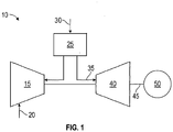
- Fig. 1 shows a schematic diagram of gas turbine engine 10 as may be used herein.
- the gas turbine engine 10 may include a compressor 15.
- the compressor 15 compresses an incoming flow of air 20.
- the compressor 15 delivers the compressed flow of air 20 to a combustor 25.
- the combustor 25 mixes the compressed flow of air 20 with a pressurized flow of fuel 30 and ignites the mixture to create a flow of hot combustion gases 35.
- the gas turbine engine 10 may include any number of combustors 25.
- the flow of hot combustion gases 35 is in turn delivered to a turbine 40.
- the flow of hot combustion gases 35 drives the turbine 40 so as to produce mechanical work.
- the mechanical work produced in the turbine 40 drives the compressor 15 via a shaft 45 and an external load 50 such as an electrical generator and the like.
- the gas turbine engine 10 may use natural gas, various types of syngas, liquid fuels, and/or other types of fuels and blends thereof.
- the gas turbine engine 10 may be any one of a number of different gas turbine engines offered by General Electric Company of Schenectady, New York, including, but not limited to, those such as a 7 or a 9 series heavy duty gas turbine engine and the like.
- the gas turbine engine 10 may have different configurations and may use other types of components. Other types of gas turbine engines also may be used herein. Multiple gas turbine engines, other types of turbines, and other types of power generation equipment also may be used herein together.
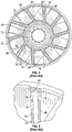
- Figs. 2-4 represent an example of a conventional fuel nozzle assembly 55 that may be used with the gas turbine engine 10.
- the fuel nozzle assembly 55 may include a subassembly 60 and a surrounding air inlet conditioner 62.
- the subassembly 60 may include a central tube 64 and a pair of concentric tubes 66 and 68 defining therebetween discrete annular fuel passages 70 and 72.
- the central tube 64 supplies diffusion gas to a combustion zone (not shown) located downstream of the fuel nozzle assembly 55.
- the subassembly 60 further includes a number of vanes 74 that are shown in Fig. 2 as circumferentially spaced from each other around the outer tube 68.
- the vanes 74 may include outer premix fuel supply holes 76 supplied with gaseous fuel from the passage 72 and a number of inner premix fuel supply holes 78 supplied with gaseous fuel from the passage 70.
- Each vane 74 may have a pair of outer and inner plenums 80 and 82, respectively, confined between opposite side walls 84 and 86 of the vane 74.
- the holes 76 and 78 may be fluidically connected with the passages 72 and 70 through the outer and inner plenums 80 and 82, respectively.
- the outer premix fuel supply holes 76 may include a pair of the radially spaced premix fuel supply holes 76 through one wall 84 of the vane 74 and a single premix fuel supply hole 76 through the opposite side wall 86 of the vane 74. Downstream portions 88 of the vanes 74 may impart a swirl to the flow of premixed air and gaseous fuel flowing between the subassembly 60 and the inlet flow conditioner 62, the gaseous fuel being supplied to the air stream via the outer and inner premix fuel supply holes 76 and 78, respectively.
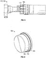
- Figs. 5-12 show exemplary systems and method steps in resizing a hole 100 such as the fuel supply holes 76 in a turbine component 110 such as a vane 115 of a fuel nozzle assembly 120. Other types of surfaces 125 also may be used herein.
- the existing holes 76 may be enlarged by plunge electrical discharge machining (EDM), a drill or ream process, and similar techniques.
- EDM plunge electrical discharge machining
- replacement rivets 150 may be fabricated.
- the rivets 150 may have a body 160, a flange 170, and an upper cap 180. The size and shape of the rivets 150 may vary.
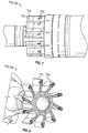
- the rivets 150 may be made from the same or similar high temperature material alloys as the components of the fuel nozzle assembly 120. At Figs. 7 and 8 and step 190, the rivets 150 may be pressed into the enlarged holes 185 until the rivets 150 are largely flush with the surface 125 of the vane 115. At Fig. 9 and step 200, the rivets 150 may be fusion welded into place within the enlarged hole 185. Other types of joining techniques may be used herein. At Fig. 10 and step 210, the cap 180 of the rivet 150 may be ground down to be flush with the surface 125 of the vane 115. Other types of finishing techniques may be used herein.
- the new holes 100 may be machined in the vane 115.
- the size, number, and location of the holes 100 may be varied from the original configuration. Specifically, any number of the holes 110 may be created in any suitable size, shape, or configuration.
- the holes 100 may be created via a plunge EDM process as above or via similar machining techniques. Other components and other configurations may be used herein.
- the resizing steps described herein thus allows an upgraded configuration to the vanes 115 of the fuel nozzle assembly 120 or other type of turbine component 110. Moreover, unwanted fuel nozzle inventory may be retrofitted with vanes 115 having useful hole sizes and configurations and returned to service.
- the resultant fuel nozzle assembly 120 thus may have comparable or even improved dynamics, flame holding, emissions, and the like.
- the use of the custom rivets 150 provides consistent hole to hole flow repeatability.
Landscapes
- Engineering & Computer Science (AREA)
- Mechanical Engineering (AREA)
- Chemical & Material Sciences (AREA)
- Combustion & Propulsion (AREA)
- General Engineering & Computer Science (AREA)
- Physics & Mathematics (AREA)
- Fluid Mechanics (AREA)
- Turbine Rotor Nozzle Sealing (AREA)
Abstract
The present application thus provides a method of filling an existing hole (76) in a surface (125) of a turbine component (110). The method may include the steps of enlarging the existing hole (76), placing a rivet into the enlarged hole (185), welding the rivet (150) into place, and grinding the rivet (150) to be flush with the surface (125) of the turbine component (110).
Description
- The present application and the resultant patent relate generally to gas turbine engines and more particularly relate to systems and methods for resizing existing holes such as premix fuel inlet holes within a vane turbine fuel nozzle assembly in a fast, efficient, and safe manner.
- In gas turbine engines, a combustor includes a number of fuel nozzles. The fuel nozzles typically include a subassembly of generally concentric tubes defining a central passage for supplying diffusion fuel gas and a pair of concentric passages for supplying premix fuel gas. Spaced from and surrounding the subassembly may be an inlet flow conditioner for directing and confining a flow of inlet air past a number of circumferentially spaced vanes carried by the subassembly. The vanes may be in communication with the concentric fuel gas supply passages. Particularly, the vanes may include outer and inner premix fuel supply holes for supplying gas from the respective passages for mixing with the flow of inlet air. The air-fuel gas mixture may be swirled by the vanes downstream of the premix fuel supply holes for subsequent combustion in a combustion chamber.
- The fuel supply holes may be sized to achieve a predetermined pressure drop for a specific fuel energy content and may have a specific radial/axial pattern that achieves a radial fuel-to-air ratio that is favorable for overall combustor performance. If the energy content of the fuel increases, the hole sizes may need to be decreased. If it is desired to change the hole pattern on a nozzle, the hole positions also may change. To decrease the fuel hole size or change the overall hole pattern, the holes may be machined open and a cylinder of metal may be brazed into place before the new holes are installed. For repeatability, the cylinder outside diameter should be large enough to leave a sufficient segment of the cylinder perimeter after the new hole is installed when taking into account the original and final hole positions in addition to the cylinder outside diameter tolerances. The replacement piece, however, may be expensive and the overall process may produce excessive amounts of scrap as well as unneeded or outdated inventory.
- The present application and the resultant patent thus provide a method of filling an existing hole in a surface of a turbine component. The method may include the steps of enlarging the existing hole, placing a rivet into the enlarged hole, welding the rivet into place, and grinding the rivet to be flush with the surface of the turbine component.
- The present application and the resultant patent further provide a method of replacing an existing fuel supply hole in a vane of a fuel nozzle assembly. The method may include the steps of enlarging the existing hole, placing a rivet into the enlarged hole, fusion welding the rivet into place, grinding the rivet to be flush with the vane, and machining a new fuel supply hole in the vane. The new fuel supply hole is smaller than the existing fuel supply hole.
- These and other features and improvements of the present application and the resultant patent will become apparent to one of ordinary skill in the art upon review of the following detailed description when taken in conjunction with the several drawings and the appended claims.
-
-
Fig. 1 is a schematic diagram of a gas turbine engine showing a compressor, a combustor, a turbine, and a load. -
Fig. 2 is a sectional view of a fuel nozzle assembly that may be used with the gas turbine engine ofFig. 1 . -
Fig. 3 is a sectional view taken along line 3-3 ofFig. 2 showing the vanes of the fuel nozzle assembly. -
Fig. 4 is an enlarged view of one of the vanes of the fuel nozzle assembly ofFig. 3 . -
Fig. 5 is a side view of a fuel nozzle assembly to be repaired according to the method steps described herein. -
Fig. 6 is a perspective view of a rivet used to repair the fuel nozzle assembly ofFig. 5 -
Fig. 7 is a perspective view of a portion of the fuel nozzle assembly ofFig. 5 . -
Fig. 8 is a further perspective view of a portion of the fuel nozzle assembly ofFig. 5 . -
Fig. 9 is a further perspective view of a portion of the fuel nozzle assembly ofFig. 5 . -
Fig. 10 is a further perspective view of a portion of the fuel nozzle assembly ofFig. 5 . -
Fig. 11 is a further perspective view of a portion of the fuel nozzle assembly ofFig. 5 as repaired herein. -
Fig. 12 is a flow chart showing exemplary method steps in the repair of the fuel nozzle assembly ofFig. 5 . - Referring now to the drawings, in which like numerals refer to like elements throughout the several views,
Fig. 1 shows a schematic diagram ofgas turbine engine 10 as may be used herein. Thegas turbine engine 10 may include acompressor 15. Thecompressor 15 compresses an incoming flow ofair 20. Thecompressor 15 delivers the compressed flow ofair 20 to a combustor 25. The combustor 25 mixes the compressed flow ofair 20 with a pressurized flow offuel 30 and ignites the mixture to create a flow ofhot combustion gases 35. Although only a single combustor 25 is shown, thegas turbine engine 10 may include any number of combustors 25. The flow ofhot combustion gases 35 is in turn delivered to aturbine 40. The flow ofhot combustion gases 35 drives theturbine 40 so as to produce mechanical work. The mechanical work produced in theturbine 40 drives thecompressor 15 via ashaft 45 and anexternal load 50 such as an electrical generator and the like. - The
gas turbine engine 10 may use natural gas, various types of syngas, liquid fuels, and/or other types of fuels and blends thereof. Thegas turbine engine 10 may be any one of a number of different gas turbine engines offered by General Electric Company of Schenectady, New York, including, but not limited to, those such as a 7 or a 9 series heavy duty gas turbine engine and the like. Thegas turbine engine 10 may have different configurations and may use other types of components. Other types of gas turbine engines also may be used herein. Multiple gas turbine engines, other types of turbines, and other types of power generation equipment also may be used herein together. -
Figs. 2-4 represent an example of a conventionalfuel nozzle assembly 55 that may be used with thegas turbine engine 10. Generally, thefuel nozzle assembly 55 may include asubassembly 60 and a surroundingair inlet conditioner 62. Thesubassembly 60 may include acentral tube 64 and a pair ofconcentric tubes annular fuel passages central tube 64 supplies diffusion gas to a combustion zone (not shown) located downstream of thefuel nozzle assembly 55. Thesubassembly 60 further includes a number ofvanes 74 that are shown inFig. 2 as circumferentially spaced from each other around theouter tube 68. Thevanes 74 may include outer premixfuel supply holes 76 supplied with gaseous fuel from thepassage 72 and a number of inner premixfuel supply holes 78 supplied with gaseous fuel from thepassage 70. Eachvane 74 may have a pair of outer andinner plenums opposite side walls vane 74. Theholes passages inner plenums - The outer premix
fuel supply holes 76 may include a pair of the radially spaced premixfuel supply holes 76 through onewall 84 of thevane 74 and a single premixfuel supply hole 76 through theopposite side wall 86 of thevane 74.Downstream portions 88 of thevanes 74 may impart a swirl to the flow of premixed air and gaseous fuel flowing between thesubassembly 60 and theinlet flow conditioner 62, the gaseous fuel being supplied to the air stream via the outer and inner premixfuel supply holes -
Figs. 5-12 show exemplary systems and method steps in resizing ahole 100 such as thefuel supply holes 76 in a turbine component 110 such as avane 115 of a fuel nozzle assembly 120. Other types ofsurfaces 125 also may be used herein. AtFig. 5 andstep 130, the existingholes 76 may be enlarged by plunge electrical discharge machining (EDM), a drill or ream process, and similar techniques. Atstep 140,replacement rivets 150 may be fabricated. As is shown inFig. 6 , therivets 150 may have abody 160, aflange 170, and anupper cap 180. The size and shape of therivets 150 may vary. Therivets 150 may be made from the same or similar high temperature material alloys as the components of the fuel nozzle assembly 120. AtFigs. 7 and 8 and step 190, therivets 150 may be pressed into theenlarged holes 185 until therivets 150 are largely flush with thesurface 125 of thevane 115. AtFig. 9 and step 200, therivets 150 may be fusion welded into place within theenlarged hole 185. Other types of joining techniques may be used herein. AtFig. 10 andstep 210, thecap 180 of therivet 150 may be ground down to be flush with thesurface 125 of thevane 115. Other types of finishing techniques may be used herein. - At
Fig. 11 andstep 220, thenew holes 100 may be machined in thevane 115. The size, number, and location of theholes 100 may be varied from the original configuration. Specifically, any number of the holes 110 may be created in any suitable size, shape, or configuration. Theholes 100 may be created via a plunge EDM process as above or via similar machining techniques. Other components and other configurations may be used herein. - The resizing steps described herein thus allows an upgraded configuration to the
vanes 115 of the fuel nozzle assembly 120 or other type of turbine component 110. Moreover, unwanted fuel nozzle inventory may be retrofitted withvanes 115 having useful hole sizes and configurations and returned to service. The resultant fuel nozzle assembly 120 thus may have comparable or even improved dynamics, flame holding, emissions, and the like. As opposed to the known expensive brazed cylindrical plugs and aluminide closure methods, the use of the custom rivets 150 provides consistent hole to hole flow repeatability. - It should be apparent that the foregoing relates only to certain embodiments of the present application and the resultant patent. Numerous changes and modifications may be made herein by one of ordinary skill in the art without departing from the general spirit and scope of the invention as defined by the following claims and the equivalents thereof.
Claims (15)
- A method of filling an existing hole (76) in a surface (125) of a turbine component (110), comprising:enlarging the existing hole (76);placing a rivet (150) into the enlarged hole (185);welding the rivet (150) into place; andgrinding the rivet (150) to be flush with the surface (125) of the turbine component (110).
- The method of claim 1, wherein the step of filling an existing hole (76) in a surface (125) of a turbine component (110) comprises filing an existing hole (76) in a vane (115) of a fuel nozzle assembly (120).
- The method of claim 1, wherein the step of enlarging the existing hole (76) comprises an electronic discharge machining process.
- The method of claim 1, wherein the step of enlarging the existing hole (76) comprises a drill or a ream process.
- The method of claim 1, further comprising the step of fabricating the rivet (150).
- The method of claim 5, wherein the step of fabricating the rivet (150) comprises fabricating the rivet (150) with a body (160), a flange (170), and a cap (180).
- The method of claim 1, wherein the step of placing the rivet (150) into the enlarged hole (185) comprising placing the rivet (150) into the enlarged hole (185) until the rivet (150) is flush with the surface (125).
- The method of claim 1, wherein the rivet (150) comprises a body (160) and a cap (180) and wherein the step of welding the rivet (150) into place comprises fusion welding the cap (180) to the surface (125).
- The method of claim 1, wherein the rivet (150) comprises a body (160) and a cap (180) and wherein the step of grinding the rivet (150) to be flush with the surface (125) of the turbine component (110) comprises grinding the cap (180) of the rivet (150).
- The method of claim 1, further comprising machining a new hole (100) in the surface (125) of the turbine component (110).
- The method of claim 10, wherein the step of machining a new hole (100) in the surface (125) of the turbine component (110) comprises an electronic discharge machining process.
- The method of claim 10, wherein the step of machining a new hole (100) in the surface (125) of the turbine component (110) comprises machining a plurality of new holes (100) in the surface (125) of the turbine component (110).
- The method of claim 10, wherein the existing hole (76) comprises a first size, wherein comprises new hole (100) has a second size, and wherein the second size is smaller than the first size.
- The method of claim 10, wherein the existing hole (75) comprises a first position, wherein the new hole (100) comprises a second position, and wherein the second position is different than the first position.
- A method of replacing an existing fuel supply hole (76) in a vane (115) of a fuel nozzle assembly (120), comprising:enlarging the existing hole (76);placing a rivet (150) into the enlarged hole (185);fusion welding the rivet (150) into place;grinding the rivet (150) to be flush with the vane (115); andmachining a new fuel supply hole (100) in the vane (115);wherein the new fuel supply hole (100) is smaller than the existing fuel supply hole (76).
Applications Claiming Priority (1)
| Application Number | Priority Date | Filing Date | Title |
|---|---|---|---|
| US15/872,424 US20190217429A1 (en) | 2018-01-16 | 2018-01-16 | Systems and methods for resizing holes |
Publications (1)
| Publication Number | Publication Date |
|---|---|
| EP3511626A1 true EP3511626A1 (en) | 2019-07-17 |
Family
ID=65019429
Family Applications (1)
| Application Number | Title | Priority Date | Filing Date |
|---|---|---|---|
| EP19151474.4A Withdrawn EP3511626A1 (en) | 2018-01-16 | 2019-01-11 | Method for resizing holes |
Country Status (3)
| Country | Link |
|---|---|
| US (1) | US20190217429A1 (en) |
| EP (1) | EP3511626A1 (en) |
| CN (1) | CN110043372A (en) |
Citations (7)
| Publication number | Priority date | Publication date | Assignee | Title |
|---|---|---|---|---|
| US2010569A (en) * | 1934-03-28 | 1935-08-06 | Florence Pipe Foundry & Machin | Method of plugging holes in plates |
| US5343619A (en) * | 1992-09-02 | 1994-09-06 | Societe Nationale D'etude Et De Construction De Moteurs D'aviation "S.N.E.C.M.A." | Hollow blade for a turbomachine and method of manufacturing said blade |
| DE4415341A1 (en) * | 1994-05-02 | 1995-11-09 | Teves Gmbh Alfred | Closing device for closing pressure-carrying channels in a housing |
| US6370752B1 (en) * | 2000-04-21 | 2002-04-16 | General Electric Company | Method for repositioning or repairing holes |
| US20050278930A1 (en) * | 2004-06-22 | 2005-12-22 | Szuba Philip S | Method and apparatus for orientating a fastening element |
| US7377036B2 (en) * | 2004-10-05 | 2008-05-27 | General Electric Company | Methods for tuning fuel injection assemblies for a gas turbine fuel nozzle |
| US20140124100A1 (en) * | 2012-11-06 | 2014-05-08 | General Electric Company | Methods of resizing holes |
Family Cites Families (11)
| Publication number | Priority date | Publication date | Assignee | Title |
|---|---|---|---|---|
| US3626568A (en) * | 1969-04-23 | 1971-12-14 | Avco Corp | Method for bonding pins into holes in a hollow turbine blade |
| GB2073641B (en) * | 1980-04-15 | 1984-09-19 | Inoue Japax Res | Controlling crater shape in electrical discharge machining |
| US6615470B2 (en) * | 1997-12-15 | 2003-09-09 | General Electric Company | System and method for repairing cast articles |
| CN1789651B (en) * | 1999-02-11 | 2010-06-16 | 菲利浦石油公司 | Cutting component used for hydraulic underreamer |
| US6883700B2 (en) * | 2002-09-26 | 2005-04-26 | Siemens Westinghouse Power Corporation | Turbine blade closure system |
| US9404374B2 (en) * | 2008-04-09 | 2016-08-02 | United Technologies Corporation | Trunnion hole repair utilizing interference fit inserts |
| US8510925B2 (en) * | 2008-09-04 | 2013-08-20 | Rolls-Royce Corporation | System and method for sealing vacuum in hollow fan blades |
| US20140174091A1 (en) * | 2012-12-21 | 2014-06-26 | United Technologies Corporation | Repair procedure for a gas turbine engine via variable polarity welding |
| US20140331477A1 (en) * | 2013-05-07 | 2014-11-13 | The Boeing Company | Flush fastener design and installation |
| WO2015026798A1 (en) * | 2013-08-20 | 2015-02-26 | United Technologies Corporation | Replacing an aperture with an annular bushing in a composite laminated composite component |
| US9593595B2 (en) * | 2014-04-14 | 2017-03-14 | Solar Turbines Incorporated | Method of remanufacturing a machine component |
-
2018
- 2018-01-16 US US15/872,424 patent/US20190217429A1/en not_active Abandoned
-
2019
- 2019-01-11 EP EP19151474.4A patent/EP3511626A1/en not_active Withdrawn
- 2019-01-16 CN CN201910039918.XA patent/CN110043372A/en active Pending
Patent Citations (7)
| Publication number | Priority date | Publication date | Assignee | Title |
|---|---|---|---|---|
| US2010569A (en) * | 1934-03-28 | 1935-08-06 | Florence Pipe Foundry & Machin | Method of plugging holes in plates |
| US5343619A (en) * | 1992-09-02 | 1994-09-06 | Societe Nationale D'etude Et De Construction De Moteurs D'aviation "S.N.E.C.M.A." | Hollow blade for a turbomachine and method of manufacturing said blade |
| DE4415341A1 (en) * | 1994-05-02 | 1995-11-09 | Teves Gmbh Alfred | Closing device for closing pressure-carrying channels in a housing |
| US6370752B1 (en) * | 2000-04-21 | 2002-04-16 | General Electric Company | Method for repositioning or repairing holes |
| US20050278930A1 (en) * | 2004-06-22 | 2005-12-22 | Szuba Philip S | Method and apparatus for orientating a fastening element |
| US7377036B2 (en) * | 2004-10-05 | 2008-05-27 | General Electric Company | Methods for tuning fuel injection assemblies for a gas turbine fuel nozzle |
| US20140124100A1 (en) * | 2012-11-06 | 2014-05-08 | General Electric Company | Methods of resizing holes |
Also Published As
| Publication number | Publication date |
|---|---|
| CN110043372A (en) | 2019-07-23 |
| US20190217429A1 (en) | 2019-07-18 |
Similar Documents
| Publication | Publication Date | Title |
|---|---|---|
| AU639647B2 (en) | Combustor dome assembly | |
| KR102600872B1 (en) | Torch igniter for a combustor | |
| EP2378202B1 (en) | Apparatus and method for a fuel nozzle | |
| US12287094B2 (en) | Combustor with dilution openings | |
| EP3282191B1 (en) | Pilot premix nozzle and fuel nozzle assembly | |
| US7721437B2 (en) | Methods for assembling gas turbine engine combustors | |
| US7325403B2 (en) | Methods and apparatus for fabricating gas turbine engine combustors | |
| US20110107764A1 (en) | Fuel nozzle assembly for a gas turbine engine and method of assembling the same | |
| US10422533B2 (en) | Combustor with axially staged fuel injector assembly | |
| US6735950B1 (en) | Combustor dome plate and method of making the same | |
| US11578871B1 (en) | Gas turbine engine combustor with primary and secondary fuel injectors | |
| EP3211318A2 (en) | Gas-only cartridge for a premix fuel nozzle | |
| KR20180106945A (en) | Dual-fuel fuel nozzle with liquid fuel tip | |
| EP2554911A2 (en) | Fuel Nozzle | |
| US11885498B2 (en) | Turbine engine with fuel system including a catalytic reformer | |
| CN105121963A (en) | Removable swirler assembly for a combustion liner | |
| EP3511626A1 (en) | Method for resizing holes | |
| US11795879B2 (en) | Combustor with an igniter provided within at least one of a fuel injector or a compressed air passage | |
| US20230194088A1 (en) | Combustor with dilution openings | |
| US10746101B2 (en) | Annular fuel manifold with a deflector | |
| US20250244016A1 (en) | Turbomachine having improved mixing tube elements | |
| US20250020324A1 (en) | Combustor with dilution openings |
Legal Events
| Date | Code | Title | Description |
|---|---|---|---|
| PUAI | Public reference made under article 153(3) epc to a published international application that has entered the european phase |
Free format text: ORIGINAL CODE: 0009012 |
|
| AK | Designated contracting states |
Kind code of ref document: A1 Designated state(s): AL AT BE BG CH CY CZ DE DK EE ES FI FR GB GR HR HU IE IS IT LI LT LU LV MC MK MT NL NO PL PT RO RS SE SI SK SM TR |
|
| AX | Request for extension of the european patent |
Extension state: BA ME |
|
| STAA | Information on the status of an ep patent application or granted ep patent |
Free format text: STATUS: THE APPLICATION IS DEEMED TO BE WITHDRAWN |
|
| 18D | Application deemed to be withdrawn |
Effective date: 20200118 |