EP3511516A1 - Unterwassergehäuseanordnung - Google Patents
Unterwassergehäuseanordnung Download PDFInfo
- Publication number
- EP3511516A1 EP3511516A1 EP18151877.0A EP18151877A EP3511516A1 EP 3511516 A1 EP3511516 A1 EP 3511516A1 EP 18151877 A EP18151877 A EP 18151877A EP 3511516 A1 EP3511516 A1 EP 3511516A1
- Authority
- EP
- European Patent Office
- Prior art keywords
- subsea
- housing portion
- coil
- housing
- chamber
- Prior art date
- Legal status (The legal status is an assumption and is not a legal conclusion. Google has not performed a legal analysis and makes no representation as to the accuracy of the status listed.)
- Withdrawn
Links
- 230000008878 coupling Effects 0.000 claims abstract description 63
- 238000010168 coupling process Methods 0.000 claims abstract description 63
- 238000005859 coupling reaction Methods 0.000 claims abstract description 63
- 230000001939 inductive effect Effects 0.000 claims abstract description 43
- 238000004891 communication Methods 0.000 claims abstract description 30
- 230000004907 flux Effects 0.000 claims abstract description 28
- 239000000696 magnetic material Substances 0.000 claims abstract description 13
- 238000000926 separation method Methods 0.000 claims abstract description 10
- 230000004888 barrier function Effects 0.000 claims description 33
- 239000002184 metal Substances 0.000 claims description 24
- 229910001026 inconel Inorganic materials 0.000 claims description 3
- 239000013535 sea water Substances 0.000 claims description 2
- 239000012530 fluid Substances 0.000 description 27
- 238000000034 method Methods 0.000 description 24
- 230000008569 process Effects 0.000 description 24
- 238000012360 testing method Methods 0.000 description 9
- 230000005540 biological transmission Effects 0.000 description 7
- 238000013461 design Methods 0.000 description 7
- 239000011521 glass Substances 0.000 description 7
- 238000007789 sealing Methods 0.000 description 7
- 238000009413 insulation Methods 0.000 description 5
- 239000007788 liquid Substances 0.000 description 5
- 238000012546 transfer Methods 0.000 description 5
- IJGRMHOSHXDMSA-UHFFFAOYSA-N Atomic nitrogen Chemical compound N#N IJGRMHOSHXDMSA-UHFFFAOYSA-N 0.000 description 4
- 230000006872 improvement Effects 0.000 description 4
- 238000004519 manufacturing process Methods 0.000 description 4
- 239000000463 material Substances 0.000 description 4
- 238000012545 processing Methods 0.000 description 4
- 238000006880 cross-coupling reaction Methods 0.000 description 3
- 238000010586 diagram Methods 0.000 description 3
- 239000007789 gas Substances 0.000 description 3
- 239000012528 membrane Substances 0.000 description 2
- 239000000203 mixture Substances 0.000 description 2
- 229910052757 nitrogen Inorganic materials 0.000 description 2
- 241000191291 Abies alba Species 0.000 description 1
- 230000002411 adverse Effects 0.000 description 1
- 230000006399 behavior Effects 0.000 description 1
- 230000008901 benefit Effects 0.000 description 1
- 230000015556 catabolic process Effects 0.000 description 1
- 230000006835 compression Effects 0.000 description 1
- 238000007906 compression Methods 0.000 description 1
- 239000000470 constituent Substances 0.000 description 1
- 238000010276 construction Methods 0.000 description 1
- 238000006731 degradation reaction Methods 0.000 description 1
- 230000005672 electromagnetic field Effects 0.000 description 1
- 238000006056 electrooxidation reaction Methods 0.000 description 1
- 238000009434 installation Methods 0.000 description 1
- 238000012986 modification Methods 0.000 description 1
- 230000004048 modification Effects 0.000 description 1
- 230000000149 penetrating effect Effects 0.000 description 1
- 230000035515 penetration Effects 0.000 description 1
- 230000000284 resting effect Effects 0.000 description 1
- 230000008054 signal transmission Effects 0.000 description 1
- 239000007787 solid Substances 0.000 description 1
- 238000004804 winding Methods 0.000 description 1
- 229910000859 α-Fe Inorganic materials 0.000 description 1
Images


Classifications
-
- E—FIXED CONSTRUCTIONS
- E21—EARTH OR ROCK DRILLING; MINING
- E21B—EARTH OR ROCK DRILLING; OBTAINING OIL, GAS, WATER, SOLUBLE OR MELTABLE MATERIALS OR A SLURRY OF MINERALS FROM WELLS
- E21B33/00—Sealing or packing boreholes or wells
- E21B33/02—Surface sealing or packing
- E21B33/03—Well heads; Setting-up thereof
- E21B33/035—Well heads; Setting-up thereof specially adapted for underwater installations
- E21B33/037—Protective housings therefor
-
- E—FIXED CONSTRUCTIONS
- E21—EARTH OR ROCK DRILLING; MINING
- E21B—EARTH OR ROCK DRILLING; OBTAINING OIL, GAS, WATER, SOLUBLE OR MELTABLE MATERIALS OR A SLURRY OF MINERALS FROM WELLS
- E21B33/00—Sealing or packing boreholes or wells
- E21B33/02—Surface sealing or packing
- E21B33/03—Well heads; Setting-up thereof
- E21B33/035—Well heads; Setting-up thereof specially adapted for underwater installations
- E21B33/038—Connectors used on well heads, e.g. for connecting blow-out preventer and riser
- E21B33/0385—Connectors used on well heads, e.g. for connecting blow-out preventer and riser electrical connectors
-
- G—PHYSICS
- G01—MEASURING; TESTING
- G01K—MEASURING TEMPERATURE; MEASURING QUANTITY OF HEAT; THERMALLY-SENSITIVE ELEMENTS NOT OTHERWISE PROVIDED FOR
- G01K1/00—Details of thermometers not specially adapted for particular types of thermometer
- G01K1/08—Protective devices, e.g. casings
-
- G—PHYSICS
- G01—MEASURING; TESTING
- G01K—MEASURING TEMPERATURE; MEASURING QUANTITY OF HEAT; THERMALLY-SENSITIVE ELEMENTS NOT OTHERWISE PROVIDED FOR
- G01K1/00—Details of thermometers not specially adapted for particular types of thermometer
- G01K1/14—Supports; Fastening devices; Arrangements for mounting thermometers in particular locations
-
- G—PHYSICS
- G01—MEASURING; TESTING
- G01K—MEASURING TEMPERATURE; MEASURING QUANTITY OF HEAT; THERMALLY-SENSITIVE ELEMENTS NOT OTHERWISE PROVIDED FOR
- G01K13/00—Thermometers specially adapted for specific purposes
- G01K13/02—Thermometers specially adapted for specific purposes for measuring temperature of moving fluids or granular materials capable of flow
-
- G—PHYSICS
- G01—MEASURING; TESTING
- G01L—MEASURING FORCE, STRESS, TORQUE, WORK, MECHANICAL POWER, MECHANICAL EFFICIENCY, OR FLUID PRESSURE
- G01L19/00—Details of, or accessories for, apparatus for measuring steady or quasi-steady pressure of a fluent medium insofar as such details or accessories are not special to particular types of pressure gauges
- G01L19/06—Means for preventing overload or deleterious influence of the measured medium on the measuring device or vice versa
- G01L19/0618—Overload protection
-
- G—PHYSICS
- G01—MEASURING; TESTING
- G01L—MEASURING FORCE, STRESS, TORQUE, WORK, MECHANICAL POWER, MECHANICAL EFFICIENCY, OR FLUID PRESSURE
- G01L19/00—Details of, or accessories for, apparatus for measuring steady or quasi-steady pressure of a fluent medium insofar as such details or accessories are not special to particular types of pressure gauges
- G01L19/14—Housings
- G01L19/142—Multiple part housings
- G01L19/143—Two part housings
-
- G—PHYSICS
- G01—MEASURING; TESTING
- G01K—MEASURING TEMPERATURE; MEASURING QUANTITY OF HEAT; THERMALLY-SENSITIVE ELEMENTS NOT OTHERWISE PROVIDED FOR
- G01K13/00—Thermometers specially adapted for specific purposes
- G01K13/02—Thermometers specially adapted for specific purposes for measuring temperature of moving fluids or granular materials capable of flow
- G01K13/026—Thermometers specially adapted for specific purposes for measuring temperature of moving fluids or granular materials capable of flow of moving liquids
-
- H—ELECTRICITY
- H02—GENERATION; CONVERSION OR DISTRIBUTION OF ELECTRIC POWER
- H02J—CIRCUIT ARRANGEMENTS OR SYSTEMS FOR SUPPLYING OR DISTRIBUTING ELECTRIC POWER; SYSTEMS FOR STORING ELECTRIC ENERGY
- H02J50/00—Circuit arrangements or systems for wireless supply or distribution of electric power
- H02J50/10—Circuit arrangements or systems for wireless supply or distribution of electric power using inductive coupling
Definitions
- the present invention relates to a subsea housing assembly and to a subsea sensor.
- Subsea sensors such as temperature sensors or pressure sensors are essential components of any subsea processing facility.
- a subsea sensor may for example be mounted to a pipe section through which a process fluid flows, such as a gas, a liquid, or a multiphase fluid which can include gaseous, liquid and solid constituents.
- the process fluid pressure in some applications can be very high, for example in excess of 1,000 or 1,400 bar. While it is important for the process of extracting the process fluid to measure those high pressures with high accuracy it is similarly important to ensure that no process fluid leaks into the seawater under any circumstances.
- European patent application EP 3269921 discusses a subsea housing assembly having a wall 30 providing a separation between a first housing portion 10 and a second housing portion 20 wherein a data communication is being provided between the first and second housing portions, through said wall, by way of inductive coupling 50.
- the inductive coupling comprises an outer and an inner coil wherein the outer coil at least partly surrounds the inner coil and wherein at least part of the wall extends between the inner coil and the outer coil.
- Fig. 4 is a schematic sectional view of an inductive coupler 50 comprising two coil systems A, B each comprising an inner coil 51A, 51B and an outer coil 52A, 52B.
- a two-part flux guide 53A, 53B is provided to bidirectionally guide the magnetic flux between coils 51, 52.
- the two sets of coils 51, 52 may be provided for redundancy and/or for providing separate paths for coupling into and out of the first housing portion 10. It should be noted that the smallest possible arrangement comprises only one coil set.
- the flux guide 53 is made of soft magnetic material and comprises two parts: an inner body 53A arranged inside the first housing portion 10 and an outer body 53B arranged inside the second housing portion 20.
- the wall section 30 serves as a secondary barrier between the process fluid and the environment it needs to be able to withstand the pressure difference between the fluid to which the sensor is exposed and the sensor's environment, and for testing purposes it needs to be able to reliably withstand at least 1.5 times that pressure difference, e.g. pressures of up to 1,500 or 2,100 bar or even 3,000 bar in typical subsea applications.
- the minimum thickness or strength of the wall section extending between the first and second coils must thus be chosen accordingly and will in many cases be in excess of 10 mm which adversely affects the efficiency of the electromagnetic coupling between the inner and outer coils.
- a subsea housing assembly comprising a subsea housing having a first and a second housing portion.
- the first housing portion comprises a first electrical connection for data communication and the second housing portion comprises a second electrical connection for data communication.
- a wall provides separation between the first housing portion and the second housing portion.
- the subsea housing assembly further comprises an inductive coupler comprising a first coupling section disposed in the first housing portion and a second coupling section disposed in the second housing portion.
- the inductive coupler is configured to provide inductive coupling across the wall for providing at least a data communication between the first electrical connection and the second electrical connection.
- the inductive coupler comprises an inner coil and an outer coil wherein the outer coil at least partly surrounds the inner coil and wherein at least part of the wall extends between the inner coil and the outer coil.
- Soft magnetic material is arranged at least around the outer coil and/or inside the inner coil such that the magnetic flux is collected and guided from the outer coil to the inner coil and/or from the inner coil to the outer coil.
- a support structure is provided around and/or inside the part of the wall extending between the inner coil and the outer coil.
- a flux guide made of soft magnetic material is provided, and a support structure is provided to ensure the overall mechanical integrity of the housing near and/or around the part of the wall extending between the coils so that a thickness of part of the wall extending between the coils may preferably be chosen that in itself would not be sufficient to withstand the operating and/or test pressures discussed above.
- a data communication can be established through the wall of the subsea housing which allows for example a better sealing of the first housing portion.
- the first housing portion may comprise the sensor element, and the wall may provide a fluid tight barrier for the process fluid so that the fluid may be confined to within the first housing portion.
- the support structure and the wall in combination may be configured to provide a pressure barrier for the process fluid pressure so that the pressure may be confined to within the first housing portion.
- the data communication may for example include a communication of analog or digital sensor values or readings, it may for example include raw or processed sensor data.
- the inductive coupler By providing the inductive coupler, it is not necessary to provide glass penetrators including a glass to metal sealing. Accordingly, problems associated with large pressure differences across such penetrators and reduced insulation resistance of such penetrators may be avoided. The risk of a leakage may thus be reduced. Furthermore, since the separation is provided by the wall, and no penetrator is required, the testing standard may only require lower test pressures, thus facilitating the meeting of the specifications by a respective device comprising such subsea housing assembly.
- the wall and the support structure in combination form a pressure barrier configured to resist a predetermined minimum pressure difference across the wall.
- the inductive coupler may further be configured to inductively supply electrical power from the electrical connection in the second housing portion to the electrical connection in the first housing portion.
- the coil in the second housing section may be driven by an AC current that can be modulated for data communication.
- the resulting electromagnetic field can induce a current in the coil of the first coupling section in the first housing portion.
- Electrical power and data communication signals (which may include control signals) may thus be transferred into the first housing portion.
- a modulated current may be provided to the coil of the first coupling section, which induces a respective current in the second coupling section, for example for transferring sensor data or the like.
- the wall is made of a non-magnetic material, preferably a non-magnetic metal such as Iconel 625.
- the barrier provided by the first housing portion and the wall does not include any non-metallic parts.
- the support structure is also made of a non-magnetic material, preferably a non-magnetic metal such as Iconel 625 and most preferably made of the same material as the wall so as to avoid electrochemical corrosion between at the support structure's mounting points, and to avoid or reduce electromagnetic losses in the support structure.
- a non-magnetic material preferably a non-magnetic metal such as Iconel 625 and most preferably made of the same material as the wall so as to avoid electrochemical corrosion between at the support structure's mounting points, and to avoid or reduce electromagnetic losses in the support structure.
- the soft magnetic material serving as a flux guide may form an inner body that is enclosed by the inner coil and/or an outer body enclosing the outer coil so as to capture as much of the magnetic flux generated by the respective coil as possible.
- Preferred embodiments may comprise both an inner and an outer body made of soft magnetic material which when assembled forms a body enclosing both coils in length and diameter and preferably extending beyond the length of the coils.
- the outer body is essentially a two-part cylindrical cap covering the outer coil whereas the inner body is cylindrical body fully filling the inner coil.
- the inner body may comprise an axial bore and/or be provided in the form of a hollow cylinder.
- the wall is integrally formed with a first housing body of the first housing portion.
- the first housing body may for example be shaped like a metal canister having an opening through which part of a sensor extends and that is sealed to a metal body, such as a pipe section or the like (where the subsea sensor is installed).
- the first housing body may be a single piece metal body, supplemented by the support structure.
- the first housing portion may comprise a plurality of housing parts, and the housing parts may preferably be sealed to each other by metal seals.
- the expression "single piece metal body" is not meant to be understood in that the housing portion cannot comprise further elements mounted to such single piece metal body.
- the part of the first housing portion that includes the wall providing the second liquid tight barrier and that is sealed to, e.g., a pipe section (or another part of the first housing portion) is formed integrally from a single piece of material.
- a subsea sensor comprising a subsea housing assembly according to the present invention and further comprising a sensor element disposed in the first housing portion, wherein the first electrical connection is configured for providing communication with the sensor element, and wherein the second electrical connection is configured to provide at least a sensor output of the subsea sensor.
- a single electrical line may be provided for power supply and data communication, for example by providing a respective modulation on the power line.
- separate lines may be provided and may be part of the respective electrical connection, for example dedicated lines for power supply and data communication.
- the sensor may only be a passive sensor, and only the electrical power required to read such passive sensor may be transmitted by means of the inductive coupler.
- further electric and/or electronic components may be provided in the first housing portion, for example for operating the sensor element or processing sensor data.
- the inductive coupler preferably comprises first and second coupling sections which provide both inductive coupling for data communication and power transfer.
- the inductive coupler may comprise further coupling sections, for example for separately transferring electrical power and communication signals.
- the first housing portion may for example comprise a sensor assembly including diaphragms, such as a process diaphragm and a sensor diaphragm, a sensor element, medium filled channels or the like and may further include a first pressure barrier that provides separation between the pressure prevailing in such medium filled channels and the first chamber.
- a process diaphragm may transmit the pressure of the process fluid to such medium (e.g. oil) present in the channels, which in turn applies the pressure to a sensor element. Accordingly, if such first pressure barrier fails, and process fluid or process fluid pressure is transmitted into the first chamber, such fluid/pressure can be confined to within the first housing portion by means of wall and support structure, which in combination constitute a second pressure barrier.
- the first housing portion may be sealed against a metal body by means of a metal seal, in particular a metal gasket.
- the subsea housing assembly may be part of a subsea sensor, and the first housing portion may be sealed against a pipe section, for example a pipeline section or a flow duct in a Christmas tree or the like.
- the first housing portion may comprise a mounting flange for mounting the subsea housing assembly to such metal body.
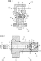
- the subsea housing assembly 100 includes a first housing portion 10 and a second housing portion 20.
- the first housing portion 10 includes a first housing body 12 and a first chamber 11.
- the second housing portion 20 includes a second housing body 22 and a second chamber 21.
- the first and second housing bodies 12, 22 include flanges 18, 28, respectively, by means of which they are fixedly attached to each other. In the present example, both housing portions are bolted together.
- the first housing body 12 substantially surrounds the first chamber 11.
- the first housing portion 10 includes a wall 30 that provides a pressure barrier. This allows application of a high pressure difference across the walls of the first housing body 12.
- the wall 30 provides separation between the first chamber 11 and the second chamber 21. Accordingly, a safe and reliable sealing can be provided between the first and second chambers 11, 21 that is capable of withstanding high pressure differences, for example in excess of 1,000 or even 2,000 bar.
- the first housing portion 10 may simply be closed, for example by means of a closing plate or the like.
- a closing plate or the like may be employed when the subsea housing assembly 100 is used for a subsea canister, such as a subsea electronic canister or a control canister or control module.
- the subsea housing assembly 100 is used for a subsea sensor 200 and a first pressure barrier 17 is provided in the first housing portion 10.
- the first pressure barrier 17 provides sealing of the first chamber 11 towards a part of the first housing portion 10 in which a sensor element 61 is located and exposed to high pressures, such as the high pressure of a process fluid.
- high pressures such as the high pressure of a process fluid.
- exposure may be a direct exposure, or an indirect exposure, for example via a respective process diaphragm and a pressure transmission fluid such as oil or the like.
- the first chamber 11 may comprise sensor electronics 62, such as control electronics, data processing electronics and the like.
- the first chamber 11 may be a pressure resistant chamber in which a predefined pressure is maintained, even when the subsea housing assembly 100 is installed at a subsea location.
- Such pressure may be a pressure below 10 bar and it may preferably be a pressure below 5 bar, or even below 1.5 bar.
- a close to atmospheric pressure may prevail in the first chamber 11, which may thus be termed an atmospheric chamber.
- Chamber 11 may be filled with a gas, such as nitrogen, or a gas mixture, such as air or a mixture of nitrogen with other gasses. It may thus be possible to operate conventional electric and electronic components within chamber 11.
- first pressure barrier 17 may for example comprise a feed through for an electric connection to the sensor element 61, or the sensor element 61 may itself be configured so as to constitute a pressure barrier. Under certain conditions, such pressure barrier may fail, thus allowing high pressure fluid to enter chamber 11.
- a prior art wall 30 must often be constructed such that it provides a second barrier so that the pressure can be confined effectively within the first housing portion 10.
- an inductive coupler 50 comprising a first coupling section 51 and a second coupling section 52 is provided.
- the inductive coupler and the wall section through which the coupling is effected are shown in Fig. 1 in terms of functional blocks only and will be explained in more detail below with reference to Figs. 4 and 5 .
- the first coupling section 51 is disposed in the first chamber 11 and connected to an electrical connection 15 that provides at least data communication, in particular with the sensor element 61 or the sensor electronics 62 in the example of Fig. 1 .
- the second coupling section 52 is disposed in the second chamber 21 and is connected to a second electrical connection 25 in the second housing portion 20.
- the inductive coupler 50 provides at least data communication between the first and second electrical connections 15, 25 across the wall 30. Besides transmitting data communications, the coupler 50 may also be configured to transfer power from the electrical connection 25 to the electrical connection 15.
- the first and second coupling sections 51, 52 are implemented as coils the arrangement of which will be shown below with reference to Figs. 4 and 5 .
- An alternating current (AC) provided to the second coupling section 52 may for example create a alternating magnetic field which in turn induces a current in the first coupling section 51 which then may be used to provide electric power to electric and electronic components comprised in the first housing portion 10 including sensor electronics 62 and sensor element 61.
- modulation may be provided.
- the current applied to the coil 52 may be modulated, and such modulation will lead to a modulation of the current induced in the first coupling section 51.
- a receiver/transmitter 56 may be provided in the second housing portion 20 and can be coupled to the second electrical connection 25.
- Unit 56 can include a receiver and a transmitter, and it may modulate control signals received on line 41 for transmission via the inductive coupler 50, and it may demodulate signals received from the second coupling section 52 for further transmission via the line 41.
- the transmitter/receiver 56 may also be located at a different position, for example at the other end of line 41, at a topside location or at a subsea data processing center.
- a transmitter/receiver 55 is provided in the first housing portion 10 in chamber 11 and is connected to the first electrical connection 15 and the first coupling section 51.
- Unit 55 may for example detect a modulation of a current received from the first coupling section 51 and may provide corresponding control signals to the sensor electronics 62.
- Unit 55 may further receive sensor data from the sensor electronics 62 and may modulate such sensor data onto a signal that is provided to the first coupling section 51, so that an alternative magnetic field is created which is coupled to second coupling section 52 and induces a current therein that is detected and demodulated by transmitter/receiver unit 56. Accordingly, data recorded by the sensor element 61 can be communicated on line 41 without requiring electric wires penetrating wall 30 which provides the secondary pressure barrier.
- inductive coupler 50 comprises one first coupling section and one second coupling section.
- inductive coupler 50 may comprise plural coupling sections, for example some dedicated to the transfer of electrical power and others dedicated to the transfer of data communications so as to provide multiple coupling paths to avoid signal degradation by magnetic interference of the inbound and the outbound signal and/or power transmission.
- the second chamber 21 can be a pressure compensated chamber the pressure of which is balanced to the surrounding ambient pressure, in particular the subsea pressure when the housing assembly 100 is installed subsea.
- the differential pressure across the walls of the second housing body 22 is accordingly relatively low.
- the housing body 22 has an opening in which the second coupling section 52 is located. This opening is sealed against the first housing body 12, for example by means of O-ring seals 29. Double seals are preferably provided.
- the second chamber 21 may be filled with a substantially incompressible medium, in particular a dielectric liquid or gel, such as oil or the like.
- a substantially incompressible medium in particular a dielectric liquid or gel, such as oil or the like.
- the electric and electronic components of unit 56 may be adapted to operate in such environment, or, as mentioned above, unit 56 may be located outside the chamber 21, for example in a subsea canister to which the sensor 200 is connected, or at a topside location. Pressure compensation may occur by means of a dedicated pressure compensator forming part of the subsea housing assembly 100 (not shown).
- the subsea housing assembly 100 may be connected to a subsea cable in the form of an oil filled hose, wherein the inner volume of such hose is filled with a dielectric liquid (in particular oil) and is pressure compensated against the ambient environment due to the flexibility of the hose.
- Pressure compensation of the second chamber 21 can occur via such hose, for example by allowing a flow communication through the opening 26 between the inner volume of the hose and the chamber 21, or by providing some pressure transmitting element in the opening, such as a membrane or bellows.
- the second chamber 21 may be a pressure resistant chamber.
- a predefined pressure below 10 bar, preferably below 5 bar or below 1.5 bar, such as close to atmospheric pressure may be maintained in chamber 21.
- a penetrator providing a pressure barrier can be provided in the opening 26. Since such penetrator has to withstand the differential pressure between the interior pressure of chamber 21 and the external subsea pressure when installed subsea, the pressure difference is relatively low compared to the pressure difference that can prevail when a barrier is exposed to the pressure of process fluid, such as the barrier provided by wall 30.
- the second housing portion 20 may for example comprise a fitting or connector for providing a connection to a subsea cable.
- a further unit such as a control module or the like, may be mounted directly to the subsea housing assembly 100.
- the insulation resistance would in such a case be measured between the metal cage provided by the first and second housing bodies 12, 22 and the respective coupling section 51, 52, so that insulation resistance can be kept high.
- the insulation resistance can also be maintained during high pressure testing.
- Fig. 2 illustrates a subsea housing assembly 100 wherein the inductive coupler comprises an outer and an inner coil wherein the outer coil at least partly surrounds the inner coil and wherein at least part of the wall extends between the inner coil and the outer coil as discussed in EP 3269921 .
- the inductive coupler comprises an outer and an inner coil wherein the outer coil at least partly surrounds the inner coil and wherein at least part of the wall extends between the inner coil and the outer coil as discussed in EP 3269921 .
- the first housing portion 10 is provided with a seal 19 for sealing against a subsea device, in particular a metal body, such as a pipe section.
- the seal 19 is preferably provided in form of a metal seal, in particular a metal gasket.
- the first coupling section 51 is provided in the form of an inner coil
- the second coupling section 52 is provided in the form of an outer coil that extends around the inner coil.
- the coils are arranged coaxially.
- the wall 30 extends between the first and second coupling sections 51, 52. Accordingly, in the example of Fig. 2 , the wall 30 is curved and extends around the inner coil. Wall 30 is formed integrally with the first housing body 12 of the first housing portion 10.
- the second housing body 22 has a smaller diameter portion that is attached to a larger diameter portion (flange 18) of the first housing body 12.
- the second housing body 22 may be screwed into the first housing body 12.
- seals 29 are provided, which can be in the form of elastomeric or metal O-ring seals.
- the opening 26 has the form of a fitting, into which the end of a subsea cable such as an oil filled hose can be screwed or otherwise be attached. As an example, it may be an MKII fitting.
- a mounting flange 16 is provided for mounting the subsea housing assembly 100 to the other subsea device, in particular pipe section.
- a subsea housing assembly 100 that is part of an embodiment of a subsea sensor 200 is illustrated.
- the subsea housing assembly 100 is mounted to a subsea pipe 80 through which a process fluid flows.
- the first housing body 12 is pressed against the subsea pipe 80 by means of the mounting flange 16 and sealed by means of the seal 19 which may for example be a metal gasket. Note that two seals 19 may be provided to provide a double barrier.
- Sensor element 61 may for example measure temperature and/or pressure of the process fluid flowing through the pipe section 80, and respective readings may be modulated and transmitted by the transmitter/receiver 55 via the inductive coupler 50, which again is shown in terms of functional blocks only and will be explained in more detail below with reference to Figs. 4 and 5 .
- a subsea cable in form of an oil filled hose 40 is mounted to the port opening 26 of the second housing portion 20 .
- the subsea cable may form part of the subsea sensor 200 and that a (wet mate or dry mate) connector may be provided at the other end of the subsea cable 40 for connecting the sensor 200 to another subsea device or to a topside installation.
- line 41 of subsea cable 40 is directly connected to electrical connection 25 and second coupling section 52.
- further electric and electronic components such as the transmitting/receiving unit 56 may be provided.
- the opening 26 may in some embodiments allow a flow communication between the interior of subsea cable 40 and the second chamber 21, while in other embodiments, separation may be provided.
- separation can be provided by a pressure transmitting element such as a membrane, or by means of a penetrator which allows the maintaining of a pressure difference across the opening 26.
- Figs. 4 shows an improvement to the inductive coupler discussed in EP 3269921 .
- a two-part flux guide 53A, 53B is provided to bidirectionally guide the magnetic flux between the coils 51, 52.
- the flux guide is made from a soft magnetic material such as a ferrite.
- Fig. 4 does not show the smallest possible arrangement comprising one first coil 51 arranged inside the first housing portion 10 and one second coil arranged inside the second housing portion 20.
- Fig. 4 shows an arrangement wherein two sets A, B of coils 51, 52 are provided for redundancy and/or to provide separate paths for coupling into and out of the first housing portion 10.
- the following discussion is independent on the number of coil sets which may of course exceed 2 as will be readily apparent to those with skills in the art.
- the flux guide 53 shown in Fig. 4 is made of soft magnetic material and comprises two parts: an inner body 53A arranged inside the first housing portion 10 and an outer body 53B arranged inside the second housing portion 20. Almost any shape of inner and outer body 53, alone and in combination, will improve the performance of the magnetic coupling 50 as long as such body is arranged near one of the coils 51, 52.
- both bodies are present and formed and arranged such that when assembled they form an overall body enclosing both coils in length and diameter.
- the outer body 53B is essentially a cylindrical cap or dome covering both the outer coil 52 and the wall section 30 extending between the coils 51, 52
- the inner body 53A is a cylindrical body, fully filling the inner coil 51 and the inside of the wall section 30, the inner body 53A further comprising a cylindrical base which at least has approximately the same diameter as the outer body's cylindrical cap or dome.
- the inner body may have an axial bore and/or be provided in the form of a hollow cylinder so as to reduce its weight and/or cost and/or to reduce the amount of magnetic field near the inner body's axis.
- Figs. 4 and 5 are schematic and the references to cylindrical or annular shapes herein are merely examples.
- the key design parameter is the thickness or strength of wall section 30 extending between the first and second coils, the selection of which is dictated by the overall design and purpose of the housing assembly.
- the wall section 30 by itself conventionally serves as a second barrier and needs to be able to withstand the pressure difference between the fluid to which the sensor is exposed and the sensor's environment. For testing purposes it needs to be able to reliably withstand at least 1.5 times that pressure difference, e.g. pressures of up to 1,500 or 2,100 bar or even 3,000 bar in typical subsea applications.
- the thickness or strength of wall section 30 extending between the first and second coils will be chosen first and depends on the maximum test pressure and the material chosen for wall 30.
- the wall thickness will be considerable in a subsea application the transmission loss will be high and needs to be taken into consideration for coupling power into the first housing portion 10: the power requirements of the circuitry inside first housing portion will be an important design criterion for the inductance and thus the dimensions of the coil and the dimensions of the flux guide.
- Fig. 5 An improvement to the arrangement shown in Fig. 4 is shown in Fig. 5 .
- the explanations given above with respect to Figs. 1, 2 , 3 and 4 are equally applicable to Fig. 5 , and only the differences and improvements are explained in more detail hereinafter.
- the thickness of the part of the wall extending between the coils is lower bounded by the mechanical requirements but in accordance with the present invention may be reduced below the lower bound by structurally supporting the part of the wall extending between the coils.
- the inductive coupler 50 comprises two coil sets denoted by suffixes A, B, respectively. As discussed above, in other embodiments there may only be one coil set and in yet other embodiments there may be more than two coils sets.
- the first coupling section 51A of the first coil set A is provided in the form of an inner coil
- the second coupling section 52A of the first coil set A is provided in the form of an outer coil that extends around the inner coil. Both coils are preferably arranged coaxially.
- a first coupling section 51B of the second coil set B is provided in the form of an inner coil
- the second coupling section 52B of the second coil set B is provided in the form of an outer coil that extends around the respective inner coil.
- a part of the wall 30 extends between the first and second coupling sections 51A, 52A, 51B, 52B. Accordingly, in the example of Fig. 5 , the wall 30 has a cylindrical or pot-shaped extension and extends around the inner coil or coils. Wall 30 and its extension are preferably formed integrally with the first housing body 12 of the first housing portion 10.
- a first flux guide arrangement 531A, 532A is arranged such that it facilitates the magnetic flux of the first coil system A and comprises an inner body 531A and an outer body 532A.
- both bodies are present and formed and arranged such that when assembled they form an overall body which, in conjunction with the section of the wall extending between the inner and outer coils, encloses both coils in length and diameter.
- both the inner and the outer body of the flux guide arrangement may be constructed from two identical half-bodies.
- the half-bodies forming the outer body 532A are essentially hollow cylinders with an inner diameter designed to accept the outer coil with as little air gap as possible between the outer circumference of the outer coil and the inner circumference of the half-body of the outer body.
- the outer half-body may have a cylindrical base having a smaller inner diameter chosen such that the half-body can be installed on the cylindrical extension of wall 30 with a small or no air gap.
- the outer diameter of the half-body is chosen such that an outer support structure 572 can be fitted over the outer body with a small or no air gap.
- the outer portion of the first coil set may then be assembled by first placing the first half-body of the outer body, base first, on the wall extension, then placing the outer coil on the wall extension and to about half of its length inside the first half-body, and then placing the second half-body of the outer body over the other half of the coil.
- the outer coil is, on the outside, completely encapsulated by the outer body 532A while resting on the wall extension on the inside.
- the inner half-bodies are essentially full cylinders having an outer diameter designed such that the inner coils can be installed on the half body.
- the inner half-body may have a cylindrical base having a larger outer diameter chosen such that the half-body can be installed inside the cylindrical extension of the wall with only a small or no air gap at the base.
- the inner portion of the coil set may then be assembled by first placing the first half-body of the inner body, base first, inside the wall extension, then placing the inner coil to about half of its length inside the first half-body, and then placing the second half-body of the inner body inside the wall extension and over the other half of the coil.
- the inner coil is, on the inside, completely encapsulated by the inner half-body while the inner coil's outside rests inside or against the wall extension.
- the outer half-bodies may also described as bodies that were obtained by rotating an "L” shape whereas the inner half-bodies may also be described as bodies that were obtained by rotating a "T” shape.
- the second, optional, coil set B is constructed and installed in a similar fashion as described with reference to the first coil set above.
- the construction of coil set B may be identical to that of coil set A thereby reducing the manufacturing cost by reducing the amount of individual parts. It is however not necessary construct both coil sets with the same dimensions.
- the longitudinal extensions of the coil sets A, B may be different, or the diameters of the coils and flux guide portions and the wall section may be different for the two coil systems, or the coil wiring may be different.
- the coils 51A, 51B, 52A, 52B are arranged concentrically or coaxially. More preferably the coils forming one coil set, for example coils 51A, 52A, and the respective flux guides 531A, 532A for the first coil set A, are (with respect to the extension of the wall 30) longitudinally aligned as shown in the cross-sectional view in Fig. 5 so as to maximize the symmetry thereby optimizing the magnetic field line paths emanating at the ends of the coils.
- the wall thickness of the cylindrical extension of wall 30 may be chosen to be less than the minimum value required to ensure its functioning as second pressure barrier. In embodiments of the present invention it may be sufficient to design the extension of wall 30 such that it acts as a fluid-tight barrier having a thickness of less than 10 mm, preferably 5 mm or less, while the structural stability of the wall section that extends between the coils is ensured by a support structure which in the preferred embodiment comprises an inner support structure 571 and an outer support structure 572.
- the inner support structure may be provided in the form of a full cylinder that fits inside the cylindrical wall extension and extends longitudinally so as to also support, or hold in place, the coil/flux body arrangement inside the cylindrical wall extension.
- the inner support structure 571 may comprise a cylindrical base having a larger diameter to increase its stability and to limit the amount of penetration into the cylindrical wall extension.
- the inner support may for example be a bolt that is held in place by form fit or friction fit or a combination thereof.
- the outer support structure 572 may be in the form of a cylindrical cap or dome fully enclosing the wall extension and the coil/flux body arrangement arranged on the outside of the wall extension.
- the outer support structure may comprise a cylindrical base or flanges for fixing the outer support structure to the first body section 12 and/or the wall 30.
- Inner support structure 571 may comprise one or more thin channels 581 wherein the wires to and from the inner coils 51A, 51B run.
- the outer support structure 572 may comprise one or more thin channels 582 wherein the wires to and from the outer coils 52A, 52B run. Additionally, these channels may be used to inject mold and release air to allow moldflow. These thin channels do not affect the mechanical stability of the inner support structure much. Although process fluid may enter the thin channel opening towards the first chamber 11 if the first barrier breaks the force exerted by the process fluid inside the thin channel (having a small cross-sectional area) will be small and thus the channels can be reliably sealed by relatively thin end walls (not shown).
- either or both channels 581, 582 may be filled with a mold so as to prevent the process fluid from entering if the first barrier breaks.
- any gaps and/or openings that remain within the inductive coupler 50 to facilitate the manufacturing process and/or to facilitate different thermal expansion behaviors of the different components may be filled with a mold, preferably an elastic mold, at the end of the assembly process.
- FIGs. 4 and 5 are schematic and the references to cylindrical or annular shapes herein are merely examples. It will be readily apparent to those with skills in the art how to adapt the shapes discussed herein to accommodate such other shapes.
- the section of the wall 30 extending between the first and second coils preferably extends or protrudes into the second chamber 21 enough to allow a complete overlap between the coils 51, 52, including all coils if there are several as in the embodiment of Fig. 5 , and more preferably it extends into the second chamber enough so as to allow, for all coil sets, the alignment described above.
- support discs 591, 592, 593 may be installed.
- a support disc arrangement 591, 592 may be installed between the two coil sets A, B such that an inner support disc 591 is arranged between the inner flux guide body 531A of the first coil arrangement and the inner flux guide body 531B of the second coil arrangement.
- An outer support disc 592 is arranged between the outer flux guide body 532A of the first coil arrangement and the outer flux guide body 532B of the second coil arrangement.
- the discs 591, 592 are preferably concentric and longitudinally aligned along the wall extension.
- the inner support disc 591 is preferably fitted inside the cylindrical wall extension with little or no air gap.
- outer support disc 592 is preferably fitted onto the cylindrical wall extension with little or no air gap and inside the outer support structure 572 with little or no air gap.
- the disc arrangement 591, 592 may be designed to couple expansion forces from the inside of the wall extension to the outer support structure, and it may further be designed to exert predefined compression forces from the outer support structure to the wall extension wherein the inner support disc 591 absorbs these forces in order to avoid deformation of the wall extension.
- At least one set of support discs 591, 592 are arranged between the coil systems A and B and are preferably made of a material that also acts as an electromagnetic shield so as to dampen the cross-coupling between the coil systems.
- electromagnetic shielding structures may be provided between the coil systems A and B, for example in the form of discs 591, 592 which additionally provide a mechanical support.
- a third disc 593 is shown to be installed at the outer end of the cylindrical wall extension to provide a coupling fit between the wall extension and the outer support structure.
- the outer support structure may simply comprise a section with a reduced inner diameter for accommodating the cylindrical wall extension (i.e. have an integrated disc).
- the support discs 591, 592, 593 may have small through holes so that the thin channels 581, 582 may extend beyond the support discs.
- the wall section extending between the inner coil and the outer coil extends from the first chamber 11 wherein electric and/or electronic components associated with the sensing element are disposed into the second chamber 21 wherein electric and/or electronic components associated with the signal processing and/or onward signal propagation are disposed.
- the wall section 30 extending between the inner coil and the outer coil may in other embodiments extend from the second chamber 21 into the first chamber 11.
- Providing two sets of coils as shown in Figs. 4 and 5 provides a variety of design choices. For example distinct paths (and adapted coil sets) may be provided for transmitting power and/or control data into the first chamber and/or for transmitting sensor data out of the first chamber.
- the second coil set may be provided as a redundancy measure, noting that subsea sensors typically need to be designed for extremely long lifetimes, e.g. in excess of 20 or 30 years.
- the coil sets are shown to be arranged next to each other.
- the coil sets may also be arranged around/inside each other or the respective coils of the coil sets may be created by winding a double wire around the same core wherein one wire serves as one of the respective coils and the other wire serves as the other coil.
- the interference between the coil sets is very high and these configurations are thus preferable if the redundancy concept is of the fail-over type such that one coil set is kept inactive until the active coil set fails.
- Stacking the separate coil systems in a longitudinal direction as shown in Fig. 5 has the advantage that the interference of the respective alternating magnetic fields can be kept low and will be lower compared to that of a design in accordance with Fig. 4 because each coil set has a separate flux guide. Still, each of the coil systems will couple its signals to some extent into the other (cross coupling), in particular if the part of the wall extending between the coils is made thinner. This may be used advantageously to create a second received signal, for example to increase the yield in transmitted power or to improve signal transmission. If such is not desired the cross coupling can be suppressed by using different resonance and driving frequencies for the two coil systems.
- the subsea housing assembly 100 is described above with respect to the use in a subsea sensor 200, yet it is to be understood that it may also be used in other applications, in particular where the integrity of a pressure barrier is of importance, for example for protecting electric and electronic components.
- Such applications may include the application in a subsea control unit where the integrity of a one atmospheric chamber needs to be ensured.
- Other applications are equally conceivable.
Landscapes
- Physics & Mathematics (AREA)
- Life Sciences & Earth Sciences (AREA)
- Engineering & Computer Science (AREA)
- Geology (AREA)
- Mining & Mineral Resources (AREA)
- General Physics & Mathematics (AREA)
- Environmental & Geological Engineering (AREA)
- Fluid Mechanics (AREA)
- General Life Sciences & Earth Sciences (AREA)
- Geochemistry & Mineralogy (AREA)
- Measuring Fluid Pressure (AREA)
- Arrangements For Transmission Of Measured Signals (AREA)
Priority Applications (7)
| Application Number | Priority Date | Filing Date | Title |
|---|---|---|---|
| EP18151877.0A EP3511516A1 (de) | 2018-01-16 | 2018-01-16 | Unterwassergehäuseanordnung |
| BR112020014333-2A BR112020014333B1 (pt) | 2018-01-16 | 2018-12-06 | Montagem de alojamento submarino e sensor submarino |
| PCT/EP2018/083852 WO2019141432A1 (en) | 2018-01-16 | 2018-12-06 | Subsea housing assembly |
| EP18829751.9A EP3740647B1 (de) | 2018-01-16 | 2018-12-06 | Unterwassergehäuseanordnung |
| AU2018403485A AU2018403485B2 (en) | 2018-01-16 | 2018-12-06 | Subsea housing assembly |
| US16/961,670 US11460367B2 (en) | 2018-01-16 | 2018-12-06 | Subsea housing assembly |
| CN201890001470.1U CN214118142U (zh) | 2018-01-16 | 2018-12-06 | 海底壳体组件和海底传感器 |
Applications Claiming Priority (1)
| Application Number | Priority Date | Filing Date | Title |
|---|---|---|---|
| EP18151877.0A EP3511516A1 (de) | 2018-01-16 | 2018-01-16 | Unterwassergehäuseanordnung |
Publications (1)
| Publication Number | Publication Date |
|---|---|
| EP3511516A1 true EP3511516A1 (de) | 2019-07-17 |
Family
ID=60997369
Family Applications (2)
| Application Number | Title | Priority Date | Filing Date |
|---|---|---|---|
| EP18151877.0A Withdrawn EP3511516A1 (de) | 2018-01-16 | 2018-01-16 | Unterwassergehäuseanordnung |
| EP18829751.9A Active EP3740647B1 (de) | 2018-01-16 | 2018-12-06 | Unterwassergehäuseanordnung |
Family Applications After (1)
| Application Number | Title | Priority Date | Filing Date |
|---|---|---|---|
| EP18829751.9A Active EP3740647B1 (de) | 2018-01-16 | 2018-12-06 | Unterwassergehäuseanordnung |
Country Status (6)
| Country | Link |
|---|---|
| US (1) | US11460367B2 (de) |
| EP (2) | EP3511516A1 (de) |
| CN (1) | CN214118142U (de) |
| AU (1) | AU2018403485B2 (de) |
| BR (1) | BR112020014333B1 (de) |
| WO (1) | WO2019141432A1 (de) |
Cited By (2)
| Publication number | Priority date | Publication date | Assignee | Title |
|---|---|---|---|---|
| US11066889B2 (en) | 2018-03-13 | 2021-07-20 | Siemens Energy AS | Subsea assembly |
| EP3957965A1 (de) * | 2020-08-11 | 2022-02-23 | WOCO Industrietechnik GmbH | Kabellose fluidtemperaturerfassung eines mehrwegeventils |
Families Citing this family (1)
| Publication number | Priority date | Publication date | Assignee | Title |
|---|---|---|---|---|
| GB202007828D0 (en) | 2020-05-26 | 2020-07-08 | Siemens Energy AS | Electrical coupling |
Citations (5)
| Publication number | Priority date | Publication date | Assignee | Title |
|---|---|---|---|---|
| US5052941A (en) * | 1988-12-13 | 1991-10-01 | Schlumberger Technology Corporation | Inductive-coupling connector for a well head equipment |
| WO2014123425A1 (en) * | 2013-02-06 | 2014-08-14 | Aker Subsea As | Subsea valve |
| WO2015139953A1 (en) * | 2014-03-19 | 2015-09-24 | Siemens Aktiengesellschaft | Power switching device |
| US20160024869A1 (en) * | 2014-07-24 | 2016-01-28 | Conocophillips Company | Completion with subsea feedthrough |
| EP3269921A1 (de) | 2016-07-14 | 2018-01-17 | Siemens Aktiengesellschaft | Unterwassergehäuseanordnung |
Family Cites Families (6)
| Publication number | Priority date | Publication date | Assignee | Title |
|---|---|---|---|---|
| US8056619B2 (en) * | 2006-03-30 | 2011-11-15 | Schlumberger Technology Corporation | Aligning inductive couplers in a well |
| WO2009150054A1 (de) * | 2008-05-28 | 2009-12-17 | Koenig & Bauer Aktiengesellschaft | Rollenoffsetdruckmaschine sowie verfahren zum betrieb der rollenoffsetdruckmaschine |
| CA2795818C (en) * | 2011-11-16 | 2015-03-17 | Weatherford/Lamb, Inc. | Managed pressure cementing |
| US9430881B2 (en) * | 2013-03-15 | 2016-08-30 | Broadley-James Corporation | Measurement probe with heat cycle event counter |
| US10323468B2 (en) * | 2014-06-05 | 2019-06-18 | Schlumberger Technology Corporation | Well integrity monitoring system with wireless coupler |
| EP3767967B1 (de) * | 2019-07-15 | 2023-08-23 | Nokia Technologies Oy | Fernmessung |
-
2018
- 2018-01-16 EP EP18151877.0A patent/EP3511516A1/de not_active Withdrawn
- 2018-12-06 BR BR112020014333-2A patent/BR112020014333B1/pt active IP Right Grant
- 2018-12-06 WO PCT/EP2018/083852 patent/WO2019141432A1/en unknown
- 2018-12-06 AU AU2018403485A patent/AU2018403485B2/en active Active
- 2018-12-06 US US16/961,670 patent/US11460367B2/en active Active
- 2018-12-06 EP EP18829751.9A patent/EP3740647B1/de active Active
- 2018-12-06 CN CN201890001470.1U patent/CN214118142U/zh active Active
Patent Citations (5)
| Publication number | Priority date | Publication date | Assignee | Title |
|---|---|---|---|---|
| US5052941A (en) * | 1988-12-13 | 1991-10-01 | Schlumberger Technology Corporation | Inductive-coupling connector for a well head equipment |
| WO2014123425A1 (en) * | 2013-02-06 | 2014-08-14 | Aker Subsea As | Subsea valve |
| WO2015139953A1 (en) * | 2014-03-19 | 2015-09-24 | Siemens Aktiengesellschaft | Power switching device |
| US20160024869A1 (en) * | 2014-07-24 | 2016-01-28 | Conocophillips Company | Completion with subsea feedthrough |
| EP3269921A1 (de) | 2016-07-14 | 2018-01-17 | Siemens Aktiengesellschaft | Unterwassergehäuseanordnung |
Cited By (2)
| Publication number | Priority date | Publication date | Assignee | Title |
|---|---|---|---|---|
| US11066889B2 (en) | 2018-03-13 | 2021-07-20 | Siemens Energy AS | Subsea assembly |
| EP3957965A1 (de) * | 2020-08-11 | 2022-02-23 | WOCO Industrietechnik GmbH | Kabellose fluidtemperaturerfassung eines mehrwegeventils |
Also Published As
| Publication number | Publication date |
|---|---|
| EP3740647B1 (de) | 2023-01-25 |
| WO2019141432A1 (en) | 2019-07-25 |
| AU2018403485A1 (en) | 2020-06-25 |
| BR112020014333B1 (pt) | 2023-10-24 |
| CN214118142U (zh) | 2021-09-03 |
| BR112020014333A2 (pt) | 2020-12-08 |
| AU2018403485B2 (en) | 2021-04-01 |
| EP3740647A1 (de) | 2020-11-25 |
| US20200400522A1 (en) | 2020-12-24 |
| US11460367B2 (en) | 2022-10-04 |
Similar Documents
| Publication | Publication Date | Title |
|---|---|---|
| US11656106B2 (en) | Subsea housing assembly | |
| US11460367B2 (en) | Subsea housing assembly | |
| EP3511519B1 (de) | Unterwassergehäuseanordnung | |
| EP3511517B1 (de) | Unterwassergehäuseanordnung | |
| RU2398333C2 (ru) | Герметичный для текучей среды ввод проводов | |
| EP2031288B1 (de) | Durchführung und buchse | |
| CN107851467B (zh) | 用于核反应堆容器的电气贯穿组件 | |
| CN109540188B (zh) | 双隔间环境密封件 | |
| US11746604B2 (en) | Subsea housing assembly and subsea sensor | |
| CN104931194B (zh) | 用于测量燃烧涡轮燃烧器中的压力波动的探测器 | |
| BR112020013499B1 (pt) | Montagem de alojamento submarino e sensor submarino | |
| US11506046B2 (en) | Instrumented coupling electronics | |
| CN213022107U (zh) | 一种防水防腐蚀的气象气压传感装置 | |
| CN210893269U (zh) | 一种矿用隔爆兼本安型流量计 | |
| US20030056603A1 (en) | Differential pressure transmitter with simplified structure | |
| KR20180022372A (ko) | 제네레이터 밀폐 시스템 |
Legal Events
| Date | Code | Title | Description |
|---|---|---|---|
| PUAI | Public reference made under article 153(3) epc to a published international application that has entered the european phase |
Free format text: ORIGINAL CODE: 0009012 |
|
| AK | Designated contracting states |
Kind code of ref document: A1 Designated state(s): AL AT BE BG CH CY CZ DE DK EE ES FI FR GB GR HR HU IE IS IT LI LT LU LV MC MK MT NL NO PL PT RO RS SE SI SK SM TR |
|
| AX | Request for extension of the european patent |
Extension state: BA ME |
|
| STAA | Information on the status of an ep patent application or granted ep patent |
Free format text: STATUS: THE APPLICATION IS DEEMED TO BE WITHDRAWN |
|
| 18D | Application deemed to be withdrawn |
Effective date: 20200118 |