EP3511273B1 - De-stacking device for shells - Google Patents
De-stacking device for shells Download PDFInfo
- Publication number
- EP3511273B1 EP3511273B1 EP19150545.2A EP19150545A EP3511273B1 EP 3511273 B1 EP3511273 B1 EP 3511273B1 EP 19150545 A EP19150545 A EP 19150545A EP 3511273 B1 EP3511273 B1 EP 3511273B1
- Authority
- EP
- European Patent Office
- Prior art keywords
- insertion element
- tray
- rotation
- destacking
- gap
- Prior art date
- Legal status (The legal status is an assumption and is not a legal conclusion. Google has not performed a legal analysis and makes no representation as to the accuracy of the status listed.)
- Active
Links
- 238000000034 method Methods 0.000 claims description 13
- 238000003780 insertion Methods 0.000 claims 26
- 230000037431 insertion Effects 0.000 claims 26
- 230000001174 ascending effect Effects 0.000 claims 2
- 238000007654 immersion Methods 0.000 description 26
- 238000007789 sealing Methods 0.000 description 5
- 238000011161 development Methods 0.000 description 1
- 230000018109 developmental process Effects 0.000 description 1
- 235000012054 meals Nutrition 0.000 description 1
- 230000000284 resting effect Effects 0.000 description 1
- 230000002441 reversible effect Effects 0.000 description 1
Images

Classifications
-
- B—PERFORMING OPERATIONS; TRANSPORTING
- B65—CONVEYING; PACKING; STORING; HANDLING THIN OR FILAMENTARY MATERIAL
- B65G—TRANSPORT OR STORAGE DEVICES, e.g. CONVEYORS FOR LOADING OR TIPPING, SHOP CONVEYOR SYSTEMS OR PNEUMATIC TUBE CONVEYORS
- B65G59/00—De-stacking of articles
- B65G59/10—De-stacking nested articles
- B65G59/107—De-stacking nested articles by means of rotary devices or endless elements
- B65G59/108—De-stacking nested articles by means of rotary devices or endless elements the axis of rotation being substantially parallel to the axis of the stack
Definitions
- the invention relates to a stacking device according to claim 1 and to a method for operating such a stacking device.
- a destacking device with special destacking elements for destacking the above-mentioned trays is available from WO 2016/169566 A1 known. These destacking elements do not rotate endlessly, but turn 90° to 180° in a first direction and back again, i.e. reversing, to unstack one tray at a time. These destacking elements have a spring-loaded support element and a spring-loaded separating element, with a gap provided between the support element and the separating element in the direction of the axis of rotation of the destacking element.
- the bottommost tray rests on the support element with its downwardly angled edge, and as the destacking element rotates, the separating element presses sideways onto the angled edge of the bottommost tray.
- the angled edge of the tray dips into the gap, and as the rotation continues, the support element ends and the bottommost tray can fall downwards.
- the separating element dips radially in the direction of the support of the tray edge and holds the next tray.
- the object of the invention is to provide a destacking device for continuous operation by means of destacking screws in order to destack the above-mentioned tray stacks.
- the invention relates to a stacking device comprising a frame for receiving at least one stack of trays and comprising a plurality of destacker screws which are configured to be operated continuously in one direction of rotation, each destacker screw having a separating disk and a helical spiral.
- the invention is characterized in that the separating disk has a first immersion element and a second immersion element, the first immersion element being configured to immerse itself in a gap between two adjacent trays when the destacker screw rotates in order to move these two adjacent trays a greater distance apart, and the second immersion element being configured to immerse itself in the gap created by the first immersion element.
- both immersion elements are provided as one piece on the separating disk in order to avoid having to provide any adjustment options for the two immersion elements relative to one another.
- a method according to the invention for operating in particular a previously described destacking device provides that the destacking screw, during its rotation, dips with the first immersion element into the gap between the lower tray, i.e. the tray to be destacked, and the tray above it, until the upper tray has been raised so far that a larger gap is created between the top of the tray edge of the lower tray and the tray edge of the tray above it, before the second immersion element dips into this gap at least partially over the top of the tray edge.
- a method with high process reliability can be provided in order to be able to destack, for example, meal trays with low stability, with a large overlap in the tray stack and with a very small distance between the outer tray edges, for example less than 3 mm.
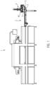
- Figure 1 shows a tray sealing machine 1 with a transport device 2, by means of which trays 3 are picked up by a destacking device 4 and transported to the tray sealing machine 1.
- the trays 3 are filled with products manually or automatically along the transport device 2.
- the destacking device 4 comprises a frame 40 and several destacking screws 5.
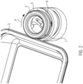
- Figure 2 shows an isometric view of a section of the stacking device 4 with trays 3 and a destacker screw 5.
- the destacker screw 5 has a separating disk 6 with a first immersion element 7 and a second immersion element 8. To destack individual trays 3, the destacker screw 5 shown rotates clockwise in the direction of rotation R.
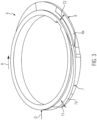
- FIG 3 shows the cutting disc 6 in an enlarged individual view.
- the first immersion element 7 has an upward slope in relation to its upper side 7a, against the direction of rotation R.
- the first immersion element 7 has an increase in diameter compared to the outer diameter D of a vertical wall of the cutting disc 6, which corresponds to a first immersion depth T1.
- T1 can reach a maximum value of e.g. 1.5 mm to 3.5 mm.
- the second immersion element 8 begins with its upper side 8a slightly below the upper side 7a of the first immersion element 7.
- the upper side 8a also has an upward slope in relation to the direction of rotation R.
- the second immersion element 8 has an increase in diameter compared to the outer diameter D, which corresponds to a second immersion depth T2, which can reach a value of e.g. 4 to 7.5 mm.
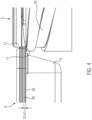
- the function of the two immersion elements 7, 8 is explained in the following. Figures 4 to 9 described in more detail.
- Figure 4 shows a tray stack 9 consisting of five trays 3, for example.
- a first tray 3a is stacked downwards individually is to be removed, the first tray 3a and thus the tray stack 9 rests on a support 11 of a helix 10 of the destacker screw 5.
- the second tray 3b located above the first tray 3a has a gap 13 with a first distance A1 of, for example, 2 mm between the two tray edges 12.
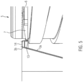
- Figure 5 shows an enlarged view with the first bowl 3a and the second bowl 3b. It shows a rotated position of the destacker screw 5, in which the separating disk 6 with its first immersion element 7 dips into the gap 13 between the bowl edges 12 of the first bowl 3a and second bowl 3b. 14 designates the sealing surface on which a lid film will later be sealed to the bowl 3.
- the first bowl 3a is meanwhile conveyed further downwards by means of the spiral 10.
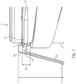
- the distance A1 of the gap has increased further to, for example, 9 mm, since the first shell 3a is moved further downwards while the second shell 3b simultaneously rests on the second immersion element 8.
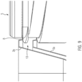
- Figure 9 shows a further rotation of the destacker screw 5, during which the second tray 3b and with it the tray stack 9 (not shown in detail) is moved along a downwardly directed slope of the second immersion element 8 to an upper starting level, so that in the subsequent work cycle the first immersion element 7 can again immerse itself in the gap 13 of the second tray 3b and the next tray 3 above it (see Fig.4 ).
Description
Die Erfindung bezieht sich auf eine Abstapelvorrichtung gemäß Anspruch 1 sowie auf ein Verfahren zum Betrieb einer solchen Abstapelvorrichtung.The invention relates to a stacking device according to claim 1 and to a method for operating such a stacking device.
Gattungsgemäße Abstapelvorrichtungen sind aus der
Eine Abstapelvorrichtung mit speziellen Entstaplerelementen zum Abstapeln von oben genannten Schalen ist aus der
Aufgabe der Erfindung ist es, eine Abstapelvorrichtung zum kontinuierlichen Betrieb mittels Entstaplerschrauben zur Verfügung zu stellen, um obengenannte Schalenstapel zu entstapeln.The object of the invention is to provide a destacking device for continuous operation by means of destacking screws in order to destack the above-mentioned tray stacks.
Diese Aufgabe wird gelöst durch eine Abstapelvorrichtung mit den Merkmalen des Anspruchs 1 oder durch ein Verfahren gemäß Anspruch 6. Vorteilhafte Weiterbildungen der Erfindung sind in den Unteransprüchen angegeben.This object is achieved by a stacking device having the features of claim 1 or by a method according to claim 6. Advantageous developments of the invention are specified in the subclaims.
Die Erfindung bezieht sich auf eine Abstapelvorrichtung, umfassend ein Gestell zum Aufnehmen wenigstens eines Schalenstapels und umfassend mehrere Entstaplerschrauben, die dazu konfiguriert sind, kontinuierlich in jeweils einer Drehrichtung betrieben zu werden, wobei jede Entstaplerschraube eine Trennscheibe und eine helixförmig ausgebildete Wendel aufweist. Die Erfindung zeichnet sich dadurch aus, dass die Trennscheibe ein erstes Eintauchelement und ein zweites Eintauchelement aufweist, wobei das erste Eintauchelement dazu konfiguriert ist, bei Rotation der Entstaplerschraube in eine Lücke von zwei benachbarten Schalen einzutauchen, um diese zwei benachbarten Schalen auf einen größeren Abstand auseinander zu bewegen, und wobei das zweite Eintauchelement dazu konfiguriert ist, in die mittels des ersten Eintauchelements erzeugte Lücke einzutauchen. So können auch Schalen entstapelt werden, die sich sehr weit überlappen und nur eine sehr kleine Lücke an den abgewinkelten äußeren Schalenrändern haben. Bevorzugt sind dabei beide Eintauchelemente einteilig an der Trennscheibe vorgesehen, um keine Einstellmöglichkeiten der zwei Eintauchelemente zueinander vorsehen zu müssen.The invention relates to a stacking device comprising a frame for receiving at least one stack of trays and comprising a plurality of destacker screws which are configured to be operated continuously in one direction of rotation, each destacker screw having a separating disk and a helical spiral. The invention is characterized in that the separating disk has a first immersion element and a second immersion element, the first immersion element being configured to immerse itself in a gap between two adjacent trays when the destacker screw rotates in order to move these two adjacent trays a greater distance apart, and the second immersion element being configured to immerse itself in the gap created by the first immersion element. This means that trays can also be destacked which overlap very widely and have only a very small gap at the angled outer tray edges. Preferably, both immersion elements are provided as one piece on the separating disk in order to avoid having to provide any adjustment options for the two immersion elements relative to one another.
Ein erfindungsgemäßes Verfahren zum Betrieb insbesondere einer zuvor beschriebenen Abstapelvorrichtung sieht vor, dass die Entstaplerschraube während ihrer Drehung mit dem ersten Eintauchelement in die Lücke zwischen unteren, also zu entstapelnden Schale und der darüber befindlichen Schale eintaucht, bis die obere Schale soweit angehoben wurde, dass zwischen der Oberseite des Schalenrands der unteren Schale und dem Schalenrand der darüber befindlichen Schale eine größere Lücke entsteht, bevor das zweite Eintauchelement in diese Lücke wenigstens teilweise über die Oberseite des Schalenrands eintaucht. So kann ein Verfahren mit hoher Prozesssicherheit bereitgestellt werden, um beispielsweise Menüschalen mit einer geringen Stabilität, mit einer großen Überlappung im Schalenstapel und mit einem sehr geringen Abstand zwischen den äußeren Schalenrändern, beispielsweise kleiner als 3 mm, entstapeln zu können.A method according to the invention for operating in particular a previously described destacking device provides that the destacking screw, during its rotation, dips with the first immersion element into the gap between the lower tray, i.e. the tray to be destacked, and the tray above it, until the upper tray has been raised so far that a larger gap is created between the top of the tray edge of the lower tray and the tray edge of the tray above it, before the second immersion element dips into this gap at least partially over the top of the tray edge. In this way, a method with high process reliability can be provided in order to be able to destack, for example, meal trays with low stability, with a large overlap in the tray stack and with a very small distance between the outer tray edges, for example less than 3 mm.
Im Folgenden wird die Erfindung anhand von Ausführungsbeispielen näher erläuert. Im Einzelnen zeigen:
- Fig. 1
- eine Schalenverschließmaschine mit einer Abstapelvorrichtung,
- Fig. 2
- eine isometrische Ansicht eines Ausschnitts der Abstapelvorrichtung mit Entstaplerschraube und Schale,
- Fig. 3
- eine Detailansicht einer Trennscheibe,
- Fig. 4
- eine seitliche Ansicht mit Schalenstapel und Entstaplerschraube in einer ersten Stellung der Entstaplerschraube und
- Fig. 5 bis 9
- weitere Stellungen der Entstaplerschraube in der Ansicht von
Fig. 4 .
- Fig.1
- a tray sealing machine with a stacking device,
- Fig.2
- an isometric view of a section of the destacking device with destacking screw and tray,
- Fig.3
- a detailed view of a cutting disc,
- Fig.4
- a side view with tray stack and destacker screw in a first position of the destacker screw and
- Fig. 5 to 9
- Further positions of the destacker screw in the view of
Fig.4 .
Gleiche Komponenten sind in den Figuren durchgängig mit gleichen Bezugszeichen versehen.Identical components are provided with the same reference numerals throughout the figures.
In
In
Claims (9)
- A destacker (4) comprising a rack (40) for accommodating at least one stack of trays (9) and further comprising a plurality of destacking screws (5) configured to be operated continuously in a respective direction of rotation (R), each destacking screw (5) having a separating disk (6) and a helically configured spiral (10), wherein the separating disk (6) comprises a first insertion element (7) and a second insertion element (8), the first insertion element (7) being configured to enter a gap (13) between two neighboring trays (3) during rotation of the destacking screw (5) so as to increase a distance (A1) between two neighboring trays (3) by at least 2 mm, and the second insertion element (8) being configured to enter the gap (13) that has been enlarged by means of the first insertion element (7),
wherein the first insertion element (7) has an upper side (7a) ascending in a direction opposite to the direction of rotation (R) of the destacking screw (5), and wherein an upper side (8a) of the second insertion element (8) has an upward slope in a direction opposite to the direction of rotation (R) of the destacking screw (5). - The destacker according to claim 1, characterized in that both insertion elements (7, 8) are provided on the separating disk (6) such that they are integral therewith.
- The destacker according to one of the preceding claims, characterized in that the second insertion element (8) horizontally projects farther from a vertical wall of the separating disk (6) than the first insertion element (7).
- The destacker according to one of the preceding claims, characterized in that the first insertion element (7) has a first insertion depth (T1) of 1.5 mm to 3.5 mm and/or that the second insertion element (8) has a second insertion depth (T2) of 4 mm to 7.5 mm.
- The destacker according to one of the preceding claims, characterized in that the upper side (8a) of the second insertion element (8) begins slightly below an upper end of the upper side (7a) of the first insertion element (7).
- Method for operating a destacker (4) for trays (3), wherein the destacker (4) comprises a rack (40) for accommodating at least one stack of trays (9) and a plurality of destacking screws (5), each destacking screw (5) having a separating disk (6) and a helically configured spiral (10), wherein the separating disk (6) comprises a first insertion element (7) and a second insertion element (8), andwherein the method comprises continuously rotating the destacking screws (5) in a direction of rotation (R), respectively, wherein the first insertion element (7) has an upper side (7a) ascending in a direction opposite to the direction of rotation (R) of the destacking screw (5), and wherein an upper side (8a) of the second insertion element (8) has an upward slope in a direction opposite to the direction of rotation (R) of the destacking screw (5), andwherein the method comprises the following method steps:- immersing of the destacking screw (5) during its rotation in the direction of rotation (R) with its first insertion element (7) into a gap (13) between a lowermost tray (3) to be destacked and a tray (3b) located above the lowermost tray,- lifting the tray (3b) located above the lowermost tray with an upper side (7a) of the first insertion element (7) upon further rotation of the destacking screw (5),- enlarging the gap (13) by lifting the tray (3b) located above the tray (3a) to be destacked,- immersing of the second insertion element (8) into the enlarged gap (13) between the tray (3a) to be destacked and the tray (3b) located above the tray to be destacked,- lowering the tray (3a) to be destacked on the helically configured spiral (10), while the tray (3b) located above the tray to be destacked remains held on the second insertion element (8).
- Method according to claim 6, characterized in that the vertical dimension (A1) of the gap (13) is increased by at least 50% or at least 100% starting from an initial value.
- Method according to claim 6 or 7, characterized in that the vertical dimension (A1) of the gap (13) is increased to 7 to 14 mm from an initial value in the region of 1,5 to 3 mm.
- Method according to any one of claims 6 to 8, characterized in that the second insertion element (8) immerses into the gap (13) along a horizontal direction further than the first insertion element (7).
Applications Claiming Priority (1)
| Application Number | Priority Date | Filing Date | Title |
|---|---|---|---|
| DE102018100498.2A DE102018100498A1 (en) | 2018-01-11 | 2018-01-11 | STACKING DEVICE FOR BOWLS |
Publications (2)
| Publication Number | Publication Date |
|---|---|
| EP3511273A1 EP3511273A1 (en) | 2019-07-17 |
| EP3511273B1 true EP3511273B1 (en) | 2024-04-17 |
Family
ID=65011859
Family Applications (1)
| Application Number | Title | Priority Date | Filing Date |
|---|---|---|---|
| EP19150545.2A Active EP3511273B1 (en) | 2018-01-11 | 2019-01-07 | De-stacking device for shells |
Country Status (4)
| Country | Link |
|---|---|
| EP (1) | EP3511273B1 (en) |
| CN (1) | CN209635436U (en) |
| DE (1) | DE102018100498A1 (en) |
| DK (1) | DK3511273T3 (en) |
Families Citing this family (4)
| Publication number | Priority date | Publication date | Assignee | Title |
|---|---|---|---|---|
| PL3573911T3 (en) * | 2017-01-25 | 2023-09-25 | Qupaq Aps | Destacker wheel |
| CN112938504A (en) * | 2019-11-26 | 2021-06-11 | 苏福生 | Automatic separator for stacked containers |
| DE102020113526B4 (en) | 2020-05-19 | 2022-09-01 | Vemag Maschinenbau Gmbh | Device and method for separating trays from a stack of several trays |
| CN113716356A (en) * | 2021-07-02 | 2021-11-30 | 上海侬盛现代农业科技有限公司 | Spiral basin falling mechanism |
Family Cites Families (8)
| Publication number | Priority date | Publication date | Assignee | Title |
|---|---|---|---|---|
| US4048915A (en) | 1976-04-07 | 1977-09-20 | Condes Corporation | Method and apparatus for denesting cartons |
| JPH01158410U (en) * | 1988-04-25 | 1989-11-01 | ||
| WO2011001451A1 (en) * | 2009-07-02 | 2011-01-06 | Vijay Chauhan | Method and appratus for grouping discrete laminar articles into bathes of predetermined count |
| DK177779B1 (en) * | 2013-08-28 | 2014-06-30 | Intech Internat A S | Dispensing apparatus and use |
| DK178264B1 (en) * | 2014-09-04 | 2015-10-19 | Intech Internat A S | Dispensing apparatus and use |
| WO2016169566A1 (en) | 2015-04-23 | 2016-10-27 | Jysk Konstruktionsteknik A/S | Denesting element for closely stacked objects |
| DK3246277T3 (en) | 2016-05-18 | 2021-04-19 | Multivac Haggenmueller Kg | Unstacking device for trays |
| PL3573911T3 (en) * | 2017-01-25 | 2023-09-25 | Qupaq Aps | Destacker wheel |
-
2018
- 2018-01-11 DE DE102018100498.2A patent/DE102018100498A1/en active Pending
-
2019
- 2019-01-07 DK DK19150545.2T patent/DK3511273T3/en active
- 2019-01-07 EP EP19150545.2A patent/EP3511273B1/en active Active
- 2019-01-10 CN CN201920040657.9U patent/CN209635436U/en active Active
Also Published As
| Publication number | Publication date |
|---|---|
| DE102018100498A1 (en) | 2019-07-11 |
| CN209635436U (en) | 2019-11-15 |
| DK3511273T3 (en) | 2024-04-29 |
| EP3511273A1 (en) | 2019-07-17 |
Similar Documents
| Publication | Publication Date | Title |
|---|---|---|
| EP3511273B1 (en) | De-stacking device for shells | |
| DE3244292C2 (en) | Coin transfer device | |
| DE3913437C2 (en) | Coin sorter | |
| DE2934954C2 (en) | Separating device | |
| EP3246277B1 (en) | Stacking device for shells | |
| EP3363752B1 (en) | Separating device provided with rotary tray relief | |
| DE202014010996U1 (en) | Output device and use thereof | |
| DE2809642C2 (en) | Method and device for the production of wafer blocks | |
| EP2135810A1 (en) | Rotary table actuated in cycles for filling containers with powder | |
| DE2724978A1 (en) | Bottle crate stacking method - using crates with projecting base type bottom sections fitting into openings of layer immediately below | |
| EP1950159B1 (en) | Method and device for manufacturing a stacked arrangement of flat objects | |
| EP1593627A2 (en) | Device and method for automatically portioning stacks of sheet-like material, in particular paper stacks | |
| DE2629634A1 (en) | DEVICE FOR SEPARATING AND ARRANGING COINS ETC. | |
| EP2316611A1 (en) | Loading device for material rods | |
| WO2000034165A1 (en) | Device and method for forming and dividing a stack | |
| EP0934219B1 (en) | Device for separating can lids with a blocking blade, and method of intermittently preventing separation | |
| DE2907831A1 (en) | DEVICE FOR DISPENSING BANKNOTES | |
| EP1852379B1 (en) | Rotating lifting table | |
| DE19711464C2 (en) | Method for stacking transport boxes and transport box stack storage | |
| DE19600777C2 (en) | Method for forming staggered stacks from stacked sheet products with unevenly thick edges and device for carrying out the method | |
| DE3942186C2 (en) | Coin stacking device | |
| DE2547899A1 (en) | Sorting station for roller conveyor - has rotating cam discs between conveyor rollers to remove objects at right angles | |
| EP3024767A1 (en) | Adapter pallet for a stacking device | |
| EP3628610A1 (en) | Device for aligning and separating objects in the form of bulk material | |
| EP4274791A1 (en) | Method for stacking planar products and device for carrying out this method |
Legal Events
| Date | Code | Title | Description |
|---|---|---|---|
| PUAI | Public reference made under article 153(3) epc to a published international application that has entered the european phase |
Free format text: ORIGINAL CODE: 0009012 |
|
| STAA | Information on the status of an ep patent application or granted ep patent |
Free format text: STATUS: THE APPLICATION HAS BEEN PUBLISHED |
|
| AK | Designated contracting states |
Kind code of ref document: A1 Designated state(s): AL AT BE BG CH CY CZ DE DK EE ES FI FR GB GR HR HU IE IS IT LI LT LU LV MC MK MT NL NO PL PT RO RS SE SI SK SM TR |
|
| AX | Request for extension of the european patent |
Extension state: BA ME |
|
| STAA | Information on the status of an ep patent application or granted ep patent |
Free format text: STATUS: REQUEST FOR EXAMINATION WAS MADE |
|
| 17P | Request for examination filed |
Effective date: 20200113 |
|
| RBV | Designated contracting states (corrected) |
Designated state(s): AL AT BE BG CH CY CZ DE DK EE ES FI FR GB GR HR HU IE IS IT LI LT LU LV MC MK MT NL NO PL PT RO RS SE SI SK SM TR |
|
| STAA | Information on the status of an ep patent application or granted ep patent |
Free format text: STATUS: EXAMINATION IS IN PROGRESS |
|
| 17Q | First examination report despatched |
Effective date: 20210930 |
|
| P01 | Opt-out of the competence of the unified patent court (upc) registered |
Effective date: 20230801 |
|
| GRAP | Despatch of communication of intention to grant a patent |
Free format text: ORIGINAL CODE: EPIDOSNIGR1 |
|
| STAA | Information on the status of an ep patent application or granted ep patent |
Free format text: STATUS: GRANT OF PATENT IS INTENDED |
|
| INTG | Intention to grant announced |
Effective date: 20240103 |
|
| GRAS | Grant fee paid |
Free format text: ORIGINAL CODE: EPIDOSNIGR3 |
|
| GRAA | (expected) grant |
Free format text: ORIGINAL CODE: 0009210 |
|
| STAA | Information on the status of an ep patent application or granted ep patent |
Free format text: STATUS: THE PATENT HAS BEEN GRANTED |
|
| AK | Designated contracting states |
Kind code of ref document: B1 Designated state(s): AL AT BE BG CH CY CZ DE DK EE ES FI FR GB GR HR HU IE IS IT LI LT LU LV MC MK MT NL NO PL PT RO RS SE SI SK SM TR |
|
| REG | Reference to a national code |
Ref country code: GB Ref legal event code: FG4D Free format text: NOT ENGLISH |
|
| REG | Reference to a national code |
Ref country code: DK Ref legal event code: T3 Effective date: 20240422 |
|
| REG | Reference to a national code |
Ref country code: CH Ref legal event code: EP |
|
| REG | Reference to a national code |
Ref country code: DE Ref legal event code: R096 Ref document number: 502019011040 Country of ref document: DE |