EP3511271B1 - Transport apparatus for object handling system, and object handling system incorporating such apparatus - Google Patents
Transport apparatus for object handling system, and object handling system incorporating such apparatus Download PDFInfo
- Publication number
- EP3511271B1 EP3511271B1 EP18151646.9A EP18151646A EP3511271B1 EP 3511271 B1 EP3511271 B1 EP 3511271B1 EP 18151646 A EP18151646 A EP 18151646A EP 3511271 B1 EP3511271 B1 EP 3511271B1
- Authority
- EP
- European Patent Office
- Prior art keywords
- track
- queue
- trolleys
- trolley
- handling system
- Prior art date
- Legal status (The legal status is an assumption and is not a legal conclusion. Google has not performed a legal analysis and makes no representation as to the accuracy of the status listed.)
- Active
Links
- 239000003550 marker Substances 0.000 claims description 6
- 238000001514 detection method Methods 0.000 claims description 2
- 230000004044 response Effects 0.000 claims description 2
- 230000007246 mechanism Effects 0.000 description 6
- 230000008901 benefit Effects 0.000 description 5
- 238000000034 method Methods 0.000 description 4
- 238000010276 construction Methods 0.000 description 3
- 230000008569 process Effects 0.000 description 3
- 230000004075 alteration Effects 0.000 description 1
- 238000005259 measurement Methods 0.000 description 1
- 238000012986 modification Methods 0.000 description 1
- 230000004048 modification Effects 0.000 description 1
Images


Classifications
-
- B—PERFORMING OPERATIONS; TRANSPORTING
- B65—CONVEYING; PACKING; STORING; HANDLING THIN OR FILAMENTARY MATERIAL
- B65G—TRANSPORT OR STORAGE DEVICES, e.g. CONVEYORS FOR LOADING OR TIPPING, SHOP CONVEYOR SYSTEMS OR PNEUMATIC TUBE CONVEYORS
- B65G37/00—Combinations of mechanical conveyors of the same kind, or of different kinds, of interest apart from their application in particular machines or use in particular manufacturing processes
- B65G37/02—Flow-sheets for conveyor combinations in warehouses, magazines or workshops
-
- B—PERFORMING OPERATIONS; TRANSPORTING
- B66—HOISTING; LIFTING; HAULING
- B66F—HOISTING, LIFTING, HAULING OR PUSHING, NOT OTHERWISE PROVIDED FOR, e.g. DEVICES WHICH APPLY A LIFTING OR PUSHING FORCE DIRECTLY TO THE SURFACE OF A LOAD
- B66F9/00—Devices for lifting or lowering bulky or heavy goods for loading or unloading purposes
- B66F9/06—Devices for lifting or lowering bulky or heavy goods for loading or unloading purposes movable, with their loads, on wheels or the like, e.g. fork-lift trucks
- B66F9/063—Automatically guided
-
- B—PERFORMING OPERATIONS; TRANSPORTING
- B66—HOISTING; LIFTING; HAULING
- B66F—HOISTING, LIFTING, HAULING OR PUSHING, NOT OTHERWISE PROVIDED FOR, e.g. DEVICES WHICH APPLY A LIFTING OR PUSHING FORCE DIRECTLY TO THE SURFACE OF A LOAD
- B66F9/00—Devices for lifting or lowering bulky or heavy goods for loading or unloading purposes
- B66F9/06—Devices for lifting or lowering bulky or heavy goods for loading or unloading purposes movable, with their loads, on wheels or the like, e.g. fork-lift trucks
- B66F9/075—Constructional features or details
- B66F9/0755—Position control; Position detectors
-
- B—PERFORMING OPERATIONS; TRANSPORTING
- B66—HOISTING; LIFTING; HAULING
- B66F—HOISTING, LIFTING, HAULING OR PUSHING, NOT OTHERWISE PROVIDED FOR, e.g. DEVICES WHICH APPLY A LIFTING OR PUSHING FORCE DIRECTLY TO THE SURFACE OF A LOAD
- B66F9/00—Devices for lifting or lowering bulky or heavy goods for loading or unloading purposes
- B66F9/06—Devices for lifting or lowering bulky or heavy goods for loading or unloading purposes movable, with their loads, on wheels or the like, e.g. fork-lift trucks
- B66F9/075—Constructional features or details
- B66F9/20—Means for actuating or controlling masts, platforms, or forks
- B66F9/24—Electrical devices or systems
Definitions
- the present invention relates to an object handling system, and relates particularly, but not exclusively, to an object handling system for use in a queuing system for goods.
- Objects such as trolleys, pallets or similar containers are often used to enable transfer of articles between different locations, for example where such articles are loaded into or unloaded from transport vehicles. Movement of trolleys or pallets is often carried out manually, or by means of forklift trucks, conveyor systems or automated guided vehicles. Within such systems, there is often a requirement to create a queue of objects. For example in one method, particularly for use with pallets, items are loaded onto an input end of a driven roller conveyor system and transferred automatically to an outfeed end by conveyor rollers. Items are prevented from leaving the outfeed end by a stop mechanism, as a result of which items queue up behind one another so that the first item to enter the queue is the first to leave.
- object queues need to be positioned above floor level to provide sufficient space for motor drives and conveyor rollers and associated framework, as a result of which lift devices are often required to move items to the required height for entry into and exit from the object queue.
- Another alternative is to operate the queue totally manually at floor level. Operators push trolleys along a floor guide to assist in aligning the wheels correctly.
- Preferred embodiments of the present invention seek to overcome one or more of the above disadvantages.
- JP H10 105238 A discloses an object handing system according to the preamble of claim 1.
- an object handling system as defined in claim 1.
- the engaging means may be moveable relative to an upper surface of a body of the apparatus between said first condition, in which the engaging means protrudes from the upper surface, and said second condition.
- the engaging means may be adapted to engage an object adjacent a lower surface of said object.
- the second detector means may be adapted to detect a marker on a lower surface of at least one said object.
- the second detector means may include at least one proximity detector.
- the second detector means may include a plurality of proximity detectors adapted to detect a plurality of features on a lower surface of at least one said object.
- the first detector means may be adapted to detect the position of the apparatus relative to the track in response to detection of a said marker by said second detector means.
- This provides the advantage of reducing electrical power consumption by only operating the first detector means in the event of successful operation of the second detector means.
- the system comprises control means communicating with each said apparatus for controlling operation of said apparatus.
- At least one said container may be adapted to engage said track by means of wheels on at least one of said object and said track.
- At least one said container may be adapted to provide an identification signal to enable said control means to identify said object.
- the system may further comprise moving means for loading objects to and/or unloading objects from said track, wherein said moving means is adapted to communicate with said control means.
- At least one said object may be adapted to allow at least one said apparatus to pass thereunder when in said second condition.
- At least one said object may be a container for containing items.
- At least one said apparatus may be adapted to move at least one said object into and/or out of the system.
- an object handing system 2 embodying the present invention has transport apparatus in the form of automated shuttles 4 and objects in the form of wheeled trolleys 6 for containing articles and arranged in queues 8 on respective tracks 10.
- the shuttles 4 have wheels 12 for engaging bases 14 of tracks 10 between rails 16 of the track, and the wheels 12 are driven by suitable drive means such as electric motors to enable the shuttle 4 to move in both directions along the track 10.
- the trolleys 6 have wheels 18 which engage the rails 16 outwardly of the wheels 12 of the shuttles 4, and have elevated lower surfaces 20 to enable the shuttles 4 to pass along the track 10 under the trolleys 6.
- each shuttle 4 has first detector means in the form of a position detector 22 for indicating the position of the shuttle 4 on the track 10, and second detector means in the form of an object location sensing device 24 for identifying a marker on the lower surface 20 of a trolley 6 to determine the position of each trolley 6 in its respective queue 8.
- the shuttle 4 also has engaging means in the form of a pair of connector devices 26a, 26b mounted to shuttle body 28 and moveable between a retracted position 26a in which the shuttle 4 can move along the track 10 under the trolleys 6 without engaging a trolley 6 and a protruding position 26b for engaging a trolley 6 to enable the shuttle 4 to move the trolley 6 along the track 10.
- Control means in the form of a control system 28 communicates with each shuttle 4 to enable movement of the shuttles 4 to be controlled.
- the system 2 also includes moving means in the form of automated guided vehicles (AGVs) 30 ( Figure 3 ) for loading trolleys 6 onto the tracks 10 and unloading trolleys 6 from the tracks 10.
- the automated guided vehicles 30 also communicate with the control system 28 as shown in more detail in Figure 6 .
- the control system 28 has a supervisory control system 32 which can be used to supervise and coordinate operation of multiple queues 8 via queue control system 34, which controls individual shuttle control systems 36, 136 on each shuttle ( Figure 5 ) and AGV supervisor system 38 which controls individual AGV control systems 40 on each automated guided vehicle 30, which can in turn be used to coordinate feeding of trolleys 6 to and from the tracks 10.
- the supervisory control system 32 can also permit coordination of multiple shuttles 4 within the same track 10, to permit simultaneous loading, unloading and movement of trolleys 6 along a queue 8.
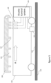
- FIG. 5 a schematic view of a shuttle 104 of a second embodiment of the invention, located underneath a lower surface 120 of a trolley 106, is shown, in which parts common to the embodiment of Figures 1 to 3 are denoted by like reference numerals but increased by 100.
- the shuttle moves 104 in the direction of arrow A until the location sensing device 122 views a position marker strip mounted on the floor 114 of the track 110 to detect the position of the shuttle 104 relative to the track 110.
- a series of proximity detectors 124 detect the presence of the lower surface 120 of the trolley 106 above by matching with a unique pattern of support webs 142 arranged on the underside 120 of the trolley 106.
- the sensors 124 only all move to the on state when they are aligned under the corresponding support webs 142 having the same spacing, and when this occurs, the location sensing device 122 is read so that the position of the base 120 of the trolley 106 relative to the track 110 can be determined, and the distance from this position to the back of the trolley and the front of the trolley can be determined by the shuttle control system 136.
- the trolleys 6, 106 can either be presented manually, or automatically via an AGV 10 ( Figure 3 ) to a queue input.
- the shuttle 4, 104 then moves to position a retracted connector device 26a under the trolley 6, 106 at the queue input, and then engages the trolley 6, 106 to pull the trolley 6, 106 into the queue 8.
- the connector device 26a disengages from the trolley 6, 106 to enable the shuttle 4, 104 to move away along the track 10, 110 to process other tasks.
- the shuttle 4, 104 positions its front connector device 26a behind the object, raises the connector device, and then pushes the trolley 6, 106 from the queue 8. This may move the trolley 6, 106 into engagement with an AGV 30, or into an open space beyond the end of the queue 8.
- trolleys 6, 106 In order to manage the position of trolleys 6, 106 in the queue 8 and maximise storage and throughput, it is necessary to move trolleys 6, 106 from the body of the queue 8 to take up free space which becomes available at the front of the queue 8 as trolleys 6, 106 are moved from the front of the queue 8. This then enables more trolleys 6, 106 to be added at the input end of the queue 8.
- the shuttle 4, 104 As the shuttle 4, 104 moves along the queue 8, it identifies the respective positions of trolleys 6, 106 along the queue by means of the trolley location sensing device 24, 124 and the position measurement system 22, 122. The shuttle 4, 104 can then move one or more trolleys 6, 106 from the body of the queue 8 towards the outfeed end of the queue 8 to free up space.
- the automatic guided vehicles 30 can be fitted with suitable attachments to guide and hold trolleys 6, 106 and then move between stations at the input and output ends of queues 8. Each station has a unique identifier at the input and output of each queue 8 since it is a transfer point for an automatic guided vehicle 30.
- the shuttle 4, 104 transfers a trolley 6, 106 from the automatic guided vehicle 30 into a queue 8, it adds the trolley's identity characteristic to an empty location in the queue table 44 for that queue 8, as shown in Figure 4 .
- the AGV 30 itself is effectively a queue 8 of length one, and when a trolley 6, 106 moves onto an AGV 30, the trolley characteristic moves from a queue table 44 to a location in corresponding AGV table 46.
- trolleys 6, 106 it is also possible to position trolleys 6, 106 in multiple rows prior to loading into road transport vehicles, for example as shown in Figure 3 .
- the queues 8 can be located side by side adjacent to loading bay doors so that transfer times between the queues 8 and the transport vehicles is minimised.
- the movement of trolleys 6, 106 between the automated guided vehicles 30 along the tracks 10, 110 can be carried out by the shuttles 4, 104.
- Figure 3 shows a representation of an unsorted queue 8a and two sorted queues 8, wherein trolleys 6, 106 having different characteristics are shown with different symbols 48, 50, 52.
- a trolley 6, 106 is delivered to the unsorted queue 8a by means of an automated guided vehicle 30, the identifying characteristic of the trolley 6, 106 having previously been detected and stored in the supervisory control system 32.
- the supervisory control system 32 then communicates and issues commands to the automated guided vehicles 30 and the automated shuttles 4, 104 to coordinate their operation.
- each queue 8, 8a identified by a queue identity
- the queue identity points to a queue table 44 which holds the current contents and logical position in the queue 8, 8a, as the actual physical position in the queue 8, 8a need only be known by the automated shuttle 4, 104.
- the supervisory controller 32 determines that there are two empty locations for trolley storage in queue B, and locations that are filled contain the characteristic identifier 48, 50, 52of the trolley type.
- This information can be used by the supervisory control system 32 ( Figure 6 ) to allocate trolleys 6, 106 to particular queues 8, 108, by means of the supervisory control system 32 being linked to a plurality of queue control systems 34 and AGV control systems 40.
- Each queue control system 34 is linked to multiple shuttle control systems 36, and the AGV supervisor system 38 is linked to multiple AGV control systems 40.
- wheels 18 can be provided on the tracks 10, 110 to enable containers without wheels to move along the tracks 10, 110.
Description
- The present invention relates to an object handling system, and relates particularly, but not exclusively, to an object handling system for use in a queuing system for goods.
- Objects such as trolleys, pallets or similar containers are often used to enable transfer of articles between different locations, for example where such articles are loaded into or unloaded from transport vehicles. Movement of trolleys or pallets is often carried out manually, or by means of forklift trucks, conveyor systems or automated guided vehicles. Within such systems, there is often a requirement to create a queue of objects. For example in one method, particularly for use with pallets, items are loaded onto an input end of a driven roller conveyor system and transferred automatically to an outfeed end by conveyor rollers. Items are prevented from leaving the outfeed end by a stop mechanism, as a result of which items queue up behind one another so that the first item to enter the queue is the first to leave. This arrangement suffers from the drawback that when an item is stopped on the conveyor, it must have a relatively smooth or low friction base, as the driven conveyor rollers continue to rotate, causing significant loading of the stop mechanism. In particular, the inertia generated by heavy items moving along the conveyor and being brought to rest by a stop mechanism results in high forces being applied to the stop mechanism during deceleration of the items. This problem can be partially mitigated by separating the conveyor into sections that are controlled and driven separately and using stop mechanisms with inbuilt dampers, but this significantly increases the cost and complexity of the handling system.
- In addition, object queues need to be positioned above floor level to provide sufficient space for motor drives and conveyor rollers and associated framework, as a result of which lift devices are often required to move items to the required height for entry into and exit from the object queue. Another alternative is to operate the queue totally manually at floor level. Operators push trolleys along a floor guide to assist in aligning the wheels correctly.
- These arrangements suffer from the drawback that manual involvement is required in order to enter trolleys into the input of the queue, remove trolleys from the queue, and move trolleys along the queue to eliminate empty spaces as trolleys are removed from the end of the queue.
- Preferred embodiments of the present invention seek to overcome one or more of the above disadvantages.
-
JP H10 105238 A claim 1. - According to the present invention, there is provided an object handling system as defined in
claim 1. - By enabling the apparatus to move along the track without engaging an object, this provides the advantage of enabling improved control of the position of objects, while also avoiding the necessity of large drive and stop mechanisms, thereby reducing the cost of the system. The engaging means may be moveable relative to an upper surface of a body of the apparatus between said first condition, in which the engaging means protrudes from the upper surface, and said second condition.
- This provides the advantage of enabling simple construction and operation of the engaging means.
- The engaging means may be adapted to engage an object adjacent a lower surface of said object.
- The second detector means may be adapted to detect a marker on a lower surface of at least one said object.
- The second detector means may include at least one proximity detector.
- This provides the advantage of enabling simple and inexpensive construction of the apparatus.
- The second detector means may include a plurality of proximity detectors adapted to detect a plurality of features on a lower surface of at least one said object.
- This provides the advantage of enabling simple and inexpensive construction of an accurate position detector.
- The first detector means may be adapted to detect the position of the apparatus relative to the track in response to detection of a said marker by said second detector means.
- This provides the advantage of reducing electrical power consumption by only operating the first detector means in the event of successful operation of the second detector means.
- The system comprises control means communicating with each said apparatus for controlling operation of said apparatus.
- At least one said container may be adapted to engage said track by means of wheels on at least one of said object and said track.
- At least one said container may be adapted to provide an identification signal to enable said control means to identify said object.
- The system may further comprise moving means for loading objects to and/or unloading objects from said track, wherein said moving means is adapted to communicate with said control means.
- At least one said object may be adapted to allow at least one said apparatus to pass thereunder when in said second condition.
- At least one said object may be a container for containing items.
- At least one said apparatus may be adapted to move at least one said object into and/or out of the system.
- A preferred embodiment of the invention will now be described, by way of example only and not in any limitative sense, with reference to the accompanying drawings in which:-
-
Figure 1 is a perspective view of trolleys and automated shuttles of an object handling system embodying the present invention; -
Figure 2 is a detailed perspective view of a shuttle ofFigure 1 of a first embodiment of the invention; -
Figure 3 is a schematic representation of a trolley process using the system ofFigure 1 ; -
Figure 4 shows queuing tables for use in the process ofFigure 3 ; -
Figure 5 is a side view of a shuttle of a second embodiment of the present invention and a side cross sectional view through a lower surface of a trolley; and -
Figure 6 is a schematic view of a control system of the object handling system ofFigure 1 . - Referring to
Figure 1 , anobject handing system 2 embodying the present invention has transport apparatus in the form ofautomated shuttles 4 and objects in the form ofwheeled trolleys 6 for containing articles and arranged inqueues 8 onrespective tracks 10. Theshuttles 4 havewheels 12 forengaging bases 14 oftracks 10 betweenrails 16 of the track, and thewheels 12 are driven by suitable drive means such as electric motors to enable theshuttle 4 to move in both directions along thetrack 10. Thetrolleys 6 havewheels 18 which engage therails 16 outwardly of thewheels 12 of theshuttles 4, and have elevatedlower surfaces 20 to enable theshuttles 4 to pass along thetrack 10 under thetrolleys 6. - As shown in greater detail in
Figure 2 , eachshuttle 4 has first detector means in the form of aposition detector 22 for indicating the position of theshuttle 4 on thetrack 10, and second detector means in the form of an objectlocation sensing device 24 for identifying a marker on thelower surface 20 of atrolley 6 to determine the position of eachtrolley 6 in itsrespective queue 8. Theshuttle 4 also has engaging means in the form of a pair ofconnector devices shuttle body 28 and moveable between a retractedposition 26a in which theshuttle 4 can move along thetrack 10 under thetrolleys 6 without engaging atrolley 6 and a protrudingposition 26b for engaging atrolley 6 to enable theshuttle 4 to move thetrolley 6 along thetrack 10. - Control means in the form of a control system 28 (
Figure 6 ) communicates with eachshuttle 4 to enable movement of theshuttles 4 to be controlled. Thesystem 2 also includes moving means in the form of automated guided vehicles (AGVs) 30 (Figure 3 ) forloading trolleys 6 onto thetracks 10 and unloadingtrolleys 6 from thetracks 10. The automated guidedvehicles 30 also communicate with thecontrol system 28 as shown in more detail inFigure 6 . Thecontrol system 28 has asupervisory control system 32 which can be used to supervise and coordinate operation ofmultiple queues 8 viaqueue control system 34, which controls individualshuttle control systems Figure 5 ) andAGV supervisor system 38 which controls individualAGV control systems 40 on each automated guidedvehicle 30, which can in turn be used to coordinate feeding oftrolleys 6 to and from thetracks 10. Thesupervisory control system 32 can also permit coordination ofmultiple shuttles 4 within thesame track 10, to permit simultaneous loading, unloading and movement oftrolleys 6 along aqueue 8. - Referring to
Figure 5 , a schematic view of ashuttle 104 of a second embodiment of the invention, located underneath alower surface 120 of atrolley 106, is shown, in which parts common to the embodiment ofFigures 1 to 3 are denoted by like reference numerals but increased by 100. The shuttle moves 104 in the direction of arrow A until thelocation sensing device 122 views a position marker strip mounted on thefloor 114 of thetrack 110 to detect the position of theshuttle 104 relative to thetrack 110. At the same time, a series ofproximity detectors 124 detect the presence of thelower surface 120 of thetrolley 106 above by matching with a unique pattern ofsupport webs 142 arranged on theunderside 120 of thetrolley 106. Thesensors 124 only all move to the on state when they are aligned under thecorresponding support webs 142 having the same spacing, and when this occurs, thelocation sensing device 122 is read so that the position of thebase 120 of thetrolley 106 relative to thetrack 110 can be determined, and the distance from this position to the back of the trolley and the front of the trolley can be determined by theshuttle control system 136. - The operation of the
system 2 will now be described. - In order to load
trolleys queue 8, thetrolleys Figure 3 ) to a queue input. Theshuttle connector device 26a under thetrolley trolley trolley queue 8. When thetrolley queue 8, theconnector device 26a disengages from thetrolley shuttle track - In order to unload
trolleys queue 8, theshuttle front connector device 26a behind the object, raises the connector device, and then pushes thetrolley queue 8. This may move thetrolley AGV 30, or into an open space beyond the end of thequeue 8. - In order to manage the position of
trolleys queue 8 and maximise storage and throughput, it is necessary to movetrolleys queue 8 to take up free space which becomes available at the front of thequeue 8 astrolleys queue 8. This then enablesmore trolleys queue 8. As theshuttle queue 8, it identifies the respective positions oftrolleys location sensing device position measurement system shuttle more trolleys queue 8 towards the outfeed end of thequeue 8 to free up space. - In order to transfer
trolleys queues 8, the automatic guidedvehicles 30 can be fitted with suitable attachments to guide and holdtrolleys queues 8. Each station has a unique identifier at the input and output of eachqueue 8 since it is a transfer point for an automatic guidedvehicle 30. When theshuttle trolley vehicle 30 into aqueue 8, it adds the trolley's identity characteristic to an empty location in the queue table 44 for thatqueue 8, as shown inFigure 4 . TheAGV 30 itself is effectively aqueue 8 of length one, and when atrolley AGV 30, the trolley characteristic moves from a queue table 44 to a location in corresponding AGV table 46. Similarly, when atrolley AGV 30 to aqueue 8, its characteristic is moved from the AGV table 46 to the queue table 44 using information in the queue identity table that links a station number to a queue identity. In this way, it is also possible to havemultiple shuttles same queue 8, in order to reduce the time taken for ashuttle queue 8. - It is also possible to position
trolleys Figure 3 . Thequeues 8 can be located side by side adjacent to loading bay doors so that transfer times between thequeues 8 and the transport vehicles is minimised. As shown inFigure 3 , it is also possible to haveintermediate queues 8a to assist in sorting trolleys intoqueues 8 of different categories, transfer between thequeues vehicles 30. The movement oftrolleys vehicles 30 along thetracks shuttles -
Figure 3 shows a representation of anunsorted queue 8a and twosorted queues 8, whereintrolleys different symbols trolley unsorted queue 8a by means of an automated guidedvehicle 30, the identifying characteristic of thetrolley supervisory control system 32. Thesupervisory control system 32 then communicates and issues commands to the automated guidedvehicles 30 and theautomated shuttles - In particular, the
input output position 56 of eachqueue Figure 4 . The queue identity points to a queue table 44 which holds the current contents and logical position in thequeue queue automated shuttle supervisory controller 32 that there are two empty locations for trolley storage in queue B, and locations that are filled contain thecharacteristic identifier Figure 6 ) to allocatetrolleys particular queues 8, 108, by means of thesupervisory control system 32 being linked to a plurality ofqueue control systems 34 andAGV control systems 40. Eachqueue control system 34 is linked to multipleshuttle control systems 36, and theAGV supervisor system 38 is linked to multipleAGV control systems 40. - It will be appreciated by persons skilled in the art that the above embodiments have been described by way of example only, and not in any limitative sense, and that various alterations and modifications are possible without departure from the scope of the invention as defined by the appended claims. For example, instead of providing
wheels 18 on thetrolleys tracks tracks
Claims (13)
- An object handling system (2) comprising:at least one object (6); andat least one transport apparatus (4) for transporting objects (6) in the object handling system (2);control means (28) communicating with each said apparatus (4) for controlling operation of said apparatus (4);wherein the at least one apparatus (4) comprises:drive means for moving the apparatus (4) along at least one track (10);engaging means (26a, 26b) having a first condition, in which the engaging means (26a, 26b) can engage a said object (6) to enable the apparatus (4) to move said object (6) along the track (10), and a second condition, in which the apparatus (4) can move along the track (10) without engaging said object (6);first detector means (22) for detecting a position of the apparatus (4) relative to the track (10);and characterised in that the at least one transport apparatus (4) comprises a second detector means (24) for detecting a position of the apparatus (4) relative to at least one said object (6) and in that the object handling system (2) comprises the at least one track (10) for receiving at least one said object (6) and at least one said apparatus (4).
- A system (2) according to claim 1, wherein the engaging means (26a, 26b) is moveable relative to an upper surface of a body (28) of the apparatus (4) between said first condition, in which the engaging means (26a, 26b) protrudes from the upper surface, and said second condition.
- A system (2) according to claim 1 or 2, wherein the engaging means (26a, 26b) is adapted to engage an object (6) adjacent a lower surface (20, 120) of said object (6).
- A system (2) according to any one of the preceding claims, wherein the second detector means (24) is adapted to detect a marker on a lower surface (20, 120) of at least one said object (6).
- A system (2) according to claim 4, wherein the first detector means (22) is adapted to detect the position of the apparatus (4) relative to the track (10) in response to detection of a said marker by said second detector means (24).
- A system (2) according to any one of the preceding claims, wherein the second detector means (24) includes at least one proximity detector.
- A system (2) according to claim 6, wherein the second detector means (24) includes a plurality of proximity detectors adapted to detect a plurality of features on a lower surface (20, 120) of at least one said object (6).
- A system (2) according to any preceding claim, wherein at least one said object (6) is adapted to engage said track (10) by means of wheels (18) on at least one of said object (6) and said track (10).
- A system (2) according to any preceding claim, wherein at least one said object (6) is adapted to provide an identification signal to enable said control means (28) to identify said object (6).
- A system (2) according to any preceding claim, further comprising moving means (30) for loading objects (6) to and/or unloading objects (6) from said track (10), wherein said moving means (30) is adapted to communicate with said control means (28).
- A system (2) according to any preceding claim, wherein at least one said object (6) is adapted to allow at least one said apparatus (4) to pass thereunder when in said second condition.
- A system (2) according to any preceding claim, wherein at least one said object (6) is a container for containing items.
- A system (2) according to any preceding claim, wherein at least one said apparatus (4) is adapted to move at least one said object (6) into and/or out of the system (2).
Priority Applications (1)
| Application Number | Priority Date | Filing Date | Title |
|---|---|---|---|
| EP18151646.9A EP3511271B1 (en) | 2018-01-15 | 2018-01-15 | Transport apparatus for object handling system, and object handling system incorporating such apparatus |
Applications Claiming Priority (1)
| Application Number | Priority Date | Filing Date | Title |
|---|---|---|---|
| EP18151646.9A EP3511271B1 (en) | 2018-01-15 | 2018-01-15 | Transport apparatus for object handling system, and object handling system incorporating such apparatus |
Publications (3)
| Publication Number | Publication Date |
|---|---|
| EP3511271A1 EP3511271A1 (en) | 2019-07-17 |
| EP3511271C0 EP3511271C0 (en) | 2024-01-03 |
| EP3511271B1 true EP3511271B1 (en) | 2024-01-03 |
Family
ID=60972128
Family Applications (1)
| Application Number | Title | Priority Date | Filing Date |
|---|---|---|---|
| EP18151646.9A Active EP3511271B1 (en) | 2018-01-15 | 2018-01-15 | Transport apparatus for object handling system, and object handling system incorporating such apparatus |
Country Status (1)
| Country | Link |
|---|---|
| EP (1) | EP3511271B1 (en) |
Families Citing this family (2)
| Publication number | Priority date | Publication date | Assignee | Title |
|---|---|---|---|---|
| CN111734148B (en) * | 2020-06-03 | 2022-03-11 | 中国核工业华兴建设有限公司 | Alternate hoisting method in semi-hollow U-shaped long and narrow space |
| DE102022113574A1 (en) * | 2022-05-30 | 2023-11-30 | Jungheinrich Aktiengesellschaft | Device for detecting a load carrier carried on an undercarriage shuttle |
Family Cites Families (6)
| Publication number | Priority date | Publication date | Assignee | Title |
|---|---|---|---|---|
| JPH09185409A (en) * | 1995-12-28 | 1997-07-15 | Shinko Electric Co Ltd | Unmanned vehicle system for wagon truck conveyance |
| JP3928193B2 (en) * | 1996-09-26 | 2007-06-13 | マツダ株式会社 | Trolley loading device |
| WO2005105620A1 (en) * | 2004-04-30 | 2005-11-10 | Yuyama Mfg. Co., Ltd. | Cart carrying apparatus |
| CN105009004B (en) * | 2013-01-28 | 2019-02-22 | 亚马逊科技公司 | Inventory system with attachable inventory's retainer |
| US9378482B1 (en) * | 2015-03-13 | 2016-06-28 | Amazon Technologies, Inc. | Exchange of containers |
| FR3039104B1 (en) * | 2015-07-22 | 2018-10-19 | Renault S.A.S | GUIDED AUTOMATIC VEHICLE FOR MULTIDIRECTIONAL DISPLACEMENT OF LOADS |
-
2018
- 2018-01-15 EP EP18151646.9A patent/EP3511271B1/en active Active
Also Published As
| Publication number | Publication date |
|---|---|
| EP3511271C0 (en) | 2024-01-03 |
| EP3511271A1 (en) | 2019-07-17 |
Similar Documents
| Publication | Publication Date | Title |
|---|---|---|
| US8989892B2 (en) | Apparatus and method for the defined intermediate storage and picking of produced articles of the same type but different size | |
| US10954065B2 (en) | Method and system for delivering items in delivery containers | |
| KR101857353B1 (en) | Rear Fork type Automated Guided Vehicle System | |
| US9008825B2 (en) | Container unloading system with auto-unload capability | |
| EP3511271B1 (en) | Transport apparatus for object handling system, and object handling system incorporating such apparatus | |
| KR100494404B1 (en) | Tote Conveyor System | |
| KR101884232B1 (en) | A logistics system including automatic driving truck and truck elevation system | |
| CN210392455U (en) | Transport rod assembly and cargo carrying and conveying mechanism applying same | |
| JP5447937B2 (en) | Goods transport equipment | |
| JP2010052878A (en) | Picking system | |
| CN109928123B (en) | Article accommodation apparatus | |
| GB1248260A (en) | Method and system of assembling a collection of articles selected from a plurality of stores | |
| CN213518331U (en) | Unmanned distribution system | |
| JP6627134B2 (en) | Automatic warehouse and trolley-type transfer equipment | |
| JP3568014B2 (en) | Article storage facility | |
| CN210392605U (en) | AGV carrier and use its conveying system | |
| JP7171992B2 (en) | Case transfer system and case transfer method | |
| US20060228203A1 (en) | Method for the takeover and/or handover and for the transport of goods | |
| JP3496824B2 (en) | Loading system | |
| JPS5841249B2 (en) | storage device | |
| JPS6293122A (en) | Automatic loading device for carried object | |
| JP4023292B2 (en) | Control device for moving body | |
| US20230394427A1 (en) | Conveying System, Method and Driverless Transport Vehicle for Transporting Components | |
| KR100195032B1 (en) | Car's Undercarriage Export System | |
| CN116113585A (en) | Trolley alignment device, distribution system and control method |
Legal Events
| Date | Code | Title | Description |
|---|---|---|---|
| PUAI | Public reference made under article 153(3) epc to a published international application that has entered the european phase |
Free format text: ORIGINAL CODE: 0009012 |
|
| STAA | Information on the status of an ep patent application or granted ep patent |
Free format text: STATUS: THE APPLICATION HAS BEEN PUBLISHED |
|
| AK | Designated contracting states |
Kind code of ref document: A1 Designated state(s): AL AT BE BG CH CY CZ DE DK EE ES FI FR GB GR HR HU IE IS IT LI LT LU LV MC MK MT NL NO PL PT RO RS SE SI SK SM TR |
|
| AX | Request for extension of the european patent |
Extension state: BA ME |
|
| STAA | Information on the status of an ep patent application or granted ep patent |
Free format text: STATUS: REQUEST FOR EXAMINATION WAS MADE |
|
| 17P | Request for examination filed |
Effective date: 20200110 |
|
| RBV | Designated contracting states (corrected) |
Designated state(s): AL AT BE BG CH CY CZ DE DK EE ES FI FR GB GR HR HU IE IS IT LI LT LU LV MC MK MT NL NO PL PT RO RS SE SI SK SM TR |
|
| STAA | Information on the status of an ep patent application or granted ep patent |
Free format text: STATUS: EXAMINATION IS IN PROGRESS |
|
| 17Q | First examination report despatched |
Effective date: 20220712 |
|
| GRAP | Despatch of communication of intention to grant a patent |
Free format text: ORIGINAL CODE: EPIDOSNIGR1 |
|
| STAA | Information on the status of an ep patent application or granted ep patent |
Free format text: STATUS: GRANT OF PATENT IS INTENDED |
|
| INTG | Intention to grant announced |
Effective date: 20230807 |
|
| GRAS | Grant fee paid |
Free format text: ORIGINAL CODE: EPIDOSNIGR3 |
|
| GRAA | (expected) grant |
Free format text: ORIGINAL CODE: 0009210 |
|
| STAA | Information on the status of an ep patent application or granted ep patent |
Free format text: STATUS: THE PATENT HAS BEEN GRANTED |
|
| AK | Designated contracting states |
Kind code of ref document: B1 Designated state(s): AL AT BE BG CH CY CZ DE DK EE ES FI FR GB GR HR HU IE IS IT LI LT LU LV MC MK MT NL NO PL PT RO RS SE SI SK SM TR |
|
| REG | Reference to a national code |
Ref country code: GB Ref legal event code: FG4D |
|
| REG | Reference to a national code |
Ref country code: DE Ref legal event code: R096 Ref document number: 602018063500 Country of ref document: DE |
|
| REG | Reference to a national code |
Ref country code: CH Ref legal event code: EP |
|
| REG | Reference to a national code |
Ref country code: IE Ref legal event code: FG4D |
|
| U01 | Request for unitary effect filed |
Effective date: 20240202 |
|
| U07 | Unitary effect registered |
Designated state(s): AT BE BG DE DK EE FI FR IT LT LU LV MT NL PT SE SI Effective date: 20240214 |
|
| U20 | Renewal fee paid [unitary effect] |
Year of fee payment: 7 Effective date: 20240212 |