EP3511247B1 - Foldable ram air inlet filter - Google Patents
Foldable ram air inlet filter Download PDFInfo
- Publication number
- EP3511247B1 EP3511247B1 EP19151431.4A EP19151431A EP3511247B1 EP 3511247 B1 EP3511247 B1 EP 3511247B1 EP 19151431 A EP19151431 A EP 19151431A EP 3511247 B1 EP3511247 B1 EP 3511247B1
- Authority
- EP
- European Patent Office
- Prior art keywords
- subassembly
- air
- assembly
- modulation panel
- inlet
- Prior art date
- Legal status (The legal status is an assumption and is not a legal conclusion. Google has not performed a legal analysis and makes no representation as to the accuracy of the status listed.)
- Active
Links
Images


Classifications
-
- B—PERFORMING OPERATIONS; TRANSPORTING
- B64—AIRCRAFT; AVIATION; COSMONAUTICS
- B64D—EQUIPMENT FOR FITTING IN OR TO AIRCRAFT; FLIGHT SUITS; PARACHUTES; ARRANGEMENT OR MOUNTING OF POWER PLANTS OR PROPULSION TRANSMISSIONS IN AIRCRAFT
- B64D13/00—Arrangements or adaptations of air-treatment apparatus for aircraft crew or passengers, or freight space
- B64D13/06—Arrangements or adaptations of air-treatment apparatus for aircraft crew or passengers, or freight space the air being conditioned
-
- B—PERFORMING OPERATIONS; TRANSPORTING
- B01—PHYSICAL OR CHEMICAL PROCESSES OR APPARATUS IN GENERAL
- B01D—SEPARATION
- B01D45/00—Separating dispersed particles from gases or vapours by gravity, inertia, or centrifugal forces
- B01D45/04—Separating dispersed particles from gases or vapours by gravity, inertia, or centrifugal forces by utilising inertia
- B01D45/08—Separating dispersed particles from gases or vapours by gravity, inertia, or centrifugal forces by utilising inertia by impingement against baffle separators
-
- B—PERFORMING OPERATIONS; TRANSPORTING
- B01—PHYSICAL OR CHEMICAL PROCESSES OR APPARATUS IN GENERAL
- B01D—SEPARATION
- B01D46/00—Filters or filtering processes specially modified for separating dispersed particles from gases or vapours
-
- B—PERFORMING OPERATIONS; TRANSPORTING
- B01—PHYSICAL OR CHEMICAL PROCESSES OR APPARATUS IN GENERAL
- B01D—SEPARATION
- B01D46/00—Filters or filtering processes specially modified for separating dispersed particles from gases or vapours
- B01D46/0002—Casings; Housings; Frame constructions
-
- B—PERFORMING OPERATIONS; TRANSPORTING
- B01—PHYSICAL OR CHEMICAL PROCESSES OR APPARATUS IN GENERAL
- B01D—SEPARATION
- B01D46/00—Filters or filtering processes specially modified for separating dispersed particles from gases or vapours
- B01D46/0002—Casings; Housings; Frame constructions
- B01D46/0016—Folded frame or housing constructions
-
- B—PERFORMING OPERATIONS; TRANSPORTING
- B01—PHYSICAL OR CHEMICAL PROCESSES OR APPARATUS IN GENERAL
- B01D—SEPARATION
- B01D46/00—Filters or filtering processes specially modified for separating dispersed particles from gases or vapours
- B01D46/0027—Filters or filtering processes specially modified for separating dispersed particles from gases or vapours with additional separating or treating functions
-
- B—PERFORMING OPERATIONS; TRANSPORTING
- B01—PHYSICAL OR CHEMICAL PROCESSES OR APPARATUS IN GENERAL
- B01D—SEPARATION
- B01D46/00—Filters or filtering processes specially modified for separating dispersed particles from gases or vapours
- B01D46/0039—Filters or filtering processes specially modified for separating dispersed particles from gases or vapours with flow guiding by feed or discharge devices
- B01D46/0041—Filters or filtering processes specially modified for separating dispersed particles from gases or vapours with flow guiding by feed or discharge devices for feeding
-
- B—PERFORMING OPERATIONS; TRANSPORTING
- B64—AIRCRAFT; AVIATION; COSMONAUTICS
- B64D—EQUIPMENT FOR FITTING IN OR TO AIRCRAFT; FLIGHT SUITS; PARACHUTES; ARRANGEMENT OR MOUNTING OF POWER PLANTS OR PROPULSION TRANSMISSIONS IN AIRCRAFT
- B64D33/00—Arrangement in aircraft of power plant parts or auxiliaries not otherwise provided for
- B64D33/02—Arrangement in aircraft of power plant parts or auxiliaries not otherwise provided for of combustion air intakes
-
- F—MECHANICAL ENGINEERING; LIGHTING; HEATING; WEAPONS; BLASTING
- F02—COMBUSTION ENGINES; HOT-GAS OR COMBUSTION-PRODUCT ENGINE PLANTS
- F02C—GAS-TURBINE PLANTS; AIR INTAKES FOR JET-PROPULSION PLANTS; CONTROLLING FUEL SUPPLY IN AIR-BREATHING JET-PROPULSION PLANTS
- F02C7/00—Features, components parts, details or accessories, not provided for in, or of interest apart form groups F02C1/00 - F02C6/00; Air intakes for jet-propulsion plants
- F02C7/04—Air intakes for gas-turbine plants or jet-propulsion plants
- F02C7/042—Air intakes for gas-turbine plants or jet-propulsion plants having variable geometry
-
- F—MECHANICAL ENGINEERING; LIGHTING; HEATING; WEAPONS; BLASTING
- F02—COMBUSTION ENGINES; HOT-GAS OR COMBUSTION-PRODUCT ENGINE PLANTS
- F02C—GAS-TURBINE PLANTS; AIR INTAKES FOR JET-PROPULSION PLANTS; CONTROLLING FUEL SUPPLY IN AIR-BREATHING JET-PROPULSION PLANTS
- F02C7/00—Features, components parts, details or accessories, not provided for in, or of interest apart form groups F02C1/00 - F02C6/00; Air intakes for jet-propulsion plants
- F02C7/04—Air intakes for gas-turbine plants or jet-propulsion plants
- F02C7/05—Air intakes for gas-turbine plants or jet-propulsion plants having provisions for obviating the penetration of damaging objects or particles
- F02C7/052—Air intakes for gas-turbine plants or jet-propulsion plants having provisions for obviating the penetration of damaging objects or particles with dust-separation devices
-
- B—PERFORMING OPERATIONS; TRANSPORTING
- B64—AIRCRAFT; AVIATION; COSMONAUTICS
- B64D—EQUIPMENT FOR FITTING IN OR TO AIRCRAFT; FLIGHT SUITS; PARACHUTES; ARRANGEMENT OR MOUNTING OF POWER PLANTS OR PROPULSION TRANSMISSIONS IN AIRCRAFT
- B64D13/00—Arrangements or adaptations of air-treatment apparatus for aircraft crew or passengers, or freight space
- B64D13/06—Arrangements or adaptations of air-treatment apparatus for aircraft crew or passengers, or freight space the air being conditioned
- B64D2013/0603—Environmental Control Systems
- B64D2013/0618—Environmental Control Systems with arrangements for reducing or managing bleed air, using another air source, e.g. ram air
-
- B—PERFORMING OPERATIONS; TRANSPORTING
- B64—AIRCRAFT; AVIATION; COSMONAUTICS
- B64D—EQUIPMENT FOR FITTING IN OR TO AIRCRAFT; FLIGHT SUITS; PARACHUTES; ARRANGEMENT OR MOUNTING OF POWER PLANTS OR PROPULSION TRANSMISSIONS IN AIRCRAFT
- B64D13/00—Arrangements or adaptations of air-treatment apparatus for aircraft crew or passengers, or freight space
- B64D13/06—Arrangements or adaptations of air-treatment apparatus for aircraft crew or passengers, or freight space the air being conditioned
- B64D2013/0603—Environmental Control Systems
- B64D2013/0651—Environmental Control Systems comprising filters, e.g. dust filters
-
- B—PERFORMING OPERATIONS; TRANSPORTING
- B64—AIRCRAFT; AVIATION; COSMONAUTICS
- B64D—EQUIPMENT FOR FITTING IN OR TO AIRCRAFT; FLIGHT SUITS; PARACHUTES; ARRANGEMENT OR MOUNTING OF POWER PLANTS OR PROPULSION TRANSMISSIONS IN AIRCRAFT
- B64D33/00—Arrangement in aircraft of power plant parts or auxiliaries not otherwise provided for
- B64D33/02—Arrangement in aircraft of power plant parts or auxiliaries not otherwise provided for of combustion air intakes
- B64D2033/022—Arrangement in aircraft of power plant parts or auxiliaries not otherwise provided for of combustion air intakes comprising bird or foreign object protections
-
- B—PERFORMING OPERATIONS; TRANSPORTING
- B64—AIRCRAFT; AVIATION; COSMONAUTICS
- B64D—EQUIPMENT FOR FITTING IN OR TO AIRCRAFT; FLIGHT SUITS; PARACHUTES; ARRANGEMENT OR MOUNTING OF POWER PLANTS OR PROPULSION TRANSMISSIONS IN AIRCRAFT
- B64D33/00—Arrangement in aircraft of power plant parts or auxiliaries not otherwise provided for
- B64D33/02—Arrangement in aircraft of power plant parts or auxiliaries not otherwise provided for of combustion air intakes
- B64D2033/0246—Arrangement in aircraft of power plant parts or auxiliaries not otherwise provided for of combustion air intakes comprising particle separators
-
- Y—GENERAL TAGGING OF NEW TECHNOLOGICAL DEVELOPMENTS; GENERAL TAGGING OF CROSS-SECTIONAL TECHNOLOGIES SPANNING OVER SEVERAL SECTIONS OF THE IPC; TECHNICAL SUBJECTS COVERED BY FORMER USPC CROSS-REFERENCE ART COLLECTIONS [XRACs] AND DIGESTS
- Y02—TECHNOLOGIES OR APPLICATIONS FOR MITIGATION OR ADAPTATION AGAINST CLIMATE CHANGE
- Y02T—CLIMATE CHANGE MITIGATION TECHNOLOGIES RELATED TO TRANSPORTATION
- Y02T50/00—Aeronautics or air transport
- Y02T50/50—On board measures aiming to increase energy efficiency
Definitions
- the present invention generally relates to air filters and, more particularly, to apparatus and methods for filtering RAM air of a vehicle.
- the aircraft Environmental Control System provides conditioned air and cabin pressurization for the crew, passengers and avionics. Failure of the ECS system can cause flight delay, flight cancellation and unscheduled maintenance. Data for the years 2012 to 2014 from Air China airlines show that for a fleet of one hundred twenty 737NG aircraft, due to ECS failure, the annual cost for maintenance was $3.3M and for dispatch was $1.1M. Further analysis reveals that most of the failures are due to overheating or parts wearing out in the Air Cycle Machine (ACM), which is the cooling pack of the ECS.
- ACM Air Cycle Machine
- a typical ACM removes the heat from the aircraft bleed air by heat exchangers and RAM air. Then, the conditioned air is distributed to the cabin. Water extracted from the air is sprayed to the heat exchangers to increase efficiency.
- a fan is installed in the RAM air path to increase air flow.
- ACM overheating is due to clogged heat exchangers (i.e., the primary and the secondary heat exchangers).
- dust debris peel out from the heat exchanger can damage the impeller of the fan.
- the fan rotates fast during ACM operation. Consequently, excessive vibration on the ACM shaft wears out the bearings and damages the ACM.
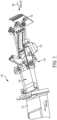
- FIG. 1 depicts a current RAM air inlet assembly 100.
- a RAM air 106 impinges an upstream deflector door 102.
- the deflector door 102 is moveable by an arm assembly 104 (downstream of the deflector door 102) that may include a series of tie-rods, link arms and torque shafts.
- the arm assembly can be actuated by an actuator 103.
- the arm assembly 104 can, via a modulation panel assembly 105 (downstream of the deflector door 102), move the deflector door 102.
- the RAM air 106 can continue through the inlet assembly 100 and into a RAM air duct 107.
- the actuator 103 When the actuator 103 retracts, it opens (i.e., lifts) the modulation panel assembly 105 and extends (i.e., lowers) the deflector door 102 into the flow of RAM air 106. During cruise flight, the deflector door 106 is folded.
- the modulation panel assembly 105 is controlled by the actuator 103 to adjust the RAM air 106 flow by changing the size of the cross section of the RAM air inlet.
- the actuator can open the modulation panel and extend the deflector door 102.
- the purpose of the deflector door is to prevent ice, slush, rocks and other unwanted material from going into the RAM air system.
- low weight particles, Catkins, and sands can still enter the RAM air system and clog the heat exchangers.
- Examples of prior designs of filter arrangements applicable to RAM air systems are disclosed in US Patent 2,976,952 , US Published Application US 2005/229558 , European Patent Application EP 1257468 , US Patent 2,381,705 , European Patent Application EP 0075054 , and European Patent Application EP 2995556 .
- the present invention provides apparatus and methods of filtering inlet air, such as RAM air, that may enter downstream components that are susceptible to particulate damage, such as heat exchangers.
- inlet air such as RAM air
- downstream components that are susceptible to particulate damage, such as heat exchangers.
- the present invention includes a filtering assembly that has an upstream modulation panel subassembly upon which an air flow may initially impinge.
- An air filter subassembly is downstream of the modulation panel.
- An arm subassembly can move the modulation panel subassembly which, in turn, can move the air filter subassembly into and out of the air flow.
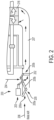
- FIG. 2 schematically depicts, in a general fashion and in accordance with an exemplary embodiment, a filtering assembly 200 that can receive, at an air inlet side 200a, an inlet air 206, such as a RAM air entering an aircraft or other vehicle.
- the assembly 200 may be configured to filter and then discharge the inlet air 206, at an air outlet side 200b, into an air duct 207.
- a component 216 (which is downstream of the assembly 200) may be susceptible to damage from particulates in the inlet air 206.
- the downstream component 216 is a heat exchanger.
- the heat exchanger is part of an environmental control system in a vehicle such as an aircraft.
- the assembly 200 may include an upstream modulation panel subassembly 205 configured and positioned at the inlet air side 200a where the inlet air 206 initially enters or impinges the assembly 200.
- the modulation panel subassembly 205 has a first (i.e., upstream) modulation panel 205a and a second (i.e., downstream) modulation panel 205b, according to embodiments.
- the first and second modulation panels 205a, 205b are configured to articulate with one another.
- the filtering assembly 200 further includes an air filter subassembly 202 that is downstream of the modulation panel subassembly 205 and downstream of the air inlet side 200a where the inlet air 206 initially enters or impinges the assembly 200.
- the air filter subassembly 202 is configured to discharge the inlet air 206 from the inlet air assembly 200 while positioned at the air outlet side 200b.
- the filtering assembly 200 includes an arm subassembly 204.
- An actuator 203 is upstream of the air filter subassembly 202.
- the actuator 203 may be directly connected with the arm subassembly 204.
- the actuator 203 may be indirectly connected with the filter subassembly 202. Consequently, in embodiments, the arm subassembly 204, via the actuator 203, can actuate the modulation panel subassembly 205. Concurrently, the arm subassembly 204, via the actuator 203, can actuate the air filter subassembly 202.
- FIGS. 3A-3B show another exemplary embodiment of a filtering assembly 300.
- the assembly 300 may be similar in design to the filtering assembly 200 and, therefore, reference numbers for components in the assembly 300 parallel the reference numbers for components in the assembly 200.
- the filtering assembly 300 in accordance with embodiments, includes an upstream modulation panel subassembly 305, a downstream air filter subassembly 302, an arm subassembly 304, and an actuator 303.
- the actuator 303 may be positioned at a lateral side of the assembly 300.
- the actuator 303 may be pneumatically operated and directly connected to the arm subassembly 304.
- the actuator 303 may also be indirectly connected, via the arm subassembly 304, to the both the modulation panel subassembly 305 and the filter subassembly 302. Thereby, the actuator 303 may actuate movement of the modulation panel subassembly 305 and the air filter subassembly 302. In embodiments, the actuated movement may be concurrent.
- the modulation panel subassembly 305 includes an upstream modulation panel 305a (adjacent the air inlet side 300a) and a downstream modulation panel 305b.
- the panels 305a, 305b are positioned in an end-to-end relationship and are configured to articulate about a hinge 308 between the panels. When articulated, the modulation panel subassembly 305 can move between a folded position and an extended (i.e., flat) position. In FIGS. 3A-3B , the panel subassembly 305 is shown in a folded position.
- the arm subassembly 304 may include a series of rods, linkage arms, and shafts, according to embodiments.
- One portion (e.g., half) of the arm subassembly 304 may extend, between the air inlet side 300a and the air outlet side 300b, along one side of the modulation panel subassembly 305.
- Another portion (e.g., another half) of the arm subassembly 304 may extend, between the air inlet side 300a and the air outlet side 300b, along an opposite side of the modulation panel subassembly 305.
- each of the foregoing portions e.g., halves
- the arm subassembly 304 may include an actuating arm 304a connected to the actuator 303.
- the actuating arm 304a may be linked to a rotating shaft 304c that is supported by a pair of supports 311a, 311b, of which one or both may be affixed to an interior of an air duct 307.
- the rotating shaft 304c may be affixed to a pair of linkage arms 304b.
- a pair of supports 304e, affixed to the modulation panel subassembly 305 may support the linkage arms 304b.
- the pair of linkage arms 304b may be respectively connected to, at one ends thereof, a pair of connecting rods 304f of the arm subassembly 304, in embodiments. At the other ends thereof, a rotating shaft 304d may be connected to the connecting rods 304f.
- a pair of supports 310a, 310b may support the shaft 304d and be affixed to the interior of the air duct 307.
- the connecting rods 304f may connect, via linkage arms 304g, to the air filter subassembly 302.
- arm subassembly 304 is affixed, via the supports 304e, to the modulation panel subassembly 305.
- the supports 304e may be affixed to the upstream modulation panel 305a.
- the modulation panel 305a articulates about the hinge 308.
- the modulation panel 305b articulates about the hinge 308.
- the articulation about the hinge 308 moves the panels 305a, 305b between a folded position and an extended position.
- the shaft 304d may concurrently rotate.
- the air filter subassembly 302 may rotate about the shaft 304d.
- the rotation of the air filter subassembly 302 may cause it to move between a folded position and an extended position (depicted by the arrow in FIG. 2 ). Moving between the folded and extended positions enables the air filter subassembly to move into and out of the flow of inlet air 306.
- FIG. 4 depicts an exemplary embodiment of the air filter subassembly 302 which can have a filter 302a supported by a meshed plate 302b.
- the filter 302a can be removed and replaced from the meshed plate 302b.
- the present invention can be utilized in the following fashion: Airplane Position Flap Position Modulation Panel Position Filter Position On Ground Up or Down Full Open Extended Takeoff Down Normal Open Extended Climb Up Moves Toward Closed Position Retracted Cruise Up Modulates Between Normal Open & Closed Retracted Approach Down Moves to Normal Open Extended Touchdown Down Drives to Full Open Drives to Full Extend
Landscapes
- Engineering & Computer Science (AREA)
- Chemical & Material Sciences (AREA)
- Combustion & Propulsion (AREA)
- Chemical Kinetics & Catalysis (AREA)
- Aviation & Aerospace Engineering (AREA)
- Pulmonology (AREA)
- Health & Medical Sciences (AREA)
- General Health & Medical Sciences (AREA)
- Mechanical Engineering (AREA)
- General Engineering & Computer Science (AREA)
- Physics & Mathematics (AREA)
- Geometry (AREA)
- Cooling, Air Intake And Gas Exhaust, And Fuel Tank Arrangements In Propulsion Units (AREA)
- Filtering Of Dispersed Particles In Gases (AREA)
Description
- The present invention generally relates to air filters and, more particularly, to apparatus and methods for filtering RAM air of a vehicle.
- On modern commercial aircraft, the aircraft Environmental Control System (ECS) provides conditioned air and cabin pressurization for the crew, passengers and avionics. Failure of the ECS system can cause flight delay, flight cancellation and unscheduled maintenance. Data for the years 2012 to 2014 from Air China airlines show that for a fleet of one hundred twenty 737NG aircraft, due to ECS failure, the annual cost for maintenance was $3.3M and for dispatch was $1.1M. Further analysis reveals that most of the failures are due to overheating or parts wearing out in the Air Cycle Machine (ACM), which is the cooling pack of the ECS.
- A typical ACM removes the heat from the aircraft bleed air by heat exchangers and RAM air. Then, the conditioned air is distributed to the cabin. Water extracted from the air is sprayed to the heat exchangers to increase efficiency. A fan is installed in the RAM air path to increase air flow.
- ACM overheating is due to clogged heat exchangers (i.e., the primary and the secondary heat exchangers). In addition, dust debris peel out from the heat exchanger can damage the impeller of the fan. The fan rotates fast during ACM operation. Consequently, excessive vibration on the ACM shaft wears out the bearings and damages the ACM.
- There is no specific way to know, from outside of the aircraft, whether the heat exchangers are clogged. Only during scheduled maintenance will the heat exchanger inlet inspection/clean-out panel be opened for visual inspection.
-
FIG. 1 depicts a current RAMair inlet assembly 100. ARAM air 106 impinges anupstream deflector door 102. Thedeflector door 102 is moveable by an arm assembly 104 (downstream of the deflector door 102) that may include a series of tie-rods, link arms and torque shafts. The arm assembly can be actuated by anactuator 103. Thearm assembly 104 can, via a modulation panel assembly 105 (downstream of the deflector door 102), move thedeflector door 102. TheRAM air 106 can continue through theinlet assembly 100 and into aRAM air duct 107. - When the
actuator 103 retracts, it opens (i.e., lifts) themodulation panel assembly 105 and extends (i.e., lowers) thedeflector door 102 into the flow ofRAM air 106. During cruise flight, thedeflector door 106 is folded. Themodulation panel assembly 105 is controlled by theactuator 103 to adjust theRAM air 106 flow by changing the size of the cross section of the RAM air inlet. - When aircraft flaps are deployed during takeoff, or approach/landing, or the aircraft is on ground, the actuator can open the modulation panel and extend the
deflector door 102. - The purpose of the deflector door is to prevent ice, slush, rocks and other unwanted material from going into the RAM air system. However, low weight particles, Catkins, and sands can still enter the RAM air system and clog the heat exchangers. Examples of prior designs of filter arrangements applicable to RAM air systems are disclosed in
US Patent 2,976,952 ,US Published Application US 2005/229558 ,European Patent Application EP 1257468 ,US Patent 2,381,705 ,European Patent Application EP 0075054 , and European Patent ApplicationEP 2995556 . - As can be seen, there is a need for improved apparatus and methods to minimize clogging and damage to heat exchangers downstream of air inlets.
- The present invention is defined by the independent claims, to which reference should now be made. Advantageous embodiments are set out in the dependent claims.
- These and other features, aspects and advantages of the present invention will become better understood with reference to the following drawings, description and claims.
-
-
FIG. 1 is a perspective view of a prior air inlet assembly having a deflector door; -
FIG. 2 is a schematic diagram of an air inlet assembly having a filter subassembly according to an embodiment of the present invention; -
FIGS. 3A-3B are perspective views an air inlet assembly having a filter subassembly according to another embodiment of the present invention; -
FIG. 4 is an exploded perspective view of a filter subassembly according to an embodiment of the present invention. - The following detailed description is of the best currently contemplated modes of carrying out the invention. The description is not to be taken in a limiting sense, but is made merely for the purpose of illustrating the general principles of the invention, since the scope of the invention is best defined by the appended claims.
- Various features are described below that can each be used independently of one another or in combination with other features. However, any single feature may not address any of the problems discussed above or may only address one of the problems discussed above. Further, one or more of the problems discussed above may not be fully addressed by any of the features described below.
- Broadly, the present invention provides apparatus and methods of filtering inlet air, such as RAM air, that may enter downstream components that are susceptible to particulate damage, such as heat exchangers. Although the present invention is described in the context of aircraft, the present invention contemplates that it can be implemented in other vehicles and contexts.
- Generally, the present invention includes a filtering assembly that has an upstream modulation panel subassembly upon which an air flow may initially impinge. An air filter subassembly is downstream of the modulation panel. An arm subassembly can move the modulation panel subassembly which, in turn, can move the air filter subassembly into and out of the air flow.
-
FIG. 2 schematically depicts, in a general fashion and in accordance with an exemplary embodiment, afiltering assembly 200 that can receive, at anair inlet side 200a, aninlet air 206, such as a RAM air entering an aircraft or other vehicle. In embodiments, theassembly 200 may be configured to filter and then discharge theinlet air 206, at anair outlet side 200b, into anair duct 207. In theair duct 207, a component 216 (which is downstream of the assembly 200) may be susceptible to damage from particulates in theinlet air 206. For example, thedownstream component 216 is a heat exchanger. In embodiments, the heat exchanger is part of an environmental control system in a vehicle such as an aircraft. - The
assembly 200 may include an upstreammodulation panel subassembly 205 configured and positioned at theinlet air side 200a where theinlet air 206 initially enters or impinges theassembly 200. In embodiments, themodulation panel subassembly 205 has a first (i.e., upstream)modulation panel 205a and a second (i.e., downstream)modulation panel 205b, according to embodiments. The first andsecond modulation panels - The
filtering assembly 200 further includes anair filter subassembly 202 that is downstream of the modulation panel subassembly 205 and downstream of theair inlet side 200a where theinlet air 206 initially enters or impinges theassembly 200. Theair filter subassembly 202 is configured to discharge theinlet air 206 from theinlet air assembly 200 while positioned at theair outlet side 200b. - Having the
air filter subassembly 202 positioned at theoutlet side 200b, rather than at theinlet side 200a, enables theair filter subassembly 202 to better cover the entire cross section of theair duct 207 through which the inlet air flows. - The
filtering assembly 200 includes anarm subassembly 204. Anactuator 203 is upstream of theair filter subassembly 202. In embodiments, theactuator 203 may be directly connected with thearm subassembly 204. Also, theactuator 203 may be indirectly connected with thefilter subassembly 202. Consequently, in embodiments, thearm subassembly 204, via theactuator 203, can actuate themodulation panel subassembly 205. Concurrently, thearm subassembly 204, via theactuator 203, can actuate theair filter subassembly 202. -
FIGS. 3A-3B show another exemplary embodiment of afiltering assembly 300. Theassembly 300 may be similar in design to thefiltering assembly 200 and, therefore, reference numbers for components in theassembly 300 parallel the reference numbers for components in theassembly 200. - Like the
filtering assembly 200, thefiltering assembly 300, in accordance with embodiments, includes an upstreammodulation panel subassembly 305, a downstreamair filter subassembly 302, anarm subassembly 304, and anactuator 303. - The
actuator 303 may be positioned at a lateral side of theassembly 300. In embodiments, theactuator 303 may be pneumatically operated and directly connected to thearm subassembly 304. Theactuator 303 may also be indirectly connected, via thearm subassembly 304, to the both themodulation panel subassembly 305 and thefilter subassembly 302. Thereby, theactuator 303 may actuate movement of themodulation panel subassembly 305 and theair filter subassembly 302. In embodiments, the actuated movement may be concurrent. - The
modulation panel subassembly 305 includes anupstream modulation panel 305a (adjacent theair inlet side 300a) and adownstream modulation panel 305b. Thepanels hinge 308 between the panels. When articulated, themodulation panel subassembly 305 can move between a folded position and an extended (i.e., flat) position. InFIGS. 3A-3B , thepanel subassembly 305 is shown in a folded position. - The
arm subassembly 304 may include a series of rods, linkage arms, and shafts, according to embodiments. One portion (e.g., half) of thearm subassembly 304 may extend, between theair inlet side 300a and theair outlet side 300b, along one side of themodulation panel subassembly 305. Another portion (e.g., another half) of thearm subassembly 304 may extend, between theair inlet side 300a and theair outlet side 300b, along an opposite side of themodulation panel subassembly 305. In embodiments, each of the foregoing portions (e.g., halves) may be symmetrically designed. - In embodiments, the
arm subassembly 304 may include anactuating arm 304a connected to theactuator 303. In thearm subassembly 304, theactuating arm 304a may be linked to arotating shaft 304c that is supported by a pair ofsupports air duct 307. Therotating shaft 304c may be affixed to a pair oflinkage arms 304b. In turn, a pair ofsupports 304e, affixed to themodulation panel subassembly 305, may support thelinkage arms 304b. - The pair of
linkage arms 304b may be respectively connected to, at one ends thereof, a pair of connectingrods 304f of thearm subassembly 304, in embodiments. At the other ends thereof, arotating shaft 304d may be connected to the connectingrods 304f. A pair ofsupports shaft 304d and be affixed to the interior of the air duct 307.The connectingrods 304f may connect, vialinkage arms 304g, to theair filter subassembly 302. - As noted above,
arm subassembly 304 is affixed, via thesupports 304e, to themodulation panel subassembly 305. In embodiments, thesupports 304e may be affixed to theupstream modulation panel 305a. Thereby, when theactuator 303 moves theactuator arm 304a, and theshaft 304c rotates, themodulation panel 305a articulates about thehinge 308. In turn, themodulation panel 305b articulates about thehinge 308. In embodiments, as noted above, the articulation about thehinge 308 moves thepanels - In embodiments, as the
shaft 304c rotates, theshaft 304d may concurrently rotate. In turn, theair filter subassembly 302 may rotate about theshaft 304d. The rotation of theair filter subassembly 302 may cause it to move between a folded position and an extended position (depicted by the arrow inFIG. 2 ). Moving between the folded and extended positions enables the air filter subassembly to move into and out of the flow ofinlet air 306. - It can be advantageous to have the
air filter subassembly 302 rotate towards the upstream side of thefiltering assembly 300 and into the folded position (FIG. 2 ). This can prevent particles captured by theair filter subassembly 202 from falling back into the inlet air flow. -
FIG. 4 depicts an exemplary embodiment of theair filter subassembly 302 which can have afilter 302a supported by ameshed plate 302b. In embodiments, thefilter 302a can be removed and replaced from themeshed plate 302b. - As an example, the present invention can be utilized in the following fashion:
Airplane Position Flap Position Modulation Panel Position Filter Position On Ground Up or Down Full Open Extended Takeoff Down Normal Open Extended Climb Up Moves Toward Closed Position Retracted Cruise Up Modulates Between Normal Open & Closed Retracted Approach Down Moves to Normal Open Extended Touchdown Down Drives to Full Open Drives to Full Extend - It should be understood, of course, that the foregoing relates to exemplary embodiments of the invention and that modifications may be made without departing from the scope of the invention as set forth in the following claims.
Claims (8)
- A vehicle filtering assembly configured to receive an inlet air (206), the filtering assembly comprising a modulation panel subassembly (205), an air filter subassembly (202), an actuator (203), and an arm subassembly (204), wherein:the modulation panel subassembly includes a first upstream modulation panel (205a) and a second downstream modulation panel (205b), where the first upstream and second downstream modulation panels (205a, 205b) are configured to articulate with one another to move the modulation panel subassembly between a folded position and an extended position;the air filter subassembly (202) is downstream of the modulation panel subassembly (205);the air filter subassembly (202) is configured to discharge the inlet air (206) from the filtering assembly while positioned at an air outlet side (200b);the actuator (203) is upstream of the air filter subassembly (202) and connected with the arm subassembly; andthe arm subassembly (204) is configured to, via the actuator, move the modulation panel subassembly (205) between the folded position and the extended position to move the first and second modulation panels into and out of the flow of inlet air to change a size of a cross-section of an air inlet into an air duct (207), and to move the air filter subassembly into and out of a flow of the inlet air,wherein the first upstream modulation panel and the second downstream modulation panel (205a, 205b) are positioned in an end-to-end relationship, characterised in thatthe first upstream modulation panel and the second downstream modulation panel (205a, 205b) are configured to articulate about a hinge between the first upstream modulation panel and the second downstream modulation panel (205a, 205b).
- The assembly of claim 1, further comprising the actuator (203) directly connected to the arm subassembly.
- The assembly of claim 1, further comprising the actuator (203) indirectly connected to the air filter subassembly.
- The assembly of claim 1, wherein the modulation panel subassembly (205) is configured to articulate.
- The assembly of claim 1, wherein the assembly is configured to direct the inlet air (206) through the air duct (207) and to a component downstream of the assembly, wherein the component is susceptible to damage from particulates in the inlet air (206).
- The assembly of claim 1, wherein the air filter subassembly (202) is configured to move between a folded position and an extended position.
- The assembly of claim 6, wherein the air filter subassembly (202) is configured to rotate towards an upstream side of the filter assembly and into the folded position.
- A method of filtering inlet air for a vehicle, the method comprising:providing the assembly of claim 1; andmoving the modulation panel subassembly (205) between the folded position and the extended position to move the first and second modulation panels into and out of the flow of inlet air to change the size of the cross-section of the air inlet into the air duct (207), and to move the air filter subassembly into and out of the flow of the inlet air.
Applications Claiming Priority (1)
| Application Number | Priority Date | Filing Date | Title |
|---|---|---|---|
| US15/869,638 US11111024B2 (en) | 2018-01-12 | 2018-01-12 | Foldable RAM air inlet filter |
Publications (2)
| Publication Number | Publication Date |
|---|---|
| EP3511247A1 EP3511247A1 (en) | 2019-07-17 |
| EP3511247B1 true EP3511247B1 (en) | 2023-06-14 |
Family
ID=65019409
Family Applications (1)
| Application Number | Title | Priority Date | Filing Date |
|---|---|---|---|
| EP19151431.4A Active EP3511247B1 (en) | 2018-01-12 | 2019-01-11 | Foldable ram air inlet filter |
Country Status (3)
| Country | Link |
|---|---|
| US (1) | US11111024B2 (en) |
| EP (1) | EP3511247B1 (en) |
| CN (1) | CN110027714B (en) |
Families Citing this family (2)
| Publication number | Priority date | Publication date | Assignee | Title |
|---|---|---|---|---|
| US11866169B2 (en) * | 2020-08-07 | 2024-01-09 | Textron Innovations Inc. | System and method for supplying passively filtered ram air to a hydrogen fuel cell of a UAV |
| EP4714829A1 (en) * | 2024-09-18 | 2026-03-25 | Airbus Operations, S.L.U. | Ram air inlet assembly |
Citations (1)
| Publication number | Priority date | Publication date | Assignee | Title |
|---|---|---|---|---|
| EP1257468B1 (en) * | 2000-02-25 | 2004-12-08 | Honeywell International Inc. | Inlet vortex bustor and ice protector for auxiliary power units |
Family Cites Families (33)
| Publication number | Priority date | Publication date | Assignee | Title |
|---|---|---|---|---|
| USRE22656E (en) | 1945-07-31 | Filter control fob aircraft engines | ||
| US2381705A (en) | 1942-06-11 | 1945-08-07 | Vokes Cecil Gordon | Filter |
| US2976952A (en) | 1956-07-09 | 1961-03-28 | Jr Raymond Prunty Holland | Anti-ingestion means for turbojet aircraft |
| US3449891A (en) | 1966-11-15 | 1969-06-17 | United Aircraft Corp | Engine inlet air particle separator |
| US3421296A (en) | 1966-11-15 | 1969-01-14 | United Aircraft Corp | Engine inlet air particle separator |
| US4250703A (en) | 1979-03-15 | 1981-02-17 | Avco Corporation | Swinging door particle separator and deicing system |
| US4312645A (en) * | 1980-03-10 | 1982-01-26 | Parmatic Filter Corporation | Separator assembly |
| DE3173718D1 (en) | 1981-09-23 | 1986-03-20 | Parmatic Filter Corp | Improved separator assembly |
| US4698078A (en) * | 1985-10-02 | 1987-10-06 | Parmatic Filter Corporation | Separator assembly |
| US5064457A (en) * | 1991-02-01 | 1991-11-12 | Vwe, Inc. | Particulate containment control system |
| US5697394A (en) | 1993-03-02 | 1997-12-16 | United Technologies Corporation | Low observable engine air inlet system |
| US7192462B2 (en) | 2004-04-14 | 2007-03-20 | Aerospace Filtration Systems, Inc. | Engine air filter and sealing system |
| FR2879564B1 (en) * | 2004-12-20 | 2008-05-16 | Airbus France Sas | VENTILATION AIR ENTRY ARRANGEMENT WITH MOBILE SHUTTER ELEMENT |
| US7300494B2 (en) * | 2005-02-24 | 2007-11-27 | Hamilton Sundstrand Corporation | On-board inert gas generation system with compressor surge protection |
| US7491253B2 (en) | 2005-05-31 | 2009-02-17 | Aerospace Filtrations Systems, Inc. | Engine intake system with accessible, interchangeable air filters |
| US7575014B2 (en) | 2005-07-29 | 2009-08-18 | Aerospace Filtration Systems, Inc. | Control of engine intake door |
| EP2040818A2 (en) | 2006-07-14 | 2009-04-01 | Aerospace Filtration Systems, Inc. | Aircraft engine inlet pivotable barrier filter |
| US7618006B2 (en) | 2006-11-13 | 2009-11-17 | The Boeing Company | Ram air inlets for use with aircraft environmental control systems and other aircraft and non-aircraft systems |
| FR2924471B1 (en) * | 2007-11-30 | 2013-11-01 | Eurocopter France | AIR INTAKE OF A TURBOMOTEUR WITH A CONTROLLED FILTRATION SYSTEM |
| US7837753B2 (en) * | 2007-11-30 | 2010-11-23 | Honeywell International Inc. | Systems for filtering particles from an airflow |
| DE102008026117A1 (en) * | 2008-05-30 | 2009-12-10 | Airbus Deutschland Gmbh | Fresh air intake for an aircraft |
| EP2382026B1 (en) | 2008-12-26 | 2017-08-23 | Rolls-Royce North American Technologies, Inc. | Inlet particle separator system for a gas turbine engine |
| EP2743178B1 (en) * | 2012-12-11 | 2016-08-17 | AIRBUS HELICOPTERS DEUTSCHLAND GmbH | An air inlet combining a filter and a bypass device for use with a turbine engine |
| US10072664B2 (en) | 2012-12-19 | 2018-09-11 | Hamilton Sundstrand Corporation | Debris filter for motor cooling inlet on ram air fan |
| EP2957503B1 (en) * | 2014-06-19 | 2016-08-17 | AIRBUS HELICOPTERS DEUTSCHLAND GmbH | Aircraft with two engines having by-pass air inlet openings and bleed air outlets as well as engine for an aircraft |
| EP2995556B1 (en) * | 2014-09-12 | 2018-11-07 | AIRBUS HELICOPTERS DEUTSCHLAND GmbH | An aircraft with an air intake for an air breathing propulsion engine |
| US20160146511A1 (en) | 2014-11-24 | 2016-05-26 | Hamilton Sundstrand Corporation | Heat exchanger assembly for aircraft ecs |
| US9719352B2 (en) * | 2014-12-17 | 2017-08-01 | Honeywell International Inc. | Compartment based inlet particle separator system |
| US9879591B2 (en) * | 2015-02-20 | 2018-01-30 | Pratt & Whitney Canada Corp. | Engine intake assembly with selector valve |
| ITBO20150232A1 (en) * | 2015-05-05 | 2016-11-05 | Bmc Srl | AIRCRAFT WITH ENGINE EQUIPPED WITH AIR INTAKE FILTER |
| US10023296B2 (en) * | 2016-08-09 | 2018-07-17 | Bell Helicopter Textron Inc. | Inlet duct selector for tiltrotor barrier filter |
| US20180306112A1 (en) * | 2017-04-20 | 2018-10-25 | General Electric Company | System and Method for Regulating Flow in Turbomachines |
| IT201700044153A1 (en) * | 2017-04-21 | 2018-10-21 | Bmc Srl | AIR INTAKE UNIT FOR AN AIRCRAFT PROPELLER AND EQUIPPED WITH AN AIR FILTER AND A AIR FILTER BYPASS DUCT |
-
2018
- 2018-01-12 US US15/869,638 patent/US11111024B2/en active Active
-
2019
- 2019-01-11 EP EP19151431.4A patent/EP3511247B1/en active Active
- 2019-01-14 CN CN201910034790.8A patent/CN110027714B/en active Active
Patent Citations (1)
| Publication number | Priority date | Publication date | Assignee | Title |
|---|---|---|---|---|
| EP1257468B1 (en) * | 2000-02-25 | 2004-12-08 | Honeywell International Inc. | Inlet vortex bustor and ice protector for auxiliary power units |
Also Published As
| Publication number | Publication date |
|---|---|
| CN110027714A (en) | 2019-07-19 |
| US20190217959A1 (en) | 2019-07-18 |
| US11111024B2 (en) | 2021-09-07 |
| CN110027714B (en) | 2024-08-06 |
| EP3511247A1 (en) | 2019-07-17 |
Similar Documents
| Publication | Publication Date | Title |
|---|---|---|
| US8973867B2 (en) | Fresh air inlet for an aircraft | |
| US6634597B2 (en) | Method and apparatus for controlling aircraft airflow | |
| EP1910168B1 (en) | Control of engine intake door | |
| EP2969764B1 (en) | Interchangeable inlet protection systems for air intakes of aircraft engines and related methods | |
| US7886520B2 (en) | Gas turbine engine | |
| CN101939222B (en) | Engine intake flap for being arranged on the housing of an air intake of an aircraft engine, as well as engine with such an engine intake flap and aircraft system | |
| US3483676A (en) | Helicopter engine air inlets | |
| EP1504993B1 (en) | Air conditioning system of a passenger aircraft | |
| EP2853485B1 (en) | Apparatus and methods to operate laminar flow control doors | |
| EP3511247B1 (en) | Foldable ram air inlet filter | |
| EP2860113B1 (en) | Engine mounted inlet plenum for a rotorcraft | |
| US7600714B2 (en) | Diffusing air inlet door assembly | |
| EP3106721B1 (en) | Multi-flapper check valve without center supports | |
| EP2280869A1 (en) | Device and method for cooling exhaust air of aircraft air-conditioning systems | |
| EP3560837A1 (en) | Passive particle separation system | |
| US11542028B2 (en) | Aircraft comprising an air intake | |
| CA2329343C (en) | Jet engine exhaust nozzle | |
| US20020109048A1 (en) | Tailored wing assembly for an aircraft moveable slat system | |
| EP3023330B1 (en) | Heat exchanger assembly for aircraft ecs | |
| US11525398B2 (en) | Engine inlet with deployable particle separator | |
| CN111071458B (en) | Bypass turbofan engine and aircraft |
Legal Events
| Date | Code | Title | Description |
|---|---|---|---|
| PUAI | Public reference made under article 153(3) epc to a published international application that has entered the european phase |
Free format text: ORIGINAL CODE: 0009012 |
|
| STAA | Information on the status of an ep patent application or granted ep patent |
Free format text: STATUS: THE APPLICATION HAS BEEN PUBLISHED |
|
| AK | Designated contracting states |
Kind code of ref document: A1 Designated state(s): AL AT BE BG CH CY CZ DE DK EE ES FI FR GB GR HR HU IE IS IT LI LT LU LV MC MK MT NL NO PL PT RO RS SE SI SK SM TR |
|
| AX | Request for extension of the european patent |
Extension state: BA ME |
|
| STAA | Information on the status of an ep patent application or granted ep patent |
Free format text: STATUS: REQUEST FOR EXAMINATION WAS MADE |
|
| 17P | Request for examination filed |
Effective date: 20190726 |
|
| RBV | Designated contracting states (corrected) |
Designated state(s): AL AT BE BG CH CY CZ DE DK EE ES FI FR GB GR HR HU IE IS IT LI LT LU LV MC MK MT NL NO PL PT RO RS SE SI SK SM TR |
|
| STAA | Information on the status of an ep patent application or granted ep patent |
Free format text: STATUS: EXAMINATION IS IN PROGRESS |
|
| 17Q | First examination report despatched |
Effective date: 20201028 |
|
| GRAP | Despatch of communication of intention to grant a patent |
Free format text: ORIGINAL CODE: EPIDOSNIGR1 |
|
| STAA | Information on the status of an ep patent application or granted ep patent |
Free format text: STATUS: GRANT OF PATENT IS INTENDED |
|
| INTG | Intention to grant announced |
Effective date: 20230206 |
|
| GRAS | Grant fee paid |
Free format text: ORIGINAL CODE: EPIDOSNIGR3 |
|
| GRAA | (expected) grant |
Free format text: ORIGINAL CODE: 0009210 |
|
| STAA | Information on the status of an ep patent application or granted ep patent |
Free format text: STATUS: THE PATENT HAS BEEN GRANTED |
|
| AK | Designated contracting states |
Kind code of ref document: B1 Designated state(s): AL AT BE BG CH CY CZ DE DK EE ES FI FR GB GR HR HU IE IS IT LI LT LU LV MC MK MT NL NO PL PT RO RS SE SI SK SM TR |
|
| P01 | Opt-out of the competence of the unified patent court (upc) registered |
Effective date: 20230421 |
|
| REG | Reference to a national code |
Ref country code: CH Ref legal event code: EP |
|
| REG | Reference to a national code |
Ref country code: DE Ref legal event code: R096 Ref document number: 602019030883 Country of ref document: DE |
|
| REG | Reference to a national code |
Ref country code: AT Ref legal event code: REF Ref document number: 1579079 Country of ref document: AT Kind code of ref document: T Effective date: 20230715 |
|
| REG | Reference to a national code |
Ref country code: LT Ref legal event code: MG9D |
|
| REG | Reference to a national code |
Ref country code: NL Ref legal event code: MP Effective date: 20230614 |
|
| PG25 | Lapsed in a contracting state [announced via postgrant information from national office to epo] |
Ref country code: SE Free format text: LAPSE BECAUSE OF FAILURE TO SUBMIT A TRANSLATION OF THE DESCRIPTION OR TO PAY THE FEE WITHIN THE PRESCRIBED TIME-LIMIT Effective date: 20230614 Ref country code: NO Free format text: LAPSE BECAUSE OF FAILURE TO SUBMIT A TRANSLATION OF THE DESCRIPTION OR TO PAY THE FEE WITHIN THE PRESCRIBED TIME-LIMIT Effective date: 20230914 Ref country code: ES Free format text: LAPSE BECAUSE OF FAILURE TO SUBMIT A TRANSLATION OF THE DESCRIPTION OR TO PAY THE FEE WITHIN THE PRESCRIBED TIME-LIMIT Effective date: 20230614 |
|
| REG | Reference to a national code |
Ref country code: AT Ref legal event code: MK05 Ref document number: 1579079 Country of ref document: AT Kind code of ref document: T Effective date: 20230614 |
|
| PG25 | Lapsed in a contracting state [announced via postgrant information from national office to epo] |
Ref country code: RS Free format text: LAPSE BECAUSE OF FAILURE TO SUBMIT A TRANSLATION OF THE DESCRIPTION OR TO PAY THE FEE WITHIN THE PRESCRIBED TIME-LIMIT Effective date: 20230614 Ref country code: NL Free format text: LAPSE BECAUSE OF FAILURE TO SUBMIT A TRANSLATION OF THE DESCRIPTION OR TO PAY THE FEE WITHIN THE PRESCRIBED TIME-LIMIT Effective date: 20230614 Ref country code: LV Free format text: LAPSE BECAUSE OF FAILURE TO SUBMIT A TRANSLATION OF THE DESCRIPTION OR TO PAY THE FEE WITHIN THE PRESCRIBED TIME-LIMIT Effective date: 20230614 Ref country code: LT Free format text: LAPSE BECAUSE OF FAILURE TO SUBMIT A TRANSLATION OF THE DESCRIPTION OR TO PAY THE FEE WITHIN THE PRESCRIBED TIME-LIMIT Effective date: 20230614 Ref country code: HR Free format text: LAPSE BECAUSE OF FAILURE TO SUBMIT A TRANSLATION OF THE DESCRIPTION OR TO PAY THE FEE WITHIN THE PRESCRIBED TIME-LIMIT Effective date: 20230614 Ref country code: GR Free format text: LAPSE BECAUSE OF FAILURE TO SUBMIT A TRANSLATION OF THE DESCRIPTION OR TO PAY THE FEE WITHIN THE PRESCRIBED TIME-LIMIT Effective date: 20230915 |
|
| PG25 | Lapsed in a contracting state [announced via postgrant information from national office to epo] |
Ref country code: FI Free format text: LAPSE BECAUSE OF FAILURE TO SUBMIT A TRANSLATION OF THE DESCRIPTION OR TO PAY THE FEE WITHIN THE PRESCRIBED TIME-LIMIT Effective date: 20230614 |
|
| PG25 | Lapsed in a contracting state [announced via postgrant information from national office to epo] |
Ref country code: SK Free format text: LAPSE BECAUSE OF FAILURE TO SUBMIT A TRANSLATION OF THE DESCRIPTION OR TO PAY THE FEE WITHIN THE PRESCRIBED TIME-LIMIT Effective date: 20230614 |
|
| PG25 | Lapsed in a contracting state [announced via postgrant information from national office to epo] |
Ref country code: IS Free format text: LAPSE BECAUSE OF FAILURE TO SUBMIT A TRANSLATION OF THE DESCRIPTION OR TO PAY THE FEE WITHIN THE PRESCRIBED TIME-LIMIT Effective date: 20231014 |
|
| PG25 | Lapsed in a contracting state [announced via postgrant information from national office to epo] |
Ref country code: SM Free format text: LAPSE BECAUSE OF FAILURE TO SUBMIT A TRANSLATION OF THE DESCRIPTION OR TO PAY THE FEE WITHIN THE PRESCRIBED TIME-LIMIT Effective date: 20230614 Ref country code: SK Free format text: LAPSE BECAUSE OF FAILURE TO SUBMIT A TRANSLATION OF THE DESCRIPTION OR TO PAY THE FEE WITHIN THE PRESCRIBED TIME-LIMIT Effective date: 20230614 Ref country code: RO Free format text: LAPSE BECAUSE OF FAILURE TO SUBMIT A TRANSLATION OF THE DESCRIPTION OR TO PAY THE FEE WITHIN THE PRESCRIBED TIME-LIMIT Effective date: 20230614 Ref country code: PT Free format text: LAPSE BECAUSE OF FAILURE TO SUBMIT A TRANSLATION OF THE DESCRIPTION OR TO PAY THE FEE WITHIN THE PRESCRIBED TIME-LIMIT Effective date: 20231016 Ref country code: IS Free format text: LAPSE BECAUSE OF FAILURE TO SUBMIT A TRANSLATION OF THE DESCRIPTION OR TO PAY THE FEE WITHIN THE PRESCRIBED TIME-LIMIT Effective date: 20231014 Ref country code: EE Free format text: LAPSE BECAUSE OF FAILURE TO SUBMIT A TRANSLATION OF THE DESCRIPTION OR TO PAY THE FEE WITHIN THE PRESCRIBED TIME-LIMIT Effective date: 20230614 Ref country code: CZ Free format text: LAPSE BECAUSE OF FAILURE TO SUBMIT A TRANSLATION OF THE DESCRIPTION OR TO PAY THE FEE WITHIN THE PRESCRIBED TIME-LIMIT Effective date: 20230614 Ref country code: AT Free format text: LAPSE BECAUSE OF FAILURE TO SUBMIT A TRANSLATION OF THE DESCRIPTION OR TO PAY THE FEE WITHIN THE PRESCRIBED TIME-LIMIT Effective date: 20230614 |
|
| PG25 | Lapsed in a contracting state [announced via postgrant information from national office to epo] |
Ref country code: PL Free format text: LAPSE BECAUSE OF FAILURE TO SUBMIT A TRANSLATION OF THE DESCRIPTION OR TO PAY THE FEE WITHIN THE PRESCRIBED TIME-LIMIT Effective date: 20230614 |
|
| REG | Reference to a national code |
Ref country code: DE Ref legal event code: R097 Ref document number: 602019030883 Country of ref document: DE |
|
| PLBE | No opposition filed within time limit |
Free format text: ORIGINAL CODE: 0009261 |
|
| STAA | Information on the status of an ep patent application or granted ep patent |
Free format text: STATUS: NO OPPOSITION FILED WITHIN TIME LIMIT |
|
| PG25 | Lapsed in a contracting state [announced via postgrant information from national office to epo] |
Ref country code: DK Free format text: LAPSE BECAUSE OF FAILURE TO SUBMIT A TRANSLATION OF THE DESCRIPTION OR TO PAY THE FEE WITHIN THE PRESCRIBED TIME-LIMIT Effective date: 20230614 |
|
| PG25 | Lapsed in a contracting state [announced via postgrant information from national office to epo] |
Ref country code: SI Free format text: LAPSE BECAUSE OF FAILURE TO SUBMIT A TRANSLATION OF THE DESCRIPTION OR TO PAY THE FEE WITHIN THE PRESCRIBED TIME-LIMIT Effective date: 20230614 |
|
| 26N | No opposition filed |
Effective date: 20240315 |
|
| PG25 | Lapsed in a contracting state [announced via postgrant information from national office to epo] |
Ref country code: SI Free format text: LAPSE BECAUSE OF FAILURE TO SUBMIT A TRANSLATION OF THE DESCRIPTION OR TO PAY THE FEE WITHIN THE PRESCRIBED TIME-LIMIT Effective date: 20230614 Ref country code: IT Free format text: LAPSE BECAUSE OF FAILURE TO SUBMIT A TRANSLATION OF THE DESCRIPTION OR TO PAY THE FEE WITHIN THE PRESCRIBED TIME-LIMIT Effective date: 20230614 |
|
| PG25 | Lapsed in a contracting state [announced via postgrant information from national office to epo] |
Ref country code: MC Free format text: LAPSE BECAUSE OF FAILURE TO SUBMIT A TRANSLATION OF THE DESCRIPTION OR TO PAY THE FEE WITHIN THE PRESCRIBED TIME-LIMIT Effective date: 20230614 |
|
| PG25 | Lapsed in a contracting state [announced via postgrant information from national office to epo] |
Ref country code: MC Free format text: LAPSE BECAUSE OF FAILURE TO SUBMIT A TRANSLATION OF THE DESCRIPTION OR TO PAY THE FEE WITHIN THE PRESCRIBED TIME-LIMIT Effective date: 20230614 |
|
| REG | Reference to a national code |
Ref country code: CH Ref legal event code: PL |
|
| PG25 | Lapsed in a contracting state [announced via postgrant information from national office to epo] |
Ref country code: LU Free format text: LAPSE BECAUSE OF NON-PAYMENT OF DUE FEES Effective date: 20240111 |
|
| GBPC | Gb: european patent ceased through non-payment of renewal fee |
Effective date: 20240111 |
|
| PG25 | Lapsed in a contracting state [announced via postgrant information from national office to epo] |
Ref country code: LU Free format text: LAPSE BECAUSE OF NON-PAYMENT OF DUE FEES Effective date: 20240111 |
|
| PG25 | Lapsed in a contracting state [announced via postgrant information from national office to epo] |
Ref country code: GB Free format text: LAPSE BECAUSE OF NON-PAYMENT OF DUE FEES Effective date: 20240111 |
|
| PG25 | Lapsed in a contracting state [announced via postgrant information from national office to epo] |
Ref country code: BE Free format text: LAPSE BECAUSE OF NON-PAYMENT OF DUE FEES Effective date: 20240131 |
|
| PG25 | Lapsed in a contracting state [announced via postgrant information from national office to epo] |
Ref country code: CH Free format text: LAPSE BECAUSE OF NON-PAYMENT OF DUE FEES Effective date: 20240131 |
|
| PG25 | Lapsed in a contracting state [announced via postgrant information from national office to epo] |
Ref country code: GB Free format text: LAPSE BECAUSE OF NON-PAYMENT OF DUE FEES Effective date: 20240111 Ref country code: CH Free format text: LAPSE BECAUSE OF NON-PAYMENT OF DUE FEES Effective date: 20240131 Ref country code: BE Free format text: LAPSE BECAUSE OF NON-PAYMENT OF DUE FEES Effective date: 20240131 |
|
| REG | Reference to a national code |
Ref country code: BE Ref legal event code: MM Effective date: 20240131 |
|
| PG25 | Lapsed in a contracting state [announced via postgrant information from national office to epo] |
Ref country code: BG Free format text: LAPSE BECAUSE OF FAILURE TO SUBMIT A TRANSLATION OF THE DESCRIPTION OR TO PAY THE FEE WITHIN THE PRESCRIBED TIME-LIMIT Effective date: 20230614 |
|
| PG25 | Lapsed in a contracting state [announced via postgrant information from national office to epo] |
Ref country code: BG Free format text: LAPSE BECAUSE OF FAILURE TO SUBMIT A TRANSLATION OF THE DESCRIPTION OR TO PAY THE FEE WITHIN THE PRESCRIBED TIME-LIMIT Effective date: 20230614 |
|
| PG25 | Lapsed in a contracting state [announced via postgrant information from national office to epo] |
Ref country code: IE Free format text: LAPSE BECAUSE OF NON-PAYMENT OF DUE FEES Effective date: 20240111 |
|
| PG25 | Lapsed in a contracting state [announced via postgrant information from national office to epo] |
Ref country code: IE Free format text: LAPSE BECAUSE OF NON-PAYMENT OF DUE FEES Effective date: 20240111 |
|
| PG25 | Lapsed in a contracting state [announced via postgrant information from national office to epo] |
Ref country code: CY Free format text: LAPSE BECAUSE OF FAILURE TO SUBMIT A TRANSLATION OF THE DESCRIPTION OR TO PAY THE FEE WITHIN THE PRESCRIBED TIME-LIMIT; INVALID AB INITIO Effective date: 20190111 |
|
| PG25 | Lapsed in a contracting state [announced via postgrant information from national office to epo] |
Ref country code: HU Free format text: LAPSE BECAUSE OF FAILURE TO SUBMIT A TRANSLATION OF THE DESCRIPTION OR TO PAY THE FEE WITHIN THE PRESCRIBED TIME-LIMIT; INVALID AB INITIO Effective date: 20190111 |
|
| PG25 | Lapsed in a contracting state [announced via postgrant information from national office to epo] |
Ref country code: TR Free format text: LAPSE BECAUSE OF FAILURE TO SUBMIT A TRANSLATION OF THE DESCRIPTION OR TO PAY THE FEE WITHIN THE PRESCRIBED TIME-LIMIT Effective date: 20230614 |
|
| PGFP | Annual fee paid to national office [announced via postgrant information from national office to epo] |
Ref country code: DE Payment date: 20260127 Year of fee payment: 8 |
|
| PGFP | Annual fee paid to national office [announced via postgrant information from national office to epo] |
Ref country code: FR Payment date: 20260127 Year of fee payment: 8 |