EP3511119A1 - Electronic manual for machine tool, and machine tool - Google Patents
Electronic manual for machine tool, and machine tool Download PDFInfo
- Publication number
- EP3511119A1 EP3511119A1 EP16915731.0A EP16915731A EP3511119A1 EP 3511119 A1 EP3511119 A1 EP 3511119A1 EP 16915731 A EP16915731 A EP 16915731A EP 3511119 A1 EP3511119 A1 EP 3511119A1
- Authority
- EP
- European Patent Office
- Prior art keywords
- machine tool
- operator
- inspection
- machine
- window
- Prior art date
- Legal status (The legal status is an assumption and is not a legal conclusion. Google has not performed a legal analysis and makes no representation as to the accuracy of the status listed.)
- Granted
Links
Images




Classifications
-
- G—PHYSICS
- G05—CONTROLLING; REGULATING
- G05B—CONTROL OR REGULATING SYSTEMS IN GENERAL; FUNCTIONAL ELEMENTS OF SUCH SYSTEMS; MONITORING OR TESTING ARRANGEMENTS FOR SUCH SYSTEMS OR ELEMENTS
- G05B19/00—Program-control systems
- G05B19/02—Program-control systems electric
- G05B19/18—Numerical control [NC], i.e. automatically operating machines, in particular machine tools, e.g. in a manufacturing environment, so as to execute positioning, movement or co-ordinated operations by means of program data in numerical form
- G05B19/409—Numerical control [NC], i.e. automatically operating machines, in particular machine tools, e.g. in a manufacturing environment, so as to execute positioning, movement or co-ordinated operations by means of program data in numerical form characterised by using manual data input [MDI] or by using control panel, e.g. controlling functions with the panel; characterised by control panel details or by setting parameters
-
- G—PHYSICS
- G05—CONTROLLING; REGULATING
- G05B—CONTROL OR REGULATING SYSTEMS IN GENERAL; FUNCTIONAL ELEMENTS OF SUCH SYSTEMS; MONITORING OR TESTING ARRANGEMENTS FOR SUCH SYSTEMS OR ELEMENTS
- G05B19/00—Program-control systems
- G05B19/02—Program-control systems electric
- G05B19/18—Numerical control [NC], i.e. automatically operating machines, in particular machine tools, e.g. in a manufacturing environment, so as to execute positioning, movement or co-ordinated operations by means of program data in numerical form
- G05B19/406—Numerical control [NC], i.e. automatically operating machines, in particular machine tools, e.g. in a manufacturing environment, so as to execute positioning, movement or co-ordinated operations by means of program data in numerical form characterised by monitoring or safety
- G05B19/4063—Monitoring general control system
-
- B—PERFORMING OPERATIONS; TRANSPORTING
- B23—MACHINE TOOLS; METAL-WORKING NOT OTHERWISE PROVIDED FOR
- B23Q—DETAILS, COMPONENTS, OR ACCESSORIES FOR MACHINE TOOLS, e.g. ARRANGEMENTS FOR COPYING OR CONTROLLING; MACHINE TOOLS IN GENERAL CHARACTERISED BY THE CONSTRUCTION OF PARTICULAR DETAILS OR COMPONENTS; COMBINATIONS OR ASSOCIATIONS OF METAL-WORKING MACHINES, NOT DIRECTED TO A PARTICULAR RESULT
- B23Q17/00—Arrangements for observing, indicating or measuring on machine tools
-
- G—PHYSICS
- G05—CONTROLLING; REGULATING
- G05B—CONTROL OR REGULATING SYSTEMS IN GENERAL; FUNCTIONAL ELEMENTS OF SUCH SYSTEMS; MONITORING OR TESTING ARRANGEMENTS FOR SUCH SYSTEMS OR ELEMENTS
- G05B19/00—Program-control systems
- G05B19/02—Program-control systems electric
- G05B19/04—Program control other than numerical control, i.e. in sequence controllers or logic controllers
- G05B19/042—Program control other than numerical control, i.e. in sequence controllers or logic controllers using digital processors
- G05B19/0428—Safety, monitoring
-
- G—PHYSICS
- G05—CONTROLLING; REGULATING
- G05B—CONTROL OR REGULATING SYSTEMS IN GENERAL; FUNCTIONAL ELEMENTS OF SUCH SYSTEMS; MONITORING OR TESTING ARRANGEMENTS FOR SUCH SYSTEMS OR ELEMENTS
- G05B23/00—Testing or monitoring of control systems or parts thereof
- G05B23/02—Electric testing or monitoring
-
- G—PHYSICS
- G06—COMPUTING OR CALCULATING; COUNTING
- G06F—ELECTRIC DIGITAL DATA PROCESSING
- G06F16/00—Information retrieval; Database structures therefor; File system structures therefor
-
- G—PHYSICS
- G06—COMPUTING OR CALCULATING; COUNTING
- G06F—ELECTRIC DIGITAL DATA PROCESSING
- G06F3/00—Input arrangements for transferring data to be processed into a form capable of being handled by the computer; Output arrangements for transferring data from processing unit to output unit, e.g. interface arrangements
- G06F3/14—Digital output to display device ; Cooperation and interconnection of the display device with other functional units
- G06F3/147—Digital output to display device ; Cooperation and interconnection of the display device with other functional units using display panels
-
- G—PHYSICS
- G06—COMPUTING OR CALCULATING; COUNTING
- G06Q—INFORMATION AND COMMUNICATION TECHNOLOGY [ICT] SPECIALLY ADAPTED FOR ADMINISTRATIVE, COMMERCIAL, FINANCIAL, MANAGERIAL OR SUPERVISORY PURPOSES; SYSTEMS OR METHODS SPECIALLY ADAPTED FOR ADMINISTRATIVE, COMMERCIAL, FINANCIAL, MANAGERIAL OR SUPERVISORY PURPOSES, NOT OTHERWISE PROVIDED FOR
- G06Q10/00—Administration; Management
-
- G—PHYSICS
- G05—CONTROLLING; REGULATING
- G05B—CONTROL OR REGULATING SYSTEMS IN GENERAL; FUNCTIONAL ELEMENTS OF SUCH SYSTEMS; MONITORING OR TESTING ARRANGEMENTS FOR SUCH SYSTEMS OR ELEMENTS
- G05B2219/00—Program-control systems
- G05B2219/20—Pc systems
- G05B2219/23—Pc programming
- G05B2219/23157—Display process, synoptic, legend, pictogram, mimic
-
- G—PHYSICS
- G05—CONTROLLING; REGULATING
- G05B—CONTROL OR REGULATING SYSTEMS IN GENERAL; FUNCTIONAL ELEMENTS OF SUCH SYSTEMS; MONITORING OR TESTING ARRANGEMENTS FOR SUCH SYSTEMS OR ELEMENTS
- G05B2219/00—Program-control systems
- G05B2219/30—Nc systems
- G05B2219/35—Nc in input of data, input till input file format
- G05B2219/35494—Online documentation, manual, procedures, operator, user guidance, assistance
Definitions
- the present invention relates to an electronic manual for a machine tool for displaying information related to the operation, maintenance, or inspection of the machine tool, which is necessary for an operator, and a machine tool which can display the electronic manual.
- machine tools have a wide variety of specifications, mechanisms, functions, and target groups which are complicated, the instruction manuals therefor become enormous. A certain degree of skill is necessary in order to find necessary information in such an enormous instruction manual, and some users cannot obtain necessary information even while in possession of the instruction manual. Furthermore, machine tools are generally used for long periods of time, during which parts are improved on the manufacturer side and new products can be used for the lubricating oils and coolants thereof, which are consumables.
- Patent Literature 1 describes a machining device in which an input screen for inputting operation items is displayed on a display monitor of the machining device by means of the reading of identification codes recorded in an instruction manual with a reader connected to the controller of the machining device.
- the present invention aims to solve such problems of the prior art by providing an electronic manual for a machine tool which can display information related to the operation, maintenance, and inspection of a machine tool, depending on a status, in a simple manner, and a machine tool which can display such an electronic manual.
- an electronic manual for a machine tool for displaying information related to operation, maintenance, or inspection of the machine tool, which is necessary for an operator comprising an operator-operated input part for inputting search conditions to search the electronic manual in accordance with intent of the operator in order to obtain necessary information, a machine-operated input part for selecting and inputting at least one item provided to the operator from the machine tool depending on a status of the machine tool, and a display part for displaying information related to operation, maintenance, or inspection of the machine tool corresponding to the input from the operator-operated input part or the machine-operated input part.
- a machine tool in which a workpiece and a tool are moved relative to each other to machine the workpiece, the machine tool comprising an operator-operated input part for inputting search conditions to search an electronic manual in accordance with intent of the operator in order to obtain necessary information, a machine-operated input part for selecting and inputting at least one item provided to the operator from the machine tool depending on a status of the machine tool, and a display part for displaying information related to operation, maintenance, or inspection of the machine tool corresponding to the input from the operator-operated input part or the machine-operated input part.
- necessary information can be located in a simple manner even when the operator lacks skill in relation to the searching of the instruction manual.
- at least one item is provided from the machine tool depending on the status of the machine tool, and the operator can perform input by selecting the item, whereby information depending on the status of the machine tool can be reliably provided to the operator.
- FIG. 1 shows an example of a machine tool to which the present invention is applied.
- the machine tool 100 according to a preferred embodiment of the present invention constitutes a vertical machining center which is controlled by a controller 130.
- the machine tool 100 comprises a bed 102 as a base fixed to the floor surface of a factory, a table 106 which is provided on an upper surface of a front portion (left side in FIG. 1 ) of the bed 102 so as to be moveable in the forwards and backwards directions or the Y-axis directions (the left and right directions in FIG. 1 ) and on which a workpiece W is fixed, an upright column 104 which is fixed on the upper surface of the bed 102 on the rear end side of the bed 102 (the right side in FIG.
- an X-axis slider 108 which is provided on a front surface of the column 104 so as to be movable in the left and right directions or the X-axis directions (the direction perpendicular to the sheet of the drawing of FIG. 1 ), and a spindle head 110 which is attached on a front surface of the X-axis slider 108 so as to be movable in the upward and downward directions or the Z-axis directions and which rotatably supports a spindle 112.
- a tool 114 for machining the workpiece W fixed to the table 106 is mounted on the tip of the spindle 112.
- the machine tool 100 further comprises an operation panel 120 with which an operator can operate the machine tool 100.
- the operation panel 120 comprises a touch panel 122 serving as the display part with which a desired portion can be selected by touching a screen.
- the operation panel 120 is connected to the controller 130 in which the electronic manual is stored.
- the electronic manual may be stored on a server 162 and the operation panel 120 may be connected to the server via the Internet 160.
- individual machine tools have security information for accessing the server such as accounts, passwords or user authentication information.
- a main window 10 for displaying information related to the machine tool is displayed on the touch panel 122 of the operation panel 120.
- the main window 10 includes an area 18 for displaying an alarm window 20, a periodic inspection window 30, and a search window 50, which are described later, a selection button 12, a two-dimensional code generation button 14, and a search button 16.
- the controller 130 of the machine tool 100 continuously monitors each part of the machine tool 100 when the machine tool 100 is powered on and generates an alarm when a malfunction occurs in any of the parts of the machine tool 100.
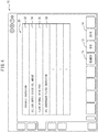
- the alarm window 20 is displayed in the main window 10 on the touch panel 122, whereby the operator can be notified that a malfunction has occurred in the machine tool 100.
- the alarm window 20 includes an area 22 for displaying that the window is an alarm window, an area 24 for displaying an alarm code, and an area 26 for displaying a malfunction item.
- Table 1 shows examples of malfunction items along with alarm codes. Though a single malfunction item is displayed in FIG. 3 , a plurality of malfunction items can be displayed.
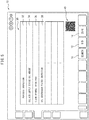
- FIG. 4 shows a periodic inspection window displayed on the touch panel 122 of the operation panel 120 as a message issued from the controller 130 of the machine tool 100 to the operator in order to prompt the operator to perform a periodic inspection.
- the periodic inspection is an item performed regardless of the uptime of the machine, such as a six-month inspection, a one-year inspection, or a two-year inspection, or an item performed in accordance with the uptime of the machine, such as a 160-hour inspection, a 500-hour inspection, or a 1000-hour inspection.
- Table 2 shows examples of periodic inspections.
- Table 2 Please inspect oil amount in oil/air supply device and replenish if low Please clean spindle taper part Please inspect oil filter of oil controller and clean if very dirty Please inspect oil flow of oil controller with the flow gauge Please inspect spindle-through line filter/suction filter Please inspect drum filter backwash amount Please inspect waste oil tank Please inspect amount of cutting oil and replenish if low Please inspect scale air pressure (for machines with scale) Please inspect main air pressure Please inspect amount of hydraulic oil of hydraulic device Please inspect pressure of hydraulic oil of hydraulic device Please adjust tension of outboard conveyor chain Please replace filter net of drum filter Please clean/replace line filter/suction filter Please inspect filter net of drum filter Please inspect coolant V seal Please clean coolant tank Please replace scale air oil mist filter (for machines with scale) Please replace main air filter Please clean air dryer condenser fins Please clean suction filter of hydraulic device Please clean fan cooler of hydraulic device Please replace hydraulic oil of hydraulic device Please replenish grease of Y-axis pantograph
- the controller 130 of the machine tool 100 simply counts the time which has elapsed since the prior inspection or since the performance of a maintenance operation associated with an inspection for items executed irrespective of uptime, and counts the elapsed time in accordance with the uptime of the machine regarding items executed in accordance with the uptime of the machine.
- the controller 130 displays the periodic inspection window 30 on the touch panel 122 of the operation panel 120.
- the periodic inspection window 30 includes an area 32 for displaying that the window is a periodic inspection window, and an area for displaying inspection items 34 to 38.
- the alarm window 20 or the periodic inspection window 30 is open, if the operator taps and selects one or a plurality of items from the malfunction item 34 of the inspection items 34 to 38 and taps the selection button 12, information related to the selected item(s) is displayed on the touch panel 122. When a plurality of items are selected, each of the plurality of items can be displayed in an individual tab.
- the information displayed on the touch panel 122 includes the name of the part in which the malfunction has occurred, the method for accessing the part in which the malfunction has occurred, an alarm resolution procedure, the name, serial number, and replacement method of a part to be replaced, the method for accessing the part for which periodic inspection should be performed, inspection methods such as visual inspection and verification of gauges, a maintenance procedure, and the name, serial number, and replacement method of a part to be replaced.
- a two-dimensional code 40 is displayed on the touch panel 122, as shown in FIG. 5 .
- the two-dimensional code 40 can include a URL and security information necessary for the mobile terminal to access the server on which the electronic manual is stored, as well as the above malfunction items and periodic inspection items.
- the mobile terminal 124 can be a commercially available smartphone or tablet, rather than a special device provided by the manufacturer of the machine tool 100.
- the alarm window 20 and the periodic inspection window 30 constitute machine-operated input parts.
- the alarm window 20 or the periodic inspection window 30 is displayed on the touch panel 122, by tapping the alarm window 20 or the periodic inspection window 30, information related to a resolution operation, such as an operation to resolve a malfunction, a method for accessing a part of the machine tool 100 for which an inspection operation should be performed, or a method for replacement of a part, or an inspection operation can be provided to the operator in a simple manner. Furthermore, by displaying the two-dimensional code 40 on the touch panel 122 and reading the two-dimensional code 40 with a smartphone or tablet, information related to the resolution operation or inspection operation is displayed on the smartphone or tablet, whereby information can be provided to the operator in a location separated from the touch panel 122.
- a resolution operation such as an operation to resolve a malfunction
- a method for accessing a part of the machine tool 100 for which an inspection operation should be performed or a method for replacement of a part, or an inspection operation
- information related to the resolution operation or inspection operation is displayed on the smartphone or tablet, whereby information can be provided to the operator in a
- the controller 130 of the machine tool 100 automatically displays the alarm window 20 and the periodic inspection window 30 on the touch panel 122.
- the operator can refer to the instruction manual as necessary.
- FIG. 6 shows a search window (top screen) with which the operator can search the electronic manual in such a case.
- the search window 50 is opened by tapping the search button 16 of the main window 10.
- the search window 50 includes a plurality of items corresponding to major items in the table of contents of a paper instruction manual.
- a search method selection window 54 with which the operator can select a search method from a plurality of search methods for searching the information related to the selected item opens.
- the search method selection window 54 includes a time search button 56 for searching by time, an appearance search button 58 for searching based on the appearance of the machine tool 100, a unit search button 60 for searching based on the units constituting the machine tool 100, an index button 62 for searching by keyword, and a movie search button 64 for searching video files explaining inspection methods and methods for replacing parts by means of a video.
- a similar search method selection window is opened when another item is selected.
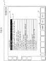
- the unit search window 70 is constituted by a list of the plurality of units constituting the machine tool 100, such as, for example, a spindle head, an automatic grease supply device, a pallet seating confirmation device, an ATC (automatic tool change) arm unit, a ring-type tool magazine, a spindle cooling oil temperature controller, an oil/air supply device, a hydraulic device, a pneumatic device, a chip processor/conveyor, a cutting fluid supply device/tank, and a splashguard.
- a spindle head such as, for example, a spindle head, an automatic grease supply device, a pallet seating confirmation device, an ATC (automatic tool change) arm unit, a ring-type tool magazine, a spindle cooling oil temperature controller, an oil/air supply device, a hydraulic device, a pneumatic device, a chip processor/conveyor, a cutting fluid supply device/tank, and a splashguard.
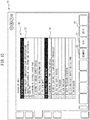
- the inspection item list of the spindle device includes lubrication of a spindle collet, inspection and cleaning of a tool shank and inspection of a tool pot, and cleaning of a spindle taper part.
- the touch panel 122 when the operator taps and selects one item or a plurality of items from the list window 72 of inspection items, and taps the selection button 12, information related to the selected item is displayed on the touch panel 122. When a plurality of items are selected, each of the plurality of items can be displayed in an individual tab.
- the information displayed on the touch panel 122 includes the name of the part in which the malfunction has occurred, the method for accessing the part in which the malfunction has occurred, the name, serial number, and replacement method of a part to be replaced, a method for accessing the part for which inspection should be performed, inspection methods such as visual inspection or confirmation of gauges, and the name, serial number, and replacement method of a part to be replaced.
- a two-dimensional code 40 which is similar to the two-dimensional code 40 described above is displayed on the touch panel 122.
- information can be displayed on the smartphone or tablet via the Internet 160.
- the list window of inspection items is not limited to a list window related to a single unit, as shown in FIG. 9 .
- the list windows 72, 74 related to a plurality of units, as shown in FIG. 10 , or alternatively, inspection item list windows related to all of the units displayed in the unit search window 70 may be opened.
- the operator can display the search window 50 on the touch panel 122, which enables the user to search and refer to the electronic manual as necessary.
- the search window 50 provides a plurality of search methods to the operator, and thus, in the present invention, the search window 50 constitutes an operator-operated input part.
Landscapes
- Engineering & Computer Science (AREA)
- Physics & Mathematics (AREA)
- General Physics & Mathematics (AREA)
- Theoretical Computer Science (AREA)
- Automation & Control Theory (AREA)
- Human Computer Interaction (AREA)
- General Engineering & Computer Science (AREA)
- Business, Economics & Management (AREA)
- Data Mining & Analysis (AREA)
- Databases & Information Systems (AREA)
- Mechanical Engineering (AREA)
- Manufacturing & Machinery (AREA)
- Human Resources & Organizations (AREA)
- Marketing (AREA)
- Operations Research (AREA)
- Quality & Reliability (AREA)
- Strategic Management (AREA)
- Tourism & Hospitality (AREA)
- General Business, Economics & Management (AREA)
- Entrepreneurship & Innovation (AREA)
- Economics (AREA)
- Numerical Control (AREA)
- Testing And Monitoring For Control Systems (AREA)
- Machine Tool Sensing Apparatuses (AREA)
- Management, Administration, Business Operations System, And Electronic Commerce (AREA)
Abstract
Description
- The present invention relates to an electronic manual for a machine tool for displaying information related to the operation, maintenance, or inspection of the machine tool, which is necessary for an operator, and a machine tool which can display the electronic manual.
- Since machine tools have a wide variety of specifications, mechanisms, functions, and target groups which are complicated, the instruction manuals therefor become enormous. A certain degree of skill is necessary in order to find necessary information in such an enormous instruction manual, and some users cannot obtain necessary information even while in possession of the instruction manual. Furthermore, machine tools are generally used for long periods of time, during which parts are improved on the manufacturer side and new products can be used for the lubricating oils and coolants thereof, which are consumables.
- Patent Literature 1 describes a machining device in which an input screen for inputting operation items is displayed on a display monitor of the machining device by means of the reading of identification codes recorded in an instruction manual with a reader connected to the controller of the machining device.
- [PTL 1] Japanese Unexamined Patent Publication (Kokai) No.
2014-24150 - In the machining device of Patent Literature 1, the time and effort of the inputting of maintenance information are reduced, and maintenance information can be accurately inputted in a short time. However, there are various types of maintenance, and the individual maintenance operations have different operation methods and time intervals at which the maintenance should be performed. Simply by simplifying the input operation as in Patent Literature 1, it remains unclear which operation item it is necessary to input in order to obtain appropriate maintenance information. Furthermore, in the case of not only maintenance and inspection but also malfunctions in the machining device, it is difficult to obtain information related to the operation to resolve the malfunction unless the correspondence between the malfunction and the operation item to be input to the display monitor is known.
- The present invention aims to solve such problems of the prior art by providing an electronic manual for a machine tool which can display information related to the operation, maintenance, and inspection of a machine tool, depending on a status, in a simple manner, and a machine tool which can display such an electronic manual.
- In order to achieve the above object, according to the present invention, there is provided an electronic manual for a machine tool for displaying information related to operation, maintenance, or inspection of the machine tool, which is necessary for an operator, the electronic manual comprising an operator-operated input part for inputting search conditions to search the electronic manual in accordance with intent of the operator in order to obtain necessary information, a machine-operated input part for selecting and inputting at least one item provided to the operator from the machine tool depending on a status of the machine tool, and a display part for displaying information related to operation, maintenance, or inspection of the machine tool corresponding to the input from the operator-operated input part or the machine-operated input part.
- Further, according to the present invention, there is provided a machine tool in which a workpiece and a tool are moved relative to each other to machine the workpiece, the machine tool comprising an operator-operated input part for inputting search conditions to search an electronic manual in accordance with intent of the operator in order to obtain necessary information, a machine-operated input part for selecting and inputting at least one item provided to the operator from the machine tool depending on a status of the machine tool, and a display part for displaying information related to operation, maintenance, or inspection of the machine tool corresponding to the input from the operator-operated input part or the machine-operated input part.
- According to the present invention, necessary information can be located in a simple manner even when the operator lacks skill in relation to the searching of the instruction manual. In particular, at least one item is provided from the machine tool depending on the status of the machine tool, and the operator can perform input by selecting the item, whereby information depending on the status of the machine tool can be reliably provided to the operator.
-
-
FIG. 1 is a side view of a machine tool according to an embodiment of the present invention. -
FIG. 2 is a block diagram showing an electronic manual which is connected to a server via the Internet. -
FIG. 3 is a view showing an example of an alarm window constituting a machine-operated input part displayed on a display part. -
FIG. 4 is a view showing an example of a periodic inspection window constituting the machine-operated input part displayed on the display part. -
FIG. 5 is a view of the periodic inspection window ofFIG. 3 , which shows a two-dimensional code. -
FIG. 6 is a view showing an example of a search window constituting an operator-operated input part displayed on the display part. -
FIG. 7 is a view showing an example of a search method selection window constituting the operator-operated input part displayed on the display part. -
FIG. 8 is a view showing an example of a unit search window constituting the operator-operated input part displayed on the display part. -
FIG. 9 is a view of the unit search window ofFIG. 7 in which one item is open. -
FIG. 10 is a view of the unit search window ofFIG. 7 in which two items are open. - Preferred embodiments of the present invention will be described below with reference to the attached drawings.
-
FIG. 1 shows an example of a machine tool to which the present invention is applied. InFIG. 1 , themachine tool 100 according to a preferred embodiment of the present invention constitutes a vertical machining center which is controlled by acontroller 130. Themachine tool 100 comprises abed 102 as a base fixed to the floor surface of a factory, a table 106 which is provided on an upper surface of a front portion (left side inFIG. 1 ) of thebed 102 so as to be moveable in the forwards and backwards directions or the Y-axis directions (the left and right directions inFIG. 1 ) and on which a workpiece W is fixed, anupright column 104 which is fixed on the upper surface of thebed 102 on the rear end side of the bed 102 (the right side inFIG. 1 ), anX-axis slider 108 which is provided on a front surface of thecolumn 104 so as to be movable in the left and right directions or the X-axis directions (the direction perpendicular to the sheet of the drawing ofFIG. 1 ), and aspindle head 110 which is attached on a front surface of theX-axis slider 108 so as to be movable in the upward and downward directions or the Z-axis directions and which rotatably supports aspindle 112. Atool 114 for machining the workpiece W fixed to the table 106 is mounted on the tip of thespindle 112. - The
machine tool 100 further comprises anoperation panel 120 with which an operator can operate themachine tool 100. Theoperation panel 120 comprises atouch panel 122 serving as the display part with which a desired portion can be selected by touching a screen. Theoperation panel 120 is connected to thecontroller 130 in which the electronic manual is stored. As shown inFIG. 2 , the electronic manual may be stored on aserver 162 and theoperation panel 120 may be connected to the server via the Internet 160. When connection is established via the Internet 160, individual machine tools have security information for accessing the server such as accounts, passwords or user authentication information. - In
FIGS. 3 to 10 , when the operator operates the electronic manual, amain window 10 for displaying information related to the machine tool is displayed on thetouch panel 122 of theoperation panel 120. Themain window 10 includes an area 18 for displaying analarm window 20, aperiodic inspection window 30, and asearch window 50, which are described later, aselection button 12, a two-dimensionalcode generation button 14, and asearch button 16. - The
controller 130 of themachine tool 100 continuously monitors each part of themachine tool 100 when themachine tool 100 is powered on and generates an alarm when a malfunction occurs in any of the parts of themachine tool 100. In particular, in the present embodiment, as shown inFIG. 2 , thealarm window 20 is displayed in themain window 10 on thetouch panel 122, whereby the operator can be notified that a malfunction has occurred in themachine tool 100. - Referring to
FIG. 3 , thealarm window 20 includes anarea 22 for displaying that the window is an alarm window, anarea 24 for displaying an alarm code, and anarea 26 for displaying a malfunction item. Table 1 shows examples of malfunction items along with alarm codes. Though a single malfunction item is displayed inFIG. 3 , a plurality of malfunction items can be displayed. -
Table 1 Alarm Code Item 60131 ATC Shutter Open Start Condition Abnormality (Operator Side Door Open) 60132 ATC Shutter Close Start Condition Abnormality (Operator Side Door Open) 60133 ATC Operation Start Condition Abnormality (Operator Side Door Open) 60134 Spindle Tool Clamp/Unclamp Operation Start Condition Abnormality (Operator Side Door Open) 60135 ATC Operation Start Condition Abnormality (Tool Magazine Manual Intervention) 60136 ATC Operation Condition Abnormality (TLS Door Open) 60137 ATC Operation Condition Abnormality (Spindle Tool Diameter/Length 0) 60138 ATC Operation Condition Abnormality (Spindle Tool Diameter 0) 70047 Spindle Command Abnormality 70048 Clamp Mechanism State Abnormality 70049 Spindle Start-Up Condition Abnormality 70050 Set Speed Abnormality 70051 Spindle Start-Up Condition Abnormality 70052 Spindle Start-Up Condition Abnormality 70053 Drawbar Probe Advancement Start Condition Abnormality 70054 Condition Abnormality During Drawbar Probe Advancement Operation 920033 Condition Abnormality During Pallet Change Operation (Time Limit Exceeded) 920034 Reconfirming Pallet Seating Confirmation 920035 Pallet Seating Confirmation Limit Switch Abnormality 920036 Pallet Seating Abnormality 920037 Pallet Seating Abnormality 920040 Condition Abnormality During Pallet Change Operation - Furthermore,
FIG. 4 shows a periodic inspection window displayed on thetouch panel 122 of theoperation panel 120 as a message issued from thecontroller 130 of themachine tool 100 to the operator in order to prompt the operator to perform a periodic inspection. The periodic inspection is an item performed regardless of the uptime of the machine, such as a six-month inspection, a one-year inspection, or a two-year inspection, or an item performed in accordance with the uptime of the machine, such as a 160-hour inspection, a 500-hour inspection, or a 1000-hour inspection. Table 2 shows examples of periodic inspections. -
Table 2 Please inspect oil amount in oil/air supply device and replenish if low Please clean spindle taper part Please inspect oil filter of oil controller and clean if very dirty Please inspect oil flow of oil controller with the flow gauge Please inspect spindle-through line filter/suction filter Please inspect drum filter backwash amount Please inspect waste oil tank Please inspect amount of cutting oil and replenish if low Please inspect scale air pressure (for machines with scale) Please inspect main air pressure Please inspect amount of hydraulic oil of hydraulic device Please inspect pressure of hydraulic oil of hydraulic device Please adjust tension of outboard conveyor chain Please replace filter net of drum filter Please clean/replace line filter/suction filter Please inspect filter net of drum filter Please inspect coolant V seal Please clean coolant tank Please replace scale air oil mist filter (for machines with scale) Please replace main air filter Please clean air dryer condenser fins Please clean suction filter of hydraulic device Please clean fan cooler of hydraulic device Please replace hydraulic oil of hydraulic device Please replenish grease of Y-axis pantograph - Regarding each inspection item, the
controller 130 of themachine tool 100, simply counts the time which has elapsed since the prior inspection or since the performance of a maintenance operation associated with an inspection for items executed irrespective of uptime, and counts the elapsed time in accordance with the uptime of the machine regarding items executed in accordance with the uptime of the machine. When the counted elapsed time reaches a value specified for an inspection item, thecontroller 130 displays theperiodic inspection window 30 on thetouch panel 122 of theoperation panel 120. Theperiodic inspection window 30 includes anarea 32 for displaying that the window is a periodic inspection window, and an area for displayinginspection items 34 to 38. - When the
alarm window 20 or theperiodic inspection window 30 is open, if the operator taps and selects one or a plurality of items from themalfunction item 34 of theinspection items 34 to 38 and taps theselection button 12, information related to the selected item(s) is displayed on thetouch panel 122. When a plurality of items are selected, each of the plurality of items can be displayed in an individual tab. The information displayed on thetouch panel 122 includes the name of the part in which the malfunction has occurred, the method for accessing the part in which the malfunction has occurred, an alarm resolution procedure, the name, serial number, and replacement method of a part to be replaced, the method for accessing the part for which periodic inspection should be performed, inspection methods such as visual inspection and verification of gauges, a maintenance procedure, and the name, serial number, and replacement method of a part to be replaced. - Furthermore, when the two-dimensional
code generation button 14 is tapped after item selection, a two-dimensional code 40 is displayed on thetouch panel 122, as shown inFIG. 5 . As shown inFIG. 2 , when the two-dimensional code 40 is read by amobile terminal 124, information can be displayed on themobile terminal 124 via the Internet 160. The two-dimensional code 40 can include a URL and security information necessary for the mobile terminal to access the server on which the electronic manual is stored, as well as the above malfunction items and periodic inspection items. Furthermore, themobile terminal 124 can be a commercially available smartphone or tablet, rather than a special device provided by the manufacturer of themachine tool 100. - Thus, when a malfunction occurs in a part of the
machine tool 100, or when the amount of time which has elapsed since the prior periodic inspection becomes a value specified for an inspection item, by displaying thealarm window 20 or theperiodic inspection window 30 on thetouch panel 122 of theoperation panel 120, the operator can be prompted by themachine tool 100 to perform an operation to resolve the malfunction or to perform the periodic inspection. In the present invention, thealarm window 20 and theperiodic inspection window 30 constitute machine-operated input parts. - When the
alarm window 20 or theperiodic inspection window 30 is displayed on thetouch panel 122, by tapping thealarm window 20 or theperiodic inspection window 30, information related to a resolution operation, such as an operation to resolve a malfunction, a method for accessing a part of themachine tool 100 for which an inspection operation should be performed, or a method for replacement of a part, or an inspection operation can be provided to the operator in a simple manner. Furthermore, by displaying the two-dimensional code 40 on thetouch panel 122 and reading the two-dimensional code 40 with a smartphone or tablet, information related to the resolution operation or inspection operation is displayed on the smartphone or tablet, whereby information can be provided to the operator in a location separated from thetouch panel 122. - In the embodiment described above, the
controller 130 of themachine tool 100 automatically displays thealarm window 20 and theperiodic inspection window 30 on thetouch panel 122. However, naturally, the operator can refer to the instruction manual as necessary.FIG. 6 shows a search window (top screen) with which the operator can search the electronic manual in such a case. - The
search window 50 is opened by tapping thesearch button 16 of themain window 10. Thesearch window 50 includes a plurality of items corresponding to major items in the table of contents of a paper instruction manual. When the operator taps and selects one item from the plurality of items, a searchmethod selection window 54 with which the operator can select a search method from a plurality of search methods for searching the information related to the selected item opens. - For example, when
preventative maintenance item 52 is tapped and selected, the searchmethod selection window 54 related to preventative maintenance of themachine tool 100 opens, as shown inFIG. 7 . The searchmethod selection window 54 includes atime search button 56 for searching by time, anappearance search button 58 for searching based on the appearance of themachine tool 100, aunit search button 60 for searching based on the units constituting themachine tool 100, anindex button 62 for searching by keyword, and amovie search button 64 for searching video files explaining inspection methods and methods for replacing parts by means of a video. A similar search method selection window is opened when another item is selected. - When the operator taps and selects, for example, the
unit search button 60 in the searchmethod selection window 54, theunit search window 70 ofFIG. 8 opens. Theunit search window 70 is constituted by a list of the plurality of units constituting themachine tool 100, such as, for example, a spindle head, an automatic grease supply device, a pallet seating confirmation device, an ATC (automatic tool change) arm unit, a ring-type tool magazine, a spindle cooling oil temperature controller, an oil/air supply device, a hydraulic device, a pneumatic device, a chip processor/conveyor, a cutting fluid supply device/tank, and a splashguard. - When the operator taps and selects, for example, the item related to the spindle device from the units displayed in the
unit search window 70, as shown inFIG. 9 , the item related to the spindle device opens, and alist window 72 of inspection items related to thespindle 112 of themachine tool 100 is displayed. InFIG. 9 , the inspection item list of the spindle device includes lubrication of a spindle collet, inspection and cleaning of a tool shank and inspection of a tool pot, and cleaning of a spindle taper part. - As described regarding the
alarm window 20 and theperiodic inspection window 30, when the operator taps and selects one item or a plurality of items from thelist window 72 of inspection items, and taps theselection button 12, information related to the selected item is displayed on thetouch panel 122. When a plurality of items are selected, each of the plurality of items can be displayed in an individual tab. The information displayed on thetouch panel 122 includes the name of the part in which the malfunction has occurred, the method for accessing the part in which the malfunction has occurred, the name, serial number, and replacement method of a part to be replaced, a method for accessing the part for which inspection should be performed, inspection methods such as visual inspection or confirmation of gauges, and the name, serial number, and replacement method of a part to be replaced. - Furthermore, when the two-dimensional
code generation button 14 is tapped after item selection, a two-dimensional code 40 which is similar to the two-dimensional code 40 described above is displayed on thetouch panel 122. By reading this two-dimensional code with a smartphone or tablet, information can be displayed on the smartphone or tablet via theInternet 160. - The list window of inspection items is not limited to a list window related to a single unit, as shown in
FIG. 9 . Thelist windows FIG. 10 , or alternatively, inspection item list windows related to all of the units displayed in theunit search window 70 may be opened. - Further, in the embodiment described above, the operator can display the
search window 50 on thetouch panel 122, which enables the user to search and refer to the electronic manual as necessary. Thesearch window 50 provides a plurality of search methods to the operator, and thus, in the present invention, thesearch window 50 constitutes an operator-operated input part. -
- 10
- Main Window
- 12
- Selection Button
- 14
- Two-Dimensional Code Generation Button
- 16
- Search Button
- 20
- Alarm Window
- 30
- Periodic Inspection Window
- 40
- Two-Dimensional Code
- 50
- Search Window (Top Screen)
- 52
- Preventative Maintenance Item
- 54
- Search Method Selection Window
- 56
- Time Search Button
- 58
- Appearance Search Button
- 60
- Unit Search Button
- 62
- Index Button
- 64
- Movie Search Button
- 70
- Unit Search Window
- 100
- Machine Tool
- 122
- Operation Panel
- 124
- Touch Panel
- 150
- Controller
Claims (4)
- An electronic manual for a machine tool for displaying information related to operation, maintenance, or inspection of the machine tool, which is necessary for an operator, the electronic manual comprising:an operator-operated input part for inputting search conditions to search the electronic manual in accordance with intent of the operator in order to obtain necessary information,a machine-operated input part for selecting and inputting at least one item provided to the operator from the machine tool depending on a status of the machine tool, anda display part for displaying information related to operation, maintenance, or inspection of the machine tool corresponding to the input from the operator-operated input part or the machine-operated input part.
- The electronic manual for a machine tool according to claim 1, wherein the electronic manual is stored in a controller of the machine tool, an Internet-connected server, or a mobile terminal.
- The electronic manual for a machine tool according to claim 1, wherein a two-dimensional code related to information related to operation, maintenance, or inspection of the machine tool displayed on the display part is further displayed on the display part, and
the mobile terminal is connected to a server via the Internet as a result of reading of the two-dimensional code by the mobile terminal, and the information related to operation, maintenance, or inspection of the machine tool displayed on the display part is displayed on the mobile terminal. - A machine tool in which a workpiece and a tool are moved relative to each other to machine the workpiece, the machine tool comprising:an operator-operated input part for inputting search conditions to search an electronic manual in accordance with intent of the operator in order to obtain necessary information,a machine-operated input part for selecting and inputting at least one item provided to the operator from the machine tool depending on a status of the machine tool, anda display part for displaying information related to operation, maintenance, or inspection of the machine tool corresponding to the input from the operator-operated input part or the machine-operated input part.
Applications Claiming Priority (1)
| Application Number | Priority Date | Filing Date | Title |
|---|---|---|---|
| PCT/JP2016/076701 WO2018047313A1 (en) | 2016-09-09 | 2016-09-09 | Electronic manual for machine tool, and machine tool |
Publications (3)
| Publication Number | Publication Date |
|---|---|
| EP3511119A1 true EP3511119A1 (en) | 2019-07-17 |
| EP3511119A4 EP3511119A4 (en) | 2020-04-22 |
| EP3511119B1 EP3511119B1 (en) | 2024-10-23 |
Family
ID=61562040
Family Applications (1)
| Application Number | Title | Priority Date | Filing Date |
|---|---|---|---|
| EP16915731.0A Active EP3511119B1 (en) | 2016-09-09 | 2016-09-09 | Machine tool |
Country Status (6)
| Country | Link |
|---|---|
| US (1) | US11009850B2 (en) |
| EP (1) | EP3511119B1 (en) |
| JP (1) | JP6807932B2 (en) |
| CN (1) | CN109689291B (en) |
| TW (1) | TWI636851B (en) |
| WO (1) | WO2018047313A1 (en) |
Families Citing this family (11)
| Publication number | Priority date | Publication date | Assignee | Title |
|---|---|---|---|---|
| US10871763B2 (en) * | 2017-10-27 | 2020-12-22 | Dr. Johannes Heidenhain Gmbh | Manually operated machine tool display |
| JP7441602B2 (en) * | 2018-09-27 | 2024-03-01 | 株式会社ジェイテクト | Machining support system and cutting equipment |
| JP2020052938A (en) * | 2018-09-28 | 2020-04-02 | 光洋電子工業株式会社 | Operation panel management system |
| JP7132166B2 (en) * | 2019-04-04 | 2022-09-06 | ファナック株式会社 | Numerical controller and numerical control system |
| WO2021177238A1 (en) * | 2020-03-06 | 2021-09-10 | ファナック株式会社 | Control device |
| DE112021003654T5 (en) | 2020-07-08 | 2023-04-27 | Fanuc Corporation | Apparatus for generating a setting code, an industrial machine, a method for generating a setting code, and a program for generating a setting code |
| USD1116875S1 (en) * | 2021-06-23 | 2026-03-10 | Trumpf Gmbh + Co. Kg | Machine tool operating device |
| CN116494128A (en) * | 2022-01-19 | 2023-07-28 | 众程科技股份有限公司 | Grinder platform with detection system |
| JP7798650B2 (en) * | 2022-03-29 | 2026-01-14 | 株式会社ディスコ | processing equipment |
| JPWO2024089739A1 (en) * | 2022-10-24 | 2024-05-02 | ||
| DE102024104383A1 (en) * | 2024-02-16 | 2025-08-21 | Homag Bohrsysteme Gmbh | Processing machine and clamping device with electronic information display |
Family Cites Families (28)
| Publication number | Priority date | Publication date | Assignee | Title |
|---|---|---|---|---|
| US4991077A (en) * | 1986-07-29 | 1991-02-05 | Fuji Electric Co., Ltd. | Programmable operator's console |
| US5189624A (en) * | 1989-09-29 | 1993-02-23 | General Electric Company | Intelligent machining workstation operating logic |
| JP2839786B2 (en) * | 1992-04-30 | 1998-12-16 | 三菱電機株式会社 | Plant operation support device |
| US5848426A (en) * | 1993-03-05 | 1998-12-08 | Metanetics Corporation | Automatic data translation between different business systems |
| JPH07152411A (en) * | 1993-11-29 | 1995-06-16 | Okuma Mach Works Ltd | Numerical controller having alarm notifying function |
| US5513264A (en) * | 1994-04-05 | 1996-04-30 | Metanetics Corporation | Visually interactive encoding and decoding of dataforms |
| US6961712B1 (en) * | 1996-10-25 | 2005-11-01 | Ipf, Inc. | Consumer product information request (CPIR) enabling servlets and web-based consumer product information catalogs employing the same |
| JP3374579B2 (en) * | 1995-03-20 | 2003-02-04 | 三菱電機株式会社 | Processing condition determination device |
| JP4044169B2 (en) * | 1997-02-26 | 2008-02-06 | 株式会社アマダ | Display method of information setting screen along process flow and multi-window type NC device having the function |
| US6138056A (en) * | 1998-03-02 | 2000-10-24 | Therwood Corporation | System and method for maintenance and repair of CNC machines |
| JP2002197216A (en) * | 2000-12-27 | 2002-07-12 | Mitsubishi Electric Corp | Information management apparatus, information management method, and recording medium on which information management program is recorded |
| JP2002232584A (en) * | 2001-01-30 | 2002-08-16 | Higashi Nihon Medicom Kk | Article information system utilizing mobile terminal |
| EP1403863A3 (en) * | 2002-05-31 | 2006-09-27 | Heidelberger Druckmaschinen Aktiengesellschaft | Apparatus and method for retrieving and displaying information |
| DE10322684A1 (en) * | 2003-05-20 | 2004-12-16 | Siemens Ag | Method for processing a version change of a data set comprising medical therapy information |
| JP2009129227A (en) | 2007-11-26 | 2009-06-11 | Toshiba Mach Co Ltd | Control device, machine tool, and display method |
| EP2515190B1 (en) * | 2009-12-15 | 2021-02-03 | Yamazaki Mazak Corporation | Numerical control machine tool |
| JP2011160305A (en) | 2010-02-03 | 2011-08-18 | Canon Inc | Electronic apparatus |
| JP2014024150A (en) | 2012-07-26 | 2014-02-06 | Disco Abrasive Syst Ltd | Machining apparatus and instruction manual for the same |
| DE112012007259T5 (en) * | 2012-12-26 | 2015-09-24 | Mitsubishi Electric Corporation | Electronics Manual Browse Leaflet and System |
| DE102013005769A1 (en) * | 2013-04-05 | 2014-10-09 | Robert Bosch Gmbh | Machine, computer program product for a device for displaying data and method for monitoring the status of a machine |
| EP2837979B1 (en) * | 2013-08-13 | 2021-11-24 | ABB Schweiz AG | A method, apparatus and a computer program product for configuring a frequency converter |
| JP6079561B2 (en) * | 2013-10-29 | 2017-02-15 | 株式会社安川電機 | Display control system, display control method, document extraction device, portable information terminal, program, and information storage medium |
| BR112016028380A2 (en) * | 2014-06-03 | 2017-08-22 | Pb Innovate Pty Ltd | information retrieval system and method |
| JP2016099800A (en) | 2014-11-21 | 2016-05-30 | カシオ計算機株式会社 | Electronic apparatus and display system |
| US10192329B2 (en) * | 2014-09-19 | 2019-01-29 | Casio Computer Co., Ltd. | Electronic device which displays and outputs function formula data, data output method, and computer readable medium |
| JP6386871B2 (en) * | 2014-10-22 | 2018-09-05 | オークマ株式会社 | Numerical controller for machine tools |
| CN205271415U (en) * | 2015-12-15 | 2016-06-01 | 天津市天森智能设备有限公司 | Digit control machine tool erects version operating panel |
| DE102017105377A1 (en) * | 2016-03-17 | 2017-09-21 | Jtekt Corporation | Control console for machine tools and machine tool management system |
-
2016
- 2016-09-09 WO PCT/JP2016/076701 patent/WO2018047313A1/en not_active Ceased
- 2016-09-09 EP EP16915731.0A patent/EP3511119B1/en active Active
- 2016-09-09 JP JP2018537965A patent/JP6807932B2/en active Active
- 2016-09-09 CN CN201680089116.4A patent/CN109689291B/en active Active
- 2016-09-09 US US16/331,870 patent/US11009850B2/en active Active
- 2016-10-21 TW TW105134100A patent/TWI636851B/en active
Also Published As
| Publication number | Publication date |
|---|---|
| TWI636851B (en) | 2018-10-01 |
| TW201811494A (en) | 2018-04-01 |
| JPWO2018047313A1 (en) | 2019-04-11 |
| JP6807932B2 (en) | 2021-01-06 |
| CN109689291B (en) | 2021-08-24 |
| US20190377324A1 (en) | 2019-12-12 |
| US11009850B2 (en) | 2021-05-18 |
| CN109689291A (en) | 2019-04-26 |
| WO2018047313A1 (en) | 2018-03-15 |
| EP3511119A4 (en) | 2020-04-22 |
| EP3511119B1 (en) | 2024-10-23 |
Similar Documents
| Publication | Publication Date | Title |
|---|---|---|
| EP3511119B1 (en) | Machine tool | |
| CN110023858B (en) | Machine tool management system and machine tool management method | |
| US11544651B2 (en) | Electronic manual system for machine tool | |
| JP6114828B2 (en) | Tool management system | |
| CN202780640U (en) | Tool changer of machine tool | |
| CN102854842A (en) | Machine control program creating device | |
| JP6789300B2 (en) | Work measurement method | |
| JP2018041136A (en) | Processing device and actuation method therefor | |
| JP6819080B2 (en) | Processing history search system | |
| JP7167607B2 (en) | Machine Tools | |
| JP2018063668A (en) | Mold history display apparatus and mold press apparatus | |
| TWI627014B (en) | Electronic manual for working machinery | |
| JP6113244B2 (en) | Machine tool failure diagnosis method and machine tool control apparatus | |
| WO2022244070A1 (en) | Operation status display device and computer-readable storage medium | |
| JP6105016B1 (en) | Machine tool controller | |
| CN119233876A (en) | Machine tool |
Legal Events
| Date | Code | Title | Description |
|---|---|---|---|
| STAA | Information on the status of an ep patent application or granted ep patent |
Free format text: STATUS: THE INTERNATIONAL PUBLICATION HAS BEEN MADE |
|
| PUAI | Public reference made under article 153(3) epc to a published international application that has entered the european phase |
Free format text: ORIGINAL CODE: 0009012 |
|
| STAA | Information on the status of an ep patent application or granted ep patent |
Free format text: STATUS: REQUEST FOR EXAMINATION WAS MADE |
|
| 17P | Request for examination filed |
Effective date: 20190405 |
|
| AK | Designated contracting states |
Kind code of ref document: A1 Designated state(s): AL AT BE BG CH CY CZ DE DK EE ES FI FR GB GR HR HU IE IS IT LI LT LU LV MC MK MT NL NO PL PT RO RS SE SI SK SM TR |
|
| AX | Request for extension of the european patent |
Extension state: BA ME |
|
| DAV | Request for validation of the european patent (deleted) | ||
| DAX | Request for extension of the european patent (deleted) | ||
| REG | Reference to a national code |
Ref legal event code: R079 Ipc: G05B0019409000 Ref country code: DE Ref legal event code: R079 Ref document number: 602016089986 Country of ref document: DE Free format text: PREVIOUS MAIN CLASS: B23Q0017000000 Ipc: G05B0019409000 |
|
| A4 | Supplementary search report drawn up and despatched |
Effective date: 20200319 |
|
| RIC1 | Information provided on ipc code assigned before grant |
Ipc: G05B 23/02 20060101ALI20200313BHEP Ipc: G06F 16/00 20190101ALI20200313BHEP Ipc: G05B 19/409 20060101AFI20200313BHEP Ipc: B23Q 17/00 20060101ALI20200313BHEP |
|
| STAA | Information on the status of an ep patent application or granted ep patent |
Free format text: STATUS: EXAMINATION IS IN PROGRESS |
|
| 17Q | First examination report despatched |
Effective date: 20211213 |
|
| GRAP | Despatch of communication of intention to grant a patent |
Free format text: ORIGINAL CODE: EPIDOSNIGR1 |
|
| STAA | Information on the status of an ep patent application or granted ep patent |
Free format text: STATUS: GRANT OF PATENT IS INTENDED |
|
| INTG | Intention to grant announced |
Effective date: 20240605 |
|
| GRAS | Grant fee paid |
Free format text: ORIGINAL CODE: EPIDOSNIGR3 |
|
| P01 | Opt-out of the competence of the unified patent court (upc) registered |
Free format text: CASE NUMBER: APP_44961/2024 Effective date: 20240802 |
|
| GRAA | (expected) grant |
Free format text: ORIGINAL CODE: 0009210 |
|
| STAA | Information on the status of an ep patent application or granted ep patent |
Free format text: STATUS: THE PATENT HAS BEEN GRANTED |
|
| AK | Designated contracting states |
Kind code of ref document: B1 Designated state(s): AL AT BE BG CH CY CZ DE DK EE ES FI FR GB GR HR HU IE IS IT LI LT LU LV MC MK MT NL NO PL PT RO RS SE SI SK SM TR |
|
| REG | Reference to a national code |
Ref country code: GB Ref legal event code: FG4D |
|
| REG | Reference to a national code |
Ref country code: CH Ref legal event code: EP |
|
| REG | Reference to a national code |
Ref country code: DE Ref legal event code: R096 Ref document number: 602016089986 Country of ref document: DE |
|
| REG | Reference to a national code |
Ref country code: IE Ref legal event code: FG4D |
|
| REG | Reference to a national code |
Ref country code: LT Ref legal event code: MG9D |
|
| REG | Reference to a national code |
Ref country code: NL Ref legal event code: MP Effective date: 20241023 |
|
| REG | Reference to a national code |
Ref country code: AT Ref legal event code: MK05 Ref document number: 1735336 Country of ref document: AT Kind code of ref document: T Effective date: 20241023 |
|
| PG25 | Lapsed in a contracting state [announced via postgrant information from national office to epo] |
Ref country code: NL Free format text: LAPSE BECAUSE OF FAILURE TO SUBMIT A TRANSLATION OF THE DESCRIPTION OR TO PAY THE FEE WITHIN THE PRESCRIBED TIME-LIMIT Effective date: 20241023 |
|
| PG25 | Lapsed in a contracting state [announced via postgrant information from national office to epo] |
Ref country code: NL Free format text: LAPSE BECAUSE OF FAILURE TO SUBMIT A TRANSLATION OF THE DESCRIPTION OR TO PAY THE FEE WITHIN THE PRESCRIBED TIME-LIMIT Effective date: 20241023 |
|
| PG25 | Lapsed in a contracting state [announced via postgrant information from national office to epo] |
Ref country code: IS Free format text: LAPSE BECAUSE OF FAILURE TO SUBMIT A TRANSLATION OF THE DESCRIPTION OR TO PAY THE FEE WITHIN THE PRESCRIBED TIME-LIMIT Effective date: 20250223 Ref country code: HR Free format text: LAPSE BECAUSE OF FAILURE TO SUBMIT A TRANSLATION OF THE DESCRIPTION OR TO PAY THE FEE WITHIN THE PRESCRIBED TIME-LIMIT Effective date: 20241023 Ref country code: PT Free format text: LAPSE BECAUSE OF FAILURE TO SUBMIT A TRANSLATION OF THE DESCRIPTION OR TO PAY THE FEE WITHIN THE PRESCRIBED TIME-LIMIT Effective date: 20250224 |
|
| PG25 | Lapsed in a contracting state [announced via postgrant information from national office to epo] |
Ref country code: FI Free format text: LAPSE BECAUSE OF FAILURE TO SUBMIT A TRANSLATION OF THE DESCRIPTION OR TO PAY THE FEE WITHIN THE PRESCRIBED TIME-LIMIT Effective date: 20241023 |
|
| PG25 | Lapsed in a contracting state [announced via postgrant information from national office to epo] |
Ref country code: BG Free format text: LAPSE BECAUSE OF FAILURE TO SUBMIT A TRANSLATION OF THE DESCRIPTION OR TO PAY THE FEE WITHIN THE PRESCRIBED TIME-LIMIT Effective date: 20241023 |
|
| PG25 | Lapsed in a contracting state [announced via postgrant information from national office to epo] |
Ref country code: ES Free format text: LAPSE BECAUSE OF FAILURE TO SUBMIT A TRANSLATION OF THE DESCRIPTION OR TO PAY THE FEE WITHIN THE PRESCRIBED TIME-LIMIT Effective date: 20241023 |
|
| PG25 | Lapsed in a contracting state [announced via postgrant information from national office to epo] |
Ref country code: NO Free format text: LAPSE BECAUSE OF FAILURE TO SUBMIT A TRANSLATION OF THE DESCRIPTION OR TO PAY THE FEE WITHIN THE PRESCRIBED TIME-LIMIT Effective date: 20250123 |
|
| PG25 | Lapsed in a contracting state [announced via postgrant information from national office to epo] |
Ref country code: GR Free format text: LAPSE BECAUSE OF FAILURE TO SUBMIT A TRANSLATION OF THE DESCRIPTION OR TO PAY THE FEE WITHIN THE PRESCRIBED TIME-LIMIT Effective date: 20250124 Ref country code: LV Free format text: LAPSE BECAUSE OF FAILURE TO SUBMIT A TRANSLATION OF THE DESCRIPTION OR TO PAY THE FEE WITHIN THE PRESCRIBED TIME-LIMIT Effective date: 20241023 Ref country code: AT Free format text: LAPSE BECAUSE OF FAILURE TO SUBMIT A TRANSLATION OF THE DESCRIPTION OR TO PAY THE FEE WITHIN THE PRESCRIBED TIME-LIMIT Effective date: 20241023 |
|
| PG25 | Lapsed in a contracting state [announced via postgrant information from national office to epo] |
Ref country code: PL Free format text: LAPSE BECAUSE OF FAILURE TO SUBMIT A TRANSLATION OF THE DESCRIPTION OR TO PAY THE FEE WITHIN THE PRESCRIBED TIME-LIMIT Effective date: 20241023 |
|
| PG25 | Lapsed in a contracting state [announced via postgrant information from national office to epo] |
Ref country code: RS Free format text: LAPSE BECAUSE OF FAILURE TO SUBMIT A TRANSLATION OF THE DESCRIPTION OR TO PAY THE FEE WITHIN THE PRESCRIBED TIME-LIMIT Effective date: 20250123 |
|
| PG25 | Lapsed in a contracting state [announced via postgrant information from national office to epo] |
Ref country code: SM Free format text: LAPSE BECAUSE OF FAILURE TO SUBMIT A TRANSLATION OF THE DESCRIPTION OR TO PAY THE FEE WITHIN THE PRESCRIBED TIME-LIMIT Effective date: 20241023 |
|
| PG25 | Lapsed in a contracting state [announced via postgrant information from national office to epo] |
Ref country code: DK Free format text: LAPSE BECAUSE OF FAILURE TO SUBMIT A TRANSLATION OF THE DESCRIPTION OR TO PAY THE FEE WITHIN THE PRESCRIBED TIME-LIMIT Effective date: 20241023 |
|
| PG25 | Lapsed in a contracting state [announced via postgrant information from national office to epo] |
Ref country code: EE Free format text: LAPSE BECAUSE OF FAILURE TO SUBMIT A TRANSLATION OF THE DESCRIPTION OR TO PAY THE FEE WITHIN THE PRESCRIBED TIME-LIMIT Effective date: 20241023 |
|
| PG25 | Lapsed in a contracting state [announced via postgrant information from national office to epo] |
Ref country code: RO Free format text: LAPSE BECAUSE OF FAILURE TO SUBMIT A TRANSLATION OF THE DESCRIPTION OR TO PAY THE FEE WITHIN THE PRESCRIBED TIME-LIMIT Effective date: 20241023 |
|
| REG | Reference to a national code |
Ref country code: DE Ref legal event code: R097 Ref document number: 602016089986 Country of ref document: DE |
|
| PG25 | Lapsed in a contracting state [announced via postgrant information from national office to epo] |
Ref country code: SK Free format text: LAPSE BECAUSE OF FAILURE TO SUBMIT A TRANSLATION OF THE DESCRIPTION OR TO PAY THE FEE WITHIN THE PRESCRIBED TIME-LIMIT Effective date: 20241023 |
|
| PG25 | Lapsed in a contracting state [announced via postgrant information from national office to epo] |
Ref country code: CZ Free format text: LAPSE BECAUSE OF FAILURE TO SUBMIT A TRANSLATION OF THE DESCRIPTION OR TO PAY THE FEE WITHIN THE PRESCRIBED TIME-LIMIT Effective date: 20241023 |
|
| PLBE | No opposition filed within time limit |
Free format text: ORIGINAL CODE: 0009261 |
|
| STAA | Information on the status of an ep patent application or granted ep patent |
Free format text: STATUS: NO OPPOSITION FILED WITHIN TIME LIMIT |
|
| PG25 | Lapsed in a contracting state [announced via postgrant information from national office to epo] |
Ref country code: SE Free format text: LAPSE BECAUSE OF FAILURE TO SUBMIT A TRANSLATION OF THE DESCRIPTION OR TO PAY THE FEE WITHIN THE PRESCRIBED TIME-LIMIT Effective date: 20241023 |
|
| 26N | No opposition filed |
Effective date: 20250724 |
|
| PGFP | Annual fee paid to national office [announced via postgrant information from national office to epo] |
Ref country code: DE Payment date: 20250730 Year of fee payment: 10 |
|
| PGFP | Annual fee paid to national office [announced via postgrant information from national office to epo] |
Ref country code: IT Payment date: 20250825 Year of fee payment: 10 |
|
| PGFP | Annual fee paid to national office [announced via postgrant information from national office to epo] |
Ref country code: GB Payment date: 20250731 Year of fee payment: 10 |
|
| PGFP | Annual fee paid to national office [announced via postgrant information from national office to epo] |
Ref country code: FR Payment date: 20250808 Year of fee payment: 10 |
|
| REG | Reference to a national code |
Ref country code: CH Ref legal event code: H13 Free format text: ST27 STATUS EVENT CODE: U-0-0-H10-H13 (AS PROVIDED BY THE NATIONAL OFFICE) Effective date: 20260504 |