EP3511115A1 - Machine tool - Google Patents
Machine tool Download PDFInfo
- Publication number
- EP3511115A1 EP3511115A1 EP16915725.2A EP16915725A EP3511115A1 EP 3511115 A1 EP3511115 A1 EP 3511115A1 EP 16915725 A EP16915725 A EP 16915725A EP 3511115 A1 EP3511115 A1 EP 3511115A1
- Authority
- EP
- European Patent Office
- Prior art keywords
- machine body
- peripheral device
- coolant
- device frame
- machine tool
- Prior art date
- Legal status (The legal status is an assumption and is not a legal conclusion. Google has not performed a legal analysis and makes no representation as to the accuracy of the status listed.)
- Withdrawn
Links
Images



Classifications
-
- B—PERFORMING OPERATIONS; TRANSPORTING
- B23—MACHINE TOOLS; METAL-WORKING NOT OTHERWISE PROVIDED FOR
- B23Q—DETAILS, COMPONENTS, OR ACCESSORIES FOR MACHINE TOOLS, e.g. ARRANGEMENTS FOR COPYING OR CONTROLLING; MACHINE TOOLS IN GENERAL CHARACTERISED BY THE CONSTRUCTION OF PARTICULAR DETAILS OR COMPONENTS; COMBINATIONS OR ASSOCIATIONS OF METAL-WORKING MACHINES, NOT DIRECTED TO A PARTICULAR RESULT
- B23Q11/00—Accessories fitted to machine tools for keeping tools or parts of the machine in good working condition or for cooling work; Safety devices specially combined with or arranged in, or specially adapted for use in connection with, machine tools
- B23Q11/12—Arrangements for cooling or lubricating parts of the machine
- B23Q11/126—Arrangements for cooling or lubricating parts of the machine for cooling only
-
- B—PERFORMING OPERATIONS; TRANSPORTING
- B23—MACHINE TOOLS; METAL-WORKING NOT OTHERWISE PROVIDED FOR
- B23Q—DETAILS, COMPONENTS, OR ACCESSORIES FOR MACHINE TOOLS, e.g. ARRANGEMENTS FOR COPYING OR CONTROLLING; MACHINE TOOLS IN GENERAL CHARACTERISED BY THE CONSTRUCTION OF PARTICULAR DETAILS OR COMPONENTS; COMBINATIONS OR ASSOCIATIONS OF METAL-WORKING MACHINES, NOT DIRECTED TO A PARTICULAR RESULT
- B23Q1/00—Members which are comprised in the general build-up of a form of machine, particularly relatively large fixed members
- B23Q1/0009—Energy-transferring means or control lines for movable machine parts; Control panels or boxes; Control parts
- B23Q1/0045—Control panels or boxes
-
- B—PERFORMING OPERATIONS; TRANSPORTING
- B23—MACHINE TOOLS; METAL-WORKING NOT OTHERWISE PROVIDED FOR
- B23Q—DETAILS, COMPONENTS, OR ACCESSORIES FOR MACHINE TOOLS, e.g. ARRANGEMENTS FOR COPYING OR CONTROLLING; MACHINE TOOLS IN GENERAL CHARACTERISED BY THE CONSTRUCTION OF PARTICULAR DETAILS OR COMPONENTS; COMBINATIONS OR ASSOCIATIONS OF METAL-WORKING MACHINES, NOT DIRECTED TO A PARTICULAR RESULT
- B23Q11/00—Accessories fitted to machine tools for keeping tools or parts of the machine in good working condition or for cooling work; Safety devices specially combined with or arranged in, or specially adapted for use in connection with, machine tools
- B23Q11/0003—Arrangements for preventing undesired thermal effects on tools or parts of the machine
-
- B—PERFORMING OPERATIONS; TRANSPORTING
- B23—MACHINE TOOLS; METAL-WORKING NOT OTHERWISE PROVIDED FOR
- B23Q—DETAILS, COMPONENTS, OR ACCESSORIES FOR MACHINE TOOLS, e.g. ARRANGEMENTS FOR COPYING OR CONTROLLING; MACHINE TOOLS IN GENERAL CHARACTERISED BY THE CONSTRUCTION OF PARTICULAR DETAILS OR COMPONENTS; COMBINATIONS OR ASSOCIATIONS OF METAL-WORKING MACHINES, NOT DIRECTED TO A PARTICULAR RESULT
- B23Q11/00—Accessories fitted to machine tools for keeping tools or parts of the machine in good working condition or for cooling work; Safety devices specially combined with or arranged in, or specially adapted for use in connection with, machine tools
- B23Q11/0042—Devices for removing chips
- B23Q11/0067—Devices for removing chips chip containers located under a machine or under a chip conveyor
-
- B—PERFORMING OPERATIONS; TRANSPORTING
- B23—MACHINE TOOLS; METAL-WORKING NOT OTHERWISE PROVIDED FOR
- B23Q—DETAILS, COMPONENTS, OR ACCESSORIES FOR MACHINE TOOLS, e.g. ARRANGEMENTS FOR COPYING OR CONTROLLING; MACHINE TOOLS IN GENERAL CHARACTERISED BY THE CONSTRUCTION OF PARTICULAR DETAILS OR COMPONENTS; COMBINATIONS OR ASSOCIATIONS OF METAL-WORKING MACHINES, NOT DIRECTED TO A PARTICULAR RESULT
- B23Q11/00—Accessories fitted to machine tools for keeping tools or parts of the machine in good working condition or for cooling work; Safety devices specially combined with or arranged in, or specially adapted for use in connection with, machine tools
- B23Q11/10—Arrangements for cooling or lubricating tools or work
- B23Q11/1069—Filtration systems specially adapted for cutting liquids
Definitions
- the present invention relates to a machine tool having a machine body, a control panel, a coolant filtration and supply device, and peripheral devices.
- a machine tool includes, in addition to the machine body, a control panel fastened to the machine body by bolts and a coolant tank having casters enabling it to be moved close to and moved away from the machine body.
- a machine tool further usually includes peripheral devices such as a spindle lubricating oil temperature control device, an air dryer for cleaning pressurized air source air and removing moisture from it, and a guide surface lubricating oil feed device.
- peripheral devices such as a spindle lubricating oil temperature control device, an air dryer for cleaning pressurized air source air and removing moisture from it, and a guide surface lubricating oil feed device.
- a coolant tank usually includes a filter for removing chips from the coolant. For this reason, regular maintenance is required for cleaning, replacing, and otherwise maintaining the filter.
- the direction of movement when pulling out the coolant tank from a fixed position adjoining the machine body has been limited to a predetermined single direction in order to avoid interference between the coolant tank and the support columns of the peripheral device frame. Due to this, deterioration of the work efficiency in movement of the coolant tank, that is, the work efficiency when the coolant tank is moved close to and away from the machine body, had been caused.
- the present invention is made in consideration of the above situation and has as its object to provide a machine tool facilitating the work of moving a coolant tank close to and away from a machine body in routine maintenance.
- a machine tool supplying coolant to a processing part and processing a workpiece by a tool
- the machine tool comprising a machine body having a mechanism making the tool and the workpiece move relative to each other, a control panel housing a control device controlling operation of the machine body, a peripheral device frame adjoining one side surface of the machine body and with a substantially rectangular shape in a top view for mounting a peripheral device, wherein at least two corners of one end of the rectangular shape are supported, a corner of the other end of the rectangular shape at a side close to the machine body is supported from below, and a corner of the other end of the rectangular shape at a side far from the machine body is not supported from below, and a coolant filtration and supply device having a coolant tank arranged below the peripheral device frame so as to hold the coolant discharged from the machine body, the coolant filtration and supply device being set to be able to approach and move away from the machine body.
- the peripheral device frame does not have a support column at the corner of the other end at the side far from the machine body, so it becomes possible to increase the degree of freedom in the direction of movement of the coolant filtration and supply device.
- the direction of movement can be made any direction within a 90 degree range of angle. As a result, it becomes possible to facilitate the work for moving the coolant filtration and supply device to and away from the machine body.
- the machine tool 100 of this embodiment is configured as a vertical machining center comprising a machine body 10, control panel 20, coolant filtration and supply device 30, peripheral device 60, and peripheral device frame 40 carrying the peripheral device 60.
- the machine body 10, control panel 20, coolant filtration and supply device 30, and peripheral device 60 are known general ones, so the explanations will be kept simple.
- FIG. 1 and FIG. 2 as the peripheral device 60, an air dryer for cleaning pressurized air source air and removing moisture from it is illustrated.
- the peripheral device frame 40 usually carries a plurality of peripheral devices in addition to an air dryer such as a not shown, for example, spindle lubricating oil temperature control device and guide surface lubricating oil feed device.
- the peripheral devices 60 may include compressors or pumps or other rotary devices.
- FIG. 1 is a perspective view of the machine tool 100 from which splash guards and other covers of the machine tool body 10 are removed for facilitating understanding and as seen from the back surface side.
- FIG. 2 is a perspective view of the machine tool 100 in the state further removing the coolant filtration and supply device 30 and as again seen from the back surface side.
- the machine body 10 is provided with a bed 11 placed on a floor surface, a column 12 placed on and fastened to the bed 11, a saddle, not shown in FIG. 1 and FIG. 2 , which is designed to be able to move across the front side of the column 12 in the X-axis direction by an X-axis motor 13, a spindle head designed to be able to move across the front side of the saddle in the Z-axis direction with respect to the saddle, a table designed to be able to move over the bed 11 in the Y-axis direction, a Y-axis motor 14 for table feed use shown in FIG. 2 , etc.
- a cable guide 15 is arranged above the machine body 10.
- the machine body 10 is also provided with a groove, that is, trough (not shown), receiving coolant and chips dropping down from the processing part and flowing to the back of the machine.
- the trough is set on a U-shaped groove 16 formed on the bed 11 shown in FIG. 2 . Its front end part sticks out to the back from the back surface of the machine body 10 so that coolant and chips drop down from the front end part to the coolant tank 32 of the coolant filtration and supply device 30 below it.
- the machine body 10 is also provided with a back surface splash guard 17 attached to the back surface and prevents the coolant and chips in the processing chamber from splashing backward.
- the control panel 20, in the present embodiment, is placed standing independently from the machine body 10 at the right side in FIG. 1 at the back surface side of the machine body 10 and is provided with a box shaped housing 21 set on the floor surface. At the outside of the back surface of the housing 21 of the control panel 20, an amp housing box 22 of the feed motor is attached.
- the coolant filtration and supply device 30 comprises a filtration and supply device housing 31, coolant tank 32, coolant feed pump 33, liftup chip conveyor 34, chip guide 35, control panel 36 of the coolant filtration and supply device 30, and not shown filter.
- the coolant filtration and supply device 30 is set adjoining the back surface of the machine body 10 so that the housing 31 abuts against the back surface of the machine body 10.
- the filtration and supply device housing 31 is formed in a substantially rectangular shape from a top view and is formed in a step shape in a side view from the back surface side of the machine tool 100, the coolant tank 32 is formed mainly at the part of the left side of FIG. 1 , and chips are separated at the low part at the right side.
- the coolant receiving port of the coolant tank 32 for receiving the coolant and chips flowing down from the trough (not shown) is not shown, but is provided at the low part at the right side of the filtration and supply device housing 31 at a side close to the machine body 10.
- the coolant after filtering of the chips is recirculated by the coolant feed pump 33 to the machine body 10.
- the separated chips are lifted up by the liftup chip conveyor 34 and dropped down from the chip drop opening 35a at the bottom end of the chip guide 35.
- a chip collecting container is placed by the user under the chip drop opening 35a.
- casters 37 for movement use and stoppers 38 for preventing movement are attached.
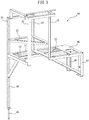
- the peripheral device frame 40 is formed as a frame structure such as shown in the independent perspective view of FIG. 3 .
- the peripheral device frame 40 has a main shelf part 45 on which the peripheral device 60 can be placed in the middle of the top-bottom direction.
- the main shelf part 45 has a substantially rectangular contour from a top view despite having a recess at the left side of FIG. 3 .
- a first column member 41 to a fourth column member 44 are provided. These are connected to each other at their top end parts by a plurality of members extending horizontally.
- an auxiliary shelf part 57 is formed inside the space formed by the first column member 41 to the fourth column member 44 as well.
- One of the peripheral devices 60 as shown in FIG. 1 , an air dryer, is placed on the auxiliary shelf part 57.
- the peripheral device frame 40 has a substantially rectangular contour, as will be understood from FIG. 3 .
- the peripheral device frame 40 has a first support column 46 and a second support column 47 at the two corners of the rectangular shape of the main shelf part 45 in the front-back direction of one end adjoining the control panel 20.
- the first support column 46 and second support column 47 in the present embodiment, are bolted to the back surface of the housing 21 of the control panel 20 and do not reach the floor surface.
- the peripheral device frame 40 has a third support column 48 supporting from the bottom the corner of the main shelf part 45 at the other end at the opposite side of the above end at the side close to the machine body 10.
- the third support column 48 in the present embodiment, is formed continuously integrally with the third column member 43.
- the third support column 48 is supported by contacting the floor surface with a length adjuster 49 provided at its front end part. In this way, the peripheral device frame 40 is not supported from the bottom at the corner at the other end at a side far from machine body 10.
- the peripheral device frame 40 is placed standing together with the control panel 20 independent from the machine body 10 at a position adjoining the machine body 10.
- the peripheral device frame 40 has step shaped mounting members 52 such as shown in FIG. 4 for connecting it to the machine body 10.
- the peripheral device frame 40 is engaged by the member 51 extending to the left and right at the machine body 10 side of the main shelf part 45 at two locations to a structural member 18 of the machine body 10 through the mounting members 52 to be able to move in a predetermined range.
- the mounting members 52 are firmly fastened to the member 51 of the main shelf part 45 of the peripheral device frame 40 by fastening bolts 53, but is engaged with the structural member 18 of the machine body 10 by the loose fitting members 54 to be able to move within a predetermined range.
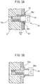
- Each loose fitting member 54 is comprised of a bolt 55 and a flanged bush 56 through which the bolt 55 is inserted.
- the flanged bush 56 has a cylindrical shaped bush part 56b and a flange 56a formed integrally with one end of the same.
- the bush part 56b of the flanged bush 56 is inserted into a mounting hole provided at the mounting member 52 and the bolt 55 is screwed into a screw hole 18a provided at the structural member 18.
- the dimensions of the inside diameter of the mounting hole are determined with respect to the outside diameter of the bush part 56b so that a gap Gr is formed in the radial direction.
- the length of the bush part 56b is determined with respect to the thickness of the mounting member 52 so that a gap Gy is formed in the longitudinal axis direction of the bolt 55, that is, the Y-axis direction.
- the mounting members 52 firmly fastened to the peripheral device frame 40 are engaged by the loose fitting members 54 so as to form a gap Gy with respect to the machine body 10 and form a gap Gr with respect to the flanged bush 56 but so as not to be separated by over the gap Gy.
- propagation of vibration generated by a pump or compressor or other rotary device of the peripheral device 60 placed on the peripheral device frame 40 to the machine body 10 is reduced, and transmission of heat generated by the peripheral device 60 to the machine body 10 is also reduced.
- These vibration and heat reduce the processing precision of the machining operation performed by the machine body 10, so the detrimental effect on the processing precision of the machine body 10 is also reduced due to the reduction in propagation or transmission of vibration and heat.
- first and second support columns 46, 47 are fastened to the housing of the relatively large control panel 20, so even if the corner of the other end of the main shelf part 45 at the side far from the machine body 10 is not supported from below by a support column, the peripheral device frame 40 can stand independently integral with the control panel 20.
- the loose fitting members 54 are provided for preventing the peripheral device frame 40 from gradually moving and separating from the machine body 10 together with the control panel 20 due to the vibration of the peripheral device 60. Further, the loose fitting members 54 are useful for preventing the peripheral device frame 40 and the control panel 20 from falling over at the time of an earthquake.
- the peripheral device frame 40 does not have a support column at the corner of the other end of the main shelf part 45 at the side far from the machine body 10, so a high degree of freedom is given to the direction of movement in the case of pulling the coolant filtration and supply device 30 away from the machine body 10 at the time of maintenance of the same or in the case of returning it to the fixed position shown in FIG. 1 after maintenance.
- the direction of movement specifically may be directions shown by the intersecting arrow Ax and arrow Ay in FIG. 1 and directions of any angles between these arrows.
- the degree of freedom of the coolant filtration and supply device 30 in the direction of movement at the time of maintenance is raised, so the conditions for setting the machine tool 100 relative to other devices which will be arranged around the machine tool 100 and relative to the distance from the wall surface of the factory and the direction of the wall surface are eased and the work efficiency of movement of the coolant filtration and supply device 30 is also raised.
- the peripheral device frame 40 is usually engaged with the machine body 10 so as to enable movement in the range of the gap formed by the loose fitting members 54, but the peripheral device frame 40 may also be firmly fastened to the machine body 10 for example at the time of transport of the machine tool 100.
- FIG. 5B it is possible to firmly join the peripheral device frame 40 to the machine body 10 by attaching the flanged bushes 56 to the bolts 55 in the reverse direction front to back to the case of FIG. 5A .
- the first and second support columns at one end of the rectangular shape of the main shelf part of the peripheral device frame may also be supported at the floor surface in the same way as the third support column 48 while not being fastened to the control panel 20. In this case, it is not possible to support by support columns the turning moment, generated in almost all cases in accordance with a position of the center of gravity of the plurality of peripheral devices 60 as a whole placed on the peripheral device frame as seen from a plan view, acting so as to separate the peripheral device frame from the machine body 10.
Landscapes
- Engineering & Computer Science (AREA)
- Mechanical Engineering (AREA)
- Machine Tool Units (AREA)
- Auxiliary Devices For Machine Tools (AREA)
Abstract
Description
- The present invention relates to a machine tool having a machine body, a control panel, a coolant filtration and supply device, and peripheral devices.
- A machine tool, as described in for example PTL 1, includes, in addition to the machine body, a control panel fastened to the machine body by bolts and a coolant tank having casters enabling it to be moved close to and moved away from the machine body. A machine tool further usually includes peripheral devices such as a spindle lubricating oil temperature control device, an air dryer for cleaning pressurized air source air and removing moisture from it, and a guide surface lubricating oil feed device. These peripheral devices often used to be installed together at a frame for peripheral device considering space saving, convenience at the time of movement of the machine tool, etc. The frame for peripheral device is placed standing on the floor near the coolant tank and is fastened to the machine body by bolts etc.
- [PTL 1] Japanese Patent No.
4815896 - A coolant tank usually includes a filter for removing chips from the coolant. For this reason, regular maintenance is required for cleaning, replacing, and otherwise maintaining the filter. In the past, for maintenance, the direction of movement when pulling out the coolant tank from a fixed position adjoining the machine body has been limited to a predetermined single direction in order to avoid interference between the coolant tank and the support columns of the peripheral device frame. Due to this, deterioration of the work efficiency in movement of the coolant tank, that is, the work efficiency when the coolant tank is moved close to and away from the machine body, had been caused.
- The present invention is made in consideration of the above situation and has as its object to provide a machine tool facilitating the work of moving a coolant tank close to and away from a machine body in routine maintenance.
- To achieve the above-mentioned object, according to the present invention, there is provided a machine tool supplying coolant to a processing part and processing a workpiece by a tool, the machine tool comprising a machine body having a mechanism making the tool and the workpiece move relative to each other, a control panel housing a control device controlling operation of the machine body, a peripheral device frame adjoining one side surface of the machine body and with a substantially rectangular shape in a top view for mounting a peripheral device, wherein at least two corners of one end of the rectangular shape are supported, a corner of the other end of the rectangular shape at a side close to the machine body is supported from below, and a corner of the other end of the rectangular shape at a side far from the machine body is not supported from below, and a coolant filtration and supply device having a coolant tank arranged below the peripheral device frame so as to hold the coolant discharged from the machine body, the coolant filtration and supply device being set to be able to approach and move away from the machine body.
- According to this, the peripheral device frame does not have a support column at the corner of the other end at the side far from the machine body, so it becomes possible to increase the degree of freedom in the direction of movement of the coolant filtration and supply device. The direction of movement can be made any direction within a 90 degree range of angle. As a result, it becomes possible to facilitate the work for moving the coolant filtration and supply device to and away from the machine body.
-
-
FIG. 1 is a perspective view of a machine tool according to an embodiment of the present invention as seen from a back surface side. -
FIG. 2 is a perspective view of the machine tool from which a coolant filtration and supply device is removed as seen from a back surface side. -
FIG. 3 is a perspective view of a peripheral device frame. -
FIG. 4 is a perspective view showing a mounting member of the peripheral device frame and loose fitting members attached to the same. -
FIG. 5A is a schematic sectional view of a part to which a loose fitting member is attached showing the state where the peripheral device frame is engaged with the machine body by the loose fitting member. -
FIG. 5B is a schematic sectional view of a part to which the loose fitting member is attached showing the state where the peripheral device frame is firmly joined with the machine body using the loose fitting member. - Below, referring to
FIG. 1 to FIG. 5B , amachine tool 100 according to one embodiment of the present invention will be explained. Themachine tool 100 of this embodiment is configured as a vertical machining center comprising amachine body 10,control panel 20, coolant filtration andsupply device 30,peripheral device 60, andperipheral device frame 40 carrying theperipheral device 60. Note that, themachine body 10,control panel 20, coolant filtration andsupply device 30, andperipheral device 60 are known general ones, so the explanations will be kept simple. - In
FIG. 1 andFIG. 2 , as theperipheral device 60, an air dryer for cleaning pressurized air source air and removing moisture from it is illustrated. InFIG. 1 andFIG. 2 , in this way, a singleperipheral device 60 is drawn as a representative device, but theperipheral device frame 40 usually carries a plurality of peripheral devices in addition to an air dryer such as a not shown, for example, spindle lubricating oil temperature control device and guide surface lubricating oil feed device. Theperipheral devices 60 may include compressors or pumps or other rotary devices.FIG. 1 is a perspective view of themachine tool 100 from which splash guards and other covers of themachine tool body 10 are removed for facilitating understanding and as seen from the back surface side.FIG. 2 is a perspective view of themachine tool 100 in the state further removing the coolant filtration andsupply device 30 and as again seen from the back surface side. - The
machine body 10 is provided with a bed 11 placed on a floor surface, acolumn 12 placed on and fastened to the bed 11, a saddle, not shown inFIG. 1 andFIG. 2 , which is designed to be able to move across the front side of thecolumn 12 in the X-axis direction by anX-axis motor 13, a spindle head designed to be able to move across the front side of the saddle in the Z-axis direction with respect to the saddle, a table designed to be able to move over the bed 11 in the Y-axis direction, a Y-axis motor 14 for table feed use shown inFIG. 2 , etc. Above themachine body 10, acable guide 15 is arranged. Themachine body 10 is also provided with a groove, that is, trough (not shown), receiving coolant and chips dropping down from the processing part and flowing to the back of the machine. The trough is set on aU-shaped groove 16 formed on the bed 11 shown inFIG. 2 . Its front end part sticks out to the back from the back surface of themachine body 10 so that coolant and chips drop down from the front end part to thecoolant tank 32 of the coolant filtration andsupply device 30 below it. Further, themachine body 10 is also provided with a backsurface splash guard 17 attached to the back surface and prevents the coolant and chips in the processing chamber from splashing backward. - The
control panel 20, in the present embodiment, is placed standing independently from themachine body 10 at the right side inFIG. 1 at the back surface side of themachine body 10 and is provided with a box shapedhousing 21 set on the floor surface. At the outside of the back surface of thehousing 21 of thecontrol panel 20, anamp housing box 22 of the feed motor is attached. - The coolant filtration and
supply device 30 comprises a filtration andsupply device housing 31,coolant tank 32,coolant feed pump 33,liftup chip conveyor 34,chip guide 35,control panel 36 of the coolant filtration andsupply device 30, and not shown filter. The coolant filtration andsupply device 30 is set adjoining the back surface of themachine body 10 so that thehousing 31 abuts against the back surface of themachine body 10. The filtration andsupply device housing 31 is formed in a substantially rectangular shape from a top view and is formed in a step shape in a side view from the back surface side of themachine tool 100, thecoolant tank 32 is formed mainly at the part of the left side ofFIG. 1 , and chips are separated at the low part at the right side. The coolant receiving port of thecoolant tank 32 for receiving the coolant and chips flowing down from the trough (not shown) is not shown, but is provided at the low part at the right side of the filtration andsupply device housing 31 at a side close to themachine body 10. The coolant after filtering of the chips is recirculated by thecoolant feed pump 33 to themachine body 10. The separated chips are lifted up by theliftup chip conveyor 34 and dropped down from the chip drop opening 35a at the bottom end of thechip guide 35. Note that, while not shown, usually a chip collecting container is placed by the user under the chip drop opening 35a. Further, at the four corners of the bottom surface of the filtration andsupply device housing 31,casters 37 for movement use and stoppers 38 for preventing movement are attached. - The
peripheral device frame 40 is formed as a frame structure such as shown in the independent perspective view ofFIG. 3 . Theperipheral device frame 40 has amain shelf part 45 on which theperipheral device 60 can be placed in the middle of the top-bottom direction. Themain shelf part 45 has a substantially rectangular contour from a top view despite having a recess at the left side ofFIG. 3 . From the region at the left side of themain shelf part 45, afirst column member 41 to afourth column member 44 are provided. These are connected to each other at their top end parts by a plurality of members extending horizontally. Inside the space formed by thefirst column member 41 to thefourth column member 44 as well, anauxiliary shelf part 57 is formed. One of theperipheral devices 60, as shown inFIG. 1 , an air dryer, is placed on theauxiliary shelf part 57. Further, in a plan view of theperipheral device frame 40 as a whole as well, theperipheral device frame 40 has a substantially rectangular contour, as will be understood fromFIG. 3 . - The
peripheral device frame 40 has afirst support column 46 and asecond support column 47 at the two corners of the rectangular shape of themain shelf part 45 in the front-back direction of one end adjoining thecontrol panel 20. Thefirst support column 46 andsecond support column 47, in the present embodiment, are bolted to the back surface of thehousing 21 of thecontrol panel 20 and do not reach the floor surface. Theperipheral device frame 40 has athird support column 48 supporting from the bottom the corner of themain shelf part 45 at the other end at the opposite side of the above end at the side close to themachine body 10. Thethird support column 48, in the present embodiment, is formed continuously integrally with thethird column member 43. Thethird support column 48 is supported by contacting the floor surface with alength adjuster 49 provided at its front end part. In this way, theperipheral device frame 40 is not supported from the bottom at the corner at the other end at a side far frommachine body 10. Theperipheral device frame 40 is placed standing together with thecontrol panel 20 independent from themachine body 10 at a position adjoining themachine body 10. - The
peripheral device frame 40 has step shaped mountingmembers 52 such as shown inFIG. 4 for connecting it to themachine body 10. Theperipheral device frame 40 is engaged by themember 51 extending to the left and right at themachine body 10 side of themain shelf part 45 at two locations to astructural member 18 of themachine body 10 through the mountingmembers 52 to be able to move in a predetermined range. The mountingmembers 52 are firmly fastened to themember 51 of themain shelf part 45 of theperipheral device frame 40 by fasteningbolts 53, but is engaged with thestructural member 18 of themachine body 10 by the loosefitting members 54 to be able to move within a predetermined range. - Each loose
fitting member 54 is comprised of abolt 55 and aflanged bush 56 through which thebolt 55 is inserted. Theflanged bush 56 has a cylindrical shapedbush part 56b and aflange 56a formed integrally with one end of the same. As shown inFIG. 5A , usually, thebush part 56b of theflanged bush 56 is inserted into a mounting hole provided at the mountingmember 52 and thebolt 55 is screwed into ascrew hole 18a provided at thestructural member 18. At this time, the dimensions of the inside diameter of the mounting hole are determined with respect to the outside diameter of thebush part 56b so that a gap Gr is formed in the radial direction. Further, the length of thebush part 56b is determined with respect to the thickness of the mountingmember 52 so that a gap Gy is formed in the longitudinal axis direction of thebolt 55, that is, the Y-axis direction. - In this way, the mounting
members 52 firmly fastened to theperipheral device frame 40 are engaged by the loosefitting members 54 so as to form a gap Gy with respect to themachine body 10 and form a gap Gr with respect to theflanged bush 56 but so as not to be separated by over the gap Gy. For this reason, propagation of vibration generated by a pump or compressor or other rotary device of theperipheral device 60 placed on theperipheral device frame 40 to themachine body 10 is reduced, and transmission of heat generated by theperipheral device 60 to themachine body 10 is also reduced. These vibration and heat reduce the processing precision of the machining operation performed by themachine body 10, so the detrimental effect on the processing precision of themachine body 10 is also reduced due to the reduction in propagation or transmission of vibration and heat. - Further, the first and
second support columns large control panel 20, so even if the corner of the other end of themain shelf part 45 at the side far from themachine body 10 is not supported from below by a support column, theperipheral device frame 40 can stand independently integral with thecontrol panel 20. However, the loosefitting members 54 are provided for preventing theperipheral device frame 40 from gradually moving and separating from themachine body 10 together with thecontrol panel 20 due to the vibration of theperipheral device 60. Further, the loosefitting members 54 are useful for preventing theperipheral device frame 40 and thecontrol panel 20 from falling over at the time of an earthquake. - As explained above, in the
machine tool 100 according to the present embodiment, theperipheral device frame 40 does not have a support column at the corner of the other end of themain shelf part 45 at the side far from themachine body 10, so a high degree of freedom is given to the direction of movement in the case of pulling the coolant filtration andsupply device 30 away from themachine body 10 at the time of maintenance of the same or in the case of returning it to the fixed position shown inFIG. 1 after maintenance. The direction of movement specifically may be directions shown by the intersecting arrow Ax and arrow Ay inFIG. 1 and directions of any angles between these arrows. According to this embodiment, the degree of freedom of the coolant filtration andsupply device 30 in the direction of movement at the time of maintenance is raised, so the conditions for setting themachine tool 100 relative to other devices which will be arranged around themachine tool 100 and relative to the distance from the wall surface of the factory and the direction of the wall surface are eased and the work efficiency of movement of the coolant filtration andsupply device 30 is also raised. - In the present embodiment, the
peripheral device frame 40 is usually engaged with themachine body 10 so as to enable movement in the range of the gap formed by the loosefitting members 54, but theperipheral device frame 40 may also be firmly fastened to themachine body 10 for example at the time of transport of themachine tool 100. As shown inFIG. 5B , it is possible to firmly join theperipheral device frame 40 to themachine body 10 by attaching theflanged bushes 56 to thebolts 55 in the reverse direction front to back to the case ofFIG. 5A . By attaching theflanged bushes 56 to thebolts 55 as shown inFIG. 5A at the time of installation after the end of transport, as explained above, it is possible to engage theperipheral device frame 40 with themachine body 10 to be able to move within a predetermined range. In this Description, the state of the loosefitting member 54 shown inFIG. 5A will be called the "loose fitting engaged state having a gap", while the state of the loosefitting member 54 shown inFIG. 5B will be called the "joined state eliminating the gap". - The first and second support columns at one end of the rectangular shape of the main shelf part of the peripheral device frame may also be supported at the floor surface in the same way as the
third support column 48 while not being fastened to thecontrol panel 20. In this case, it is not possible to support by support columns the turning moment, generated in almost all cases in accordance with a position of the center of gravity of the plurality ofperipheral devices 60 as a whole placed on the peripheral device frame as seen from a plan view, acting so as to separate the peripheral device frame from themachine body 10. However, even if such a turning moment is generated, this is supported by the loosefitting members 54, so it is also possible to realize the peripheral device frame which has the first to third support columns supported at the floor surface but does not have a support column at the corner of the other end of the main shelf part at the side far from themachine body 10. -
- 10 machine body
- 20 control panel
- 30 coolant filtration and supply device
- 32 coolant tank
- 40 peripheral device frame
- 45 main shelf part
- 46 first support column
- 47 second support column
- 48 third support column
- 52 mounting member
- 54 loose fitting member
- 55 bolt
- 56 flanged bush
- 60 peripheral device
- 100 machine tool
Claims (4)
- A machine tool supplying coolant to a processing part and processing a workpiece by a tool, the machine tool comprising:a machine body having a mechanism making the tool and the workpiece move relative to each other;a control panel housing a control device controlling operation of the machine body;a peripheral device frame adjoining one side surface of the machine body and with a substantially rectangular shape from a top view for mounting a peripheral device, wherein at least two corners of one end of the rectangular shape are supported, a corner of the other end of the rectangular shape at a side close to the machine body is supported from below, and a corner of the other end of the rectangular shape at a side far from the machine body is not supported from below; anda coolant filtration and supply device having a coolant tank arranged below the peripheral device frame so as to hold the coolant discharged from the machine body, the coolant filtration and supply device being set to be able to move close to and away from the machine body.
- The machine tool according to claim 1, further comprising a loose fitting member making the peripheral device frame engage with the machine body so that the peripheral device frame will not separate from the machine body by over a predetermined distance.
- The machine tool according to claim 1 or 2, whereinthe control panel is set adjoining the machine body, andthe two corners of the one end of the rectangular shape of the peripheral device frame are fastened to a housing of the control panel.
- The machine tool according to claim 2, whereinthe loose fitting member comprises a bolt and a flanged bush through which the bolt is inserted, andthe loose fitting member can take a joined state with no gap and a loose fitting engaged state with a gap at a time of transport and time of installation of the machine tool by attaching the flanged bush facing backward and forward.
Applications Claiming Priority (1)
| Application Number | Priority Date | Filing Date | Title |
|---|---|---|---|
| PCT/JP2016/076684 WO2018047307A1 (en) | 2016-09-09 | 2016-09-09 | Machine tool |
Publications (2)
| Publication Number | Publication Date |
|---|---|
| EP3511115A1 true EP3511115A1 (en) | 2019-07-17 |
| EP3511115A4 EP3511115A4 (en) | 2020-05-06 |
Family
ID=61561764
Family Applications (1)
| Application Number | Title | Priority Date | Filing Date |
|---|---|---|---|
| EP16915725.2A Withdrawn EP3511115A4 (en) | 2016-09-09 | 2016-09-09 | Machine tool |
Country Status (6)
| Country | Link |
|---|---|
| US (1) | US20190358760A1 (en) |
| EP (1) | EP3511115A4 (en) |
| JP (1) | JP6602484B2 (en) |
| CN (1) | CN109661291A (en) |
| TW (1) | TWI628033B (en) |
| WO (1) | WO2018047307A1 (en) |
Families Citing this family (1)
| Publication number | Priority date | Publication date | Assignee | Title |
|---|---|---|---|---|
| JP7574713B2 (en) * | 2021-03-29 | 2024-10-29 | ブラザー工業株式会社 | Machine Tools |
Family Cites Families (33)
| Publication number | Priority date | Publication date | Assignee | Title |
|---|---|---|---|---|
| US2482302A (en) * | 1946-04-25 | 1949-09-20 | Thompson Grinder Co | Filtering system |
| US3042211A (en) * | 1959-08-27 | 1962-07-03 | Hoffman Internat Corp | Filter for liquids containing magnetic sludge |
| CH510488A (en) * | 1969-05-20 | 1971-07-31 | Dubied & Cie Sa E | Lathe |
| US3702740A (en) * | 1970-04-13 | 1972-11-14 | Rockwell Mfg Co | Drill press with coolant means |
| JPS60157162U (en) * | 1984-03-28 | 1985-10-19 | セイコ−精機株式会社 | small grinder |
| JPH0643002B2 (en) * | 1986-02-17 | 1994-06-08 | 株式会社森精機製作所 | NC lathe |
| JPH055305U (en) * | 1991-04-08 | 1993-01-26 | セイコー精機株式会社 | Spindle moving type automatic lathe |
| DE4212175A1 (en) * | 1992-04-10 | 1993-10-14 | Emag Masch Vertriebs Serv Gmbh | Machining center composed of assemblies |
| JP3781649B2 (en) * | 2001-09-10 | 2006-05-31 | 株式会社牧野フライス製作所 | Automatic tool changer |
| JP3952161B2 (en) * | 2002-03-26 | 2007-08-01 | ブラザー工業株式会社 | Machine Tools |
| JP2004243452A (en) * | 2003-02-13 | 2004-09-02 | Topcon Corp | Lens grinding system |
| JP4522162B2 (en) * | 2003-11-07 | 2010-08-11 | 株式会社トプコン | Grinding water treatment equipment for lens grinding equipment |
| DE102004044098A1 (en) * | 2004-09-08 | 2006-03-23 | Chiron-Werke Gmbh & Co. Kg | Machine tool with a machine foot |
| US20060153653A1 (en) * | 2005-01-12 | 2006-07-13 | Chen-Sheng Lu | Structural steel beam assemblies for a machining device |
| TWM275050U (en) * | 2005-02-03 | 2005-09-11 | Li-Jie Lin | Improved machine tool structure |
| JP4815896B2 (en) * | 2005-06-29 | 2011-11-16 | ブラザー工業株式会社 | Machine Tools |
| DE202005014852U1 (en) * | 2005-09-14 | 2005-11-10 | Otto Häfner GmbH & Co KG | Processing unit in particular for metal work-pieces, arranged in linear position with individual areas located beside each other |
| WO2008023768A1 (en) * | 2006-08-23 | 2008-02-28 | System-Keiso Co., Ltd. | Machining device with filter device |
| TWM324561U (en) * | 2007-06-22 | 2008-01-01 | Geng-Jang Jang | Processing machine containing detachable tool holder |
| EP2255921B1 (en) * | 2008-02-29 | 2012-09-19 | Horkos Corp | Machine tool |
| CN100584500C (en) * | 2008-04-03 | 2010-01-27 | 常州工学院 | CNC electrolytic mechanical compound processing machine tool |
| CN101844315B (en) * | 2009-03-27 | 2012-11-07 | 兄弟工业株式会社 | Tool cleaning device |
| DE102009054043A1 (en) * | 2009-11-20 | 2011-05-26 | Mag Ias Gmbh | Generic machine tool for processing metal workpieces, has spindle to mount tool arranged on x-slide and moved by utilizing motor in y-direction on x-slide, and workpiece positioning unit for workpiece to be processed positioned in space |
| DE102011080457A1 (en) * | 2011-08-04 | 2013-02-07 | Mag Ias Gmbh | Machine tool for machining work pieces, has machine frame and tool spindle, which is provided for supporting tool provided for machining work pieces, where tool spindle is arranged at machine frame |
| DE112011105739B4 (en) * | 2011-10-14 | 2023-07-13 | Mitsubishi Electric Corporation | machine tool |
| CN202428196U (en) * | 2011-12-19 | 2012-09-12 | 青岛辉腾机械设备有限公司 | Gantry moving type machine tool |
| US9539688B2 (en) * | 2012-06-25 | 2017-01-10 | Makino Milling Machine Co., Ltd. | Machine tool |
| EP2777871B1 (en) * | 2013-03-12 | 2015-05-27 | Maschinenfabrik Berthold Hermle AG | Machining centre with a machine housing |
| DE102013005908A1 (en) * | 2013-04-05 | 2014-10-09 | Martin Göckel | Multifunctional processing machine |
| EP3015201B1 (en) * | 2013-06-28 | 2018-10-24 | Makino Milling Machine Co., Ltd. | Main spindle device for machine tool and machine tool |
| CN204867160U (en) * | 2015-07-09 | 2015-12-16 | 东莞市智感机械电子科技有限公司 | Be applied to feedway of wire winding core wire mascerating machine |
| CN205254508U (en) * | 2015-12-08 | 2016-05-25 | 苏州博众精工科技有限公司 | Screw feed mechanism |
| CN105500102A (en) * | 2016-01-13 | 2016-04-20 | 成都佳美嘉科技有限公司 | Chip removal device of numerical control machine tool |
-
2016
- 2016-09-09 JP JP2018537959A patent/JP6602484B2/en active Active
- 2016-09-09 EP EP16915725.2A patent/EP3511115A4/en not_active Withdrawn
- 2016-09-09 WO PCT/JP2016/076684 patent/WO2018047307A1/en not_active Ceased
- 2016-09-09 US US16/331,334 patent/US20190358760A1/en not_active Abandoned
- 2016-09-09 CN CN201680088974.7A patent/CN109661291A/en active Pending
- 2016-10-21 TW TW105134093A patent/TWI628033B/en active
Also Published As
| Publication number | Publication date |
|---|---|
| US20190358760A1 (en) | 2019-11-28 |
| JP6602484B2 (en) | 2019-11-06 |
| WO2018047307A1 (en) | 2018-03-15 |
| EP3511115A4 (en) | 2020-05-06 |
| JPWO2018047307A1 (en) | 2019-04-25 |
| TWI628033B (en) | 2018-07-01 |
| CN109661291A (en) | 2019-04-19 |
| TW201811489A (en) | 2018-04-01 |
Similar Documents
| Publication | Publication Date | Title |
|---|---|---|
| US10960506B2 (en) | Machine tool | |
| US9457445B2 (en) | Machine tool with cover adapted for discharge of chips | |
| US9694459B2 (en) | Chip discharge device of machine tool | |
| US7018147B2 (en) | Arrangement structure of machine tool | |
| EP3476775B1 (en) | Silent spiral conveyor | |
| US20190358760A1 (en) | Machine tool | |
| JP2026042087A (en) | Coolant treatment device and machine tool | |
| US7044696B2 (en) | Chip discharging device for machine tool | |
| JP2015193066A (en) | Chip discharge device of machine tool | |
| JP6178613B2 (en) | Oil / water separator | |
| KR102402627B1 (en) | Work piece cutting system and work piece welding fixing system | |
| CN105364491B (en) | A five-axis CNC machining center | |
| KR102912168B1 (en) | Microchip processing equipment of machine tools | |
| KR101165926B1 (en) | broach machine | |
| KR102454644B1 (en) | Cover apparatus of vertical type machine tool | |
| KR102221977B1 (en) | A processing device that is easy to fix the processing target with an asymmetric structure | |
| US11493169B2 (en) | Support structure | |
| US20210162555A1 (en) | Support structure | |
| CN209754669U (en) | Vertical machine tool | |
| JP2009136973A (en) | Machine tool coolant tank | |
| CN209665361U (en) | A kind of slide unit mould group | |
| US7037052B2 (en) | Spindle unit of machine tool | |
| JP7339475B1 (en) | Cover member and machine tool | |
| JP7864235B2 (en) | Coolant treatment device | |
| CN215688617U (en) | Artificial tooth engraving and milling machine |
Legal Events
| Date | Code | Title | Description |
|---|---|---|---|
| STAA | Information on the status of an ep patent application or granted ep patent |
Free format text: STATUS: THE INTERNATIONAL PUBLICATION HAS BEEN MADE |
|
| PUAI | Public reference made under article 153(3) epc to a published international application that has entered the european phase |
Free format text: ORIGINAL CODE: 0009012 |
|
| STAA | Information on the status of an ep patent application or granted ep patent |
Free format text: STATUS: REQUEST FOR EXAMINATION WAS MADE |
|
| 17P | Request for examination filed |
Effective date: 20190228 |
|
| AK | Designated contracting states |
Kind code of ref document: A1 Designated state(s): AL AT BE BG CH CY CZ DE DK EE ES FI FR GB GR HR HU IE IS IT LI LT LU LV MC MK MT NL NO PL PT RO RS SE SI SK SM TR |
|
| AX | Request for extension of the european patent |
Extension state: BA ME |
|
| DAV | Request for validation of the european patent (deleted) | ||
| DAX | Request for extension of the european patent (deleted) | ||
| A4 | Supplementary search report drawn up and despatched |
Effective date: 20200403 |
|
| RIC1 | Information provided on ipc code assigned before grant |
Ipc: B23Q 11/00 20060101AFI20200330BHEP Ipc: B23Q 1/01 20060101ALI20200330BHEP Ipc: B23Q 11/10 20060101ALI20200330BHEP |
|
| STAA | Information on the status of an ep patent application or granted ep patent |
Free format text: STATUS: THE APPLICATION IS DEEMED TO BE WITHDRAWN |
|
| 18D | Application deemed to be withdrawn |
Effective date: 20201103 |