EP3511113A1 - Grit boot mask tool and method for enclosing a blade in the tool - Google Patents
Grit boot mask tool and method for enclosing a blade in the tool Download PDFInfo
- Publication number
- EP3511113A1 EP3511113A1 EP19151946.1A EP19151946A EP3511113A1 EP 3511113 A1 EP3511113 A1 EP 3511113A1 EP 19151946 A EP19151946 A EP 19151946A EP 3511113 A1 EP3511113 A1 EP 3511113A1
- Authority
- EP
- European Patent Office
- Prior art keywords
- enclosure
- blade
- grit
- latch
- door
- Prior art date
- Legal status (The legal status is an assumption and is not a legal conclusion. Google has not performed a legal analysis and makes no representation as to the accuracy of the status listed.)
- Granted
Links
Images

Classifications
-
- B—PERFORMING OPERATIONS; TRANSPORTING
- B05—SPRAYING OR ATOMISING IN GENERAL; APPLYING FLUENT MATERIALS TO SURFACES, IN GENERAL
- B05B—SPRAYING APPARATUS; ATOMISING APPARATUS; NOZZLES
- B05B12/00—Arrangements for controlling delivery; Arrangements for controlling the spray area
- B05B12/16—Arrangements for controlling delivery; Arrangements for controlling the spray area for controlling the spray area
- B05B12/20—Masking elements, i.e. elements defining uncoated areas on an object to be coated
-
- B—PERFORMING OPERATIONS; TRANSPORTING
- B24—GRINDING; POLISHING
- B24C—ABRASIVE OR RELATED BLASTING WITH PARTICULATE MATERIAL
- B24C1/00—Methods for use of abrasive blasting for producing particular effects; Use of auxiliary equipment in connection with such methods
- B24C1/04—Methods for use of abrasive blasting for producing particular effects; Use of auxiliary equipment in connection with such methods for treating only selected parts of a surface, e.g. for carving stone or glass
-
- B—PERFORMING OPERATIONS; TRANSPORTING
- B24—GRINDING; POLISHING
- B24C—ABRASIVE OR RELATED BLASTING WITH PARTICULATE MATERIAL
- B24C3/00—Abrasive blasting machines or devices; Plants
- B24C3/32—Abrasive blasting machines or devices; Plants designed for abrasive blasting of particular work, e.g. the internal surfaces of cylinder blocks
-
- E—FIXED CONSTRUCTIONS
- E05—LOCKS; KEYS; WINDOW OR DOOR FITTINGS; SAFES
- E05C—BOLTS OR FASTENING DEVICES FOR WINGS, SPECIALLY FOR DOORS OR WINDOWS
- E05C3/00—Fastening devices with bolts moving pivotally or rotatively
- E05C3/12—Fastening devices with bolts moving pivotally or rotatively with latching action
-
- F—MECHANICAL ENGINEERING; LIGHTING; HEATING; WEAPONS; BLASTING
- F01—MACHINES OR ENGINES IN GENERAL; ENGINE PLANTS IN GENERAL; STEAM ENGINES
- F01D—NON-POSITIVE DISPLACEMENT MACHINES OR ENGINES, e.g. STEAM TURBINES
- F01D5/00—Blades; Blade-carrying members; Heating, heat-insulating, cooling or antivibration means on the blades or the members
- F01D5/005—Repairing methods or devices
-
- F—MECHANICAL ENGINEERING; LIGHTING; HEATING; WEAPONS; BLASTING
- F05—INDEXING SCHEMES RELATING TO ENGINES OR PUMPS IN VARIOUS SUBCLASSES OF CLASSES F01-F04
- F05D—INDEXING SCHEME FOR ASPECTS RELATING TO NON-POSITIVE-DISPLACEMENT MACHINES OR ENGINES, GAS-TURBINES OR JET-PROPULSION PLANTS
- F05D2220/00—Application
- F05D2220/30—Application in turbines
-
- F—MECHANICAL ENGINEERING; LIGHTING; HEATING; WEAPONS; BLASTING
- F05—INDEXING SCHEMES RELATING TO ENGINES OR PUMPS IN VARIOUS SUBCLASSES OF CLASSES F01-F04
- F05D—INDEXING SCHEME FOR ASPECTS RELATING TO NON-POSITIVE-DISPLACEMENT MACHINES OR ENGINES, GAS-TURBINES OR JET-PROPULSION PLANTS
- F05D2230/00—Manufacture
- F05D2230/10—Manufacture by removing material
-
- F—MECHANICAL ENGINEERING; LIGHTING; HEATING; WEAPONS; BLASTING
- F05—INDEXING SCHEMES RELATING TO ENGINES OR PUMPS IN VARIOUS SUBCLASSES OF CLASSES F01-F04
- F05D—INDEXING SCHEME FOR ASPECTS RELATING TO NON-POSITIVE-DISPLACEMENT MACHINES OR ENGINES, GAS-TURBINES OR JET-PROPULSION PLANTS
- F05D2240/00—Components
- F05D2240/20—Rotors
- F05D2240/24—Rotors for turbines
Definitions
- the present disclosure relates generally to a grit boot mask tool and, more particularly, to a lock assembly for a grit boot mask tool.
- Gas turbine engines such as those that power modern commercial and military aircraft, generally include a compressor section to pressurize an airflow, a combustor section to burn hydrocarbon fuel in the presence of the pressurized air, and a turbine section to extract energy from the resultant combustion gases.
- the compressor and turbine section include one or more arrays of blades extending radially outwardly from a rotor hub. Each blade has a root that mates with the hub to retain the blade. Each blade also has a platform that partly defines the radially inner boundary of an engine flowpath, and an airfoil that extends radially across the flowpath.
- a working gas which flows axially through the flowpath, receives energy from the compressor blade arrays and provides energy to the turbine blade arrays.
- a grit boot mask tool includes an enclosure to receive at least a portion of a blade; a door; and a lock assembly that retains the door to the enclosure.
- An embodiment of the above includes that the enclosure is internally shaped to receive a root of the blade.
- a further embodiment of any of the above includes that the enclosure is internally shaped to receive a root of the blade and at least a portion of a platform.
- a further embodiment of any of the above includes that the door is hinged with respect to the enclosure.
- a further embodiment of any of the above includes that the lock assembly comprises a spring biased latch.
- a further embodiment of any of the above includes that the lock assembly comprises a latch that is retained in a locked positon by a spring bias.
- a further embodiment of any of the above includes a knob to push the latch away from the enclosure to overcome the spring bias and rotate the latch.
- a further embodiment of any of the above includes that a quarter turn of the knob will lock and unlock the lock assembly.
- a further embodiment of any of the above includes that the latch is received through a slot in the door.
- a method of installing a grit boot mask tool to a blade includes locating a portion of the blade in an enclosure; closing a door of the enclosure encasing the portion of the blade; and rotating a latch to retain the door to the enclosure.
- An embodiment of the above method includes that locating the portion of the blade in the enclosure comprises fitting a portion of a platform of the blade in the enclosure.
- a further embodiment of any of the above includes that locating the portion of the blade in the enclosure comprises fitting a root of the blade in the enclosure.
- a further embodiment of any of the above includes overcoming a bias on a lock assembly prior to rotating the latch.
- a further embodiment of any of the above includes pressing a knob to overcome the bias prior to rotating.
- a further embodiment of any of the above includes that rotating the latch comprises rotating a knob of a lock assembly one quarter turn.
- a further embodiment of any of the above includes that rotating the latch comprises rotating the latch transverse a slot in the door to lock the door.
- a further embodiment of any of the above includes that rotating the latch comprises aligning the latch with a slot in the door to unlock the door.
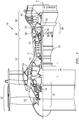
- FIG. 1 schematically illustrates a gas turbine engine 20.
- the gas turbine engine 20 as disclosed herein is a two spool turbofan that generally incorporates a fan section 22, a compressor section 24, a combustor section 26, and a turbine section 28.
- the fan section 22 drives air along a bypass flowpath while the compressor section 24 drives air along a core flowpath for compression and communication into the combustor section 26, then expansion through the turbine section 28.
- FIG. 1 schematically illustrates a gas turbine engine 20.
- the gas turbine engine 20 as disclosed herein is a two spool turbofan that generally incorporates a fan section 22, a compressor section 24, a combustor section 26, and a turbine section 28.
- the fan section 22 drives air along a bypass flowpath while the compressor section 24 drives air along a core flowpath for compression and communication into the combustor section 26, then expansion through the turbine section 28.
- FIG. 1 schematically illustrates a gas turbine engine 20.
- the gas turbine engine 20 as disclosed herein is a two
- the engine 20 generally includes a low spool 30 and a high spool 32 mounted for rotation around an engine central longitudinal axis A relative to an engine case structure 36 via several bearings 38.
- the low spool 30 generally includes an inner shaft 40 that interconnects a fan 42, a low pressure compressor (“LPC”) 44 and a low pressure turbine (“LPT”) 46.
- the inner shaft 40 drives the fan 42 directly or through a geared architecture 48 to drive the fan 42 at a lower speed than the low spool 30.
- An exemplary reduction transmission is an epicyclic transmission, namely a planetary or star gear system.
- the high spool 32 includes an outer shaft 50 that interconnects a high pressure compressor (“HPC”) 52 and high pressure turbine (“HPT”) 54.
- a combustor 56 is arranged between the HPC 52 and the HPT 54.
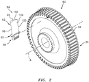
- a rotor assembly 60 such as turbine rotor assembly includes an array of blades 84 circumferentially disposed around a disk 86.
- Each blade 84 includes a root 88, a platform 90 and an airfoil 92.
- the blade roots 88 are received within a rim 94 of the disk 86 and the airfoils 92 extend radially outward.
- the platform 90 separates a gas path side inclusive of the airfoil 92 and a non-gas path side inclusive of the root 88.
- the airfoil 92 defines a blade chord between a leading edge 98, which may include various forward and/or aft sweep configurations, and a trailing edge 100.
- a first sidewall 102 that may be convex to define a suction side, and a second sidewall 104 that may be concave to define a pressure side are joined at the leading edge 98 and at the axially spaced trailing edge 100.
- the tip 96 extends between the sidewalls 102, 104 opposite the platform 90.
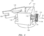
- a grit boot mask tool 120 includes a lock assembly 122 and a boot 124.
- the boot 124 may include an enclosure 126 that protects three sides, and a door 128 that completes the enclosure.
- the enclosure 126 may include various external shapes to facilitate retention within a fixture or other retention device.
- the door 128 may be hinged to the enclosure 126.
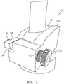
- the boot 124 in the illustrated embodiment may be manufactured of a rubber material that is internally shaped to receive, retain, and protect the root 88 and an underplatform area ( FIG. 4 ), however, other coating fixtures which protect other areas and other components will benefit herefrom.
- the boot 124 When fully assembled with the blade properly positioned in the boot 124, only a desired portion of the blade which is to be grit blasted such as the gas path side is exposed. That is, the boot 124 protects that which is not to be grit blasted.
- the lock assembly 122 generally includes a latch 130, a rod 132, a spring 134, and a knob 136.
- the latch 130 is transverse to the rod 132 and fits through a slot 138 in the door 128.
- the rod 132 extends through an aperture 140 in the enclosure 126.
- the spring 134 is compressed between the knob 136 and a washer 142 adjacent the enclosure so as to bias the rod 132, and thus the latch 130, toward the enclosure 126 (illustrated schematically by arrow W).
- Rotation of the latch 130 selectively provides a locked position transverse to the slot 138 ( FIG. 5 ) and an unlocked positon aligned with the slot 138.
- the lock assembly 122 in the illustrated embodiment requires only a quarter turn to lock or unlock the door 128 which provides an ergonomically friendly interface.
- the lock assembly 122 is also retained to the enclosure to avoid loss or damage.
Landscapes
- Engineering & Computer Science (AREA)
- Mechanical Engineering (AREA)
- General Engineering & Computer Science (AREA)
- Structures Of Non-Positive Displacement Pumps (AREA)
- Turbine Rotor Nozzle Sealing (AREA)
Abstract
Description
- The present disclosure relates generally to a grit boot mask tool and, more particularly, to a lock assembly for a grit boot mask tool.
- Gas turbine engines, such as those that power modern commercial and military aircraft, generally include a compressor section to pressurize an airflow, a combustor section to burn hydrocarbon fuel in the presence of the pressurized air, and a turbine section to extract energy from the resultant combustion gases. The compressor and turbine section include one or more arrays of blades extending radially outwardly from a rotor hub. Each blade has a root that mates with the hub to retain the blade. Each blade also has a platform that partly defines the radially inner boundary of an engine flowpath, and an airfoil that extends radially across the flowpath. During engine operation, a working gas, which flows axially through the flowpath, receives energy from the compressor blade arrays and provides energy to the turbine blade arrays.
- Those portions of the blades in direct contact with the working gas are subjected to a punishing operational environment. This is particularly true of the turbine blades, which are exposed to the elevated temperature and the effects of combustion products discharged from the engine combustion chamber. It is common practice to apply various protective coatings to the flowpath exposed surfaces of the blades to extend their useful life. Application of such coatings may often be proceeded by a grit blasting operation.
- Various protective grit boot mask tools have been devised to protect selected portions of the blade during grit blasting. Conventional tools use an enclosure with a door to receive the root of the blade. A wedge piece on the enclosure is friction fit with the door to retain the door during the grit blasting operation. Although effective, the wedge may wear over time which may result in the blade falling out of the boot during the grit blasting operation. This typically requires scrapping the blade.
- A grit boot mask tool according to one aspect of the present invention includes an enclosure to receive at least a portion of a blade; a door; and a lock assembly that retains the door to the enclosure.
- An embodiment of the above includes that the enclosure is internally shaped to receive a root of the blade.
- A further embodiment of any of the above includes that the enclosure is internally shaped to receive a root of the blade and at least a portion of a platform.
- A further embodiment of any of the above includes that the door is hinged with respect to the enclosure.
- A further embodiment of any of the above includes that the lock assembly comprises a spring biased latch.
- A further embodiment of any of the above includes that the lock assembly comprises a latch that is retained in a locked positon by a spring bias.
- A further embodiment of any of the above includes a knob to push the latch away from the enclosure to overcome the spring bias and rotate the latch.
- A further embodiment of any of the above includes that a quarter turn of the knob will lock and unlock the lock assembly.
- A further embodiment of any of the above includes that the latch is received through a slot in the door.
- A method of installing a grit boot mask tool to a blade according to one aspect of the present invention includes locating a portion of the blade in an enclosure; closing a door of the enclosure encasing the portion of the blade; and rotating a latch to retain the door to the enclosure.
- An embodiment of the above method includes that locating the portion of the blade in the enclosure comprises fitting a portion of a platform of the blade in the enclosure.
- A further embodiment of any of the above includes that locating the portion of the blade in the enclosure comprises fitting a root of the blade in the enclosure.
- A further embodiment of any of the above includes overcoming a bias on a lock assembly prior to rotating the latch.
- A further embodiment of any of the above includes pressing a knob to overcome the bias prior to rotating.
- A further embodiment of any of the above includes that rotating the latch comprises rotating a knob of a lock assembly one quarter turn.
- A further embodiment of any of the above includes that rotating the latch comprises rotating the latch transverse a slot in the door to lock the door.
- A further embodiment of any of the above includes that rotating the latch comprises aligning the latch with a slot in the door to unlock the door.
- The foregoing features and elements may be combined in various combinations without exclusivity, unless expressly indicated otherwise. These features and elements as well as the operation thereof will become more apparent in light of the following description and the accompanying drawings. It should be appreciated; however, the following description and drawings are intended to be exemplary in nature and non-limiting.
- Various features will become apparent to those skilled in the art from the following detailed description of the disclosed non-limiting embodiment. The drawings that accompany the detailed description can be briefly described as follows:
-
FIG. 1 is a partial cross-sectional illustration of a gas turbine engine. -
FIG. 2 is a partial cross-sectional illustration of a rotor hub of the gas turbine engine. -
FIG. 3 is a perspective view of a grit boot mask tool in an open positon. -
FIG. 4 is a perspective view of the grit boot mask tool in a closed position. -
FIG. 5 is a side view of the grit boot mask tool installed on a blade. -
FIG. 1 schematically illustrates agas turbine engine 20. Thegas turbine engine 20 as disclosed herein is a two spool turbofan that generally incorporates afan section 22, acompressor section 24, acombustor section 26, and aturbine section 28. Thefan section 22 drives air along a bypass flowpath while thecompressor section 24 drives air along a core flowpath for compression and communication into thecombustor section 26, then expansion through theturbine section 28. Although depicted as a high bypass gas turbofan engine architecture in the disclosed non-limiting embodiment, it should be appreciated that the concepts described herein are not limited only thereto. - The
engine 20 generally includes alow spool 30 and ahigh spool 32 mounted for rotation around an engine central longitudinal axis A relative to anengine case structure 36 viaseveral bearings 38. Thelow spool 30 generally includes aninner shaft 40 that interconnects afan 42, a low pressure compressor ("LPC") 44 and a low pressure turbine ("LPT") 46. Theinner shaft 40 drives thefan 42 directly or through a gearedarchitecture 48 to drive thefan 42 at a lower speed than thelow spool 30. An exemplary reduction transmission is an epicyclic transmission, namely a planetary or star gear system. Thehigh spool 32 includes anouter shaft 50 that interconnects a high pressure compressor ("HPC") 52 and high pressure turbine ("HPT") 54. Acombustor 56 is arranged between the HPC 52 and the HPT 54. - With reference to
FIG. 2 , arotor assembly 60 such as turbine rotor assembly includes an array ofblades 84 circumferentially disposed around adisk 86. Eachblade 84 includes aroot 88, aplatform 90 and anairfoil 92. Theblade roots 88 are received within arim 94 of thedisk 86 and theairfoils 92 extend radially outward. - The
platform 90 separates a gas path side inclusive of theairfoil 92 and a non-gas path side inclusive of theroot 88. Theairfoil 92 defines a blade chord between a leadingedge 98, which may include various forward and/or aft sweep configurations, and atrailing edge 100. Afirst sidewall 102 that may be convex to define a suction side, and asecond sidewall 104 that may be concave to define a pressure side are joined at the leadingedge 98 and at the axially spacedtrailing edge 100. Thetip 96 extends between thesidewalls platform 90. - With reference to
FIG. 3 , a gritboot mask tool 120 includes alock assembly 122 and aboot 124. Theboot 124 may include anenclosure 126 that protects three sides, and adoor 128 that completes the enclosure. Theenclosure 126 may include various external shapes to facilitate retention within a fixture or other retention device. Thedoor 128 may be hinged to theenclosure 126. Theboot 124 in the illustrated embodiment may be manufactured of a rubber material that is internally shaped to receive, retain, and protect theroot 88 and an underplatform area (FIG. 4 ), however, other coating fixtures which protect other areas and other components will benefit herefrom. When fully assembled with the blade properly positioned in theboot 124, only a desired portion of the blade which is to be grit blasted such as the gas path side is exposed. That is, theboot 124 protects that which is not to be grit blasted. - The
lock assembly 122 generally includes alatch 130, arod 132, aspring 134, and aknob 136. Thelatch 130 is transverse to therod 132 and fits through aslot 138 in thedoor 128. Therod 132 extends through anaperture 140 in theenclosure 126. Thespring 134 is compressed between theknob 136 and awasher 142 adjacent the enclosure so as to bias therod 132, and thus thelatch 130, toward the enclosure 126 (illustrated schematically by arrow W). Rotation of thelatch 130 selectively provides a locked position transverse to the slot 138 (FIG. 5 ) and an unlocked positon aligned with theslot 138. - The
lock assembly 122 in the illustrated embodiment requires only a quarter turn to lock or unlock thedoor 128 which provides an ergonomically friendly interface. Thelock assembly 122 is also retained to the enclosure to avoid loss or damage. - The use of the terms "a," and "an," and "the," and similar references in the context of description (especially in the context of the following claims) are to be construed to cover both the singular and the plural, unless otherwise indicated herein or specifically contradicted by context. The modifier "about" used in connection with a quantity is inclusive of the stated value and has the meaning dictated by the context (e.g., it includes the degree of error associated with measurement of the particular quantity). All ranges disclosed herein are inclusive of the endpoints, and the endpoints are independently combinable with each other. It should be appreciated that relative positional terms such as "forward," "aft," "upper," "lower," "above," "below," and the like are with reference to the normal operational attitude of the vehicle and should not be considered otherwise limiting.
- Although the different non-limiting embodiments have specific illustrated components, the embodiments of this invention are not limited to those particular combinations. It is possible to use some of the components or features from any of the non-limiting embodiments in combination with features or components from any of the other non-limiting embodiments.
- It should be appreciated that like reference numerals identify corresponding or similar elements throughout the several drawings. It should also be appreciated that although a particular component arrangement is disclosed in the illustrated embodiment, other arrangements will benefit herefrom.
- Although particular step sequences are shown, described, and claimed, it should be understood that steps may be performed in any order, separated or combined unless otherwise indicated and will still benefit from the present disclosure.
- The foregoing description is exemplary rather than defined by the limitations within. Various non-limiting embodiments are disclosed herein, however, one of ordinary skill in the art would recognize that various modifications and variations in light of the above teachings will fall within the scope of the appended claims. It is therefore to be understood that within the scope of the appended claims, the disclosure may be practiced other than as specifically described. For that reason, the appended claims should be studied to determine true scope and content.
Claims (15)
- A grit boot mask tool (120), comprising:an enclosure (126) to receive at least a portion of a blade (84);a door (128); anda lock assembly (122) that retains the door (128) to the enclosure (126).
- The grit boot mask tool as recited in claim 1, wherein the enclosure (126) is internally shaped to receive a root (88) of a blade (84).
- The grit boot mask tool as recited in claim 1, wherein the enclosure (126) is internally shaped to receive a root (88) and at least a portion of a platform (90) of a blade (84).
- The grit boot mask tool as recited in claim 1, 2 or 3, wherein the door (128) is hinged with respect to the enclosure (126).
- The grit boot mask tool as recited in any preceding claim, wherein the lock assembly (122) comprises a spring biased latch (130).
- The grit boot mask tool as recited in any of claims 1 to 4, wherein the lock assembly (122) comprises a latch (130) that is retained in a locked positon by a spring bias.
- The grit boot mask tool as recited in claim 5 or 6, further comprising a knob (136) to push the latch (130) away from the enclosure (126) to overcome the spring bias and rotate the latch (130).
- The grit boot mask tool as recited in claim 7, wherein a quarter turn of the knob (136) will lock and unlock the lock assembly (122).
- The grit boot mask tool as recited in any of claims 5 to 8, wherein the latch (130) is received through a slot (138) in the door (128).
- A method of installing a grit boot mask tool (120) to a blade (184), comprising:locating a portion of the blade (84) in an enclosure (126);closing a door (128) of the enclosure (126) encasing the portion of the blade (84); androtating a latch (130) to retain the door (128) to the enclosure (126).
- The method as recited in claim 10, wherein locating the portion of the blade (84) in the enclosure (126) comprises fitting a portion of a platform (90) of the blade (84) in the enclosure (126).
- The method as recited in claim 10 or 11, wherein locating the portion of the blade (84) in the enclosure (126) comprises fitting a root (88) of the blade (84) in the enclosure (126).
- The method as recited in claim 10, 11 or 12, further comprising overcoming a bias on a lock assembly (122) prior to rotating the latch (130), optionally by pressing a knob (136).
- The method as recited in any of claims 10 to 13, wherein rotating the latch comprises rotating a knob of a lock assembly one quarter turn.
- The method as recited in any of claims 10 to 14, wherein rotating the latch comprises rotating the latch transverse a slot in the door to lock the door, and/or further comprising rotating the latch to unlock the door by aligning the latch with a or the slot in the door.
Applications Claiming Priority (1)
| Application Number | Priority Date | Filing Date | Title |
|---|---|---|---|
| US15/871,305 US10722912B2 (en) | 2018-01-15 | 2018-01-15 | Lock assembly for grit boot mask tool |
Publications (2)
| Publication Number | Publication Date |
|---|---|
| EP3511113A1 true EP3511113A1 (en) | 2019-07-17 |
| EP3511113B1 EP3511113B1 (en) | 2022-05-11 |
Family
ID=65243308
Family Applications (1)
| Application Number | Title | Priority Date | Filing Date |
|---|---|---|---|
| EP19151946.1A Active EP3511113B1 (en) | 2018-01-15 | 2019-01-15 | Grit boot mask tool and method for enclosing a blade in the tool |
Country Status (2)
| Country | Link |
|---|---|
| US (1) | US10722912B2 (en) |
| EP (1) | EP3511113B1 (en) |
Families Citing this family (4)
| Publication number | Priority date | Publication date | Assignee | Title |
|---|---|---|---|---|
| CN114952637B (en) * | 2021-12-28 | 2024-07-23 | 无锡透平叶片有限公司 | Protective clamp for multi-combined combustion engine blade shot blasting |
| CN116000565B (en) * | 2022-12-08 | 2025-10-24 | 中国航发南方工业有限公司 | Preparation method of serrated shroud turbine blade protection fixture and protection fixture thereof |
| US20250250914A1 (en) * | 2024-02-01 | 2025-08-07 | Chromalloy Gas Turbine Llc | Tooling and method for masking a turbine component such as a blade or vane |
| FR3161133A1 (en) * | 2024-04-15 | 2025-10-17 | Safran Aircraft Engines | Blade root area control tooling |
Citations (12)
| Publication number | Priority date | Publication date | Assignee | Title |
|---|---|---|---|---|
| US3862773A (en) * | 1973-08-06 | 1975-01-28 | Southco | Push-release fastener |
| US5645466A (en) * | 1994-06-17 | 1997-07-08 | Wikle; Kenneth C. | Apparatus and method for contour grinding gas turbine blades |
| US5792267A (en) * | 1997-05-16 | 1998-08-11 | United Technologies Corporation | Coating fixture for a turbine engine blade |
| US5849359A (en) * | 1997-07-17 | 1998-12-15 | United Technologies Corporation | Variable tilting tumbler vacuum coating apparatus |
| US5998755A (en) * | 1997-12-19 | 1999-12-07 | United Technologies Corporation | Tooling assembly for positioning airfoils of a rotary machine |
| US20040043231A1 (en) * | 2002-08-27 | 2004-03-04 | Sulzer Metco Ag | Guide apparatus for a workpiece having a porous surface coating as well as to a method for the polishing of such a workpiece |
| FR2879117A1 (en) * | 2004-12-15 | 2006-06-16 | Malichaud Atlantique Soc Par A | Part e.g. turbine blade, machining method, involves set of locking staves in position, where one stave is deployed in same direction as that of positioning stave and supports machining efforts by replacing positioning stave |
| EP1884312A1 (en) * | 2006-08-04 | 2008-02-06 | Ansaldo Energia S.P.A. | A device for blocking a blade of a turbine and a method for blade machining using said blocking device |
| US20090165519A1 (en) * | 2006-05-26 | 2009-07-02 | Thomas Berndt | Peening Device |
| EP2145734A1 (en) * | 2008-07-17 | 2010-01-20 | Ansaldo Energia S.P.A. | Vice for withholding a turbine blade |
| US20130167337A1 (en) * | 2010-09-15 | 2013-07-04 | Snecma | Method and machine tool for adjusting the contour of a turbine blade root |
| CN107138325B (en) * | 2017-06-02 | 2019-03-22 | 中国航发南方工业有限公司 | Blade sprays Protecting clamping apparatus |
Family Cites Families (8)
| Publication number | Priority date | Publication date | Assignee | Title |
|---|---|---|---|---|
| US4695486A (en) * | 1980-08-08 | 1987-09-22 | Stark William C | Paint shields and painting methods |
| US4704987A (en) * | 1986-03-27 | 1987-11-10 | Libbey-Owens-Ford Co. | Painting mask and fixture |
| US6037004A (en) | 1997-12-19 | 2000-03-14 | United Technologies Corporation | Shield and method for protecting an airfoil surface |
| JP3653178B2 (en) * | 1998-07-22 | 2005-05-25 | 株式会社小糸製作所 | Paint mask device |
| JP2001038263A (en) * | 1999-08-04 | 2001-02-13 | Koito Mfg Co Ltd | Painting mask device |
| JP3742254B2 (en) * | 1999-08-09 | 2006-02-01 | 株式会社小糸製作所 | Paint mask device |
| JP3742255B2 (en) * | 1999-09-07 | 2006-02-01 | 株式会社小糸製作所 | Mask for painting plastic products |
| CN106346369B (en) | 2016-09-30 | 2018-04-20 | 中国南方航空工业(集团)有限公司 | Hollow porous blade pressure difference blast method and fixture |
-
2018
- 2018-01-15 US US15/871,305 patent/US10722912B2/en active Active
-
2019
- 2019-01-15 EP EP19151946.1A patent/EP3511113B1/en active Active
Patent Citations (12)
| Publication number | Priority date | Publication date | Assignee | Title |
|---|---|---|---|---|
| US3862773A (en) * | 1973-08-06 | 1975-01-28 | Southco | Push-release fastener |
| US5645466A (en) * | 1994-06-17 | 1997-07-08 | Wikle; Kenneth C. | Apparatus and method for contour grinding gas turbine blades |
| US5792267A (en) * | 1997-05-16 | 1998-08-11 | United Technologies Corporation | Coating fixture for a turbine engine blade |
| US5849359A (en) * | 1997-07-17 | 1998-12-15 | United Technologies Corporation | Variable tilting tumbler vacuum coating apparatus |
| US5998755A (en) * | 1997-12-19 | 1999-12-07 | United Technologies Corporation | Tooling assembly for positioning airfoils of a rotary machine |
| US20040043231A1 (en) * | 2002-08-27 | 2004-03-04 | Sulzer Metco Ag | Guide apparatus for a workpiece having a porous surface coating as well as to a method for the polishing of such a workpiece |
| FR2879117A1 (en) * | 2004-12-15 | 2006-06-16 | Malichaud Atlantique Soc Par A | Part e.g. turbine blade, machining method, involves set of locking staves in position, where one stave is deployed in same direction as that of positioning stave and supports machining efforts by replacing positioning stave |
| US20090165519A1 (en) * | 2006-05-26 | 2009-07-02 | Thomas Berndt | Peening Device |
| EP1884312A1 (en) * | 2006-08-04 | 2008-02-06 | Ansaldo Energia S.P.A. | A device for blocking a blade of a turbine and a method for blade machining using said blocking device |
| EP2145734A1 (en) * | 2008-07-17 | 2010-01-20 | Ansaldo Energia S.P.A. | Vice for withholding a turbine blade |
| US20130167337A1 (en) * | 2010-09-15 | 2013-07-04 | Snecma | Method and machine tool for adjusting the contour of a turbine blade root |
| CN107138325B (en) * | 2017-06-02 | 2019-03-22 | 中国航发南方工业有限公司 | Blade sprays Protecting clamping apparatus |
Also Published As
| Publication number | Publication date |
|---|---|
| US10722912B2 (en) | 2020-07-28 |
| US20190217321A1 (en) | 2019-07-18 |
| EP3511113B1 (en) | 2022-05-11 |
Similar Documents
| Publication | Publication Date | Title |
|---|---|---|
| EP2995777B1 (en) | Vane ring for a gas turbine engine | |
| EP3511113B1 (en) | Grit boot mask tool and method for enclosing a blade in the tool | |
| US8246310B2 (en) | Turbomachine fan | |
| EP2998520B1 (en) | Inter stage seal for gas turbine engine | |
| EP3431712B1 (en) | Method to strip and recoat erosion coatings applied to fan blades and structural guide vanes | |
| US10895159B2 (en) | Removable anti-wear part for blade tip | |
| EP3170988B1 (en) | Rotor for gas turbine engine | |
| US20130071254A1 (en) | Turbine blades and methods of forming modified turbine blades and turbine rotors | |
| US20160017735A1 (en) | Vane tip machining fixture assembly | |
| US10689988B2 (en) | Disk lug impingement for gas turbine engine airfoil | |
| US20190010813A1 (en) | Cover plate for rotor assembly of a gas turbine engine | |
| US20130052026A1 (en) | Axial retention system for a bladed rotor with multiple blade types | |
| US9737970B2 (en) | Vibratory mass media fixture with tip protector | |
| EP3869010B1 (en) | Tangential rotor blade slot spacer for a gas turbine engine | |
| EP3287601B1 (en) | Multi-piece non-linear fan blade | |
| CN102261266A (en) | Turbine blade walking prevention | |
| EP2434099B1 (en) | Blade for a gas turbine engine | |
| EP3524384A1 (en) | Additively manufactured airflow mask tool | |
| EP3578759B1 (en) | Airfoil and corresponding method of directing a cooling flow | |
| EP3044426B1 (en) | Method for repairing turbine components | |
| US20190330999A1 (en) | Gas turbine engine flow modulation in a rotating vane |
Legal Events
| Date | Code | Title | Description |
|---|---|---|---|
| PUAI | Public reference made under article 153(3) epc to a published international application that has entered the european phase |
Free format text: ORIGINAL CODE: 0009012 |
|
| STAA | Information on the status of an ep patent application or granted ep patent |
Free format text: STATUS: THE APPLICATION HAS BEEN PUBLISHED |
|
| AK | Designated contracting states |
Kind code of ref document: A1 Designated state(s): AL AT BE BG CH CY CZ DE DK EE ES FI FR GB GR HR HU IE IS IT LI LT LU LV MC MK MT NL NO PL PT RO RS SE SI SK SM TR |
|
| AX | Request for extension of the european patent |
Extension state: BA ME |
|
| STAA | Information on the status of an ep patent application or granted ep patent |
Free format text: STATUS: REQUEST FOR EXAMINATION WAS MADE |
|
| 17P | Request for examination filed |
Effective date: 20200117 |
|
| RBV | Designated contracting states (corrected) |
Designated state(s): AL AT BE BG CH CY CZ DE DK EE ES FI FR GB GR HR HU IE IS IT LI LT LU LV MC MK MT NL NO PL PT RO RS SE SI SK SM TR |
|
| RAP1 | Party data changed (applicant data changed or rights of an application transferred) |
Owner name: RAYTHEON TECHNOLOGIES CORPORATION |
|
| GRAP | Despatch of communication of intention to grant a patent |
Free format text: ORIGINAL CODE: EPIDOSNIGR1 |
|
| STAA | Information on the status of an ep patent application or granted ep patent |
Free format text: STATUS: GRANT OF PATENT IS INTENDED |
|
| INTG | Intention to grant announced |
Effective date: 20211126 |
|
| GRAS | Grant fee paid |
Free format text: ORIGINAL CODE: EPIDOSNIGR3 |
|
| GRAA | (expected) grant |
Free format text: ORIGINAL CODE: 0009210 |
|
| STAA | Information on the status of an ep patent application or granted ep patent |
Free format text: STATUS: THE PATENT HAS BEEN GRANTED |
|
| AK | Designated contracting states |
Kind code of ref document: B1 Designated state(s): AL AT BE BG CH CY CZ DE DK EE ES FI FR GB GR HR HU IE IS IT LI LT LU LV MC MK MT NL NO PL PT RO RS SE SI SK SM TR |
|
| REG | Reference to a national code |
Ref country code: GB Ref legal event code: FG4D |
|
| REG | Reference to a national code |
Ref country code: CH Ref legal event code: EP |
|
| REG | Reference to a national code |
Ref country code: AT Ref legal event code: REF Ref document number: 1490979 Country of ref document: AT Kind code of ref document: T Effective date: 20220515 |
|
| REG | Reference to a national code |
Ref country code: DE Ref legal event code: R096 Ref document number: 602019014696 Country of ref document: DE |
|
| REG | Reference to a national code |
Ref country code: IE Ref legal event code: FG4D |
|
| REG | Reference to a national code |
Ref country code: LT Ref legal event code: MG9D |
|
| REG | Reference to a national code |
Ref country code: NL Ref legal event code: MP Effective date: 20220511 |
|
| REG | Reference to a national code |
Ref country code: AT Ref legal event code: MK05 Ref document number: 1490979 Country of ref document: AT Kind code of ref document: T Effective date: 20220511 |
|
| PG25 | Lapsed in a contracting state [announced via postgrant information from national office to epo] |
Ref country code: SE Free format text: LAPSE BECAUSE OF FAILURE TO SUBMIT A TRANSLATION OF THE DESCRIPTION OR TO PAY THE FEE WITHIN THE PRESCRIBED TIME-LIMIT Effective date: 20220511 Ref country code: PT Free format text: LAPSE BECAUSE OF FAILURE TO SUBMIT A TRANSLATION OF THE DESCRIPTION OR TO PAY THE FEE WITHIN THE PRESCRIBED TIME-LIMIT Effective date: 20220912 Ref country code: NO Free format text: LAPSE BECAUSE OF FAILURE TO SUBMIT A TRANSLATION OF THE DESCRIPTION OR TO PAY THE FEE WITHIN THE PRESCRIBED TIME-LIMIT Effective date: 20220811 Ref country code: NL Free format text: LAPSE BECAUSE OF FAILURE TO SUBMIT A TRANSLATION OF THE DESCRIPTION OR TO PAY THE FEE WITHIN THE PRESCRIBED TIME-LIMIT Effective date: 20220511 Ref country code: LT Free format text: LAPSE BECAUSE OF FAILURE TO SUBMIT A TRANSLATION OF THE DESCRIPTION OR TO PAY THE FEE WITHIN THE PRESCRIBED TIME-LIMIT Effective date: 20220511 Ref country code: HR Free format text: LAPSE BECAUSE OF FAILURE TO SUBMIT A TRANSLATION OF THE DESCRIPTION OR TO PAY THE FEE WITHIN THE PRESCRIBED TIME-LIMIT Effective date: 20220511 Ref country code: GR Free format text: LAPSE BECAUSE OF FAILURE TO SUBMIT A TRANSLATION OF THE DESCRIPTION OR TO PAY THE FEE WITHIN THE PRESCRIBED TIME-LIMIT Effective date: 20220812 Ref country code: FI Free format text: LAPSE BECAUSE OF FAILURE TO SUBMIT A TRANSLATION OF THE DESCRIPTION OR TO PAY THE FEE WITHIN THE PRESCRIBED TIME-LIMIT Effective date: 20220511 Ref country code: ES Free format text: LAPSE BECAUSE OF FAILURE TO SUBMIT A TRANSLATION OF THE DESCRIPTION OR TO PAY THE FEE WITHIN THE PRESCRIBED TIME-LIMIT Effective date: 20220511 Ref country code: BG Free format text: LAPSE BECAUSE OF FAILURE TO SUBMIT A TRANSLATION OF THE DESCRIPTION OR TO PAY THE FEE WITHIN THE PRESCRIBED TIME-LIMIT Effective date: 20220811 Ref country code: AT Free format text: LAPSE BECAUSE OF FAILURE TO SUBMIT A TRANSLATION OF THE DESCRIPTION OR TO PAY THE FEE WITHIN THE PRESCRIBED TIME-LIMIT Effective date: 20220511 |
|
| PG25 | Lapsed in a contracting state [announced via postgrant information from national office to epo] |
Ref country code: RS Free format text: LAPSE BECAUSE OF FAILURE TO SUBMIT A TRANSLATION OF THE DESCRIPTION OR TO PAY THE FEE WITHIN THE PRESCRIBED TIME-LIMIT Effective date: 20220511 Ref country code: PL Free format text: LAPSE BECAUSE OF FAILURE TO SUBMIT A TRANSLATION OF THE DESCRIPTION OR TO PAY THE FEE WITHIN THE PRESCRIBED TIME-LIMIT Effective date: 20220511 Ref country code: LV Free format text: LAPSE BECAUSE OF FAILURE TO SUBMIT A TRANSLATION OF THE DESCRIPTION OR TO PAY THE FEE WITHIN THE PRESCRIBED TIME-LIMIT Effective date: 20220511 Ref country code: IS Free format text: LAPSE BECAUSE OF FAILURE TO SUBMIT A TRANSLATION OF THE DESCRIPTION OR TO PAY THE FEE WITHIN THE PRESCRIBED TIME-LIMIT Effective date: 20220911 |
|
| PG25 | Lapsed in a contracting state [announced via postgrant information from national office to epo] |
Ref country code: SM Free format text: LAPSE BECAUSE OF FAILURE TO SUBMIT A TRANSLATION OF THE DESCRIPTION OR TO PAY THE FEE WITHIN THE PRESCRIBED TIME-LIMIT Effective date: 20220511 Ref country code: SK Free format text: LAPSE BECAUSE OF FAILURE TO SUBMIT A TRANSLATION OF THE DESCRIPTION OR TO PAY THE FEE WITHIN THE PRESCRIBED TIME-LIMIT Effective date: 20220511 Ref country code: RO Free format text: LAPSE BECAUSE OF FAILURE TO SUBMIT A TRANSLATION OF THE DESCRIPTION OR TO PAY THE FEE WITHIN THE PRESCRIBED TIME-LIMIT Effective date: 20220511 Ref country code: EE Free format text: LAPSE BECAUSE OF FAILURE TO SUBMIT A TRANSLATION OF THE DESCRIPTION OR TO PAY THE FEE WITHIN THE PRESCRIBED TIME-LIMIT Effective date: 20220511 Ref country code: DK Free format text: LAPSE BECAUSE OF FAILURE TO SUBMIT A TRANSLATION OF THE DESCRIPTION OR TO PAY THE FEE WITHIN THE PRESCRIBED TIME-LIMIT Effective date: 20220511 Ref country code: CZ Free format text: LAPSE BECAUSE OF FAILURE TO SUBMIT A TRANSLATION OF THE DESCRIPTION OR TO PAY THE FEE WITHIN THE PRESCRIBED TIME-LIMIT Effective date: 20220511 |
|
| REG | Reference to a national code |
Ref country code: DE Ref legal event code: R097 Ref document number: 602019014696 Country of ref document: DE |
|
| PLBE | No opposition filed within time limit |
Free format text: ORIGINAL CODE: 0009261 |
|
| STAA | Information on the status of an ep patent application or granted ep patent |
Free format text: STATUS: NO OPPOSITION FILED WITHIN TIME LIMIT |
|
| PG25 | Lapsed in a contracting state [announced via postgrant information from national office to epo] |
Ref country code: AL Free format text: LAPSE BECAUSE OF FAILURE TO SUBMIT A TRANSLATION OF THE DESCRIPTION OR TO PAY THE FEE WITHIN THE PRESCRIBED TIME-LIMIT Effective date: 20220511 |
|
| 26N | No opposition filed |
Effective date: 20230214 |
|
| PG25 | Lapsed in a contracting state [announced via postgrant information from national office to epo] |
Ref country code: SI Free format text: LAPSE BECAUSE OF FAILURE TO SUBMIT A TRANSLATION OF THE DESCRIPTION OR TO PAY THE FEE WITHIN THE PRESCRIBED TIME-LIMIT Effective date: 20220511 |
|
| P01 | Opt-out of the competence of the unified patent court (upc) registered |
Effective date: 20230521 |
|
| REG | Reference to a national code |
Ref country code: CH Ref legal event code: PL |
|
| PG25 | Lapsed in a contracting state [announced via postgrant information from national office to epo] |
Ref country code: LU Free format text: LAPSE BECAUSE OF NON-PAYMENT OF DUE FEES Effective date: 20230115 |
|
| REG | Reference to a national code |
Ref country code: BE Ref legal event code: MM Effective date: 20230131 |
|
| PG25 | Lapsed in a contracting state [announced via postgrant information from national office to epo] |
Ref country code: LI Free format text: LAPSE BECAUSE OF NON-PAYMENT OF DUE FEES Effective date: 20230131 Ref country code: CH Free format text: LAPSE BECAUSE OF NON-PAYMENT OF DUE FEES Effective date: 20230131 |
|
| PG25 | Lapsed in a contracting state [announced via postgrant information from national office to epo] |
Ref country code: BE Free format text: LAPSE BECAUSE OF NON-PAYMENT OF DUE FEES Effective date: 20230131 |
|
| PG25 | Lapsed in a contracting state [announced via postgrant information from national office to epo] |
Ref country code: IT Free format text: LAPSE BECAUSE OF FAILURE TO SUBMIT A TRANSLATION OF THE DESCRIPTION OR TO PAY THE FEE WITHIN THE PRESCRIBED TIME-LIMIT Effective date: 20220511 Ref country code: IE Free format text: LAPSE BECAUSE OF NON-PAYMENT OF DUE FEES Effective date: 20230115 |
|
| PG25 | Lapsed in a contracting state [announced via postgrant information from national office to epo] |
Ref country code: MC Free format text: LAPSE BECAUSE OF FAILURE TO SUBMIT A TRANSLATION OF THE DESCRIPTION OR TO PAY THE FEE WITHIN THE PRESCRIBED TIME-LIMIT Effective date: 20220511 |
|
| PG25 | Lapsed in a contracting state [announced via postgrant information from national office to epo] |
Ref country code: MC Free format text: LAPSE BECAUSE OF FAILURE TO SUBMIT A TRANSLATION OF THE DESCRIPTION OR TO PAY THE FEE WITHIN THE PRESCRIBED TIME-LIMIT Effective date: 20220511 |
|
| PG25 | Lapsed in a contracting state [announced via postgrant information from national office to epo] |
Ref country code: BG Free format text: LAPSE BECAUSE OF FAILURE TO SUBMIT A TRANSLATION OF THE DESCRIPTION OR TO PAY THE FEE WITHIN THE PRESCRIBED TIME-LIMIT Effective date: 20220511 |
|
| PG25 | Lapsed in a contracting state [announced via postgrant information from national office to epo] |
Ref country code: BG Free format text: LAPSE BECAUSE OF FAILURE TO SUBMIT A TRANSLATION OF THE DESCRIPTION OR TO PAY THE FEE WITHIN THE PRESCRIBED TIME-LIMIT Effective date: 20220511 |
|
| PG25 | Lapsed in a contracting state [announced via postgrant information from national office to epo] |
Ref country code: CY Free format text: LAPSE BECAUSE OF FAILURE TO SUBMIT A TRANSLATION OF THE DESCRIPTION OR TO PAY THE FEE WITHIN THE PRESCRIBED TIME-LIMIT; INVALID AB INITIO Effective date: 20190115 |
|
| PG25 | Lapsed in a contracting state [announced via postgrant information from national office to epo] |
Ref country code: HU Free format text: LAPSE BECAUSE OF FAILURE TO SUBMIT A TRANSLATION OF THE DESCRIPTION OR TO PAY THE FEE WITHIN THE PRESCRIBED TIME-LIMIT; INVALID AB INITIO Effective date: 20190115 |
|
| REG | Reference to a national code |
Ref country code: DE Ref legal event code: R081 Ref document number: 602019014696 Country of ref document: DE Owner name: RTX CORPORATION (N.D.GES.D. STAATES DELAWARE),, US Free format text: FORMER OWNER: RAYTHEON TECHNOLOGIES CORP., FARMINGTON, CT, US |
|
| PG25 | Lapsed in a contracting state [announced via postgrant information from national office to epo] |
Ref country code: TR Free format text: LAPSE BECAUSE OF FAILURE TO SUBMIT A TRANSLATION OF THE DESCRIPTION OR TO PAY THE FEE WITHIN THE PRESCRIBED TIME-LIMIT Effective date: 20220511 |
|
| PGFP | Annual fee paid to national office [announced via postgrant information from national office to epo] |
Ref country code: GB Payment date: 20251220 Year of fee payment: 8 |
|
| PGFP | Annual fee paid to national office [announced via postgrant information from national office to epo] |
Ref country code: FR Payment date: 20251217 Year of fee payment: 8 |
|
| PGFP | Annual fee paid to national office [announced via postgrant information from national office to epo] |
Ref country code: DE Payment date: 20251217 Year of fee payment: 8 |