EP3510795B1 - Pfadmodellierung von akustischem feedback für hörgerät - Google Patents
Pfadmodellierung von akustischem feedback für hörgerät Download PDFInfo
- Publication number
- EP3510795B1 EP3510795B1 EP17772548.8A EP17772548A EP3510795B1 EP 3510795 B1 EP3510795 B1 EP 3510795B1 EP 17772548 A EP17772548 A EP 17772548A EP 3510795 B1 EP3510795 B1 EP 3510795B1
- Authority
- EP
- European Patent Office
- Prior art keywords
- invariant portion
- filter
- feedback
- invariant
- predetermined number
- Prior art date
- Legal status (The legal status is an assumption and is not a legal conclusion. Google has not performed a legal analysis and makes no representation as to the accuracy of the status listed.)
- Active
Links
Images


Classifications
-
- H—ELECTRICITY
- H04—ELECTRIC COMMUNICATION TECHNIQUE
- H04R—LOUDSPEAKERS, MICROPHONES, GRAMOPHONE PICK-UPS OR LIKE ACOUSTIC ELECTROMECHANICAL TRANSDUCERS; DEAF-AID SETS; PUBLIC ADDRESS SYSTEMS
- H04R25/00—Deaf-aid sets, i.e. electro-acoustic or electro-mechanical hearing aids; Electric tinnitus maskers providing an auditory perception
- H04R25/70—Adaptation of deaf aid to hearing loss, e.g. initial electronic fitting
-
- H—ELECTRICITY
- H04—ELECTRIC COMMUNICATION TECHNIQUE
- H04R—LOUDSPEAKERS, MICROPHONES, GRAMOPHONE PICK-UPS OR LIKE ACOUSTIC ELECTROMECHANICAL TRANSDUCERS; DEAF-AID SETS; PUBLIC ADDRESS SYSTEMS
- H04R25/00—Deaf-aid sets, i.e. electro-acoustic or electro-mechanical hearing aids; Electric tinnitus maskers providing an auditory perception
- H04R25/45—Prevention of acoustic reaction, i.e. acoustic oscillatory feedback
- H04R25/453—Prevention of acoustic reaction, i.e. acoustic oscillatory feedback electronically
-
- H—ELECTRICITY
- H04—ELECTRIC COMMUNICATION TECHNIQUE
- H04R—LOUDSPEAKERS, MICROPHONES, GRAMOPHONE PICK-UPS OR LIKE ACOUSTIC ELECTROMECHANICAL TRANSDUCERS; DEAF-AID SETS; PUBLIC ADDRESS SYSTEMS
- H04R25/00—Deaf-aid sets, i.e. electro-acoustic or electro-mechanical hearing aids; Electric tinnitus maskers providing an auditory perception
- H04R25/50—Customised settings for obtaining desired overall acoustical characteristics
- H04R25/505—Customised settings for obtaining desired overall acoustical characteristics using digital signal processing
Definitions
- This disclosure relates generally to hearing assistance devices and more particularly to acoustic feedback path modeling for hearing assistance devices.
- Hearing assistance devices such as hearing aids, can be used to assist patients suffering hearing loss by transmitting amplified sounds to one or both ear canals.
- a hearing aid can be worn in and/or around a patient's ear.
- Acoustic feedback in digital hearing aids usually occurs because of the coupling between the receiver, i.e., the speaker and the hearing aid microphone, which results in distortion of the desired sound and can lead to whistling sounds.
- whistling sounds have become a common problem associated with the current generation of digital hearing aids and therefore efficient strategies to prevent the howling sounds are desirable to reduce distortion of the desired sound and control whistling.
- HENNING SCHEPKER ET AL "Least-squares estimation of the common pole-zero filter of acoustic feedback paths in hearing aids", IEEE/ACM TRANSACTIONS ON AUDIO, SPEECH, AND LANGUAGE PROCESSING, IEEE, USA, vol. 24, no. 8, 1 August 2016, pages 1334-1347 describe in adaptive feedback cancellation both the convergence speed and the computational complexity depend on the number of adaptive parameters used to model the acoustic feedback paths. To reduce the number of adaptive parameters, it has been proposed to model the acoustic feedback paths as the convolution of a time-invariant common pole-zero filter and time-varying all-zero filters, enabling to track fast changes.
- MA GUILIN ET AL "Extracting the invariant model from the feedback paths of digital hearing aids", THE JOURNAL OF THE ACOUSTICAL SOCIETY OF AMERICA, AMERICAN INSTITUTE OF PHYSICS FOR THE ACOUSTICAL SOCIETY OF AMERICA, NEW YORK, NY, US, vol. 130, no. 1, 1 July 2011, pages 350-363 describe feedback whistling is a severe problem with hearing aids.
- a typical acoustical feedback path represents a wave propagation path from the receiver to the microphone and includes many complicated effects among which some are invariant or nearly invariant for all users and in all acoustical environments given a specific type of hearing aids.
- a feedback path model that consists of an invariant model and a variant model is proposed.
- a common-acoustical-pole and zero model-based approach and an iterative least-square search-based approach are used to extract the invariant model from a set of impulse responses of the feedback paths.
- a hybrid approach combining the two methods is also proposed. The general properties of the three methods are studied using artificial datasets, and the methods are cross-validated using the measured feedback paths. The results show that the proposed hybrid method gives the best overall performance, and the extracted invariant model is effective in modeling the feedback path.
- GIRI RITWIK ET AL "Dynamic relative impulse response estimation using structured sparse Bayesian learning", 2016 IEEE INTERNATIONAL CONFERENCE ON ACOUSTICS, SPEECH AND SIGNAL PROCESSING (ICASSP), 20 March 2016, pages 514-518 describe Hierarchical Bayesian approach to estimate Relative Impulse Response (ReIR) using short, noisy and reverberant microphone recordings.
- ReIR Relative Impulse Response
- the information contained in ReIRs between two microphones is useful for a wide range of multichannel speech processing applications such as speaker localization, speech enhancement, etc.
- RTF Relative Transfer Function
- a structured sparse Bayesian learning algorithm is developed to estimate ReIR using very short recordings, which will be robust to changes in the environment.
- MICHAEL E TIPPING "Sparse bayesian learning and the relevance vector machine", JOURNAL OF MACHINE LEARNING RESEARCH, MIT PRESS, CAMBRIDGE, MA, US, vol. 1, 1 September 2001, pages 211-244 describe a general Bayesian framework for obtaining sparse solutions to regression and classification tasks utilising models linear in the parameters. Although this framework is fully general, the approach is illustrated with a particular specialisation denoted the 'relevance vector machine' (RVM), a model of identical functional form to the popular and state-of-the-art 'support vector machine' (SVM).
- RVM 'relevance vector machine'
- SVM state-of-the-art 'support vector machine'
- DAVID WIPF ET AL "Revisiting Bayesian Blind Deconvolution", JOURNAL OF MACHINE LEARNING RESEARCH, vol. 15, 1 November 2014, pages 3775-3814 describes Blind deconvolution involves the estimation of a sharp signal or image given only a blurry observation. Because this problem is fundamentally ill-posed, strong priors on both the sharp image and blur kernel are required to regularize the solution space. While this naturally leads to a standard MAP estimation framework, performance is compromised by unknown trade-off parameter settings, optimization heuristics, and convergence issues stemming from non-convexity and/or poor prior selections.
- Benyuan Liu ET AL "The Annealing Sparse Bayesian Learning Algorithm", 5 September 2012, https://arxiv.org/pdf/1209.1033v2.pdf , describe two-level hierarchical Bayesian model and an annealing schedule to re-enable the noise variance learning capability of the fast marginalized Sparse Bayesian Learning Algorithms.
- the performance such as NMSE and F-measure can be improved due to the annealing technique.
- This algorithm tends to produce the most sparse solution under moderate SNR scenarios and can outperform most concurrent SBL algorithms while pertains small computational load.
- FC feedback cancellation
- the present disclosure provides a method and system for determining a filter to cancel feedback signals from input signals in a hearing assistance device.
- the method and system use acoustic feedback paths measured on human subjects to account for individual ear geometries and to track time-varying feedback paths, e.g., due to the subject moving in the acoustic field.
- a method of determining a filter to cancel feedback signals from input signals in a hearing assistance device includes measuring feedback signals for a predetermined number of feedback paths of a plurality of feedback paths associated with the device, determining a model of the predetermined number of feedback paths, the model comprising an invariant portion and a time varying portion, wherein the invariant portion comprising a finite impulse response (FIR) filter and the time varying portion comprising an adaptive FIR filter, and determining a structure of the invariant portion to generate a structural constraint to constrain the predetermined number of feedback paths based on determining empirical characteristics of the predetermined number of feedback paths, wherein the empirical characteristics comprise a delay associated with the invariant portion of the predetermined number of feedback paths, sparsity of filter coefficients of an early part of the invariant portion and exponential decay characteristics of filter tail associated with the invariant portion of the predetermined number of feedback paths.
- FIR finite impulse response
- Prior probability distributions based on a Gaussian distribution to impose the generated structural constraint on the invariant portion are determined, and the invariant portion is iteratively determined, during an Expectation Maximisation based iterative process, using the determined prior probability distribution and the feedback path measurements.
- a measurement noise variance representative of model mismatch is updated to reduce a probability of a suboptimal, or non-desirable determination of an FIR filter of the invariant portion, and the FIR filter of the invariant portion is determined in response to a criterion for ending the iterative process being satisfied.
- the determined FIR filter of the invariant portion is used by the hearing assistance device to extract feedback signals from the output of the hearing assistance device for input to the adaptive FIR filter of the time varying portion for cancelling feedback signals from the input signals.
- the present disclosure provides a system of determining a filter to cancel feedback signals from input signals that includes a hearing assistance device for processing acoustics signals, and a processor.
- the processor is configured to measure feedback signals for a predetermined number of feedback paths of the plurality of feedback paths associated with the device, determine a model of the predetermined number of feedback paths, the model comprising an invariant portion and a time varying portion, where the invariant portion comprising a finite impulse response (FIR) filter and the time varying portion comprising an adaptive FIR filter, determine a structure of the invariant portion to generate a structural constraint to constrain the predetermined number of feedback paths based on determined empirical characteristics of the predetermined number of feedback paths, wherein the empirical characteristics comprise a delay associated with the invariant portion of the predetermined number of feedback paths, sparsity of filter coefficients of an early part of the invariant portion and an exponential decay characteristic of filter tail associated with the invariant portion of the predetermined number of feedback paths, determine prior probability distribution based on a Gaus
- the present disclosure describes a method and system for determining a filter to cancel feedback signals from input signals in a hearing assistance device.
- Hearing aids are one type of a hearing assistance device.
- Other hearing assistance devices include, but are not limited to, those in this disclosure. It is understood that their use in the disclosure is intended to demonstrate the present subject matter but not in a limited, exclusive, or exhaustive sense.
- the sound pressure is generated by the hearing aid receiver in the ear canal and recorded with the hearing aid microphone located outside of the ear, to measure the corresponding feedback path (FBP).
- FBP feedback path
- the acoustic signal of a feedback path is modeled as the convolution of two filters: a time invariant or common portion, which corresponds to the intrinsic properties of a specific hearing aid (transducer characteristics) and also individual ear characteristics, and a time varying variable portion which enables the dynamic nature of the acoustic environment (e.g., caused by moving objects around the hearing aid) to be modeled.
- a time invariant or common portion which corresponds to the intrinsic properties of a specific hearing aid (transducer characteristics) and also individual ear characteristics
- a time varying variable portion which enables the dynamic nature of the acoustic environment (e.g., caused by moving objects around the hearing aid) to be modeled.
- the present disclosure describes a modeling approach that addresses a blind deconvolution problem within a Bayesian framework, resulting in a shorter adaptive FIR for the time varying part, and therefore faster convergence and significant reduction in computational load.
- the present disclosure introduces constraints on the invariant part of a feedback path based on the prior knowledge to regularize the solution space and lessen the sensitivity to the initialization of the algorithm.
- sparsity constraint has been a relevant choice for image processing applications, sparsity constraint alone is not sufficient in a hearing device application as it ignores the tail of the invariant part of the feedback path.
- U.S. Published Patent Application No. 2017/0094421 entitled Dynamic Relative Transfer Function Estimation Using Structured Sparse Bayesian Learning, filed September 23, 2016, to Ritwik et al.
- the present disclosure addresses the blind deconvolution in a Bayesian framework, and employs an Empirical Bayes based interference procedure to estimate the concerned filter coefficients.
- FBPs feedback paths
- k 1, ..., L
- a key assumption is that, for all L measurements these FBPs have an invariant part, i.e. a fixed filter which accounts for the invariant properties of each measurement such as, fixed transducer, fixed mechanical and acoustic couplings and individual characteristics of that particular ear.
- ⁇ [ n ] and ek [ n ] denote the impulse response of the invariant part and the variant part of the k th FBP bk [ n ] respectively.
- bk n ⁇ n * ek n
- the measurement of FBP may have some additive noise, which can also account for model uncertainty, and should be considered.
- the present disclosure incudes estimating the invariant part ⁇ [ n ] from the true measurements of L FBPs, bk [ n ] .
- the present disclosure uses a FIR filter to model the invariant portion of the feedback path and provides an Empirical Bayes based approach with prior distribution, incorporating sparsity and exponentially decaying kernel to obtain a robust estimator of the common invariant portion of FBPs.
- ILSS Iterative Least Square
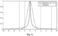
- sparsity In image processing applications of blind deconvolution, sparsity has been a popular regularization strategy to obtain meaningful solutions. However, sparsity assumption becomes too restrictive to model decaying nature of FBPs and often ignores the tail because of small coefficient values (close to zero). To counter this problem, the present disclosure also employs an exponential decaying kernel to model the tail and sparsity inducing prior constraints for initial few filter coefficients and a common delay.
- the present disclosure employs a non-informative flat prior on p (ek) and proceeds to the inference stage.
- Enforcing relevant prior distribution may not be enough to deal with the ill posed nature of the blind deconvolution problem, and discusses that the inference strategy to estimate the concerned parameters, should also be chosen with caution.
- the present disclosure employs an EM algorithm for inference and treat ek as parameters and f as the hidden random variable.
- the concerned posterior is computed, p ( f
- Equation (16) E is the stacked convolution matrix following Equation (10).
- the result from the E step is utilized to compute the Q function, which is essentially the conditional expectation of the complete data log likelihood with respect to the concerned posterior given in Equation (16).
- Q e k ⁇ c 1 c 2 E f
- the convolution matrix E in the update of f in Equation (17) will be constructed from the most recent estimates of the variant part.
- the convolution matrix F ⁇ is constructed using the recent estimate of f.
- These EM based updates are performed for a few iterations until a convergence criterion is satisfied.
- the present disclosure does not learn the noise variance ⁇ 2 in the M step. Instead an annealing type strategy is employed where after every iteration the noise variance, ⁇ 2 ⁇ ⁇ 2 / ⁇ , where ⁇ > 1 is updated until it reaches a prespecified minimum value ( ⁇ min ) .
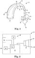
- FIGS. 1-2 are various views of one embodiment of a hearing assistance device 10.
- the device 10 can provide sound to an ear of a patient (not shown).
- the device 10 includes a housing 20 adapted to be worn on or behind the ear, hearing assistance components 60 enclosed in the housing, and an earmold 30 adapted to be worn in the ear.
- the device can also include a sound tube 40 adapted to transmit an acoustic output or sound from the housing 20 to the earmold 30, and an earhook 50 adapted to connect the housing to the sound tube.
- acoustic output means a measure of the intensity, pressure, or power generated by an ultrasonic transducer.
- the sound tube 40 can be integral with the earmold 30. Further, the earmold 30, sound tube 40, and earhook 50 can together provide an earpiece 12.
- the housing 20 can take any suitable shape or combination of shapes and have any suitable dimensions. In one or more embodiments, the housing 20 can take a shape that can conform to at least a portion of the ear of the patient. Further, the housing 20 can include any suitable material or combination of materials, e.g., silicone, urethane, acrylates, flexible epoxy, acrylated urethane, and combinations thereof.
- FIG. 2 is a schematic cross-section view of the housing 20 of device 10 of FIG. 1 .
- Hearing assistance components 60 are enclosed in the housing 20 and can include any suitable device or devices, e.g., integrated circuits, power sources, microphones, receivers, etc.
- the components 60 can include a processor 62, a microphone 64, a receiver 66 (e.g., speaker), a power source 68, and an antenna 70.
- the microphone 64, receiver 66, power source 68, and antenna 70 can be electrically connected to the processor 62 using any suitable technique or combination of techniques.
- any suitable processor 62 can be utilized with the hearing assistance device 10.
- the processor 62 can be adapted to employ programmable gains to adjust the hearing assistance device output to a patient's particular hearing impairment.
- the processor 62 can be a digital signal processor (DSP), microprocessor, microcontroller, other digital logic, or combinations thereof.
- DSP digital signal processor
- the processing can be done by a single processor, or can be distributed over different devices.
- the processing of signals referenced in this disclosure can be performed using the processor 62 or over different devices.
- the processor 62 is adapted to perform instructions stored in one or more memories 61.
- Various types of memory can be used, including volatile and nonvolatile forms of memory.
- the processor 62 or other processing devices execute instructions to perform a number of signal processing tasks. Such embodiments can include analog components in communication with the processor 62 to perform signal processing tasks, such as sound reception by the microphone 64, or playing of sound using the receiver 66.
- the hearing assistance components 60 can also include the microphone 64 that is electrically connected to the processor 62. Although one microphone 64 is depicted, the components 60 can include any suitable number of microphones. Further, the microphone 64 can be disposed in any suitable location within the housing 20. For example, in one or more embodiments, a port or opening can be formed in the housing 20, and the microphone 64 can be disposed adjacent the port to receive audio information from the patient's environment.
- any suitable microphone 64 can be utilized.
- the microphone 64 can be selected to detect one or more audio signals and convert such signals to an electrical signal that is provided to the processor.
- the processor 62 can include an analog-to-digital convertor that converts the electrical signal from the microphone 64 to a digital signal.
- the receiver 66 Electrically connected to the processor 62 is the receiver 66. Any suitable receiver can be utilized. In one or more embodiments, the receiver 66 can be adapted to convert an electrical signal from the processor 62 to an acoustic output or sound that can be transmitted from the housing 60 to the earmold 30 and provided to the patient. In one or more embodiments, the receiver 66 can be disposed adjacent an opening 24 disposed in a first end 22 of the housing 20. As used herein, the term "adjacent the opening" means that the receiver 66 is disposed closer to the opening 24 disposed in the first end 22 than to a second end 26 of the housing 20.
- the power source 68 is electrically connected to the processor 62 and is adapted to provide electrical energy to the processor and one or more of the other hearing assistance components 60.
- the power source 68 can include any suitable power source or power sources, e.g., a battery.
- the power source 68 can include a rechargeable battery.
- the components 60 can include two or more power sources 68.
- the components 60 can also include the optional antenna 70. Any suitable antenna or combination of antennas can be utilized.
- the antenna 70 can include one or more antennas having any suitable configuration. For example, antenna configurations can vary and can be included within the housing 20 or be external to the housing. Further, the antenna 70 can be compatible with any suitable protocol or combination of protocols.
- the components 60 can also include a transmitter that transmits electromagnetic signals and a radio-frequency receiver that receives electromagnetic signals using any suitable protocol or combination of protocols.
- the earmold 30 can include any suitable earmold and take any suitable shape or combination of shapes.
- the earmold 30 includes a body 32 and a sound hole 34 disposed in the body.
- the sound hole 34 can be disposed in any suitable location in the body 32 of the earmold 30.
- the sound hole 34 can be disposed in an upper portion 38 of the body 32 and extend through the body and to an opening (not shown) at a first end 36 of the body.
- the sound hole 34 can be adapted to transmit sound from the sound tube 40 through the body 32 of the earmold 30 such that the sound exits the opening at the first end 36 of the body and is, therefore, transmitted to the patient.
- the body 32 of the earmold 30 can take any suitable shape or combination of shapes.
- the body 32 takes a shape that is compatible with a portion or portions of the ear cavity of the patient.
- the first end 36 of the body 32 can be adapted to be inserted into the ear canal of the patient.
- the earmold 30 can include any suitable material or combination of materials, e.g., silicone, urethane, acrylates, flexible epoxy, acrylated urethane, and combinations thereof.
- the earmold 30 can be manufactured using any suitable technique or combination of techniques as is further described herein.
- the sound tube 40 can be adapted to transmit sound from the housing 20 to the earmold 30.
- sound can be provided by the receiver 66 and directed through the sound tube 40 to the earmold 30.
- Such acoustic output can then be directed by the earmold 30 through the sound hole 34 such that the acoustic output is directed through the opening at the first end 36 of the body 32 of the earmold and to the patient.
- the sound tube 40 can take any suitable shape or combination of shapes and have any suitable dimensions.
- the sound tube 40 has a substantially circular cross-section along a length of the sound tube.
- the cross-section of the sound tube 40 is constant in a direction along the length of the sound tube.
- the cross-section of the sound tube 40 varies in the direction along the length.
- an inner diameter of the sound tube 40 can have any suitable dimensions.
- the inner diameter of the sound tube 40 can be equal to at least .5 mm and no greater than 5 mm.
- the sound tube 40 can have any suitable length.
- the length of the sound tube 40 is at least 1 mm and no greater than 100 mm.
- the sound tube 40 can take any suitable shape or combination of shapes.
- the sound tube 40 can take a shape that is tailored to follow the anatomy of the patient's ear from the earmold 30 that is inserted at least partially within the inner canal of the patient, around a front edge of the pinna of the patient's ear, and to the earhook 50 of the device 10.
- one or both of the shape and dimension of the sound tube 40 can be tailored to a specific patient's anatomy.
- the sound tube 40 can be integral with the earhook 50.
- the sound tube 40 can include any suitable material or materials, e.g., the same materials utilized for the earmold 30. In one or more embodiments, the sound tube 40 can include a material or materials that are different from those of the earmold 30.
- the sound tube 40 can be connected to the earmold 30 using any suitable technique or combination of techniques.
- a first end 42 of the sound tube 40 is connected to the sound hole 34 of the earmold 30 by inserting the first end into the sound hole.
- the sound tube 40 is integral with the earmold 30 such that the first end 42 of the sound tube is aligned with and acoustically connected to the sound hole 34 of the earmold.
- acoustically connected means that two or more elements or components are connected such that acoustical information (e.g., acoustic output or sound) can be transmitted between the two or more elements or components.
- the sound tube 40 is integral with the earmold 30 such that sound can be transmitted between the sound tube and earmold.
- the sound tube 40 can be directly connected to the housing 20 such that the sound tube acoustically connects the housing to the earmold 30.
- the device 10 can include the earhook 50 that is adapted to connect the housing 20 to the sound tube 40. Any suitable earhook 50 can be utilized with the device 10. Further, the earhook 50 can have any suitable dimensions and take any suitable shape or combination of shapes. In one or more embodiments, the earhook 50 takes a curved shape such that the earhook follows the forward or front edge of the pinna of the patient's year.
- the earhook 50 can include any suitable material or materials, e.g., the same materials utilized for the earmold 30. In one or more embodiments, the earhook 50 can include a material or materials that are different from the materials utilized for the earmold 30. Further, for example, the earhook 50 can include a material or materials that are the same as or different from the materials utilized for the sound tube 40.
- the earhook 50 can be connected to the sound tube 40 using any suitable technique or combination of techniques.
- a second end 54 of the earhook 50 is connected to a second end 44 of the sound tube 40 using any suitable technique or combination of techniques.
- the second end 54 of the earhook 50 is friction fit either over or within the second end 44 of the sound tube 40.
- the earhook 50 can be connected to the housing 20 using any suitable technique or combination of techniques.
- the earhook 50 can include one or more threaded grooves disposed on an inner surface of the first end 52 of the earhook that can be threaded onto threaded grooves formed on the first end 22 of the housing 20.
- the device 10 can also include an extension tube (not shown) that connects the sound tube 40 to the earhook 50. Any suitable extension tube can be utilized. In one or more embodiments, the extension tube acoustically connects the sound tube 40 to the earhook 50.
- the earmold 30, sound tube 40, and earhook 50 can, in one or more embodiments, provide the earpiece 12.
- two or more of the earmold 30, sound tube 40, and earhook 50 can be integral.
- the earhook 50 is integral with the sound tube 40, e.g., the second end 54 of the earhook is integral with the second end 44 of the sound tube.
- the sound tube 40 can be integral with the earmold 30, e.g., the first end 42 of the sound tube can be integral with the earmold.
- the hearing assistance device 10 can include an optional coating disposed on one or more of the housing 20, earmold 30, sound tube 40, and earhook 50. Further, the coating can include any suitable material or materials.
- the coating can provide various desired properties.
- the coating can include a hydrophobic, hydrophilic, oleophobic, or oleophilic material.
- the optional coating can include a textured coating to provide the patient with one or more gripping surfaces such that the patient can more easily grasp a portion or portions of the earpiece 12 and dispose the earmold 30 within the ear cavity.
- the device 10 of FIGS. 1-2 can be manufactured using any suitable technique or combination of techniques.
- forming of the hearing assistance device 10 may include forming a three-dimensional model of an ear cavity of the patient.
- the ear cavity can include any suitable portion of the ear canal, e.g., the entire ear canal.
- the ear cavity can include any suitable portion of the pinna.
- Any suitable technique or combination of techniques can be utilized to form the three-dimensional model of the ear cavity of the patient.
- a mold of the ear cavity can be taken using any suitable technique or combination of techniques. Such mold can then be scanned using any suitable technique or combination of techniques to provide a digital representation of the mold.
- the ear cavity of the patient can be scanned using any suitable technique or combination of techniques to provide a three-dimensional digital representation of the ear cavity without the need for a physical mold of the ear cavity.
- a three-dimensional model of the earmold 30 based upon the three-dimensional model of the ear cavity of the patient can be formed. Any suitable technique or combination of techniques can be utilized to form the three-dimensional model of the earmold 30.
- a three-dimensional model of the sound tube 40 can be formed using any suitable technique or combination of techniques.
- the three-dimensional model of the sound tube 40 can be added to the three-dimensional model of the earmold 30 such that that the sound tube model and the earmold model are integral.
- the three-dimensional model of the sound tube 40 is aligned with the sound hole 34 of the three-dimensional model of the earmold 30.
- the completed earpiece 12 can be connected to the housing 20 by connecting the first end 52 of the earhook 50 to the first end 22 of the housing 20 of the device 10 using any suitable technique or combination of techniques.
- FIG. 3 is a schematic diagram of filtering of a feedback signal in a hearing assistance device according to an embodiment of the present disclosure.
- offline processing by a processor is used to measure L number of feedback signals from L feedback paths for a specific user, wearing the same hearing assistance device 10 but in L different acoustic environments, Block 70.
- Offline processing of the acoustic signals of the L feedback paths is used to determine a common or invariant portion using Bayesian Blind Deconvolution (BBD), Block 72, described below in detail.
- BBD Bayesian Blind Deconvolution
- the determined common portion is stored in processor 61 of device 10 and used as a filter 74 to extract the unwanted feedback signal from the audio output by the device 61 for runtime feedback cancellation.
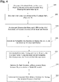
- FIG. 4 is a flowchart of a method of determining filtering of a feedback signal in a hearing assistance device according to an embodiment of the present disclosure.
- the processor uses the L feedback path measurements associated with the device 10, Block 100.
- the processor determines a model of the L feedback paths, using Equation (2) as described above, with the model including an invariant portion and a time varying portion, Block 102, and analyzes and observes the L feedback path measurements and determines a probable structure of the invariant portion, Block 104, to generate a structural constraint, which can be imposed during the estimation stage to deal with the problem of there being an infinite number of possible solutions for the invariant portion.
- FIG. 5 is a plot of signals from four training feedback paths over time to illustrate an example of extracting an invariant portion according to an embodiment of the present disclosure.
- the processor identifies certain common empirical or structural observations of feedback signals 120 associated with a predetermined number of the L feedback paths, such as there being a delay 122 in each of the feedback signals, or there being a certain decay 124 associated with the feedback signals for the predetermined feedback paths, or there being portions of the signals that are similar, such as the portion between 10 and 30 taps.
- the empirical observations reduce the number of possible solutions for determining the possible structure of the invariant portion, and the extracted common portion from the training feedback paths is then used to model the unseen test feedback path, as described below.
- the processor determines probability distributions to impose the structural constraint on the invariant portion, Block 106, with all other required probability distributions (such as likelihood) to characterize the Bayesian Model, using Equations (12), (13), and (10) as described above, and iteratively determines, during an iterative process, the invariant portion using the determined probability distributions and the feedback path measurements, Block 108.
- the processor develops an Expectation Maximization (EM) based iterative algorithm, which maximizes the posterior distribution (seeks MAP estimate) to estimate the common/invariant portion, using Equations (16) - (25) described above.
- EM Expectation Maximization
- the processor updates, for each iteration, a measurement noise variance representative of model mismatch, to reduce a probability of a suboptimal, or non-desirable determination of an invariant filter, Block 110.
- a measurement noise variance representative of model mismatch For example, during iterative updates of the EM algorithm, an annealing strategy may be employed to reduce uncertainty of the underlying model over iterations, which in turn prevents the algorithm from getting stuck to a local minimum.
- the processor determines the invariant filter in response to a criterion for ending the iterative process being satisfied, Block 112. For example, after a predetermined number of iterations, or any other meaningful stopping criteria, the EM algorithm may be stopped, and the point estimate of the common portion becomes the invariant filter, which is then sent to the device 10 for run time feedback cancellation.
Landscapes
- Health & Medical Sciences (AREA)
- General Health & Medical Sciences (AREA)
- Neurosurgery (AREA)
- Otolaryngology (AREA)
- Physics & Mathematics (AREA)
- Engineering & Computer Science (AREA)
- Acoustics & Sound (AREA)
- Signal Processing (AREA)
- Circuit For Audible Band Transducer (AREA)
Claims (13)
- Verfahren zum Bestimmen eines Filters, um Rückkopplungssignale von Eingangssignalen in einer Hörunterstützungsvorrichtung (10) zu beenden, umfassend:Messen (100) von Rückkopplungssignalen für eine zuvor bestimmte Anzahl von Rückkopplungspfaden einer Vielzahl von Rückkopplungspfaden, die der Vorrichtung (10) zugeordnet sind;Bestimmen (102) eines Modells der zuvor bestimmten Anzahl von Rückkopplungspfaden, das Modell umfassend einen unveränderlichen Abschnitt und einen zeitveränderlichen Abschnitt, wobei der unveränderliche Abschnitt umfassend ein Filter mit endlicher Impulsantwort (finite impulse response filter - FIR) (74) und der zeitveränderliche Abschnitt umfassend ein adaptives FIR-Filter;Bestimmen (104) einer Struktur des unveränderlichen Abschnitts, um eine strukturelle Beschränkung zu erzeugen, um die zuvor bestimmte Anzahl von Rückkopplungspfaden zu beschränken, basierend auf dem Bestimmen von empirischen Merkmalen der zuvor bestimmten Anzahl von Rückkopplungspfaden, wobei die empirischen Merkmale eine Verzögerung, die dem unveränderlichen Abschnitt der zuvor bestimmten Anzahl von Rückkopplungspfaden zugeordnet ist, eine geringe Dichte von Filterkoeffizienten eines frühen Teils des unveränderlichen Abschnitts und einen exponentiellen Abfall eines Filterendes umfassen, der dem unveränderlichen Abschnitt der zuvor bestimmten Anzahl von Rückkopplungspfaden zugeordnet ist;Bestimmen (106) einer vorherigen Wahrscheinlichkeitsverteilung basierend auf einer Gaußschen Verteilung, um dem unveränderlichen Abschnitt die strukturelle Beschränkung aufzuerlegen;iteratives Bestimmen (108), während eines iterativen Prozesses basierend auf einer Erwartungsmaximierung, des unveränderlichen Abschnitts unter Verwendung der bestimmten vorherigen Wahrscheinlichkeitsverteilung und der Rückkopplungspfadmessungen;Aktualisieren (110), für jede Iteration, einer Messrauschvarianz, die eine Modellfehlanpassung darstellt, um eine Wahrscheinlichkeit einer nicht erwünschten Bestimmung des FIR-Filters (74) des unveränderlichen Abschnitts zu verringern; undBestimmen (112) des FIR-Filters (74) des unveränderlichen Abschnitts als Reaktion darauf, dass ein Kriterium zum Abschließen des iterativen Prozesses erfüllt ist, wobei das bestimmte FIR-Filter (74) des unveränderlichen Abschnitts durch die Hörunterstützungsvorrichtung verwendet wird, um Rückkopplungssignale von dem Ausgang der Hörunterstützungsvorrichtung für einen Eingang in das adaptive FIR-Filter des zeitveränderlichen Abschnitts zum Beenden von Rückkopplungssignalen aus den Eingangssignalen zu extrahieren.
- Verfahren nach Anspruch 1, ferner umfassend ein Anwenden der auf Gauß basierenden vorherigen Wahrscheinlichkeitsverteilung, um einer zuvor bestimmten Anzahl von Filterkoeffizienten des FIR-Filters des unveränderlichen Abschnitts die Beschränkung aufzuerlegen.
- Verfahren nach Anspruch 2, ferner umfassend das Auferlegen des exponentiellen Abfalls durch Parametrisieren späterer Elemente einer Kovarianzmatrix der auf Gauß basierenden vorherigen Wahrscheinlichkeitsverteilung, die den Endkoeffizienten des FIR-Filters des unveränderlichen Abschnitts zugeordnet ist.
- Verfahren nach Anspruch 3, wobei das Parametrisieren späterer Elemente einer Kovarianzmatrix, die den Endkoeffizienten des FIR-Filters des unveränderlichen Abschnitts zugeordnet ist, das Anwenden der Hyperparameter γ , c1 und c2 von p(f|γ,c1 , c2 )∼N(0,┌) umfasst, wobei γ =[γ1, ..., γp] und N eine Gaußsche Verteilung bezeichnet, mit der Kovarianzmatrix Γ = diag[γ 1, ..., γP, c1e-C2, ..., c 1 e-C2m, ..., c 1 e- C2M ], wobei P die Anzahl der anfänglichen Abgriffe ist und f das FIR-Filter des unveränderlichen Abschnitts ist.
- Verfahren nach Anspruch 1, wobei das Aktualisieren, für jede Iteration, einer Messrauschvarianz, die eine Modellfehlanpassung darstellt, ein Nutzen einer simulierten Glühstrategie umfasst, um eine Konvergenz zu einem globalen Optima zu erreichen.
- Verfahren nach Anspruch 5, wobei ein Wert der Modellfehlanpassung unter Verwendung von

- Verfahren nach Anspruch 1, wobei das Kriterium zum Abschließen des iterativen Prozesses eine zuvor bestimmte Anzahl von Iterationen umfasst, die vor dem Bestimmen des FIR-Filters des unveränderlichen Abschnitts durchgeführt werden.
- System zum Bestimmen eines Filters, um Rückkopplungssignale von Eingangssignalen zu beenden, das System umfassend:eine Hörunterstützungsvorrichtung (10) zum Verarbeiten von akustischen Signalen; undeinen Prozessor, der für Folgendes konfiguriert ist:Messen (100) von Rückkopplungssignalen für eine zuvor bestimmte Anzahl von Rückkopplungspfaden einer Vielzahl von Rückkopplungspfaden, die der Vorrichtung (10) zugeordnet sind;Bestimmen (102) eines Modells der zuvor bestimmten Anzahl von Rückkopplungspfaden, das Modell umfassend einen unveränderlichen Abschnitt und einen zeitveränderlichen Abschnitt, wobei der unveränderliche Abschnitt umfassend ein Filter mit endlicher Impulsantwort (FIR) (74) und der zeitveränderliche Abschnitt umfassend ein adaptives FIR-Filter;Bestimmen (104) einer Struktur des unveränderlichen Abschnitts, um eine strukturelle Beschränkung zu erzeugen, um die zuvor bestimmte Anzahl von Rückkopplungspfaden zu beschränken, basierend auf dem Bestimmen von empirischen Merkmalen der zuvor bestimmten Anzahl von Rückkopplungspfaden, wobei die empirischen Merkmale eine Verzögerung, die dem unveränderlichen Abschnitt der zuvor bestimmten Anzahl von Rückkopplungspfaden zugeordnet ist, eine geringe Dichte von Filterkoeffizienten eines frühen Teils des unveränderlichen Abschnitts und einen exponentiellen Abfall eines Filterendes umfassen, der dem unveränderlichen Abschnitt der zuvor bestimmten Anzahl von Rückkopplungspfaden zugeordnet ist;Bestimmen (106) einer vorherigen Wahrscheinlichkeitsverteilung, um dem unveränderlichen Abschnitt die strukturelle Beschränkung aufzuerlegen;iteratives Bestimmen (108), während eines iterativen Prozesses basierend auf einer Erwartungsmaximierung, des unveränderlichen Abschnitts unter Verwendung der bestimmten vorherigen Wahrscheinlichkeitsverteilung und der Rückkopplungspfadmessungen;Aktualisieren (110), für jede Iteration, einer Messrauschvarianz, die eine Modellfehlanpassung darstellt, um eine Wahrscheinlichkeit einer nicht erwünschten Bestimmung des FIR-Filters (74) des unveränderlichen Abschnitts zu verringern; undBestimmen (112) des FIR-Filters (74) des unveränderlichen Abschnitts als Reaktion darauf, dass ein Kriterium zum Abschließen des iterativen Prozesses erfüllt ist, wobei das bestimmte FIR-Filter (74) des unveränderlichen Abschnitts durch die Hörunterstützungsvorrichtung verwendet wird, um Rückkopplungssignale von dem Ausgang der Hörunterstützungsvorrichtung für einen Eingang in das adaptive FIR-Filter des zeitveränderlichen Abschnitts zum Beenden von Rückkopplungssignalen aus den Eingangssignalen zu extrahieren.
- System nach Anspruch 8, wobei der Prozessor konfiguriert ist, um die auf Gauß basierende vorherige Wahrscheinlichkeitsverteilung anzuwenden, um einer zuvor bestimmten Anzahl von Filterkoeffizienten des FIR-Filters des unveränderlichen Abschnitts die Beschränkung aufzuerlegen.
- System nach Anspruch 9, wobei der Prozessor konfiguriert ist, um den exponentiellen Abfall durch Parametrisieren späterer Elemente einer Kovarianzmatrix aufzuerlegen, die den Endkoeffizienten des FIR-Filters des unveränderlichen Abschnitts zugeordnet ist.
- System nach Anspruch 10, wobei das Parametrisieren späterer Elemente einer Kovarianzmatrix, die den Endkoeffizienten des FIR-Filters des unveränderlichen Abschnitts zugeordnet ist, das Anwenden der Hyperparameter γ , c1 und c2 von p(f|γ,c1, c2 )∼N(0,┌) umfasst, wobei γ =[γ1, ..., γP] und N eine Gaußsche Verteilung bezeichnet, mit der Kovarianzmatrix Γ = diag[γ 1, ..., γP, c 1 e-C2, ..., c 1e- C2m , ..., c 1e- C2M ], wobei P die Anzahl der anfänglichen Abgriffe ist und f das FIR-Filter des unveränderlichen Abschnitts ist.
- System nach Anspruch 8, wobei das Aktualisieren, für jede Iteration, einer Messrauschvarianz, die eine Modellfehlanpassung darstellt, das Nutzen einer simulierten Glühstrategie umfasst, um eine Konvergenz zu einem globalen Optima zu erreichen.
- System nach Anspruch 12, wobei ein Wert der Modellfehlanpassung unter Verwendung von

Applications Claiming Priority (2)
| Application Number | Priority Date | Filing Date | Title |
|---|---|---|---|
| US201662393452P | 2016-09-12 | 2016-09-12 | |
| PCT/US2017/051187 WO2018049405A1 (en) | 2016-09-12 | 2017-09-12 | Accoustic feedback path modeling for hearing assistance device |
Publications (2)
| Publication Number | Publication Date |
|---|---|
| EP3510795A1 EP3510795A1 (de) | 2019-07-17 |
| EP3510795B1 true EP3510795B1 (de) | 2022-10-19 |
Family
ID=59966856
Family Applications (1)
| Application Number | Title | Priority Date | Filing Date |
|---|---|---|---|
| EP17772548.8A Active EP3510795B1 (de) | 2016-09-12 | 2017-09-12 | Pfadmodellierung von akustischem feedback für hörgerät |
Country Status (3)
| Country | Link |
|---|---|
| US (1) | US11140499B2 (de) |
| EP (1) | EP3510795B1 (de) |
| WO (1) | WO2018049405A1 (de) |
Family Cites Families (2)
| Publication number | Priority date | Publication date | Assignee | Title |
|---|---|---|---|---|
| US6072884A (en) | 1997-11-18 | 2000-06-06 | Audiologic Hearing Systems Lp | Feedback cancellation apparatus and methods |
| EP3148213B1 (de) | 2015-09-25 | 2018-09-12 | Starkey Laboratories, Inc. | Dynamische relative transferfunktionsschätzung mit strukturiertem verstreutem bayesschem lernen |
-
2017
- 2017-09-12 EP EP17772548.8A patent/EP3510795B1/de active Active
- 2017-09-12 WO PCT/US2017/051187 patent/WO2018049405A1/en not_active Ceased
- 2017-09-12 US US16/332,437 patent/US11140499B2/en active Active
Also Published As
| Publication number | Publication date |
|---|---|
| US20210144494A1 (en) | 2021-05-13 |
| WO2018049405A9 (en) | 2018-05-11 |
| WO2018049405A1 (en) | 2018-03-15 |
| EP3510795A1 (de) | 2019-07-17 |
| US11140499B2 (en) | 2021-10-05 |
Similar Documents
| Publication | Publication Date | Title |
|---|---|---|
| US12236968B2 (en) | Ear-worn electronic device incorporating annoyance model driven selective active noise control | |
| US10242657B2 (en) | Snoring active noise-cancellation, masking, and suppression | |
| US9838804B2 (en) | Methods, systems, and devices for adaptively filtering audio signals | |
| JP6554188B2 (ja) | 補聴器システムの動作方法および補聴器システム | |
| CN104902418A (zh) | 用于估计目标和噪声谱方差的多传声器方法 | |
| CN110402540A (zh) | 主动降噪方法、装置、芯片、主动控制系统和存储介质 | |
| EP4252434B1 (de) | Vorrichtung und verfahren zus schätzung des schalldrucks am trommelfell mittels sekundärpfad-messung | |
| CN112309362A (zh) | Mr系统的主动声学降噪方法、装置和计算机设备 | |
| CN110115049A (zh) | 基于记录对象声音的声音信号建模 | |
| EP3510795B1 (de) | Pfadmodellierung von akustischem feedback für hörgerät | |
| CN105430586A (zh) | 用于反馈抑制的方法和装置 | |
| US12413916B2 (en) | Apparatus and method for speech enhancement and feedback cancellation using a neural network | |
| Giri et al. | Bayesian blind deconvolution with application to acoustic feedback path modeling | |
| Hashemgeloogerdi et al. | Adaptive feedback cancellation in hearing aids based on orthonormal basis functions with prediction-error method based prewhitening | |
| US20250182772A1 (en) | Audio enhancement method and apparatus, and computer storage medium | |
| CN105744456A (zh) | 数字助听器自适应声反馈消除方法 | |
| CN113132847B (zh) | 主动降噪耳机的降噪参数确定方法及装置、主动降噪方法 | |
| CN117238269A (zh) | 一种主动噪声控制方法、装置、介质 | |
| Ma et al. | Extracting the invariant model from the feedback paths of digital hearing aids | |
| Schepker et al. | Individualized sound pressure equalization in hearing devices exploiting an electro-acoustic model | |
| US20260052351A1 (en) | Apparatus and method for speech enhancement and feedback cancellation using a neural network | |
| Hilgemann et al. | Design of low-order IIR filters based on Hankel nuclear norm regularization for achieving acoustic transparency | |
| Deka et al. | Hard Thresholding Algorithm for Adaptive Feedback Cancellation in Single Microphone Hearing Aids | |
| EP4287659B1 (de) | Vorhersage der verstärkungsreserve in einem hörgerät mit einem neuronalen netzwerk | |
| Firoozabadi et al. | Multi-speaker localization by central and lateral microphone arrays based on the combination of 2D-SRP and subband GEVD algorithms |
Legal Events
| Date | Code | Title | Description |
|---|---|---|---|
| STAA | Information on the status of an ep patent application or granted ep patent |
Free format text: STATUS: UNKNOWN |
|
| STAA | Information on the status of an ep patent application or granted ep patent |
Free format text: STATUS: THE INTERNATIONAL PUBLICATION HAS BEEN MADE |
|
| PUAI | Public reference made under article 153(3) epc to a published international application that has entered the european phase |
Free format text: ORIGINAL CODE: 0009012 |
|
| STAA | Information on the status of an ep patent application or granted ep patent |
Free format text: STATUS: REQUEST FOR EXAMINATION WAS MADE |
|
| 17P | Request for examination filed |
Effective date: 20190410 |
|
| AK | Designated contracting states |
Kind code of ref document: A1 Designated state(s): AL AT BE BG CH CY CZ DE DK EE ES FI FR GB GR HR HU IE IS IT LI LT LU LV MC MK MT NL NO PL PT RO RS SE SI SK SM TR |
|
| AX | Request for extension of the european patent |
Extension state: BA ME |
|
| DAV | Request for validation of the european patent (deleted) | ||
| DAX | Request for extension of the european patent (deleted) | ||
| STAA | Information on the status of an ep patent application or granted ep patent |
Free format text: STATUS: EXAMINATION IS IN PROGRESS |
|
| 17Q | First examination report despatched |
Effective date: 20201117 |
|
| GRAP | Despatch of communication of intention to grant a patent |
Free format text: ORIGINAL CODE: EPIDOSNIGR1 |
|
| STAA | Information on the status of an ep patent application or granted ep patent |
Free format text: STATUS: GRANT OF PATENT IS INTENDED |
|
| INTG | Intention to grant announced |
Effective date: 20220413 |
|
| RIN1 | Information on inventor provided before grant (corrected) |
Inventor name: ZHANG, TAO Inventor name: MUSTIERE, FRED Inventor name: GIRI, RITWIK |
|
| GRAS | Grant fee paid |
Free format text: ORIGINAL CODE: EPIDOSNIGR3 |
|
| GRAA | (expected) grant |
Free format text: ORIGINAL CODE: 0009210 |
|
| STAA | Information on the status of an ep patent application or granted ep patent |
Free format text: STATUS: THE PATENT HAS BEEN GRANTED |
|
| AK | Designated contracting states |
Kind code of ref document: B1 Designated state(s): AL AT BE BG CH CY CZ DE DK EE ES FI FR GB GR HR HU IE IS IT LI LT LU LV MC MK MT NL NO PL PT RO RS SE SI SK SM TR |
|
| REG | Reference to a national code |
Ref country code: GB Ref legal event code: FG4D |
|
| REG | Reference to a national code |
Ref country code: CH Ref legal event code: EP |
|
| REG | Reference to a national code |
Ref country code: DE Ref legal event code: R096 Ref document number: 602017062799 Country of ref document: DE |
|
| REG | Reference to a national code |
Ref country code: IE Ref legal event code: FG4D |
|
| REG | Reference to a national code |
Ref country code: AT Ref legal event code: REF Ref document number: 1526304 Country of ref document: AT Kind code of ref document: T Effective date: 20221115 |
|
| REG | Reference to a national code |
Ref country code: LT Ref legal event code: MG9D |
|
| REG | Reference to a national code |
Ref country code: NL Ref legal event code: MP Effective date: 20221019 |
|
| REG | Reference to a national code |
Ref country code: AT Ref legal event code: MK05 Ref document number: 1526304 Country of ref document: AT Kind code of ref document: T Effective date: 20221019 |
|
| PG25 | Lapsed in a contracting state [announced via postgrant information from national office to epo] |
Ref country code: NL Free format text: LAPSE BECAUSE OF FAILURE TO SUBMIT A TRANSLATION OF THE DESCRIPTION OR TO PAY THE FEE WITHIN THE PRESCRIBED TIME-LIMIT Effective date: 20221019 |
|
| PG25 | Lapsed in a contracting state [announced via postgrant information from national office to epo] |
Ref country code: SE Free format text: LAPSE BECAUSE OF FAILURE TO SUBMIT A TRANSLATION OF THE DESCRIPTION OR TO PAY THE FEE WITHIN THE PRESCRIBED TIME-LIMIT Effective date: 20221019 Ref country code: PT Free format text: LAPSE BECAUSE OF FAILURE TO SUBMIT A TRANSLATION OF THE DESCRIPTION OR TO PAY THE FEE WITHIN THE PRESCRIBED TIME-LIMIT Effective date: 20230220 Ref country code: NO Free format text: LAPSE BECAUSE OF FAILURE TO SUBMIT A TRANSLATION OF THE DESCRIPTION OR TO PAY THE FEE WITHIN THE PRESCRIBED TIME-LIMIT Effective date: 20230119 Ref country code: LT Free format text: LAPSE BECAUSE OF FAILURE TO SUBMIT A TRANSLATION OF THE DESCRIPTION OR TO PAY THE FEE WITHIN THE PRESCRIBED TIME-LIMIT Effective date: 20221019 Ref country code: FI Free format text: LAPSE BECAUSE OF FAILURE TO SUBMIT A TRANSLATION OF THE DESCRIPTION OR TO PAY THE FEE WITHIN THE PRESCRIBED TIME-LIMIT Effective date: 20221019 Ref country code: ES Free format text: LAPSE BECAUSE OF FAILURE TO SUBMIT A TRANSLATION OF THE DESCRIPTION OR TO PAY THE FEE WITHIN THE PRESCRIBED TIME-LIMIT Effective date: 20221019 Ref country code: AT Free format text: LAPSE BECAUSE OF FAILURE TO SUBMIT A TRANSLATION OF THE DESCRIPTION OR TO PAY THE FEE WITHIN THE PRESCRIBED TIME-LIMIT Effective date: 20221019 |
|
| PG25 | Lapsed in a contracting state [announced via postgrant information from national office to epo] |
Ref country code: RS Free format text: LAPSE BECAUSE OF FAILURE TO SUBMIT A TRANSLATION OF THE DESCRIPTION OR TO PAY THE FEE WITHIN THE PRESCRIBED TIME-LIMIT Effective date: 20221019 Ref country code: PL Free format text: LAPSE BECAUSE OF FAILURE TO SUBMIT A TRANSLATION OF THE DESCRIPTION OR TO PAY THE FEE WITHIN THE PRESCRIBED TIME-LIMIT Effective date: 20221019 Ref country code: LV Free format text: LAPSE BECAUSE OF FAILURE TO SUBMIT A TRANSLATION OF THE DESCRIPTION OR TO PAY THE FEE WITHIN THE PRESCRIBED TIME-LIMIT Effective date: 20221019 Ref country code: IS Free format text: LAPSE BECAUSE OF FAILURE TO SUBMIT A TRANSLATION OF THE DESCRIPTION OR TO PAY THE FEE WITHIN THE PRESCRIBED TIME-LIMIT Effective date: 20230219 Ref country code: HR Free format text: LAPSE BECAUSE OF FAILURE TO SUBMIT A TRANSLATION OF THE DESCRIPTION OR TO PAY THE FEE WITHIN THE PRESCRIBED TIME-LIMIT Effective date: 20221019 Ref country code: GR Free format text: LAPSE BECAUSE OF FAILURE TO SUBMIT A TRANSLATION OF THE DESCRIPTION OR TO PAY THE FEE WITHIN THE PRESCRIBED TIME-LIMIT Effective date: 20230120 |
|
| REG | Reference to a national code |
Ref country code: DE Ref legal event code: R097 Ref document number: 602017062799 Country of ref document: DE |
|
| PG25 | Lapsed in a contracting state [announced via postgrant information from national office to epo] |
Ref country code: SM Free format text: LAPSE BECAUSE OF FAILURE TO SUBMIT A TRANSLATION OF THE DESCRIPTION OR TO PAY THE FEE WITHIN THE PRESCRIBED TIME-LIMIT Effective date: 20221019 Ref country code: RO Free format text: LAPSE BECAUSE OF FAILURE TO SUBMIT A TRANSLATION OF THE DESCRIPTION OR TO PAY THE FEE WITHIN THE PRESCRIBED TIME-LIMIT Effective date: 20221019 Ref country code: EE Free format text: LAPSE BECAUSE OF FAILURE TO SUBMIT A TRANSLATION OF THE DESCRIPTION OR TO PAY THE FEE WITHIN THE PRESCRIBED TIME-LIMIT Effective date: 20221019 Ref country code: DK Free format text: LAPSE BECAUSE OF FAILURE TO SUBMIT A TRANSLATION OF THE DESCRIPTION OR TO PAY THE FEE WITHIN THE PRESCRIBED TIME-LIMIT Effective date: 20221019 Ref country code: CZ Free format text: LAPSE BECAUSE OF FAILURE TO SUBMIT A TRANSLATION OF THE DESCRIPTION OR TO PAY THE FEE WITHIN THE PRESCRIBED TIME-LIMIT Effective date: 20221019 |
|
| P01 | Opt-out of the competence of the unified patent court (upc) registered |
Effective date: 20230624 |
|
| PLBE | No opposition filed within time limit |
Free format text: ORIGINAL CODE: 0009261 |
|
| STAA | Information on the status of an ep patent application or granted ep patent |
Free format text: STATUS: NO OPPOSITION FILED WITHIN TIME LIMIT |
|
| PG25 | Lapsed in a contracting state [announced via postgrant information from national office to epo] |
Ref country code: SK Free format text: LAPSE BECAUSE OF FAILURE TO SUBMIT A TRANSLATION OF THE DESCRIPTION OR TO PAY THE FEE WITHIN THE PRESCRIBED TIME-LIMIT Effective date: 20221019 Ref country code: AL Free format text: LAPSE BECAUSE OF FAILURE TO SUBMIT A TRANSLATION OF THE DESCRIPTION OR TO PAY THE FEE WITHIN THE PRESCRIBED TIME-LIMIT Effective date: 20221019 |
|
| 26N | No opposition filed |
Effective date: 20230720 |
|
| PGFP | Annual fee paid to national office [announced via postgrant information from national office to epo] |
Ref country code: GB Payment date: 20230822 Year of fee payment: 7 |
|
| PG25 | Lapsed in a contracting state [announced via postgrant information from national office to epo] |
Ref country code: SI Free format text: LAPSE BECAUSE OF FAILURE TO SUBMIT A TRANSLATION OF THE DESCRIPTION OR TO PAY THE FEE WITHIN THE PRESCRIBED TIME-LIMIT Effective date: 20221019 |
|
| REG | Reference to a national code |
Ref country code: CH Ref legal event code: PL |
|
| PG25 | Lapsed in a contracting state [announced via postgrant information from national office to epo] |
Ref country code: LU Free format text: LAPSE BECAUSE OF NON-PAYMENT OF DUE FEES Effective date: 20230912 |
|
| REG | Reference to a national code |
Ref country code: BE Ref legal event code: MM Effective date: 20230930 |
|
| PG25 | Lapsed in a contracting state [announced via postgrant information from national office to epo] |
Ref country code: LU Free format text: LAPSE BECAUSE OF NON-PAYMENT OF DUE FEES Effective date: 20230912 Ref country code: IT Free format text: LAPSE BECAUSE OF FAILURE TO SUBMIT A TRANSLATION OF THE DESCRIPTION OR TO PAY THE FEE WITHIN THE PRESCRIBED TIME-LIMIT Effective date: 20221019 Ref country code: MC Free format text: LAPSE BECAUSE OF FAILURE TO SUBMIT A TRANSLATION OF THE DESCRIPTION OR TO PAY THE FEE WITHIN THE PRESCRIBED TIME-LIMIT Effective date: 20221019 |
|
| REG | Reference to a national code |
Ref country code: IE Ref legal event code: MM4A |
|
| PG25 | Lapsed in a contracting state [announced via postgrant information from national office to epo] |
Ref country code: IE Free format text: LAPSE BECAUSE OF NON-PAYMENT OF DUE FEES Effective date: 20230912 |
|
| PG25 | Lapsed in a contracting state [announced via postgrant information from national office to epo] |
Ref country code: CH Free format text: LAPSE BECAUSE OF NON-PAYMENT OF DUE FEES Effective date: 20230930 |
|
| PG25 | Lapsed in a contracting state [announced via postgrant information from national office to epo] |
Ref country code: IE Free format text: LAPSE BECAUSE OF NON-PAYMENT OF DUE FEES Effective date: 20230912 Ref country code: CH Free format text: LAPSE BECAUSE OF NON-PAYMENT OF DUE FEES Effective date: 20230930 |
|
| PG25 | Lapsed in a contracting state [announced via postgrant information from national office to epo] |
Ref country code: BE Free format text: LAPSE BECAUSE OF NON-PAYMENT OF DUE FEES Effective date: 20230930 |
|
| PG25 | Lapsed in a contracting state [announced via postgrant information from national office to epo] |
Ref country code: BG Free format text: LAPSE BECAUSE OF FAILURE TO SUBMIT A TRANSLATION OF THE DESCRIPTION OR TO PAY THE FEE WITHIN THE PRESCRIBED TIME-LIMIT Effective date: 20221019 |
|
| PG25 | Lapsed in a contracting state [announced via postgrant information from national office to epo] |
Ref country code: BG Free format text: LAPSE BECAUSE OF FAILURE TO SUBMIT A TRANSLATION OF THE DESCRIPTION OR TO PAY THE FEE WITHIN THE PRESCRIBED TIME-LIMIT Effective date: 20221019 |
|
| GBPC | Gb: european patent ceased through non-payment of renewal fee |
Effective date: 20240912 |
|
| PG25 | Lapsed in a contracting state [announced via postgrant information from national office to epo] |
Ref country code: GB Free format text: LAPSE BECAUSE OF NON-PAYMENT OF DUE FEES Effective date: 20240912 |
|
| PG25 | Lapsed in a contracting state [announced via postgrant information from national office to epo] |
Ref country code: CY Free format text: LAPSE BECAUSE OF FAILURE TO SUBMIT A TRANSLATION OF THE DESCRIPTION OR TO PAY THE FEE WITHIN THE PRESCRIBED TIME-LIMIT; INVALID AB INITIO Effective date: 20170912 |
|
| PG25 | Lapsed in a contracting state [announced via postgrant information from national office to epo] |
Ref country code: HU Free format text: LAPSE BECAUSE OF FAILURE TO SUBMIT A TRANSLATION OF THE DESCRIPTION OR TO PAY THE FEE WITHIN THE PRESCRIBED TIME-LIMIT; INVALID AB INITIO Effective date: 20170912 |
|
| PGFP | Annual fee paid to national office [announced via postgrant information from national office to epo] |
Ref country code: DE Payment date: 20250819 Year of fee payment: 9 |
|
| PGFP | Annual fee paid to national office [announced via postgrant information from national office to epo] |
Ref country code: FR Payment date: 20250909 Year of fee payment: 9 |
|
| PG25 | Lapsed in a contracting state [announced via postgrant information from national office to epo] |
Ref country code: TR Free format text: LAPSE BECAUSE OF FAILURE TO SUBMIT A TRANSLATION OF THE DESCRIPTION OR TO PAY THE FEE WITHIN THE PRESCRIBED TIME-LIMIT Effective date: 20221019 |