EP3510759B1 - Media ramp with film - Google Patents
Media ramp with film Download PDFInfo
- Publication number
- EP3510759B1 EP3510759B1 EP16915909.2A EP16915909A EP3510759B1 EP 3510759 B1 EP3510759 B1 EP 3510759B1 EP 16915909 A EP16915909 A EP 16915909A EP 3510759 B1 EP3510759 B1 EP 3510759B1
- Authority
- EP
- European Patent Office
- Prior art keywords
- film
- disposed
- media
- film element
- scan zone
- Prior art date
- Legal status (The legal status is an assumption and is not a legal conclusion. Google has not performed a legal analysis and makes no representation as to the accuracy of the status listed.)
- Not-in-force
Links
Images


Classifications
-
- H—ELECTRICITY
- H04—ELECTRIC COMMUNICATION TECHNIQUE
- H04N—PICTORIAL COMMUNICATION, e.g. TELEVISION
- H04N1/00—Scanning, transmission or reproduction of documents or the like, e.g. facsimile transmission; Details thereof
- H04N1/04—Scanning arrangements, i.e. arrangements for the displacement of active reading or reproducing elements relative to the original or reproducing medium, or vice versa
- H04N1/12—Scanning arrangements, i.e. arrangements for the displacement of active reading or reproducing elements relative to the original or reproducing medium, or vice versa using the sheet-feed movement or the medium-advance or the drum-rotation movement as the slow scanning component, e.g. arrangements for the main-scanning
- H04N1/121—Feeding arrangements
- H04N1/123—Using a dedicated sheet guide element
-
- H—ELECTRICITY
- H04—ELECTRIC COMMUNICATION TECHNIQUE
- H04N—PICTORIAL COMMUNICATION, e.g. TELEVISION
- H04N1/00—Scanning, transmission or reproduction of documents or the like, e.g. facsimile transmission; Details thereof
- H04N1/00567—Handling of original or reproduction media, e.g. cutting, separating, stacking
- H04N1/0057—Conveying sheets before or after scanning
- H04N1/00591—Conveying sheets before or after scanning from the scanning position
-
- H—ELECTRICITY
- H04—ELECTRIC COMMUNICATION TECHNIQUE
- H04N—PICTORIAL COMMUNICATION, e.g. TELEVISION
- H04N1/00—Scanning, transmission or reproduction of documents or the like, e.g. facsimile transmission; Details thereof
- H04N1/00567—Handling of original or reproduction media, e.g. cutting, separating, stacking
- H04N1/0057—Conveying sheets before or after scanning
- H04N1/00599—Using specific components
- H04N1/00615—Guiding elements, e.g. plates
-
- H—ELECTRICITY
- H04—ELECTRIC COMMUNICATION TECHNIQUE
- H04N—PICTORIAL COMMUNICATION, e.g. TELEVISION
- H04N1/00—Scanning, transmission or reproduction of documents or the like, e.g. facsimile transmission; Details thereof
- H04N1/04—Scanning arrangements, i.e. arrangements for the displacement of active reading or reproducing elements relative to the original or reproducing medium, or vice versa
- H04N1/10—Scanning arrangements, i.e. arrangements for the displacement of active reading or reproducing elements relative to the original or reproducing medium, or vice versa using flat picture-bearing surfaces
- H04N1/1013—Scanning arrangements, i.e. arrangements for the displacement of active reading or reproducing elements relative to the original or reproducing medium, or vice versa using flat picture-bearing surfaces with sub-scanning by translatory movement of at least a part of the main-scanning components
- H04N1/1017—Scanning arrangements, i.e. arrangements for the displacement of active reading or reproducing elements relative to the original or reproducing medium, or vice versa using flat picture-bearing surfaces with sub-scanning by translatory movement of at least a part of the main-scanning components the main-scanning components remaining positionally invariant with respect to one another in the sub-scanning direction
-
- H—ELECTRICITY
- H04—ELECTRIC COMMUNICATION TECHNIQUE
- H04N—PICTORIAL COMMUNICATION, e.g. TELEVISION
- H04N1/00—Scanning, transmission or reproduction of documents or the like, e.g. facsimile transmission; Details thereof
- H04N1/04—Scanning arrangements, i.e. arrangements for the displacement of active reading or reproducing elements relative to the original or reproducing medium, or vice versa
- H04N1/12—Scanning arrangements, i.e. arrangements for the displacement of active reading or reproducing elements relative to the original or reproducing medium, or vice versa using the sheet-feed movement or the medium-advance or the drum-rotation movement as the slow scanning component, e.g. arrangements for the main-scanning
- H04N1/121—Feeding arrangements
- H04N1/1235—Feeding a sheet past a transparent plate; Details thereof
-
- H—ELECTRICITY
- H04—ELECTRIC COMMUNICATION TECHNIQUE
- H04N—PICTORIAL COMMUNICATION, e.g. TELEVISION
- H04N1/00—Scanning, transmission or reproduction of documents or the like, e.g. facsimile transmission; Details thereof
- H04N1/04—Scanning arrangements, i.e. arrangements for the displacement of active reading or reproducing elements relative to the original or reproducing medium, or vice versa
- H04N1/19—Scanning arrangements, i.e. arrangements for the displacement of active reading or reproducing elements relative to the original or reproducing medium, or vice versa using multi-element arrays
- H04N1/191—Scanning arrangements, i.e. arrangements for the displacement of active reading or reproducing elements relative to the original or reproducing medium, or vice versa using multi-element arrays the array comprising a one-dimensional [1D] array
- H04N1/192—Simultaneously or substantially simultaneously scanning picture elements on one main scanning line
- H04N1/193—Simultaneously or substantially simultaneously scanning picture elements on one main scanning line using electrically scanned linear arrays, e.g. linear CCD arrays
Definitions
- Imaging devices including scanners, copiers, facsimile machines, multifunction printers, all-in-one devices, or other devices - convert physical objects (e.g., documents, photographs, etc.) into electronic data.
- imaging devices can include an automatic document feeder (ADFs) to receive stacks of media to provide to a scanner subassembly for imaging.
- ADFs may utilize a transmission having a series of motors and rollers to transport the media between trays.
- US 2006/0044633 describes an image reading apparatus which comprises a document feeder, a reading unit and a guide device.
- An automatic document feeder may be coupled to an imaging device to provide objects for scanning.
- An ADF may include an input tray to receive a stack of media for imaging and may transport the media stack through a scan zone to an output tray.
- a number of ADFs stack the input tray and the output tray on top of each other to form a substantially "C" shaped media path.
- the scan zone may contain a stationary scanner (e.g., a line scanner) to image a medium as it travels through the media path.
- the speed at which media travels past the scan zone should be kept constant when scanning the media. This may be achieved by ensuring smooth transitions through the "C" shaped media path. However, given the nature of the "C" shaped path, the media transitions in the path are not constant. When these transitions are not constant, a scanned image may have artifacts.
- a device which includes film element disposed on a media ramp in the "C" shaped media path to reduce scan artifacts.
- the device includes a media ramp downstream of a scan zone along the media path to direct a medium to an exit.
- a film element may be disposed on the media ramp to form channels.
- the film element may be composed of a polyester material such as biaxially-oriented polyethylene terephthalate.
- the film elements may create transition zones on the media ramp to reduce the number of places at which a leading edge of a medium traveling along a media path encounters the media ramp.
- the transition zone may be disposed between film elements and may be zones in which a change in direction of a medium traveling over the media ramp may be smoothed out. In such examples, it has been found that scan artifacts have been reduced.
- a device that includes a scanner disposed in a scan zone to image a medium traveling across the scan zone; a transparent member disposed over the scan zone; a media ramp disposed adjacent to the scan zone to direct the medium to an exit; and a first film element disposed underneath the transparent member and adjacent to the scan zone at a first end and disposed to extend over at least a portion of the media ramp at a second end.
- the present specification describes an imaging device that includes a scanner disposed in a scan zone to image a medium; a transparent member disposed over the scan zone; a media ramp disposed adjacent to the scan zone to guide the medium to an exit path; a first film element disposed underneath the transparent member and adjacent to the scan zone at a first end and disposed to extend over at least a portion of the media ramp at a second end; and a second film element spaced apart from the first film element to form a channel there between, the second film disposed underneath the transparent member and adjacent to the scan zone at a first end and disposed to extend over at least a portion of the media ramp at a second end.
- the present specification describes an imaging device that includes a scanner disposed in a scan zone to image a medium; a transparent member disposed over the scan zone; a media ramp disposed adjacent to the scan zone to direct the medium to an exit path of an automatic document feeder; a first film element disposed underneath the transparent member and adjacent to the scan zone at a first end and disposed to extend over at least a portion of the media ramp at a second end; a second film element spaced apart from the first film element to form a channel there between, the second film disposed underneath the transparent member and adjacent to the scan zone at a first end and disposed to extend over at least a portion of the media ramp at a second end; and a calibration label disposed over the scan zone and underneath the transparent member and disposed to extend over at least a portion of the media ramp, the first end of the first film element and the first end of the second film element are disposed inside the calibration label.
- FIG. 1 is a partial schematic isometric view of a device 10 according to an embodiment.
- FIG. 2 is a partial schematic isometric view of device 10 of FIG. 1 according to an embodiment.
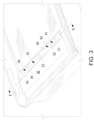
- FIG. 3 is a partial schematic isometric view of device 10 of FIG. 1 according to an embodiment.
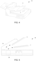
- FIG. 4 is a schematic view of device 10 of FIG. 1 according to an embodiment.
- FIG. 5 is a partial schematic view of device 10 of FIG. 1 according to an embodiment.
- the device 10 includes a scanner 20, a transparent member 30, a media ramp 40, and film element 51.
- device 10 further include a calibration label 60 and an adhesive layer 70.
- a medium traveling through device 10 travels along a media path 15 from an input tray 5 towards an output tray 7.
- media path 15 may be a generally "C" shaped media path.
- device 10 may be any imaging device to transport media along a "C" shaped media path.
- An “imaging device” may be a hardware device, such as a scanner, copier, multifunction printer (MFP), or any other device with functionalities to produce electronic data representing physical objects.
- MFP multifunction printer
- an MFP may be capable of performing a combination of multiple different functionalities such as, for example, printing, photocopying, scanning, faxing, etc.
- media may be any type of paper, photopolymers, thermopolymers, plastics, fabric, composite, metal, wood, etc., which may be stacked on a input tray 5 of device 10.
- device 10 may provide media to travel along media path 15 to be imaged by scanner 20.
- media path 15 may be a media path to transport media from input tray 5 to output tray 7.
- a medium traveling along media path 15 would traverse a scan zone 20a and travel up media ramp 40 to exit device 10.
- the media transitions in the path are may not be constant.
- the scanned image may have artifacts.
- the transition from a scan zone 20a to media ramp 40 may be improved to reduce scan artifacts.
- scanner 20 may be a hardware component to scan a physical object to produce electronic representations of the object.
- scanner 20 may scan or image a variety of physical objects placed in a scan zone of the scanner.
- scanner 20 may traverse the scan zone to image an object.
- scanner 20 may remain stationary and an object may travel along a scan zone of scanner 20 for imaging.
- scanner 20 is disposed in scan zone 20a.
- scan zone 20a may be the scan zone of a stationary scanner 20 to image a medium (e.g., a document) traversing across the scan zone along a "C" shaped media path 15.
- a transparent member 30 is disposed to cover scan zone 20a.
- transparent member 30 may be composed of any ridged transparent material with structural integrity to support an object being imaged.
- transparent member 30 may be a glass, a plexi-glass, a transparent plastic, etc.
- device 10 includes a calibration label 60 disposed below the transparent member 30 and above scanner 20.
- calibration label 60 extends over a portion of media ramp 40.
- calibration label 60 may be coupled to transparent member 30 and extend beyond a first edge 30a of transparent member 30 to be disposed on at least a portion of media ramp 40.
- the term “couple” or “couples” is intended to include suitable indirect and/or direct connections.
- calibration label 60 may include a notch or recess in which film 51 may be disposed at one end.
- calibration label 60 may be used to ensure consistent and high quality digital images of a medium. For example, different scanners, or the same scanner at different points in time, may scan media differently. In other words, a scanner response may differ between scan jobs.
- the calibration label 60 may be used to account for these variations to ensure a high quality digital image is produced.
- calibration label 60 may be a uniformly colored white strip that has a certain reflectance and is viewable by the scanner 20.
- the scanner 20 captures an image of calibration label 60 and may use the image of calibration label 60 to compensate for variations in scanner 20 response.
- variations in scanner response may occur at a point in time distinct from scanning. For example, calibration may occur periodically between scan jobs, on power up, or before each scan job.
- film 51 is disposed underneath transparent member 30.
- film 51 may be disposed inside calibration label 60 at a first end 51a.
- film 51 may be disposed adjacent to scan zone 20a at first end 51a and disposed to extend over at least a portion of media ramp 40 along the direction of media path 15 at a second end 51b.
- film 51 may be disposed over at least a portion of media ramp 40 to receive a leading edge of medium 100 traveling along media path 15.
- film 51 may be a polyester film.
- film 51 is a a biaxially-oriented polyethylene terephthalate.
- film 51 may be dimensioned to cover a portion of media ramp 40 leaving an uncovered portion.
- a majority of media ramp 40 may be uncovered.
- an adhesive layer 70 may be disposed between the calibration label 60 and the film 51 over media ramp 40. In some examples, adhesive layer 70 may extend beyond calibration label 60 on to media ramp 40 to couple film 51 to media ramp 40.
- film 52 may be a film substantially similar to film 51. In one embodiment, film 52 is spaced apart from the film 51 to form a channel 41 there between. In one embodiment, film 52 is disposed adjacent to scan zone 20a at a first end (not shown) and disposed to extend over at least a portion of media ramp 40 along the direction of media path 15 at a second end 52b. In one embodiment, film 52 is disposed underneath transparent member 30 at the first end. In another embodiment, film 52 is disposed adjacent to transparent member 30 at the first end. In examples, film 52 may be dimensioned to cover a portion of media ramp 40 leaving an uncovered portion. In examples, a majority of media ramp 40 may be uncovered. In some examples, adhesive layer 70 may be disposed to couple film 52 to calibration label 60 and media ramp 40 in a substantially similar manner as described above with respect to film 51.
- film 53 may be a film substantially similar to film 52.
- film 53 may be a film substantially similar to film 52.
- film 54 may be a film substantially similar to film 53.
- film 54 may be a film substantially similar to film 53.
- film 55 may be a film substantially similar to film 54. In examples, film 55 may be spaced apart from the film 51, film 52, film 53, and film 54. In such an examples, film 55 may be disposed to form channel 44 between film 55 and film 54. In examples, film 55 may be disposed adjacent to scan zone 20a at a first end (not shown) and disposed to extend over at least a portion of media ramp 40 along the direction of media path 15 at a second end (not shown). In an example, film 55 may be disposed underneath transparent member 30 at the first end. In other examples, film 55 may be disposed adjacent to transparent member 30 at the first end. In examples, film 55 may be dimensioned to cover a portion of media ramp 40 in a direction substantially perpendicular to media path 15.
- a majority of media ramp 40 perpendicular to media path 15 may be uncovered. In examples, a majority of media ramp 40 may be uncovered.
- adhesive layer 70 may be disposed to couple film 55 to calibration label 60 and media ramp 40 in a substantially similar manner as described above with respect to film 51.
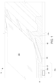
- FIG. 6 is a cross-sectional view of the device of FIG. 3 taken along line 6-6' according to an example.
- medium 100 is traveling along media path 15.
- device 10 may include one or more of film 51, film 52, film 53, film 54, and film 55.
- one film disposed over media ramp 40 it will be understood that the majority of the surface area of media ramp 40 adjacent to scan zone 20a will be bare of a film.
- the majority of the surface area of media ramp 40 adjacent to scan zone 20a will be bare of a film as depicted in FIG. 6 .
- FIG. 6 is a cross-sectional view of the device of FIG. 3 taken along line 6-6' according to an example.
- medium 100 is traveling along media path 15.
- device 10 may include one or more of film 51, film 52, film 53, film 54, and film 55.
- the majority of the surface area of media ramp 40 adjacent to scan zone 20a will be bare of a film.
- the majority of the surface area of media ramp 40 adjacent to scan zone 20a will
- a number of fluctuation points A are shown at which medium 100 contacts media ramp 40 after vibrations occur in medium 100 as it contacts film 51, film 52, film 53, film 54, and film 55. It will be understood that the number of fluctuation points A is reduced when a film is disposed over media ramp 40. In addition, it will be understood that the relative locations of film 51, film 52, film 53, film 54, and film 55 may impact the location and force applied to medium 100 to produce fluctuation points A.
Landscapes
- Engineering & Computer Science (AREA)
- Multimedia (AREA)
- Signal Processing (AREA)
- Facsimile Scanning Arrangements (AREA)
- Facsimiles In General (AREA)
Description
- Imaging devices - including scanners, copiers, facsimile machines, multifunction printers, all-in-one devices, or other devices - convert physical objects (e.g., documents, photographs, etc.) into electronic data. In some examples, imaging devices can include an automatic document feeder (ADFs) to receive stacks of media to provide to a scanner subassembly for imaging. ADFs may utilize a transmission having a series of motors and rollers to transport the media between trays.
-
US 2006/0044633 describes an image reading apparatus which comprises a document feeder, a reading unit and a guide device. - The following detailed description references the drawings, wherein:
-
FIG. 1 is a partial schematic isometric view of a device according to an embodiment. -
FIG. 2 is a partial schematic isometric view of the device ofFIG. 1 according to an embodiment. -
FIG. 3 is a partial schematic isometric view of the device ofFIG. 1 according to an embodiment. -
FIG. 4 is a schematic isometric view of the device ofFIG. 1 according to an embodiment. -
FIG. 5 is a partial schematic view of the device ofFIG. 1 according to an embodiment. -
FIG. 6 is a cross-sectional view of the device ofFIG. 3 taken along line 6-6' according to an embodiment. - An automatic document feeder (ADF) may be coupled to an imaging device to provide objects for scanning. An ADF may include an input tray to receive a stack of media for imaging and may transport the media stack through a scan zone to an output tray. To reduce ADF size, a number of ADFs stack the input tray and the output tray on top of each other to form a substantially "C" shaped media path. In such ADFs, the scan zone may contain a stationary scanner (e.g., a line scanner) to image a medium as it travels through the media path. The speed at which media travels past the scan zone should be kept constant when scanning the media. This may be achieved by ensuring smooth transitions through the "C" shaped media path. However, given the nature of the "C" shaped path, the media transitions in the path are not constant. When these transitions are not constant, a scanned image may have artifacts.
- To address these issues, in the examples described herein, a device is described which includes film element disposed on a media ramp in the "C" shaped media path to reduce scan artifacts. The device includes a media ramp downstream of a scan zone along the media path to direct a medium to an exit. A film element may be disposed on the media ramp to form channels. The film element may be composed of a polyester material such as biaxially-oriented polyethylene terephthalate. In examples, the film elements may create transition zones on the media ramp to reduce the number of places at which a leading edge of a medium traveling along a media path encounters the media ramp. The transition zone may be disposed between film elements and may be zones in which a change in direction of a medium traveling over the media ramp may be smoothed out. In such examples, it has been found that scan artifacts have been reduced.
- Accordingly, the present specification describes, in one embodiment, a device that includes a scanner disposed in a scan zone to image a medium traveling across the scan zone; a transparent member disposed over the scan zone; a media ramp disposed adjacent to the scan zone to direct the medium to an exit; and a first film element disposed underneath the transparent member and adjacent to the scan zone at a first end and disposed to extend over at least a portion of the media ramp at a second end. The invention is defined by the independent claims. The dependent claims define advantageous embodiments.
- Aln one embodiment, the present specification describes an imaging device that includes a scanner disposed in a scan zone to image a medium; a transparent member disposed over the scan zone; a media ramp disposed adjacent to the scan zone to guide the medium to an exit path; a first film element disposed underneath the transparent member and adjacent to the scan zone at a first end and disposed to extend over at least a portion of the media ramp at a second end; and a second film element spaced apart from the first film element to form a channel there between, the second film disposed underneath the transparent member and adjacent to the scan zone at a first end and disposed to extend over at least a portion of the media ramp at a second end.
- In yet another embodiment, the present specification describes an imaging device that includes a scanner disposed in a scan zone to image a medium; a transparent member disposed over the scan zone; a media ramp disposed adjacent to the scan zone to direct the medium to an exit path of an automatic document feeder; a first film element disposed underneath the transparent member and adjacent to the scan zone at a first end and disposed to extend over at least a portion of the media ramp at a second end; a second film element spaced apart from the first film element to form a channel there between, the second film disposed underneath the transparent member and adjacent to the scan zone at a first end and disposed to extend over at least a portion of the media ramp at a second end; and a calibration label disposed over the scan zone and underneath the transparent member and disposed to extend over at least a portion of the media ramp, the first end of the first film element and the first end of the second film element are disposed inside the calibration label.
- Referring now to the drawings,
FIG. 1 is a partial schematic isometric view of adevice 10 according to an embodiment.FIG. 2 is a partial schematic isometric view ofdevice 10 ofFIG. 1 according to an embodiment.FIG. 3 is a partial schematic isometric view ofdevice 10 ofFIG. 1 according to an embodiment.FIG. 4 is a schematic view ofdevice 10 ofFIG. 1 according to an embodiment.FIG. 5 is a partial schematic view ofdevice 10 ofFIG. 1 according to an embodiment. Thedevice 10 includes ascanner 20, atransparent member 30, amedia ramp 40, andfilm element 51. In examples,device 10 further include acalibration label 60 and anadhesive layer 70. In an embodiment, a medium traveling throughdevice 10 travels along amedia path 15 from aninput tray 5 towards anoutput tray 7. In examples,media path 15 may be a generally "C" shaped media path. - In examples,
device 10 may be any imaging device to transport media along a "C" shaped media path. An "imaging device" may be a hardware device, such as a scanner, copier, multifunction printer (MFP), or any other device with functionalities to produce electronic data representing physical objects. In some examples, an MFP may be capable of performing a combination of multiple different functionalities such as, for example, printing, photocopying, scanning, faxing, etc. In examples, media may be any type of paper, photopolymers, thermopolymers, plastics, fabric, composite, metal, wood, etc., which may be stacked on ainput tray 5 ofdevice 10. - In examples,
device 10 may provide media to travel alongmedia path 15 to be imaged byscanner 20. In examples,media path 15 may be a media path to transport media frominput tray 5 to outputtray 7. In examples, a medium traveling alongmedia path 15 would traverse ascan zone 20a and travel upmedia ramp 40 toexit device 10. In examples, given the nature of the "C" shaped path, the media transitions in the path are may not be constant. In examples, when these transitions are not constant, the scanned image may have artifacts. In the examples described herein, the transition from ascan zone 20a tomedia ramp 40 may be improved to reduce scan artifacts. - In examples,
scanner 20 may be a hardware component to scan a physical object to produce electronic representations of the object. In examples,scanner 20 may scan or image a variety of physical objects placed in a scan zone of the scanner. In examples,scanner 20 may traverse the scan zone to image an object. In other examples,scanner 20 may remain stationary and an object may travel along a scan zone ofscanner 20 for imaging. In the embodiment ofFIG. 1 ,scanner 20 is disposed inscan zone 20a. InFIGs. 1-6 ,scan zone 20a may be the scan zone of astationary scanner 20 to image a medium (e.g., a document) traversing across the scan zone along a "C"shaped media path 15. - In embodiments, a
transparent member 30 is disposed to coverscan zone 20a. In examples,transparent member 30 may be composed of any ridged transparent material with structural integrity to support an object being imaged. In examples,transparent member 30 may be a glass, a plexi-glass, a transparent plastic, etc. - In one embodiment,
device 10 includes acalibration label 60 disposed below thetransparent member 30 and abovescanner 20. In one embodiment,calibration label 60 extends over a portion ofmedia ramp 40. In examples,calibration label 60 may be coupled totransparent member 30 and extend beyond afirst edge 30a oftransparent member 30 to be disposed on at least a portion ofmedia ramp 40. In the following discussion and in the claims, the term "couple" or "couples" is intended to include suitable indirect and/or direct connections. Thus, if a first component is described as being coupled to a second component, that coupling may, for example, be: (1) through a direct electrical or mechanical connection, (2) through an indirect electrical or mechanical connection via other devices and connections, (3) through an optical electrical connection, (4) through a wireless electrical connection, and/or (5) another suitable coupling. The term "connect" or "connected" is intended to include suitable direct connections. InFIGs. 1-6 ,calibration label 60 may include a notch or recess in whichfilm 51 may be disposed at one end. In examples,calibration label 60 may be used to ensure consistent and high quality digital images of a medium. For example, different scanners, or the same scanner at different points in time, may scan media differently. In other words, a scanner response may differ between scan jobs. Thecalibration label 60 may be used to account for these variations to ensure a high quality digital image is produced. In examples,calibration label 60 may be a uniformly colored white strip that has a certain reflectance and is viewable by thescanner 20. In examples, during calibration, thescanner 20 captures an image ofcalibration label 60 and may use the image ofcalibration label 60 to compensate for variations inscanner 20 response. In examples, variations in scanner response may occur at a point in time distinct from scanning. For example, calibration may occur periodically between scan jobs, on power up, or before each scan job. - In an embodiment,
film 51 is disposed underneathtransparent member 30. In an example,film 51 may be disposed insidecalibration label 60 at afirst end 51a. In examples,film 51 may be disposed adjacent to scanzone 20a atfirst end 51a and disposed to extend over at least a portion ofmedia ramp 40 along the direction ofmedia path 15 at asecond end 51b. In examples,film 51 may be disposed over at least a portion ofmedia ramp 40 to receive a leading edge ofmedium 100 traveling alongmedia path 15. In examples,film 51 may be a polyester film. In an embodiment,film 51 is a a biaxially-oriented polyethylene terephthalate. In examples,film 51 may be dimensioned to cover a portion ofmedia ramp 40 leaving an uncovered portion. In examples, a majority ofmedia ramp 40 may be uncovered. In examples, anadhesive layer 70 may be disposed between thecalibration label 60 and thefilm 51 overmedia ramp 40. In some examples,adhesive layer 70 may extend beyondcalibration label 60 on tomedia ramp 40 to couplefilm 51 tomedia ramp 40. - In examples,
film 52 may be a film substantially similar tofilm 51. In one embodiment,film 52 is spaced apart from thefilm 51 to form achannel 41 there between. In one embodiment,film 52 is disposed adjacent to scanzone 20a at a first end (not shown) and disposed to extend over at least a portion ofmedia ramp 40 along the direction ofmedia path 15 at asecond end 52b. In one embodiment,film 52 is disposed underneathtransparent member 30 at the first end. In another embodiment,film 52 is disposed adjacent totransparent member 30 at the first end. In examples,film 52 may be dimensioned to cover a portion ofmedia ramp 40 leaving an uncovered portion. In examples, a majority ofmedia ramp 40 may be uncovered. In some examples,adhesive layer 70 may be disposed to couplefilm 52 tocalibration label 60 andmedia ramp 40 in a substantially similar manner as described above with respect tofilm 51. - In examples,
film 53 may be a film substantially similar tofilm 52. In an embodiment, film - 53 is spaced apart from the
film 51 andfilm 52. In another embodiment,film 53 is - disposed to form
channel 42 betweenfilm 53 andfilm 52. In this embodiment,film 53 is disposed - adjacent to scan
zone 20a at a first end (not shown) and disposed to extend over at least a portion ofmedia ramp 40 along the direction ofmedia path 15 at asecond end 53b. In one embodiment, film - 53 is disposed underneath
transparent member 30 at the first end. In another embodiment, film - 53 is
- disposed adjacent to
transparent member 30 at the first end. In examples,film 53 may be dimensioned to cover a portion ofmedia ramp 40 in a direction substantially perpendicular tomedia path 15. In examples, a majority ofmedia ramp 40 perpendicular tomedia path 15 may be uncovered. In examples, a majority ofmedia ramp 40 may be uncovered. In some examples,adhesive layer 70 may be disposed to couplefilm 53 tocalibration label 60 andmedia ramp 40 in a substantially similar manner as described above with respect tofilm 51. - In examples,
film 54 may be a film substantially similar tofilm 53. In an embodiment, film - 54 is spaced apart from the
film 51,film 52, andfilm 53.Film film 54 may - be disposed to form
channel 43 betweenfilm 54 andfilm 53. In the embodiment,film 54 is - disposed adjacent to scan
zone 20a at a first end (not shown) and disposed to extend over at least a portion ofmedia ramp 40 along the direction ofmedia path 15 at a second end 54b.Film 54 is - film disposed underneath
transparent member 30 at the first end. In other examples,film 54 may be disposed adjacent totransparent member 30 at the first end. In examples,film 54 may be dimensioned to cover a portion ofmedia ramp 40 in a direction - perpendicular to
media path 15 may be uncovered. In examples, a majority ofmedia ramp 40 may be uncovered. In some examples,adhesive layer 70 may be disposed to couplefilm 54 tocalibration label 60 andmedia ramp 40 in a substantially similar manner as described above with respect tofilm 51. - In examples,
film 55 may be a film substantially similar tofilm 54. In examples,film 55 may be spaced apart from thefilm 51,film 52,film 53, andfilm 54. In such an examples,film 55 may be disposed to formchannel 44 betweenfilm 55 andfilm 54. In examples,film 55 may be disposed adjacent to scanzone 20a at a first end (not shown) and disposed to extend over at least a portion ofmedia ramp 40 along the direction ofmedia path 15 at a second end (not shown). In an example,film 55 may be disposed underneathtransparent member 30 at the first end. In other examples,film 55 may be disposed adjacent totransparent member 30 at the first end. In examples,film 55 may be dimensioned to cover a portion ofmedia ramp 40 in a direction substantially perpendicular tomedia path 15. In examples, a majority ofmedia ramp 40 perpendicular tomedia path 15 may be uncovered. In examples, a majority ofmedia ramp 40 may be uncovered. In some examples,adhesive layer 70 may be disposed to couplefilm 55 tocalibration label 60 andmedia ramp 40 in a substantially similar manner as described above with respect tofilm 51. -
FIG. 6 is a cross-sectional view of the device ofFIG. 3 taken along line 6-6' according to an example. In the example ofFIG. 6 ,medium 100 is traveling alongmedia path 15. In examples,device 10 may include one or more offilm 51,film 52,film 53,film 54, andfilm 55. In an example with one film disposed overmedia ramp 40, it will be understood that the majority of the surface area ofmedia ramp 40 adjacent to scanzone 20a will be bare of a film. Similarly, in other examples in which more than one film is disposed overramp 40, the majority of the surface area ofmedia ramp 40 adjacent to scanzone 20a will be bare of a film as depicted inFIG. 6 . In the example ofFIG. 6 , a number of fluctuation points A are shown at which medium 100contacts media ramp 40 after vibrations occur inmedium 100 as itcontacts film 51,film 52,film 53,film 54, andfilm 55. It will be understood that the number of fluctuation points A is reduced when a film is disposed overmedia ramp 40. In addition, it will be understood that the relative locations offilm 51,film 52,film 53,film 54, andfilm 55 may impact the location and force applied to medium 100 to produce fluctuation points A. - While certain implementations have been shown and described above, various changes in form and details may be made. For example, some features that have been described in relation to one implementation and/or process can be related to other implementations. In other words, processes, features, components, and/or properties described in relation to one implementation can be useful in other implementations. Furthermore, it should be understood that the systems, apparatuses, and methods described herein can include various combinations and/or sub-combinations of the components and/or features of the different implementations described. Thus, features described with reference to one or more implementations can be combined with other implementations described herein.
- The above discussion is meant to be illustrative of the principles and various embodiments of the present disclosure. Numerous variations and modifications will become apparent to those skilled in the art once the above disclosure is fully appreciated. The present invention is defined by the subject matter of the appended claims. Additional aspects are provided in the dependent claims.
Claims (14)
- A device, comprising:a scanner (20) disposed in a scan zone (20a) to image a medium traveling across the scan zone (20a);a transparent member (30) disposed over the scan zone (20a);characterized in that:a media ramp (40) is disposed adjacent to the scan zone (20a) to direct the medium to an exit; anda first film element (51) is disposed underneath the transparent member (30) and adjacent to the scan zone (20a) at a first end and disposed to extend over at least a portion of the media ramp (40) at a second end.
- The device of claim 1, further comprising:
a second film element (52) spaced apart from the first film element (51) to form a channel (41) there between, wherein the second film element (52) is disposed adjacent to the scan zone (20a) at a first end and disposed to extend over at least a portion of the media ramp (40) at a second end. - The device of claim 1, further comprising:a calibration label (60) disposed over the scan zone and underneath the transparent member (30) and disposed to extend over at least a portion of the media ramp (40),wherein the first end of the first film element (51) is disposed inside the calibration label (60).
- The device of claim 1, wherein the media ramp (40) is downstream of the scan zone (20a) along a media path (15).
- The device of claim 2, further comprising:
a third film element (53) spaced apart from the first element (51) and the second film element (52), the third film (53) disposed adjacent to the scan zone (20a) at a first end and disposed to extend over at least a portion of the media ramp (40) at a second end. - The device of claim 1, wherein the first film element (51) is composed of a biaxially-oriented polyethylene terephthalate.
- An imaging device comprising the device of claim 1, and further comprising
a second film element (52) spaced apart from the first film element (51) to form a channel (41) there between, the second film (52) disposed underneath the transparent member (30) and adjacent to the scan zone (20a) at a first end and disposed to extend over at least a portion of the media ramp (40) at a second end. - The imaging device of claim 7, further comprising:a calibration label (60) disposed over the scan zone (20a) and underneath the transparent member (30) and disposed to extend over at least a portion of the media ramp (40),wherein the first end of the first film element (51) and the first end of the second film element (52) are disposed inside the calibration label (60).
- The imaging device of claim 8, further comprising:
a third film element (53) disposed inside the channel and spaced apart from the first element (51) and the second film element (52), the third film (53) disposed adjacent to the scan zone (20a) at a first end and disposed to extend over at least a portion of the media ramp (40) at a second end. - The imaging device of claim 7, further comprising:
a fourth film element (54) disposed outside the channel and spaced apart from the first element (51) and the second film element (52), the fourth film element (54) disposed adjacent to the scan zone (20a) at a first end and disposed to extend over at least a portion of the media ramp (40) at a second end. - The imaging device of claim 7 or claim 8 , wherein the first film element (51) and the second film element (52) are composed of a biaxially-oriented polyethylene terephthalate.
- The imaging device of claim 8, further comprising:
a third film element (53) spaced apart from the first element (51) and the second film element (52), the third film (53) disposed underneath the transparent member (30) and adjacent to the scan zone (20a) at a first end and disposed to extend over at least a portion of the media ramp (40) at a second end. - The imaging device of claim 12, wherein the third film element (53) is disposed in the channel to further define a first channel (41) and a second channel (42).
- The imaging device of claim 13, further comprising:
a fourth film element (54) disposed outside the channel and spaced apart from the first element (51) and the second film element (52), the fourth film element (54) disposed underneath the transparent member (30) and adjacent to the scan zone (20a) at a first end and disposed to extend over at least a portion of the media ramp (40) at a second end.
Applications Claiming Priority (1)
| Application Number | Priority Date | Filing Date | Title |
|---|---|---|---|
| PCT/US2016/051397 WO2018048457A1 (en) | 2016-09-12 | 2016-09-12 | Media ramp with film |
Publications (3)
| Publication Number | Publication Date |
|---|---|
| EP3510759A1 EP3510759A1 (en) | 2019-07-17 |
| EP3510759A4 EP3510759A4 (en) | 2020-05-13 |
| EP3510759B1 true EP3510759B1 (en) | 2022-03-09 |
Family
ID=61561596
Family Applications (1)
| Application Number | Title | Priority Date | Filing Date |
|---|---|---|---|
| EP16915909.2A Not-in-force EP3510759B1 (en) | 2016-09-12 | 2016-09-12 | Media ramp with film |
Country Status (4)
| Country | Link |
|---|---|
| US (1) | US10694065B2 (en) |
| EP (1) | EP3510759B1 (en) |
| CN (1) | CN109792470B (en) |
| WO (1) | WO2018048457A1 (en) |
Family Cites Families (22)
| Publication number | Priority date | Publication date | Assignee | Title |
|---|---|---|---|---|
| GB2178411B (en) | 1985-07-02 | 1990-03-14 | Konishiroku Photo Ind | Document feeding apparatus |
| JP4690520B2 (en) | 2000-04-20 | 2011-06-01 | 東芝テック株式会社 | Document feeder |
| US7295350B2 (en) * | 2001-09-10 | 2007-11-13 | Transpacific Ip Ltd | Photographic film scanning device |
| US7031028B2 (en) * | 2001-10-15 | 2006-04-18 | Rong-Ji Liu | Optical scanner equipped with plug-in calibration film |
| JP2003289422A (en) | 2002-01-24 | 2003-10-10 | Ricoh Co Ltd | Image reading device |
| JP3943942B2 (en) | 2002-01-31 | 2007-07-11 | キヤノン株式会社 | Document conveying apparatus, image reading apparatus, and image forming apparatus |
| JP3977140B2 (en) | 2002-05-17 | 2007-09-19 | キヤノン株式会社 | Document conveying device, document reading device including the same, and image forming apparatus |
| JP3626943B2 (en) | 2002-06-24 | 2005-03-09 | ニスカ株式会社 | Automatic document feeder |
| JP2004145021A (en) | 2002-10-24 | 2004-05-20 | Ricoh Co Ltd | Image forming device |
| US7251063B2 (en) * | 2002-12-05 | 2007-07-31 | Hewlett-Packard Development Company, L.P. | Automatic document feeder |
| US6830401B1 (en) * | 2003-09-10 | 2004-12-14 | Hewlett-Packard Development Company, L.P. | Mechanical architecture for printer trays |
| RU41220U1 (en) | 2004-05-28 | 2004-10-10 | Константинов Станислав Вячеславович | SCANNER |
| JP4375556B2 (en) * | 2004-08-31 | 2009-12-02 | ブラザー工業株式会社 | Document feeder |
| US8098411B2 (en) * | 2004-08-31 | 2012-01-17 | Brother Kogyo Kabushiki Kaisha | Image reading apparatus |
| KR100577689B1 (en) | 2005-01-19 | 2006-05-10 | 삼성전자주식회사 | An image reading apparatus, a method for checking contamination of a guide film of the image reading apparatus, and an image forming apparatus using the image reading apparatus. |
| DE102006043956A1 (en) * | 2006-09-14 | 2008-04-03 | Deutsche Thomson Ohg | Film scanner and detection device for it |
| TW200845721A (en) | 2007-05-10 | 2008-11-16 | Avision Inc | Scanning module and scanner using the same |
| CN101547276B (en) | 2008-03-25 | 2011-06-29 | 旭丽电子(广州)有限公司 | Automatic document feeding device |
| US8177445B2 (en) * | 2008-04-01 | 2012-05-15 | Hewlett-Packard Development Company, L.P. | Over-center mechanism |
| US8155575B2 (en) * | 2008-05-16 | 2012-04-10 | Hewlett-Packard Development Company, L.P. | Systems and methods for orienting media for improved scan quality |
| TWI395461B (en) | 2008-11-11 | 2013-05-01 | Avision Inc | Automatic feeding scan apparatus having non-linear paper path |
| JP5560681B2 (en) * | 2008-12-08 | 2014-07-30 | セイコーエプソン株式会社 | Recording method, recorded matter, recording apparatus, and operation control program |
-
2016
- 2016-09-12 WO PCT/US2016/051397 patent/WO2018048457A1/en not_active Ceased
- 2016-09-12 EP EP16915909.2A patent/EP3510759B1/en not_active Not-in-force
- 2016-09-12 CN CN201680089179.XA patent/CN109792470B/en not_active Expired - Fee Related
- 2016-09-12 US US16/331,277 patent/US10694065B2/en not_active Expired - Fee Related
Also Published As
| Publication number | Publication date |
|---|---|
| US10694065B2 (en) | 2020-06-23 |
| US20190356810A1 (en) | 2019-11-21 |
| CN109792470B (en) | 2021-07-06 |
| WO2018048457A1 (en) | 2018-03-15 |
| EP3510759A1 (en) | 2019-07-17 |
| CN109792470A (en) | 2019-05-21 |
| EP3510759A4 (en) | 2020-05-13 |
Similar Documents
| Publication | Publication Date | Title |
|---|---|---|
| US8400690B2 (en) | Apparatus and method for detecting and compensating for multi-fed document scanning errors | |
| JP2016088645A (en) | Sheet transport device | |
| JP2003173109A (en) | Image forming apparatus and image forming adjustment method | |
| US10136001B2 (en) | Image forming apparatus, method for controlling image forming apparatus, and storage medium | |
| CN104253918B (en) | Image reading device, image forming apparatus, and optical unit | |
| JP2026069711A (en) | Image reading device | |
| JP2017204684A (en) | Reading apparatus and image forming apparatus | |
| CN103795884B (en) | Image processing system and image forming method | |
| EP3091726A1 (en) | Duplex automatic document handler (dadh) with one-piece platen | |
| US8134755B2 (en) | Image reading apparatus | |
| US9906665B1 (en) | Document handler having opposing belts maintaining constant sheet contact for scanning small and delicate sheets | |
| JP4840079B2 (en) | Reader and copier | |
| US10694065B2 (en) | Media ramp with film | |
| JP5306131B2 (en) | Image reading device | |
| US20120008156A1 (en) | Image-processing apparatus with oblique plane for supporting originals | |
| US8351096B2 (en) | Image scanning unit | |
| JP2005343582A (en) | Paper feeding device and image forming apparatus | |
| JP2020117328A (en) | Sheet transport device | |
| US20080291511A1 (en) | Automatic document feeder for use with office document | |
| JP6623710B2 (en) | Image reading apparatus and image forming apparatus | |
| US8054507B2 (en) | Image data luminance compensating method and sheet-feeding scanning apparatus using such method | |
| JP3706802B2 (en) | Image forming apparatus | |
| KR100465329B1 (en) | Automatic document feeding apparatus | |
| JP2017085523A (en) | Image reader | |
| US9400473B1 (en) | Variable capacity paper tray |
Legal Events
| Date | Code | Title | Description |
|---|---|---|---|
| STAA | Information on the status of an ep patent application or granted ep patent |
Free format text: STATUS: THE INTERNATIONAL PUBLICATION HAS BEEN MADE |
|
| PUAI | Public reference made under article 153(3) epc to a published international application that has entered the european phase |
Free format text: ORIGINAL CODE: 0009012 |
|
| STAA | Information on the status of an ep patent application or granted ep patent |
Free format text: STATUS: REQUEST FOR EXAMINATION WAS MADE |
|
| 17P | Request for examination filed |
Effective date: 20190311 |
|
| AK | Designated contracting states |
Kind code of ref document: A1 Designated state(s): AL AT BE BG CH CY CZ DE DK EE ES FI FR GB GR HR HU IE IS IT LI LT LU LV MC MK MT NL NO PL PT RO RS SE SI SK SM TR |
|
| AX | Request for extension of the european patent |
Extension state: BA ME |
|
| DAV | Request for validation of the european patent (deleted) | ||
| DAX | Request for extension of the european patent (deleted) | ||
| A4 | Supplementary search report drawn up and despatched |
Effective date: 20200417 |
|
| RIC1 | Information provided on ipc code assigned before grant |
Ipc: H04N 1/12 20060101ALI20200408BHEP Ipc: H04N 1/00 20060101AFI20200408BHEP Ipc: H04N 1/10 20060101ALI20200408BHEP |
|
| REG | Reference to a national code |
Ref country code: DE Ref legal event code: R079 Ref document number: 602016069976 Country of ref document: DE Free format text: PREVIOUS MAIN CLASS: H04N0001100000 Ipc: H04N0001193000 |
|
| RIC1 | Information provided on ipc code assigned before grant |
Ipc: H04N 1/10 20060101ALI20210406BHEP Ipc: H04N 1/12 20060101ALI20210406BHEP Ipc: H04N 1/00 20060101ALI20210406BHEP Ipc: H04N 1/193 20060101AFI20210406BHEP |
|
| GRAP | Despatch of communication of intention to grant a patent |
Free format text: ORIGINAL CODE: EPIDOSNIGR1 |
|
| STAA | Information on the status of an ep patent application or granted ep patent |
Free format text: STATUS: GRANT OF PATENT IS INTENDED |
|
| GRAJ | Information related to disapproval of communication of intention to grant by the applicant or resumption of examination proceedings by the epo deleted |
Free format text: ORIGINAL CODE: EPIDOSDIGR1 |
|
| GRAP | Despatch of communication of intention to grant a patent |
Free format text: ORIGINAL CODE: EPIDOSNIGR1 |
|
| INTG | Intention to grant announced |
Effective date: 20210615 |
|
| GRAJ | Information related to disapproval of communication of intention to grant by the applicant or resumption of examination proceedings by the epo deleted |
Free format text: ORIGINAL CODE: EPIDOSDIGR1 |
|
| GRAJ | Information related to disapproval of communication of intention to grant by the applicant or resumption of examination proceedings by the epo deleted |
Free format text: ORIGINAL CODE: EPIDOSDIGR1 |
|
| GRAP | Despatch of communication of intention to grant a patent |
Free format text: ORIGINAL CODE: EPIDOSNIGR1 |
|
| INTG | Intention to grant announced |
Effective date: 20210705 |
|
| GRAP | Despatch of communication of intention to grant a patent |
Free format text: ORIGINAL CODE: EPIDOSNIGR1 |
|
| INTG | Intention to grant announced |
Effective date: 20210705 |
|
| GRAJ | Information related to disapproval of communication of intention to grant by the applicant or resumption of examination proceedings by the epo deleted |
Free format text: ORIGINAL CODE: EPIDOSDIGR1 |
|
| GRAP | Despatch of communication of intention to grant a patent |
Free format text: ORIGINAL CODE: EPIDOSNIGR1 |
|
| INTG | Intention to grant announced |
Effective date: 20210804 |
|
| INTG | Intention to grant announced |
Effective date: 20210812 |
|
| INTG | Intention to grant announced |
Effective date: 20210830 |
|
| GRAJ | Information related to disapproval of communication of intention to grant by the applicant or resumption of examination proceedings by the epo deleted |
Free format text: ORIGINAL CODE: EPIDOSDIGR1 |
|
| STAA | Information on the status of an ep patent application or granted ep patent |
Free format text: STATUS: REQUEST FOR EXAMINATION WAS MADE |
|
| GRAP | Despatch of communication of intention to grant a patent |
Free format text: ORIGINAL CODE: EPIDOSNIGR1 |
|
| STAA | Information on the status of an ep patent application or granted ep patent |
Free format text: STATUS: GRANT OF PATENT IS INTENDED |
|
| INTC | Intention to grant announced (deleted) | ||
| INTG | Intention to grant announced |
Effective date: 20211222 |
|
| GRAS | Grant fee paid |
Free format text: ORIGINAL CODE: EPIDOSNIGR3 |
|
| GRAA | (expected) grant |
Free format text: ORIGINAL CODE: 0009210 |
|
| STAA | Information on the status of an ep patent application or granted ep patent |
Free format text: STATUS: THE PATENT HAS BEEN GRANTED |
|
| AK | Designated contracting states |
Kind code of ref document: B1 Designated state(s): AL AT BE BG CH CY CZ DE DK EE ES FI FR GB GR HR HU IE IS IT LI LT LU LV MC MK MT NL NO PL PT RO RS SE SI SK SM TR |
|
| REG | Reference to a national code |
Ref country code: CH Ref legal event code: EP Ref country code: AT Ref legal event code: REF Ref document number: 1475102 Country of ref document: AT Kind code of ref document: T Effective date: 20220315 |
|
| REG | Reference to a national code |
Ref country code: IE Ref legal event code: FG4D |
|
| REG | Reference to a national code |
Ref country code: DE Ref legal event code: R096 Ref document number: 602016069976 Country of ref document: DE |
|
| REG | Reference to a national code |
Ref country code: LT Ref legal event code: MG9D |
|
| REG | Reference to a national code |
Ref country code: NL Ref legal event code: MP Effective date: 20220309 |
|
| PG25 | Lapsed in a contracting state [announced via postgrant information from national office to epo] |
Ref country code: SE Free format text: LAPSE BECAUSE OF FAILURE TO SUBMIT A TRANSLATION OF THE DESCRIPTION OR TO PAY THE FEE WITHIN THE PRESCRIBED TIME-LIMIT Effective date: 20220309 Ref country code: RS Free format text: LAPSE BECAUSE OF FAILURE TO SUBMIT A TRANSLATION OF THE DESCRIPTION OR TO PAY THE FEE WITHIN THE PRESCRIBED TIME-LIMIT Effective date: 20220309 Ref country code: NO Free format text: LAPSE BECAUSE OF FAILURE TO SUBMIT A TRANSLATION OF THE DESCRIPTION OR TO PAY THE FEE WITHIN THE PRESCRIBED TIME-LIMIT Effective date: 20220609 Ref country code: LT Free format text: LAPSE BECAUSE OF FAILURE TO SUBMIT A TRANSLATION OF THE DESCRIPTION OR TO PAY THE FEE WITHIN THE PRESCRIBED TIME-LIMIT Effective date: 20220309 Ref country code: HR Free format text: LAPSE BECAUSE OF FAILURE TO SUBMIT A TRANSLATION OF THE DESCRIPTION OR TO PAY THE FEE WITHIN THE PRESCRIBED TIME-LIMIT Effective date: 20220309 Ref country code: BG Free format text: LAPSE BECAUSE OF FAILURE TO SUBMIT A TRANSLATION OF THE DESCRIPTION OR TO PAY THE FEE WITHIN THE PRESCRIBED TIME-LIMIT Effective date: 20220609 |
|
| REG | Reference to a national code |
Ref country code: AT Ref legal event code: MK05 Ref document number: 1475102 Country of ref document: AT Kind code of ref document: T Effective date: 20220309 |
|
| PG25 | Lapsed in a contracting state [announced via postgrant information from national office to epo] |
Ref country code: LV Free format text: LAPSE BECAUSE OF FAILURE TO SUBMIT A TRANSLATION OF THE DESCRIPTION OR TO PAY THE FEE WITHIN THE PRESCRIBED TIME-LIMIT Effective date: 20220309 Ref country code: GR Free format text: LAPSE BECAUSE OF FAILURE TO SUBMIT A TRANSLATION OF THE DESCRIPTION OR TO PAY THE FEE WITHIN THE PRESCRIBED TIME-LIMIT Effective date: 20220610 Ref country code: FI Free format text: LAPSE BECAUSE OF FAILURE TO SUBMIT A TRANSLATION OF THE DESCRIPTION OR TO PAY THE FEE WITHIN THE PRESCRIBED TIME-LIMIT Effective date: 20220309 |
|
| PG25 | Lapsed in a contracting state [announced via postgrant information from national office to epo] |
Ref country code: NL Free format text: LAPSE BECAUSE OF FAILURE TO SUBMIT A TRANSLATION OF THE DESCRIPTION OR TO PAY THE FEE WITHIN THE PRESCRIBED TIME-LIMIT Effective date: 20220309 |
|
| PG25 | Lapsed in a contracting state [announced via postgrant information from national office to epo] |
Ref country code: SM Free format text: LAPSE BECAUSE OF FAILURE TO SUBMIT A TRANSLATION OF THE DESCRIPTION OR TO PAY THE FEE WITHIN THE PRESCRIBED TIME-LIMIT Effective date: 20220309 Ref country code: SK Free format text: LAPSE BECAUSE OF FAILURE TO SUBMIT A TRANSLATION OF THE DESCRIPTION OR TO PAY THE FEE WITHIN THE PRESCRIBED TIME-LIMIT Effective date: 20220309 Ref country code: RO Free format text: LAPSE BECAUSE OF FAILURE TO SUBMIT A TRANSLATION OF THE DESCRIPTION OR TO PAY THE FEE WITHIN THE PRESCRIBED TIME-LIMIT Effective date: 20220309 Ref country code: PT Free format text: LAPSE BECAUSE OF FAILURE TO SUBMIT A TRANSLATION OF THE DESCRIPTION OR TO PAY THE FEE WITHIN THE PRESCRIBED TIME-LIMIT Effective date: 20220711 Ref country code: ES Free format text: LAPSE BECAUSE OF FAILURE TO SUBMIT A TRANSLATION OF THE DESCRIPTION OR TO PAY THE FEE WITHIN THE PRESCRIBED TIME-LIMIT Effective date: 20220309 Ref country code: EE Free format text: LAPSE BECAUSE OF FAILURE TO SUBMIT A TRANSLATION OF THE DESCRIPTION OR TO PAY THE FEE WITHIN THE PRESCRIBED TIME-LIMIT Effective date: 20220309 Ref country code: CZ Free format text: LAPSE BECAUSE OF FAILURE TO SUBMIT A TRANSLATION OF THE DESCRIPTION OR TO PAY THE FEE WITHIN THE PRESCRIBED TIME-LIMIT Effective date: 20220309 Ref country code: AT Free format text: LAPSE BECAUSE OF FAILURE TO SUBMIT A TRANSLATION OF THE DESCRIPTION OR TO PAY THE FEE WITHIN THE PRESCRIBED TIME-LIMIT Effective date: 20220309 |
|
| PG25 | Lapsed in a contracting state [announced via postgrant information from national office to epo] |
Ref country code: PL Free format text: LAPSE BECAUSE OF FAILURE TO SUBMIT A TRANSLATION OF THE DESCRIPTION OR TO PAY THE FEE WITHIN THE PRESCRIBED TIME-LIMIT Effective date: 20220309 Ref country code: IS Free format text: LAPSE BECAUSE OF FAILURE TO SUBMIT A TRANSLATION OF THE DESCRIPTION OR TO PAY THE FEE WITHIN THE PRESCRIBED TIME-LIMIT Effective date: 20220709 Ref country code: AL Free format text: LAPSE BECAUSE OF FAILURE TO SUBMIT A TRANSLATION OF THE DESCRIPTION OR TO PAY THE FEE WITHIN THE PRESCRIBED TIME-LIMIT Effective date: 20220309 |
|
| REG | Reference to a national code |
Ref country code: DE Ref legal event code: R097 Ref document number: 602016069976 Country of ref document: DE |
|
| PLBE | No opposition filed within time limit |
Free format text: ORIGINAL CODE: 0009261 |
|
| STAA | Information on the status of an ep patent application or granted ep patent |
Free format text: STATUS: NO OPPOSITION FILED WITHIN TIME LIMIT |
|
| PG25 | Lapsed in a contracting state [announced via postgrant information from national office to epo] |
Ref country code: DK Free format text: LAPSE BECAUSE OF FAILURE TO SUBMIT A TRANSLATION OF THE DESCRIPTION OR TO PAY THE FEE WITHIN THE PRESCRIBED TIME-LIMIT Effective date: 20220309 |
|
| 26N | No opposition filed |
Effective date: 20221212 |
|
| PG25 | Lapsed in a contracting state [announced via postgrant information from national office to epo] |
Ref country code: SI Free format text: LAPSE BECAUSE OF FAILURE TO SUBMIT A TRANSLATION OF THE DESCRIPTION OR TO PAY THE FEE WITHIN THE PRESCRIBED TIME-LIMIT Effective date: 20220309 |
|
| PG25 | Lapsed in a contracting state [announced via postgrant information from national office to epo] |
Ref country code: MC Free format text: LAPSE BECAUSE OF FAILURE TO SUBMIT A TRANSLATION OF THE DESCRIPTION OR TO PAY THE FEE WITHIN THE PRESCRIBED TIME-LIMIT Effective date: 20220309 |
|
| REG | Reference to a national code |
Ref country code: CH Ref legal event code: PL |
|
| REG | Reference to a national code |
Ref country code: BE Ref legal event code: MM Effective date: 20220930 |
|
| PG25 | Lapsed in a contracting state [announced via postgrant information from national office to epo] |
Ref country code: LU Free format text: LAPSE BECAUSE OF NON-PAYMENT OF DUE FEES Effective date: 20220912 |
|
| PG25 | Lapsed in a contracting state [announced via postgrant information from national office to epo] |
Ref country code: LI Free format text: LAPSE BECAUSE OF NON-PAYMENT OF DUE FEES Effective date: 20220930 Ref country code: IT Free format text: LAPSE BECAUSE OF FAILURE TO SUBMIT A TRANSLATION OF THE DESCRIPTION OR TO PAY THE FEE WITHIN THE PRESCRIBED TIME-LIMIT Effective date: 20220309 Ref country code: IE Free format text: LAPSE BECAUSE OF NON-PAYMENT OF DUE FEES Effective date: 20220912 Ref country code: CH Free format text: LAPSE BECAUSE OF NON-PAYMENT OF DUE FEES Effective date: 20220930 |
|
| PG25 | Lapsed in a contracting state [announced via postgrant information from national office to epo] |
Ref country code: BE Free format text: LAPSE BECAUSE OF NON-PAYMENT OF DUE FEES Effective date: 20220930 |
|
| PGFP | Annual fee paid to national office [announced via postgrant information from national office to epo] |
Ref country code: GB Payment date: 20230823 Year of fee payment: 8 |
|
| PGFP | Annual fee paid to national office [announced via postgrant information from national office to epo] |
Ref country code: FR Payment date: 20230822 Year of fee payment: 8 Ref country code: DE Payment date: 20230822 Year of fee payment: 8 |
|
| PG25 | Lapsed in a contracting state [announced via postgrant information from national office to epo] |
Ref country code: HU Free format text: LAPSE BECAUSE OF FAILURE TO SUBMIT A TRANSLATION OF THE DESCRIPTION OR TO PAY THE FEE WITHIN THE PRESCRIBED TIME-LIMIT; INVALID AB INITIO Effective date: 20160912 |
|
| PG25 | Lapsed in a contracting state [announced via postgrant information from national office to epo] |
Ref country code: CY Free format text: LAPSE BECAUSE OF FAILURE TO SUBMIT A TRANSLATION OF THE DESCRIPTION OR TO PAY THE FEE WITHIN THE PRESCRIBED TIME-LIMIT Effective date: 20220309 |
|
| PG25 | Lapsed in a contracting state [announced via postgrant information from national office to epo] |
Ref country code: MK Free format text: LAPSE BECAUSE OF FAILURE TO SUBMIT A TRANSLATION OF THE DESCRIPTION OR TO PAY THE FEE WITHIN THE PRESCRIBED TIME-LIMIT Effective date: 20220309 |
|
| PG25 | Lapsed in a contracting state [announced via postgrant information from national office to epo] |
Ref country code: MT Free format text: LAPSE BECAUSE OF FAILURE TO SUBMIT A TRANSLATION OF THE DESCRIPTION OR TO PAY THE FEE WITHIN THE PRESCRIBED TIME-LIMIT Effective date: 20220309 |
|
| REG | Reference to a national code |
Ref country code: DE Ref legal event code: R119 Ref document number: 602016069976 Country of ref document: DE |
|
| GBPC | Gb: european patent ceased through non-payment of renewal fee |
Effective date: 20240912 |
|
| PG25 | Lapsed in a contracting state [announced via postgrant information from national office to epo] |
Ref country code: DE Free format text: LAPSE BECAUSE OF NON-PAYMENT OF DUE FEES Effective date: 20250401 |
|
| PG25 | Lapsed in a contracting state [announced via postgrant information from national office to epo] |
Ref country code: GB Free format text: LAPSE BECAUSE OF NON-PAYMENT OF DUE FEES Effective date: 20240912 |
|
| PG25 | Lapsed in a contracting state [announced via postgrant information from national office to epo] |
Ref country code: FR Free format text: LAPSE BECAUSE OF NON-PAYMENT OF DUE FEES Effective date: 20240930 |
|
| PG25 | Lapsed in a contracting state [announced via postgrant information from national office to epo] |
Ref country code: TR Free format text: LAPSE BECAUSE OF FAILURE TO SUBMIT A TRANSLATION OF THE DESCRIPTION OR TO PAY THE FEE WITHIN THE PRESCRIBED TIME-LIMIT Effective date: 20220309 |