EP3510222B1 - Door hinge - Google Patents
Door hinge Download PDFInfo
- Publication number
- EP3510222B1 EP3510222B1 EP17748864.0A EP17748864A EP3510222B1 EP 3510222 B1 EP3510222 B1 EP 3510222B1 EP 17748864 A EP17748864 A EP 17748864A EP 3510222 B1 EP3510222 B1 EP 3510222B1
- Authority
- EP
- European Patent Office
- Prior art keywords
- pin
- hinge
- panel
- socket
- hinge portion
- Prior art date
- Legal status (The legal status is an assumption and is not a legal conclusion. Google has not performed a legal analysis and makes no representation as to the accuracy of the status listed.)
- Active
Links
Images





Classifications
-
- E—FIXED CONSTRUCTIONS
- E05—LOCKS; KEYS; WINDOW OR DOOR FITTINGS; SAFES
- E05D—HINGES OR SUSPENSION DEVICES FOR DOORS, WINDOWS OR WINGS
- E05D7/00—Hinges or pivots of special construction
- E05D7/10—Hinges or pivots of special construction to allow easy separation or connection of the parts at the hinge axis
- E05D7/1061—Hinges or pivots of special construction to allow easy separation or connection of the parts at the hinge axis in a radial direction
- E05D7/1066—Hinges or pivots of special construction to allow easy separation or connection of the parts at the hinge axis in a radial direction requiring a specific angular position
-
- A—HUMAN NECESSITIES
- A47—FURNITURE; DOMESTIC ARTICLES OR APPLIANCES; COFFEE MILLS; SPICE MILLS; SUCTION CLEANERS IN GENERAL
- A47K—SANITARY EQUIPMENT; ACCESSORIES THEREFOR, e.g. TOILET ACCESSORIES
- A47K3/00—Baths; Showers; Appurtenances therefor
- A47K3/28—Showers or bathing douches
- A47K3/30—Screens or collapsible cabinets for showers or baths
- A47K3/36—Articulated screens
-
- E—FIXED CONSTRUCTIONS
- E05—LOCKS; KEYS; WINDOW OR DOOR FITTINGS; SAFES
- E05D—HINGES OR SUSPENSION DEVICES FOR DOORS, WINDOWS OR WINGS
- E05D7/00—Hinges or pivots of special construction
- E05D7/10—Hinges or pivots of special construction to allow easy separation or connection of the parts at the hinge axis
- E05D7/1061—Hinges or pivots of special construction to allow easy separation or connection of the parts at the hinge axis in a radial direction
- E05D7/1066—Hinges or pivots of special construction to allow easy separation or connection of the parts at the hinge axis in a radial direction requiring a specific angular position
- E05D7/1072—Hinges or pivots of special construction to allow easy separation or connection of the parts at the hinge axis in a radial direction requiring a specific angular position the pin having a non-circular cross-section
-
- E—FIXED CONSTRUCTIONS
- E05—LOCKS; KEYS; WINDOW OR DOOR FITTINGS; SAFES
- E05D—HINGES OR SUSPENSION DEVICES FOR DOORS, WINDOWS OR WINGS
- E05D5/00—Construction of single parts, e.g. the parts for attachment
- E05D5/02—Parts for attachment, e.g. flaps
- E05D5/0246—Parts for attachment, e.g. flaps for attachment to glass panels
-
- A—HUMAN NECESSITIES
- A47—FURNITURE; DOMESTIC ARTICLES OR APPLIANCES; COFFEE MILLS; SPICE MILLS; SUCTION CLEANERS IN GENERAL
- A47K—SANITARY EQUIPMENT; ACCESSORIES THEREFOR, e.g. TOILET ACCESSORIES
- A47K3/00—Baths; Showers; Appurtenances therefor
- A47K3/28—Showers or bathing douches
- A47K3/283—Fixed showers
- A47K3/284—Pre-fabricated shower cabinets
-
- A—HUMAN NECESSITIES
- A47—FURNITURE; DOMESTIC ARTICLES OR APPLIANCES; COFFEE MILLS; SPICE MILLS; SUCTION CLEANERS IN GENERAL
- A47K—SANITARY EQUIPMENT; ACCESSORIES THEREFOR, e.g. TOILET ACCESSORIES
- A47K3/00—Baths; Showers; Appurtenances therefor
- A47K3/28—Showers or bathing douches
- A47K3/30—Screens or collapsible cabinets for showers or baths
-
- E—FIXED CONSTRUCTIONS
- E05—LOCKS; KEYS; WINDOW OR DOOR FITTINGS; SAFES
- E05D—HINGES OR SUSPENSION DEVICES FOR DOORS, WINDOWS OR WINGS
- E05D11/00—Additional features or accessories of hinges
- E05D11/0054—Covers, e.g. for protection
-
- E—FIXED CONSTRUCTIONS
- E05—LOCKS; KEYS; WINDOW OR DOOR FITTINGS; SAFES
- E05D—HINGES OR SUSPENSION DEVICES FOR DOORS, WINDOWS OR WINGS
- E05D3/00—Hinges with pins
- E05D3/02—Hinges with pins with one pin
-
- E—FIXED CONSTRUCTIONS
- E05—LOCKS; KEYS; WINDOW OR DOOR FITTINGS; SAFES
- E05D—HINGES OR SUSPENSION DEVICES FOR DOORS, WINDOWS OR WINGS
- E05D5/00—Construction of single parts, e.g. the parts for attachment
- E05D5/02—Parts for attachment, e.g. flaps
-
- E—FIXED CONSTRUCTIONS
- E05—LOCKS; KEYS; WINDOW OR DOOR FITTINGS; SAFES
- E05D—HINGES OR SUSPENSION DEVICES FOR DOORS, WINDOWS OR WINGS
- E05D7/00—Hinges or pivots of special construction
- E05D7/10—Hinges or pivots of special construction to allow easy separation or connection of the parts at the hinge axis
- E05D7/1061—Hinges or pivots of special construction to allow easy separation or connection of the parts at the hinge axis in a radial direction
-
- A—HUMAN NECESSITIES
- A47—FURNITURE; DOMESTIC ARTICLES OR APPLIANCES; COFFEE MILLS; SPICE MILLS; SUCTION CLEANERS IN GENERAL
- A47K—SANITARY EQUIPMENT; ACCESSORIES THEREFOR, e.g. TOILET ACCESSORIES
- A47K3/00—Baths; Showers; Appurtenances therefor
- A47K3/28—Showers or bathing douches
- A47K3/30—Screens or collapsible cabinets for showers or baths
- A47K3/36—Articulated screens
- A47K2003/367—Hinges urging the articulated screen in one or more stable positions
-
- E—FIXED CONSTRUCTIONS
- E05—LOCKS; KEYS; WINDOW OR DOOR FITTINGS; SAFES
- E05F—DEVICES FOR MOVING WINGS INTO OPEN OR CLOSED POSITION; CHECKS FOR WINGS; WING FITTINGS NOT OTHERWISE PROVIDED FOR, CONCERNED WITH THE FUNCTIONING OF THE WING
- E05F3/00—Closers or openers with braking devices, e.g. checks; Construction of pneumatic or liquid braking devices
- E05F3/02—Closers or openers with braking devices, e.g. checks; Construction of pneumatic or liquid braking devices with pneumatic piston brakes
-
- E—FIXED CONSTRUCTIONS
- E05—LOCKS; KEYS; WINDOW OR DOOR FITTINGS; SAFES
- E05F—DEVICES FOR MOVING WINGS INTO OPEN OR CLOSED POSITION; CHECKS FOR WINGS; WING FITTINGS NOT OTHERWISE PROVIDED FOR, CONCERNED WITH THE FUNCTIONING OF THE WING
- E05F3/00—Closers or openers with braking devices, e.g. checks; Construction of pneumatic or liquid braking devices
- E05F3/04—Closers or openers with braking devices, e.g. checks; Construction of pneumatic or liquid braking devices with liquid piston brakes
-
- E—FIXED CONSTRUCTIONS
- E05—LOCKS; KEYS; WINDOW OR DOOR FITTINGS; SAFES
- E05Y—INDEXING SCHEME ASSOCIATED WITH SUBCLASSES E05D AND E05F, RELATING TO CONSTRUCTION ELEMENTS, ELECTRIC CONTROL, POWER SUPPLY, POWER SIGNAL OR TRANSMISSION, USER INTERFACES, MOUNTING OR COUPLING, DETAILS, ACCESSORIES, AUXILIARY OPERATIONS NOT OTHERWISE PROVIDED FOR, APPLICATION THEREOF
- E05Y2201/00—Constructional elements; Accessories therefor
- E05Y2201/10—Covers; Housings
- E05Y2201/11—Covers
-
- E—FIXED CONSTRUCTIONS
- E05—LOCKS; KEYS; WINDOW OR DOOR FITTINGS; SAFES
- E05Y—INDEXING SCHEME ASSOCIATED WITH SUBCLASSES E05D AND E05F, RELATING TO CONSTRUCTION ELEMENTS, ELECTRIC CONTROL, POWER SUPPLY, POWER SIGNAL OR TRANSMISSION, USER INTERFACES, MOUNTING OR COUPLING, DETAILS, ACCESSORIES, AUXILIARY OPERATIONS NOT OTHERWISE PROVIDED FOR, APPLICATION THEREOF
- E05Y2201/00—Constructional elements; Accessories therefor
- E05Y2201/20—Brakes; Disengaging means; Holders; Stops; Valves; Accessories therefor
- E05Y2201/21—Brakes
- E05Y2201/212—Buffers
-
- E—FIXED CONSTRUCTIONS
- E05—LOCKS; KEYS; WINDOW OR DOOR FITTINGS; SAFES
- E05Y—INDEXING SCHEME ASSOCIATED WITH SUBCLASSES E05D AND E05F, RELATING TO CONSTRUCTION ELEMENTS, ELECTRIC CONTROL, POWER SUPPLY, POWER SIGNAL OR TRANSMISSION, USER INTERFACES, MOUNTING OR COUPLING, DETAILS, ACCESSORIES, AUXILIARY OPERATIONS NOT OTHERWISE PROVIDED FOR, APPLICATION THEREOF
- E05Y2900/00—Application of doors, windows, wings or fittings thereof
- E05Y2900/10—Application of doors, windows, wings or fittings thereof for buildings or parts thereof
- E05Y2900/114—Application of doors, windows, wings or fittings thereof for buildings or parts thereof for showers
Definitions
- This invention relates to a door hinge.
- the invention has particular but not exclusive application to hinge assembly for a shower door, to a shower cubicle employing the hinge assembly and to a method of installing a shower door using the hinge assembly.
- the invention is discussed primarily in relation to shower cubicles.
- a hinge assembly for a shower door panel is known from US 5,867,869 , comprising a first and a second hinge portions, arranged, in use, such that the axis of rotation is adjacent to the side edge of the shower door panel and substantially between the front and rear faces of the shower door panel.
- a door hinge assembly for a shower door panel having a front face, a rear face and a side edge between the front and rear faces
- the door hinge assembly comprising a first hinge portion arranged, in use, to be attached to the side edge of the shower door panel, wherein the first hinge portion has a pin protruding vertically therefrom, and a second hinge portion arranged, in use, to be attached to a support and to cooperate with the first hinge portion so that the shower door panel can hinge between an open position and a closed position about an axis of rotation, wherein the second hinge portion has a vertical indentation or socket arranged, in use, to receive the pin, wherein the socket has a lateral opening to receive the pin, and a retainer member arranged, in use, to cover the opening to retain the pin in the socket, and wherein the socket is shaped to allow rotation of the pin within the socket, the first and second hinge portions being
- the axis around which the panel is arranged, in use, to rotate may be referred to as the axis of the hinge or the axis of rotation.
- the axis of the hinge can be located in line with the panel and may provide a smoother, more aesthetically pleasing appearance in use.
- the axis of rotation may be positioned equidistant from each of the front and rear faces of the shower door panel, such that the axis is arranged centrally with respect to a width of the shower door panel.
- the symmetrical arrangement may provide a more aesthetically pleasing appearance.
- a shower door comprising a panel and a hinge assembly, said panel having a front face, a rear face and a side edge between the front and rear face, said hinge assembly comprising a first hinge portion and a second hinge portion, said first hinge portion attached or attachable to the panel, the first hinge portion being arranged, in use, to allow rotation of the panel around an axis when the first hinge portion is coupled to the second hinge portion, the first hinge portion having a pin protruding vertically therefrom, wherein the second hinge portion has a vertical socket arranged, in use, to receive the pin, wherein the socket has a lateral opening to receive the pin, and a retainer member arranged, in use, to cover the opening to retain the pin in the socket, and wherein the socket is shaped to allow rotation of the pin within the socket, wherein the axis of rotation lies adjacent to the side edge and substantially between the front and rear faces of the panel.
- a portion of the panel may be cut away or the panel may be shaped to have an indentation such that the axis lies within the footprint of the panel.
- some or all of the hinge portion may lie within the footprint of the panel.
- this may reduce the amount of space taken up by a hinge in addition to being aesthetically pleasing.
- the hinged panel may have more than one hinge portion attached or attachable thereto.
- two, three or four hinge portions may be present.
- Each hinge portion on a given side of the panel is arranged to allow rotation of the panel around the same axis.
- the use of multiple hinge portions provides multiple support points, so making the panel more stable in use and/or distributing the weight of the panel more evenly.
- a shower cubicle including a door hinge assembly for a shower door according to the first aspect of the invention, a shower door panel to which the first hinge portion is attached and a support to which the second hinge portion is attached.
- the support may be another panel.
- the pin By providing the locking tab for the lateral opening to the socket, the pin can be inserted through the lateral opening into the socket in a direction substantially transverse to the axis of the pin and the locking tab secured to close the opening and prevent the pin coming out of the socket through the lateral opening.
- a shower door provided with the hinge assembly can be installed by pushing the door horizontally into position.
- the pin and socket may be configured so that the pin can pass through the lateral opening in a pre-determined angular position of the first and second hinge portions relative to each other.
- a transverse width of the pin may vary around a circumference of the pin so that the pin can pass through the lateral opening when a minimum width of the pin is aligned with the opening and is prevented from passing through the opening when the minimum width is non-aligned with the opening.
- a shower door provided with the hinge assembly can be installed by locating the door to align the minimum width of the pin with the lateral opening in the socket and pushing the door horizontally to insert the pin in the socket and then rotating the door so that the pin can no longer pass through the opening so as to hold the door in place whilst the locking tab is secured to cover the opening.
- the cross-section of the pin has at least one flattened edge defining the minimum transverse width of the pin.
- the pin may have two flattened edges, which may be opposite each other. The two flattened edges may be equal in size. In this way, the hinge may be non-handed.
- the hinge assemblies are arranged such that the pin of one hinge assembly protrudes upwards and the pin of the other hinge assembly protrudes downwards.
- a method of installing a shower door panel using the door hinge assembly described above including:
- the method may further comprise moving the shower door panel horizontally so that a minimum transverse width of at least one pin is aligned with and passes through the lateral opening of the socket and rotating the shower door panel such that the minimum transverse width of the at least one pin is not aligned with the lateral opening of the socket.
- one pin protrudes vertically upwards and the other pin protrudes vertically downwards.
- the first hinge portion having the pin protruding vertically downwards is supported by the second hinge portion and the first hinge portion having the pin protruding vertically upwards supports the second hinge portion.
- the first hinge portion having the pin protruding vertically downwards is the uppermost hinge assembly.
- a shower door assembly 100 for a shower cubicle is shown.
- the shower door assembly 100 includes a door panel 102, a fixed panel 104 to which the door panel 102 is connected and two hinge assemblies 110, 120.
- the panels 102, 104 may be made of a transparent or translucent material. In some embodiments the panels 102, 104 may be made of glass. In alternative embodiments, the panel 104 may be a wall or other surface or support. In alternative or additional embodiments, more than two hinge assemblies 110, 120 may be provided allowing the load borne by each hinge assembly to be reduced.
- the door panel 102 and fixed panel 104 are substantially flat rectangular panels having front and rear faces, opposed vertical side edges and opposed horizontal top and bottom edges.
- the hinge assemblies connect adjacent side edges of the panels 102, 104 and support the door panel 102 for hinging movement between an open position shown in Figure 1 and a closed position shown in Figure 5 .
- the door panel 102 In the open position, the door panel 102 extends at an angle to the fixed panel 104 to open an opening for access to and from a shower area.
- the closed position the door panel 102 is substantially aligned with fixed panel 102 to close the opening to the shower area.
- Each hinge assembly 110, 120 includes two hinge portions 112, 114, 122, 124.
- One hinge portion 112, 122 of each hinge assembly is attached to the door panel 102.
- the other hinge portion 114, 124 of each hinge assembly is attached to the fixed panel 104.
- the skilled person would understand that it is immaterial which hinge portion of a pair is attached to the door panel 102 and which to the fixed panel 104, provided that the pairs align and correspond.
- Each hinge portion 112, 122 has a body portion 106 arranged, in use, to be attached to the door panel 102 or the fixed panel 104.
- the door panel 102 and fixed panel 104 are shaped such that the body portion 106 slots around or into a portion of the door 102 or panel 104.
- the panels 102, 104 may be provided with cut-away portions in the regions of each hinge portion 112, 114,122,124.
- the indentations/cut-away portions allow at least a portion of the volume of the hinge portions to lie within the footprint of the door 102 and panel 104.
- the body portion 106 has one edge which lies substantially parallel to, and near to, the edge of the door 102 or panel 104 to which it is attached which is nearest to the intended hinge location. As such, the axis of rotation defined by the hinge is adjacent to, and at least substantially parallel to, that edge of the door 102 or panel 104.
- each hinge portion 112, 114 has a protruding portion 312, 314 having an at least substantially vertical cavity or indentation therein, i.e. a socket.
- hinge portion 112 has a vertical cavity and hinge portion 114 has a vertical indentation.
- each protruding portion 312, 314 lies between the planes defined by the front and rear panels of the door 102 or panel 104 to which it is attached.
- the axis of rotation defined by the hinge lies between the planes defined by the front and rear faces irrespective of whether or not the axis of rotation lies within the footprint of the door 102 or panel 104.
- the footprint of the door or panel means the area covered by the door or panel, in particular the floor-space covered by the door/panel itself during use.
- hinge portion 112 has its protruding portion 312 in an upper portion of the hinge portion 112 and may be described as the upper hinge portion.
- Hinge portion 114 has its protruding portion 314 in a lower portion of the hinge portion 114 and may be described as a lower hinge portion.
- the protruding portions are arranged to correspond such that, in use, the protruding portion of one hinge portion 112 rests on the protruding portion of the corresponding hinge portion 114.
- hinge portion 112, 1114 is attached to the door 102 and which to the panel 104, and which hinge portion is the upper section and which is the lower section.
- the cavity of the upper hinge portion 112 extends from the bottom of the protruding portion upwards into the protruding portion.
- the indentation of the lower hinge portion 114 extends from the top of the protruding portion downwards into the protruding portion.
- the protruding portions of the upper 112 and lower 114 hinge portions have substantially the same maximum cross section.
- the protruding portion 314 of the lower hinge portion 114 has two portions which are integral- a plate portion 414a and a receiving portion 414b.
- the plate portion 414a is an at least substantially flat and horizontal portion at the lower side of the hinge portion 114.
- the plate portion 414a has at least substantially the same cross-sectional area and shape as the upper hinge portion 112.
- the receiving portion 414b extends upwards from the plate portion 414a.
- the receiving portion 414b includes the vertical indentation or socket 416, which is positioned substantially on a midline of the protruding portion 314.
- the plate portion 414a provides a ledge which is at least partially not covered by the receiving portion 414b and the indentation 416.
- the receiving portion 414b has a smaller cross-sectional area than the plate 414a, and the edge of the receiving portion aligns with the edge of the plate except in the region of the ledge.
- the hinge portion with the indentation 416 rests on top of a hinge portion with a cavity
- the hinge portion with the cavity supports the receiving portion 414b.
- the plate portion 414a is not necessary to support the door 102 and may not be present. However, for reasons of aesthetics and consistency of manufacture, the plate portion 414a may be provided even when not required in use. Further, the plate portion 414a may serve as a guide to installers even when not used for support.
- the cavity and the indentation 416 are arranged to align vertically.
- Each hinge assembly 110, 120 further includes a pin 116.
- Hinge portion 114 is drawn to be transparent in Figure 1 to allow the pin 116 to be seen.
- An equivalent pin 126 is present within the hinge assembly 120 but is not visible in Figure 1 due to being obscured by the hinge portions 122, 124.
- Each pin 116, 126 lies adjacent to the edge of the door/panel on which the hinge lies and defines an axis of rotation which is between the planes defined by the front and rear faces of the door/panel.
- the pin 116 is arranged to fit into both hinge portions 112, 114, so coupling the two sections of the hinge assembly 110 together.
- the pin 116 sits within the cavity of one hinge portion 112 and within the indentation 416 of the other hinge portion 114.
- the pin 116 is integral with one of the hinge portions 112, 114, and the other hinge portion 114, 112 has an indentation arranged to receive the pin 116 which protrudes from the first hinge portion. In such embodiments, a cavity is not needed.
- Figure 2c shows a cross-sectional view of the pin 116.
- the pin 116 is substantially cylindrical, with two opposite sections cut away such that two sides of the pin 116 are flattened.
- each flattened edge reduces the width of the pin by approximately 1/12.
- each flattened edge would take off 1mm such that the width at the narrowest point is 10mm.
- the reduction in width is small enough to allow reasonably smooth rotation of the pin whilst being large enough to see by eye where the flattened areas are.
- each flattened edge may reduce the width by between 1/16 and 1/6 of the effective diameter.
- the effective diameter of the pin 116 may be between 2mm and 30mm, and preferably between 5mm and 20mm.
- the cavity is shaped to receive the pin 116.
- the cavity is arranged such that the pin 116 cannot rotate within the cavity.
- the pin 116 is integral with, and extends from, the hinge portion 112.
- the hinge portion 112 with the pin 116 extending therefrom may be referred to as a male hinge portion.
- the indentation 416 in the hinge portion 114 is arranged to receive the section of the pin 116 which extends from the other hinge portion 112.
- the indentation 416 has an opening 418 which is narrower than the widest point of the indentation and narrower than the diameter of the pin 116, such that the flattened edges of the pin 116 must be correctly aligned to allow the pin 116 to be pushed into the indentation horizontally.
- the hinge portion 114 with an indentation 416 arranged to receive the pin 116 may be referred to as a female hinge portion.
- the opening 418 is approximately 11mm wide, so allowing the narrowest pin width of 10mm to comfortably enter the indentation 416 whilst preventing the widest pin width of 12mm from doing so.
- the skilled person would understand that the minimum width for the opening is the narrowest pin width and the maximum width for the opening is slightly smaller than the maximum pin width/the effective diameter of the circular portion of the pin 116.
- the indentation 416 is shaped to allow rotation of the pin 116 within the indentation.
- the cavity may be arranged to allow rotation of the pin 116 and the indentation 416 may be arranged not to allow rotation of the pin.
- Figure 3 shows a door 102 and a separate panel 104, each provided with preassembled hinges as described above.
- the axis of rotation lies adjacent to, and substantially parallel to, an edge of the door/panel to which the hinge is attached, and between the planes defined by the front and rear faces of the door/panel.
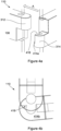
- Figures 4a and 4b illustrate how the door 102 and panel 104 are connected. Arrow A indicates the direction of movement required for assembly.
- the door 102 is positioned such that the pin 116 which extends downwardly from the hinge portion 112 attached to the door 102 rests on the plate portion 414a of the hinge portion 114 attached to the panel 104 from which the door 102 is to be hinged.
- the door 102 is angled such that the flattened sides of the pin 116 align with the narrow opening 418 to the indentation 416 of the hinge portion 114.
- the angle of the door 102 relative to the panel 104 can be changed by rotation whilst allowing the plate portion 414a to support some or all of the weight of the door 102.
- the door 102 can then be pushed horizontally such that the pin 116 slots into the indentation 416.
- the pin 116 is positioned such that the door 102 is in an open position when the pin aligns with the narrow opening 418. This may facilitate access to lift and appropriately angle the door 102. Closing the door 102 then engages the hinge assembly 110 such that the pin 116 cannot move horizontally out of the indentation 416 when the door is in the closed position.
- a locking plate 500 is then attached to the hinge portion 114 having the indentation 416 such that the pin 116 is no longer able to be moved horizontally out of the indentation 416 in any door position.
- two screws 502 are used to secure the locking plate 500 in place.
- securing means could be used, for example, more or fewer screws, welding, adhesive, a latch or the like, or any combination of the above.
- the locking plate 500 is inserted into position on the receiving portion 414a by movement in the direction marked by arrow B.
- the locking plate 500 is secured to the receiving portion 414b of the hinge portion 114.
- the outer vertical surface of the locking plate aligns with the outer vertical surface of the plate portion 414a, so providing a substantially smooth and continuous surface of the hinge portion 114.
- the hinge assembly fully supports the weight of the door such that the door does not need to be otherwise supported whilst the locking plate is attached. In this way, an individual can assemble the door 102 without requiring assistance.
- the method of assembling a door 102 therefore includes the steps of:
- That edge is arranged to be at least substantially perpendicular to the opening in step (2).
- the installer only needs to support the weight of the door 102 during step (1), which should be of short duration.
- the protruding portion of the hinge portion 114 may be supported by the receiving portion 414b as well as, or instead of, the pin 116 bearing the load.
- the method of removing a door 102 from its hinges therefore includes the steps of:
- two hinge assemblies 110, 120 are used.
- the hinge assemblies 110, 120 are oriented such that one of the hinge portions 112, 122 on the door 102 forms the upper hinge portion of its corresponding hinge assembly 110, 120 and the other hinge portion 122, 112 on the door 102 forms the lower hinge portion of its corresponding hinge assembly 120, 110.
- the door 102 cannot be lifted off its hinges, nor pulled downward off its hinges, as vertical movement in either direction is blocked by the hinge portions 114, 124 of the panel 104.
- This arrangement may be described as the two hinge assemblies 110, 120 being opposed.
- the pins 116, 126 protrude vertically from the hinge portions 112, 122 on the door, the pins 116, 126 therefore protrude in opposite directions.
- the locking plate 500 not only serves to prevent the pin 116 from becoming dislodged from the indentation, but also provides a self-closing mechanism for the door 102.
- the locking plate 500 is secured such that it is biased towards the opening 418 of the indentation 416.
- the locking plate 500 is arranged to lie flat across the opening 418 and in contact with the receiving portion 414b on both sides of the opening.
- the pin 116 When the flattened sides of the pin 116 are not parallel to the locking plate 500, i.e. when the door 102 is partially or fully open, the pin protrudes from the opening 416, pushing against the locking plate 500.
- the locking plate 500 therefore serves to bias the door 102 towards the closed position.
- this biasing mechanism holds the door open when it is opened beyond 90°. The same mechanism can therefore both close doors which have been left partially ajar, and keep open doors which have been deliberately opened wide, e.g. for cleaning or airing.
- the locking tab 500 has a protrusion 510 arranged, in use, to lie at least partially within the indentation 416.
- the pin 116 is therefore fully contained within the indentation 416 at all angles of rotation whilst still allowing the locking tab 500 to exert a force on the pin 116.
- the locking tab 500 as a whole may or may not be biased towards the pin 116 - in cases in which the locking tab 500 as a whole is not biased towards the pin 116, the protrusion 510 is biased towards the pin, for example by being spring-loaded.
- the hinge assembly 110 further includes a soft close device 600.
- the soft close device 600 has a moving portion 602 which is biased towards and in contact with the pin 116.
- the moving portion 602 provides an interference fit between the pin and the soft close device.
- the interference fit reduces the velocity of rotation of the pin 116 and therefore of the door 102, so avoiding the door 102 slamming shut.
- the resistance to rotation due to friction provided by the interference fit is less than the biasing due to the locking tab 500 such that the self-closing function provided by the locking tab 500 is achieved.
- the soft close device 600 has a tube 602 fitting closely within a cylinder in which it moves up and down against a liquid or gas, and so may be described as a piston.
- a tube 602 fitting closely within a cylinder in which it moves up and down against a liquid or gas, and so may be described as a piston.
- the skilled person would understand that the precise shape chosen is immaterial.
- no soft close device is used.
- the pin 116 is positioned vertically between the door 102 and the panel 104. There is therefore a small gap between the door 102 and the panel 104 when the door and panel lie parallel to each other.
- the pin 216 lies within the cross-sectional area of the door 202.
- the axis of rotation therefore also lies within the cross-sectional area of the door 202.
- the door 202 and the panel 204 each have indentations/cut-away portions in the region of the hinge assemblies.
- these indentations/cut-away portions are larger than those of the embodiments described above so as to allow more of the length of the protruding portions of each hinge portion 212, 214 to lie within the cross-sectional area of the door or panel.
- the pin 216 could lie within the cross-sectional area of the panel 204.
- the skilled person would understand that corresponding cut-out portions/indentations and protrusions in the door 202 and panel 204 would be needed in embodiments in which the pin lies within the cross-sectional area of the door 202 and of the panel 204.
- the locking plate 600 does not provide a self-closing mechanism.
- the locking plate 600 prevents the pin 216 from escaping from the indentation 218.
- the locking plate 600 may provide a self-closing mechanism as described above.
- the door 102, 202 and panel 104, 204 are made of glass. In alternative or additional embodiments, other materials such as metal and/or polymers such as Perspex may be used.
- the hinge assemblies 110, 210, 120, 220 are made of metal. In alternative or additional embodiments, other materials, for example polymers, may be used.
- the locking tab 500, 600 and the pin 116, 126 may be made of the same material or of a different material from the hinge portions 112, 114, 122, 124.
- Figure 12 shows a schematic view of a door panel 1202a.
- the door panel 1202a is substantially cuboid in shape and has a front face 1203 and a rear face 1205 which are of significantly larger surface area than any other face.
- Each face 1203, 1205 is planar and therefore lies in one particular plane.
- Each face 1203, 1205 may therefore be said to define a plane.
- edge 1207a-d Between the front and rear faces 1203, 1205 is an edge 1207a-d.
- the edge 1207a-d separates the planes defined by the two faces 1203, 1205.
- the door panel 1202b may be curved such that the edges 1207a-d are not separated from the faces 1203, 1205 by sharp corners but are instead continuous with the faces.
- each face 1203, 1205, although gently curved, will still be substantially planar to allow function as a door or panel and the skilled person would understand that a plane appropriate for each face can be determined from the widest point(s), as shown in Figure 12b .
- edge regions can be clearly identified by the skilled person and serve the same function.
- a hinge portion can therefore be attached in an edge region such that the axis of rotation lies adjacent to the edge region and between the planes defined by the faces.
- a hinge portion is attached to the door panel 1202a, 1202b such that the pin or other element defining an axis of rotation 1209a, 1209b is adjacent to, and at least substantially parallel to, an edge 1207a or edge region of the door panel 1202a, 1202b to which the hinge portion is connected.
- the axis of rotation 1209a, 1209b is arranged to lie between the planes defined by the two faces 1203, 1205.
- the specific hinge mechanism described is not the only mechanism which would permit the axis of rotation to lie between the planes defined by the two faces of a hinged panel and should not be taken to limit the other aspects of the invention, but rather as an example implementation which may offer further advantages.
- one or more circular, U-shaped or semi-circular hooks could be provided on one edge of a door, with the hook lying between the planes defined by the faces of the door or panel, as one hinge portion and one or more corresponding pins, arranged to accept the hooks, could be provided on the support or other panel to which the door is to be hingedly attached.
Landscapes
- Engineering & Computer Science (AREA)
- Mechanical Engineering (AREA)
- Health & Medical Sciences (AREA)
- Public Health (AREA)
- Epidemiology (AREA)
- General Health & Medical Sciences (AREA)
- Hinges (AREA)
Description
- This invention relates to a door hinge. The invention has particular but not exclusive application to hinge assembly for a shower door, to a shower cubicle employing the hinge assembly and to a method of installing a shower door using the hinge assembly. For convenience, the invention is discussed primarily in relation to shower cubicles.
- The skilled person will appreciate that other applications of the hinge are possible.
- A hinge assembly for a shower door panel is known from
US 5,867,869 , comprising a first and a second hinge portions, arranged, in use, such that the axis of rotation is adjacent to the side edge of the shower door panel and substantially between the front and rear faces of the shower door panel. - It is a desired aim of the invention to provide a door hinge assembly which allows a shower door panel to be more easily installed.
- It is another desired aim of the invention to provide a door hinge assembly which does not detract from the appearance of a shower cubicle.
- It is another desired aim of the invention to provide a frameless door hinge assembly. According to a first aspect of the invention, there is provided a door hinge assembly for a shower door panel having a front face, a rear face and a side edge between the front and rear faces, the door hinge assembly comprising a first hinge portion arranged, in use, to be attached to the side edge of the shower door panel, wherein the first hinge portion has a pin protruding vertically therefrom, and a second hinge portion arranged, in use, to be attached to a support and to cooperate with the first hinge portion so that the shower door panel can hinge between an open position and a closed position about an axis of rotation, wherein the second hinge portion has a vertical indentation or socket arranged, in use, to receive the pin, wherein the socket has a lateral opening to receive the pin, and a retainer member arranged, in use, to cover the opening to retain the pin in the socket, and wherein the socket is shaped to allow rotation of the pin within the socket, the first and second hinge portions being arranged, in use, such that the axis of rotation is adjacent to the side edge of the shower door panel and substantially between the front and rear faces of the shower door panel.
- The axis around which the panel is arranged, in use, to rotate may be referred to as the axis of the hinge or the axis of rotation.
- By locating the axis of rotation between the front and rear faces of the shower door panel, the axis of the hinge can be located in line with the panel and may provide a smoother, more aesthetically pleasing appearance in use.
- Optionally, the axis of rotation may be positioned equidistant from each of the front and rear faces of the shower door panel, such that the axis is arranged centrally with respect to a width of the shower door panel. Advantageously, the symmetrical arrangement may provide a more aesthetically pleasing appearance.
- According to a second aspect of the invention, there is provided a shower door comprising a panel and a hinge assembly, said panel having a front face, a rear face and a side edge between the front and rear face, said hinge assembly comprising a first hinge portion and a second hinge portion, said first hinge portion attached or attachable to the panel, the first hinge portion being arranged, in use, to allow rotation of the panel around an axis when the first hinge portion is coupled to the second hinge portion, the first hinge portion having a pin protruding vertically therefrom, wherein the second hinge portion has a vertical socket arranged, in use, to receive the pin, wherein the socket has a lateral opening to receive the pin, and a retainer member arranged, in use, to cover the opening to retain the pin in the socket, and wherein the socket is shaped to allow rotation of the pin within the socket, wherein the axis of rotation lies adjacent to the side edge and substantially between the front and rear faces of the panel.
- Optionally, a portion of the panel may be cut away or the panel may be shaped to have an indentation such that the axis lies within the footprint of the panel. In examples in which the axis lies within the footprint of the panel, some or all of the hinge portion may lie within the footprint of the panel. Advantageously, this may reduce the amount of space taken up by a hinge in addition to being aesthetically pleasing. Optionally, the hinged panel may have more than one hinge portion attached or attachable thereto. For example, two, three or four hinge portions may be present. Each hinge portion on a given side of the panel is arranged to allow rotation of the panel around the same axis. Advantageously, the use of multiple hinge portions provides multiple support points, so making the panel more stable in use and/or distributing the weight of the panel more evenly.
- According to a third aspect of the invention, there is provided a shower cubicle including a door hinge assembly for a shower door according to the first aspect of the invention, a shower door panel to which the first hinge portion is attached and a support to which the second hinge portion is attached.
- Optionally, the support may be another panel.
- By providing the locking tab for the lateral opening to the socket, the pin can be inserted through the lateral opening into the socket in a direction substantially transverse to the axis of the pin and the locking tab secured to close the opening and prevent the pin coming out of the socket through the lateral opening. In this way, a shower door provided with the hinge assembly can be installed by pushing the door horizontally into position.
- Optionally, the pin and socket may be configured so that the pin can pass through the lateral opening in a pre-determined angular position of the first and second hinge portions relative to each other. For example a transverse width of the pin may vary around a circumference of the pin so that the pin can pass through the lateral opening when a minimum width of the pin is aligned with the opening and is prevented from passing through the opening when the minimum width is non-aligned with the opening. In this way, a shower door provided with the hinge assembly can be installed by locating the door to align the minimum width of the pin with the lateral opening in the socket and pushing the door horizontally to insert the pin in the socket and then rotating the door so that the pin can no longer pass through the opening so as to hold the door in place whilst the locking tab is secured to cover the opening.
- Optionally, the cross-section of the pin has at least one flattened edge defining the minimum transverse width of the pin. In some embodiments, the pin may have two flattened edges, which may be opposite each other. The two flattened edges may be equal in size. In this way, the hinge may be non-handed.
- Optionally, the hinge assemblies are arranged such that the pin of one hinge assembly protrudes upwards and the pin of the other hinge assembly protrudes downwards. With this opposed arrangement of the hinge assemblies (i.e. the two pins pointing in opposite directions), the door cannot be lifted or lowered vertically so as to disengage the hinge assemblies.
- According to a fourth aspect of the invention, there is provided a method of installing a shower door panel using the door hinge assembly described above, the method including:
- (i) positioning the shower door panel such that the pins of the first hinge portions are aligned with the lateral openings to the sockets of the second hinge portions;
- (ii) moving the shower door panel horizontally such that the pins pass through the aligned lateral openings of the sockets; and
- (iii) securing the locking tabs across the lateral openings.
- The method may further comprise moving the shower door panel horizontally so that a minimum transverse width of at least one pin is aligned with and passes through the lateral opening of the socket and rotating the shower door panel such that the minimum transverse width of the at least one pin is not aligned with the lateral opening of the socket.
- Optionally, one pin protrudes vertically upwards and the other pin protrudes vertically downwards. Advantageously in such cases, the first hinge portion having the pin protruding vertically downwards is supported by the second hinge portion and the first hinge portion having the pin protruding vertically upwards supports the second hinge portion. Further, advantageously the first hinge portion having the pin protruding vertically downwards is the uppermost hinge assembly.
- The skilled person will appreciate that features discussed in relation to any one aspect of the invention may be provided with any other aspect of the invention.
- Embodiments of the invention will now be described in more detail by way of example only with reference to the accompanying drawings in which like reference numerals are used for like features:
-
Figure 1 is a view of a shower door assembly of an embodiment including two hinge assemblies; -
Figures 2a and 2b show close-up views of a hinge assembly ofFigure 1 ; -
Figure 2c shows a cross-sectional view of a hinge pin used in the embodiment ofFigures 1 and2a and 2b ; -
Figure 3 shows a door and a panel to which the door is arranged to be attached, arranged to form the shower door assembly ofFigure 1 ; -
Figures 4a and 4b show how the shower door assembly ofFigure 1 is assembled; -
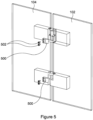
Figure 5 shows a schematic view of the shower door assembly ofFigure 1 illustrating the use of locking tabs; -
Figure 6 shows a close up of a hinge assembly according toFigure 5 ; -
Figure 7 shows the hinge assembly ofFigure 6 with the locking tab fully engaged; -
Figure 8 shows the completed shower door assembly corresponding toFigure 5 ; -
Figure 9 shows a cross-section of one of the hinge portions with a locking tab; -
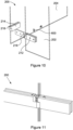
Figure 10 shows an exploded view of a shower door assembly of a second embodiment; -
Figure 11 shows a close-up of an assembled hinge assembly according to the embodiment ofFigure 10 ; -
Figure 12a shows a schematic perspective view of a hinged panel and its axis of rotation according to various embodiments of the invention; and -
Figure 12b shows a schematic plan view of a hinged panel and its axis of rotation according to various embodiments of the invention. - Referring to the drawings, a
shower door assembly 100 for a shower cubicle is shown. - The
shower door assembly 100 includes adoor panel 102, afixed panel 104 to which thedoor panel 102 is connected and twohinge assemblies panels panels panel 104 may be a wall or other surface or support. In alternative or additional embodiments, more than twohinge assemblies - In the embodiment being described, the
door panel 102 andfixed panel 104 are substantially flat rectangular panels having front and rear faces, opposed vertical side edges and opposed horizontal top and bottom edges. The hinge assemblies connect adjacent side edges of thepanels door panel 102 for hinging movement between an open position shown inFigure 1 and a closed position shown inFigure 5 . In the open position, thedoor panel 102 extends at an angle to the fixedpanel 104 to open an opening for access to and from a shower area. In the closed position, thedoor panel 102 is substantially aligned with fixedpanel 102 to close the opening to the shower area. - Each
hinge assembly hinge portions hinge portion door panel 102. Theother hinge portion panel 104. The skilled person would understand that it is immaterial which hinge portion of a pair is attached to thedoor panel 102 and which to the fixedpanel 104, provided that the pairs align and correspond. - Each
hinge portion body portion 106 arranged, in use, to be attached to thedoor panel 102 or the fixedpanel 104. In the embodiment being described, thedoor panel 102 and fixedpanel 104 are shaped such that thebody portion 106 slots around or into a portion of thedoor 102 orpanel 104. In some embodiments, thepanels hinge portion 112, 114,122,124. Advantageously, the indentations/cut-away portions allow at least a portion of the volume of the hinge portions to lie within the footprint of thedoor 102 andpanel 104. - The
body portion 106 has one edge which lies substantially parallel to, and near to, the edge of thedoor 102 orpanel 104 to which it is attached which is nearest to the intended hinge location. As such, the axis of rotation defined by the hinge is adjacent to, and at least substantially parallel to, that edge of thedoor 102 orpanel 104. - At the edge of each
body portion 106 nearest to the intended hinge location, eachhinge portion portion - In the embodiment being described,
hinge portion 112 has a vertical cavity andhinge portion 114 has a vertical indentation. In the embodiment being described, each protrudingportion door 102 orpanel 104 to which it is attached. As such, the axis of rotation defined by the hinge lies between the planes defined by the front and rear faces irrespective of whether or not the axis of rotation lies within the footprint of thedoor 102 orpanel 104. In this context, the footprint of the door or panel means the area covered by the door or panel, in particular the floor-space covered by the door/panel itself during use. - In the embodiment being described,
hinge portion 112 has its protrudingportion 312 in an upper portion of thehinge portion 112 and may be described as the upper hinge portion.Hinge portion 114 has its protrudingportion 314 in a lower portion of thehinge portion 114 and may be described as a lower hinge portion. The protruding portions are arranged to correspond such that, in use, the protruding portion of onehinge portion 112 rests on the protruding portion of thecorresponding hinge portion 114. - The skilled person would understand that it is immaterial which hinge
portion 112, 1114 is attached to thedoor 102 and which to thepanel 104, and which hinge portion is the upper section and which is the lower section. - The cavity of the
upper hinge portion 112 extends from the bottom of the protruding portion upwards into the protruding portion. - The indentation of the
lower hinge portion 114 extends from the top of the protruding portion downwards into the protruding portion. - In the embodiment being described, the protruding portions of the upper 112 and lower 114 hinge portions have substantially the same maximum cross section.
- In the embodiment being described, the protruding
portion 314 of thelower hinge portion 114 has two portions which are integral- aplate portion 414a and a receivingportion 414b. Theplate portion 414a is an at least substantially flat and horizontal portion at the lower side of thehinge portion 114. Theplate portion 414a has at least substantially the same cross-sectional area and shape as theupper hinge portion 112. - The receiving
portion 414b extends upwards from theplate portion 414a. The receivingportion 414b includes the vertical indentation orsocket 416, which is positioned substantially on a midline of the protrudingportion 314. Theplate portion 414a provides a ledge which is at least partially not covered by the receivingportion 414b and theindentation 416. In the embodiment being described, the receivingportion 414b has a smaller cross-sectional area than theplate 414a, and the edge of the receiving portion aligns with the edge of the plate except in the region of the ledge. - In alternative or additional embodiments wherein the hinge portion with the
indentation 416 rests on top of a hinge portion with a cavity, the hinge portion with the cavity supports the receivingportion 414b. In such embodiments, theplate portion 414a is not necessary to support thedoor 102 and may not be present. However, for reasons of aesthetics and consistency of manufacture, theplate portion 414a may be provided even when not required in use. Further, theplate portion 414a may serve as a guide to installers even when not used for support. - In use, the cavity and the
indentation 416 are arranged to align vertically. - Each
hinge assembly pin 116.Hinge portion 114 is drawn to be transparent inFigure 1 to allow thepin 116 to be seen. Anequivalent pin 126 is present within thehinge assembly 120 but is not visible inFigure 1 due to being obscured by thehinge portions pin - The
pin 116 is arranged to fit into both hingeportions hinge assembly 110 together. Thepin 116 sits within the cavity of onehinge portion 112 and within theindentation 416 of theother hinge portion 114. - In alternative embodiments, the
pin 116 is integral with one of thehinge portions other hinge portion pin 116 which protrudes from the first hinge portion. In such embodiments, a cavity is not needed. -
Figure 2c shows a cross-sectional view of thepin 116. Thepin 116 is substantially cylindrical, with two opposite sections cut away such that two sides of thepin 116 are flattened. In the embodiment shown, each flattened edge reduces the width of the pin by approximately 1/12. For example, for apin 116 with an effective diameter of 12mm for the circular portion, each flattened edge would take off 1mm such that the width at the narrowest point is 10mm. Preferably, the reduction in width is small enough to allow reasonably smooth rotation of the pin whilst being large enough to see by eye where the flattened areas are. In alternative or additional embodiments, each flattened edge may reduce the width by between 1/16 and 1/6 of the effective diameter. The effective diameter of thepin 116 may be between 2mm and 30mm, and preferably between 5mm and 20mm. - In embodiments having a cavity in one
hinge portion 112, the cavity is shaped to receive thepin 116. Advantageously, in at least some embodiments, the cavity is arranged such that thepin 116 cannot rotate within the cavity. - In embodiments not having a cavity, the
pin 116 is integral with, and extends from, thehinge portion 112. - The
hinge portion 112 with thepin 116 extending therefrom may be referred to as a male hinge portion. - The
indentation 416 in thehinge portion 114 is arranged to receive the section of thepin 116 which extends from theother hinge portion 112. Theindentation 416 has anopening 418 which is narrower than the widest point of the indentation and narrower than the diameter of thepin 116, such that the flattened edges of thepin 116 must be correctly aligned to allow thepin 116 to be pushed into the indentation horizontally. - The
hinge portion 114 with anindentation 416 arranged to receive thepin 116 may be referred to as a female hinge portion. - In the embodiment being described, the
opening 418 is approximately 11mm wide, so allowing the narrowest pin width of 10mm to comfortably enter theindentation 416 whilst preventing the widest pin width of 12mm from doing so. The skilled person would understand that the minimum width for the opening is the narrowest pin width and the maximum width for the opening is slightly smaller than the maximum pin width/the effective diameter of the circular portion of thepin 116. - The
indentation 416 is shaped to allow rotation of thepin 116 within the indentation. In alternative embodiments, the cavity may be arranged to allow rotation of thepin 116 and theindentation 416 may be arranged not to allow rotation of the pin. -
Figure 3 shows adoor 102 and aseparate panel 104, each provided with preassembled hinges as described above. Again, the axis of rotation lies adjacent to, and substantially parallel to, an edge of the door/panel to which the hinge is attached, and between the planes defined by the front and rear faces of the door/panel. -
Figures 4a and 4b illustrate how thedoor 102 andpanel 104 are connected. Arrow A indicates the direction of movement required for assembly. - To assemble a door according to the embodiment being described, the
door 102 is positioned such that thepin 116 which extends downwardly from thehinge portion 112 attached to thedoor 102 rests on theplate portion 414a of thehinge portion 114 attached to thepanel 104 from which thedoor 102 is to be hinged. - The
door 102 is angled such that the flattened sides of thepin 116 align with thenarrow opening 418 to theindentation 416 of thehinge portion 114. Advantageously, the angle of thedoor 102 relative to thepanel 104 can be changed by rotation whilst allowing theplate portion 414a to support some or all of the weight of thedoor 102. Thedoor 102 can then be pushed horizontally such that thepin 116 slots into theindentation 416. - Advantageously, the
pin 116 is positioned such that thedoor 102 is in an open position when the pin aligns with thenarrow opening 418. This may facilitate access to lift and appropriately angle thedoor 102. Closing thedoor 102 then engages thehinge assembly 110 such that thepin 116 cannot move horizontally out of theindentation 416 when the door is in the closed position. - A locking
plate 500 is then attached to thehinge portion 114 having theindentation 416 such that thepin 116 is no longer able to be moved horizontally out of theindentation 416 in any door position. In the embodiment being described, twoscrews 502 are used to secure thelocking plate 500 in place. The skilled person would understand that other securing means could be used, for example, more or fewer screws, welding, adhesive, a latch or the like, or any combination of the above. - In the embodiment shown in
Figure 6 , the lockingplate 500 is inserted into position on the receivingportion 414a by movement in the direction marked by arrow B. - In the embodiments being described, the locking
plate 500 is secured to the receivingportion 414b of thehinge portion 114. In these embodiments, the outer vertical surface of the locking plate aligns with the outer vertical surface of theplate portion 414a, so providing a substantially smooth and continuous surface of thehinge portion 114. - Advantageously, the hinge assembly fully supports the weight of the door such that the door does not need to be otherwise supported whilst the locking plate is attached. In this way, an individual can assemble the
door 102 without requiring assistance. - The method of assembling a
door 102 therefore includes the steps of: - 1. Positioning the
door 102 such that the end of thepin 116 rests on theplate portion 414a of thecorresponding hinge portion 114; - 2. Rotating the
door 102 such that the flattened edges of thepin 116 align with theopening 418 of theindentation 416; - 3. Sliding the
door 102 horizontally such that thepin 116 fits within theindentation 416; - 4. Rotating the
door 102 such that the flattened edges of thepin 116 do not align with theopening 418 of theindentation 416; and - 5. Securing a
locking plate 500 across theopening 418. - In embodiments in which the pin has only one flattened edge, that edge is arranged to be at least substantially perpendicular to the opening in step (2).
- Advantageously, the installer only needs to support the weight of the
door 102 during step (1), which should be of short duration. - In additional or alternative embodiments, the protruding portion of the
hinge portion 114 may be supported by the receivingportion 414b as well as, or instead of, thepin 116 bearing the load. - Correspondingly, the method of removing a
door 102 from its hinges therefore includes the steps of: - 1. Rotating the
door 102 such that the flattened edges of thepin 116 do not align with theopening 418 of the indentation 416 (advantageously, in this position, the locking tab is not necessary to keep the pin locked in place); - 2. Removing the locking
plate 500 across theopening 418; - 3. Rotating the
door 102 such that the flattened edges of thepin 116 align with theopening 418 of theindentation 416; - 4. Sliding the
door 102 horizontally such that thepin 116 slides out of the indentation 416 (the weight of the door advantageously still being supported at this point); and - 5. Removing the
door 102 from the doorway. - In the embodiment being described, two
hinge assemblies hinge assemblies hinge portions door 102 forms the upper hinge portion of itscorresponding hinge assembly other hinge portion door 102 forms the lower hinge portion of itscorresponding hinge assembly door 102 cannot be lifted off its hinges, nor pulled downward off its hinges, as vertical movement in either direction is blocked by thehinge portions panel 104. This arrangement may be described as the twohinge assemblies - In the embodiment shown in the figures wherein the
pins hinge portions pins - In at least some embodiments of the invention, the locking
plate 500 not only serves to prevent thepin 116 from becoming dislodged from the indentation, but also provides a self-closing mechanism for thedoor 102. - In these embodiments, the locking
plate 500 is secured such that it is biased towards the opening 418 of theindentation 416. In particular, the lockingplate 500 is arranged to lie flat across theopening 418 and in contact with the receivingportion 414b on both sides of the opening. - When the flattened sides of the
pin 116 are parallel to thelocking plate 500, which is the closed position of thedoor 102 in these embodiments, the pin lies fully within theindentation 416. - When the flattened sides of the
pin 116 are not parallel to thelocking plate 500, i.e. when thedoor 102 is partially or fully open, the pin protrudes from theopening 416, pushing against the lockingplate 500. The lockingplate 500 therefore serves to bias thedoor 102 towards the closed position. In embodiments wherein thedoor 102 can be opened by more than 90°, this biasing mechanism holds the door open when it is opened beyond 90°. The same mechanism can therefore both close doors which have been left partially ajar, and keep open doors which have been deliberately opened wide, e.g. for cleaning or airing. - In at least some embodiments, the
locking tab 500 has aprotrusion 510 arranged, in use, to lie at least partially within theindentation 416. Advantageously, thepin 116 is therefore fully contained within theindentation 416 at all angles of rotation whilst still allowing thelocking tab 500 to exert a force on thepin 116. In such cases, thelocking tab 500 as a whole may or may not be biased towards the pin 116 - in cases in which thelocking tab 500 as a whole is not biased towards thepin 116, theprotrusion 510 is biased towards the pin, for example by being spring-loaded. - In the embodiment shown in
Figure 6 , thehinge assembly 110 further includes a softclose device 600. The softclose device 600 has a movingportion 602 which is biased towards and in contact with thepin 116. The movingportion 602 provides an interference fit between the pin and the soft close device. Advantageously, the interference fit reduces the velocity of rotation of thepin 116 and therefore of thedoor 102, so avoiding thedoor 102 slamming shut. Preferably, the resistance to rotation due to friction provided by the interference fit is less than the biasing due to thelocking tab 500 such that the self-closing function provided by thelocking tab 500 is achieved. - In the embodiment shown, the soft
close device 600 has atube 602 fitting closely within a cylinder in which it moves up and down against a liquid or gas, and so may be described as a piston. The skilled person would understand that the precise shape chosen is immaterial. - In alternative embodiments, no soft close device is used.
- In the embodiments described with respect to
Figures 1 to 9 , thepin 116 is positioned vertically between thedoor 102 and thepanel 104. There is therefore a small gap between thedoor 102 and thepanel 104 when the door and panel lie parallel to each other. - In some cases, it may be advantageous to reduce this gap. The embodiment shown in
Figures 10 and 11 is one example of how this can be achieved. Like reference numerals are used to reference like features; with 102 and 202 both denoting doors, for example. - In the embodiment shown in
Figures 10 and 11 , thepin 216 lies within the cross-sectional area of thedoor 202. The axis of rotation therefore also lies within the cross-sectional area of thedoor 202. Thedoor 202 and thepanel 204 each have indentations/cut-away portions in the region of the hinge assemblies. For hinge assemblies of equivalent size, these indentations/cut-away portions are larger than those of the embodiments described above so as to allow more of the length of the protruding portions of eachhinge portion - In alternative or additional embodiments, the
pin 216 could lie within the cross-sectional area of thepanel 204. The skilled person would understand that corresponding cut-out portions/indentations and protrusions in thedoor 202 andpanel 204 would be needed in embodiments in which the pin lies within the cross-sectional area of thedoor 202 and of thepanel 204. - In the embodiment shown in
Figures 10 and 11 , the lockingplate 600 does not provide a self-closing mechanism. The lockingplate 600 prevents thepin 216 from escaping from theindentation 218. In alternative embodiments, the lockingplate 600 may provide a self-closing mechanism as described above. - In the embodiments being described, the
door panel - In the embodiments being described, the
hinge assemblies locking tab pin hinge portions -
Figure 12 shows a schematic view of adoor panel 1202a. Thedoor panel 1202a is substantially cuboid in shape and has afront face 1203 and arear face 1205 which are of significantly larger surface area than any other face. Eachface face - Between the front and
rear faces edge 1207a-d. Theedge 1207a-d separates the planes defined by the twofaces - In alternative embodiments, the
door panel 1202b may be curved such that theedges 1207a-d are not separated from thefaces face Figure 12b . Further, although theedges 1207a-d are continuous with the faces, edge regions can be clearly identified by the skilled person and serve the same function. A hinge portion can therefore be attached in an edge region such that the axis of rotation lies adjacent to the edge region and between the planes defined by the faces. - In use, a hinge portion is attached to the
door panel rotation edge 1207a or edge region of thedoor panel rotation faces - It will be understood that the invention is not limited to the embodiments above-described and the skilled person will appreciate that modifications can be made within the scope of the invention as defined by the claims.
- In particular, the specific hinge mechanism described is not the only mechanism which would permit the axis of rotation to lie between the planes defined by the two faces of a hinged panel and should not be taken to limit the other aspects of the invention, but rather as an example implementation which may offer further advantages. For example, one or more circular, U-shaped or semi-circular hooks could be provided on one edge of a door, with the hook lying between the planes defined by the faces of the door or panel, as one hinge portion and one or more corresponding pins, arranged to accept the hooks, could be provided on the support or other panel to which the door is to be hingedly attached.
Claims (15)
- A hinge assembly (110, 120) for a shower door panel (102) having a front face, a rear face and a side edge between the front and rear faces, the door hinge assembly (110; 120) comprising:a first hinge portion (112; 122) arranged, in use, to be attached to the side edge of the shower door panel (102), wherein the first hinge portion has a pin (116; 126) protruding vertically therefrom, anda second hinge portion (114; 124) arranged, in use, to be attached to a support (104) and to cooperate with the first hinge portion (112; 122) so that the shower door panel (102) can hinge between an open position and a closed position about an axis of rotation, wherein the second hinge portion (114; 124) has a vertical socket (416) arranged, in use, to receive the pin (116; 126), wherein the socket (416) has a lateral opening (418) to receive the pin (116; 126), and a retainer member (500) arranged, in use, to cover the opening to retain the pin in the socket (416), and wherein the socket (416) is shaped to allow rotation of the pin within the socket,the first (112; 122) and second (114; 124) hinge portions being arranged, in use, such that the axis of rotation is adjacent to the side edge of the shower door panel (102) and substantially between the front and rear faces of the shower door panel (102).
- The assembly (110, 120) of claim 1 wherein the axis of rotation is positioned equidistant from each of the front and rear faces of the shower door panel (102), such that the axis is arranged centrally with respect to a width of the shower door panel.
- The assembly (110, 120) of claim 1 wherein the pin (116; 126) can be inserted through the lateral opening (418) into the socket (416) in a direction substantially transverse to the axis of the pin and the retainer member (500) secured to close the opening (418) and prevent the pin (116; 126) coming out of the socket (416) through the lateral opening (418).
- The assembly (110, 120) of any preceding claim wherein the pin (116; 126) and socket (416) are configured so that the pin (116; 126) can pass through the lateral opening (418) in a pre-determined angular position of the first (112; 122) and second (114; 124) hinge portions relative to each other.
- The assembly (110, 120) of claim 4 wherein a transverse width of the pin (116; 126) varies around a circumference of the pin so that the pin can pass through the lateral opening (418) when a minimum width of the pin is aligned with the opening and is prevented from passing through the opening when the minimum width is non-aligned with the opening, wherein optionally the cross-section of the pin (116; 126) has at least one flattened edge defining the minimum transverse width of the pin, and wherein further optionally the pin (116; 126) has two flattened edges opposite each other.
- A shower door (100) comprising a panel (102) and a hinge assembly (110, 120), said panel having a front face, a rear face and a side edge between the front and rear face, said hinge assembly comprising a first hinge portion (112; 122) and a second hinge portion (114; 124), said first hinge portion (114; 124) attached or attachable to the panel (102), the first hinge portion being arranged, in use, to allow rotation of the panel (102) around an axis when the first hinge portion is coupled to the second hinge portion (112; 122), the first hinge portion (112; 122) having a pin (116; 126) protruding vertically therefrom, wherein the second hinge portion (114; 124) has a vertical socket (416) arranged, in use, to receive the pin (116; 126), wherein the socket has a lateral opening (418) to receive the pin, and a retainer member (500) arranged, in use, to cover the opening (418) to retain the pin in the socket, and wherein the socket (416) is shaped to allow rotation of the pin (116; 126) within the socket, and wherein the axis of rotation lies adjacent to the side edge and substantially between the front and rear faces of the panel (102).
- The shower door (100) of claim 6 wherein a portion of the panel (102) is cut away or the panel (102) is shaped to have an indentation such that the axis lies within the footprint of the panel.
- The shower door (100) of claim 6 or claim 7 wherein, the panel (102) has more than one hinge portion (114; 124; 112; 122) attached or attachable thereto.
- A shower cubicle (100) including: a door panel (102), a fixed panel (104), and at least two hinge assemblies (110, 120) according to any of claims 1 to 5, wherein the hinge assemblies (110, 120) connect the door panel (102) to the fixed panel (104) for movement relative to the fixed panel.
- The shower cubicle (100) according to claim 9 wherein the hinge assemblies (110, 120) are arranged such that the pin (116) of one hinge assembly (110) protrudes upwards and the pin (126) of the other hinge assembly (120) protrudes downwards.
- A method of installing a shower door panel (102) using a door hinge assembly (110; 120) comprising a first hinge portion (112; 122) comprising a pin (116; 126) protruding vertically therefrom and arranged, in use, to be attached to the side edge of the shower door panel (102), and a second hinge portion (114; 124) wherein the second hinge portion has a vertical socket (416) arranged, in use, to receive the pin (116, 126), wherein the socket has a lateral opening (418) to receive the pin, and a retainer member (500) arranged, in use, to cover the opening to retain the pin in the socket, and wherein the socket (416) is shaped to allow rotation of the pin (116; 126) within the socket, the second hinge portion (114; 124) being arranged, in use, to be attached to a support (104) and to cooperate with the first hinge portion (112; 122) so that the shower door panel (102) can hinge between an open position and a closed position about an axis of rotation, the method including:(i) positioning the shower door panel (102) such that the pin (116; 126) of the first hinge portion (112; 122) is aligned with the lateral opening (418) to the socket (416) of the second hinge portion (114; 124);(ii) moving the shower door panel (102) horizontally such that the pin (418) passes through the aligned lateral opening (418) of the socket (416); and(iii) securing a retainer member (500) across the lateral opening (418).
- The method of claim 11 wherein the pin (116; 126) has a minimum transverse width of that is aligned with the lateral opening (418) of the socket (416) in a first orientation of the pin (116; 126) relative to the opening (418) and is not aligned with the lateral opening (418) of the socket (416) in a second orientation of the pin (116; 126) relative to the lateral opening (418) of the socket (416), the first and second orientations being angularly spaced apart.
- The method of claim 11 or claim 12 wherein the shower door panel (102) is installed with two or more hinge assemblies (110; 120).
- The method of claim 13 wherein the pin (116) of a first hinge assembly (110) protrudes vertically upwards and the pin (126) of a second hinge assembly (120) protrudes vertically downwards.
- The method of claim 14 wherein the second hinge assembly (120) having the pin (126) protruding vertically downwards is the uppermost hinge assembly.
Applications Claiming Priority (2)
| Application Number | Priority Date | Filing Date | Title |
|---|---|---|---|
| GB1615220.9A GB2553545B (en) | 2016-09-07 | 2016-09-07 | Door hinge |
| PCT/GB2017/052158 WO2018046880A1 (en) | 2016-09-07 | 2017-07-24 | Door hinge |
Publications (2)
| Publication Number | Publication Date |
|---|---|
| EP3510222A1 EP3510222A1 (en) | 2019-07-17 |
| EP3510222B1 true EP3510222B1 (en) | 2023-09-27 |
Family
ID=57139839
Family Applications (1)
| Application Number | Title | Priority Date | Filing Date |
|---|---|---|---|
| EP17748864.0A Active EP3510222B1 (en) | 2016-09-07 | 2017-07-24 | Door hinge |
Country Status (5)
| Country | Link |
|---|---|
| US (1) | US20210196085A1 (en) |
| EP (1) | EP3510222B1 (en) |
| CN (1) | CN109690004A (en) |
| GB (1) | GB2553545B (en) |
| WO (1) | WO2018046880A1 (en) |
Families Citing this family (14)
| Publication number | Priority date | Publication date | Assignee | Title |
|---|---|---|---|---|
| CN107419980B (en) * | 2017-08-30 | 2022-10-28 | 福建西河卫浴科技有限公司 | Seamless lifting hinge structure |
| CN109936649B (en) * | 2019-02-22 | 2020-09-08 | 维沃移动通信有限公司 | Connecting assembly and mobile terminal |
| KR102619231B1 (en) * | 2019-05-28 | 2023-12-29 | 주식회사 경동나비엔 | Detachable hinge |
| US12037829B2 (en) * | 2019-06-03 | 2024-07-16 | Colcom Group S.P.A. | Hinge for the rotatable movement of a door, a leaf or the like and system for fixing the latter to a stationary supporting structure |
| US11661776B2 (en) * | 2020-03-17 | 2023-05-30 | Vutility, Inc. | Housing for an electrical device |
| CA3131951A1 (en) * | 2020-09-24 | 2022-03-24 | Fgx International Inc. | Universal cam action hinge and fastener with detent |
| US12123237B2 (en) * | 2021-03-05 | 2024-10-22 | Hoffman Enclosures Inc. | Systems and methods for a hinge |
| US12168905B2 (en) * | 2021-03-17 | 2024-12-17 | William Clifford Houser | Swing gate mechanism to swing open an overhead lift gate |
| CA3163596A1 (en) | 2021-06-17 | 2022-12-17 | Fgx International Inc. | Eyewear case and packaging system having improved hang tab |
| US11905750B2 (en) * | 2021-06-23 | 2024-02-20 | Teijin Automotive Technologies, Inc. | Releasable hinge assembly |
| JP7018568B1 (en) * | 2021-08-26 | 2022-02-14 | パナソニックIpマネジメント株式会社 | An opening / closing structure for an outlet in an electronic device and an electronic device provided with the opening / closing structure. |
| CN216960402U (en) * | 2021-11-03 | 2022-07-12 | 华为技术有限公司 | Damping pin and cabinet |
| CN114992963B (en) * | 2022-05-11 | 2025-05-27 | 宁波婷微电子科技有限公司 | A handle system with a reinforced shaft and a vehicle refrigerator using the same |
| US12601212B2 (en) * | 2023-05-31 | 2026-04-14 | Fca Us Llc | Vehicle door hinge |
Family Cites Families (17)
| Publication number | Priority date | Publication date | Assignee | Title |
|---|---|---|---|---|
| FR2295205A1 (en) * | 1974-07-24 | 1976-07-16 | Pommier & Cie | Detachable hinge for rack - has tubular support extending through arc and accommodating pin with machined flat |
| CH660205A5 (en) * | 1984-01-24 | 1987-03-31 | Brotschi & Cie Ag Geb | ADJUSTABLE DOOR AND WINDOW TAPE. |
| DE3515416A1 (en) * | 1984-05-17 | 1985-11-21 | Walter Hinterkappelen Pfäffli | Hinge for doors with an overlap |
| US5867869A (en) * | 1994-10-06 | 1999-02-09 | Chmi | Pressure hinge device for glass door or panel |
| FR2748515B1 (en) * | 1996-05-09 | 1999-08-20 | Adler Sa | HINGE WITH ELASTIC RING RECALLING SYSTEM |
| AT411478B (en) * | 2000-09-25 | 2004-01-26 | Dana Tuerenindustrie | DOOR BAND |
| DE20300089U1 (en) * | 2003-01-07 | 2003-03-27 | Sun, Chung-Cheng, Tainan | Hinge for frameless door has spindle with bush interface and surrounding bush |
| DE202004008885U1 (en) * | 2004-06-04 | 2005-10-13 | Hüppe GmbH & Co. | Connector and seal for shower screens which acts as hinge has arms which fit into join between two sheets of glass making up pane |
| EP1626146A3 (en) * | 2004-08-11 | 2006-07-26 | Yehuda Barak | Hinge assembly |
| FR2886965B1 (en) * | 2005-06-10 | 2007-08-31 | Ko Ming Cheng | ADJUSTABLE HINGE FOR A GLASS DOOR |
| DE202006012415U1 (en) * | 2006-08-11 | 2006-11-23 | Schulte Duschkabinenbau Gmbh & Co. Kg | Hinge for swiveling door used in shower partition has retainer that is forked or laterally slides on hinge pin, and safety screw that runs parallel to swivel axis of swiveling door when tightened to secure and prevent retainer from rotating |
| US20120096677A1 (en) * | 2010-10-21 | 2012-04-26 | Jung-Yung Ho | Style of safety door hinge design |
| CN202249358U (en) * | 2011-08-31 | 2012-05-30 | 中山市莎丽卫浴设备有限公司 | Automatic-resetting buffering shower door |
| DE202012005692U1 (en) * | 2012-03-05 | 2012-07-09 | Schulte Duschkabinenbau Gmbh & Co. Kg | Fitting and shower enclosure |
| AT515718B1 (en) * | 2014-05-09 | 2017-02-15 | Tif Gmbh | Fitting for the pivotable mounting of a door leaf |
| CN204175071U (en) * | 2014-10-20 | 2015-02-25 | 蔡达锋 | A kind of shower cubicle hinge |
| DE102015112746B3 (en) * | 2015-08-03 | 2017-01-26 | Edmund Schuster | safety hinge |
-
2016
- 2016-09-07 GB GB1615220.9A patent/GB2553545B/en active Active
-
2017
- 2017-07-24 WO PCT/GB2017/052158 patent/WO2018046880A1/en not_active Ceased
- 2017-07-24 CN CN201780054654.4A patent/CN109690004A/en active Pending
- 2017-07-24 US US16/328,422 patent/US20210196085A1/en not_active Abandoned
- 2017-07-24 EP EP17748864.0A patent/EP3510222B1/en active Active
Also Published As
| Publication number | Publication date |
|---|---|
| EP3510222A1 (en) | 2019-07-17 |
| WO2018046880A1 (en) | 2018-03-15 |
| GB2553545B (en) | 2021-08-11 |
| US20210196085A1 (en) | 2021-07-01 |
| CN109690004A (en) | 2019-04-26 |
| GB201615220D0 (en) | 2016-10-19 |
| GB2553545A (en) | 2018-03-14 |
Similar Documents
| Publication | Publication Date | Title |
|---|---|---|
| WO2018046880A1 (en) | Door hinge | |
| EP3075940B1 (en) | Corner connection device of shower door track, shower door frame and shower door | |
| US4389748A (en) | Concealed door hinge | |
| US7559114B2 (en) | Hinge attachable door stop insert | |
| US20130104345A1 (en) | Hinge with integral stop | |
| KR101968628B1 (en) | Pivot hinge apparatus | |
| JP2005146625A (en) | Hinge device | |
| EP2886480B1 (en) | Container with hidden hinge and hinge fixing structure therefor | |
| US20070151164A1 (en) | Continuous hinge for swing door | |
| EA034304B1 (en) | Low-bulkiness hinge | |
| KR20130036853A (en) | Door hinge for protecting finger with ease of installation and door system using the same | |
| CN108952225B (en) | A simple shower room | |
| KR102429577B1 (en) | Finger pinch prevention door | |
| KR102315507B1 (en) | Hinge with improved installation convenience and hand pinch preventing device using thereof | |
| GB2553733A (en) | Door hinge | |
| KR20120041388A (en) | Hinge for up and down retractable furniture door | |
| KR20130019162A (en) | Door hinge | |
| KR102458496B1 (en) | Preventing device for hand pinching in door gap with improved installation convenience | |
| EP1635009A2 (en) | Hinged wall access panel | |
| KR200473952Y1 (en) | Hinge bracket For folding door | |
| KR200173295Y1 (en) | Door hinge | |
| KR101137823B1 (en) | Hinged door | |
| KR101610864B1 (en) | Door handle for folding door | |
| JP5627115B2 (en) | Joinery | |
| EP3067503B1 (en) | Shower door system, and assembly therefor |
Legal Events
| Date | Code | Title | Description |
|---|---|---|---|
| STAA | Information on the status of an ep patent application or granted ep patent |
Free format text: STATUS: UNKNOWN |
|
| STAA | Information on the status of an ep patent application or granted ep patent |
Free format text: STATUS: THE INTERNATIONAL PUBLICATION HAS BEEN MADE |
|
| PUAI | Public reference made under article 153(3) epc to a published international application that has entered the european phase |
Free format text: ORIGINAL CODE: 0009012 |
|
| STAA | Information on the status of an ep patent application or granted ep patent |
Free format text: STATUS: REQUEST FOR EXAMINATION WAS MADE |
|
| 17P | Request for examination filed |
Effective date: 20190228 |
|
| AK | Designated contracting states |
Kind code of ref document: A1 Designated state(s): AL AT BE BG CH CY CZ DE DK EE ES FI FR GB GR HR HU IE IS IT LI LT LU LV MC MK MT NL NO PL PT RO RS SE SI SK SM TR |
|
| AX | Request for extension of the european patent |
Extension state: BA ME |
|
| DAV | Request for validation of the european patent (deleted) | ||
| DAX | Request for extension of the european patent (deleted) | ||
| GRAP | Despatch of communication of intention to grant a patent |
Free format text: ORIGINAL CODE: EPIDOSNIGR1 |
|
| STAA | Information on the status of an ep patent application or granted ep patent |
Free format text: STATUS: GRANT OF PATENT IS INTENDED |
|
| INTG | Intention to grant announced |
Effective date: 20230616 |
|
| GRAS | Grant fee paid |
Free format text: ORIGINAL CODE: EPIDOSNIGR3 |
|
| GRAA | (expected) grant |
Free format text: ORIGINAL CODE: 0009210 |
|
| STAA | Information on the status of an ep patent application or granted ep patent |
Free format text: STATUS: THE PATENT HAS BEEN GRANTED |
|
| AK | Designated contracting states |
Kind code of ref document: B1 Designated state(s): AL AT BE BG CH CY CZ DE DK EE ES FI FR GB GR HR HU IE IS IT LI LT LU LV MC MK MT NL NO PL PT RO RS SE SI SK SM TR |
|
| REG | Reference to a national code |
Ref country code: GB Ref legal event code: FG4D |
|
| RIN1 | Information on inventor provided before grant (corrected) |
Inventor name: NAKOS, CHRISTOS Inventor name: DAVIS, SCOTT Inventor name: PLACENCIA, ADOLFO |
|
| REG | Reference to a national code |
Ref country code: CH Ref legal event code: EP |
|
| REG | Reference to a national code |
Ref country code: DE Ref legal event code: R096 Ref document number: 602017074660 Country of ref document: DE |
|
| REG | Reference to a national code |
Ref country code: IE Ref legal event code: FG4D |
|
| P01 | Opt-out of the competence of the unified patent court (upc) registered |
Effective date: 20230927 |
|
| REG | Reference to a national code |
Ref country code: LT Ref legal event code: MG9D |
|
| PG25 | Lapsed in a contracting state [announced via postgrant information from national office to epo] |
Ref country code: GR Free format text: LAPSE BECAUSE OF FAILURE TO SUBMIT A TRANSLATION OF THE DESCRIPTION OR TO PAY THE FEE WITHIN THE PRESCRIBED TIME-LIMIT Effective date: 20231228 |
|
| PG25 | Lapsed in a contracting state [announced via postgrant information from national office to epo] |
Ref country code: SE Free format text: LAPSE BECAUSE OF FAILURE TO SUBMIT A TRANSLATION OF THE DESCRIPTION OR TO PAY THE FEE WITHIN THE PRESCRIBED TIME-LIMIT Effective date: 20230927 Ref country code: RS Free format text: LAPSE BECAUSE OF FAILURE TO SUBMIT A TRANSLATION OF THE DESCRIPTION OR TO PAY THE FEE WITHIN THE PRESCRIBED TIME-LIMIT Effective date: 20230927 Ref country code: NO Free format text: LAPSE BECAUSE OF FAILURE TO SUBMIT A TRANSLATION OF THE DESCRIPTION OR TO PAY THE FEE WITHIN THE PRESCRIBED TIME-LIMIT Effective date: 20231227 Ref country code: LV Free format text: LAPSE BECAUSE OF FAILURE TO SUBMIT A TRANSLATION OF THE DESCRIPTION OR TO PAY THE FEE WITHIN THE PRESCRIBED TIME-LIMIT Effective date: 20230927 Ref country code: LT Free format text: LAPSE BECAUSE OF FAILURE TO SUBMIT A TRANSLATION OF THE DESCRIPTION OR TO PAY THE FEE WITHIN THE PRESCRIBED TIME-LIMIT Effective date: 20230927 Ref country code: HR Free format text: LAPSE BECAUSE OF FAILURE TO SUBMIT A TRANSLATION OF THE DESCRIPTION OR TO PAY THE FEE WITHIN THE PRESCRIBED TIME-LIMIT Effective date: 20230927 Ref country code: GR Free format text: LAPSE BECAUSE OF FAILURE TO SUBMIT A TRANSLATION OF THE DESCRIPTION OR TO PAY THE FEE WITHIN THE PRESCRIBED TIME-LIMIT Effective date: 20231228 Ref country code: FI Free format text: LAPSE BECAUSE OF FAILURE TO SUBMIT A TRANSLATION OF THE DESCRIPTION OR TO PAY THE FEE WITHIN THE PRESCRIBED TIME-LIMIT Effective date: 20230927 |
|
| REG | Reference to a national code |
Ref country code: NL Ref legal event code: MP Effective date: 20230927 |
|
| REG | Reference to a national code |
Ref country code: AT Ref legal event code: MK05 Ref document number: 1615580 Country of ref document: AT Kind code of ref document: T Effective date: 20230927 |
|
| PG25 | Lapsed in a contracting state [announced via postgrant information from national office to epo] |
Ref country code: NL Free format text: LAPSE BECAUSE OF FAILURE TO SUBMIT A TRANSLATION OF THE DESCRIPTION OR TO PAY THE FEE WITHIN THE PRESCRIBED TIME-LIMIT Effective date: 20230927 |
|
| PG25 | Lapsed in a contracting state [announced via postgrant information from national office to epo] |
Ref country code: IS Free format text: LAPSE BECAUSE OF FAILURE TO SUBMIT A TRANSLATION OF THE DESCRIPTION OR TO PAY THE FEE WITHIN THE PRESCRIBED TIME-LIMIT Effective date: 20240127 |
|
| PG25 | Lapsed in a contracting state [announced via postgrant information from national office to epo] |
Ref country code: AT Free format text: LAPSE BECAUSE OF FAILURE TO SUBMIT A TRANSLATION OF THE DESCRIPTION OR TO PAY THE FEE WITHIN THE PRESCRIBED TIME-LIMIT Effective date: 20230927 |
|
| PG25 | Lapsed in a contracting state [announced via postgrant information from national office to epo] |
Ref country code: ES Free format text: LAPSE BECAUSE OF FAILURE TO SUBMIT A TRANSLATION OF THE DESCRIPTION OR TO PAY THE FEE WITHIN THE PRESCRIBED TIME-LIMIT Effective date: 20230927 |
|
| PG25 | Lapsed in a contracting state [announced via postgrant information from national office to epo] |
Ref country code: SM Free format text: LAPSE BECAUSE OF FAILURE TO SUBMIT A TRANSLATION OF THE DESCRIPTION OR TO PAY THE FEE WITHIN THE PRESCRIBED TIME-LIMIT Effective date: 20230927 Ref country code: RO Free format text: LAPSE BECAUSE OF FAILURE TO SUBMIT A TRANSLATION OF THE DESCRIPTION OR TO PAY THE FEE WITHIN THE PRESCRIBED TIME-LIMIT Effective date: 20230927 Ref country code: IS Free format text: LAPSE BECAUSE OF FAILURE TO SUBMIT A TRANSLATION OF THE DESCRIPTION OR TO PAY THE FEE WITHIN THE PRESCRIBED TIME-LIMIT Effective date: 20240127 Ref country code: ES Free format text: LAPSE BECAUSE OF FAILURE TO SUBMIT A TRANSLATION OF THE DESCRIPTION OR TO PAY THE FEE WITHIN THE PRESCRIBED TIME-LIMIT Effective date: 20230927 Ref country code: EE Free format text: LAPSE BECAUSE OF FAILURE TO SUBMIT A TRANSLATION OF THE DESCRIPTION OR TO PAY THE FEE WITHIN THE PRESCRIBED TIME-LIMIT Effective date: 20230927 Ref country code: CZ Free format text: LAPSE BECAUSE OF FAILURE TO SUBMIT A TRANSLATION OF THE DESCRIPTION OR TO PAY THE FEE WITHIN THE PRESCRIBED TIME-LIMIT Effective date: 20230927 Ref country code: AT Free format text: LAPSE BECAUSE OF FAILURE TO SUBMIT A TRANSLATION OF THE DESCRIPTION OR TO PAY THE FEE WITHIN THE PRESCRIBED TIME-LIMIT Effective date: 20230927 Ref country code: SK Free format text: LAPSE BECAUSE OF FAILURE TO SUBMIT A TRANSLATION OF THE DESCRIPTION OR TO PAY THE FEE WITHIN THE PRESCRIBED TIME-LIMIT Effective date: 20230927 Ref country code: PT Free format text: LAPSE BECAUSE OF FAILURE TO SUBMIT A TRANSLATION OF THE DESCRIPTION OR TO PAY THE FEE WITHIN THE PRESCRIBED TIME-LIMIT Effective date: 20240129 |
|
| PG25 | Lapsed in a contracting state [announced via postgrant information from national office to epo] |
Ref country code: PL Free format text: LAPSE BECAUSE OF FAILURE TO SUBMIT A TRANSLATION OF THE DESCRIPTION OR TO PAY THE FEE WITHIN THE PRESCRIBED TIME-LIMIT Effective date: 20230927 Ref country code: IT Free format text: LAPSE BECAUSE OF FAILURE TO SUBMIT A TRANSLATION OF THE DESCRIPTION OR TO PAY THE FEE WITHIN THE PRESCRIBED TIME-LIMIT Effective date: 20230927 |
|
| REG | Reference to a national code |
Ref country code: DE Ref legal event code: R097 Ref document number: 602017074660 Country of ref document: DE |
|
| PG25 | Lapsed in a contracting state [announced via postgrant information from national office to epo] |
Ref country code: DK Free format text: LAPSE BECAUSE OF FAILURE TO SUBMIT A TRANSLATION OF THE DESCRIPTION OR TO PAY THE FEE WITHIN THE PRESCRIBED TIME-LIMIT Effective date: 20230927 |
|
| PG25 | Lapsed in a contracting state [announced via postgrant information from national office to epo] |
Ref country code: DK Free format text: LAPSE BECAUSE OF FAILURE TO SUBMIT A TRANSLATION OF THE DESCRIPTION OR TO PAY THE FEE WITHIN THE PRESCRIBED TIME-LIMIT Effective date: 20230927 |
|
| PLBE | No opposition filed within time limit |
Free format text: ORIGINAL CODE: 0009261 |
|
| STAA | Information on the status of an ep patent application or granted ep patent |
Free format text: STATUS: NO OPPOSITION FILED WITHIN TIME LIMIT |
|
| 26N | No opposition filed |
Effective date: 20240628 |
|
| PGFP | Annual fee paid to national office [announced via postgrant information from national office to epo] |
Ref country code: FR Payment date: 20240725 Year of fee payment: 8 |
|
| PG25 | Lapsed in a contracting state [announced via postgrant information from national office to epo] |
Ref country code: SI Free format text: LAPSE BECAUSE OF FAILURE TO SUBMIT A TRANSLATION OF THE DESCRIPTION OR TO PAY THE FEE WITHIN THE PRESCRIBED TIME-LIMIT Effective date: 20230927 |
|
| PG25 | Lapsed in a contracting state [announced via postgrant information from national office to epo] |
Ref country code: SI Free format text: LAPSE BECAUSE OF FAILURE TO SUBMIT A TRANSLATION OF THE DESCRIPTION OR TO PAY THE FEE WITHIN THE PRESCRIBED TIME-LIMIT Effective date: 20230927 |
|
| PG25 | Lapsed in a contracting state [announced via postgrant information from national office to epo] |
Ref country code: BG Free format text: LAPSE BECAUSE OF FAILURE TO SUBMIT A TRANSLATION OF THE DESCRIPTION OR TO PAY THE FEE WITHIN THE PRESCRIBED TIME-LIMIT Effective date: 20230927 |
|
| PG25 | Lapsed in a contracting state [announced via postgrant information from national office to epo] |
Ref country code: BG Free format text: LAPSE BECAUSE OF FAILURE TO SUBMIT A TRANSLATION OF THE DESCRIPTION OR TO PAY THE FEE WITHIN THE PRESCRIBED TIME-LIMIT Effective date: 20230927 |
|
| PG25 | Lapsed in a contracting state [announced via postgrant information from national office to epo] |
Ref country code: MC Free format text: LAPSE BECAUSE OF FAILURE TO SUBMIT A TRANSLATION OF THE DESCRIPTION OR TO PAY THE FEE WITHIN THE PRESCRIBED TIME-LIMIT Effective date: 20230927 |
|
| REG | Reference to a national code |
Ref country code: CH Ref legal event code: PL |
|
| PG25 | Lapsed in a contracting state [announced via postgrant information from national office to epo] |
Ref country code: LU Free format text: LAPSE BECAUSE OF NON-PAYMENT OF DUE FEES Effective date: 20240724 |
|
| PG25 | Lapsed in a contracting state [announced via postgrant information from national office to epo] |
Ref country code: LU Free format text: LAPSE BECAUSE OF NON-PAYMENT OF DUE FEES Effective date: 20240724 |
|
| PG25 | Lapsed in a contracting state [announced via postgrant information from national office to epo] |
Ref country code: BE Free format text: LAPSE BECAUSE OF NON-PAYMENT OF DUE FEES Effective date: 20240731 Ref country code: CH Free format text: LAPSE BECAUSE OF NON-PAYMENT OF DUE FEES Effective date: 20240731 |
|
| REG | Reference to a national code |
Ref country code: BE Ref legal event code: MM Effective date: 20240731 |
|
| PGFP | Annual fee paid to national office [announced via postgrant information from national office to epo] |
Ref country code: DE Payment date: 20250728 Year of fee payment: 9 |
|
| PGFP | Annual fee paid to national office [announced via postgrant information from national office to epo] |
Ref country code: GB Payment date: 20250701 Year of fee payment: 9 |
|
| PGFP | Annual fee paid to national office [announced via postgrant information from national office to epo] |
Ref country code: IE Payment date: 20250718 Year of fee payment: 9 |
|
| PG25 | Lapsed in a contracting state [announced via postgrant information from national office to epo] |
Ref country code: CY Free format text: LAPSE BECAUSE OF FAILURE TO SUBMIT A TRANSLATION OF THE DESCRIPTION OR TO PAY THE FEE WITHIN THE PRESCRIBED TIME-LIMIT; INVALID AB INITIO Effective date: 20170724 |
|
| PG25 | Lapsed in a contracting state [announced via postgrant information from national office to epo] |
Ref country code: HU Free format text: LAPSE BECAUSE OF FAILURE TO SUBMIT A TRANSLATION OF THE DESCRIPTION OR TO PAY THE FEE WITHIN THE PRESCRIBED TIME-LIMIT; INVALID AB INITIO Effective date: 20170724 |
|
| PG25 | Lapsed in a contracting state [announced via postgrant information from national office to epo] |
Ref country code: FR Free format text: LAPSE BECAUSE OF NON-PAYMENT OF DUE FEES Effective date: 20250731 |