EP3510219B1 - Releasable latch - Google Patents
Releasable latch Download PDFInfo
- Publication number
- EP3510219B1 EP3510219B1 EP16915894.6A EP16915894A EP3510219B1 EP 3510219 B1 EP3510219 B1 EP 3510219B1 EP 16915894 A EP16915894 A EP 16915894A EP 3510219 B1 EP3510219 B1 EP 3510219B1
- Authority
- EP
- European Patent Office
- Prior art keywords
- rod
- latch
- channel
- relative
- latches
- Prior art date
- Legal status (The legal status is an assumption and is not a legal conclusion. Google has not performed a legal analysis and makes no representation as to the accuracy of the status listed.)
- Active
Links
Images


Classifications
-
- E—FIXED CONSTRUCTIONS
- E05—LOCKS; KEYS; WINDOW OR DOOR FITTINGS; SAFES
- E05C—BOLTS OR FASTENING DEVICES FOR WINGS, SPECIALLY FOR DOORS OR WINDOWS
- E05C9/00—Arrangements of simultaneously actuated bolts or other securing devices at well-separated positions on the same wing
- E05C9/02—Arrangements of simultaneously actuated bolts or other securing devices at well-separated positions on the same wing with one sliding bar for fastening when moved in one direction and unfastening when moved in opposite direction; with two sliding bars moved in the same direction when fastening or unfastening
-
- E—FIXED CONSTRUCTIONS
- E05—LOCKS; KEYS; WINDOW OR DOOR FITTINGS; SAFES
- E05B—LOCKS; ACCESSORIES THEREFOR; HANDCUFFS
- E05B63/00—Locks or fastenings with special structural characteristics
- E05B63/0056—Locks with adjustable or exchangeable lock parts
-
- E—FIXED CONSTRUCTIONS
- E05—LOCKS; KEYS; WINDOW OR DOOR FITTINGS; SAFES
- E05C—BOLTS OR FASTENING DEVICES FOR WINGS, SPECIALLY FOR DOORS OR WINDOWS
- E05C9/00—Arrangements of simultaneously actuated bolts or other securing devices at well-separated positions on the same wing
- E05C9/18—Details of fastening means or of fixed retaining means for the ends of bars
- E05C9/1825—Fastening means
-
- E—FIXED CONSTRUCTIONS
- E05—LOCKS; KEYS; WINDOW OR DOOR FITTINGS; SAFES
- E05C—BOLTS OR FASTENING DEVICES FOR WINGS, SPECIALLY FOR DOORS OR WINDOWS
- E05C9/00—Arrangements of simultaneously actuated bolts or other securing devices at well-separated positions on the same wing
- E05C9/18—Details of fastening means or of fixed retaining means for the ends of bars
- E05C9/1825—Fastening means
- E05C9/1833—Fastening means performing sliding movements
- E05C9/185—Fastening means performing sliding movements parallel with actuating bar
-
- E—FIXED CONSTRUCTIONS
- E05—LOCKS; KEYS; WINDOW OR DOOR FITTINGS; SAFES
- E05B—LOCKS; ACCESSORIES THEREFOR; HANDCUFFS
- E05B65/00—Locks or fastenings for special use
- E05B65/02—Locks or fastenings for special use for thin, hollow, or thin-metal wings
Definitions
- US 2010/0117384 A1 relates to a gaming machine door latch.
- DE 10 2011 050226 A1 relates to a device with non movable latches relative to a rod.
- the latching device includes a pair of spaced apart latches with at least one of the latches being self-adjusting in its position relative to a rod which supports the pair of latches.
- the at least one self-adjusting latch may compensate for manufacturing variances in spacing, sizes, or shapes of a pair of protrusions on the frame and to which the latches are releasably engageable.
- the at least one self-adjusting latch also may compensate for manufacturing variances in spacing, sizes, or shapes of the latches, including the at least one self-adjusting latch.
- both latches of a latching device become firmly engageable relative to a pair of protrusions on a frame, thereby reducing vibration and/or reducing the chance of the door opening unexpectedly which might otherwise occur if the door were loose.
- FIG. 1 is a perspective view schematically representing a container 20 including a latching device 42, according to one example of the present disclosure.
- container 20 includes a frame 22, which may define a cavity or aperture.
- Frame 22 includes a pair of spaced apart protrusions 34A, 34B.
- a door 40 is pivotally mounted to frame 22 and comprises the latching device 42.
- latching device 42 comprises a pair of spaced apart latches 44A, 44B, which are releasably engageable relative to protrusions 34A, 34B on the frame 22 in order to selectively close and secure door 40 relative to frame 22.
- each protrusion 34A, 34B may comprise a pin or other shaped-structure amenable to releasable engagement relative to the latches 44A, 44B.
- the protrusions 34A, 34B may be made of a metal material or be formed from a polymer material.
- the container 20 may comprise and/or may contain an imaging device 60, such as but not limited to an image formation device (e.g. scanner, printer, copier) or an ancillary support for an image formation device.
- an imaging device 60 such as but not limited to an image formation device (e.g. scanner, printer, copier) or an ancillary support for an image formation device.
- FIGS. 2A-2C are a series of side views schematically representing a latching device 142 in various positions relative to a pair of protrusions 34A, 34B, according to one example of the present disclosure.
- latching device 142 comprises at least some of substantially the same features and attributes of latching device 42 ( FIG. 1 ).
- latching device 142 comprises one example implementation of the latching device 42 in FIG. 1 with similar reference numerals denoting similar elements.
- latching device 142 can be implemented in association with containers or structures having shapes, sizes, etc. other than that shown in FIG. 1 and/or for purposes other than imaging-related functions ( FIG. 2 ).
- latching device 142 comprises a rod 146, such as an elongate element extending between a first end 148B and an opposite second end 148A.
- the elongate element may be rigid or at least sufficiently resilient so as to not buckle upon the application of forces generally associated with latching.
- the latching device 142 comprises a pair of latches, including a first latch 144B and a second latch 144A.
- each latch 144A, 144B comprises a ramp portion 162 and a recess portion 164, both supported by a base portion 160.
- the first latch 144B is secured relative to the rod 146 in a fixed location adjacent the first end 148B of rod 146. As shown in FIG. 2A , in some examples the first latch 144B is oriented with the mouth of recess portion 164 facing toward the second latch 144A. In some examples, the second latch 144A is spaced apart from the first latch 144B by a second distance L2. In some examples, this distance is measured from the recess portion 164 of one latch 144B to the recess portion 164 of the other latch 144A. As further described later in association with at least FIGS. 4A-4C and FIGS. 5-10 , in some examples the second latch 144A is movable relative to the length of rod 146.
- diagram 100 includes a pair of protrusions 34A, 34B ( FIG. 1 ), which represent protrusions like those on frame 22 in FIG. 1 .
- the protrusions 34A, 34B are spaced apart by a first distance L1.
- the first distance L1 is set to be complementary with the second distance L2 between latches 144A, 144B to facilitate releasable engagement of the latches 144A, 144B relative to the protrusions 34A, 34B.
- the second latch 144A is spaced apart from the second end 148A of the rod 146 by a third distance L3.
- this position of the second latch 144A may sometimes be referred to as a first position of the second latch 144A to the extent that in at least some instances the second latch 144A is slidably movable relative to the rod 146, such as later described in association with at least FIGS. 4A-4C .
- FIG. 2B is a side view like FIG. 2A , except showing the latching device 146 in a transition stage during active engagement of latching device 142 relative to protrusions 34A, 34B.
- latching device 146 in a transition stage during active engagement of latching device 142 relative to protrusions 34A, 34B.
- ramp portions 162 of each latch 144A, 144B slidably engage the respective protrusions 34A, 34B, which in turn causes rod 146 to slide in a first direction (e.g. downward in some examples) as represented via directional arrows D.
- Both first latch 144A and second 144B generally move in unison with rod 146 in the first direction. While some details are not shown in FIG.
- rod 146 is biased (as represented by directional force arrow BF1) into a first position shown in FIG. 2A and given a sufficient force, such as caused via ramp portions 162 of latches 144A, 144B slidably engaging fixed protrusions 34A, 34B, the biasing force BF1 is overcome to permit rod 146 to slide in the first direction as shown in FIG. 2B .
- FIG. 2B also depicts a directional arrow I for each respective latch 144A, 144B to represent the movement of rod and latches 144A, 144B toward the protrusions 34A, 34B.
- the external force F2 ceases applying forces in the first direction, but instead directs forces to urge lateral (arrows O) movement of the door 40 away from the frame 22.
- the series of diagrams in FIGS. 2A-3 represents an ideal situation in which the first distance L1 (e.g. a default distance) between the protrusions 34A, 34B is generally complementary relative to the second distance between the latches 144A, 144B such that both latches 144A, 144B firmly engage the respective protrusions 34A, 34B as shown in FIG. 2C .
- the diagrams in FIGS. 4A-4C represent a situation in which there is at least a slight mismatch of the distance between protrusions 34A, 34B relative to the distance between latches 144A, 144B, and which is compensated by operation of self-adjusting second latch 144A.
- FIGS. 4A-4C are a series of side views schematically representing a latching device in various positions relative to a pair of protrusions, according to one example of the present disclosure.
- the latching device 142 depicted in FIGS. 4A-4C comprises the same features and attributes as the latching device 142 in FIGS. 2A-3 .
- the distance L4 between the protrusions 34A, 34B is less than a default or desired distance (e.g. first distance L1) such that at least one latch (e.g. latch 144B) may not firmly engage the protrusions in the absence of a correcting factor such as self-adjusting latch 144A.
- this behavior may sometimes be exhibited when the first distance (L4) between protrusions 34A, 34B is significantly less than the second distance (L2) between latches 144A, 144B.
- This movement is in addition to the general movement of latch 144A in unison with rod 146 as represented via directional arrows D.
- the independent movement of latch 144A relative to rod 146 is just enough to accommodate the variance in the distance L4 ( FIGS. 4A-4C ) from the default distance L1 ( FIG. 2A-3 ) with the biasing force BF2 preventing further movement of second latch 144A toward first latch 144B.
- the movement of second latch 144A from its first default position (e.g. its biased first position) into a second position closer to the first latch 144A enables the first latch 144B to engage its respective protrusion 34B with sufficient force (due to BF1) to be firmly engaged relative to protrusion 34B, while the second latch 144B maintains engagement relative to its respective protrusion 34A.
- the second position to which second latch 144A (independent of rod 346) moves closer to the second latch 144A is not a static location but generally refers to any point other than the first default position of second latch 144A within its range of motion at least partially defined by a slot (e.g. 350 in FIGS. 5-10 ) in rod 346 near a second end portion (e.g. 358 in FIG. 7 ).
- the second latch 144A becomes spaced apart from first latch 144B by a distance L5, which is less than the default distance L2 ( FIG. 2A-3 , and FIG. 4A ).
- the second latch 144A moved toward the fixed first latch 144B to compensate for the variance in spacing (e.g. reduction in this instance) between the protrusions 34A, 34B.
- This adjusted position of second latch 144A is also evidenced via the distance L6 between the latch 144A (with reference to recess portion 164) and the second end 148A of the rod 146, with distance L6 being greater than the default distance L3 ( FIG. 2A ) between the second latch 144A and the second end 148A of the rod 146.
- protrusions 34A, 34B may result in a varied distance between protrusions 34A, 34B, such as a protrusion that is formed smaller or larger than an intended size, a protrusion formed in a shape other than intended.
- latches 144A, 144B may have a size or shape different than intended or the respective latches 144A, 144B may have a default spacing from each other that is different than intended.
- the self-adjusting latch 144A may accommodate such variances to help ensure that both latches 144A, 144B firmly engage the protrusions 34A, 34B.
- the second latch 144A can move relative to the rod 346 even when rod 346 is not moved (and therefore even when first latch 144B is not moved). Accordingly, this arrangement demonstrates that movement of second latch 144A is independent of the first latch 144B (and of the rod 346) in at least some circumstances.
- FIG. 5 is a top plan view schematically representing a latching device 342, according to one example of the present disclosure.
- the latching device 342 comprises at least some of substantially the same features and attributes as the latching device 42, 142 as previously described in association with at least FIGS. 1-4C .
- the latching device 342 may comprise one example implementation of at least one of the latching devices 42, 142 as previously described in association with at least FIGS. 1-4C .
- similar reference elements in different Figures may refer to similar elements.
- FIG. 5 depicts the latching device 342 in an assembled state
- FIGS. 7 and 8 depict at least some components of latching device 342 in isolation to aid understanding of the relationship among the various components.
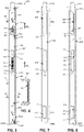
- the latching device 342 comprises a rod 346 nested within a channel 400, as further depicted in the sectional view of FIG. 6 .
- Rod 346 comprises an elongate element extending between a first end 348B and an opposite second end 348A.
- the rod 346 is longitudinally slidably movable relative to, and within, the channel 400 within a fixed range of motion.
- the channel 400 can be mounted to a door or panel, either directly or indirectly via an intermediate member.
- the channel 400 forms part of a door or is incorporated within the door.
- the rod 346 exhibits generally the same behavior as described and illustrated in association with FIGS. 2A-4C , with channel 400 providing a stable platform by which rod 346 may operate to provide selective latching operations. While in some examples rod 346 may have a U-shaped cross-section as shown in FIG. 6 , it will be understood that in some examples, the rod 346 is an elongate element having a rectangular cross-sectional shape (e.g. generally flat). As shown in at least FIG. 6 , in some examples, channel 400 comprises an elongate element having a U-shaped cross section.
- rod 346 comprises a first slot 350, a second slot 370, and a third slot 375.
- First slot 350 is located at second end portion 358 adjacent second end 348A while third slot 375 is located at first end portion 378.
- second slot 370 is located at an intermediate portion of rod 346 between the first and third slots 350, 375. It will be understood that in at least some examples, the intermediate portion need not correspond to a midpoint along a length of rod 346, although it may do so in some example implementations.
- the first slot 350 includes a first end 352 and an opposite second end 354
- the second slot 370 includes a first end 371 and an opposite second end 372
- the third slot 375 includes a first end 376 and an opposite second end 377.
- the labels first, second, and third in relation to at least the slots of rod 346 or of the slots of channel 400 are not limiting or absolute and the labels terms first, second, and third do not reflect a ranking of importance or order. Accordingly, in some examples the labels first, second, and third could be applied differently to the various slots of rod 346 and/or channel 400 without a substantive change in the operation of the rod 346 and/or channel 400.
- an aperture 373 is associated with the second slot 370 and is located adjacent second end 372 of slot 370.
- the aperture 373 is provided to secure an end of a biasing mechanism, being according to the invention an extension spring 392 as will be further described later in association with FIG. 5 . While shown as a triangle, the aperture 373 may be formed in any one of a variety of shapes and/or sizes.
- FIG. 8 is a top plan view of the rod 346 as normally positioned within channel 400 such that the full length of rod 346 is generally superimposed onto a full length of channel 400.
- the channel 400 comprises a first slot 380 which generally has a position, shape, and size generally corresponding to a position, shape, and size of the first slot 350 of rod 346.
- the first slot 380 of channel 400 may sometimes be referred to as being generally coextensive or at least partially coextensive with the first slot 350 of rod 346. It will be understood that part of slot 380 of channel 400 is not visible in FIG. 8 .
- one end 382 of slot 380 of channel 400 comprises a protrusion 384 to receive an end of a biasing mechanism, such as a compression spring 395 as further described and illustrated in association with at least FIG. 5 and FIG. 9 .
- a biasing mechanism such as a compression spring 395
- a forced axial movement of second latch 344A may overcome the biasing force (directional force arrow BF2) associated with second latch 344A (and provided via compression spring 395).
- a variance in spacing between protrusions 34A, 34B such as a shorter distance L4 ( FIGS. 4A-4C ) may provide the forced axial movement with second latch 344A responding by moving closer to the first latch 344B.
- This self-adjustment of the position of second latch 344B facilitates both latches 344A, 344B to firmly engage both of the respective protrusions 34A, 34B as previously described in association with at least FIGS. 4A-4C .
- the relationship of compression spring 395 and second latch 344B, and related components, is further described later in association with at least FIG. 9 .
- the channel 400 comprises a second slot 385 which generally has a position, shape, and size generally corresponding to a position, shape, and size of the second slot 370 of rod 346. Accordingly, in some instances, the second slot 385 of channel 400 may sometimes be referred to as being generally coextensive with the second slot 370 of rod 346. It will be understood that part of slot 385 of channel 400 is not visible in FIG. 8 .
- the channel 400 comprises a aperture 387 to receive an end of a biasing mechanism, such as the extension spring 392 as further described and illustrated in association with at least FIG. 5 and FIG. 9 .
- a biasing mechanism such as the extension spring 392 as further described and illustrated in association with at least FIG. 5 and FIG. 9 .
- extension spring 392 can be secured to channel 400 via aperture 387 and an opposite end 393A of extension spring 392 can be secured to rod 346 via aperture 373, with spring 392 extending within both slot 385 of channel 400 and slot 370 of rod 346. In this orientation, the extension spring 392 extends generally parallel to a length of rod 346 and of channel 400.
- This arrangement couples the rod 346 relative to the channel 400 such that the biasing force BF1 exerted via extension spring 392 maintains a default position (e.g. a first position) of the rod 346 longitudinally relative to the channel 400 until or unless an axial force is applied along rod 346 to overcoming the biasing force BF1 associated with spring 392.
- the extension spring 392 extends between an intermediate portion of the rod 346 and an intermediate portion of the channel 400 to bias the rod 346 in a default first position relative to the channel 400.
- a forced axial movement of rod 346 may overcome the biasing force BF1 associated with rod 346 (and provided via extension spring 392) with the biasing force BF1 causing return of rod 346 to its default, resting position upon removal or cessation of the external force (e.g. F2 in FIG. 3 ) which was driving the selective axial movement of rod 346 relative to channel 400.
- the biasing force BF1 associated with rod 346 and provided via extension spring 392
- the biasing force BF1 causing return of rod 346 to its default, resting position upon removal or cessation of the external force (e.g. F2 in FIG. 3 ) which was driving the selective axial movement of rod 346 relative to channel 400.
- first latch 344B is secured in a fixed location relative to rod 346, but is movable relative to channel 400 upon first latch 344B moving in unison with rod 346 when rod 346 moves relative to channel 400.
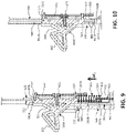
- FIGS. 9 and 10 further illustrate the relationship among the rod 346, the channel 400, the latches 344A, 344B, the springs 392, 395, etc.
- FIG. 9 is a sectional view as taken along lines 9-9 of FIG. 5 , and which illustrates one example implementation of a relationship among at least rod 346, channel 400, second latch 344A, and compression spring 395.
- the slot 350 of rod 346 has a length greater than a length of the base portion 360 of latch 344A such that a portion of slot 350 near spring 395 is not occupied by latch 344A.
- latch 344A includes a base portion 360 having a first end 361A and an opposite second end 361B with a flange 365 extending from the second end 361B to a transverse wall 363.
- One end 397A of spring 395 is secured against wall 363 and bounded by flange 365, while an opposite second end 397B of spring 395 extends onto and is secured relative to protrusion 384 associated with slot 380 of channel 400.
- base portion 360 of latch 344A is slidably movable within slot 350 of bar 346 but is biased into a first position in which flange 361C near first end 361A of latch 344A forcibly, releasably engages end 352 of slot 350 due to the biasing force BF2 exerted via compression spring 395.
- latch 344A Upon application of a sufficient magnitude external force, latch 344A can be moved out of its first position shown in FIG. 9 toward a second position closer to the second end 354 of slot 350. This would introduce a gap between first end 361A of base portion 360 of latch 344A and the first end 352 of slot 350.
- this external force may include forces resulting from latches 344A, 344A (144A, 144A in FIGS. 4A-4C ) attempting to engage protrusions 34A, 34B which have variant spacing such that second latch 344A (144A in FIG. 4B ) is forced toward first latch 344B (144B in FIG. 4B ) to compensate for such variant spacing between protrusions 34A, 34B, as previously described in association with at least FIGS. 4A-4C .
- latch 344A is maintained in its operable slidable position within slot 350 of bar 346 and slot 385 of channel 400 due, at least in part, to backer support 430 secured to base portion 360 of latch 344A via fastener 435. Via backer support 430, latch 344A is retained relative to at least slot 350 while a back-and-forth sliding movement of latch 344A can occur within at least slot 350 (subject to the biasing force BF2 exerted via compression spring 395) within a fixed range of motion.
- FIG. 10 is a sectional view as taken along lines 10-10 of FIG. 5 , according to one example of the present disclosure, and which further illustrates one example implementation of a relationship among at least rod 346, channel 400, and first latch 344B.
- first latch 344B comprises the same shape, size, components, etc. as second latch 344A, except with some of those same components employed in a different way.
- spring 395 is notably absent from FIG.
- transverse wall 393 of base portion 360 of first latch 344B directly contacting end 377 of third slot 375 of bar 346 and flange 365 extending along and contacting portions of bar 346 external to slot 375 to thereby firmly secure the base portion 360 relative to end 377 of slot 375 of bar 346.
- flange 361C near end 361A of base portion 360 of latch 344B is firmly in contact with end 376 of slot 375 of bar 346.
- a backer support 432 like backer support 430 in FIG. 9 , holds latch 344B in its secured location within slot 375 via fastener 435.
- slot 390 of channel 400 is sized and shaped to facilitate the connection of latch 344B and backer support 432 through and relative to slot 375 of bar 346.
- the location of the first latch (44A, 144A, 344A) and the second latch (44B, 144B, 344B) can be switched such that the first latch becomes located adjacent the second end (48A, 148A, 348A) of rod (46, 146, 346) and the second latch becomes located adjacent the first end (48B, 148B, 348B) of the rod.
- an accompanying modification of the rod 346, channel 400, etc. would be made such that the appropriate features and attributes (e.g. slots, springs, etc.) of the rod 346, channel 400, etc. would be available to support the respective latches in their switched locations.
- the location of the protrusions 34A, 34B and the location of the latch device 42, 142, 342 can be switched such that the protrusions become located on the door 40 and the latch device 42, 142, 342 becomes located on the frame 22.
- Appropriate modifications may be made to frame 22 to permit access to various features of the latch device 42, 142, 342.
- the frame 22 can be modified to provide access to a second end 48A, 148A, 348A of the rod to enable pushing down on the rod to disengage the latches of the frame relative to the protrusions of the door.
- a latching device may have more than one self-adjusting latch.
- both the first latch 144B, 344B and the second latch 144A, 344A have a self-adjusting position relative to a length of the rod (46, 146, 346).
- the first latch (44B, 144B, 344B) adjacent the first end of the rod is no longer fixed relative to the rod but instead comprises substantially the same features and attributes as the second latch (44A, 144A, 344A). It will be understood that in such examples the first end portion 378 ( FIG.
- rod 346 and channel 400 would be modified so that slot 375 of rod 346 becomes configured like slot 350 of rod 346, and so that slot 390 of channel 400 becomes configured like slot 380 of channel 400.
- a second compression spring like spring 395 would be incorporated into the modified slots of the rod and channel, which receive the self-adjusting fist latch 44A, 144A, 344A.
- one or both of the self-adjusting latches of a latching device may compensate for variations in spacing between protrusions 34A, 34B, for variations in the default spacing between latches, and/or for variations in the size and/or shape of the protrusions 34A, 34B and respective latches.
- a latching device comprises two self-adjusting latches like second latch (e.g. 144A in FIGS. 2A-4C ; 344A in FIGS. 5 , 9-10 )
- the latching device comprises a rod (e.g. 146 in FIGS. 2A-4C ; 346 in FIGS. 5-10 ) slidably movable between a first position and a second position, with the rod 146, 346 including a first end and an opposite second end with the rod 146, 346 biased into the first position.
- the latching device is to releasably engage a pair of protrusions spaced apart by a first distance.
- a first latch like self-adjusting latch 144A, 344A is slidably movable adjacent the first end 148B, 348B of the rod 146, 346 between a first position and a second position with the first latch biased into the first position.
- a second latch like self-adjusting latch 144A, 344A is slidably movable adjacent the second end 148A, 348A of the rod 146, 346 between a first position and a second position closer to the first latch, with the second latch biased into the first position. In the second position, the first latch is closer to the second latch.
- each respective first and second latch (each being like latch 144A, 344A) is in the first position, the first and second latches are spaced apart by a second distance.
- both the first and second latches Upon slidable movement of the rod 146, 346 both the first and second latches generally move in unison to permit a releasable engagement of the first and second latches relative to the protrusions to releasably secure the door relative to the frame, including selective movement of at least one of the first and second latches toward the second position (of each respective first and second latch) upon the first distance being less than the second distance.
- a latching device may have a single latch with the single latch comprising at least substantially the same features and attributes as a self-adjusting latch (e.g. 144A, 344A). Stated differently, in such a latching device just one latch would be present and it would not have a fixed position (e.g. non-movable position) relative to the rod of the latching device. In some examples, a single self-adjusting latch may suffice for a smaller sized door.
Landscapes
- Engineering & Computer Science (AREA)
- Mechanical Engineering (AREA)
- Structural Engineering (AREA)
- Lock And Its Accessories (AREA)
- Closing And Opening Devices For Wings, And Checks For Wings (AREA)
Description
- Most imaging devices include a panel or door to provide access for maintenance or replacing consumables, such as paper, ink, etc.
US 2010/0117384 A1 relates to a gaming machine door latch.DE 10 2011 050226 A1 relates to a device with non movable latches relative to a rod. -
-
FIG. 1A is a perspective view schematically representing a container including a latching device, according to one example of the present disclosure. -
FIG. 1B is a block diagram schematically representing an imaging device, according to one example of the present disclosure. -
FIGS. 2A-2C are a series of diagrams, each including a side view schematically representing a latching device in a particular position and relationship relative to a pair of protrusions, according to one example of the present disclosure. -
FIG. 3 is a diagram including a side view schematically representing a latching device relative to a pair of protrusions, according to one example of the present disclosure. -
FIGS. 4A-4C are a series of diagrams, each including a side view schematically representing a latching device in a particular position and relationship relative to a pair of protrusions, according to one example of the present disclosure. -
FIG. 5 is a top plan view schematically representing a latching device, according to one example of the present disclosure. -
FIG. 6 is a sectional view as taken along lines 6-6 ofFIG. 5 , according to one example of the present disclosure. -
FIG. 7 is a top plan view of a rod of a latching device, according to one example of the present disclosure. -
FIG. 8 is a top plan view of a rod and a channel of a latching device, according to one example of the present disclosure. -
FIG. 9 is a sectional view as taken along lines 9-9 ofFIG. 5 , according to one example of the present disclosure. -
FIG. 10 is a sectional view as taken along lines 10-10 ofFIG. 5 , according to one example of the present disclosure. - The invention is defined by the appended claims. At least some examples of the present disclosure are directed to a latching device to releasably secure a door relative to a frame. In some examples, the latching device includes a pair of spaced apart latches with at least one of the latches being self-adjusting in its position relative to a rod which supports the pair of latches. The at least one self-adjusting latch may compensate for manufacturing variances in spacing, sizes, or shapes of a pair of protrusions on the frame and to which the latches are releasably engageable. The at least one self-adjusting latch also may compensate for manufacturing variances in spacing, sizes, or shapes of the latches, including the at least one self-adjusting latch.
- Via at least some such example arrangements, both latches of a latching device become firmly engageable relative to a pair of protrusions on a frame, thereby reducing vibration and/or reducing the chance of the door opening unexpectedly which might otherwise occur if the door were loose.
- These examples, and additional examples, are described in association with at least
FIGS. 1-10 . -
FIG. 1 is a perspective view schematically representing acontainer 20 including alatching device 42, according to one example of the present disclosure. As shown inFIG. 1 ,container 20 includes aframe 22, which may define a cavity or aperture.Frame 22 includes a pair of spaced apartprotrusions door 40 is pivotally mounted toframe 22 and comprises thelatching device 42. In some examples,latching device 42 comprises a pair of spaced apartlatches protrusions frame 22 in order to selectively close and securedoor 40 relative toframe 22. - In some examples, each
protrusion latches protrusions - In some examples, the
container 20 may comprise and/or may contain animaging device 60, such as but not limited to an image formation device (e.g. scanner, printer, copier) or an ancillary support for an image formation device. -
FIGS. 2A-2C are a series of side views schematically representing alatching device 142 in various positions relative to a pair ofprotrusions latching device 142 comprises at least some of substantially the same features and attributes of latching device 42 (FIG. 1 ). In some examples,latching device 142 comprises one example implementation of thelatching device 42 inFIG. 1 with similar reference numerals denoting similar elements. However, in some examples,latching device 142 can be implemented in association with containers or structures having shapes, sizes, etc. other than that shown inFIG. 1 and/or for purposes other than imaging-related functions (FIG. 2 ). - As shown in the side view of the diagram 100 of
FIG. 2A ,latching device 142 comprises arod 146, such as an elongate element extending between afirst end 148B and an oppositesecond end 148A. The elongate element may be rigid or at least sufficiently resilient so as to not buckle upon the application of forces generally associated with latching. As further shown inFIG. 2A , thelatching device 142 comprises a pair of latches, including afirst latch 144B and asecond latch 144A. In some examples, eachlatch ramp portion 162 and arecess portion 164, both supported by abase portion 160. - According to the invention, the
first latch 144B is secured relative to therod 146 in a fixed location adjacent thefirst end 148B ofrod 146. As shown inFIG. 2A , in some examples thefirst latch 144B is oriented with the mouth ofrecess portion 164 facing toward thesecond latch 144A. In some examples, thesecond latch 144A is spaced apart from thefirst latch 144B by a second distance L2. In some examples, this distance is measured from therecess portion 164 of onelatch 144B to therecess portion 164 of theother latch 144A. As further described later in association with at leastFIGS. 4A-4C andFIGS. 5-10 , in some examples thesecond latch 144A is movable relative to the length ofrod 146. - In some examples, diagram 100 includes a pair of
protrusions FIG. 1 ), which represent protrusions like those onframe 22 inFIG. 1 . In some examples, theprotrusions latches latches protrusions - As further shown in
FIG. 2A , with reference to therecess portion 164, thesecond latch 144A is spaced apart from thesecond end 148A of therod 146 by a third distance L3. In one aspect, this position of thesecond latch 144A may sometimes be referred to as a first position of thesecond latch 144A to the extent that in at least some instances thesecond latch 144A is slidably movable relative to therod 146, such as later described in association with at leastFIGS. 4A-4C . -
FIG. 2B is a side view likeFIG. 2A , except showing thelatching device 146 in a transition stage during active engagement oflatching device 142 relative toprotrusions FIG. 2B , aslatch 142 is pressed towardprotrusions ramp portions 162 of eachlatch respective protrusions rod 146 to slide in a first direction (e.g. downward in some examples) as represented via directional arrows D. Bothfirst latch 144A and second 144B generally move in unison withrod 146 in the first direction. While some details are not shown inFIG. 2B for illustrative simplicity,rod 146 is biased (as represented by directional force arrow BF1) into a first position shown inFIG. 2A and given a sufficient force, such as caused viaramp portions 162 oflatches protrusions rod 146 to slide in the first direction as shown inFIG. 2B . - In addition to the pressing force F1,
FIG. 2B also depicts a directional arrow I for eachrespective latch protrusions - This movement of rod 146 (and latches 144A, 144B) continues in the first direction (D) and laterally (I) until the
latches respective protrusions recess portion 164 of thelatches FIG. 2C , the final seating motion occurs via the rod 146 (and latches 144A, 144B) sliding upward (as represented via directional arrows U) as the biasing force (BF1) onrod 146 causes therod 146 to return toward its first position (FIG. 2A ). In this way, therecess portion 164 of the respective latches become firmly engaged against therespective protrusions FIG. 2C to thereby releasably secure therod 146 and latches 144A, 144B relative to theprotrusions door 40 becoming releasably secured relative to the frame on which protrusions 34A, 34B offrame 22 are formed or mounted. - As shown in
FIG. 3 , when it is desired to release thedoor 40 from theframe 22, an external force (as represented by directional force arrow F2) is applied againstsecond end 148A ofrod 146 to causerod 146 to overcome its biasing force BF1 to move in the first direction (arrows D) and laterally away fromprotrusions latches FIG. 3 . Once thelatches protrusions door 40 away from theframe 22. - It will be understood that the series of diagrams in
FIGS. 2A-3 represents an ideal situation in which the first distance L1 (e.g. a default distance) between theprotrusions latches respective protrusions FIG. 2C . However, as described below, the diagrams inFIGS. 4A-4C represent a situation in which there is at least a slight mismatch of the distance betweenprotrusions latches second latch 144A. -
FIGS. 4A-4C are a series of side views schematically representing a latching device in various positions relative to a pair of protrusions, according to one example of the present disclosure. Thelatching device 142 depicted inFIGS. 4A-4C comprises the same features and attributes as thelatching device 142 inFIGS. 2A-3 . However, as shown inFIG. 4A , the distance L4 between theprotrusions e.g. latch 144B) may not firmly engage the protrusions in the absence of a correcting factor such as self-adjustinglatch 144A. In some instances, this behavior may sometimes be exhibited when the first distance (L4) betweenprotrusions latches - With this in mind, as shown in
FIG. 4B , upon a desired engagement of the latching device 142 (and therefore a door or other object to whichlatching device 142 is mounted) relative to protrusions 34A, 34B the same process as previously described inFIG. 2B is followed. However, in this instance the shorter distance L4 (between protrusions 34A, 34B) may induce a pressing action byprotrusion 34A onsecond latch 144A sufficient to overcome a biasing force (as represented via directional force arrow BF2) acting onlatch 144A, thereby permittingsecond latch 144A to slidably move in the first direction relative torod 146, as represented via directional arrow M. This movement is in addition to the general movement oflatch 144A in unison withrod 146 as represented via directional arrows D. The independent movement oflatch 144A relative torod 146 is just enough to accommodate the variance in the distance L4 (FIGS. 4A-4C ) from the default distance L1 (FIG. 2A-3 ) with the biasing force BF2 preventing further movement ofsecond latch 144A towardfirst latch 144B. - In one aspect, the movement of
second latch 144A from its first default position (e.g. its biased first position) into a second position closer to thefirst latch 144A enables thefirst latch 144B to engage itsrespective protrusion 34B with sufficient force (due to BF1) to be firmly engaged relative toprotrusion 34B, while thesecond latch 144B maintains engagement relative to itsrespective protrusion 34A. It will be understood that in at least some examples, the second position to whichsecond latch 144A (independent of rod 346) moves closer to thesecond latch 144A is not a static location but generally refers to any point other than the first default position ofsecond latch 144A within its range of motion at least partially defined by a slot (e.g. 350 inFIGS. 5-10 ) inrod 346 near a second end portion (e.g. 358 inFIG. 7 ). - Upon this self-adjustment of
latch 144A and as shown inFIG. 4C , thesecond latch 144A becomes spaced apart fromfirst latch 144B by a distance L5, which is less than the default distance L2 (FIG. 2A-3 , andFIG. 4A ). In other words, thesecond latch 144A moved toward the fixedfirst latch 144B to compensate for the variance in spacing (e.g. reduction in this instance) between theprotrusions second latch 144A is also evidenced via the distance L6 between thelatch 144A (with reference to recess portion 164) and thesecond end 148A of therod 146, with distance L6 being greater than the default distance L3 (FIG. 2A ) between thesecond latch 144A and thesecond end 148A of therod 146. - It will be understood that other variations in manufacturing may result in a varied distance between
protrusions protrusions latches respective latches latch 144A may accommodate such variances to help ensure that both latches 144A, 144B firmly engage theprotrusions - With further reference to at least
FIG. 4B , while not a functional aspect of operation of thesecond latch 144A during opening and/or closing a door, thesecond latch 144A can move relative to therod 346 even whenrod 346 is not moved (and therefore even whenfirst latch 144B is not moved). Accordingly, this arrangement demonstrates that movement ofsecond latch 144A is independent of thefirst latch 144B (and of the rod 346) in at least some circumstances. -
FIG. 5 is a top plan view schematically representing alatching device 342, according to one example of the present disclosure. In some examples, thelatching device 342 comprises at least some of substantially the same features and attributes as the latchingdevice FIGS. 1-4C . In some examples, thelatching device 342 may comprise one example implementation of at least one of thelatching devices FIGS. 1-4C . With this in mind, similar reference elements in different Figures may refer to similar elements. -
FIG. 5 depicts thelatching device 342 in an assembled state, whileFIGS. 7 and 8 depict at least some components of latchingdevice 342 in isolation to aid understanding of the relationship among the various components. - As shown in
FIG. 5 , in some examples, thelatching device 342 comprises arod 346 nested within achannel 400, as further depicted in the sectional view ofFIG. 6 .Rod 346 comprises an elongate element extending between afirst end 348B and an oppositesecond end 348A. Therod 346 is longitudinally slidably movable relative to, and within, thechannel 400 within a fixed range of motion. Meanwhile, thechannel 400 can be mounted to a door or panel, either directly or indirectly via an intermediate member. In some examples, thechannel 400 forms part of a door or is incorporated within the door. - The
rod 346 exhibits generally the same behavior as described and illustrated in association withFIGS. 2A-4C , withchannel 400 providing a stable platform by whichrod 346 may operate to provide selective latching operations. While in someexamples rod 346 may have a U-shaped cross-section as shown inFIG. 6 , it will be understood that in some examples, therod 346 is an elongate element having a rectangular cross-sectional shape (e.g. generally flat). As shown in at leastFIG. 6 , in some examples,channel 400 comprises an elongate element having a U-shaped cross section. - As further shown in
FIG. 7 , in someexamples rod 346 comprises afirst slot 350, asecond slot 370, and athird slot 375.First slot 350 is located atsecond end portion 358 adjacentsecond end 348A whilethird slot 375 is located atfirst end portion 378. Meanwhile, in some examplessecond slot 370 is located at an intermediate portion ofrod 346 between the first andthird slots rod 346, although it may do so in some example implementations. In some examples, thefirst slot 350 includes afirst end 352 and an oppositesecond end 354, thesecond slot 370 includes afirst end 371 and an oppositesecond end 372, and thethird slot 375 includes afirst end 376 and an oppositesecond end 377. - It will be understood that the labels first, second, and third in relation to at least the slots of
rod 346 or of the slots ofchannel 400 are not limiting or absolute and the labels terms first, second, and third do not reflect a ranking of importance or order. Accordingly, in some examples the labels first, second, and third could be applied differently to the various slots ofrod 346 and/orchannel 400 without a substantive change in the operation of therod 346 and/orchannel 400. - In some examples, an
aperture 373 is associated with thesecond slot 370 and is located adjacentsecond end 372 ofslot 370. Theaperture 373 is provided to secure an end of a biasing mechanism, being according to the invention anextension spring 392 as will be further described later in association withFIG. 5 . While shown as a triangle, theaperture 373 may be formed in any one of a variety of shapes and/or sizes. -
FIG. 8 is a top plan view of therod 346 as normally positioned withinchannel 400 such that the full length ofrod 346 is generally superimposed onto a full length ofchannel 400. As shown inFIG. 8 , in some examples, thechannel 400 comprises afirst slot 380 which generally has a position, shape, and size generally corresponding to a position, shape, and size of thefirst slot 350 ofrod 346. In some instances, thefirst slot 380 ofchannel 400 may sometimes be referred to as being generally coextensive or at least partially coextensive with thefirst slot 350 ofrod 346. It will be understood that part ofslot 380 ofchannel 400 is not visible inFIG. 8 . - In addition, one
end 382 ofslot 380 ofchannel 400 comprises aprotrusion 384 to receive an end of a biasing mechanism, such as acompression spring 395 as further described and illustrated in association with at leastFIG. 5 andFIG. 9 . With this in mind, it will be understood that bothslot 350 ofrod 346 and slot 380 ofchannel 400 are sized and shaped to receive atleast compression spring 395 in association withlatch 344A. - As previously described in association with at least
FIGS. 4A-4C , a forced axial movement ofsecond latch 344A may overcome the biasing force (directional force arrow BF2) associated withsecond latch 344A (and provided via compression spring 395). In particular, in some instances a variance in spacing between protrusions 34A, 34B, such as a shorter distance L4 (FIGS. 4A-4C ) may provide the forced axial movement withsecond latch 344A responding by moving closer to thefirst latch 344B. This self-adjustment of the position ofsecond latch 344B facilitates bothlatches respective protrusions FIGS. 4A-4C . The relationship ofcompression spring 395 andsecond latch 344B, and related components, is further described later in association with at leastFIG. 9 . - As further shown in
FIG. 8 , in some examples, thechannel 400 comprises asecond slot 385 which generally has a position, shape, and size generally corresponding to a position, shape, and size of thesecond slot 370 ofrod 346. Accordingly, in some instances, thesecond slot 385 ofchannel 400 may sometimes be referred to as being generally coextensive with thesecond slot 370 ofrod 346. It will be understood that part ofslot 385 ofchannel 400 is not visible inFIG. 8 . - In addition,
adjacent end 386 ofslot 385 thechannel 400 comprises aaperture 387 to receive an end of a biasing mechanism, such as theextension spring 392 as further described and illustrated in association with at leastFIG. 5 andFIG. 9 . With this in mind, it will be understood that bothslot 370 ofrod 346 and slot 385 ofchannel 400 are sized and shaped to receivespring 392. - From
FIG. 8 , it can be further seen with regard to therespective slots aperture 387adjacent end 386 ofslot 385 ofchannel 400 is opposite to, and generally faces, theaperture 373adjacent end 372 ofslot 370 ofrod 346. With this arrangement, and as shown viaFIGS. 5 and 8 , oneend 393B ofextension spring 392 can be secured to channel 400 viaaperture 387 and anopposite end 393A ofextension spring 392 can be secured torod 346 viaaperture 373, withspring 392 extending within bothslot 385 ofchannel 400 and slot 370 ofrod 346. In this orientation, theextension spring 392 extends generally parallel to a length ofrod 346 and ofchannel 400. This arrangement couples therod 346 relative to thechannel 400 such that the biasing force BF1 exerted viaextension spring 392 maintains a default position (e.g. a first position) of therod 346 longitudinally relative to thechannel 400 until or unless an axial force is applied alongrod 346 to overcoming the biasing force BF1 associated withspring 392. In some examples, with this arrangement theextension spring 392 extends between an intermediate portion of therod 346 and an intermediate portion of thechannel 400 to bias therod 346 in a default first position relative to thechannel 400. - For instance, as previously described in association with at least
FIGS. 2B-3 andFIG. 4B , a forced axial movement ofrod 346 may overcome the biasing force BF1 associated with rod 346 (and provided via extension spring 392) with the biasing force BF1 causing return ofrod 346 to its default, resting position upon removal or cessation of the external force (e.g. F2 inFIG. 3 ) which was driving the selective axial movement ofrod 346 relative to channel 400. - As further shown in
FIG. 5 ,first latch 344B is secured in a fixed location relative torod 346, but is movable relative to channel 400 uponfirst latch 344B moving in unison withrod 346 whenrod 346 moves relative tochannel 400. - Given this context, the sectional views of
FIGS. 9 and 10 further illustrate the relationship among therod 346, thechannel 400, thelatches springs - In particular,
FIG. 9 is a sectional view as taken along lines 9-9 ofFIG. 5 , and which illustrates one example implementation of a relationship among atleast rod 346,channel 400,second latch 344A, andcompression spring 395. - As shown in
FIG. 9 , theslot 350 ofrod 346 has a length greater than a length of thebase portion 360 oflatch 344A such that a portion ofslot 350 nearspring 395 is not occupied bylatch 344A. - As further shown in
FIG. 9 , in some examples latch 344A includes abase portion 360 having afirst end 361A and an oppositesecond end 361B with aflange 365 extending from thesecond end 361B to atransverse wall 363. Oneend 397A ofspring 395 is secured againstwall 363 and bounded byflange 365, while an oppositesecond end 397B ofspring 395 extends onto and is secured relative toprotrusion 384 associated withslot 380 ofchannel 400. Accordingly,base portion 360 oflatch 344A is slidably movable withinslot 350 ofbar 346 but is biased into a first position in which flange 361C nearfirst end 361A oflatch 344A forcibly, releasably engages end 352 ofslot 350 due to the biasing force BF2 exerted viacompression spring 395. - Upon application of a sufficient magnitude external force, latch 344A can be moved out of its first position shown in
FIG. 9 toward a second position closer to thesecond end 354 ofslot 350. This would introduce a gap betweenfirst end 361A ofbase portion 360 oflatch 344A and thefirst end 352 ofslot 350. In some examples, this external force may include forces resulting fromlatches FIGS. 4A-4C ) attempting to engageprotrusions second latch 344A (144A inFIG. 4B ) is forced towardfirst latch 344B (144B inFIG. 4B ) to compensate for such variant spacing between protrusions 34A, 34B, as previously described in association with at leastFIGS. 4A-4C . - As further shown in
FIG. 9 ,latch 344A is maintained in its operable slidable position withinslot 350 ofbar 346 and slot 385 ofchannel 400 due, at least in part, tobacker support 430 secured tobase portion 360 oflatch 344A viafastener 435. Viabacker support 430,latch 344A is retained relative to atleast slot 350 while a back-and-forth sliding movement oflatch 344A can occur within at least slot 350 (subject to the biasing force BF2 exerted via compression spring 395) within a fixed range of motion. -
FIG. 10 is a sectional view as taken along lines 10-10 ofFIG. 5 , according to one example of the present disclosure, and which further illustrates one example implementation of a relationship among atleast rod 346,channel 400, andfirst latch 344B. In some examples,first latch 344B comprises the same shape, size, components, etc. assecond latch 344A, except with some of those same components employed in a different way. For instance,spring 395 is notably absent fromFIG. 10 , with the transverse wall 393 ofbase portion 360 offirst latch 344B directly contactingend 377 ofthird slot 375 ofbar 346 andflange 365 extending along and contacting portions ofbar 346 external to slot 375 to thereby firmly secure thebase portion 360 relative to end 377 ofslot 375 ofbar 346. - Meanwhile, as in
FIG. 10 ,flange 361C nearend 361A ofbase portion 360 oflatch 344B is firmly in contact withend 376 ofslot 375 ofbar 346. Abacker support 432, likebacker support 430 inFIG. 9 , holdslatch 344B in its secured location withinslot 375 viafastener 435. Meanwhile slot 390 ofchannel 400 is sized and shaped to facilitate the connection oflatch 344B andbacker support 432 through and relative to slot 375 ofbar 346. - In some examples, the location of the first latch (44A, 144A, 344A) and the second latch (44B, 144B, 344B) can be switched such that the first latch becomes located adjacent the second end (48A, 148A, 348A) of rod (46, 146, 346) and the second latch becomes located adjacent the first end (48B, 148B, 348B) of the rod. It will be understood that an accompanying modification of the
rod 346,channel 400, etc. would be made such that the appropriate features and attributes (e.g. slots, springs, etc.) of therod 346,channel 400, etc. would be available to support the respective latches in their switched locations. - In some examples, the location of the
protrusions latch device door 40 and thelatch device frame 22. Appropriate modifications may be made to frame 22 to permit access to various features of thelatch device frame 22 can be modified to provide access to asecond end - In some examples, a latching device (e.g. 42, 142, 342) may have more than one self-adjusting latch. Stated differently, in some examples both the
first latch second latch FIG. 7-8 ) ofrod 346 andchannel 400 would be modified so thatslot 375 ofrod 346 becomes configured likeslot 350 ofrod 346, and so thatslot 390 ofchannel 400 becomes configured likeslot 380 ofchannel 400. As a related matter, a second compression spring likespring 395 would be incorporated into the modified slots of the rod and channel, which receive the self-adjustingfist latch - With this arrangement, one or both of the self-adjusting latches of a latching device may compensate for variations in spacing between protrusions 34A, 34B, for variations in the default spacing between latches, and/or for variations in the size and/or shape of the
protrusions - In one example implementation in which a latching device comprises two self-adjusting latches like second latch (e.g. 144A in
FIGS. 2A-4C ; 344A inFIGS. 5 ,9-10 ), the latching device comprises a rod (e.g. 146 inFIGS. 2A-4C ; 346 inFIGS. 5-10 ) slidably movable between a first position and a second position, with therod rod latch first end rod latch second end rod latch rod - Instead of having two latches such as the
first latch second latch
Claims (15)
- A device (100, 200, 300) comprising:a rod (146 ,346) slidably movable relative to a fixed channel (400) between a first position and a second position, the rod biased into the first position;a first latch (144B, 344B) secured relative to the rod in a fixed location adjacent a first end portion of the rod; and characterized bya second latch (144A, 344A) slidably movable within a first slot (350) of the second end portion of the rod between a first position and a second position closer to the first latch, the second latch biased into the first position, andupon slidable movement of the rod, both the first and second latches generally move in unison to permit a releasable engagement of the first and second latches relative to two spaced apart protrusions (34A, 34B) of a frame (22) to releasably secure a door (40) relative to the frame.
- The device (100, 200, 300) of claim 1, wherein the protrusions (34A, 34B) of the frame (22) are spaced apart by a first distance and in the event that the first distance is less than a default second distance between the first latch (144B, 344B) and the second latch (144A, 344A), the second latch to move into the second position upon both the first and second latches engaging the respective protrusions.
- The device (100, 200, 300) of claim 1, comprising:
an extension spring (392) longitudinally parallel to the rod (146 ,346), and extending between an intermediate portion of the rod and an intermediate portion of the channel (400) to bias the rod in the first position relative to the channel. - The device (100, 200, 300) of claim 3, wherein the extension spring (392) is located within and coextensive with a second slot in the intermediate portion of the rod (146 ,346) and with a first slot (380) in the intermediate portion of the channel (400).
- The device (100, 200, 300) of claim 1, a compression spring (395) longitudinally parallel to the rod (146 ,346), and extending between the second latch (144A, 344A) and a protrusion (34A, 34B) of the channel (400) to bias the second latch into the first position relative to the rod.
- The device (100, 200, 300) of claim 5, wherein the channel (400) comprises a second slot including one end comprising the protrusion (34A, 34B), and wherein the compression spring (395) is located within and coextensive with at least a portion of the second slot of the channel and with at least a portion of a second slot of the rod (146, 346) adjacent a first end portion of the respective rod and channel.
- The device (100, 200, 300) of claim 1, wherein the respective first and second latches (144B, 344B, 144A, 344A) each comprise:a ramp portion (162) to slidably engage a respective one of the protrusions (34A, 34B); anda recess portion (164) to releasably engage the respective protrusion, after slidable engagement between the ramp portion and the respective protrusion, to retain the door (40) in secured position relative to frame (22).
- A device (100, 200, 300) comprising:a frame (22) including a first side including a first protrusion and a second protrusion (34A, 34B) spaced apart from the first protrusion by a first distance;a door (40) pivotally mounted relative to the frame and including a latching device, which comprises:
a channel (400) mounted to the door; andthe device of claim 1 wherein the rod (146 ,346) is slidably movable relative to the channel mounted to the door. - The device (100, 200, 300) of claim 8, wherein in the event that the first distance is less than a default second distance between the first latch (144B, 344B) and the second latch (144A, 344A), the second latch to move into the second position upon both the first and second latches engaging the respective protrusions (34A, 34B).
- The device (100, 200, 300) of claim 8, comprising:an extension spring (392) longitudinally parallel to the rod (146 ,346), and extending between an intermediate portion of the rod and an intermediate portion of the channel (400) to bias the rod in the first position relative to the channel; anda compression spring (395) longitudinally parallel to the rod, and extending between the second latch (144A, 344A) and a protrusion of the channel to bias the second latch in the first position relative to the rod.
- The device (100, 200, 300) of claim 8, wherein the respective first and second latches (144B, 344B, 144A, 344A) each comprise:a ramp portion (162) to slidably engage a respective one of the protrusions (34A, 34B); anda recess portion (164) to releasably engage the respective protrusion, after slidable engagement between the ramp portion and the respective protrusion, to retain the door (40) in secured position relative to frame (22).
- The device of claim 8, comprising an imaging-related device (60) at least partially housed within the frame (22).
- A latching device (100, 200, 300) comprising:a channel (400) fixed to a door (40);a rod (146 ,346) slidably movable relative to the channel between a first position and a second position;a first latch (144B, 344B) slidably movable adjacent a first end of the rod between a first position and a second position with the first latch biased into the first position; anda second latch (144A, 344A) slidably movable adjacent a second end of the rod between a first position and a second position closer to the first latch,the second latch biased into the first position,wherein when each respective first and second latch is in the first position, the first and second latches are spaced apart by a second distance, andupon slidable movement of the rod, both the first and second latches generally move in unison to permit a releasable engagement of the first and second latches relative to two spaced apart protrusions (34A, 34B) of a frame (22) to releasably secure the door relative to the frame, characterized in that the latching device comprises:
an extension spring (392) to exert a biasing force to maintain a default position of the rod (146, 346) relative to the channel (400). - The device (100, 200, 300) of claim 13, in which at least one of the first and second latches (144A, 344A, 144B, 344B) move toward the second position upon a first distance being less than the second distance.
- The device (100, 200, 300) of claim 13, comprising:a first compression spring longitudinally parallel to the rod (146 ,346), and extending between the first latch (144B, 344B) and a first protrusion of the channel (400) to bias the first latch in the first position relative to the rod; anda second compression spring longitudinally parallel to the rod and extending between the second latch (144A, 344A) and a second protrusion of the channel to bias the second latch in the first position relative to the rod.
Applications Claiming Priority (1)
| Application Number | Priority Date | Filing Date | Title |
|---|---|---|---|
| PCT/US2016/051306 WO2018048442A1 (en) | 2016-09-12 | 2016-09-12 | Releasable latch |
Publications (3)
| Publication Number | Publication Date |
|---|---|
| EP3510219A1 EP3510219A1 (en) | 2019-07-17 |
| EP3510219A4 EP3510219A4 (en) | 2020-05-20 |
| EP3510219B1 true EP3510219B1 (en) | 2022-10-26 |
Family
ID=61561493
Family Applications (1)
| Application Number | Title | Priority Date | Filing Date |
|---|---|---|---|
| EP16915894.6A Active EP3510219B1 (en) | 2016-09-12 | 2016-09-12 | Releasable latch |
Country Status (3)
| Country | Link |
|---|---|
| US (1) | US11408212B2 (en) |
| EP (1) | EP3510219B1 (en) |
| WO (1) | WO2018048442A1 (en) |
Families Citing this family (2)
| Publication number | Priority date | Publication date | Assignee | Title |
|---|---|---|---|---|
| IT201900015524A1 (en) * | 2019-09-03 | 2021-03-03 | Benedetto Fedeli | DOOR LOCK |
| US11873669B2 (en) * | 2021-01-15 | 2024-01-16 | The Boeing Company | Single release latching system with multiple independently latching latch assemblies |
Family Cites Families (39)
| Publication number | Priority date | Publication date | Assignee | Title |
|---|---|---|---|---|
| US695313A (en) | 1901-10-19 | 1902-03-11 | John Kroder & Henry Reubel Co | Curtain-pole ring. |
| FR409754A (en) * | 1909-11-27 | 1910-04-30 | Georges Louis Canard | Iron and icing |
| US1677278A (en) * | 1927-08-01 | 1928-07-17 | Berger Mfg Co | Locker latch |
| US1809804A (en) * | 1930-02-07 | 1931-06-09 | Nathan Schoenthal | Latch operating means for directory boards, etc. |
| US3462980A (en) * | 1968-02-12 | 1969-08-26 | Equito Electronics Corp | Latching device for cabinets |
| SE440383B (en) * | 1978-12-11 | 1985-07-29 | Sharp Kk | DORRLAS device for a cooking stove, in particular a microwave oven |
| FR2486577A1 (en) * | 1980-07-11 | 1982-01-15 | Ferco Int Usine Ferrures | LOCKING FERRULE OF A WINDOW SLIDING DOOR, DOOR OR THE LIKE |
| ES267023Y (en) * | 1982-08-31 | 1983-09-16 | SECURITY CLOSING DEVICE FOR CURRENCY-OPERATED MACHINES. | |
| FR2571086B1 (en) * | 1984-10-01 | 1989-09-29 | Ferco Int Usine Ferrures | LOCKING FIXTURE, PARTICULARLY FOR SLIDING OPENING. |
| GB8431035D0 (en) * | 1984-12-07 | 1985-01-16 | Smith M L | Latch mechanisms |
| US4643005A (en) * | 1985-02-08 | 1987-02-17 | Adams Rite Manufacturing Co. | Multiple-bolt locking mechanism for sliding doors |
| KR870001626Y1 (en) * | 1985-05-24 | 1987-04-30 | 주식회사금성사 | Locking device for door of electronic range |
| US4875721A (en) * | 1988-11-10 | 1989-10-24 | Imanishi Kinzoku Kogyo Kabushiki Kaisha | Latch assembly for door or window of microwave range |
| KR920007325Y1 (en) * | 1989-09-12 | 1992-10-12 | 삼성전자 주식회사 | Locking lever for fax |
| FR2681632B1 (en) * | 1991-09-20 | 1993-11-19 | Cga Hbs Cie Gle Automatisme | ANTI-BREAKAGE CLOSING SYSTEM FOR A METAL CABINET DOOR. |
| FR2701056B1 (en) * | 1993-02-01 | 1995-04-07 | Stremler | Lock hook adjustment device, in particular for sliding frame. |
| JP3599275B2 (en) * | 1993-07-21 | 2004-12-08 | シャープ株式会社 | microwave |
| US5524944A (en) * | 1994-08-05 | 1996-06-11 | Debourgh Manufacturing Company | Latch |
| US5642909A (en) * | 1996-03-01 | 1997-07-01 | Federal-Hoffman, Inc. | Latch system |
| IT1293287B1 (en) * | 1997-08-04 | 1999-02-16 | Erreti Srl | CLOSING DEVICE FOR SLIDING DOORS. |
| FR2777588B1 (en) * | 1998-04-17 | 2001-03-23 | Ferco Int Usine Ferrures | LOCKING DEVICE FOR SLIDING DOOR |
| JP4215346B2 (en) | 1999-06-30 | 2009-01-28 | 三洋電機株式会社 | Organic matter processing equipment |
| KR100354068B1 (en) | 1999-11-29 | 2002-09-26 | 삼성전자 주식회사 | Front door of a liquid electrophotographic printer |
| GB0016854D0 (en) | 2000-07-11 | 2000-08-30 | Apw Electronics Ltd | Door latching mechanism |
| US7370890B2 (en) * | 2000-11-07 | 2008-05-13 | Delta Consolidated Industries | Storage cabinet with locking system having dual release members |
| US7168745B2 (en) * | 2004-09-28 | 2007-01-30 | Mohammad Ali Jamnia | Device for latching a cabinet door |
| JP4534820B2 (en) | 2005-03-17 | 2010-09-01 | 船井電機株式会社 | Printer paper tray |
| CY2545B1 (en) * | 2005-09-27 | 2008-07-02 | A C Technometal Ltd | |
| CN2862145Y (en) * | 2005-11-14 | 2007-01-24 | 鸿富锦精密工业(深圳)有限公司 | Buckle device |
| US7815228B2 (en) * | 2007-11-02 | 2010-10-19 | Dell Products L.P. | Apparatus, systems and methods for damping vibration of an elastic member within an information handling system latch |
| US8191936B2 (en) * | 2008-11-12 | 2012-06-05 | Cole Kepro International, Llc | Gaming machine door latch |
| US8167386B2 (en) * | 2009-03-26 | 2012-05-01 | American Power Conversion Corporation | Door assembly and method of replacing a door of an electronics cabinet |
| EP2322382A1 (en) | 2009-11-16 | 2011-05-18 | Zadi S.p.A. | Locking system for cases and vehicle roof boxes |
| FR2959770B1 (en) | 2010-05-10 | 2020-03-06 | Grosfillex Sas | LOCKING CONTROL DEVICE FOR LEAF |
| JP2015118367A (en) | 2013-11-14 | 2015-06-25 | キヤノン株式会社 | Image forming apparatus |
| US9280087B2 (en) | 2013-11-20 | 2016-03-08 | Lexmark International, Inc. | Electrophotographic image forming device latching system for retaining a replaceable unit |
| JP6043740B2 (en) | 2014-02-17 | 2016-12-14 | 京セラドキュメントソリューションズ株式会社 | Image forming apparatus |
| JP6225860B2 (en) | 2014-09-22 | 2017-11-08 | 京セラドキュメントソリューションズ株式会社 | Cover opening / closing device and image forming apparatus having the same |
| FR3102496B1 (en) * | 2019-10-29 | 2021-11-12 | La Croisee D S | Locking device for a sliding door |
-
2016
- 2016-09-12 US US16/332,074 patent/US11408212B2/en active Active
- 2016-09-12 WO PCT/US2016/051306 patent/WO2018048442A1/en not_active Ceased
- 2016-09-12 EP EP16915894.6A patent/EP3510219B1/en active Active
Also Published As
| Publication number | Publication date |
|---|---|
| US11408212B2 (en) | 2022-08-09 |
| US20190368242A1 (en) | 2019-12-05 |
| WO2018048442A1 (en) | 2018-03-15 |
| EP3510219A4 (en) | 2020-05-20 |
| EP3510219A1 (en) | 2019-07-17 |
Similar Documents
| Publication | Publication Date | Title |
|---|---|---|
| US8973956B2 (en) | Latch device | |
| JPH06260053A (en) | Key switch | |
| US20100270250A1 (en) | Tray assembly | |
| CN110495685B (en) | Fastener | |
| US20100270735A1 (en) | Guide assembly | |
| US10308153B2 (en) | Headrest moving device | |
| KR880000733Y1 (en) | Seat belt's latch buckle | |
| JP2019500835A (en) | Stackable modules | |
| US11408212B2 (en) | Releasable latch | |
| EP2530697B1 (en) | Electromagnetic contactor unit | |
| US20180222354A1 (en) | Seat sliding device for vehicle | |
| US8403435B2 (en) | Sliding apparatus and sliding structure | |
| EP1944780A1 (en) | Key lock device for circuit breaker | |
| US11142098B2 (en) | Vehicle seat slide apparatus | |
| US20140312552A1 (en) | Stationary blade support device configured so that stationary blade is not deformed, paper cutting device with stationary blade support device, and printer with paper cutting device | |
| US9819157B2 (en) | Rail attachment apparatus for electrical device | |
| JPH0576429A (en) | Slide rail | |
| US10040374B2 (en) | Seat slide device | |
| JP2010112508A (en) | Fixture of intrusion type | |
| JP2015190310A (en) | Window stay | |
| JP6336907B2 (en) | Belt adjuster | |
| KR101106486B1 (en) | Secure drawer rail with lever | |
| JP2006220180A (en) | Member lock structure | |
| CN111355102B (en) | Connector with a locking member | |
| JP5576255B2 (en) | Opening and closing body closing device |
Legal Events
| Date | Code | Title | Description |
|---|---|---|---|
| STAA | Information on the status of an ep patent application or granted ep patent |
Free format text: STATUS: THE INTERNATIONAL PUBLICATION HAS BEEN MADE |
|
| PUAI | Public reference made under article 153(3) epc to a published international application that has entered the european phase |
Free format text: ORIGINAL CODE: 0009012 |
|
| STAA | Information on the status of an ep patent application or granted ep patent |
Free format text: STATUS: REQUEST FOR EXAMINATION WAS MADE |
|
| 17P | Request for examination filed |
Effective date: 20190311 |
|
| AK | Designated contracting states |
Kind code of ref document: A1 Designated state(s): AL AT BE BG CH CY CZ DE DK EE ES FI FR GB GR HR HU IE IS IT LI LT LU LV MC MK MT NL NO PL PT RO RS SE SI SK SM TR |
|
| AX | Request for extension of the european patent |
Extension state: BA ME |
|
| DAV | Request for validation of the european patent (deleted) | ||
| DAX | Request for extension of the european patent (deleted) | ||
| A4 | Supplementary search report drawn up and despatched |
Effective date: 20200420 |
|
| RIC1 | Information provided on ipc code assigned before grant |
Ipc: E05B 63/00 20060101ALI20200414BHEP Ipc: E05C 9/02 20060101AFI20200414BHEP Ipc: E05C 9/18 20060101ALI20200414BHEP |
|
| STAA | Information on the status of an ep patent application or granted ep patent |
Free format text: STATUS: EXAMINATION IS IN PROGRESS |
|
| 17Q | First examination report despatched |
Effective date: 20210426 |
|
| GRAP | Despatch of communication of intention to grant a patent |
Free format text: ORIGINAL CODE: EPIDOSNIGR1 |
|
| STAA | Information on the status of an ep patent application or granted ep patent |
Free format text: STATUS: GRANT OF PATENT IS INTENDED |
|
| INTG | Intention to grant announced |
Effective date: 20220513 |
|
| GRAS | Grant fee paid |
Free format text: ORIGINAL CODE: EPIDOSNIGR3 |
|
| GRAA | (expected) grant |
Free format text: ORIGINAL CODE: 0009210 |
|
| STAA | Information on the status of an ep patent application or granted ep patent |
Free format text: STATUS: THE PATENT HAS BEEN GRANTED |
|
| AK | Designated contracting states |
Kind code of ref document: B1 Designated state(s): AL AT BE BG CH CY CZ DE DK EE ES FI FR GB GR HR HU IE IS IT LI LT LU LV MC MK MT NL NO PL PT RO RS SE SI SK SM TR |
|
| REG | Reference to a national code |
Ref country code: GB Ref legal event code: FG4D |
|
| REG | Reference to a national code |
Ref country code: CH Ref legal event code: EP |
|
| REG | Reference to a national code |
Ref country code: AT Ref legal event code: REF Ref document number: 1527136 Country of ref document: AT Kind code of ref document: T Effective date: 20221115 |
|
| REG | Reference to a national code |
Ref country code: DE Ref legal event code: R096 Ref document number: 602016075982 Country of ref document: DE |
|
| REG | Reference to a national code |
Ref country code: IE Ref legal event code: FG4D |
|
| REG | Reference to a national code |
Ref country code: LT Ref legal event code: MG9D |
|
| REG | Reference to a national code |
Ref country code: NL Ref legal event code: MP Effective date: 20221026 |
|
| REG | Reference to a national code |
Ref country code: AT Ref legal event code: MK05 Ref document number: 1527136 Country of ref document: AT Kind code of ref document: T Effective date: 20221026 |
|
| PG25 | Lapsed in a contracting state [announced via postgrant information from national office to epo] |
Ref country code: NL Free format text: LAPSE BECAUSE OF FAILURE TO SUBMIT A TRANSLATION OF THE DESCRIPTION OR TO PAY THE FEE WITHIN THE PRESCRIBED TIME-LIMIT Effective date: 20221026 |
|
| PG25 | Lapsed in a contracting state [announced via postgrant information from national office to epo] |
Ref country code: SE Free format text: LAPSE BECAUSE OF FAILURE TO SUBMIT A TRANSLATION OF THE DESCRIPTION OR TO PAY THE FEE WITHIN THE PRESCRIBED TIME-LIMIT Effective date: 20221026 Ref country code: PT Free format text: LAPSE BECAUSE OF FAILURE TO SUBMIT A TRANSLATION OF THE DESCRIPTION OR TO PAY THE FEE WITHIN THE PRESCRIBED TIME-LIMIT Effective date: 20230227 Ref country code: NO Free format text: LAPSE BECAUSE OF FAILURE TO SUBMIT A TRANSLATION OF THE DESCRIPTION OR TO PAY THE FEE WITHIN THE PRESCRIBED TIME-LIMIT Effective date: 20230126 Ref country code: LT Free format text: LAPSE BECAUSE OF FAILURE TO SUBMIT A TRANSLATION OF THE DESCRIPTION OR TO PAY THE FEE WITHIN THE PRESCRIBED TIME-LIMIT Effective date: 20221026 Ref country code: FI Free format text: LAPSE BECAUSE OF FAILURE TO SUBMIT A TRANSLATION OF THE DESCRIPTION OR TO PAY THE FEE WITHIN THE PRESCRIBED TIME-LIMIT Effective date: 20221026 Ref country code: ES Free format text: LAPSE BECAUSE OF FAILURE TO SUBMIT A TRANSLATION OF THE DESCRIPTION OR TO PAY THE FEE WITHIN THE PRESCRIBED TIME-LIMIT Effective date: 20221026 Ref country code: AT Free format text: LAPSE BECAUSE OF FAILURE TO SUBMIT A TRANSLATION OF THE DESCRIPTION OR TO PAY THE FEE WITHIN THE PRESCRIBED TIME-LIMIT Effective date: 20221026 |
|
| PG25 | Lapsed in a contracting state [announced via postgrant information from national office to epo] |
Ref country code: RS Free format text: LAPSE BECAUSE OF FAILURE TO SUBMIT A TRANSLATION OF THE DESCRIPTION OR TO PAY THE FEE WITHIN THE PRESCRIBED TIME-LIMIT Effective date: 20221026 Ref country code: PL Free format text: LAPSE BECAUSE OF FAILURE TO SUBMIT A TRANSLATION OF THE DESCRIPTION OR TO PAY THE FEE WITHIN THE PRESCRIBED TIME-LIMIT Effective date: 20221026 Ref country code: LV Free format text: LAPSE BECAUSE OF FAILURE TO SUBMIT A TRANSLATION OF THE DESCRIPTION OR TO PAY THE FEE WITHIN THE PRESCRIBED TIME-LIMIT Effective date: 20221026 Ref country code: IS Free format text: LAPSE BECAUSE OF FAILURE TO SUBMIT A TRANSLATION OF THE DESCRIPTION OR TO PAY THE FEE WITHIN THE PRESCRIBED TIME-LIMIT Effective date: 20230226 Ref country code: HR Free format text: LAPSE BECAUSE OF FAILURE TO SUBMIT A TRANSLATION OF THE DESCRIPTION OR TO PAY THE FEE WITHIN THE PRESCRIBED TIME-LIMIT Effective date: 20221026 Ref country code: GR Free format text: LAPSE BECAUSE OF FAILURE TO SUBMIT A TRANSLATION OF THE DESCRIPTION OR TO PAY THE FEE WITHIN THE PRESCRIBED TIME-LIMIT Effective date: 20230127 |
|
| REG | Reference to a national code |
Ref country code: DE Ref legal event code: R097 Ref document number: 602016075982 Country of ref document: DE |
|
| PG25 | Lapsed in a contracting state [announced via postgrant information from national office to epo] |
Ref country code: SM Free format text: LAPSE BECAUSE OF FAILURE TO SUBMIT A TRANSLATION OF THE DESCRIPTION OR TO PAY THE FEE WITHIN THE PRESCRIBED TIME-LIMIT Effective date: 20221026 Ref country code: RO Free format text: LAPSE BECAUSE OF FAILURE TO SUBMIT A TRANSLATION OF THE DESCRIPTION OR TO PAY THE FEE WITHIN THE PRESCRIBED TIME-LIMIT Effective date: 20221026 Ref country code: EE Free format text: LAPSE BECAUSE OF FAILURE TO SUBMIT A TRANSLATION OF THE DESCRIPTION OR TO PAY THE FEE WITHIN THE PRESCRIBED TIME-LIMIT Effective date: 20221026 Ref country code: DK Free format text: LAPSE BECAUSE OF FAILURE TO SUBMIT A TRANSLATION OF THE DESCRIPTION OR TO PAY THE FEE WITHIN THE PRESCRIBED TIME-LIMIT Effective date: 20221026 Ref country code: CZ Free format text: LAPSE BECAUSE OF FAILURE TO SUBMIT A TRANSLATION OF THE DESCRIPTION OR TO PAY THE FEE WITHIN THE PRESCRIBED TIME-LIMIT Effective date: 20221026 |
|
| PG25 | Lapsed in a contracting state [announced via postgrant information from national office to epo] |
Ref country code: SK Free format text: LAPSE BECAUSE OF FAILURE TO SUBMIT A TRANSLATION OF THE DESCRIPTION OR TO PAY THE FEE WITHIN THE PRESCRIBED TIME-LIMIT Effective date: 20221026 Ref country code: AL Free format text: LAPSE BECAUSE OF FAILURE TO SUBMIT A TRANSLATION OF THE DESCRIPTION OR TO PAY THE FEE WITHIN THE PRESCRIBED TIME-LIMIT Effective date: 20221026 |
|
| PLBE | No opposition filed within time limit |
Free format text: ORIGINAL CODE: 0009261 |
|
| STAA | Information on the status of an ep patent application or granted ep patent |
Free format text: STATUS: NO OPPOSITION FILED WITHIN TIME LIMIT |
|
| 26N | No opposition filed |
Effective date: 20230727 |
|
| PGFP | Annual fee paid to national office [announced via postgrant information from national office to epo] |
Ref country code: GB Payment date: 20230823 Year of fee payment: 8 |
|
| PG25 | Lapsed in a contracting state [announced via postgrant information from national office to epo] |
Ref country code: SI Free format text: LAPSE BECAUSE OF FAILURE TO SUBMIT A TRANSLATION OF THE DESCRIPTION OR TO PAY THE FEE WITHIN THE PRESCRIBED TIME-LIMIT Effective date: 20221026 |
|
| REG | Reference to a national code |
Ref country code: DE Ref legal event code: R119 Ref document number: 602016075982 Country of ref document: DE |
|
| REG | Reference to a national code |
Ref country code: CH Ref legal event code: PL |
|
| PG25 | Lapsed in a contracting state [announced via postgrant information from national office to epo] |
Ref country code: LU Free format text: LAPSE BECAUSE OF NON-PAYMENT OF DUE FEES Effective date: 20230912 |
|
| REG | Reference to a national code |
Ref country code: BE Ref legal event code: MM Effective date: 20230930 |
|
| PG25 | Lapsed in a contracting state [announced via postgrant information from national office to epo] |
Ref country code: LU Free format text: LAPSE BECAUSE OF NON-PAYMENT OF DUE FEES Effective date: 20230912 Ref country code: IT Free format text: LAPSE BECAUSE OF FAILURE TO SUBMIT A TRANSLATION OF THE DESCRIPTION OR TO PAY THE FEE WITHIN THE PRESCRIBED TIME-LIMIT Effective date: 20221026 Ref country code: MC Free format text: LAPSE BECAUSE OF FAILURE TO SUBMIT A TRANSLATION OF THE DESCRIPTION OR TO PAY THE FEE WITHIN THE PRESCRIBED TIME-LIMIT Effective date: 20221026 |
|
| REG | Reference to a national code |
Ref country code: IE Ref legal event code: MM4A |
|
| PG25 | Lapsed in a contracting state [announced via postgrant information from national office to epo] |
Ref country code: IE Free format text: LAPSE BECAUSE OF NON-PAYMENT OF DUE FEES Effective date: 20230912 |
|
| PG25 | Lapsed in a contracting state [announced via postgrant information from national office to epo] |
Ref country code: CH Free format text: LAPSE BECAUSE OF NON-PAYMENT OF DUE FEES Effective date: 20230930 |
|
| PG25 | Lapsed in a contracting state [announced via postgrant information from national office to epo] |
Ref country code: IE Free format text: LAPSE BECAUSE OF NON-PAYMENT OF DUE FEES Effective date: 20230912 Ref country code: FR Free format text: LAPSE BECAUSE OF NON-PAYMENT OF DUE FEES Effective date: 20230930 Ref country code: DE Free format text: LAPSE BECAUSE OF NON-PAYMENT OF DUE FEES Effective date: 20240403 Ref country code: CH Free format text: LAPSE BECAUSE OF NON-PAYMENT OF DUE FEES Effective date: 20230930 |
|
| PG25 | Lapsed in a contracting state [announced via postgrant information from national office to epo] |
Ref country code: BE Free format text: LAPSE BECAUSE OF NON-PAYMENT OF DUE FEES Effective date: 20230930 |
|
| PG25 | Lapsed in a contracting state [announced via postgrant information from national office to epo] |
Ref country code: BG Free format text: LAPSE BECAUSE OF FAILURE TO SUBMIT A TRANSLATION OF THE DESCRIPTION OR TO PAY THE FEE WITHIN THE PRESCRIBED TIME-LIMIT Effective date: 20221026 |
|
| PG25 | Lapsed in a contracting state [announced via postgrant information from national office to epo] |
Ref country code: BG Free format text: LAPSE BECAUSE OF FAILURE TO SUBMIT A TRANSLATION OF THE DESCRIPTION OR TO PAY THE FEE WITHIN THE PRESCRIBED TIME-LIMIT Effective date: 20221026 |
|
| GBPC | Gb: european patent ceased through non-payment of renewal fee |
Effective date: 20240912 |
|
| PG25 | Lapsed in a contracting state [announced via postgrant information from national office to epo] |
Ref country code: GB Free format text: LAPSE BECAUSE OF NON-PAYMENT OF DUE FEES Effective date: 20240912 |
|
| PG25 | Lapsed in a contracting state [announced via postgrant information from national office to epo] |
Ref country code: CY Free format text: LAPSE BECAUSE OF FAILURE TO SUBMIT A TRANSLATION OF THE DESCRIPTION OR TO PAY THE FEE WITHIN THE PRESCRIBED TIME-LIMIT; INVALID AB INITIO Effective date: 20160912 |
|
| PG25 | Lapsed in a contracting state [announced via postgrant information from national office to epo] |
Ref country code: HU Free format text: LAPSE BECAUSE OF FAILURE TO SUBMIT A TRANSLATION OF THE DESCRIPTION OR TO PAY THE FEE WITHIN THE PRESCRIBED TIME-LIMIT; INVALID AB INITIO Effective date: 20160912 |
|
| PG25 | Lapsed in a contracting state [announced via postgrant information from national office to epo] |
Ref country code: TR Free format text: LAPSE BECAUSE OF FAILURE TO SUBMIT A TRANSLATION OF THE DESCRIPTION OR TO PAY THE FEE WITHIN THE PRESCRIBED TIME-LIMIT Effective date: 20221026 |