EP3509882B1 - Composite vehicle door components formed by sheet molding compound-resin transfer molding assemblies - Google Patents
Composite vehicle door components formed by sheet molding compound-resin transfer molding assemblies Download PDFInfo
- Publication number
- EP3509882B1 EP3509882B1 EP17849715.2A EP17849715A EP3509882B1 EP 3509882 B1 EP3509882 B1 EP 3509882B1 EP 17849715 A EP17849715 A EP 17849715A EP 3509882 B1 EP3509882 B1 EP 3509882B1
- Authority
- EP
- European Patent Office
- Prior art keywords
- door assembly
- reinforcement component
- vehicle
- composite reinforcement
- vehicle door
- Prior art date
- Legal status (The legal status is an assumption and is not a legal conclusion. Google has not performed a legal analysis and makes no representation as to the accuracy of the status listed.)
- Active
Links
Images


Classifications
-
- B—PERFORMING OPERATIONS; TRANSPORTING
- B60—VEHICLES IN GENERAL
- B60J—WINDOWS, WINDSCREENS, NON-FIXED ROOFS, DOORS, OR SIMILAR DEVICES FOR VEHICLES; REMOVABLE EXTERNAL PROTECTIVE COVERINGS SPECIALLY ADAPTED FOR VEHICLES
- B60J5/00—Doors
- B60J5/04—Doors arranged at the vehicle sides
- B60J5/048—Doors arranged at the vehicle sides characterised by the material
- B60J5/0484—Doors arranged at the vehicle sides characterised by the material hybrid, i.e. plastic moulded onto metal parts
-
- B—PERFORMING OPERATIONS; TRANSPORTING
- B60—VEHICLES IN GENERAL
- B60J—WINDOWS, WINDSCREENS, NON-FIXED ROOFS, DOORS, OR SIMILAR DEVICES FOR VEHICLES; REMOVABLE EXTERNAL PROTECTIVE COVERINGS SPECIALLY ADAPTED FOR VEHICLES
- B60J5/00—Doors
- B60J5/04—Doors arranged at the vehicle sides
- B60J5/042—Reinforcement elements
- B60J5/0422—Elongated type elements, e.g. beams, cables, belts or wires
- B60J5/0423—Elongated type elements, e.g. beams, cables, belts or wires characterised by position in the lower door structure
- B60J5/0426—Elongated type elements, e.g. beams, cables, belts or wires characterised by position in the lower door structure the elements being arranged at the beltline
-
- B—PERFORMING OPERATIONS; TRANSPORTING
- B60—VEHICLES IN GENERAL
- B60J—WINDOWS, WINDSCREENS, NON-FIXED ROOFS, DOORS, OR SIMILAR DEVICES FOR VEHICLES; REMOVABLE EXTERNAL PROTECTIVE COVERINGS SPECIALLY ADAPTED FOR VEHICLES
- B60J5/00—Doors
- B60J5/04—Doors arranged at the vehicle sides
- B60J5/042—Reinforcement elements
- B60J5/0422—Elongated type elements, e.g. beams, cables, belts or wires
- B60J5/0423—Elongated type elements, e.g. beams, cables, belts or wires characterised by position in the lower door structure
- B60J5/0427—Elongated type elements, e.g. beams, cables, belts or wires characterised by position in the lower door structure the elements being arranged along the lower edge of door
-
- B—PERFORMING OPERATIONS; TRANSPORTING
- B60—VEHICLES IN GENERAL
- B60J—WINDOWS, WINDSCREENS, NON-FIXED ROOFS, DOORS, OR SIMILAR DEVICES FOR VEHICLES; REMOVABLE EXTERNAL PROTECTIVE COVERINGS SPECIALLY ADAPTED FOR VEHICLES
- B60J5/00—Doors
- B60J5/04—Doors arranged at the vehicle sides
- B60J5/042—Reinforcement elements
- B60J5/0422—Elongated type elements, e.g. beams, cables, belts or wires
- B60J5/0423—Elongated type elements, e.g. beams, cables, belts or wires characterised by position in the lower door structure
- B60J5/0431—Elongated type elements, e.g. beams, cables, belts or wires characterised by position in the lower door structure the elements being arranged at the hinge area
-
- B—PERFORMING OPERATIONS; TRANSPORTING
- B60—VEHICLES IN GENERAL
- B60J—WINDOWS, WINDSCREENS, NON-FIXED ROOFS, DOORS, OR SIMILAR DEVICES FOR VEHICLES; REMOVABLE EXTERNAL PROTECTIVE COVERINGS SPECIALLY ADAPTED FOR VEHICLES
- B60J5/00—Doors
- B60J5/04—Doors arranged at the vehicle sides
- B60J5/042—Reinforcement elements
- B60J5/0422—Elongated type elements, e.g. beams, cables, belts or wires
- B60J5/0423—Elongated type elements, e.g. beams, cables, belts or wires characterised by position in the lower door structure
- B60J5/0433—Elongated type elements, e.g. beams, cables, belts or wires characterised by position in the lower door structure the elements being arranged at the lock area
-
- B—PERFORMING OPERATIONS; TRANSPORTING
- B60—VEHICLES IN GENERAL
- B60J—WINDOWS, WINDSCREENS, NON-FIXED ROOFS, DOORS, OR SIMILAR DEVICES FOR VEHICLES; REMOVABLE EXTERNAL PROTECTIVE COVERINGS SPECIALLY ADAPTED FOR VEHICLES
- B60J5/00—Doors
- B60J5/04—Doors arranged at the vehicle sides
- B60J5/042—Reinforcement elements
- B60J5/0456—Behaviour during impact
-
- B—PERFORMING OPERATIONS; TRANSPORTING
- B60—VEHICLES IN GENERAL
- B60J—WINDOWS, WINDSCREENS, NON-FIXED ROOFS, DOORS, OR SIMILAR DEVICES FOR VEHICLES; REMOVABLE EXTERNAL PROTECTIVE COVERINGS SPECIALLY ADAPTED FOR VEHICLES
- B60J5/00—Doors
- B60J5/04—Doors arranged at the vehicle sides
- B60J5/048—Doors arranged at the vehicle sides characterised by the material
- B60J5/0481—Doors arranged at the vehicle sides characterised by the material plastic
Definitions
- the present invention in general relates to vehicle construction and, to a four-part door assembly with a composite reinforcement component.
- Weight savings in the auto, transportation, and logistics based industries has been a major focus in order to make more fuel efficient vehicles both for ground and air transport. Weight savings using carbon reinforced composites in vehicle parts has helped these industries achieve meaningful weight savings.
- high quality surface finishes such as a class-A surfaces in the auto industry that are characterized by a high surface sheen, are generally obtained only with highly tailored resin formulations that contain glass fibers, such as TCA ® and TCA Ultralite ® resins commercially available from Continental Structural Plastics, Inc. used in SMC or RTM, or metals such as aluminum and alloys thereof.
- Class-A surfaces are generally required for vehicle surface panels: doors, hoods, quarter panels, trunks, roof structures, bumpers, etc., which make up a significant amount of weight in a vehicle.
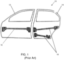
- FIG. 1 illustrates common side impact bars 16 and 18 for the front doors 12 and passenger doors 14, respectively.
- a side impact bar also known as an anti-intrusion bar or beam is a passive safety device, which is designed to protect passengers from side impacts. Side impacts are particularly dangerous since the location of impact is very close to the passenger, who can be immediately reached by the impacting vehicle.
- the role of the side impact bar is to absorb the kinetic energy of the colliding vehicles that is partially converted into internal work of the members involved in the crash.
- WO2010/071214 discloses a vehicle side door structure comprising an upper frame and an inner frame structure in mechanical communication with said upper frame, an outer body panel, and a composite reinforcement component positioned between said outer body panel and said upper frame and inner frame structure. More especially, the composite reinforcement component is reinforced with fibers but is a complex structure (Figure 6) made by pultrusion and having internal bracing that forms framed areas that are an upper hexagon and three lower triangles (central isosceles with bordering right triangles).
- a goal of the invention is to retain the safety requirements of a vehicle door with the door made both light but with less elements to reduce manufacturing and assembly costs.
- a vehicle door assembly is provided as defined in claim 1.
- the composite reinforcement component offers resistance to a side impact that limits intrusion into the passenger compartment.
- the composite reinforcement component is formed by stamping or resin transfer molding (RTM).
- the present invention has utility in the formation of a lightweight and simplified vehicle door assemblies compared to the prior art door assembly depicted in FIG. 1 .
- Inventive embodiments of the door assembly simplify the design of a vehicle door into four main components, an upper frame positioned about the window, an inner frame structure, an outer body panel, and a composite reinforcement component.
- Embodiments of the inventive composite reinforcement component provide an all-in-one solution for a side impact cross beam, as well as an upper door reinforcement, a front door pillar reinforcement, and a rear door pillar reinforcement.
- Embodiments of the composite reinforcement component act to reinforce the overall door structure, offers resistance to a side impact that limits the intrusion into the passenger compartment, and offers resistance to a frontal impact by maintaining the spacing between the vehicle A and B pillars (for a front door) and pillar C and D for a back door. It is appreciated that a coupé vehicle door in which there is no window frame (Corvette for example) is readily made based on the current invention.
- the composite reinforcement component has continuous or chopped fibers. Reinforcing fibers illustratively include glass, carbon, cellulosic materials, and combinations thereof.
- the composite reinforcement component is formed by stamping or resin transfer molding (RTM). It is noted that the inventive composite reinforcement component is molded as a single unified piece, as compared to the equivalent conventional construct in steel that is formed from more than four parts.
- Embodiments of the composite reinforcement component are compatible with door assemblies in which only a portion of a complete door is formed with composite materials such as the inner frame structure, the outer body panel and / or the upper frame, with the remaining door components being formed of conventional steel or aluminum constructs.
- FIG. 2 shows an exploded view of an inventive vehicle door assembly 50 with three primary components a combined upper and inner frame structure 52, a composite reinforcement component 56, and an outer body panel 54.
- FIG. 3 is an expanded perspective view of the composite reinforcement component 56 used in FIG. 2 according to embodiments of the invention.
- the upper portion 60 of the composite reinforcement component 56 provides reinforcement to the upper frame 52 part of the door assembly 50, and offers better resistance to a frontal crash and the resultant compressive forces.
- the left side 62 of the composite reinforcement component 56 increases the stiffness of the door assembly 50 in the lock area and the side cross beam 64.
- the primary function of the side cross beam 64 is to protect the driver or the passenger in a side impact accident.
- the right side 66 of the composite reinforcement component 56 increases the stiffness of the door assembly in the area of the hinges that secure the door to the vehicle frame, as well as increasing the stiffness of the side cross beam 64.
- components that are reinforced with chopped and dispersed glass fibers in the outer body panel 54 may have weight reducing glass microspheres that are joined by adhesives or mechanical fasteners to a second cured layer reinforced with dispersed carbon fibers or a combination of carbon, glass, and natural fibers in a resin transfer molding (RTM) formed epoxy matrix.
- Embodiments of the invention may have the outer layer body panel 54 formed using a class-A finish SMC illustratively including TCA ULTRALITE ® resins commercially available from Continental Structural Plastics, Inc. as disclosed in commonly owned U.S. Patent Publication 2005/0182205 , and with hollow glass microspheres as disclosed in U.S. Patent 9,018,280 both of which are included herein in their entirety.
- glass fiber may predominate as a fiber filler in the outer panel layer 54, there may be lesser amounts of carbon or natural fibers present.
- Embodiments of the vehicle door assembly 50 may be formed with a TCA ULTRALITE ® SMC outer 54 and carbon fiber or hybrid fiber epoxy RTM inner (52, 56) provides the following properties including: an assembly that is 10-15% lighter than aluminum, more cost effective than previous body part constructions, and an increased design flexibility.
- a cured inner portion of molding composition is reinforced predominantly with chopped carbon fibers is joined to a cured outer skin of a second sheet molding composition reinforced predominantly with glass fiber, where the outer surface has an automotive surface quality finish, such as a class-A finish.
- a class-A surface finish is associated with a surface shine and reflectivity required for exterior body panels by automotive manufacturers.
- the cured inner portion is substantially devoid of glass fiber, while the outer skin is substantially devoid of chopped carbon fiber.
- a class "A" surface as used herein is defined to be a cured SMC or BMC material amenable to painting to a surface gloss of a conventional production new vehicle per ASTM D523.
- a material containing unsaturated polyester resin, thermoplastic additives, organic peroxides, inhibitor, filler, mold release and pigment is sold by Continental Structural Plastics, Inc. under the trade name TCA ® .
- molding compositions refers to SMC, BMC and RTM resin formulations that are amenable to loading with chopped fibers of glass or carbon.
- carbon fibers in a molding composition are present in an inner layer of a vehicle door component containing from 10 to 40% by weight carbon fibers of the inner layer, with an outer skin layer of SMC based on the commercially available TCA ® or TCA ULTRALITE ® (Continental Structural Plastics, Inc.) containing glass fiber containing between 10 and 60% glass fiber by weight of the TCA ® portion, as embodied in U.S. Patent 7,655,297 .
- the ratio of thickness of the inner portion to the outer skin ranges from 01-10:1.
- the resulting SMC inner portion layer and outer skin layer are laid out, formed, and cured separately and the two layers joined thereafter to form a component.
- Such a door component with inner components (52, 56) containing carbon fibers is noted to have a density that is 10, 20, 30 and even 40% lower than the comparable article formed wholly from TCA ® or other class-A surface finish resin. In this way, a lightweight article is formed that retains the high surface gloss of a class-A surface.
- a given component in the door assembly may include both carbon fibers and glass fibers in combination, as well as other types of fibers such as natural cellulosic fibers that illustratively include coconut fibers with the proviso the loading of other types of fibers is limited such that glass fibers are predominantly present in the outer surface panel 54 and carbon fibers are predominantly present in the inner frame / structural components (52, 56).
- the predominant presence of a given type of fiber is used herein to mean that the fiber type represents more than 50% by weight of the total weight of fibers present in the layer.
- each layer is 100% of a given type of fiber, while in other embodiments the predominant fiber is present between 51 and 99%.
- range is intended to encompass not only the end point values of the range but also intermediate values of the range as explicitly being included within the range and varying by the last significant figure of the range.
- a recited range of from 1 to 4 is intended to include 1-2, 1-3, 2-4, 3-4, and 1-4.
- carbon fibers are dispersed in a methyl methacrylate monomer based molding composition.
- suitable monomers from which a molding composition formulation is produced illustratively include unsaturated polyesters, epoxies, and combinations thereof.
- a molding composition formulation based on epoxy illustratively includes bis-phenol-A and Novolac based 5 epoxy terminated resins.
- Suitable curing agents for such an epoxy based molding composition formulation illustratively include anhydrides such as trimellitic anhydride, methyl tetrahydrophthalic anhydride (MTHPA), nadic methyl anhydride (NMA), di- and tri-functional amines, and combinations thereof.
- carbon fibers are dispersed in a molding composition monomer or solution containing monomer with a relative polarity of greater than 0.26, and in certain embodiments greater than 0.5, and in still other embodiments between 0.5 and 0.8.
- Relative polarity is defined per Christian Reichardt, Solvents and Solvent Effects in Organic Chemistry, Wiley-VCH, 3rd edition, 2003 .
- the carbon fibers are dispersed in molding composition formulations prior to cure resulting in a reinforced SMC, BMC or RTM cured article that has a lower density overall, and a lower percentage by weight loading of fibers, as compared to a like layer formed with glass fiber reinforcement. Additionally, through the use of coupling agents superior tensile strength is achieved.
- heat is applied under suitable atmospheric conditions to remove any sizing or other conventional surface coatings on the surface of the carbon fibers prior to contact with a molding composition that upon cure forms a matrix containing the carbon fibers.
- heat is applied under an inert or reducing atmosphere to promote pyrolysis of the sizing from the core carbon fibers. It is appreciated that recycled carbon fiber is operative in an inventive two-piece vehicle component.
- joining bonding agents must have exceptional elongation ability to compensate for the differential CTLE of the joined layers over the temperature range of -40 to 140°F (-40 to 60°C), and even as high as 400°F (205°C) associated with cure conditions and hot joinder of layers.
- elastomeric bonding agents may be used to bond the inner layer to the outer layer.
- Elastomeric bonding agents operative herein to join disparate layers of an inventive component illustratively include urethanes, epoxies, and a combination thereof.
- the bonding flange thickness is increased from 1/4 - 1/2 inch (0.63 - 1.27 cm) for joining like fiber filler layers together to 1-1.5 inches (2.54 - 3.81 cm) for the inventive two-piece construction.
- the microspheroids used in the outer panel 54 have a mean diameter of between 12 and 45 microns. In still other inventive embodiments, the microspheroids have an outer dimension of between 16 and 45 microns.
- microspheroids are loaded into a base SMC or BMC class-A formulation from 2 to 20 total weight percent of the resulting formulation. The specific amount of microspheroids added into a given molding composition formulation is dependent on factors including desired article density, microspheroid size dispersion and mean particle dimension, required article strength, required article shrinkage, and required article surface smoothness.
- the microspheroids are pretreated with a surface coating adherent to the microspheroid surface.
- a microspheroid surface is readily derivatized to bond to a surrounding resin matrix during cure.
- the resulting article exhibits improved physical properties.
- One type of surface derivative for a microspheroid is a heteroatom functionally terminated thermoplastic coating.
- the heteroatom containing terminus illustratively includes a tertiary amine-, hydroxyl-, imine- or cyano-moiety. It is appreciated that such moieties under appropriate cure conditions known to the art are able to react with matrix resin components during cure to further strengthen a cured article.
- Tertiary amine terminated thermoplastic are readily prepared. D. H. Richards, D. M. Service, and M. J. Stewart, Br. Polym. J. 16, 117 (1984 ).
- a representative tertiary amine terminated thermoplastic is commercially available under the trade name ATBN 1300 X 21 from Noveon.
- a surface activating agent that bonds to a glass microspheroid is an alkoxysilane where the silane is reactive with the silica surface of the microspheroid.
- Representative alkoxysilane surface activating agents for the microspheroid illustratively include:
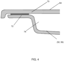
- FIG. 4 is a cross section of a typical body panel seal flange where the glass fiber based class A outer layer 54 is bonded 70 (adhesive, epoxy) or secured at a bond flange 72 of the carbon fiber based structural inner components (52, 56) according to embodiments of the invention.
- Vehicles are generally constructed around a frame, where a vehicle has finished surface panels that are secured or bonded to substructures to form body panels that are designed for attachment to the irregular surfaces of the frame.
- the bond flange 72 follows a corresponding seal carrying surface.
- the "hat" section 74 of the structural inner components (52, 56) extend to reach and attach to the frame (not shown).
Landscapes
- Engineering & Computer Science (AREA)
- Mechanical Engineering (AREA)
- Body Structure For Vehicles (AREA)
- Reinforced Plastic Materials (AREA)
- Laminated Bodies (AREA)
- Compositions Of Macromolecular Compounds (AREA)
Description
- The present invention in general relates to vehicle construction and, to a four-part door assembly with a composite reinforcement component.
- The use of fiber inclusions to strengthen a matrix is well known to the art. Well established mechanisms for the strengthening of a matrix include slowing and elongating the path of crack propagation through the matrix, as well as energy distribution associated with pulling a fiber free from the surrounding matrix material. In the context of sheet molding composition (SMC) formulations, bulk molding composition (BMC) formulations, and resin transfer molding (RTM) fiber strengthening has traditionally involved usage of chopped glass fibers. There is a growing appreciation in the field of molding compositions that replacing in part, or all of the glass fiber in molding compositions with carbon fiber can provide improved component properties; however, technical problems remain that include disparate layer joinder, fiber flow, fiber surface energies, and surface quality of the resultant component.
- The use of carbon fibers in composites, sheet molding compositions, and resin transfer molding (RTM) results in formed components with a lower weight as compared to glass fiber reinforced materials. The weight savings achieved with carbon fiber reinforcement stems from the fact that carbon has a lower density than glass and produces stronger and stiffer parts at a given thickness.
- Weight savings in the auto, transportation, and logistics based industries has been a major focus in order to make more fuel efficient vehicles both for ground and air transport. Weight savings using carbon reinforced composites in vehicle parts has helped these industries achieve meaningful weight savings. However, high quality surface finishes, such as a class-A surfaces in the auto industry that are characterized by a high surface sheen, are generally obtained only with highly tailored resin formulations that contain glass fibers, such as TCA® and TCA Ultralite® resins commercially available from Continental Structural Plastics, Inc. used in SMC or RTM, or metals such as aluminum and alloys thereof. Class-A surfaces are generally required for vehicle surface panels: doors, hoods, quarter panels, trunks, roof structures, bumpers, etc., which make up a significant amount of weight in a vehicle.
- Furthermore, in the continuum of processes to lighten vehicle body panels, steel thickness was reduced and then supplanted with lower density materials such as aluminum and resin based materials. Evidence is developing that aluminum has several limitations that favor resin based vehicle body articles. It now appears that the material costs, forming costs and the tensile strength of aluminum at the thicknesses needed to achieve ever lighter body panels create a collective limitation. In contrast, resin based articles can be tailored by changes in resin chemistry and additives to meet a range of requirements. Additionally, while metal forming of complex shapes requires several steps, a well-designed mold can impart complex shapes in a single step.
- Presently, passenger vehicle doors are constructed from many subcomponents which are required due to the complex geometries of the door assembly.
FIG. 1 illustrates commonside impact bars front doors 12 andpassenger doors 14, respectively. A side impact bar also known as an anti-intrusion bar or beam is a passive safety device, which is designed to protect passengers from side impacts. Side impacts are particularly dangerous since the location of impact is very close to the passenger, who can be immediately reached by the impacting vehicle. The role of the side impact bar is to absorb the kinetic energy of the colliding vehicles that is partially converted into internal work of the members involved in the crash. - The many subcomponents required to build a passenger vehicle door increases manufacturing times and costs, and decreases the overall reliability of the door assembly overtime. Furthermore, the typical overall weight of the door is over fifteen kilograms. Vehicle manufactures as previously noted are always looking to lighten assemblies while also maintaining or improving vehicle occupant safety.
- Thus, there exists a need for a door design that utilizes composite materials to lower the weight of the door assembly, while improving the safety performance and manufacturability.
- Publication
WO2010/071214 discloses a vehicle side door structure comprising an upper frame and an inner frame structure in mechanical communication with said upper frame, an outer body panel, and a composite reinforcement component positioned between said outer body panel and said upper frame and inner frame structure. More especially, the composite reinforcement component is reinforced with fibers but is a complex structure (Figure 6) made by pultrusion and having internal bracing that forms framed areas that are an upper hexagon and three lower triangles (central isosceles with bordering right triangles). - A goal of the invention is to retain the safety requirements of a vehicle door with the door made both light but with less elements to reduce manufacturing and assembly costs.
- A vehicle door assembly is provided as defined in claim 1. The composite reinforcement component offers resistance to a side impact that limits intrusion into the passenger compartment. The composite reinforcement component is formed by stamping or resin transfer molding (RTM).
- The present invention is further detailed with respect to the following drawings that are intended to show certain aspects of the present invention, but should not be construed as a limit on the practice of the present invention.
-
FIG. 1 is an existing prior art passenger vehicle door assemblies showing side impact bars; -
FIG. 2 is an exploded view of a door assembly with a composite reinforcement component according to embodiments of the invention; -
FIG. 3 is an expanded perspective view of the composite reinforcement component used inFIG. 2 according to embodiments of the invention; and -
FIG. 4 is a cross section of a typical body panel seal flange where the glass fiber based class-A outer panel is bonded (adhesive, epoxy, etc.) or secured at a bond flange of the carbon or hybrid fiber based structural inner panel according to embodiments of the invention. - The present invention has utility in the formation of a lightweight and simplified vehicle door assemblies compared to the prior art door assembly depicted in
FIG. 1 . Inventive embodiments of the door assembly simplify the design of a vehicle door into four main components, an upper frame positioned about the window, an inner frame structure, an outer body panel, and a composite reinforcement component. Embodiments of the inventive composite reinforcement component provide an all-in-one solution for a side impact cross beam, as well as an upper door reinforcement, a front door pillar reinforcement, and a rear door pillar reinforcement. Embodiments of the composite reinforcement component act to reinforce the overall door structure, offers resistance to a side impact that limits the intrusion into the passenger compartment, and offers resistance to a frontal impact by maintaining the spacing between the vehicle A and B pillars (for a front door) and pillar C and D for a back door. It is appreciated that a coupé vehicle door in which there is no window frame (Corvette for example) is readily made based on the current invention. - The composite reinforcement component has continuous or chopped fibers. Reinforcing fibers illustratively include glass, carbon, cellulosic materials, and combinations thereof. The composite reinforcement component is formed by stamping or resin transfer molding (RTM). It is noted that the inventive composite reinforcement component is molded as a single unified piece, as compared to the equivalent conventional construct in steel that is formed from more than four parts. Embodiments of the composite reinforcement component are compatible with door assemblies in which only a portion of a complete door is formed with composite materials such as the inner frame structure, the outer body panel and / or the upper frame, with the remaining door components being formed of conventional steel or aluminum constructs.
- Referring now to the figures,
FIG. 2 shows an exploded view of an inventivevehicle door assembly 50 with three primary components a combined upper andinner frame structure 52, acomposite reinforcement component 56, and anouter body panel 54. -
FIG. 3 is an expanded perspective view of thecomposite reinforcement component 56 used inFIG. 2 according to embodiments of the invention. Theupper portion 60 of thecomposite reinforcement component 56 provides reinforcement to theupper frame 52 part of thedoor assembly 50, and offers better resistance to a frontal crash and the resultant compressive forces. Theleft side 62 of thecomposite reinforcement component 56 increases the stiffness of thedoor assembly 50 in the lock area and theside cross beam 64. The primary function of theside cross beam 64 is to protect the driver or the passenger in a side impact accident. Theright side 66 of thecomposite reinforcement component 56 increases the stiffness of the door assembly in the area of the hinges that secure the door to the vehicle frame, as well as increasing the stiffness of theside cross beam 64. - In specific embodiments components that are reinforced with chopped and dispersed glass fibers in the
outer body panel 54 may have weight reducing glass microspheres that are joined by adhesives or mechanical fasteners to a second cured layer reinforced with dispersed carbon fibers or a combination of carbon, glass, and natural fibers in a resin transfer molding (RTM) formed epoxy matrix. Embodiments of the invention may have the outerlayer body panel 54 formed using a class-A finish SMC illustratively including TCA ULTRALITE® resins commercially available from Continental Structural Plastics, Inc. as disclosed in commonly ownedU.S. Patent Publication 2005/0182205 , and with hollow glass microspheres as disclosed inU.S. Patent 9,018,280 - It is noted that while glass fiber may predominate as a fiber filler in the
outer panel layer 54, there may be lesser amounts of carbon or natural fibers present. - Embodiments of the
vehicle door assembly 50 may be formed with a TCA ULTRALITE® SMC outer 54 and carbon fiber or hybrid fiber epoxy RTM inner (52, 56) provides the following properties including: an assembly that is 10-15% lighter than aluminum, more cost effective than previous body part constructions, and an increased design flexibility. - In certain inventive embodiments, a cured inner portion of molding composition is reinforced predominantly with chopped carbon fibers is joined to a cured outer skin of a second sheet molding composition reinforced predominantly with glass fiber, where the outer surface has an automotive surface quality finish, such as a class-A finish. As used herein, a class-A surface finish is associated with a surface shine and reflectivity required for exterior body panels by automotive manufacturers. In an embodiment, the cured inner portion is substantially devoid of glass fiber, while the outer skin is substantially devoid of chopped carbon fiber.
- A class "A" surface as used herein is defined to be a cured SMC or BMC material amenable to painting to a surface gloss of a conventional production new vehicle per ASTM D523. Such a material containing unsaturated polyester resin, thermoplastic additives, organic peroxides, inhibitor, filler, mold release and pigment is sold by Continental Structural Plastics, Inc. under the trade name TCA®.
- As used herein "molding compositions" refers to SMC, BMC and RTM resin formulations that are amenable to loading with chopped fibers of glass or carbon.
- In a particular inventive embodiment, carbon fibers in a molding composition are present in an inner layer of a vehicle door component containing from 10 to 40% by weight carbon fibers of the inner layer, with an outer skin layer of SMC based on the commercially available TCA® or TCA ULTRALITE® (Continental Structural Plastics, Inc.) containing glass fiber containing between 10 and 60% glass fiber by weight of the TCA® portion, as embodied in
U.S. Patent 7,655,297 . The ratio of thickness of the inner portion to the outer skin ranges from 01-10:1. The resulting SMC inner portion layer and outer skin layer are laid out, formed, and cured separately and the two layers joined thereafter to form a component. Such a door component with inner components (52, 56) containing carbon fibers is noted to have a density that is 10, 20, 30 and even 40% lower than the comparable article formed wholly from TCA® or other class-A surface finish resin. In this way, a lightweight article is formed that retains the high surface gloss of a class-A surface. It is appreciated that a given component in the door assembly, may include both carbon fibers and glass fibers in combination, as well as other types of fibers such as natural cellulosic fibers that illustratively include coconut fibers with the proviso the loading of other types of fibers is limited such that glass fibers are predominantly present in theouter surface panel 54 and carbon fibers are predominantly present in the inner frame / structural components (52, 56). The predominant presence of a given type of fiber is used herein to mean that the fiber type represents more than 50% by weight of the total weight of fibers present in the layer. In certain embodiments, each layer is 100% of a given type of fiber, while in other embodiments the predominant fiber is present between 51 and 99%. - It is to be understood that in instances where a range of values are provided that the range is intended to encompass not only the end point values of the range but also intermediate values of the range as explicitly being included within the range and varying by the last significant figure of the range. By way of example, a recited range of from 1 to 4 is intended to include 1-2, 1-3, 2-4, 3-4, and 1-4.
- In another inventive embodiment, carbon fibers are dispersed in a methyl methacrylate monomer based molding composition. Other suitable monomers from which a molding composition formulation is produced illustratively include unsaturated polyesters, epoxies, and combinations thereof. A molding composition formulation based on epoxy illustratively includes bis-phenol-A and Novolac based 5 epoxy terminated resins. Suitable curing agents for such an epoxy based molding composition formulation illustratively include anhydrides such as trimellitic anhydride, methyl tetrahydrophthalic anhydride (MTHPA), nadic methyl anhydride (NMA), di- and tri-functional amines, and combinations thereof.
- In another inventive embodiment of the present invention, carbon fibers are dispersed in a molding composition monomer or solution containing monomer with a relative polarity of greater than 0.26, and in certain embodiments greater than 0.5, and in still other embodiments between 0.5 and 0.8. Relative polarity is defined per Christian Reichardt, Solvents and Solvent Effects in Organic Chemistry, Wiley-VCH, 3rd edition, 2003.
- In another inventive embodiment, the carbon fibers are dispersed in molding composition formulations prior to cure resulting in a reinforced SMC, BMC or RTM cured article that has a lower density overall, and a lower percentage by weight loading of fibers, as compared to a like layer formed with glass fiber reinforcement. Additionally, through the use of coupling agents superior tensile strength is achieved.
- In certain inventive embodiments, heat is applied under suitable atmospheric conditions to remove any sizing or other conventional surface coatings on the surface of the carbon fibers prior to contact with a molding composition that upon cure forms a matrix containing the carbon fibers. In still other inventive embodiments heat is applied under an inert or reducing atmosphere to promote pyrolysis of the sizing from the core carbon fibers. It is appreciated that recycled carbon fiber is operative in an inventive two-piece vehicle component.
- As carbon dissipates heat much better than glass as known from the respective coefficients of linear thermal expansion (CLTE), a predominantly carbon fiber filled layer cools more quickly than an otherwise like layer predominantly glass fiber filled. This difference in dynamic cooling after cure is compounded for thinner carbon fiber filled layers making them especially prone to warpage. Therefore, due to the differences in CTLE and material stiffness between the predominantly glass fiber filled layer and predominantly carbon filled layer, joining bonding agents must have exceptional elongation ability to compensate for the differential CTLE of the joined layers over the temperature range of -40 to 140°F (-40 to 60°C), and even as high as 400°F (205°C) associated with cure conditions and hot joinder of layers. In specific inventive embodiments, elastomeric bonding agents may be used to bond the inner layer to the outer layer. Elastomeric bonding agents operative herein to join disparate layers of an inventive component illustratively include urethanes, epoxies, and a combination thereof. In certain inventive embodiments, the bonding flange thickness is increased from 1/4 - 1/2 inch (0.63 - 1.27 cm) for joining like fiber filler layers together to 1-1.5 inches (2.54 - 3.81 cm) for the inventive two-piece construction.
- In some inventive embodiments, the microspheroids used in the
outer panel 54 have a mean diameter of between 12 and 45 microns. In still other inventive embodiments, the microspheroids have an outer dimension of between 16 and 45 microns. Typically, microspheroids are loaded into a base SMC or BMC class-A formulation from 2 to 20 total weight percent of the resulting formulation. The specific amount of microspheroids added into a given molding composition formulation is dependent on factors including desired article density, microspheroid size dispersion and mean particle dimension, required article strength, required article shrinkage, and required article surface smoothness. - In a particularly preferred embodiment of the present invention, the microspheroids are pretreated with a surface coating adherent to the microspheroid surface.
- A microspheroid surface is readily derivatized to bond to a surrounding resin matrix during cure. The resulting article exhibits improved physical properties.
- One type of surface derivative for a microspheroid is a heteroatom functionally terminated thermoplastic coating. The heteroatom containing terminus illustratively includes a tertiary amine-, hydroxyl-, imine- or cyano-moiety. It is appreciated that such moieties under appropriate cure conditions known to the art are able to react with matrix resin components during cure to further strengthen a cured article. Tertiary amine terminated thermoplastic are readily prepared. D. H. Richards, D. M. Service, and M. J. Stewart, Br. Polym. J. 16, 117 (1984). A representative tertiary amine terminated thermoplastic is commercially available under the trade name ATBN 1300 X 21 from Noveon.
- A surface activating agent that bonds to a glass microspheroid is an alkoxysilane where the silane is reactive with the silica surface of the microspheroid. Representative alkoxysilane surface activating agents for the microspheroid illustratively include:
- 3-aminopropyltrimethoxysilane, 3-aminopropyltriethoxysilane, 3-glycidoxypropyltrimethoxysilane, 3-glycidoxypropyltriethoxysilane, (3-glycidoxypropyl) bis(trimethylsiloxy)methylsilane, (3-glycidoxypropyl)methyldiethoxysilane, (3-glycidoxypropyl) dimethylethoxysilane, (3-glycidoxypropyl)methyldimethoxysilane, methacryloxymethyltriethoxysilane, methacryloxymethyltrimethoxysilane, methacryloxypropyldimethylethoxysilane, methacryloxypropyldimethylmethoxysilane, ethacryloxypropylmethyldimethoxysilane, methacryloxypropyltriethoxysilane, methoxymethyltrimethylsilane, 3-methoxypropyltrimethoxysilane, 3-methacryloxypropyldimethylchlorosilane, methacryloxypropylmethyldichlorosilane, methacryloxypropyltrichlorosilane, 3-isocyanatopropyldimethylchlorosilane, 3-isocyanatopropyltriethoxysilane, bis(3-triethoxysilylpropyl)tetrasulfide, and combinations thereof. In some inventive embodiments, the silane surface activating agent includes an ethenically unsaturated moiety that is reactive under free radical cross-linking conditions so as to covalently bond with the hollow glass microsphere to the surrounding SMC or BMC class-A matrix.
-
FIG. 4 is a cross section of a typical body panel seal flange where the glass fiber based class Aouter layer 54 is bonded 70 (adhesive, epoxy) or secured at abond flange 72 of the carbon fiber based structural inner components (52, 56) according to embodiments of the invention. Vehicles are generally constructed around a frame, where a vehicle has finished surface panels that are secured or bonded to substructures to form body panels that are designed for attachment to the irregular surfaces of the frame. Thebond flange 72 follows a corresponding seal carrying surface. The "hat"section 74 of the structural inner components (52, 56) extend to reach and attach to the frame (not shown). - The foregoing description is illustrative of particular embodiments of the invention, but is not meant to be a limitation upon the practice thereof. The following claims define the scope of the invention.
Claims (8)
- A vehicle door assembly (50) comprising:an upper frame (52);an inner frame structure (52) in mechanical communication with said upper frame and forming a combined upper frame and inner frame structure (52);an outer body panel (54); anda composite reinforcement component (56) positioned between said outer body panel and a lower section of said combined upper and inner frame structure,wherein said composite reinforcement component (56) is molded as a single piece and constituted by an upper portion (60) that provides reinforcement to the upper frame (52) part of the door assembly, by a side cross beam (64) that is a lower portion of the composite reinforcement component, by a left side (62) that increases the stiffness of the door assembly in a lock area and the stiffness of the side cross beam, and by a right side (66) that increases the stiffness of the door assembly in an area of a set of hinges that secure the door assembly to a frame of the vehicle and the stiffness of a side cross beam, and wherein said composite reinforcement component (56) is reinforced with continuous or chopped fibers and is formed by stamping or resin transfer molding (RTM), wherein the combined upper frame and inner frame structure (52) and the composite reinforcement component (56) have a "hat" section (74) that extends at bond flange (72), and wherein the outer body panel (54) is bonded (70) or secured at said bond flange (72).
- The vehicle door assembly of claim 1 wherein said composite reinforcement component (56) offers resistance to a side impact that limits intrusion into the passenger compartment.
- The vehicle door assembly of claim 1 wherein said composite reinforcement component (56) offers resistance to a frontal impact by maintaining a spacing between vehicle pillars A and B or pillars C and D for a front door or a back door, respectively.
- The vehicle door assembly of claim 1 wherein the continuous or chopped fibers are at least one of glass, carbon, cellulosic materials, or a combination thereof.
- The vehicle door assembly of any one of claims 1 to 4 wherein said composite reinforcement component (56) are compatible with door assemblies where just part of the door assembly is formed with composite materials, where at least one of the inner frame structure, the outer body panel, or the upper frame are made in steel or aluminum.
- The vehicle door assembly of any one of claims 1 to 4 wherein said composite reinforcement component (56) performs an all-in-one solution for a side impact cross beam, an upper door reinforcement, a front door pillar reinforcement, and a rear door pillar reinforcement.
- The vehicle door assembly of any one of claims 1 to 4 wherein said upper frame (52) is positioned about a window.
- The vehicle door assembly of any one of claims 1 to 4 wherein said upper frame (52) defines the top of a coupé door.
Applications Claiming Priority (2)
| Application Number | Priority Date | Filing Date | Title |
|---|---|---|---|
| US201662385493P | 2016-09-09 | 2016-09-09 | |
| PCT/US2017/050939 WO2018049319A1 (en) | 2016-09-09 | 2017-09-11 | Composite vehicle door components formed by sheet molding compound-resin transfer molding assemblies |
Publications (3)
| Publication Number | Publication Date |
|---|---|
| EP3509882A1 EP3509882A1 (en) | 2019-07-17 |
| EP3509882A4 EP3509882A4 (en) | 2020-04-22 |
| EP3509882B1 true EP3509882B1 (en) | 2024-04-24 |
Family
ID=61562143
Family Applications (1)
| Application Number | Title | Priority Date | Filing Date |
|---|---|---|---|
| EP17849715.2A Active EP3509882B1 (en) | 2016-09-09 | 2017-09-11 | Composite vehicle door components formed by sheet molding compound-resin transfer molding assemblies |
Country Status (8)
| Country | Link |
|---|---|
| US (1) | US11529851B2 (en) |
| EP (1) | EP3509882B1 (en) |
| JP (1) | JP7020755B2 (en) |
| CN (1) | CN109715424A (en) |
| CA (1) | CA3030696A1 (en) |
| MX (1) | MX2019002758A (en) |
| PT (1) | PT3509882T (en) |
| WO (1) | WO2018049319A1 (en) |
Families Citing this family (11)
| Publication number | Priority date | Publication date | Assignee | Title |
|---|---|---|---|---|
| KR20210068562A (en) * | 2018-10-08 | 2021-06-09 | 브로제 파초이크타일레 에스이 운트 코. 콤만디트게젤샤프트, 밤베르크 | Door module for vehicle door, vehicle door and manufacturing method |
| CN113631402A (en) * | 2019-03-11 | 2021-11-09 | 帝人株式会社 | Composite vehicle component formed from sheet molding compound reinforced with continuous fibers |
| JP7487452B2 (en) | 2019-07-23 | 2024-05-21 | マツダ株式会社 | Vehicle body structure |
| JP7532751B2 (en) * | 2019-07-23 | 2024-08-14 | マツダ株式会社 | Vehicle body structure |
| JP7487453B2 (en) * | 2019-07-23 | 2024-05-21 | マツダ株式会社 | Vehicle body structure |
| JP7487451B2 (en) | 2019-07-23 | 2024-05-21 | マツダ株式会社 | Vehicle body structure |
| JP7484100B2 (en) * | 2019-07-23 | 2024-05-16 | マツダ株式会社 | Vehicle body structure |
| WO2021086564A1 (en) * | 2019-10-30 | 2021-05-06 | Teijin Limited | Shock absorption vehicle reinforcing component |
| CN112977017A (en) * | 2019-12-02 | 2021-06-18 | 西安新三力汽车零部件有限公司 | Automobile door plate made of SMC composite material based on graphene |
| DE102020119196A1 (en) * | 2020-07-21 | 2022-01-27 | Bayerische Motoren Werke Aktiengesellschaft | Outer skin component for a motor vehicle and method for producing an outer skin component |
| DE102021114962A1 (en) * | 2021-06-10 | 2022-12-15 | Universität Siegen, Körperschaft des öffentlichen Rechts | Hybrid vehicle door |
Citations (3)
| Publication number | Priority date | Publication date | Assignee | Title |
|---|---|---|---|---|
| DE19860556A1 (en) * | 1997-12-24 | 1999-07-15 | Suzuki Motor Co | Rear end bodywork structure for estate cars (station wagons) |
| EP1327545A2 (en) * | 2002-01-10 | 2003-07-16 | DaimlerChrysler AG | Door or lid for vehicle |
| WO2014210310A1 (en) * | 2013-06-26 | 2014-12-31 | Continental Structural Plastics, Inc. | Two piece bonded assembly vehicle components |
Family Cites Families (48)
| Publication number | Priority date | Publication date | Assignee | Title |
|---|---|---|---|---|
| JPH01103417U (en) * | 1987-12-28 | 1989-07-12 | ||
| US4945682A (en) * | 1989-12-04 | 1990-08-07 | General Motors Corporation | Plastic motor vehicle door |
| JP2962036B2 (en) * | 1992-04-16 | 1999-10-12 | 日産自動車株式会社 | Car door structure |
| US5536060A (en) * | 1995-02-17 | 1996-07-16 | General Motors Corporation | Reinforced vehicle door |
| DE19530941B4 (en) * | 1995-08-23 | 2005-08-25 | Wagon Automotive Gmbh | Vehicle door with a mirror triangle provided for mounting an exterior mirror |
| US6196619B1 (en) * | 1995-12-22 | 2001-03-06 | Joalto Design, Inc. | Vehicle closure panel having an intrusion beam as primary structure |
| US5908216A (en) * | 1995-12-22 | 1999-06-01 | Joalto Design, Inc. | Side intrusion beam with four points of connection |
| JP2000016194A (en) | 1998-07-07 | 2000-01-18 | Fujikura Ltd | Automobile door, automobile door wire harness, and method of manufacturing the same |
| US6164716A (en) * | 1998-12-18 | 2000-12-26 | Daimlerchrysler Corporation | Energy dissipating body panel assembly |
| GB9919297D0 (en) * | 1999-08-17 | 1999-10-20 | Meritor Light Vehicle Sys Ltd | Door reinforcement device |
| US6176542B1 (en) * | 1999-09-30 | 2001-01-23 | Delphi Technologies, Inc. | Vehicle door |
| DE10052739A1 (en) * | 2000-10-25 | 2002-05-16 | Brose Fahrzeugteile | Door for a motor vehicle comprises a support plate having an upper contour supporting a channel seal whose ends are connected to the lateral sealing regions of the support plate |
| DE10060632A1 (en) * | 2000-12-06 | 2002-07-04 | Gerald Fellner | vehicle door |
| DE10126250A1 (en) * | 2001-05-29 | 2002-12-12 | Sai Automotive Sal Gmbh | Door frame for a vehicle door |
| JP2003335134A (en) | 2002-05-17 | 2003-11-25 | Mazda Motor Corp | Automotive door and method of manufacturing the same |
| US6928735B2 (en) | 2002-07-26 | 2005-08-16 | General Motors Corporation | Method of vehicle door assembly |
| SE523365C2 (en) * | 2002-08-08 | 2004-04-13 | Ssab Hardtech Ab | Vehicle |
| JP2004320616A (en) | 2003-04-18 | 2004-11-11 | Pioneer Electronic Corp | Speaker mounting panel and speaker device |
| US6805397B1 (en) * | 2003-04-30 | 2004-10-19 | General Motors Corporation | Vehicle door |
| US20050182205A1 (en) | 2004-02-17 | 2005-08-18 | Guha Probir K. | Polymeric thickener for molding compounds |
| WO2005084247A2 (en) | 2004-02-27 | 2005-09-15 | General Motors Corporation | Mixed metal closure assembly and method |
| US7700670B2 (en) | 2005-05-13 | 2010-04-20 | Beach Brian A | Low-density molding compound |
| US20070222256A1 (en) * | 2006-03-23 | 2007-09-27 | Jeffrey Valentage | Hybrid door core and trim module with integrated components |
| US7655297B2 (en) | 2006-10-19 | 2010-02-02 | Continental Structural Plastics | Electrically conductive polyester molding composition having a high quality surface finish |
| EP2167338B1 (en) * | 2007-07-09 | 2011-12-28 | ThyssenKrupp System Engineering GmbH | Door of a motor vehicle |
| JP5035218B2 (en) | 2007-12-27 | 2012-09-26 | 豊田合成株式会社 | Automotive door |
| US8033592B2 (en) * | 2008-08-27 | 2011-10-11 | GM Global Technology Operations LLC | Door assembly and method for a vehicle |
| JP4712854B2 (en) * | 2008-10-23 | 2011-06-29 | 本田技研工業株式会社 | Rear door structure |
| JP2012061869A (en) | 2008-12-15 | 2012-03-29 | Teijin Ltd | Vertical panel part for vehicle |
| DE102010014510A1 (en) * | 2010-04-10 | 2011-10-13 | Daimler Ag | Door for a motor vehicle and process for its manufacture |
| US8511740B2 (en) * | 2011-03-09 | 2013-08-20 | Nissan North America, Inc. | Vehicle door reinforcement |
| EP2742256B1 (en) * | 2011-06-10 | 2020-02-19 | Henkel AG & Co. KGaA | Effective vibration damping across a broad temperature range |
| JP5883595B2 (en) * | 2011-09-09 | 2016-03-15 | シロキ工業株式会社 | Vehicle door and method for manufacturing vehicle door |
| UA112663C2 (en) * | 2011-09-30 | 2016-10-10 | Арселормітталь Інвестігасіон І Десаррольо, С.Л. | VEHICLE STEEL DOORS FOR THE VEHICLE AND THE METHOD FOR THEIR MANUFACTURING |
| DE102011121727A1 (en) * | 2011-12-20 | 2013-06-20 | Gm Global Technology Operations, Llc | Door framework for vehicle door, has base structure formed by metal part i.e. transformed sheet metal part, formed by stamping and made of aluminum or aluminum alloy and/or magnesium or magnesium alloy |
| DE202012102178U1 (en) * | 2012-06-13 | 2013-09-18 | Carcoustics Techconsult Gmbh | Distance device for stacking identically shaped plastic moldings |
| US9010839B2 (en) * | 2012-10-24 | 2015-04-21 | Sabic Global Technologies B.V. | Vehicle side door structure and method of making and using the same |
| FR3001921B1 (en) * | 2013-02-13 | 2015-02-20 | Renault Sa | OPENING STRUCTURE OF PLASTIC MATERIAL DELIMITATING A HOLLOW BODY |
| FR3001920B1 (en) | 2013-02-13 | 2016-07-15 | Renault Sas | PLASTIC RIGIDIFICATION PANEL FOR OPENING WITH FIXING A WINDOW LIFTING SYSTEM |
| EP2818347B1 (en) * | 2013-06-27 | 2019-08-07 | Volvo Car Corporation | Connection arrangement for releasable connection of a first and a second portion of a side collision safety structure of a vehicle |
| US9550466B2 (en) * | 2014-03-05 | 2017-01-24 | Toyota Motor Engineering & Manufacturing North America, Inc. | Morphing energy absorber system for a vehicle assembly |
| EP3130457B1 (en) | 2014-04-11 | 2018-05-30 | Nissan Motor Co., Ltd | Shock absorption mechanism and vehicle exterior plate member provided with same |
| DE102014008250A1 (en) * | 2014-06-04 | 2015-12-17 | GM GLOBAL TECHNOLOGY OPERATION LLC (n. d. Ges. d. Staates Delaware) | Frame structure for a vehicle door, in particular a tailgate of a vehicle |
| JP6318977B2 (en) | 2014-08-22 | 2018-05-09 | トヨタ自動車株式会社 | Manufacturing method of component assembly |
| US20160096418A1 (en) * | 2014-10-06 | 2016-04-07 | GM Global Technology Operations LLC | Stiffeners for cast light-metal door headers |
| KR101724966B1 (en) | 2015-12-10 | 2017-04-07 | 현대자동차주식회사 | Manufacturing method of door for vehicle, and door for vehicle manufactured by method thereof |
| EP3312033B1 (en) * | 2016-10-21 | 2020-07-29 | Magna Steyr Fahrzeugtechnik AG & Co KG | Vehicle door |
| JP7124302B2 (en) * | 2017-11-30 | 2022-08-24 | トヨタ紡織株式会社 | vehicle door |
-
2017
- 2017-09-11 JP JP2019513824A patent/JP7020755B2/en active Active
- 2017-09-11 WO PCT/US2017/050939 patent/WO2018049319A1/en not_active Ceased
- 2017-09-11 PT PT178497152T patent/PT3509882T/en unknown
- 2017-09-11 EP EP17849715.2A patent/EP3509882B1/en active Active
- 2017-09-11 MX MX2019002758A patent/MX2019002758A/en unknown
- 2017-09-11 US US16/332,235 patent/US11529851B2/en active Active
- 2017-09-11 CN CN201780052942.6A patent/CN109715424A/en active Pending
- 2017-09-11 CA CA3030696A patent/CA3030696A1/en active Pending
Patent Citations (3)
| Publication number | Priority date | Publication date | Assignee | Title |
|---|---|---|---|---|
| DE19860556A1 (en) * | 1997-12-24 | 1999-07-15 | Suzuki Motor Co | Rear end bodywork structure for estate cars (station wagons) |
| EP1327545A2 (en) * | 2002-01-10 | 2003-07-16 | DaimlerChrysler AG | Door or lid for vehicle |
| WO2014210310A1 (en) * | 2013-06-26 | 2014-12-31 | Continental Structural Plastics, Inc. | Two piece bonded assembly vehicle components |
Also Published As
| Publication number | Publication date |
|---|---|
| EP3509882A1 (en) | 2019-07-17 |
| JP2019526494A (en) | 2019-09-19 |
| US20190217689A1 (en) | 2019-07-18 |
| EP3509882A4 (en) | 2020-04-22 |
| PT3509882T (en) | 2024-06-20 |
| CN109715424A (en) | 2019-05-03 |
| JP7020755B2 (en) | 2022-02-16 |
| WO2018049319A1 (en) | 2018-03-15 |
| MX2019002758A (en) | 2019-06-17 |
| US11529851B2 (en) | 2022-12-20 |
| CA3030696A1 (en) | 2018-03-15 |
Similar Documents
| Publication | Publication Date | Title |
|---|---|---|
| EP3509882B1 (en) | Composite vehicle door components formed by sheet molding compound-resin transfer molding assemblies | |
| EP3013670B1 (en) | Two piece bonded assembly vehicle components | |
| JP6801825B2 (en) | Structural members for vehicles | |
| CA2454343C (en) | Composite component integration panel | |
| US20190381749A1 (en) | Two piece bonded vehicle components formed by sheet molding compound-resin transfer molding assemblies | |
| US20140065427A1 (en) | Vehicle component including basalt and method for making same | |
| JP6969674B2 (en) | Automotive structural members | |
| Bruderick et al. | Applications of carbon fiber SMC for the Dodge Viper | |
| JP2019182168A (en) | Center pillar inner and center pillar | |
| JP2011020614A (en) | Hood panel for automobile | |
| WO2019198672A1 (en) | T-shaped joint structure | |
| US20210146667A1 (en) | Inhibition of bond-line read-through in joined dual layer thermoset articles | |
| Bruderick et al. | Applications of carbon/fiber SMC for the 2003 Dodge Viper | |
| Sankararao et al. | Enactment of Fiber Reniforced Hybrid Epoxy Composite for Passenger Car Bumper Beam | |
| WO2019198673A1 (en) | T-shaped joint structure | |
| JP7087768B2 (en) | Structural members for vehicles | |
| Vivekanandan et al. | Selection of alternative material for car roof panel | |
| JP7107055B2 (en) | Vehicle structural member | |
| WO2022176661A1 (en) | Impact-absorbing member | |
| WO2021086564A1 (en) | Shock absorption vehicle reinforcing component | |
| KR20020085252A (en) | A Thermosetting Resin Composition of Plastic Door for Automobile and Methods for preparing the same |
Legal Events
| Date | Code | Title | Description |
|---|---|---|---|
| STAA | Information on the status of an ep patent application or granted ep patent |
Free format text: STATUS: THE INTERNATIONAL PUBLICATION HAS BEEN MADE |
|
| PUAI | Public reference made under article 153(3) epc to a published international application that has entered the european phase |
Free format text: ORIGINAL CODE: 0009012 |
|
| STAA | Information on the status of an ep patent application or granted ep patent |
Free format text: STATUS: REQUEST FOR EXAMINATION WAS MADE |
|
| 17P | Request for examination filed |
Effective date: 20190111 |
|
| AK | Designated contracting states |
Kind code of ref document: A1 Designated state(s): AL AT BE BG CH CY CZ DE DK EE ES FI FR GB GR HR HU IE IS IT LI LT LU LV MC MK MT NL NO PL PT RO RS SE SI SK SM TR |
|
| AX | Request for extension of the european patent |
Extension state: BA ME |
|
| RIN1 | Information on inventor provided before grant (corrected) |
Inventor name: BOYER, DOMINIQUE Inventor name: TOITGANS, MARC-PHILIPPE Inventor name: BONTE, PHILIPPE |
|
| DAV | Request for validation of the european patent (deleted) | ||
| DAX | Request for extension of the european patent (deleted) | ||
| RIN1 | Information on inventor provided before grant (corrected) |
Inventor name: TOITGANS, MARC-PHILIPPE Inventor name: BONTE, PHILIPPE Inventor name: BOYER, DOMINIQUE |
|
| A4 | Supplementary search report drawn up and despatched |
Effective date: 20200324 |
|
| RIC1 | Information provided on ipc code assigned before grant |
Ipc: B60J 5/04 20060101AFI20200318BHEP |
|
| STAA | Information on the status of an ep patent application or granted ep patent |
Free format text: STATUS: EXAMINATION IS IN PROGRESS |
|
| 17Q | First examination report despatched |
Effective date: 20210414 |
|
| RAP3 | Party data changed (applicant data changed or rights of an application transferred) |
Owner name: TEIJIN AUTOMOTIVE TECHNOLOGIES, INC. |
|
| GRAP | Despatch of communication of intention to grant a patent |
Free format text: ORIGINAL CODE: EPIDOSNIGR1 |
|
| STAA | Information on the status of an ep patent application or granted ep patent |
Free format text: STATUS: GRANT OF PATENT IS INTENDED |
|
| INTG | Intention to grant announced |
Effective date: 20231129 |
|
| GRAS | Grant fee paid |
Free format text: ORIGINAL CODE: EPIDOSNIGR3 |
|
| GRAA | (expected) grant |
Free format text: ORIGINAL CODE: 0009210 |
|
| STAA | Information on the status of an ep patent application or granted ep patent |
Free format text: STATUS: THE PATENT HAS BEEN GRANTED |
|
| AK | Designated contracting states |
Kind code of ref document: B1 Designated state(s): AL AT BE BG CH CY CZ DE DK EE ES FI FR GB GR HR HU IE IS IT LI LT LU LV MC MK MT NL NO PL PT RO RS SE SI SK SM TR |
|
| REG | Reference to a national code |
Ref country code: GB Ref legal event code: FG4D |
|
| REG | Reference to a national code |
Ref country code: CH Ref legal event code: EP |
|
| REG | Reference to a national code |
Ref country code: DE Ref legal event code: R096 Ref document number: 602017081369 Country of ref document: DE |
|
| REG | Reference to a national code |
Ref country code: IE Ref legal event code: FG4D |
|
| P01 | Opt-out of the competence of the unified patent court (upc) registered |
Effective date: 20240513 |
|
| REG | Reference to a national code |
Ref country code: PT Ref legal event code: SC4A Ref document number: 3509882 Country of ref document: PT Date of ref document: 20240620 Kind code of ref document: T Free format text: AVAILABILITY OF NATIONAL TRANSLATION Effective date: 20240617 |
|
| REG | Reference to a national code |
Ref country code: LT Ref legal event code: MG9D |
|
| REG | Reference to a national code |
Ref country code: NL Ref legal event code: MP Effective date: 20240424 |
|
| REG | Reference to a national code |
Ref country code: AT Ref legal event code: MK05 Ref document number: 1679226 Country of ref document: AT Kind code of ref document: T Effective date: 20240424 |
|
| PG25 | Lapsed in a contracting state [announced via postgrant information from national office to epo] |
Ref country code: NL Free format text: LAPSE BECAUSE OF FAILURE TO SUBMIT A TRANSLATION OF THE DESCRIPTION OR TO PAY THE FEE WITHIN THE PRESCRIBED TIME-LIMIT Effective date: 20240424 |
|
| PG25 | Lapsed in a contracting state [announced via postgrant information from national office to epo] |
Ref country code: NL Free format text: LAPSE BECAUSE OF FAILURE TO SUBMIT A TRANSLATION OF THE DESCRIPTION OR TO PAY THE FEE WITHIN THE PRESCRIBED TIME-LIMIT Effective date: 20240424 |
|
| PG25 | Lapsed in a contracting state [announced via postgrant information from national office to epo] |
Ref country code: IS Free format text: LAPSE BECAUSE OF FAILURE TO SUBMIT A TRANSLATION OF THE DESCRIPTION OR TO PAY THE FEE WITHIN THE PRESCRIBED TIME-LIMIT Effective date: 20240824 |
|
| PG25 | Lapsed in a contracting state [announced via postgrant information from national office to epo] |
Ref country code: BG Free format text: LAPSE BECAUSE OF FAILURE TO SUBMIT A TRANSLATION OF THE DESCRIPTION OR TO PAY THE FEE WITHIN THE PRESCRIBED TIME-LIMIT Effective date: 20240424 |
|
| PG25 | Lapsed in a contracting state [announced via postgrant information from national office to epo] |
Ref country code: HR Free format text: LAPSE BECAUSE OF FAILURE TO SUBMIT A TRANSLATION OF THE DESCRIPTION OR TO PAY THE FEE WITHIN THE PRESCRIBED TIME-LIMIT Effective date: 20240424 Ref country code: FI Free format text: LAPSE BECAUSE OF FAILURE TO SUBMIT A TRANSLATION OF THE DESCRIPTION OR TO PAY THE FEE WITHIN THE PRESCRIBED TIME-LIMIT Effective date: 20240424 |
|
| PG25 | Lapsed in a contracting state [announced via postgrant information from national office to epo] |
Ref country code: GR Free format text: LAPSE BECAUSE OF FAILURE TO SUBMIT A TRANSLATION OF THE DESCRIPTION OR TO PAY THE FEE WITHIN THE PRESCRIBED TIME-LIMIT Effective date: 20240725 |
|
| PG25 | Lapsed in a contracting state [announced via postgrant information from national office to epo] |
Ref country code: ES Free format text: LAPSE BECAUSE OF FAILURE TO SUBMIT A TRANSLATION OF THE DESCRIPTION OR TO PAY THE FEE WITHIN THE PRESCRIBED TIME-LIMIT Effective date: 20240424 |
|
| PG25 | Lapsed in a contracting state [announced via postgrant information from national office to epo] |
Ref country code: AT Free format text: LAPSE BECAUSE OF FAILURE TO SUBMIT A TRANSLATION OF THE DESCRIPTION OR TO PAY THE FEE WITHIN THE PRESCRIBED TIME-LIMIT Effective date: 20240424 |
|
| PG25 | Lapsed in a contracting state [announced via postgrant information from national office to epo] |
Ref country code: PL Free format text: LAPSE BECAUSE OF FAILURE TO SUBMIT A TRANSLATION OF THE DESCRIPTION OR TO PAY THE FEE WITHIN THE PRESCRIBED TIME-LIMIT Effective date: 20240424 |
|
| PG25 | Lapsed in a contracting state [announced via postgrant information from national office to epo] |
Ref country code: LV Free format text: LAPSE BECAUSE OF FAILURE TO SUBMIT A TRANSLATION OF THE DESCRIPTION OR TO PAY THE FEE WITHIN THE PRESCRIBED TIME-LIMIT Effective date: 20240424 |
|
| PG25 | Lapsed in a contracting state [announced via postgrant information from national office to epo] |
Ref country code: PL Free format text: LAPSE BECAUSE OF FAILURE TO SUBMIT A TRANSLATION OF THE DESCRIPTION OR TO PAY THE FEE WITHIN THE PRESCRIBED TIME-LIMIT Effective date: 20240424 Ref country code: NO Free format text: LAPSE BECAUSE OF FAILURE TO SUBMIT A TRANSLATION OF THE DESCRIPTION OR TO PAY THE FEE WITHIN THE PRESCRIBED TIME-LIMIT Effective date: 20240724 Ref country code: LV Free format text: LAPSE BECAUSE OF FAILURE TO SUBMIT A TRANSLATION OF THE DESCRIPTION OR TO PAY THE FEE WITHIN THE PRESCRIBED TIME-LIMIT Effective date: 20240424 Ref country code: IS Free format text: LAPSE BECAUSE OF FAILURE TO SUBMIT A TRANSLATION OF THE DESCRIPTION OR TO PAY THE FEE WITHIN THE PRESCRIBED TIME-LIMIT Effective date: 20240824 Ref country code: HR Free format text: LAPSE BECAUSE OF FAILURE TO SUBMIT A TRANSLATION OF THE DESCRIPTION OR TO PAY THE FEE WITHIN THE PRESCRIBED TIME-LIMIT Effective date: 20240424 Ref country code: GR Free format text: LAPSE BECAUSE OF FAILURE TO SUBMIT A TRANSLATION OF THE DESCRIPTION OR TO PAY THE FEE WITHIN THE PRESCRIBED TIME-LIMIT Effective date: 20240725 Ref country code: FI Free format text: LAPSE BECAUSE OF FAILURE TO SUBMIT A TRANSLATION OF THE DESCRIPTION OR TO PAY THE FEE WITHIN THE PRESCRIBED TIME-LIMIT Effective date: 20240424 Ref country code: ES Free format text: LAPSE BECAUSE OF FAILURE TO SUBMIT A TRANSLATION OF THE DESCRIPTION OR TO PAY THE FEE WITHIN THE PRESCRIBED TIME-LIMIT Effective date: 20240424 Ref country code: BG Free format text: LAPSE BECAUSE OF FAILURE TO SUBMIT A TRANSLATION OF THE DESCRIPTION OR TO PAY THE FEE WITHIN THE PRESCRIBED TIME-LIMIT Effective date: 20240424 Ref country code: AT Free format text: LAPSE BECAUSE OF FAILURE TO SUBMIT A TRANSLATION OF THE DESCRIPTION OR TO PAY THE FEE WITHIN THE PRESCRIBED TIME-LIMIT Effective date: 20240424 Ref country code: RS Free format text: LAPSE BECAUSE OF FAILURE TO SUBMIT A TRANSLATION OF THE DESCRIPTION OR TO PAY THE FEE WITHIN THE PRESCRIBED TIME-LIMIT Effective date: 20240724 |
|
| PG25 | Lapsed in a contracting state [announced via postgrant information from national office to epo] |
Ref country code: DK Free format text: LAPSE BECAUSE OF FAILURE TO SUBMIT A TRANSLATION OF THE DESCRIPTION OR TO PAY THE FEE WITHIN THE PRESCRIBED TIME-LIMIT Effective date: 20240424 |
|
| PG25 | Lapsed in a contracting state [announced via postgrant information from national office to epo] |
Ref country code: EE Free format text: LAPSE BECAUSE OF FAILURE TO SUBMIT A TRANSLATION OF THE DESCRIPTION OR TO PAY THE FEE WITHIN THE PRESCRIBED TIME-LIMIT Effective date: 20240424 |
|
| PG25 | Lapsed in a contracting state [announced via postgrant information from national office to epo] |
Ref country code: SK Free format text: LAPSE BECAUSE OF FAILURE TO SUBMIT A TRANSLATION OF THE DESCRIPTION OR TO PAY THE FEE WITHIN THE PRESCRIBED TIME-LIMIT Effective date: 20240424 Ref country code: RO Free format text: LAPSE BECAUSE OF FAILURE TO SUBMIT A TRANSLATION OF THE DESCRIPTION OR TO PAY THE FEE WITHIN THE PRESCRIBED TIME-LIMIT Effective date: 20240424 |
|
| REG | Reference to a national code |
Ref country code: DE Ref legal event code: R097 Ref document number: 602017081369 Country of ref document: DE |
|
| PG25 | Lapsed in a contracting state [announced via postgrant information from national office to epo] |
Ref country code: SM Free format text: LAPSE BECAUSE OF FAILURE TO SUBMIT A TRANSLATION OF THE DESCRIPTION OR TO PAY THE FEE WITHIN THE PRESCRIBED TIME-LIMIT Effective date: 20240424 |
|
| PG25 | Lapsed in a contracting state [announced via postgrant information from national office to epo] |
Ref country code: SM Free format text: LAPSE BECAUSE OF FAILURE TO SUBMIT A TRANSLATION OF THE DESCRIPTION OR TO PAY THE FEE WITHIN THE PRESCRIBED TIME-LIMIT Effective date: 20240424 Ref country code: SK Free format text: LAPSE BECAUSE OF FAILURE TO SUBMIT A TRANSLATION OF THE DESCRIPTION OR TO PAY THE FEE WITHIN THE PRESCRIBED TIME-LIMIT Effective date: 20240424 Ref country code: RO Free format text: LAPSE BECAUSE OF FAILURE TO SUBMIT A TRANSLATION OF THE DESCRIPTION OR TO PAY THE FEE WITHIN THE PRESCRIBED TIME-LIMIT Effective date: 20240424 Ref country code: EE Free format text: LAPSE BECAUSE OF FAILURE TO SUBMIT A TRANSLATION OF THE DESCRIPTION OR TO PAY THE FEE WITHIN THE PRESCRIBED TIME-LIMIT Effective date: 20240424 Ref country code: DK Free format text: LAPSE BECAUSE OF FAILURE TO SUBMIT A TRANSLATION OF THE DESCRIPTION OR TO PAY THE FEE WITHIN THE PRESCRIBED TIME-LIMIT Effective date: 20240424 |
|
| PLBE | No opposition filed within time limit |
Free format text: ORIGINAL CODE: 0009261 |
|
| STAA | Information on the status of an ep patent application or granted ep patent |
Free format text: STATUS: NO OPPOSITION FILED WITHIN TIME LIMIT |
|
| 26N | No opposition filed |
Effective date: 20250127 |
|
| PG25 | Lapsed in a contracting state [announced via postgrant information from national office to epo] |
Ref country code: SI Free format text: LAPSE BECAUSE OF FAILURE TO SUBMIT A TRANSLATION OF THE DESCRIPTION OR TO PAY THE FEE WITHIN THE PRESCRIBED TIME-LIMIT Effective date: 20240424 Ref country code: MC Free format text: LAPSE BECAUSE OF FAILURE TO SUBMIT A TRANSLATION OF THE DESCRIPTION OR TO PAY THE FEE WITHIN THE PRESCRIBED TIME-LIMIT Effective date: 20240424 |
|
| REG | Reference to a national code |
Ref country code: CH Ref legal event code: PL |
|
| PG25 | Lapsed in a contracting state [announced via postgrant information from national office to epo] |
Ref country code: LU Free format text: LAPSE BECAUSE OF NON-PAYMENT OF DUE FEES Effective date: 20240911 |
|
| GBPC | Gb: european patent ceased through non-payment of renewal fee |
Effective date: 20240911 |
|
| PG25 | Lapsed in a contracting state [announced via postgrant information from national office to epo] |
Ref country code: GB Free format text: LAPSE BECAUSE OF NON-PAYMENT OF DUE FEES Effective date: 20240911 |
|
| REG | Reference to a national code |
Ref country code: BE Ref legal event code: MM Effective date: 20240930 |
|
| PG25 | Lapsed in a contracting state [announced via postgrant information from national office to epo] |
Ref country code: BE Free format text: LAPSE BECAUSE OF NON-PAYMENT OF DUE FEES Effective date: 20240930 |
|
| PG25 | Lapsed in a contracting state [announced via postgrant information from national office to epo] |
Ref country code: CH Free format text: LAPSE BECAUSE OF NON-PAYMENT OF DUE FEES Effective date: 20240930 |
|
| PG25 | Lapsed in a contracting state [announced via postgrant information from national office to epo] |
Ref country code: IE Free format text: LAPSE BECAUSE OF NON-PAYMENT OF DUE FEES Effective date: 20240911 |
|
| PG25 | Lapsed in a contracting state [announced via postgrant information from national office to epo] |
Ref country code: SE Free format text: LAPSE BECAUSE OF FAILURE TO SUBMIT A TRANSLATION OF THE DESCRIPTION OR TO PAY THE FEE WITHIN THE PRESCRIBED TIME-LIMIT Effective date: 20240424 |
|
| PGFP | Annual fee paid to national office [announced via postgrant information from national office to epo] |
Ref country code: PT Payment date: 20250925 Year of fee payment: 9 |
|
| PGFP | Annual fee paid to national office [announced via postgrant information from national office to epo] |
Ref country code: FR Payment date: 20250929 Year of fee payment: 9 |
|
| PGFP | Annual fee paid to national office [announced via postgrant information from national office to epo] |
Ref country code: DE Payment date: 20250929 Year of fee payment: 9 |
|
| PGFP | Annual fee paid to national office [announced via postgrant information from national office to epo] |
Ref country code: CZ Payment date: 20250930 Year of fee payment: 9 |
|
| PG25 | Lapsed in a contracting state [announced via postgrant information from national office to epo] |
Ref country code: IT Free format text: LAPSE BECAUSE OF FAILURE TO SUBMIT A TRANSLATION OF THE DESCRIPTION OR TO PAY THE FEE WITHIN THE PRESCRIBED TIME-LIMIT Effective date: 20240424 Ref country code: CY Free format text: LAPSE BECAUSE OF FAILURE TO SUBMIT A TRANSLATION OF THE DESCRIPTION OR TO PAY THE FEE WITHIN THE PRESCRIBED TIME-LIMIT; INVALID AB INITIO Effective date: 20170911 |
|
| PG25 | Lapsed in a contracting state [announced via postgrant information from national office to epo] |
Ref country code: HU Free format text: LAPSE BECAUSE OF FAILURE TO SUBMIT A TRANSLATION OF THE DESCRIPTION OR TO PAY THE FEE WITHIN THE PRESCRIBED TIME-LIMIT; INVALID AB INITIO Effective date: 20170911 |