EP3509138A2 - Lithium secondary battery negative electrode including protection layer made of conductive fabric, and lithium secondary battery including same - Google Patents
Lithium secondary battery negative electrode including protection layer made of conductive fabric, and lithium secondary battery including same Download PDFInfo
- Publication number
- EP3509138A2 EP3509138A2 EP17856730.1A EP17856730A EP3509138A2 EP 3509138 A2 EP3509138 A2 EP 3509138A2 EP 17856730 A EP17856730 A EP 17856730A EP 3509138 A2 EP3509138 A2 EP 3509138A2
- Authority
- EP
- European Patent Office
- Prior art keywords
- secondary battery
- negative electrode
- lithium secondary
- conductive fabric
- lithium
- Prior art date
- Legal status (The legal status is an assumption and is not a legal conclusion. Google has not performed a legal analysis and makes no representation as to the accuracy of the status listed.)
- Granted
Links
Images


Classifications
-
- H—ELECTRICITY
- H01—ELECTRIC ELEMENTS
- H01M—PROCESSES OR MEANS, e.g. BATTERIES, FOR THE DIRECT CONVERSION OF CHEMICAL ENERGY INTO ELECTRICAL ENERGY
- H01M4/00—Electrodes
- H01M4/02—Electrodes composed of, or comprising, active material
- H01M4/13—Electrodes for accumulators with non-aqueous electrolyte, e.g. for lithium-accumulators; Processes of manufacture thereof
- H01M4/134—Electrodes based on metals, Si or alloys
-
- H—ELECTRICITY
- H01—ELECTRIC ELEMENTS
- H01M—PROCESSES OR MEANS, e.g. BATTERIES, FOR THE DIRECT CONVERSION OF CHEMICAL ENERGY INTO ELECTRICAL ENERGY
- H01M4/00—Electrodes
- H01M4/02—Electrodes composed of, or comprising, active material
- H01M4/64—Carriers or collectors
- H01M4/66—Selection of materials
- H01M4/663—Selection of materials containing carbon or carbonaceous materials as conductive part, e.g. graphite, carbon fibres
-
- H—ELECTRICITY
- H01—ELECTRIC ELEMENTS
- H01M—PROCESSES OR MEANS, e.g. BATTERIES, FOR THE DIRECT CONVERSION OF CHEMICAL ENERGY INTO ELECTRICAL ENERGY
- H01M4/00—Electrodes
- H01M4/02—Electrodes composed of, or comprising, active material
- H01M4/36—Selection of substances as active materials, active masses, active liquids
- H01M4/362—Composites
- H01M4/366—Composites as layered products
-
- H—ELECTRICITY
- H01—ELECTRIC ELEMENTS
- H01M—PROCESSES OR MEANS, e.g. BATTERIES, FOR THE DIRECT CONVERSION OF CHEMICAL ENERGY INTO ELECTRICAL ENERGY
- H01M10/00—Secondary cells; Manufacture thereof
- H01M10/05—Accumulators with non-aqueous electrolyte
- H01M10/052—Li-accumulators
-
- H—ELECTRICITY
- H01—ELECTRIC ELEMENTS
- H01M—PROCESSES OR MEANS, e.g. BATTERIES, FOR THE DIRECT CONVERSION OF CHEMICAL ENERGY INTO ELECTRICAL ENERGY
- H01M10/00—Secondary cells; Manufacture thereof
- H01M10/05—Accumulators with non-aqueous electrolyte
- H01M10/052—Li-accumulators
- H01M10/0525—Rocking-chair batteries, i.e. batteries with lithium insertion or intercalation in both electrodes; Lithium-ion batteries
-
- H—ELECTRICITY
- H01—ELECTRIC ELEMENTS
- H01M—PROCESSES OR MEANS, e.g. BATTERIES, FOR THE DIRECT CONVERSION OF CHEMICAL ENERGY INTO ELECTRICAL ENERGY
- H01M10/00—Secondary cells; Manufacture thereof
- H01M10/42—Methods or arrangements for servicing or maintenance of secondary cells or secondary half-cells
- H01M10/4235—Safety or regulating additives or arrangements in electrodes, separators or electrolyte
-
- H—ELECTRICITY
- H01—ELECTRIC ELEMENTS
- H01M—PROCESSES OR MEANS, e.g. BATTERIES, FOR THE DIRECT CONVERSION OF CHEMICAL ENERGY INTO ELECTRICAL ENERGY
- H01M4/00—Electrodes
- H01M4/02—Electrodes composed of, or comprising, active material
- H01M4/62—Selection of inactive substances as ingredients for active masses, e.g. binders, fillers
- H01M4/624—Electric conductive fillers
- H01M4/625—Carbon or graphite
-
- H—ELECTRICITY
- H01—ELECTRIC ELEMENTS
- H01M—PROCESSES OR MEANS, e.g. BATTERIES, FOR THE DIRECT CONVERSION OF CHEMICAL ENERGY INTO ELECTRICAL ENERGY
- H01M4/00—Electrodes
- H01M4/02—Electrodes composed of, or comprising, active material
- H01M4/64—Carriers or collectors
- H01M4/66—Selection of materials
- H01M4/665—Composites
-
- H—ELECTRICITY
- H01—ELECTRIC ELEMENTS
- H01M—PROCESSES OR MEANS, e.g. BATTERIES, FOR THE DIRECT CONVERSION OF CHEMICAL ENERGY INTO ELECTRICAL ENERGY
- H01M4/00—Electrodes
- H01M4/02—Electrodes composed of, or comprising, active material
- H01M4/64—Carriers or collectors
- H01M4/66—Selection of materials
- H01M4/668—Composites of electroconductive material and synthetic resins
-
- H—ELECTRICITY
- H01—ELECTRIC ELEMENTS
- H01M—PROCESSES OR MEANS, e.g. BATTERIES, FOR THE DIRECT CONVERSION OF CHEMICAL ENERGY INTO ELECTRICAL ENERGY
- H01M4/00—Electrodes
- H01M4/02—Electrodes composed of, or comprising, active material
- H01M4/64—Carriers or collectors
- H01M4/70—Carriers or collectors characterised by shape or form
- H01M4/72—Grids
- H01M4/74—Meshes or woven material; Expanded metal
- H01M4/747—Woven material
-
- H—ELECTRICITY
- H01—ELECTRIC ELEMENTS
- H01M—PROCESSES OR MEANS, e.g. BATTERIES, FOR THE DIRECT CONVERSION OF CHEMICAL ENERGY INTO ELECTRICAL ENERGY
- H01M4/00—Electrodes
- H01M4/02—Electrodes composed of, or comprising, active material
- H01M4/64—Carriers or collectors
- H01M4/70—Carriers or collectors characterised by shape or form
- H01M4/80—Porous plates, e.g. sintered carriers
- H01M4/806—Nonwoven fibrous fabric containing only fibres
-
- H—ELECTRICITY
- H01—ELECTRIC ELEMENTS
- H01M—PROCESSES OR MEANS, e.g. BATTERIES, FOR THE DIRECT CONVERSION OF CHEMICAL ENERGY INTO ELECTRICAL ENERGY
- H01M50/00—Constructional details or processes of manufacture of the non-active parts of electrochemical cells other than fuel cells, e.g. hybrid cells
- H01M50/40—Separators; Membranes; Diaphragms; Spacing elements inside cells
- H01M50/46—Separators, membranes or diaphragms characterised by their combination with electrodes
-
- H—ELECTRICITY
- H01—ELECTRIC ELEMENTS
- H01M—PROCESSES OR MEANS, e.g. BATTERIES, FOR THE DIRECT CONVERSION OF CHEMICAL ENERGY INTO ELECTRICAL ENERGY
- H01M4/00—Electrodes
- H01M4/02—Electrodes composed of, or comprising, active material
- H01M2004/021—Physical characteristics, e.g. porosity, surface area
-
- H—ELECTRICITY
- H01—ELECTRIC ELEMENTS
- H01M—PROCESSES OR MEANS, e.g. BATTERIES, FOR THE DIRECT CONVERSION OF CHEMICAL ENERGY INTO ELECTRICAL ENERGY
- H01M4/00—Electrodes
- H01M4/02—Electrodes composed of, or comprising, active material
- H01M2004/026—Electrodes composed of, or comprising, active material characterised by the polarity
- H01M2004/027—Negative electrodes
-
- H—ELECTRICITY
- H01—ELECTRIC ELEMENTS
- H01M—PROCESSES OR MEANS, e.g. BATTERIES, FOR THE DIRECT CONVERSION OF CHEMICAL ENERGY INTO ELECTRICAL ENERGY
- H01M4/00—Electrodes
- H01M4/02—Electrodes composed of, or comprising, active material
- H01M2004/026—Electrodes composed of, or comprising, active material characterised by the polarity
- H01M2004/028—Positive electrodes
-
- H—ELECTRICITY
- H01—ELECTRIC ELEMENTS
- H01M—PROCESSES OR MEANS, e.g. BATTERIES, FOR THE DIRECT CONVERSION OF CHEMICAL ENERGY INTO ELECTRICAL ENERGY
- H01M50/00—Constructional details or processes of manufacture of the non-active parts of electrochemical cells other than fuel cells, e.g. hybrid cells
- H01M50/40—Separators; Membranes; Diaphragms; Spacing elements inside cells
- H01M50/489—Separators, membranes, diaphragms or spacing elements inside the cells, characterised by their physical properties, e.g. swelling degree, hydrophilicity or shut down properties
-
- H—ELECTRICITY
- H01—ELECTRIC ELEMENTS
- H01M—PROCESSES OR MEANS, e.g. BATTERIES, FOR THE DIRECT CONVERSION OF CHEMICAL ENERGY INTO ELECTRICAL ENERGY
- H01M50/00—Constructional details or processes of manufacture of the non-active parts of electrochemical cells other than fuel cells, e.g. hybrid cells
- H01M50/40—Separators; Membranes; Diaphragms; Spacing elements inside cells
- H01M50/489—Separators, membranes, diaphragms or spacing elements inside the cells, characterised by their physical properties, e.g. swelling degree, hydrophilicity or shut down properties
- H01M50/491—Porosity
-
- Y—GENERAL TAGGING OF NEW TECHNOLOGICAL DEVELOPMENTS; GENERAL TAGGING OF CROSS-SECTIONAL TECHNOLOGIES SPANNING OVER SEVERAL SECTIONS OF THE IPC; TECHNICAL SUBJECTS COVERED BY FORMER USPC CROSS-REFERENCE ART COLLECTIONS [XRACs] AND DIGESTS
- Y02—TECHNOLOGIES OR APPLICATIONS FOR MITIGATION OR ADAPTATION AGAINST CLIMATE CHANGE
- Y02E—REDUCTION OF GREENHOUSE GAS [GHG] EMISSIONS, RELATED TO ENERGY GENERATION, TRANSMISSION OR DISTRIBUTION
- Y02E60/00—Enabling technologies; Technologies with a potential or indirect contribution to GHG emissions mitigation
- Y02E60/10—Energy storage using batteries
Definitions
- the present invention relates to a negative electrode for a lithium secondary battery including a protective layer formed with a conductive fabric, and in particular, to a negative electrode for a lithium secondary battery including a conductive fabric formed on at least one surface of the lithium metal layer and having pores, and a lithium secondary battery including the same.
- Electrochemical devices are fields receiving most attention in such aspects and among these, development of secondary batteries capable of charge and discharge has been the focus of attention, and in developing such batteries, research and development on the design of new electrodes and batteries have been recently progressed for enhancing energy density and energy efficiency.
- lithium secondary batteries developed in early 1990s have received attention with advantages of having high operating voltage and significantly higher energy density compared to conventional batteries such as Ni-MH, Ni-Cd and sulfuric acid-lead batteries using an aqueous liquid electrolyte.
- a lithium secondary battery generally formed by embedding an electrode assembly including a positive electrode, a negative electrode and a separator between the positive electrode and the negative electrode into a battery case in a laminated or wound structure, and injecting a non-aqueous liquid electrolyte thereinto.
- lithium foil As a lithium electrode used as a negative electrode, lithium foil is attached on a planar current collector. In this case, lithium dendrite is formed due to irregular lithium plating and stripping while charge and discharge are progressed, which leads to a continuous capacity decrease.
- lithium dendrite of a lithium secondary battery is precipitated on a negative electrode current collector surface and sometimes causes cell volume expansion therefrom.
- the inventors of the present invention have found out a way to resolve such a problem caused by dendrite through modifying a form and a structure of an electrode itself, and have completed the present invention.
- an aspect of the present invention provides a lithium secondary battery resolving a problem of cell volume expansion caused by lithium dendrite through modifying a form and a structure of an electrode, and having enhanced performance.
- a negative electrode for a lithium secondary battery including a lithium metal layer; and a protective layer formed on at least one surface of the lithium metal layer, wherein the protective layer is a conductive fabric with pores formed therein.
- a lithium secondary battery including the negative electrode.
- mechanical stability can be maintained even when lithium plating and stripping occurs due to the flexibility and tension/contraction of the conductive fabric.
- the present invention provides a negative electrode for a lithium secondary battery including a lithium metal layer; and a protective layer formed on at least one surface of the lithium metal layer, wherein the protective layer includes a conductive fabric with pores formed therein.
- the present invention introduces a conductive protective layer to increase electrochemical reactivity, and thereby enhancing the electrochemical performance, and also suppresses local lithium dendrite formation on a lithium metal layer surface since lithium plating and stripping occurs in the pores formed by crossing of the warp and the weft of the conductive fabric.
- a fabric form is preferred as a protective layer due to reasons such as controlling a thickness, securing certain pores and maintaining a stable form.
- the conductive fabric of the present invention has flexibility and tension/contraction due to fabric properties, and therefore, when used as a protective layer of a lithium electrode, is capable of maintaining mechanical stability even under lithium dendrite formation.
- a pore size of the conductive fabric is formed to tens to millions of nano-sizes, and preferably, is from 1 ⁇ m to 10,000 ⁇ m and more preferably from 10 ⁇ m to 3,000 ⁇ m.
- Porosity the percentage of the pores in the conductive fabric, is preferably from 5% to 50% as a percentage of the area occupied by the pore region based on 100% of the whole protective layer area.
- porosity is less than 5%, the effect of suppressing lithium dendrite formation, a goal of the present invention, may not be secured, and when the porosity is greater than 50%, an area of contact between the protective layer and the lithium metal layer relatively decreases declining battery performance.
- the conductive fabric being thinner is advantageous for a battery performance, however, lithium dendrite formation may be suppressed when the conductive fabric is formed to a certain thickness or higher.
- the thickness is preferably from 0.01 ⁇ m to 50 ⁇ m.
- the conductive fabric preferably has a sheet resistance of 0.001 ohmn/sq to 1 ohmn/sq.
- the sheet resistance is greater than 1 ohmn/sq, an effect of enhancing an battery performance through conductivity, a goal of the present invention, is difficult to secure, and when the fabric has sheet resistance of less than 0.001 ohmn/sq, ions and products do not readily migrate due to quick polarization by electrochemical reactants and products, which declines battery performance.
- threads (10) form the warp and the weft by forming a plurality of assembled bundles in the conductive fabric, and are weaved to a base fabric.
- An outer surface of the thread of the base fabric may be coated with a metal material (20), and an outer surface of the metal material may be coated with a carbon material (30).
- one or more types are selected from the group consisting of polyester, polyamide, polyethylene, polyurethane, polypropylene, polyurea, cotton, wool, silk and linen, and are weaved to a base fabric.
- Ni nickel
- Cu copper
- Al aluminum
- Au gold
- Ag silver
- Zn zinc
- Sn tin
- the metal material may be coated in 30 parts by weight to 70 parts by weight and preferably in 40 parts by weight to 60 parts by weight with respect to 100 parts by weight of the base fabric.
- the metal material is coated in less than 30 parts by weight, providing conductivity to the fabric is insufficient, and effects that the present invention aims to obtain are difficult to secure, and when the metal material is coated in greater than 70 parts by weight, flexibility and tension/contraction, properties of the fabric itself, decrease.
- the carbon material coated on an outer surface of the metal material may suppress non-uniform lamination of lithium dendrite, and enables a stable solid electrolyte interphase (SEI) layer to form locally in the pore by inducing a lithium dendrite reaction inside the pores.
- SEI solid electrolyte interphase
- the carbon material performs a role as a binder of the threads coated with the metal material and thereby enhances adhesive strength of each of the threads.
- Such a carbon material is preferred as a protective layer that needs to be stable and have proper rigidity.
- one or more types may be selected from the group consisting of graphite-based such as natural graphite, artificial graphite, expanded graphite, graphene, Super-P or Super-C; active carbon-based; carbon black-based such as denka black, ketjen black, channel black, furnace black, thermal black, contact black, lamp black or acetylene black; carbon nanostructures such as carbon fiber-based, carbon nanotubes (CNT) or fullerene; and combinations thereof.
- graphite-based such as natural graphite, artificial graphite, expanded graphite, graphene, Super-P or Super-C
- active carbon-based carbon black-based such as denka black, ketjen black, channel black, furnace black, thermal black, contact black, lamp black or acetylene black
- carbon nanostructures such as carbon fiber-based, carbon nanotubes (CNT) or fullerene
- the carbon material is coated in 20 parts by weight to 50 parts by weight and preferably in 30 parts by weight to 40 parts by weight with respect to 100 parts by weight of the base fabric.
- the carbon material is coated in less than 20 parts by weight, the metal material is exposed outside leading to a problem of forming lithium dendrite on the metal material, and the carbon material being coated in greater than 50 parts by weight is not preferred since it may cause concern of blocking the pores formed in the fabric.
- the method for preparing the conductive fabric described above is not particularly limited in the present invention, but may include (S1) preparing a thread-weaved base fabric; (S2) coating a metal material on the base fabric; and (S3) coating a carbon material on the metal material.
- a fabric having the material and the pore properties described above is prepared or purchased.
- the preparation is carried out through a common spinning process, and is not particularly limited in the present invention.
- a metal is coated on the base fabric through a dry coating or wet coating process.
- Dry coating of the metal may be carried out using a PVD method such as sputtering, vacuum deposition or ion plating, or using an electro or electroless plating method.
- a PVD method such as sputtering, vacuum deposition or ion plating
- electro or electroless plating method Such a method is not particularly limited in the present invention, and known methods may be used.
- an electroless plating solution including pure water, a metal salt, a chelating agent, a reducing agent, a stabilizer and a pH modifier is prepared, and then the base fabric is immersed thereinto.
- the metal material-coated base fabric is coated using a carbon material.
- a carbon material materials described above may be used, and a wet process referred to as slurry coating is used.
- the slurry coating is carried out by preparing a slurry coating solution including the carbon material, a binder, a solvent and a dispersant, coating the slurry coating solution on the metal material of the base fabric using various methods such as print coating, dip coating, roll coating, spin coating, flow coating or gravure coating, and then drying the result.
- the conductive fabric prepared using the above-mentioned preparation method has a form in which a surface of each of the threads (10) forming the warp and the weft of the fabric is coated with a metal material (20), and a surface of or space between the threads is continuously coated or filled with a carbon material (30).
- the electroless plating method used in the present invention may preserve the original form of the thread. Accordingly, metal material coating based on the electroless plating method accomplishes a double function, that is, functions of providing metal conductivity and maintaining mechanical properties of the fabric itself.
- slurry is prepared by dissolving denka black and a polyurethane (PU) binder in N-methyl-2-pyrrolidinone in a weight ratio of 9:1.
- the slurry prepared as above is casted on the Ni-coated polyester fabric using a doctor blade technology.
- the carbon layer is casted, the sample is dried in a vacuum oven at 80°C for 12 hours.
- a form of the denka black being laminated on the electroless-plated nickel (Ni) described above is obtained.
- a negative electrode current collector may be additionally formed on the other side of the lithium metal layer (surface with no protective layer formation).
- the negative electrode current collector is not particularly limited as long as it has high conductivity without inducing chemical changes to a battery, and examples thereof may include any one metal selected from the group consisting of copper, aluminum, stainless steel, zinc, titanium, silver, palladium, nickel, iron, chromium, alloys thereof and combinations thereof.
- the stainless steel may have its surface treated with carbon, nickel, titanium or silver, and aluminum-cadmium alloys may be used as the alloy, and in addition thereto, baked carbon, nonconductive polymers of which surface is treated with a conductor, conductive polymers or the like may also be used.
- a copper thin plate is generally used as the negative electrode current collector.
- the negative electrode current collector those generally having a thickness range of 3 ⁇ m to 500 ⁇ m are used.
- the negative electrode current collector has a thickness of less than 3 ⁇ m, a current collecting effect decreases, and the thickness being greater than 500 ⁇ m has a problem of processibility decline when assembling a cell through folding.
- the present invention provides a lithium secondary battery including a negative electrode (100); a positive electrode (400); a separator (300) and an electrolyte (not shown) provided therebetween, wherein the negative electrode uses the conductive fabric described above as a protective layer (200).
- the protective layer (200) may be used on both surfaces or one surface of the negative electrode (100), and is preferably disposed on one surface adjoining the electrolyte.
- the positive electrode according to the present invention may be prepared into a positive electrode form by filming a composition including a positive electrode active material, a conductor and a binder on a positive electrode current collector.
- sulfides, selenides, halides and the like may also be used in addition to such oxides.
- the conductor is a component for further enhancing conductivity of a positive electrode active material, and nonlimiting examples thereof may include graphite such as natural graphite or artificial graphite; carbon black such as carbon black, acetylene black, ketjen black, channel black, furnace black, lamp black and thermal black; conductive polymers such as carbon fibers or metal fibers; fluorocarbon, aluminum and metal powders such as nickel powder; conductive whiskers such as zinc oxide and potassium titanate; conductive metal oxides such as titanium oxide; conductive materials such as polyphenylene derivatives, and the like.
- graphite such as natural graphite or artificial graphite
- carbon black such as carbon black, acetylene black, ketjen black, channel black, furnace black, lamp black and thermal black
- conductive polymers such as carbon fibers or metal fibers
- fluorocarbon, aluminum and metal powders such as nickel powder
- conductive whiskers such as zinc oxide and potassium titanate
- conductive metal oxides such as titanium oxide
- conductive materials such
- the binder has functions of keeping a positive electrode active material on a positive electrode current collector, and organically linking the positive electrode active materials, and examples thereof may include polyvinylidene fluoride (PVDF), polyvinyl alcohol (PVA), carboxymethylcellulose (CMC), starch, hydroxypropylcellulose, regenerated cellulose, polyvinyl pyrrolidone, tetrafluoroethylene, polyethylene, polypropylene, an ethylene-propylene-diene polymer (EPDM), a sulfonated-EPDM, styrene-butadiene rubber, fluoro rubber, various copolymers thereof, and the like.
- PVDF polyvinylidene fluoride
- PVA polyvinyl alcohol
- CMC carboxymethylcellulose
- EPDM ethylene-propylene-diene polymer
- sulfonated-EPDM styrene-butadiene rubber
- fluoro rubber various copolymers thereof, and the like.
- the positive electrode current collector is the same as described in the negative electrode current collector, and an aluminum thin plate may be generally used as the positive electrode current collector.
- the separator according to the present invention is not particularly limited in the material and, as a material physically separating a positive electrode and a negative electrode and having electrolyte and ion penetrability, those commonly used as a separator in an electrochemical device may be used without particular limit. However, as a material that is porous, nonconductive and insulating, those having an excellent liquid electrolyte moisture-containing ability while having low resistance for ion migration of the liquid electrolyte are particularly preferred. For example, a polyolefin-based porous membrane or a non-woven fabric may be used, however, the separator is not particularly limited thereto.
- membranes formed with a polymer using a polyolefin-based polymer such as polyethylene such as high density polyethylene, linear low density polyethylene, low density polyethylene and ultra-high molecular weight polyethylene, polypropylene, polybutylene and polypentene alone, or formed with a polymer mixing these may be used.
- polyethylene such as high density polyethylene, linear low density polyethylene, low density polyethylene and ultra-high molecular weight polyethylene, polypropylene, polybutylene and polypentene alone, or formed with a polymer mixing these may be used.
- a non-woven fabric formed with a polymer using, for example, polyphenylene oxide, polyimide, polyamide, polycarbonate, polyethylene terephthalate, polyethylene naphthalate, polybutylene terephthalate, polyphenylene sulfide, polyacetal, polyether sulfone, polyetheretherketone, polyester and the like alone, or formed with a polymer mixing these may be used, and, as a fiber form forming a porous web, such a non-woven fabric includes a spunbond or meltblown form formed with long fibers.
- the thickness of the separator is not particularly limited, but is preferably in a range of 1 ⁇ m to 100 ⁇ m, and more preferably in a range of 5 ⁇ m to 50 ⁇ m. When the separator has a thickness of less than 1 ⁇ m, mechanical properties may not be maintained, and when the thickness is greater than 100 ⁇ m, the separator functions as a resistive layer declining battery performance.
- a pore size and porosity of the separator are not particularly limited, however, the pore size is preferably from 0.1 ⁇ m to 50 ⁇ m, and the porosity is preferably from 10% to 95%.
- the separator has a pore size of less than 0.1 ⁇ m or porosity of less than 10%, the separator functions as a resistive layer, and when the pore size is greater than 50 ⁇ m or the porosity is greater than 95%, mechanical properties may not be maintained.
- the electrolyte capable of being used in the present invention may be a liquid non-aqueous electrolyte, or a polymer electrolyte such as a solid electrolyte or a gel electrolyte.
- the non-aqueous electrolyte battery is formed as a so-called lithium ion secondary battery
- the non-aqueous electrolyte battery is formed as a polymer electrolyte battery such as a polymer solid electrolyte battery or a polymer gel electrolyte battery.
- a separate separator may not be included.
- the electrolyte salt included in the non-aqueous liquid electrolyte is a lithium salt.
- the lithium salt those commonly used in liquid electrolytes for a lithium secondary battery may be used without limit.
- an anion of the lithium salt may include any one selected from the group consisting of F - , Cl - , Br - , I - , NO 3 - , N(CN) 2 - , BF 4 - , ClO 4 - , PF 6 - , (CF 3 ) 2 PF 4 - , (CF 3 ) 3 PF 3 - , (CF 3 ) 4 PF 2 - , (CF 3 ) 5 PF - , (CF 3 ) 6 P - , CF 3 SO 3 - , CF 3 CF 2 SO 3 - , (CF 3 SO 2 ) 2 N - , (FSO 2 ) 2 N - , CF 3 CF 2 (CF 3 ) 2 CO - , (CF 3
- the concentration of the lithium salt included in the non-aqueous liquid electrolyte is preferably from 0.1 mol/L to 5 mol/L and more preferably from 0.5 mol/L to 3.0 mol/L.
- organic solvent included in the non-aqueous liquid electrolyte those commonly used in liquid electrolytes for a lithium secondary battery may be used without limit, and for example, ether, ester, amide, linear carbonate, cyclic carbonate and the like may be used either alone or as a mixture of two or more types.
- any one selected from the group consisting of methyl acetate, ethyl acetate, propyl acetate, methyl propionate, ethyl propionate, propyl propionate, ⁇ -butyrolactone, ⁇ -valerolactone, ⁇ -caprolactone, ⁇ -valerolactone and ⁇ -caprolactone, or a mixture of two or more types thereof may be used, however, the ester is not limited thereto.
- linear carbonate compound may typically include any one selected from the group consisting of dimethyl carbonate, diethyl carbonate, dipropyl carbonate, ethylmethyl carbonate, methylpropyl carbonate and ethylpropyl carbonate, or a mixture of two or more types thereof, but are not limited thereto.
- cyclic carbonate compound may include any one selected from the group consisting of ethylene carbonate, propylene carbonate, 1,2-butylene carbonate, 2,3-butylene carbonate, 1,2-pentylene carbonate, 2,3-pentylene carbonate, vinylene carbonate, vinyl ethylene carbonate and halides thereof, or a mixture of two or more types thereof.
- halides thereof may include fluoroethylene carbonate and the like, but are not limited thereto.
- the non-aqueous liquid electrolyte may be injected at a proper stage in an electrochemical device manufacturing process depending on manufacturing process and required properties of a final product.
- the non-aqueous liquid electrolyte may be injected at a stage prior to assembling an electrochemical device or at a final stage of electrochemical device assembly.
- the lithium secondary battery according to the present invention may go through lamination (stack) and folding processes of a separator and an electrode in addition to winding, a general process.
- the battery case may be a cylinder-type, a square-type, a pouch-type, a coin-type or the like.
- the lithium secondary battery according to the present invention stably exhibits excellent cycle performance and electrochemical performance, and therefore, is useful in the fields of portable devices such as mobile phones, notebook computers or digital cameras, electric vehicles such as hybrid electric vehicles (HEV), and the like.
- portable devices such as mobile phones, notebook computers or digital cameras, electric vehicles such as hybrid electric vehicles (HEV), and the like.
- HEV hybrid electric vehicles
- a battery module including the lithium secondary battery as a unit cell, and a battery pack including the same.
- the battery module or the battery pack may be used as a power supply of any one or more medium to large-sized devices such as power tools; electric vehicles including electric vehicles (EV), hybrid electric vehicles (HEV) and plug-in hybrid electric vehicles (PHEV); or systems for power storage.
- EV electric vehicles
- HEV hybrid electric vehicles
- PHEV plug-in hybrid electric vehicles
- a coin cell was assembled in order of body/cathode/separator/conductive fabric/anode/spacer/Ni foam/spring/cap.
- the conductive fabric a polyester thread was coated with nickel (Ni) as a metal material, and coated with a mixture mixing an active material (LCO), a conductor (CNT-based) and a binder (PVDF-based) as a carbon material, and the conductive fabric had sheet resistance of 0.08 ohmn/sq, a thickness of 32 ⁇ m to 35 ⁇ m, a pore size of 7 ⁇ m to 28 ⁇ m and porosity of approximately 15%.
- LCO active material
- CNT-based conductor
- PVDF-based binder
- the conductive fabric had sheet resistance of 0.08 ohmn/sq, a thickness of 32 ⁇ m to 35 ⁇ m, a pore size of 7 ⁇ m to 28 ⁇ m and porosity of approximately 15%.
- a coin cell was assembled using the same constitutions as in Example 1 except the conductive fabric.
- a coin cell was assembled using the same constitutions as in Example 1 except a nonconductive fabric instead of the conductive fabric.
- a polyester thread was used, which had sheet resistance of 0.3 ohmn/sq, a thickness of 29 ⁇ m to 33 ⁇ m, a pore size of 10 ⁇ m to 25 ⁇ m and porosity of approximately 15%.
- FIG. 4 and FIG. 6 show data with cycle as the x axis and discharge capacity as the y axis.
- the electrochemical performance was enhanced when using the conductive protective layer of Example 1. This is due to the fact that initial discharge capacity appears to be larger compared to Comparative Example 1 when using the conductive fabric.
- FIG. 5 and FIG. 7 are graphs showing relative discharge capacity obtained by converting initial discharge capacity to 100.
- retention of discharge capacity was identified as the cycle increased, and it was seen that capacity retention was more favorable when using the conductive fabric of Example 1 as a protective layer compared to Comparative Example 1.
- enhancement in the cycle performance was identified. This is due to the fact that stable solid electrolyte interphase (SEI) layers are formed locally on lithium metal since a carbon material is coated on an outermost layer by the conductive fabric enabling a reaction in the pores.
- SEI solid electrolyte interphase
Landscapes
- Chemical & Material Sciences (AREA)
- Chemical Kinetics & Catalysis (AREA)
- Electrochemistry (AREA)
- General Chemical & Material Sciences (AREA)
- Engineering & Computer Science (AREA)
- Materials Engineering (AREA)
- Composite Materials (AREA)
- Manufacturing & Machinery (AREA)
- Battery Electrode And Active Subsutance (AREA)
- Secondary Cells (AREA)
Abstract
Description
- This application claims priority to and the benefits of Korean Patent Application No.
10-2016-0126910 10-2017-0124054 - The present invention relates to a negative electrode for a lithium secondary battery including a protective layer formed with a conductive fabric, and in particular, to a negative electrode for a lithium secondary battery including a conductive fabric formed on at least one surface of the lithium metal layer and having pores, and a lithium secondary battery including the same.
- Interests in energy storage technologies have been increasingly higher recently. As applications have expanded to energy of mobile phones, camcorders and notebook PCs, and furthermore, to electric vehicles, efforts on the research and development of electrochemical devices have been more and more materialized.
- Electrochemical devices are fields receiving most attention in such aspects and among these, development of secondary batteries capable of charge and discharge has been the focus of attention, and in developing such batteries, research and development on the design of new electrodes and batteries have been recently progressed for enhancing energy density and energy efficiency.
- Among currently used secondary batteries, lithium secondary batteries developed in early 1990s have received attention with advantages of having high operating voltage and significantly higher energy density compared to conventional batteries such as Ni-MH, Ni-Cd and sulfuric acid-lead batteries using an aqueous liquid electrolyte.
- A lithium secondary battery generally formed by embedding an electrode assembly including a positive electrode, a negative electrode and a separator between the positive electrode and the negative electrode into a battery case in a laminated or wound structure, and injecting a non-aqueous liquid electrolyte thereinto.
- As a lithium electrode used as a negative electrode, lithium foil is attached on a planar current collector. In this case, lithium dendrite is formed due to irregular lithium plating and stripping while charge and discharge are progressed, which leads to a continuous capacity decrease.
- In order to resolve such issues, studies such as introducing a polymer protective layer or an inorganic solid protective layer to a lithium metal layer, increasing concentration of a salt of a liquid electrolyte, or using proper additives have been currently progressed. However, effects of lithium dendrite suppression of such studies are insignificant. Accordingly, modifying a form of a lithium metal negative electrode itself or modifying the structure of a battery may become an effective alternative in resolving the problems.
- Korean Patent Application Laid-Open Publication No.
2015-0030156 - As described above, lithium dendrite of a lithium secondary battery is precipitated on a negative electrode current collector surface and sometimes causes cell volume expansion therefrom. As a result of extensive studies in view of the above, the inventors of the present invention have found out a way to resolve such a problem caused by dendrite through modifying a form and a structure of an electrode itself, and have completed the present invention.
- Accordingly, an aspect of the present invention provides a lithium secondary battery resolving a problem of cell volume expansion caused by lithium dendrite through modifying a form and a structure of an electrode, and having enhanced performance.
- According to an aspect of the present invention, there is provided a negative electrode for a lithium secondary battery including a lithium metal layer; and a protective layer formed on at least one surface of the lithium metal layer, wherein the protective layer is a conductive fabric with pores formed therein.
- According to another aspect of the present invention, there is provided a lithium secondary battery including the negative electrode.
- A lithium secondary battery including a negative electrode using a conductive fabric according to the present invention as a protective layer that induces uniform reactions within the pores, thus preventing local lithium metal formation on the lithium metal surface, and thereby suppressing dendrite formation and forming a uniform surface, and cell volume expansion can be suppressed therefrom. In addition thereto, mechanical stability can be maintained even when lithium plating and stripping occurs due to the flexibility and tension/contraction of the conductive fabric.
-
-
FIG. 1 is a mimetic diagram of a conductive fabric according to the present invention. -
FIG. 2 is a SEM image of a conductive fabric according to the present invention. -
FIG. 3 is a mimetic diagram of a lithium secondary battery using a conductive fabric according to the present invention as a protective layer. -
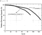
FIG. 4 is a discharge capacity graph of Example 1 and Comparative Example 1 of the present invention. -
FIG. 5 is a relative discharge capacity graph of Example 1 and Comparative Example 1 of the present invention. -
FIG. 6 is a discharge capacity graph of Example 1 and Comparative Example 2 of the present invention. -
FIG. 7 is a relative discharge capacity graph of Example 1 and Comparative Example 2 of the present invention. - Hereinafter, the present invention will be described in detail with reference to accompanying drawings so that those skilled in the art may readily implement the present invention. However, the present invention may be implemented in various different forms, and is not limited to the present specification.
- The present invention provides a negative electrode for a lithium secondary battery including a lithium metal layer; and a protective layer formed on at least one surface of the lithium metal layer, wherein the protective layer includes a conductive fabric with pores formed therein.
- Common protective layers protecting lithium metal suppress an electrochemical reaction to resolve a lithium dendrite problem, however, the present invention introduces a conductive protective layer to increase electrochemical reactivity, and thereby enhancing the electrochemical performance, and also suppresses local lithium dendrite formation on a lithium metal layer surface since lithium plating and stripping occurs in the pores formed by crossing of the warp and the weft of the conductive fabric. Such a fabric form is preferred as a protective layer due to reasons such as controlling a thickness, securing certain pores and maintaining a stable form.
- The conductive fabric of the present invention has flexibility and tension/contraction due to fabric properties, and therefore, when used as a protective layer of a lithium electrode, is capable of maintaining mechanical stability even under lithium dendrite formation.
- In order to maximize such effects, a pore size of the conductive fabric is formed to tens to millions of nano-sizes, and preferably, is from 1 µm to 10,000 µm and more preferably from 10 µm to 3,000 µm.
- Porosity, the percentage of the pores in the conductive fabric, is preferably from 5% to 50% as a percentage of the area occupied by the pore region based on 100% of the whole protective layer area. When the porosity is less than 5%, the effect of suppressing lithium dendrite formation, a goal of the present invention, may not be secured, and when the porosity is greater than 50%, an area of contact between the protective layer and the lithium metal layer relatively decreases declining battery performance.
- The conductive fabric being thinner is advantageous for a battery performance, however, lithium dendrite formation may be suppressed when the conductive fabric is formed to a certain thickness or higher. Considering the significance of improving effects obtained by such protective layer formation, the thickness is preferably from 0.01 µm to 50 µm.
- Having conductivity as a protective layer of a lithium electrode may enhance battery performance by facilitating electrochemical reactions, and therefore, the conductive fabric preferably has a sheet resistance of 0.001 ohmn/sq to 1 ohmn/sq. When the sheet resistance is greater than 1 ohmn/sq, an effect of enhancing an battery performance through conductivity, a goal of the present invention, is difficult to secure, and when the fabric has sheet resistance of less than 0.001 ohmn/sq, ions and products do not readily migrate due to quick polarization by electrochemical reactants and products, which declines battery performance.
- Preferably, as shown in
FIG. 1 , threads (10) form the warp and the weft by forming a plurality of assembled bundles in the conductive fabric, and are weaved to a base fabric. An outer surface of the thread of the base fabric may be coated with a metal material (20), and an outer surface of the metal material may be coated with a carbon material (30). - As the thread, one or more types are selected from the group consisting of polyester, polyamide, polyethylene, polyurethane, polypropylene, polyurea, cotton, wool, silk and linen, and are weaved to a base fabric.
- As the metal material uniformly coated on the weaved base fabric, one or more types selected from the group consisting of nickel (Ni), copper (Cu), aluminum (Al), gold (Au), silver (Ag), zinc (Zn) and tin (Sn) are preferred in providing conductivity as a protective layer, a goal of the present invention.
- Herein, the metal material may be coated in 30 parts by weight to 70 parts by weight and preferably in 40 parts by weight to 60 parts by weight with respect to 100 parts by weight of the base fabric. When the metal material is coated in less than 30 parts by weight, providing conductivity to the fabric is insufficient, and effects that the present invention aims to obtain are difficult to secure, and when the metal material is coated in greater than 70 parts by weight, flexibility and tension/contraction, properties of the fabric itself, decrease.
- The carbon material coated on an outer surface of the metal material may suppress non-uniform lamination of lithium dendrite, and enables a stable solid electrolyte interphase (SEI) layer to form locally in the pore by inducing a lithium dendrite reaction inside the pores. In addition, the carbon material performs a role as a binder of the threads coated with the metal material and thereby enhances adhesive strength of each of the threads. Such a carbon material is preferred as a protective layer that needs to be stable and have proper rigidity.
- As the carbon material coated on an outer surface of the metal material, one or more types may be selected from the group consisting of graphite-based such as natural graphite, artificial graphite, expanded graphite, graphene, Super-P or Super-C; active carbon-based; carbon black-based such as denka black, ketjen black, channel black, furnace black, thermal black, contact black, lamp black or acetylene black; carbon nanostructures such as carbon fiber-based, carbon nanotubes (CNT) or fullerene; and combinations thereof.
- Herein, the carbon material is coated in 20 parts by weight to 50 parts by weight and preferably in 30 parts by weight to 40 parts by weight with respect to 100 parts by weight of the base fabric. When the carbon material is coated in less than 20 parts by weight, the metal material is exposed outside leading to a problem of forming lithium dendrite on the metal material, and the carbon material being coated in greater than 50 parts by weight is not preferred since it may cause concern of blocking the pores formed in the fabric.
- The method for preparing the conductive fabric described above is not particularly limited in the present invention, but may include (S1) preparing a thread-weaved base fabric; (S2) coating a metal material on the base fabric; and (S3) coating a carbon material on the metal material.
- Hereinafter, each step will be described.
- First, a fabric having the material and the pore properties described above is prepared or purchased. Herein, the preparation is carried out through a common spinning process, and is not particularly limited in the present invention.
- Next, a metal is coated on the base fabric through a dry coating or wet coating process. Dry coating of the metal may be carried out using a PVD method such as sputtering, vacuum deposition or ion plating, or using an electro or electroless plating method. Such a method is not particularly limited in the present invention, and known methods may be used. When coating the metal through the electroless plating method, an electroless plating solution including pure water, a metal salt, a chelating agent, a reducing agent, a stabilizer and a pH modifier is prepared, and then the base fabric is immersed thereinto.
- Next, the metal material-coated base fabric is coated using a carbon material. As the carbon material, materials described above may be used, and a wet process referred to as slurry coating is used. Herein, the slurry coating is carried out by preparing a slurry coating solution including the carbon material, a binder, a solvent and a dispersant, coating the slurry coating solution on the metal material of the base fabric using various methods such as print coating, dip coating, roll coating, spin coating, flow coating or gravure coating, and then drying the result.
- As shown in
FIG. 1 , the conductive fabric prepared using the above-mentioned preparation method has a form in which a surface of each of the threads (10) forming the warp and the weft of the fabric is coated with a metal material (20), and a surface of or space between the threads is continuously coated or filled with a carbon material (30). The electroless plating method used in the present invention may preserve the original form of the thread. Accordingly, metal material coating based on the electroless plating method accomplishes a double function, that is, functions of providing metal conductivity and maintaining mechanical properties of the fabric itself. - As one example, a polyester fabric is immersed in 37% HCl (pH=1) containing 26 mM SnCl2 for 10 minutes at 25°C. Then, in order to activate the sample, the polyester fabric is immersed in 1.7 mM PdCl2, 37% HCl and 0.32 M H3BO3 at
pH 2. Next, for depositing nickel (Ni) through electroless plating, the fabric sample is immersed in 97 mM NiSO4, 27 mM trisodium citrate dihydrate, 0.34 M NH4Cl and 0.14 M NaPO2H2.H2O. Lastly, the nickel-plated fabric is washed with deionized water and dried for 20 minutes at 150°C. - In order to coat a carbon material on the prepared nickel (Ni)-coated polyester fabric, slurry is prepared by dissolving denka black and a polyurethane (PU) binder in N-methyl-2-pyrrolidinone in a weight ratio of 9:1. The slurry prepared as above is casted on the Ni-coated polyester fabric using a doctor blade technology. When the carbon layer is casted, the sample is dried in a vacuum oven at 80°C for 12 hours. A form of the denka black being laminated on the electroless-plated nickel (Ni) described above is obtained.
- In the negative electrode for a lithium secondary battery provided in the present invention, a negative electrode current collector may be additionally formed on the other side of the lithium metal layer (surface with no protective layer formation). The negative electrode current collector is not particularly limited as long as it has high conductivity without inducing chemical changes to a battery, and examples thereof may include any one metal selected from the group consisting of copper, aluminum, stainless steel, zinc, titanium, silver, palladium, nickel, iron, chromium, alloys thereof and combinations thereof. The stainless steel may have its surface treated with carbon, nickel, titanium or silver, and aluminum-cadmium alloys may be used as the alloy, and in addition thereto, baked carbon, nonconductive polymers of which surface is treated with a conductor, conductive polymers or the like may also be used. A copper thin plate is generally used as the negative electrode current collector.
- As the negative electrode current collector, those generally having a thickness range of 3 µm to 500 µm are used. When the negative electrode current collector has a thickness of less than 3 µm, a current collecting effect decreases, and the thickness being greater than 500 µm has a problem of processibility decline when assembling a cell through folding.
- As shown in
FIG. 3 , the present invention provides a lithium secondary battery including a negative electrode (100); a positive electrode (400); a separator (300) and an electrolyte (not shown) provided therebetween, wherein the negative electrode uses the conductive fabric described above as a protective layer (200). Herein, the protective layer (200) may be used on both surfaces or one surface of the negative electrode (100), and is preferably disposed on one surface adjoining the electrolyte. - In the lithium secondary battery according to the present invention, constitutions other than structures and characteristics of the negative electrode described above may be prepared through known technologies implemented by those skilled in the art, and hereinafter, specific descriptions will be provided.
- The positive electrode according to the present invention may be prepared into a positive electrode form by filming a composition including a positive electrode active material, a conductor and a binder on a positive electrode current collector.
- As the positive electrode active material, any one selected from the group consisting of LiCoO2, LiNiO2, LiMnO2, LiMn2O4, Li(NiaCobMnc) O2 (0<a<1, 0<b<1, 0<c<1, a+b+c=1), LiNi1-yCoyO2, LiCo1-yMnyO2, LiNi1-yMnyO2 (O≤≤y<1), Li (NiaCobMnc)O4 (0<a<2, 0<b<2, 0<c<2, a+b+c=2), LiMn2-zNizO4, LiMn2-zCozO4 (0<z<2), LiCoPO4 and LiFePO4, or a mixture of two or more types thereof may be used. In addition, sulfides, selenides, halides and the like may also be used in addition to such oxides. In more preferred examples, the positive electrode active material may be LiCoO2 suited for high battery performance.
- The conductor is a component for further enhancing conductivity of a positive electrode active material, and nonlimiting examples thereof may include graphite such as natural graphite or artificial graphite; carbon black such as carbon black, acetylene black, ketjen black, channel black, furnace black, lamp black and thermal black; conductive polymers such as carbon fibers or metal fibers; fluorocarbon, aluminum and metal powders such as nickel powder; conductive whiskers such as zinc oxide and potassium titanate; conductive metal oxides such as titanium oxide; conductive materials such as polyphenylene derivatives, and the like.
- The binder has functions of keeping a positive electrode active material on a positive electrode current collector, and organically linking the positive electrode active materials, and examples thereof may include polyvinylidene fluoride (PVDF), polyvinyl alcohol (PVA), carboxymethylcellulose (CMC), starch, hydroxypropylcellulose, regenerated cellulose, polyvinyl pyrrolidone, tetrafluoroethylene, polyethylene, polypropylene, an ethylene-propylene-diene polymer (EPDM), a sulfonated-EPDM, styrene-butadiene rubber, fluoro rubber, various copolymers thereof, and the like.
- The positive electrode current collector is the same as described in the negative electrode current collector, and an aluminum thin plate may be generally used as the positive electrode current collector.
- The separator according to the present invention is not particularly limited in the material and, as a material physically separating a positive electrode and a negative electrode and having electrolyte and ion penetrability, those commonly used as a separator in an electrochemical device may be used without particular limit. However, as a material that is porous, nonconductive and insulating, those having an excellent liquid electrolyte moisture-containing ability while having low resistance for ion migration of the liquid electrolyte are particularly preferred. For example, a polyolefin-based porous membrane or a non-woven fabric may be used, however, the separator is not particularly limited thereto.
- As examples of the polyolefin-based porous membrane, membranes formed with a polymer using a polyolefin-based polymer such as polyethylene such as high density polyethylene, linear low density polyethylene, low density polyethylene and ultra-high molecular weight polyethylene, polypropylene, polybutylene and polypentene alone, or formed with a polymer mixing these may be used.
- As the non-woven fabric other than the polyolefin-based non-woven fabric described above, a non-woven fabric formed with a polymer using, for example, polyphenylene oxide, polyimide, polyamide, polycarbonate, polyethylene terephthalate, polyethylene naphthalate, polybutylene terephthalate, polyphenylene sulfide, polyacetal, polyether sulfone, polyetheretherketone, polyester and the like alone, or formed with a polymer mixing these may be used, and, as a fiber form forming a porous web, such a non-woven fabric includes a spunbond or meltblown form formed with long fibers.
- The thickness of the separator is not particularly limited, but is preferably in a range of 1 µm to 100 µm, and more preferably in a range of 5 µm to 50 µm. When the separator has a thickness of less than 1 µm, mechanical properties may not be maintained, and when the thickness is greater than 100 µm, the separator functions as a resistive layer declining battery performance.
- A pore size and porosity of the separator are not particularly limited, however, the pore size is preferably from 0.1 µm to 50 µm, and the porosity is preferably from 10% to 95%. When the separator has a pore size of less than 0.1 µm or porosity of less than 10%, the separator functions as a resistive layer, and when the pore size is greater than 50 µm or the porosity is greater than 95%, mechanical properties may not be maintained.
- The electrolyte capable of being used in the present invention may be a liquid non-aqueous electrolyte, or a polymer electrolyte such as a solid electrolyte or a gel electrolyte. In the former, the non-aqueous electrolyte battery is formed as a so-called lithium ion secondary battery, and in the latter, the non-aqueous electrolyte battery is formed as a polymer electrolyte battery such as a polymer solid electrolyte battery or a polymer gel electrolyte battery. When the solid electrolyte performs a function of the separator described above, a separate separator may not be included.
- The electrolyte salt included in the non-aqueous liquid electrolyte is a lithium salt. As the lithium salt, those commonly used in liquid electrolytes for a lithium secondary battery may be used without limit. For example, an anion of the lithium salt may include any one selected from the group consisting of F-, Cl-, Br-, I-, NO3 -, N(CN)2 -, BF4 -, ClO4 -, PF6 -, (CF3)2PF4 -, (CF3)3PF3 -, (CF3)4PF2 -, (CF3)5PF-, (CF3)6P-, CF3SO3 -, CF3CF2SO3 -, (CF3SO2)2N-, (FSO2)2N-, CF3CF2 (CF3)2CO-, (CF3SO2)2CH-, (SF5)3C-, (CF3SO2)3C-, CF3(CF2) 7SO3 -, CF3CO2 -, CH3CO2 -, SCN- and (CF3CF2SO2)2N-, or two or more types thereof.
- The concentration of the lithium salt included in the non-aqueous liquid electrolyte is preferably from 0.1 mol/L to 5 mol/L and more preferably from 0.5 mol/L to 3.0 mol/L.
- As the organic solvent included in the non-aqueous liquid electrolyte, those commonly used in liquid electrolytes for a lithium secondary battery may be used without limit, and for example, ether, ester, amide, linear carbonate, cyclic carbonate and the like may be used either alone or as a mixture of two or more types.
- As the ether among the organic solvents, any one selected from the group consisting of dimethyl ether, diethyl ether, dipropyl ether, methylethyl ether, methylpropyl ether, ethylpropyl ether, ethoxyethyl ether, diethylene glycol dibutyl ether, tetraethylene glycol dimethyl ether, polyethylene glycol dimethyl ether and dioxolane, or a mixture of two or more types thereof may be used, however, the ether is not limited thereto.
- As the ester among the organic solvents, any one selected from the group consisting of methyl acetate, ethyl acetate, propyl acetate, methyl propionate, ethyl propionate, propyl propionate, γ-butyrolactone, γ-valerolactone, γ-caprolactone, σ-valerolactone and ε-caprolactone, or a mixture of two or more types thereof may be used, however, the ester is not limited thereto.
- Specific examples of the linear carbonate compound may typically include any one selected from the group consisting of dimethyl carbonate, diethyl carbonate, dipropyl carbonate, ethylmethyl carbonate, methylpropyl carbonate and ethylpropyl carbonate, or a mixture of two or more types thereof, but are not limited thereto.
- Specific examples of the cyclic carbonate compound may include any one selected from the group consisting of ethylene carbonate, propylene carbonate, 1,2-butylene carbonate, 2,3-butylene carbonate, 1,2-pentylene carbonate, 2,3-pentylene carbonate, vinylene carbonate, vinyl ethylene carbonate and halides thereof, or a mixture of two or more types thereof. Examples of the halides thereof may include fluoroethylene carbonate and the like, but are not limited thereto.
- The non-aqueous liquid electrolyte may be injected at a proper stage in an electrochemical device manufacturing process depending on manufacturing process and required properties of a final product. In other words, the non-aqueous liquid electrolyte may be injected at a stage prior to assembling an electrochemical device or at a final stage of electrochemical device assembly.
- The lithium secondary battery according to the present invention may go through lamination (stack) and folding processes of a separator and an electrode in addition to winding, a general process. In addition, the battery case may be a cylinder-type, a square-type, a pouch-type, a coin-type or the like.
- As described above, the lithium secondary battery according to the present invention stably exhibits excellent cycle performance and electrochemical performance, and therefore, is useful in the fields of portable devices such as mobile phones, notebook computers or digital cameras, electric vehicles such as hybrid electric vehicles (HEV), and the like.
- According to another embodiment of the present invention, there is provided a battery module including the lithium secondary battery as a unit cell, and a battery pack including the same. The battery module or the battery pack may be used as a power supply of any one or more medium to large-sized devices such as power tools; electric vehicles including electric vehicles (EV), hybrid electric vehicles (HEV) and plug-in hybrid electric vehicles (PHEV); or systems for power storage.
- Hereinafter, the present invention will be described in detail with reference to examples in order to specifically describe the present invention. However, the examples according to the present invention may be modified to various different forms, and the scope of the present invention is not construed as being limited to the examples described below. The examples of the present invention are provided in order to more fully describe the present invention for those having average knowledge in the art.
- After preparing as in the following Table 1, a coin cell was assembled in order of body/cathode/separator/conductive fabric/anode/spacer/Ni foam/spring/cap. Herein, as the conductive fabric, a polyester thread was coated with nickel (Ni) as a metal material, and coated with a mixture mixing an active material (LCO), a conductor (CNT-based) and a binder (PVDF-based) as a carbon material, and the conductive fabric had sheet resistance of 0.08 ohmn/sq, a thickness of 32 µm to 35 µm, a pore size of 7 µm to 28 µm and porosity of approximately 15%.
[Table 1] Cathode LiCoO2, 20 um Al Foil Separator PE Anode 20 um Li metal, 10 um Cu Foil Electrolyte 80 uL, Carbonate-Based Liquid Electrolyte - A coin cell was assembled using the same constitutions as in Example 1 except the conductive fabric.
- A coin cell was assembled using the same constitutions as in Example 1 except a nonconductive fabric instead of the conductive fabric.
- Herein, as the nonconductive fabric, a polyester thread was used, which had sheet resistance of 0.3 ohmn/sq, a thickness of 29 µm to 33 µm, a pore size of 10 µm to 25 µm and porosity of approximately 15%.
- The coin cell lithium secondary batteries of Example 1 and Comparative Examples 1 and 2 were charged and discharged under the following condition.
- Formation: Charge 0.2 C / Discharge 0.2 C (3 times)
- Cycle: Charge 0.3 C / Discharge 0.5 C (80 times or more)
-
FIG. 4 andFIG. 6 show data with cycle as the x axis and discharge capacity as the y axis. As shown inFIG. 4 , the electrochemical performance was enhanced when using the conductive protective layer of Example 1. This is due to the fact that initial discharge capacity appears to be larger compared to Comparative Example 1 when using the conductive fabric. - In addition, as shown in
FIG. 6 , it was seen that the electrochemical performance was enhanced when using the conductive protective layer of Example 1 compared to Comparative Example 2 using a nonconductive fabric. This is due to the fact that electrical resistance decreases compared to Comparative Example 2 using a nonconductive fabric due to conductivity. -
FIG. 5 andFIG. 7 are graphs showing relative discharge capacity obtained by converting initial discharge capacity to 100. ThroughFIG. 5 , retention of discharge capacity was identified as the cycle increased, and it was seen that capacity retention was more favorable when using the conductive fabric of Example 1 as a protective layer compared to Comparative Example 1. In other words, enhancement in the cycle performance was identified. This is due to the fact that stable solid electrolyte interphase (SEI) layers are formed locally on lithium metal since a carbon material is coated on an outermost layer by the conductive fabric enabling a reaction in the pores. - Likewise, as shown in
FIG. 7 , it was seen that a capacity retention property was improved when using the conductive protective layer of Example 1 compared to Comparative Example 2 using a nonconductive fabric. -
- 10.
- Thread
- 20.
- Metal Material
- 30.
- Carbon Material
- 100.
- Negative Electrode
- 200.
- Protective Layer
- 300.
- Separator
- 400.
- Positive Electrode
Claims (12)
- A negative electrode for a lithium secondary battery comprising:a lithium metal layer; anda protective layer formed on at least one surface of the lithium metal layer,wherein the protective layer comprises a conductive fabric with pores formed therein.
- The negative electrode for a lithium secondary battery of Claim 1, wherein the conductive fabric is a conductive fabric consecutively coating a metal material and a carbon material on a thread-weaved base fabric.
- The negative electrode for a lithium secondary battery of Claim 1, wherein the conductive fabric has a pore size of 1 µm to 10,000 µm.
- The negative electrode for a lithium secondary battery of Claim 1, wherein the conductive fabric has a porosity of 5% to 50%.
- The negative electrode for a lithium secondary battery of Claim 1, wherein the conductive fabric has a thickness of 0.01 µm to 50 µm.
- The negative electrode for a lithium secondary battery of Claim 1, wherein the conductive fabric has a sheet resistance of 0.001 ohmn/sq to 1 ohmn/sq.
- The negative electrode for a lithium secondary battery of Claim 2, wherein the thread is one or more types selected from the group consisting of polyester, polyamide, polyethylene, polyurethane, polypropylene, polyurea, cotton, wool, silk and linen.
- The negative electrode for a lithium secondary battery of Claim 2, wherein the metal material is one or more types selected from the group consisting of nickel (Ni), copper (Cu), aluminum (Al), gold (Au), silver (Ag), zinc (Zn) and tin (Sn).
- The negative electrode for a lithium secondary battery of Claim 2, wherein the metal material is coated in 30 parts by weight to 70 parts by weight with respect to 100 parts by weight of the base fabric.
- The negative electrode for a lithium secondary battery of Claim 2, wherein the carbon material is one or more types selected from the group consisting of graphite-based such as natural graphite, artificial graphite, expanded graphite, graphene, Super-P or Super-C; active carbon-based; carbon black-based such as denka black, ketjen black, channel black, furnace black, thermal black, contact black, lamp black or acetylene black; carbon nanostructures such as carbon fiber-based, carbon nanotubes (CNT) or fullerene; and combinations thereof.
- The negative electrode for a lithium secondary battery of Claim 2, wherein the carbon material is coated in 20 parts by weight to 50 parts by weight with respect to 100 parts by weight of the base fabric.
- A lithium secondary battery comprising:a negative electrode;a positive electrode; andan electrolyte provided therebetween,wherein the negative electrode is the negative electrode of any one of Claims 1 to 11.
Applications Claiming Priority (3)
| Application Number | Priority Date | Filing Date | Title |
|---|---|---|---|
| KR20160126910 | 2016-09-30 | ||
| KR1020170124054A KR102328253B1 (en) | 2016-09-30 | 2017-09-26 | Anode with buffer layer made by conductive textile, lithium secondary battery containing the same |
| PCT/KR2017/010716 WO2018062844A2 (en) | 2016-09-30 | 2017-09-27 | Lithium secondary battery negative electrode including protection layer made of conductive fabric, and lithium secondary battery including same |
Publications (3)
| Publication Number | Publication Date |
|---|---|
| EP3509138A2 true EP3509138A2 (en) | 2019-07-10 |
| EP3509138A4 EP3509138A4 (en) | 2019-10-23 |
| EP3509138B1 EP3509138B1 (en) | 2020-07-08 |
Family
ID=61978122
Family Applications (1)
| Application Number | Title | Priority Date | Filing Date |
|---|---|---|---|
| EP17856730.1A Active EP3509138B1 (en) | 2016-09-30 | 2017-09-27 | Lithium secondary battery negative electrode including protection layer made of conductive fabric, and lithium secondary battery including same |
Country Status (5)
| Country | Link |
|---|---|
| US (1) | US11302910B2 (en) |
| EP (1) | EP3509138B1 (en) |
| JP (1) | JP6775849B2 (en) |
| KR (1) | KR102328253B1 (en) |
| CN (1) | CN109792044B (en) |
Cited By (4)
| Publication number | Priority date | Publication date | Assignee | Title |
|---|---|---|---|---|
| US11870078B2 (en) | 2018-10-30 | 2024-01-09 | Lg Energy Solution, Ltd. | Lithium electrode and lithium secondary battery comprising same |
| US11978852B2 (en) | 2018-10-31 | 2024-05-07 | Lg Energy Solution, Ltd. | Lithium electrode and lithium secondary battery comprising same |
| US12191498B2 (en) | 2018-10-31 | 2025-01-07 | Lg Energy Solution, Ltd. | Lithium secondary battery |
| US12355060B2 (en) | 2018-09-20 | 2025-07-08 | Lg Energy Solution, Ltd. | Anode for lithium secondary battery and lithium secondary battery comprising the same |
Families Citing this family (20)
| Publication number | Priority date | Publication date | Assignee | Title |
|---|---|---|---|---|
| KR102368088B1 (en) * | 2017-05-19 | 2022-02-24 | 삼성에스디아이 주식회사 | lithium secondary battery |
| US10873088B2 (en) * | 2018-06-25 | 2020-12-22 | Global Graphene Group, Inc. | Lithium-selenium battery containing an electrode-protecting layer and method of improving cycle-life |
| CN109378476B (en) * | 2018-09-27 | 2021-07-02 | 苏州大学 | Method for preparing lithium electrode protective layer using self-assembled RGO film |
| WO2020091426A1 (en) | 2018-10-30 | 2020-05-07 | 주식회사 엘지화학 | Lithium electrode and lithium secondary battery comprising same |
| WO2020091479A1 (en) | 2018-10-31 | 2020-05-07 | 주식회사 엘지화학 | Lithium electrode and lithium secondary battery comprising same |
| JP7127209B2 (en) | 2018-12-03 | 2022-08-29 | エルジー エナジー ソリューション リミテッド | Flexible electrode, secondary battery containing same, and flexible secondary battery |
| CN111326736B (en) * | 2018-12-17 | 2021-05-28 | 宁德时代新能源科技股份有限公司 | Lithium metal battery |
| KR102751122B1 (en) * | 2019-05-09 | 2025-01-06 | 주식회사 엘지에너지솔루션 | A method for manufacturing an all solid state lithium secondary battery |
| KR102522025B1 (en) | 2019-05-14 | 2023-04-14 | 주식회사 엘지에너지솔루션 | Lithium secondary battery |
| CN110323438B (en) * | 2019-07-11 | 2022-04-05 | 宁波大学 | A silk fibroin carbonized material that inhibits lithium dendrite growth |
| KR20210070822A (en) * | 2019-12-05 | 2021-06-15 | 한국자동차연구원 | Anode electrode for lithium metal secondary battery and methods of fabricating the same |
| KR102244179B1 (en) * | 2020-04-21 | 2021-04-26 | 서울과학기술대학교 산학협력단 | Redox flow cell comprising cellulose |
| CN111647345B (en) * | 2020-04-21 | 2022-03-18 | 万向一二三股份公司 | Lithium ion battery negative electrode polymer protective coating and preparation method and application thereof |
| EP4050678A4 (en) * | 2020-11-02 | 2023-04-19 | LG Energy Solution, Ltd. | NEGATIVE ELECTRODE FOR LITHIUM METAL BATTERY, METHOD FOR MANUFACTURING THEREOF, AND LITHIUM METAL BATTERY COMPRISING IT |
| US12374678B2 (en) * | 2020-12-03 | 2025-07-29 | Elevated Materials Us Llc | Lithium metal surface modification using carbonate passivation |
| JP7702743B2 (en) * | 2021-02-08 | 2025-07-04 | TeraWatt Technology株式会社 | Lithium secondary battery |
| WO2022255672A1 (en) * | 2021-06-02 | 2022-12-08 | 주식회사 엘지에너지솔루션 | Lithium electrode and lithium secondary battery comprising same |
| KR102794878B1 (en) * | 2022-04-04 | 2025-04-10 | 단국대학교 천안캠퍼스 산학협력단 | Textile composite for intermediate layer of lithium metal secondary battery, preparation method thereof, and lithium metal secondary battery comprising the same |
| EP4693433A1 (en) * | 2023-03-26 | 2026-02-11 | Samsung Sdi Co., Ltd. | Lithium metal battery, and method for manufacturing lithium metal battery anode included therein |
| KR102799334B1 (en) * | 2023-11-30 | 2025-04-24 | 주식회사 시리에너지 | Mesh-structured lithium electrode and lithium secondary battery including thereof |
Family Cites Families (34)
| Publication number | Priority date | Publication date | Assignee | Title |
|---|---|---|---|---|
| DE3603373A1 (en) * | 1986-02-05 | 1987-08-06 | Basf Ag | METHOD FOR THE ELECTROCHEMICAL COATING OF CARBON FIBERS |
| JPS63150867A (en) | 1986-12-16 | 1988-06-23 | Sanyo Electric Co Ltd | Nonaqueous secondary cell |
| TW393797B (en) | 1996-09-26 | 2000-06-11 | Toray Industries | An electrode for a battery and a battery using it |
| KR19990055229A (en) | 1997-12-27 | 1999-07-15 | 전주범 | Lithium Battery and Manufacturing Method Thereof |
| US7247408B2 (en) | 1999-11-23 | 2007-07-24 | Sion Power Corporation | Lithium anodes for electrochemical cells |
| JP5106732B2 (en) * | 1999-11-23 | 2012-12-26 | シオン・パワー・コーポレーション | Lithium negative electrode for electrochemical cells |
| JP2004022332A (en) | 2002-06-17 | 2004-01-22 | Kawasaki Heavy Ind Ltd | Electrode using fibrous hydrogen storage alloy, battery and electric double layer capacitor using fibrous hydrogen storage alloy |
| JP4914059B2 (en) | 2005-01-14 | 2012-04-11 | 住友電気工業株式会社 | Current collector, battery electrode substrate, and manufacturing method thereof |
| JP4842633B2 (en) * | 2005-12-22 | 2011-12-21 | 富士重工業株式会社 | Method for producing lithium metal foil for battery or capacitor |
| WO2007111901A2 (en) | 2006-03-22 | 2007-10-04 | Sion Power Corporation | Electrode protection in both aqueous and non-aqueous electrochemical cells, including rechargeable lithium batteries |
| KR101196798B1 (en) | 2008-02-25 | 2012-11-05 | 주식회사 엘지화학 | ANODE COATED WITH LiF COMPOUNDS AND METHOD FOR PREPARATION THEREOF AND LITHIUM SECONDARY BATTERY COMPRISING THE ANODE |
| JP2010086737A (en) * | 2008-09-30 | 2010-04-15 | Panasonic Corp | Nonaqueous electrolyte battery |
| DE102010062006A1 (en) | 2010-11-26 | 2012-05-31 | Robert Bosch Gmbh | Nanofibers comprising anode material for a lithium-ion cell |
| CN102142532B (en) | 2011-01-27 | 2013-10-02 | 上海电气钠硫储能技术有限公司 | Stereo braiding-based carbon sulfur composite electrode for sodium sulfur battery |
| KR101417268B1 (en) | 2012-05-02 | 2014-07-08 | 현대자동차주식회사 | Lithium electrode for lithium battery and method for manufacturing the same |
| US9812706B2 (en) * | 2012-12-28 | 2017-11-07 | Industrial Technology Research Institute | Protected active metal electrode and device with the electrode |
| KR101477782B1 (en) * | 2013-04-11 | 2014-12-31 | 한국과학기술원 | Electrode for lithum-sulphur secondary battery using composite of polymer nanofiber, aluminum thin film, carbon nanotube and sulphur, and fabricating method thereof |
| KR101624303B1 (en) | 2013-04-26 | 2016-05-27 | 한국과학기술원 | Electrode of polymer nanofiber coated with aluminum thin film and manufacturing method thereof |
| CN204441379U (en) | 2013-05-07 | 2015-07-01 | 株式会社Lg化学 | Electrode for secondary battery, and secondary battery and cable-type secondary battery comprising same |
| CN105794018B (en) | 2013-09-02 | 2020-07-17 | 日本戈尔有限公司 | Protective film, spacer using the same, and rechargeable battery |
| KR101621410B1 (en) | 2013-09-11 | 2016-05-16 | 주식회사 엘지화학 | Lithium electrode and lithium secondary battery including the same |
| DE102013222784A1 (en) | 2013-11-08 | 2015-05-13 | Robert Bosch Gmbh | Electrochemical cell and process for its preparation |
| CN106170878A (en) | 2014-02-19 | 2016-11-30 | 密执安州立大学董事会 | Dendrite-suppressing ionic conductors from aramid nanofibers enduring extreme battery conditions |
| KR101551472B1 (en) | 2014-06-05 | 2015-09-09 | 한국과학기술원 | Yarn based flexible lithium-ion batteries of twisting yarn structured composite electrode consisting of nanofibers and active materials, and fabrication method thereof |
| TWI563716B (en) | 2014-07-16 | 2016-12-21 | Prologium Technology Co Ltd | Anode electrode |
| KR101750327B1 (en) | 2014-09-19 | 2017-06-23 | 주식회사 엘지화학 | A Electrode Assembly for Secondary Battery and A Manufacturing Method for the Same |
| KR101811495B1 (en) * | 2014-09-19 | 2017-12-20 | 주식회사 엘지화학 | Negative electrode for rechargeable lithium battery and rechargeable lithium battery comprising same |
| KR101622354B1 (en) | 2014-10-14 | 2016-05-18 | 울산과학기술원 | Methode of manufacturing three-dimensional porous-structured electrode, and electrochemical device having the electrode |
| KR101632797B1 (en) | 2014-10-21 | 2016-06-23 | 한국과학기술원 | Li-air battery using current collector-catalysts monolithic 3 dimensional nanofiber network for Li-air battery and manufacturing method thereof |
| KR101781680B1 (en) | 2014-12-02 | 2017-09-25 | 한양대학교 산학협력단 | flexible and stretchable piezoelectronic fiber and fabrication method thereof |
| EP3278383A4 (en) * | 2015-03-30 | 2018-09-05 | Solidenergy Systems | Composite coating systems and methods for lithium metal anodes in battery applications |
| US9780379B2 (en) * | 2015-05-21 | 2017-10-03 | Nanotek Instruments, Inc. | Alkali metal secondary battery containing a carbon matrix- or carbon matrix composite-based dendrite intercepting layer |
| CN105792394A (en) | 2016-03-15 | 2016-07-20 | 东华大学 | Fibriform tensile heater and manufacture method thereof |
| US10586661B2 (en) * | 2016-08-08 | 2020-03-10 | Global Graphene Group, Inc. | Process for producing graphene oxide-bonded metal foil thin film current collector for a battery or supercapacitor |
-
2017
- 2017-09-26 KR KR1020170124054A patent/KR102328253B1/en active Active
- 2017-09-27 EP EP17856730.1A patent/EP3509138B1/en active Active
- 2017-09-27 US US16/328,625 patent/US11302910B2/en active Active
- 2017-09-27 JP JP2019512629A patent/JP6775849B2/en active Active
- 2017-09-27 CN CN201780059241.5A patent/CN109792044B/en active Active
Cited By (4)
| Publication number | Priority date | Publication date | Assignee | Title |
|---|---|---|---|---|
| US12355060B2 (en) | 2018-09-20 | 2025-07-08 | Lg Energy Solution, Ltd. | Anode for lithium secondary battery and lithium secondary battery comprising the same |
| US11870078B2 (en) | 2018-10-30 | 2024-01-09 | Lg Energy Solution, Ltd. | Lithium electrode and lithium secondary battery comprising same |
| US11978852B2 (en) | 2018-10-31 | 2024-05-07 | Lg Energy Solution, Ltd. | Lithium electrode and lithium secondary battery comprising same |
| US12191498B2 (en) | 2018-10-31 | 2025-01-07 | Lg Energy Solution, Ltd. | Lithium secondary battery |
Also Published As
| Publication number | Publication date |
|---|---|
| EP3509138B1 (en) | 2020-07-08 |
| CN109792044A (en) | 2019-05-21 |
| US20200235385A1 (en) | 2020-07-23 |
| JP6775849B2 (en) | 2020-10-28 |
| KR20180036564A (en) | 2018-04-09 |
| JP2019526904A (en) | 2019-09-19 |
| EP3509138A4 (en) | 2019-10-23 |
| CN109792044B (en) | 2022-05-13 |
| US11302910B2 (en) | 2022-04-12 |
| KR102328253B1 (en) | 2021-11-18 |
Similar Documents
| Publication | Publication Date | Title |
|---|---|---|
| EP3509138B1 (en) | Lithium secondary battery negative electrode including protection layer made of conductive fabric, and lithium secondary battery including same | |
| EP3429014B1 (en) | Lithium secondary battery having lithium metal formed on cathode and manufacturing method therefor | |
| EP3386008B1 (en) | Anode having double-protection layer formed thereon for lithium secondary battery, and lithium secondary battery comprising same | |
| US9711798B2 (en) | Lithium electrode and lithium secondary battery comprising the same | |
| US10686193B2 (en) | Negative electrode comprising mesh-type current collector, lithium secondary battery comprising the same, and manufacturing method thereof | |
| US9673443B2 (en) | Lithium electrode and lithium secondary battery comprising the same | |
| EP3273515A2 (en) | Electrode with perforated current collector and lithium secondary battery including the same | |
| JP6872095B2 (en) | Negative electrode including electrode protection layer and lithium secondary battery to which this is applied | |
| EP3471193A1 (en) | Lithium secondary battery comprising cathode active material for synthesizing lithium cobalt oxide, and manufacturing method therefor | |
| KR20180127189A (en) | Method for preparing negative electrode for lithium secondary battery | |
| WO2018062844A2 (en) | Lithium secondary battery negative electrode including protection layer made of conductive fabric, and lithium secondary battery including same | |
| KR20180011715A (en) | Anode Comprising Mesh Type Current Collector, Lithium Secondary Battery Comprising the Same and Manufacturing Method thereof |
Legal Events
| Date | Code | Title | Description |
|---|---|---|---|
| STAA | Information on the status of an ep patent application or granted ep patent |
Free format text: STATUS: THE INTERNATIONAL PUBLICATION HAS BEEN MADE |
|
| PUAI | Public reference made under article 153(3) epc to a published international application that has entered the european phase |
Free format text: ORIGINAL CODE: 0009012 |
|
| STAA | Information on the status of an ep patent application or granted ep patent |
Free format text: STATUS: REQUEST FOR EXAMINATION WAS MADE |
|
| 17P | Request for examination filed |
Effective date: 20190403 |
|
| AK | Designated contracting states |
Kind code of ref document: A2 Designated state(s): AL AT BE BG CH CY CZ DE DK EE ES FI FR GB GR HR HU IE IS IT LI LT LU LV MC MK MT NL NO PL PT RO RS SE SI SK SM TR |
|
| AX | Request for extension of the european patent |
Extension state: BA ME |
|
| REG | Reference to a national code |
Ref country code: DE Ref legal event code: R079 Ref document number: 602017019605 Country of ref document: DE Free format text: PREVIOUS MAIN CLASS: H01M0004134000 Ipc: H01M0002160000 |
|
| A4 | Supplementary search report drawn up and despatched |
Effective date: 20190924 |
|
| RIC1 | Information provided on ipc code assigned before grant |
Ipc: H01M 4/74 20060101ALI20190918BHEP Ipc: H01M 2/16 20060101AFI20190918BHEP Ipc: H01M 4/66 20060101ALI20190918BHEP |
|
| DAV | Request for validation of the european patent (deleted) | ||
| DAX | Request for extension of the european patent (deleted) | ||
| GRAP | Despatch of communication of intention to grant a patent |
Free format text: ORIGINAL CODE: EPIDOSNIGR1 |
|
| STAA | Information on the status of an ep patent application or granted ep patent |
Free format text: STATUS: GRANT OF PATENT IS INTENDED |
|
| INTG | Intention to grant announced |
Effective date: 20200320 |
|
| GRAS | Grant fee paid |
Free format text: ORIGINAL CODE: EPIDOSNIGR3 |
|
| GRAA | (expected) grant |
Free format text: ORIGINAL CODE: 0009210 |
|
| STAA | Information on the status of an ep patent application or granted ep patent |
Free format text: STATUS: THE PATENT HAS BEEN GRANTED |
|
| AK | Designated contracting states |
Kind code of ref document: B1 Designated state(s): AL AT BE BG CH CY CZ DE DK EE ES FI FR GB GR HR HU IE IS IT LI LT LU LV MC MK MT NL NO PL PT RO RS SE SI SK SM TR |
|
| REG | Reference to a national code |
Ref country code: CH Ref legal event code: EP Ref country code: AT Ref legal event code: REF Ref document number: 1289421 Country of ref document: AT Kind code of ref document: T Effective date: 20200715 |
|
| REG | Reference to a national code |
Ref country code: DE Ref legal event code: R096 Ref document number: 602017019605 Country of ref document: DE |
|
| REG | Reference to a national code |
Ref country code: IE Ref legal event code: FG4D |
|
| REG | Reference to a national code |
Ref country code: LT Ref legal event code: MG4D |
|
| REG | Reference to a national code |
Ref country code: DE Ref legal event code: R079 Ref document number: 602017019605 Country of ref document: DE Free format text: PREVIOUS MAIN CLASS: H01M0002160000 Ipc: H01M0050409000 |
|
| REG | Reference to a national code |
Ref country code: AT Ref legal event code: MK05 Ref document number: 1289421 Country of ref document: AT Kind code of ref document: T Effective date: 20200708 |
|
| REG | Reference to a national code |
Ref country code: NL Ref legal event code: MP Effective date: 20200708 |
|
| PG25 | Lapsed in a contracting state [announced via postgrant information from national office to epo] |
Ref country code: FI Free format text: LAPSE BECAUSE OF FAILURE TO SUBMIT A TRANSLATION OF THE DESCRIPTION OR TO PAY THE FEE WITHIN THE PRESCRIBED TIME-LIMIT Effective date: 20200708 Ref country code: LT Free format text: LAPSE BECAUSE OF FAILURE TO SUBMIT A TRANSLATION OF THE DESCRIPTION OR TO PAY THE FEE WITHIN THE PRESCRIBED TIME-LIMIT Effective date: 20200708 Ref country code: ES Free format text: LAPSE BECAUSE OF FAILURE TO SUBMIT A TRANSLATION OF THE DESCRIPTION OR TO PAY THE FEE WITHIN THE PRESCRIBED TIME-LIMIT Effective date: 20200708 Ref country code: HR Free format text: LAPSE BECAUSE OF FAILURE TO SUBMIT A TRANSLATION OF THE DESCRIPTION OR TO PAY THE FEE WITHIN THE PRESCRIBED TIME-LIMIT Effective date: 20200708 Ref country code: BG Free format text: LAPSE BECAUSE OF FAILURE TO SUBMIT A TRANSLATION OF THE DESCRIPTION OR TO PAY THE FEE WITHIN THE PRESCRIBED TIME-LIMIT Effective date: 20201008 Ref country code: GR Free format text: LAPSE BECAUSE OF FAILURE TO SUBMIT A TRANSLATION OF THE DESCRIPTION OR TO PAY THE FEE WITHIN THE PRESCRIBED TIME-LIMIT Effective date: 20201009 Ref country code: AT Free format text: LAPSE BECAUSE OF FAILURE TO SUBMIT A TRANSLATION OF THE DESCRIPTION OR TO PAY THE FEE WITHIN THE PRESCRIBED TIME-LIMIT Effective date: 20200708 Ref country code: PT Free format text: LAPSE BECAUSE OF FAILURE TO SUBMIT A TRANSLATION OF THE DESCRIPTION OR TO PAY THE FEE WITHIN THE PRESCRIBED TIME-LIMIT Effective date: 20201109 Ref country code: SE Free format text: LAPSE BECAUSE OF FAILURE TO SUBMIT A TRANSLATION OF THE DESCRIPTION OR TO PAY THE FEE WITHIN THE PRESCRIBED TIME-LIMIT Effective date: 20200708 Ref country code: NO Free format text: LAPSE BECAUSE OF FAILURE TO SUBMIT A TRANSLATION OF THE DESCRIPTION OR TO PAY THE FEE WITHIN THE PRESCRIBED TIME-LIMIT Effective date: 20201008 |
|
| PG25 | Lapsed in a contracting state [announced via postgrant information from national office to epo] |
Ref country code: RS Free format text: LAPSE BECAUSE OF FAILURE TO SUBMIT A TRANSLATION OF THE DESCRIPTION OR TO PAY THE FEE WITHIN THE PRESCRIBED TIME-LIMIT Effective date: 20200708 Ref country code: LV Free format text: LAPSE BECAUSE OF FAILURE TO SUBMIT A TRANSLATION OF THE DESCRIPTION OR TO PAY THE FEE WITHIN THE PRESCRIBED TIME-LIMIT Effective date: 20200708 Ref country code: PL Free format text: LAPSE BECAUSE OF FAILURE TO SUBMIT A TRANSLATION OF THE DESCRIPTION OR TO PAY THE FEE WITHIN THE PRESCRIBED TIME-LIMIT Effective date: 20200708 Ref country code: IS Free format text: LAPSE BECAUSE OF FAILURE TO SUBMIT A TRANSLATION OF THE DESCRIPTION OR TO PAY THE FEE WITHIN THE PRESCRIBED TIME-LIMIT Effective date: 20201108 |
|
| PG25 | Lapsed in a contracting state [announced via postgrant information from national office to epo] |
Ref country code: NL Free format text: LAPSE BECAUSE OF FAILURE TO SUBMIT A TRANSLATION OF THE DESCRIPTION OR TO PAY THE FEE WITHIN THE PRESCRIBED TIME-LIMIT Effective date: 20200708 |
|
| REG | Reference to a national code |
Ref country code: DE Ref legal event code: R097 Ref document number: 602017019605 Country of ref document: DE |
|
| PG25 | Lapsed in a contracting state [announced via postgrant information from national office to epo] |
Ref country code: CZ Free format text: LAPSE BECAUSE OF FAILURE TO SUBMIT A TRANSLATION OF THE DESCRIPTION OR TO PAY THE FEE WITHIN THE PRESCRIBED TIME-LIMIT Effective date: 20200708 Ref country code: DK Free format text: LAPSE BECAUSE OF FAILURE TO SUBMIT A TRANSLATION OF THE DESCRIPTION OR TO PAY THE FEE WITHIN THE PRESCRIBED TIME-LIMIT Effective date: 20200708 Ref country code: RO Free format text: LAPSE BECAUSE OF FAILURE TO SUBMIT A TRANSLATION OF THE DESCRIPTION OR TO PAY THE FEE WITHIN THE PRESCRIBED TIME-LIMIT Effective date: 20200708 Ref country code: EE Free format text: LAPSE BECAUSE OF FAILURE TO SUBMIT A TRANSLATION OF THE DESCRIPTION OR TO PAY THE FEE WITHIN THE PRESCRIBED TIME-LIMIT Effective date: 20200708 Ref country code: SM Free format text: LAPSE BECAUSE OF FAILURE TO SUBMIT A TRANSLATION OF THE DESCRIPTION OR TO PAY THE FEE WITHIN THE PRESCRIBED TIME-LIMIT Effective date: 20200708 Ref country code: IT Free format text: LAPSE BECAUSE OF FAILURE TO SUBMIT A TRANSLATION OF THE DESCRIPTION OR TO PAY THE FEE WITHIN THE PRESCRIBED TIME-LIMIT Effective date: 20200708 |
|
| REG | Reference to a national code |
Ref country code: CH Ref legal event code: PL |
|
| PLBE | No opposition filed within time limit |
Free format text: ORIGINAL CODE: 0009261 |
|
| STAA | Information on the status of an ep patent application or granted ep patent |
Free format text: STATUS: NO OPPOSITION FILED WITHIN TIME LIMIT |
|
| PG25 | Lapsed in a contracting state [announced via postgrant information from national office to epo] |
Ref country code: AL Free format text: LAPSE BECAUSE OF FAILURE TO SUBMIT A TRANSLATION OF THE DESCRIPTION OR TO PAY THE FEE WITHIN THE PRESCRIBED TIME-LIMIT Effective date: 20200708 |
|
| 26N | No opposition filed |
Effective date: 20210409 |
|
| REG | Reference to a national code |
Ref country code: BE Ref legal event code: MM Effective date: 20200930 |
|
| PG25 | Lapsed in a contracting state [announced via postgrant information from national office to epo] |
Ref country code: SK Free format text: LAPSE BECAUSE OF FAILURE TO SUBMIT A TRANSLATION OF THE DESCRIPTION OR TO PAY THE FEE WITHIN THE PRESCRIBED TIME-LIMIT Effective date: 20200708 Ref country code: LU Free format text: LAPSE BECAUSE OF NON-PAYMENT OF DUE FEES Effective date: 20200927 |
|
| PG25 | Lapsed in a contracting state [announced via postgrant information from national office to epo] |
Ref country code: IE Free format text: LAPSE BECAUSE OF NON-PAYMENT OF DUE FEES Effective date: 20200927 Ref country code: LI Free format text: LAPSE BECAUSE OF NON-PAYMENT OF DUE FEES Effective date: 20200930 Ref country code: SI Free format text: LAPSE BECAUSE OF FAILURE TO SUBMIT A TRANSLATION OF THE DESCRIPTION OR TO PAY THE FEE WITHIN THE PRESCRIBED TIME-LIMIT Effective date: 20200708 Ref country code: CH Free format text: LAPSE BECAUSE OF NON-PAYMENT OF DUE FEES Effective date: 20200930 Ref country code: BE Free format text: LAPSE BECAUSE OF NON-PAYMENT OF DUE FEES Effective date: 20200930 |
|
| PG25 | Lapsed in a contracting state [announced via postgrant information from national office to epo] |
Ref country code: TR Free format text: LAPSE BECAUSE OF FAILURE TO SUBMIT A TRANSLATION OF THE DESCRIPTION OR TO PAY THE FEE WITHIN THE PRESCRIBED TIME-LIMIT Effective date: 20200708 Ref country code: MT Free format text: LAPSE BECAUSE OF FAILURE TO SUBMIT A TRANSLATION OF THE DESCRIPTION OR TO PAY THE FEE WITHIN THE PRESCRIBED TIME-LIMIT Effective date: 20200708 Ref country code: CY Free format text: LAPSE BECAUSE OF FAILURE TO SUBMIT A TRANSLATION OF THE DESCRIPTION OR TO PAY THE FEE WITHIN THE PRESCRIBED TIME-LIMIT Effective date: 20200708 |
|
| PG25 | Lapsed in a contracting state [announced via postgrant information from national office to epo] |
Ref country code: MK Free format text: LAPSE BECAUSE OF FAILURE TO SUBMIT A TRANSLATION OF THE DESCRIPTION OR TO PAY THE FEE WITHIN THE PRESCRIBED TIME-LIMIT Effective date: 20200708 Ref country code: MC Free format text: LAPSE BECAUSE OF FAILURE TO SUBMIT A TRANSLATION OF THE DESCRIPTION OR TO PAY THE FEE WITHIN THE PRESCRIBED TIME-LIMIT Effective date: 20200708 |
|
| REG | Reference to a national code |
Ref country code: DE Ref legal event code: R081 Ref document number: 602017019605 Country of ref document: DE Owner name: LG ENERGY SOLUTION, LTD., KR Free format text: FORMER OWNER: LG CHEM, LTD., SEOUL, KR |
|
| P01 | Opt-out of the competence of the unified patent court (upc) registered |
Effective date: 20230408 |
|
| REG | Reference to a national code |
Ref country code: GB Ref legal event code: 732E Free format text: REGISTERED BETWEEN 20230824 AND 20230831 |
|
| PGFP | Annual fee paid to national office [announced via postgrant information from national office to epo] |
Ref country code: DE Payment date: 20250820 Year of fee payment: 9 |
|
| PGFP | Annual fee paid to national office [announced via postgrant information from national office to epo] |
Ref country code: GB Payment date: 20250820 Year of fee payment: 9 |
|
| PGFP | Annual fee paid to national office [announced via postgrant information from national office to epo] |
Ref country code: FR Payment date: 20250821 Year of fee payment: 9 |