EP3509126B1 - Prismatic secondary battery - Google Patents
Prismatic secondary battery Download PDFInfo
- Publication number
- EP3509126B1 EP3509126B1 EP17845938.4A EP17845938A EP3509126B1 EP 3509126 B1 EP3509126 B1 EP 3509126B1 EP 17845938 A EP17845938 A EP 17845938A EP 3509126 B1 EP3509126 B1 EP 3509126B1
- Authority
- EP
- European Patent Office
- Prior art keywords
- current collector
- collector plate
- hole
- lid
- negative electrode
- Prior art date
- Legal status (The legal status is an assumption and is not a legal conclusion. Google has not performed a legal analysis and makes no representation as to the accuracy of the status listed.)
- Active
Links
Images




Classifications
-
- H—ELECTRICITY
- H01—ELECTRIC ELEMENTS
- H01M—PROCESSES OR MEANS, e.g. BATTERIES, FOR THE DIRECT CONVERSION OF CHEMICAL ENERGY INTO ELECTRICAL ENERGY
- H01M50/00—Constructional details or processes of manufacture of the non-active parts of electrochemical cells other than fuel cells, e.g. hybrid cells
- H01M50/10—Primary casings; Jackets or wrappings
- H01M50/147—Lids or covers
-
- H—ELECTRICITY
- H01—ELECTRIC ELEMENTS
- H01M—PROCESSES OR MEANS, e.g. BATTERIES, FOR THE DIRECT CONVERSION OF CHEMICAL ENERGY INTO ELECTRICAL ENERGY
- H01M50/00—Constructional details or processes of manufacture of the non-active parts of electrochemical cells other than fuel cells, e.g. hybrid cells
- H01M50/10—Primary casings; Jackets or wrappings
- H01M50/172—Arrangements of electric connectors penetrating the casing
- H01M50/174—Arrangements of electric connectors penetrating the casing adapted for the shape of the cells
- H01M50/176—Arrangements of electric connectors penetrating the casing adapted for the shape of the cells for prismatic or rectangular cells
-
- H—ELECTRICITY
- H01—ELECTRIC ELEMENTS
- H01M—PROCESSES OR MEANS, e.g. BATTERIES, FOR THE DIRECT CONVERSION OF CHEMICAL ENERGY INTO ELECTRICAL ENERGY
- H01M50/00—Constructional details or processes of manufacture of the non-active parts of electrochemical cells other than fuel cells, e.g. hybrid cells
- H01M50/10—Primary casings; Jackets or wrappings
- H01M50/183—Sealing members
- H01M50/186—Sealing members characterised by the disposition of the sealing members
- H01M50/188—Sealing members characterised by the disposition of the sealing members the sealing members being arranged between the lid and terminal
-
- H—ELECTRICITY
- H01—ELECTRIC ELEMENTS
- H01M—PROCESSES OR MEANS, e.g. BATTERIES, FOR THE DIRECT CONVERSION OF CHEMICAL ENERGY INTO ELECTRICAL ENERGY
- H01M50/00—Constructional details or processes of manufacture of the non-active parts of electrochemical cells other than fuel cells, e.g. hybrid cells
- H01M50/10—Primary casings; Jackets or wrappings
- H01M50/183—Sealing members
- H01M50/19—Sealing members characterised by the material
- H01M50/193—Organic material
-
- H—ELECTRICITY
- H01—ELECTRIC ELEMENTS
- H01M—PROCESSES OR MEANS, e.g. BATTERIES, FOR THE DIRECT CONVERSION OF CHEMICAL ENERGY INTO ELECTRICAL ENERGY
- H01M50/00—Constructional details or processes of manufacture of the non-active parts of electrochemical cells other than fuel cells, e.g. hybrid cells
- H01M50/50—Current conducting connections for cells or batteries
- H01M50/531—Electrode connections inside a battery casing
- H01M50/534—Electrode connections inside a battery casing characterised by the material of the leads or tabs
-
- H—ELECTRICITY
- H01—ELECTRIC ELEMENTS
- H01M—PROCESSES OR MEANS, e.g. BATTERIES, FOR THE DIRECT CONVERSION OF CHEMICAL ENERGY INTO ELECTRICAL ENERGY
- H01M50/00—Constructional details or processes of manufacture of the non-active parts of electrochemical cells other than fuel cells, e.g. hybrid cells
- H01M50/50—Current conducting connections for cells or batteries
- H01M50/531—Electrode connections inside a battery casing
- H01M50/536—Electrode connections inside a battery casing characterised by the method of fixing the leads to the electrodes, e.g. by welding
-
- H—ELECTRICITY
- H01—ELECTRIC ELEMENTS
- H01M—PROCESSES OR MEANS, e.g. BATTERIES, FOR THE DIRECT CONVERSION OF CHEMICAL ENERGY INTO ELECTRICAL ENERGY
- H01M50/00—Constructional details or processes of manufacture of the non-active parts of electrochemical cells other than fuel cells, e.g. hybrid cells
- H01M50/50—Current conducting connections for cells or batteries
- H01M50/531—Electrode connections inside a battery casing
- H01M50/538—Connection of several leads or tabs of wound or folded electrode stacks
-
- H—ELECTRICITY
- H01—ELECTRIC ELEMENTS
- H01M—PROCESSES OR MEANS, e.g. BATTERIES, FOR THE DIRECT CONVERSION OF CHEMICAL ENERGY INTO ELECTRICAL ENERGY
- H01M10/00—Secondary cells; Manufacture thereof
- H01M10/05—Accumulators with non-aqueous electrolyte
- H01M10/052—Li-accumulators
- H01M10/0525—Rocking-chair batteries, i.e. batteries with lithium insertion or intercalation in both electrodes; Lithium-ion batteries
-
- H—ELECTRICITY
- H01—ELECTRIC ELEMENTS
- H01M—PROCESSES OR MEANS, e.g. BATTERIES, FOR THE DIRECT CONVERSION OF CHEMICAL ENERGY INTO ELECTRICAL ENERGY
- H01M50/00—Constructional details or processes of manufacture of the non-active parts of electrochemical cells other than fuel cells, e.g. hybrid cells
- H01M50/60—Arrangements or processes for filling or topping-up with liquids; Arrangements or processes for draining liquids from casings
- H01M50/609—Arrangements or processes for filling with liquid, e.g. electrolytes
- H01M50/627—Filling ports
-
- Y—GENERAL TAGGING OF NEW TECHNOLOGICAL DEVELOPMENTS; GENERAL TAGGING OF CROSS-SECTIONAL TECHNOLOGIES SPANNING OVER SEVERAL SECTIONS OF THE IPC; TECHNICAL SUBJECTS COVERED BY FORMER USPC CROSS-REFERENCE ART COLLECTIONS [XRACs] AND DIGESTS
- Y02—TECHNOLOGIES OR APPLICATIONS FOR MITIGATION OR ADAPTATION AGAINST CLIMATE CHANGE
- Y02E—REDUCTION OF GREENHOUSE GAS [GHG] EMISSIONS, RELATED TO ENERGY GENERATION, TRANSMISSION OR DISTRIBUTION
- Y02E60/00—Enabling technologies; Technologies with a potential or indirect contribution to GHG emissions mitigation
- Y02E60/10—Energy storage using batteries
-
- Y—GENERAL TAGGING OF NEW TECHNOLOGICAL DEVELOPMENTS; GENERAL TAGGING OF CROSS-SECTIONAL TECHNOLOGIES SPANNING OVER SEVERAL SECTIONS OF THE IPC; TECHNICAL SUBJECTS COVERED BY FORMER USPC CROSS-REFERENCE ART COLLECTIONS [XRACs] AND DIGESTS
- Y02—TECHNOLOGIES OR APPLICATIONS FOR MITIGATION OR ADAPTATION AGAINST CLIMATE CHANGE
- Y02P—CLIMATE CHANGE MITIGATION TECHNOLOGIES IN THE PRODUCTION OR PROCESSING OF GOODS
- Y02P70/00—Climate change mitigation technologies in the production process for final industrial or consumer products
- Y02P70/50—Manufacturing or production processes characterised by the final manufactured product
Definitions
- the present invention relates to a prismatic secondary battery having an electrode terminal supported by a lid of a battery can via an insulating member.
- PTL 1 discloses a prismatic secondary battery in which a power generating body is contained in a metal battery case having a bottomed quadrilateral box shape having a rectangular opening in one end, and the opening is hermetically sealed by a rectangular plate-like metal lid member fixed to the battery case, wherein one end (a lower end) of a metal terminal plate (current collector plate) is electrically connected to the power generating body inside the battery case, the other end (an upper end) penetrates a through hole formed in the lid member in a non-contact state with the lid member and protrudes in an outward (upward) direction of the lid member, and the through hole is sealed by an insulating mold portion made of a synthetic resin molded on the lid member by insert molding including the other end side of the terminal plate.
- a metal terminal plate current collector plate
- PTL 2 shows a battery unit which includes: a case accommodating an electrode assembly and having an opening; a cap plate covering the opening and having a terminal insertion portion penetrating the cap plate; a terminal member extending into the case through the terminal insertion portion to electrically expose the electrode assembly outside of the case; and a fixing member in the terminal insertion portion and fixing the terminal member to the cap plate.
- PTL 3 discloses a lid member of a battery case has a protruding section including an inside-outside direction an outside tapered surface, and a top surface between the inside tapered surface and the outside tapered surface.
- PTL 4 shows an electrode terminal fitting structure which has a battery outer packaging member, an insertion part inserted into an opening part of the battery outer packaging member, an electrode terminal conductively provided on one side of the outside of the battery outer packaging member of the insertion part, and an electrode member having a current collecting part conductively provided on the other side of the inside of the battery outer packaging member of the insertion part.
- PTL 5 describes a polyarylene sulfide resin composition and a seal member for a plate for sealing an opening of a second battery.
- the metal terminal plate (current collector plate) inserted into the battery case is processed such that the battery case side of the metal terminal plate (current collector plate) is bent or drawn by pressing. Then, at the time of insert molding, the metal terminal plate (current collector plate) is inserted into the opening of the rectangular plate-like metal lid member in the mold. Therefore, there is a possibility that the mold structure becomes complicated and the productivity is reduced. Furthermore, in a case where the battery case and the power generating body are shifted from each other, there is a possibility that the mounting density is reduced.
- the present invention has been made in view of the above points, and an object of the present invention is to provide a prismatic secondary battery with improved productivity and mounting density.
- FIG. 1 is an external perspective view of a prismatic secondary battery.
- the prismatic secondary battery 100 includes a battery can (battery container) 1 and a lid 6.
- the battery can 1 and the lid 6 are made of a metal material such as an aluminum alloy, for example, and are formed by deep drawing and pressing.
- a wound electrode group 3 (see FIG. 2 ) as an electric storage element is built in, and the opening 1a of the battery can 1 is sealed with a lid 6.
- the lid 6 has a substantially rectangular flat plate shape and is welded so as to close the opening 1a of the battery can 1 to seal the battery can 1.
- the lid 6 is provided with a positive electrode output portion 14 and a negative electrode output portion 12.
- the prismatic secondary battery 100 is charged via the positive electrode output portion 14 and the negative electrode output portion 12, and power is supplied to the external load.
- a gas discharge valve 10 is integrally provided in the lid 6, and when the pressure inside the battery can 1 rises, the gas discharge valve 10 opens, gas is discharged from the inside, and the pressure inside the battery can 1 is reduced. As a result, the safety of the prismatic secondary battery 100 is secured.
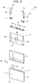
- FIG. 2 is an exploded perspective view of a prismatic secondary battery.
- the battery can 1 of the prismatic secondary battery 100 has a rectangular bottom surface 1d, wide surfaces 1b rising from a pair of long sides of the bottom surface 1d, narrow surfaces 1c rising from a pair of short sides of the bottom surface 1d, and an opening 1a opening upward in upper ends of the wide surfaces 1b and the narrow surfaces 1c.
- the wound electrode group 3 is contained in a state of being wrapped with an insulating protective film 2.
- the wound electrode group 3 is constituted by winding a band-shaped electrode in a flat shape, and has a pair of curved portions facing each other and having a semicircular shape in section, and planar portions continuously formed between the pair of curved portions.
- the wound electrode group 3 is inserted into the battery can 1 from one curved portion side to face the bottom surface 1d such that a winding axis direction goes along a lateral width direction of the battery can 1 and the other curved portion side is arranged on the opening 1a side.
- a positive electrode foil exposed portion 34c of the wound electrode group 3 is welded and joined to a positive electrode current collector plate 44 and is electrically connected to the positive electrode output portion 14 exposed from the lid 6. Further, a negative electrode foil exposed portion 32c of the wound electrode group 3 is welded and joined to a negative electrode current collector plate 24 and is electrically connected to the negative electrode output portion 12 exposed from the lid 6.
- the positive electrode current collector plate 44 and the negative electrode current collector plate 24 are fixed to the lid 6 by insert molding with an insulating member 5 and constitute a lid assembly in cooperation with the lid 6 (see FIG. 4 ).
- the positive electrode current collector plate 44 and the negative electrode current collector plate 24 have a positive electrode connection portion 42 and a negative electrode connection portion 22 to which the positive electrode foil exposed portion 34c and the negative electrode foil exposed portion 32c of the wound electrode group 3 are respectively welded and joined, and the wound electrode group 3 is integrally attached to the lid assembly.
- the positive electrode connection portion 42 and the positive electrode foil exposed portion 34c, and the negative electrode connection portion 22 and the negative electrode foil exposed portion 32c are welded and joined by ultrasonic welding, spot welding, or the like.
- the wound electrode group 3 is inserted into the battery can 1, the opening 1a of the battery can 1 is closed with the lid 6, the lid 6 is joined to the battery can 1 by laser welding, and the opening 1a is sealed. Then, after injecting an electrolytic solution into the battery can 1 through a liquid injection hole 9, a liquid injection plug 11 is joined to the lid 6 by laser welding to seal the liquid injection hole 9, thereby to tightly close the prismatic secondary battery 100.
- the positive electrode current collector plate 44 and the negative electrode current collector plate 24 are made of different metal materials from each other as main materials.
- a material for forming the positive electrode current collector plate 44 includes an aluminum alloy and a material for forming the negative electrode current collector plate 24 includes a copper alloy.
- examples of the material for forming the insulating member 5 include resin members having insulating properties such as polybutylene terephthalate, polyphenylene sulfide, and a perfluoroalkoxy fluorine resin.
- a nonaqueous electrolytic solution in which a lithium salt such as lithium hexafluorophosphate (LiPF 6 ) is dissolved in a carbonate ester organic solvent such as ethylene carbonate can be applied.
- the positive electrode current collector plate 44 and the negative electrode current collector plate 24 are integrally formed with the positive electrode output portion 14 and the negative electrode output portion 12 exposed from the lid 6.
- Each of the positive electrode output portion 14 and the negative electrode output portion 12 has a welded joint portion to be welded and joined to a bus bar or the like.
- the welded joint portion has a flat surface arranged above the insulating member 5 in parallel with an outer surface of the lid 6 and the bus bar or the like is brought into contact with and welded and joined to the flat surface.
- the positive electrode current collector plate 44 and the negative electrode current collector plate 24 are formed into flat plate shapes inserted into a positive electrode-side through hole 46 and a negative electrode-side through hole 26 and extending in a straight line toward the bottom surface along the wide surfaces of the battery can 1.
- the positive electrode current collector plate 44 and the negative electrode current collector plate 24 have distal ends extending up to positions facing the positive electrode foil exposed portion 34c and the negative electrode foil exposed portion 32c so that the positive electrode connection portion 42 and the negative electrode connection portion 22 can be stacked and connected to the positive electrode foil exposed portion 34c and the negative electrode foil exposed portion 32c of the wound electrode group 3.
- a periphery of the wound electrode group 3 is covered with the insulating protective film 2.
- the insulating protective film 2 is attached to wind around a direction along the flat surface of the wound electrode group 3 and orthogonal to the winding axis direction of the wound electrode group 3 as a central axis direction.
- the insulating protective film 2 is formed of a single sheet or a plurality of film members made of a synthetic resin such as polypropylene (PP), for example.
- FIG. 3 is an exploded perspective view illustrating a state in which a part of the wound electrode group is developed.
- the wound electrode group 3 is constituted by winding a negative electrode 32 and a positive electrode 34 with separators 33 and 35 interposed therebetween in a flat manner.
- an outermost electrode is the negative electrode 32, and the separators 33 and 35 are further wound around the negative electrode 32.
- the separators 33 and 35 serve to insulate the positive electrode 34 from the negative electrode 32.
- a negative electrode mixture layer 32b of the negative electrode 32 is formed to be larger in a width direction than a positive electrode mixture layer 34b of the positive electrode 34.
- the positive electrode mixture layer 34b is always sandwiched by the negative electrode mixture layer 32b.
- the positive electrode foil exposed portion 34c and the negative electrode foil exposed portion 32c are bundled in a flat thickness direction at a planar portion of the wound electrode group 3 and the positive electrode connection portion 42 of the positive electrode current collector plate 44 and the negative electrode connection portion 22 of the negative electrode current collector plate 24 are welded and joined.
- the separators 33 and 35 are wider in the width direction than a portion where the negative electrode mixture layer 32b is applied, the separators 33 and 35 are wound at positions of end portions where the metal foils are exposed by the positive electrode foil exposed portion 34c and the negative electrode foil exposed portion 32c, and thus does not affect the bundling and welding.
- the positive electrode 34 is constituted by applying a positive electrode active material mixture to both surfaces of a positive electrode foil that is a positive electrode current collector, and the positive electrode foil exposed portion 34c where no positive electrode active material mixture is applied is provided on an end portion on one side in the width direction of the positive electrode foil.
- the negative electrode 32 is constituted by applying a negative electrode active material mixture to both surfaces of a negative electrode foil that is a negative electrode current collector, and the negative electrode foil exposed portion 32c where no negative electrode active material mixture is applied is provided on an end portion on the other side in the width direction of the negative electrode foil.
- the positive electrode foil exposed portion 34c and the negative electrode foil exposed portion 32c are regions where a metal surface of the electrode foil is exposed.
- the positive electrode 34 and the negative electrode 32 are stacked and wound such that the positive electrode foil exposed portion 34c and the negative electrode foil exposed portion 32c are separately arranged at positions on one side and on the other side in the winding axis direction, thereby constituting the wound electrode group 3.
- the positive electrode foil and the negative electrode foil are made of different metal materials from each other and have different thicknesses.
- the positive electrode foil is made of an aluminum foil and the negative electrode foil is made of a copper foil, and the positive electrode foil is thicker in thickness than the negative electrode foil. Therefore, in a case where the positive electrode foil exposed portion 34c and the negative electrode foil exposed portion 32c are bundled at the planar portion of the wound electrode group 3 in the flat thickness direction, the positive electrode foil exposed portion 34c is thicker in thickness than the negative electrode foil exposed portion 32c.
- the negative electrode 32 10 parts by weight of polyvinylidene fluoride (hereinafter referred to as PVDF) as a binder was added to 100 parts by weight of amorphous carbon powder as a negative electrode active material, and N-methylpyrrolidone (hereinafter referred to as NMP) as a dispersion solvent was added thereto and kneaded to prepare a negative electrode mixture.
- This negative electrode mixture was applied on both surfaces of the copper foil (negative electrode foil) having the thickness of 10 ⁇ m while leaving welded portions (negative electrode uncoated portions). After that the negative electrode 32 with a negative electrode active material coated portion containing no copper foil having the thickness of 70 ⁇ m was obtained through a drying process, a press process, and a cutting process.
- the present embodiment is not limited to the example, and natural graphite capable of inserting and releasing lithium ions, various artificial graphite materials, carbonaceous materials such as coke, or compounds such as Si or Sn (for example, SiO or TiSi 2 ), or composite materials thereof may be adopted.
- the particle shape may be a scaly shape, a spherical shape, a fibrous shape, a lumpy shape, or the like, which is not particularly limited.
- the positive electrode 34 10 parts by weight of scaly graphite as a conductive material and 10 parts by weight of PVDF as a binder were added to 100 parts by weight of lithium manganate (chemical formula LiMn 2 O 4 ) as a positive electrode active material, and NMP as a dispersion solvent was added thereto and kneaded to prepare a positive electrode mixture.
- This positive electrode mixture was applied on both surfaces of the aluminum foil (positive electrode foil) having the thickness of 20 ⁇ m while leaving welded portions (positive electrode uncoated portions). After that the positive electrode 31 with a positive electrode active material coated portion containing no aluminum foil having the thickness of 90 ⁇ m was obtained through a drying process, a press process, and a cutting process.
- lithium manganate as the positive electrode active material
- another lithium manganate having a spinel crystal structure a lithium manganese composite oxide in which a part is substituted or doped with a metal element, lithium cobalt oxide or lithium titanate having a layered crystal structure, or a lithium-metal composite oxide in which a part of the above-described substance is substituted or doped with a metal element may be used.
- PVDF polytetrafluoroethylene
- polyethylene polyethylene
- polystyrene polybutadiene
- butyl rubber nitrile rubber
- styrene butadiene rubber polysulfide rubber
- nitrocellulose cyanoethyl cellulose
- various latexes acrylonitrile, vinyl fluoride, vinylidene fluoride, propylene fluoride, chloroprene fluoride, and an acrylic resin, and a mixture of the aforementioned polymers can be used.
- a shaft core for example, a core formed by winding a resin sheet having higher flexural rigidity than any of the positive electrode foil, the negative electrode foil, and the separators 33 and 35 can be used.
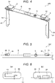
- FIG. 4 is a perspective view of the lid assembly of the first embodiment
- FIG. 5 is a partial cross-sectional view of the lid assembly of the first embodiment
- FIG. 6 is enlarged views of main portions of FIG. 5.
- FIG. 5 is a plan view of the lid assembly, illustrating a partial cross-sectional in which the lid assembly is partially cut along an upper surface of the lid
- FIG. 6(a) illustrates a partial cross section on the positive electrode side
- FIG. 6(b) illustrates a partial cross section on the negative electrode side.
- the positive electrode current collector plate 44 and the negative electrode current collector plate 24 are formed into flat plate shapes inserted into the positive electrode-side through hole 46 and the negative electrode-side through hole 26 provided in the lid 6 and extending in a straight line toward the bottom surface 1d along the wide surfaces 1b of the battery can 1.
- the term "straight line” refers to a state without having a bending process and a drawing process, and variation of material thickness due to a press process, a cutting process, and a finishing process is included in the definition of the straight line.
- the positive electrode current collector plate 44 and the negative electrode current collector plate 24 be in the straight line, the operation to insert the positive electrode-side through hole 46 and the negative electrode-side through hole 26 becomes easy, and the assemblability of the lid assembly is improved. In particular, when performing insert molding, arrangement of parts inside the mold becomes easy, and thus improvement of the productivity can be expected.
- the positive electrode current collector plate 44 and the negative electrode current collector plate 24 are made of different metal materials from each other as main materials and have different plate thicknesses from each other. In the present embodiment, the positive electrode current collector plate 44 made of an aluminum alloy is thicker in the plate thickness than the negative electrode current collector plate 24 made of a copper alloy.
- the positive electrode current collector plate 44 and the negative electrode current collector plate 24 of the lid assembly illustrated in FIG. 4 are integrally fixed to the lid 6 with the insulating member 5 in the state where the positive electrode current collector plate 44 and the negative electrode current collector plate 24 are inserted in the positive electrode-side through hole 46 and the negative electrode-side through hole 26 of the lid 6 by insert molding.
- the positive electrode-side through hole 46 and the negative electrode-side through hole 26 of the lid 6 are hermetically sealed with the insulating member 5.
- the insulating member 5 is arranged between the positive electrode current collector plate 44 and the positive electrode-side through hole 46 and between the negative electrode current collector plate 24 and the negative electrode-side through hole 26 to seal gaps therebetween.
- the roughening treatment is performed for an adhesion portion of the metal parts, whereby the metal and the insulating member 5 can strongly adhere and the hermeticity can be enhanced.
- the roughening treatment is applied to the entire surface of the lid 6 and the entire surfaces of the positive electrode current collector plate 44 and the negative electrode current collector plate 24.
- the roughening treatment may be applied limiting a range covered with the insulating member 5.
- the roughening treatment may be applied only to a portion of the lid 6, the portion being covered with the insulating member 5, and portions of the positive electrode current collector plate 44 and the negative electrode current collector plate 24, the portions being covered with the insulating member 5.
- the lid 6 is provided at a position where the positive electrode-side through hole 46 and the negative electrode-side through hole 26 deviate on a side of one of the wide surfaces with respect to the center Lc of the lid 6.
- both the positive electrode-side through hole 46 and the negative electrode-side through hole 26 are provided at positions deviating to an upper side in FIG. 5 .
- the positive electrode-side through hole 46 and the negative electrode-side through hole 26 have the same size.
- an insertion position of the positive electrode current collector plate 44 inserted in the positive electrode-side through hole 46 of the lid 6 deviates on a side of one wide surface with respect to an insertion position of the negative electrode current collector plate 24 inserted in the negative electrode-side through hole 26 of the lid 6.
- the positive electrode current collector plate 44 is arranged at a position separated from a center Lc of the lid by ⁇ 1 and the negative electrode current collector plate 24 is arranged at a position separated from the center Lc of the lid by ⁇ 2, and a deviation width from the center Lc of the lid 6 of the positive electrode current collector plate 44 is larger than that of the negative electrode current collector plate 24 ( ⁇ 1 > ⁇ 2).
- the positive electrode foil exposed portion 34c is thicker in the thickness than the negative electrode foil exposed portion 32c when bundled. Then, ⁇ 1 is set to about half the thickness when the positive electrode foil exposed portion 34c of the wound electrode group 3 is bundled, and ⁇ 2 is set to about half the thickness when the negative electrode foil exposed portion 32c of the wound group 3 is bundled.
- the positive electrode connection portion 42 of the positive electrode current collector plate 44 is brought into contact with the positive electrode foil exposed portion 34c of the wound electrode group 3 from the side of one wide surface
- the negative electrode connection portion 22 of the negative electrode current collector plate 24 is brought into contact with the negative electrode foil exposed portion 32c of the wound electrode group 3 from the side of one wide surface, whereby a center of the wound electrode group 3 in the flat thickness direction can be arranged to coincide with the center Lc of the lid 6.
- Center deviation of the wound electrode group 3 and the lid 6 can be suppressed by the arrangement relationship when the positive electrode foil and the negative electrode foil having different thicknesses are bundled and welded to the positive electrode current collector plate 44 and the negative electrode current collector plate 24. Therefore, since the center of the wound electrode group 3 in the flat thickness direction coincides with the center Lc of the lid 6, a necessary gap between the wound electrode group 3 and the battery can 1 can be minimized when the wound electrode group 3 of the lid subassembly is inserted into the battery can 1, whereby the mounting density is improved and a high-capacity battery can be realized.
- a gap between the positive electrode-side through hole 46 and the positive electrode current collector plate 44 and a gap between the negative electrode-side through hole 26 and the negative electrode current collector plate 24 are provided by 0.3 mm or more. Therefore, the fluidity of the insulating resin at the time of insert molding is improved, and the productivity is improved.
- the positive electrode current collector plate 44 and the negative electrode current collector plate 24 are formed in the flat plate shape extending in the straight line, the positive electrode current collector plate 44 and the negative electrode current collector plate 24 can be easily inserted into the positive electrode-side through hole 46 and the negative electrode-side through hole 26 of the lid 6, whereby the assemblability of the lid assembly can be improved.
- the wound electrode group 3 can be brought close to the positive electrode connection portion 42 of the positive electrode current collector plate 44 and the negative electrode connection portion 22 of the negative electrode current collector plate 24 from a side of the other wide surface, and the positive electrode foil exposed portion 34c and the negative electrode foil exposed portion 32c can be brought into contact with and joined to the positive electrode connection portion 42 and the negative electrode connection portion 22, when the wound electrode group 3 is attached to the lid assembly. Therefore, the wound electrode group 3 can be mounted by a simple layering operation method and manufacturing can be facilitated.
- FIG. 7 is a partial cross-sectional view of a lid assembly of a second embodiment
- FIG. 8 is enlarged views of main parts of FIG. 7 . Note that the same reference numerals are given to similar constituent elements to those in the above-described embodiment, and detailed description thereof is omitted.
- Characteristics in the present embodiment are that a positive electrode-side through hole 46 and a positive electrode current collector plate 44 are arranged on a side of one wide surface and a negative electrode-side through hole 26 and a negative electrode current collector plate 24 are arranged on a side of the other wide surface with respect to a center Lc of a lid 6.
- the positive electrode-side through hole 46 is provided on the side of one wide surface and the negative electrode-side through hole 26 is provided on the side of the other wide surface.
- an insertion position of the positive electrode current collector plate 44 inserted in the positive electrode-side through hole 46 of the lid 6 deviates on the side of one wide surface on the basis of the center Lc of the lid 6.
- an insertion position of the negative electrode current collector plate 24 inserted in the negative electrode-side through hole 26 of the lid 6 deviates on the side of the other wide surface on the basis of the center Lc of the lid 6.
- the positive electrode current collector plate 44 is arranged at a position separated from the center Lc of the lid by ⁇ 3 on the side of one wide surface and the negative electrode current collector plate 24 is arranged at a position separated from the center Lc of the lid by ⁇ 4 on the side of the other wide surface, and a deviation width from the center Lc of the lid 6 of the positive electrode current collector plate 44 is larger than that of the negative electrode current collector plate 24 ( ⁇ 3 > ⁇ 4).
- ⁇ 3 is set to about half the thickness when the positive electrode foil exposed portion 34c of the wound electrode group 3 is bundled, and ⁇ 4 is set to about half the thickness when the negative electrode foil exposed portion 32c of the wound group 3 is bundled. Therefore, the positive electrode connection portion 42 of the positive electrode current collector plate 44 is brought into contact with the positive electrode foil exposed portion 34c of the wound electrode group 3 from the side of one wide surface, and the negative electrode connection portion 22 of the negative electrode current collector plate 24 is brought into contact with the negative electrode foil exposed portion 32c of the wound electrode group 3 from the side of the other wide surface, whereby a center of the wound electrode group 3 in the flat thickness direction can be arranged to coincide with the center Lc of the lid 6.
- Center deviation of the wound electrode group 3 and the lid 6 can be suppressed by the arrangement relationship when the positive electrode foil and the negative electrode foil having different thicknesses are bundled and welded to the positive electrode current collector plate 44 and the negative electrode current collector plate 24, similarly to the first embodiment. Therefore, since the center of the wound electrode group 3 in the flat thickness direction coincides with the center Lc of the lid 6, a necessary gap between the wound electrode group 3 and the battery can 1 can be minimized when the wound electrode group 3 of the lid subassembly is inserted into the battery can 1, whereby the mounting density is improved and a high-capacity battery can be realized.
- a gap between the positive electrode-side through hole 46 and the positive electrode current collector plate 44 and a gap between the negative electrode-side through hole 26 and the negative electrode current collector plate 24 are provided by 0.3 mm or more. Therefore, the fluidity of the insulating resin at the time of insert molding is improved, and the productivity is improved.
- the positive electrode current collector plate 44 and the negative electrode current collector plate 24 are formed in the flat plate shape extending in the straight line, the positive electrode current collector plate 44 and the negative electrode current collector plate 24 can be easily inserted into the positive electrode-side through hole 46 and the negative electrode-side through hole 26 of the lid 6, whereby the assemblability of the lid assembly can be improved, similarly to the first embodiment.
- the positive electrode-side through hole 46 and the negative electrode-side through hole 26 are arranged at positions separated from each other on a diagonal line of the lid 6. Therefore, in a case where the positive electrode-side through hole 46 and the negative electrode-side through hole 26 are formed in the lid 6 by pressing, a pressure is equally applied to a short side direction of the lid 6, and distortion of the lid 6 can be prevented.
- FIG. 9 is a partial cross-sectional view of an insulating member of a lid assembly of a third embodiment. Note that the same reference numerals are given to similar constituent elements to those in the above-described first and second embodiments, and detailed description thereof is omitted.
- Characteristics in the present embodiment are that, in the above-described first or second embodiments, the negative electrode current collector plate 24 is constituted using a cladding material and a cladding conversion portion 80 of the negative electrode current collector plate 24 is arranged at a position covered with an insulating resin.
- the negative electrode current collector plate 24 is constituted using a clad material formed by joining dissimilar metals by cladding. Specifically, a negative electrode connection portion 22 of a copper alloy and a negative electrode output portion 12 of an aluminum alloy are joined by cladding with the cladding conversion portion 80. Then, the cladding conversion portion 80 is arranged in a portion covered with an insulating member 5 and is in a state where contact with the outside is deprived. Therefore, generation of a metal compound at an interface of the cladding conversion portion 80 can be suppressed.
- the negative electrode output portion 12 is constituted by an aluminum alloy, whereby a bus bar joined to the negative electrode output portion 12 can be made of an aluminum alloy, and can be of the same material as a bus bar joined to the positive electrode output portion 14. Therefore, preparation of two types of bus bars is not necessary and the cost can be suppressed to be low.
- the present invention is not limited to the above-described embodiments, and various design changes can be made without departing from the spirit of the present invention described in the claims.
- the above embodiments have been described in detail for describing the present invention in an easy-tounderstand manner, and the present invention is not necessarily limited to one including all the described configurations.
- a part of the configuration of a certain embodiment can be replaced with the configuration of another embodiment.
- the configuration of another embodiment can be added to the configuration of a certain embodiment.
- another configuration can be added to/deleted from/replaced with a part of the configurations of the embodiments.
Landscapes
- Chemical & Material Sciences (AREA)
- Chemical Kinetics & Catalysis (AREA)
- Electrochemistry (AREA)
- General Chemical & Material Sciences (AREA)
- Connection Of Batteries Or Terminals (AREA)
- Sealing Battery Cases Or Jackets (AREA)
- Secondary Cells (AREA)
- Cell Electrode Carriers And Collectors (AREA)
Description
- The present invention relates to a prismatic secondary battery having an electrode terminal supported by a lid of a battery can via an insulating member.
- As a conventional example,
PTL 1 discloses a prismatic secondary battery in which a power generating body is contained in a metal battery case having a bottomed quadrilateral box shape having a rectangular opening in one end, and the opening is hermetically sealed by a rectangular plate-like metal lid member fixed to the battery case, wherein one end (a lower end) of a metal terminal plate (current collector plate) is electrically connected to the power generating body inside the battery case, the other end (an upper end) penetrates a through hole formed in the lid member in a non-contact state with the lid member and protrudes in an outward (upward) direction of the lid member, and the through hole is sealed by an insulating mold portion made of a synthetic resin molded on the lid member by insert molding including the other end side of the terminal plate.PTL 2 shows a battery unit which includes: a case accommodating an electrode assembly and having an opening; a cap plate covering the opening and having a terminal insertion portion penetrating the cap plate; a terminal member extending into the case through the terminal insertion portion to electrically expose the electrode assembly outside of the case; and a fixing member in the terminal insertion portion and fixing the terminal member to the cap plate.PTL 3 discloses a lid member of a battery case has a protruding section including an inside-outside direction an outside tapered surface, and a top surface between the inside tapered surface and the outside tapered surface. PTL 4 shows an electrode terminal fitting structure which has a battery outer packaging member, an insertion part inserted into an opening part of the battery outer packaging member, an electrode terminal conductively provided on one side of the outside of the battery outer packaging member of the insertion part, and an electrode member having a current collecting part conductively provided on the other side of the inside of the battery outer packaging member of the insertion part.PTL 5 describes a polyarylene sulfide resin composition and a seal member for a plate for sealing an opening of a second battery. - Citation List
-
- PTL 1:
JP 2012-243405 A - PTL 2:
US 2014/302380 A1 - PTL 3:
US 2015/179992 A1 - PTL 4:
JP 2009 076385 A - PTL 5:
JP 2016 044303 A - In the prismatic secondary battery of the conventional example, the metal terminal plate (current collector plate) inserted into the battery case is processed such that the battery case side of the metal terminal plate (current collector plate) is bent or drawn by pressing. Then, at the time of insert molding, the metal terminal plate (current collector plate) is inserted into the opening of the rectangular plate-like metal lid member in the mold. Therefore, there is a possibility that the mold structure becomes complicated and the productivity is reduced. Furthermore, in a case where the battery case and the power generating body are shifted from each other, there is a possibility that the mounting density is reduced.
- The present invention has been made in view of the above points, and an object of the present invention is to provide a prismatic secondary battery with improved productivity and mounting density.
- The aforementioned object is solved by the invention according to the
independent claims - Further preferred developments are described by the dependent claims.
- According to the present invention, deviation of center positions of a wound electrode group and a battery container can be suppressed, and a prismatic secondary battery with improved mounting density can be provided. Note that problems, configurations, and effects other than those described above will be clarified from description of the following embodiments.
-
- [
FIG. 1] FIG. 1 is an external perspective view of a prismatic secondary battery. - [
FIG. 2] FIG. 2 is an exploded perspective view of a prismatic secondary battery. - [
FIG. 3] FIG. 3 is an exploded perspective view of a wound electrode group. - [
FIG. 4] FIG. 4 is a perspective view of a lid assembly of a first embodiment. - [
FIG. 5] FIG. 5 is a partial cross-sectional view of the lid assembly of the first embodiment. - [
FIG. 6] FIG. 6 is enlarged views of main portions ofFIG. 5 . - [
FIG. 7] FIG. 7 is a partial cross-sectional view of a lid assembly of a second embodiment. - [
FIG. 8] FIG. 8 is enlarged views of main portions ofFIG. 7 . - [
FIG. 9] FIG. 9 is a partial cross-sectional view of an insulating member of a lid assembly of a third embodiment. - Hereinafter, embodiments of the present invention will be described with reference to the drawings.
-
FIG. 1 is an external perspective view of a prismatic secondary battery. - The prismatic
secondary battery 100 includes a battery can (battery container) 1 and alid 6. The battery can 1 and thelid 6 are made of a metal material such as an aluminum alloy, for example, and are formed by deep drawing and pressing. - In the battery can 1, a wound electrode group 3 (see
FIG. 2 ) as an electric storage element is built in, and the opening 1a of the battery can 1 is sealed with alid 6. Thelid 6 has a substantially rectangular flat plate shape and is welded so as to close the opening 1a of the battery can 1 to seal the battery can 1. Thelid 6 is provided with a positiveelectrode output portion 14 and a negativeelectrode output portion 12. The prismaticsecondary battery 100 is charged via the positiveelectrode output portion 14 and the negativeelectrode output portion 12, and power is supplied to the external load. Agas discharge valve 10 is integrally provided in thelid 6, and when the pressure inside the battery can 1 rises, thegas discharge valve 10 opens, gas is discharged from the inside, and the pressure inside the battery can 1 is reduced. As a result, the safety of the prismaticsecondary battery 100 is secured. -
FIG. 2 is an exploded perspective view of a prismatic secondary battery. - The battery can 1 of the prismatic
secondary battery 100 has arectangular bottom surface 1d,wide surfaces 1b rising from a pair of long sides of thebottom surface 1d,narrow surfaces 1c rising from a pair of short sides of thebottom surface 1d, and an opening 1a opening upward in upper ends of thewide surfaces 1b and thenarrow surfaces 1c. In the battery can 1, thewound electrode group 3 is contained in a state of being wrapped with an insulatingprotective film 2. - The
wound electrode group 3 is constituted by winding a band-shaped electrode in a flat shape, and has a pair of curved portions facing each other and having a semicircular shape in section, and planar portions continuously formed between the pair of curved portions. Thewound electrode group 3 is inserted into the battery can 1 from one curved portion side to face thebottom surface 1d such that a winding axis direction goes along a lateral width direction of the battery can 1 and the other curved portion side is arranged on the opening 1a side. - A positive electrode foil exposed
portion 34c of thewound electrode group 3 is welded and joined to a positive electrodecurrent collector plate 44 and is electrically connected to the positiveelectrode output portion 14 exposed from thelid 6. Further, a negative electrode foil exposedportion 32c of thewound electrode group 3 is welded and joined to a negative electrodecurrent collector plate 24 and is electrically connected to the negativeelectrode output portion 12 exposed from thelid 6. With the configuration, the power is supplied from thewound electrode group 3 to the external load via the positive electrodecurrent collector plate 44 and the negative electrodecurrent collector plate 24, and externally generated power is supplied and charged to thewound electrode group 3 via the positive electrodecurrent collector plate 44 and the negative electrodecurrent collector plate 24. - The positive electrode
current collector plate 44 and the negative electrodecurrent collector plate 24 are fixed to thelid 6 by insert molding with aninsulating member 5 and constitute a lid assembly in cooperation with the lid 6 (seeFIG. 4 ). The positive electrodecurrent collector plate 44 and the negative electrodecurrent collector plate 24 have a positiveelectrode connection portion 42 and a negativeelectrode connection portion 22 to which the positive electrode foil exposedportion 34c and the negative electrode foil exposedportion 32c of thewound electrode group 3 are respectively welded and joined, and thewound electrode group 3 is integrally attached to the lid assembly. The positiveelectrode connection portion 42 and the positive electrode foil exposedportion 34c, and the negativeelectrode connection portion 22 and the negative electrode foil exposedportion 32c are welded and joined by ultrasonic welding, spot welding, or the like. Then, thewound electrode group 3 is inserted into the battery can 1, the opening 1a of the battery can 1 is closed with thelid 6, thelid 6 is joined to the battery can 1 by laser welding, and theopening 1a is sealed. Then, after injecting an electrolytic solution into the battery can 1 through aliquid injection hole 9, aliquid injection plug 11 is joined to thelid 6 by laser welding to seal theliquid injection hole 9, thereby to tightly close the prismaticsecondary battery 100. - The positive electrode
current collector plate 44 and the negative electrodecurrent collector plate 24 are made of different metal materials from each other as main materials. In the present embodiment, a material for forming the positive electrodecurrent collector plate 44 includes an aluminum alloy and a material for forming the negative electrodecurrent collector plate 24 includes a copper alloy. Further, examples of the material for forming the insulatingmember 5 include resin members having insulating properties such as polybutylene terephthalate, polyphenylene sulfide, and a perfluoroalkoxy fluorine resin. - Then, as the electrolytic solution to be injected into the battery can 1, a nonaqueous electrolytic solution in which a lithium salt such as lithium hexafluorophosphate (LiPF6) is dissolved in a carbonate ester organic solvent such as ethylene carbonate can be applied.
- The positive electrode
current collector plate 44 and the negative electrodecurrent collector plate 24 are integrally formed with the positiveelectrode output portion 14 and the negativeelectrode output portion 12 exposed from thelid 6. Each of the positiveelectrode output portion 14 and the negativeelectrode output portion 12 has a welded joint portion to be welded and joined to a bus bar or the like. The welded joint portion has a flat surface arranged above the insulatingmember 5 in parallel with an outer surface of thelid 6 and the bus bar or the like is brought into contact with and welded and joined to the flat surface. - The positive electrode
current collector plate 44 and the negative electrodecurrent collector plate 24 are formed into flat plate shapes inserted into a positive electrode-side throughhole 46 and a negative electrode-side throughhole 26 and extending in a straight line toward the bottom surface along the wide surfaces of the battery can 1. The positive electrodecurrent collector plate 44 and the negative electrodecurrent collector plate 24 have distal ends extending up to positions facing the positive electrode foil exposedportion 34c and the negative electrode foil exposedportion 32c so that the positiveelectrode connection portion 42 and the negativeelectrode connection portion 22 can be stacked and connected to the positive electrode foil exposedportion 34c and the negative electrode foil exposedportion 32c of thewound electrode group 3. - A periphery of the
wound electrode group 3 is covered with the insulatingprotective film 2. The insulatingprotective film 2 is attached to wind around a direction along the flat surface of thewound electrode group 3 and orthogonal to the winding axis direction of thewound electrode group 3 as a central axis direction. The insulatingprotective film 2 is formed of a single sheet or a plurality of film members made of a synthetic resin such as polypropylene (PP), for example. -
FIG. 3 is an exploded perspective view illustrating a state in which a part of the wound electrode group is developed. - The
wound electrode group 3 is constituted by winding a negative electrode 32 and apositive electrode 34 withseparators wound electrode group 3, an outermost electrode is the negative electrode 32, and theseparators separators positive electrode 34 from the negative electrode 32. - A negative
electrode mixture layer 32b of the negative electrode 32 is formed to be larger in a width direction than a positiveelectrode mixture layer 34b of thepositive electrode 34. In a case where thepositive electrode 34 and the negative electrode 32 are stacked and wound, the positiveelectrode mixture layer 34b is always sandwiched by the negativeelectrode mixture layer 32b. The positive electrode foil exposedportion 34c and the negative electrode foil exposedportion 32c are bundled in a flat thickness direction at a planar portion of thewound electrode group 3 and the positiveelectrode connection portion 42 of the positive electrodecurrent collector plate 44 and the negativeelectrode connection portion 22 of the negative electrodecurrent collector plate 24 are welded and joined. Although theseparators electrode mixture layer 32b is applied, theseparators portion 34c and the negative electrode foil exposedportion 32c, and thus does not affect the bundling and welding. - The
positive electrode 34 is constituted by applying a positive electrode active material mixture to both surfaces of a positive electrode foil that is a positive electrode current collector, and the positive electrode foil exposedportion 34c where no positive electrode active material mixture is applied is provided on an end portion on one side in the width direction of the positive electrode foil. The negative electrode 32 is constituted by applying a negative electrode active material mixture to both surfaces of a negative electrode foil that is a negative electrode current collector, and the negative electrode foil exposedportion 32c where no negative electrode active material mixture is applied is provided on an end portion on the other side in the width direction of the negative electrode foil. The positive electrode foil exposedportion 34c and the negative electrode foil exposedportion 32c are regions where a metal surface of the electrode foil is exposed. Thepositive electrode 34 and the negative electrode 32 are stacked and wound such that the positive electrode foil exposedportion 34c and the negative electrode foil exposedportion 32c are separately arranged at positions on one side and on the other side in the winding axis direction, thereby constituting thewound electrode group 3. - The positive electrode foil and the negative electrode foil are made of different metal materials from each other and have different thicknesses. In the present embodiment, the positive electrode foil is made of an aluminum foil and the negative electrode foil is made of a copper foil, and the positive electrode foil is thicker in thickness than the negative electrode foil. Therefore, in a case where the positive electrode foil exposed
portion 34c and the negative electrode foil exposedportion 32c are bundled at the planar portion of thewound electrode group 3 in the flat thickness direction, the positive electrode foil exposedportion 34c is thicker in thickness than the negative electrode foil exposedportion 32c. - Regarding the
negative electrode 32, 10 parts by weight of polyvinylidene fluoride (hereinafter referred to as PVDF) as a binder was added to 100 parts by weight of amorphous carbon powder as a negative electrode active material, and N-methylpyrrolidone (hereinafter referred to as NMP) as a dispersion solvent was added thereto and kneaded to prepare a negative electrode mixture. This negative electrode mixture was applied on both surfaces of the copper foil (negative electrode foil) having the thickness of 10 µm while leaving welded portions (negative electrode uncoated portions). After that the negative electrode 32 with a negative electrode active material coated portion containing no copper foil having the thickness of 70 µm was obtained through a drying process, a press process, and a cutting process. - Note that, in the present embodiment, the case where amorphous carbon is used as the negative electrode active material has been exemplified. However, the present embodiment is not limited to the example, and natural graphite capable of inserting and releasing lithium ions, various artificial graphite materials, carbonaceous materials such as coke, or compounds such as Si or Sn (for example, SiO or TiSi2), or composite materials thereof may be adopted. Further, the particle shape may be a scaly shape, a spherical shape, a fibrous shape, a lumpy shape, or the like, which is not particularly limited.
- Regarding the
positive electrode - Further, in the present embodiment, the case of using lithium manganate as the positive electrode active material has been exemplified. However, another lithium manganate having a spinel crystal structure, a lithium manganese composite oxide in which a part is substituted or doped with a metal element, lithium cobalt oxide or lithium titanate having a layered crystal structure, or a lithium-metal composite oxide in which a part of the above-described substance is substituted or doped with a metal element may be used.
- Further, in the present embodiment, the case where PVDF is used as the binder in the coated portions of the positive electrode and the negative electrode has been exemplified. However, polymers such as polytetrafluoroethylene (PTFE), polyethylene, polystyrene, polybutadiene, butyl rubber, nitrile rubber, styrene butadiene rubber, polysulfide rubber, nitrocellulose, cyanoethyl cellulose, various latexes, acrylonitrile, vinyl fluoride, vinylidene fluoride, propylene fluoride, chloroprene fluoride, and an acrylic resin, and a mixture of the aforementioned polymers can be used.
- Further, as a shaft core, for example, a core formed by winding a resin sheet having higher flexural rigidity than any of the positive electrode foil, the negative electrode foil, and the
separators -
FIG. 4 is a perspective view of the lid assembly of the first embodiment,FIG. 5 is a partial cross-sectional view of the lid assembly of the first embodiment, andFIG. 6 is enlarged views of main portions ofFIG. 5. FIG. 5 is a plan view of the lid assembly, illustrating a partial cross-sectional in which the lid assembly is partially cut along an upper surface of the lid,FIG. 6(a) illustrates a partial cross section on the positive electrode side andFIG. 6(b) illustrates a partial cross section on the negative electrode side. - The positive electrode
current collector plate 44 and the negative electrodecurrent collector plate 24 are formed into flat plate shapes inserted into the positive electrode-side throughhole 46 and the negative electrode-side throughhole 26 provided in thelid 6 and extending in a straight line toward thebottom surface 1d along thewide surfaces 1b of the battery can 1. The term "straight line" refers to a state without having a bending process and a drawing process, and variation of material thickness due to a press process, a cutting process, and a finishing process is included in the definition of the straight line. - By making the positive electrode
current collector plate 44 and the negative electrodecurrent collector plate 24 be in the straight line, the operation to insert the positive electrode-side throughhole 46 and the negative electrode-side throughhole 26 becomes easy, and the assemblability of the lid assembly is improved. In particular, when performing insert molding, arrangement of parts inside the mold becomes easy, and thus improvement of the productivity can be expected. The positive electrodecurrent collector plate 44 and the negative electrodecurrent collector plate 24 are made of different metal materials from each other as main materials and have different plate thicknesses from each other. In the present embodiment, the positive electrodecurrent collector plate 44 made of an aluminum alloy is thicker in the plate thickness than the negative electrodecurrent collector plate 24 made of a copper alloy. - As described above, the positive electrode
current collector plate 44 and the negative electrodecurrent collector plate 24 of the lid assembly illustrated inFIG. 4 are integrally fixed to thelid 6 with the insulatingmember 5 in the state where the positive electrodecurrent collector plate 44 and the negative electrodecurrent collector plate 24 are inserted in the positive electrode-side throughhole 46 and the negative electrode-side throughhole 26 of thelid 6 by insert molding. As a result, the positive electrode-side throughhole 46 and the negative electrode-side throughhole 26 of thelid 6 are hermetically sealed with the insulatingmember 5. The insulatingmember 5 is arranged between the positive electrodecurrent collector plate 44 and the positive electrode-side throughhole 46 and between the negative electrodecurrent collector plate 24 and the negative electrode-side throughhole 26 to seal gaps therebetween. - When fixing the insulating
member 5 and thelid 6, or the insulatingmember 5 and the positive electrodecurrent collector plate 44 and the negative electrodecurrent collector plate 24 by insert molding, roughening treatment is performed for an adhesion portion of the metal parts, whereby the metal and the insulatingmember 5 can strongly adhere and the hermeticity can be enhanced. In the present embodiment, the roughening treatment is applied to the entire surface of thelid 6 and the entire surfaces of the positive electrodecurrent collector plate 44 and the negative electrodecurrent collector plate 24. The roughening treatment may be applied limiting a range covered with the insulatingmember 5. For example, the roughening treatment may be applied only to a portion of thelid 6, the portion being covered with the insulatingmember 5, and portions of the positive electrodecurrent collector plate 44 and the negative electrodecurrent collector plate 24, the portions being covered with the insulatingmember 5. - As illustrated in
FIG. 5 , thelid 6 is provided at a position where the positive electrode-side throughhole 46 and the negative electrode-side throughhole 26 deviate on a side of one of the wide surfaces with respect to the center Lc of thelid 6. In the example illustrated inFIG. 5 , both the positive electrode-side throughhole 46 and the negative electrode-side throughhole 26 are provided at positions deviating to an upper side inFIG. 5 . In the present embodiment the positive electrode-side throughhole 46 and the negative electrode-side throughhole 26 have the same size. - Then, as illustrated in
FIG. 6 , regarding the positive electrodecurrent collector plate 44 and the negative electrodecurrent collector plate 24, an insertion position of the positive electrodecurrent collector plate 44 inserted in the positive electrode-side throughhole 46 of thelid 6 deviates on a side of one wide surface with respect to an insertion position of the negative electrodecurrent collector plate 24 inserted in the negative electrode-side throughhole 26 of thelid 6. In the present embodiment, the positive electrodecurrent collector plate 44 is arranged at a position separated from a center Lc of the lid by δ1 and the negative electrodecurrent collector plate 24 is arranged at a position separated from the center Lc of the lid by δ2, and a deviation width from the center Lc of thelid 6 of the positive electrodecurrent collector plate 44 is larger than that of the negative electrode current collector plate 24 (δ1 > δ2). - In the
wound electrode group 3, the positive electrode foil exposedportion 34c is thicker in the thickness than the negative electrode foil exposedportion 32c when bundled. Then, δ1 is set to about half the thickness when the positive electrode foil exposedportion 34c of thewound electrode group 3 is bundled, and δ2 is set to about half the thickness when the negative electrode foil exposedportion 32c of thewound group 3 is bundled. - Therefore, the positive
electrode connection portion 42 of the positive electrodecurrent collector plate 44 is brought into contact with the positive electrode foil exposedportion 34c of thewound electrode group 3 from the side of one wide surface, and the negativeelectrode connection portion 22 of the negative electrodecurrent collector plate 24 is brought into contact with the negative electrode foil exposedportion 32c of thewound electrode group 3 from the side of one wide surface, whereby a center of thewound electrode group 3 in the flat thickness direction can be arranged to coincide with the center Lc of thelid 6. - Center deviation of the
wound electrode group 3 and thelid 6 can be suppressed by the arrangement relationship when the positive electrode foil and the negative electrode foil having different thicknesses are bundled and welded to the positive electrodecurrent collector plate 44 and the negative electrodecurrent collector plate 24. Therefore, since the center of thewound electrode group 3 in the flat thickness direction coincides with the center Lc of thelid 6, a necessary gap between thewound electrode group 3 and the battery can 1 can be minimized when thewound electrode group 3 of the lid subassembly is inserted into the battery can 1, whereby the mounting density is improved and a high-capacity battery can be realized. - In the present embodiment, a gap between the positive electrode-side through
hole 46 and the positive electrodecurrent collector plate 44 and a gap between the negative electrode-side throughhole 26 and the negative electrodecurrent collector plate 24 are provided by 0.3 mm or more. Therefore, the fluidity of the insulating resin at the time of insert molding is improved, and the productivity is improved. - According to the present embodiment, since the positive electrode
current collector plate 44 and the negative electrodecurrent collector plate 24 are formed in the flat plate shape extending in the straight line, the positive electrodecurrent collector plate 44 and the negative electrodecurrent collector plate 24 can be easily inserted into the positive electrode-side throughhole 46 and the negative electrode-side throughhole 26 of thelid 6, whereby the assemblability of the lid assembly can be improved. Then, by making the insertion positions of the positive electrodecurrent collector plate 44 and the negative electrodecurrent collector plate 24 deviate on the side of the one wide surface to have different distances from each other from the center Lc of the lid, considering the difference in the thickness between the positive electrode foil and the negative electrode foil of thewound electrode group 3, thereby to suppress the positional deviation between the center of thewound electrode group 3 and the center of the battery can 1 and improve the mounting density. - Further, in the present embodiment, since both the positive electrode-side through
hole 46 and the negative electrode-side throughhole 26 deviate on the side of one wide surface with respect to the center of thelid 6, thewound electrode group 3 can be brought close to the positiveelectrode connection portion 42 of the positive electrodecurrent collector plate 44 and the negativeelectrode connection portion 22 of the negative electrodecurrent collector plate 24 from a side of the other wide surface, and the positive electrode foil exposedportion 34c and the negative electrode foil exposedportion 32c can be brought into contact with and joined to the positiveelectrode connection portion 42 and the negativeelectrode connection portion 22, when thewound electrode group 3 is attached to the lid assembly. Therefore, thewound electrode group 3 can be mounted by a simple layering operation method and manufacturing can be facilitated. -
FIG. 7 is a partial cross-sectional view of a lid assembly of a second embodiment, andFIG. 8 is enlarged views of main parts ofFIG. 7 . Note that the same reference numerals are given to similar constituent elements to those in the above-described embodiment, and detailed description thereof is omitted. - Characteristics in the present embodiment are that a positive electrode-side through
hole 46 and a positive electrodecurrent collector plate 44 are arranged on a side of one wide surface and a negative electrode-side throughhole 26 and a negative electrodecurrent collector plate 24 are arranged on a side of the other wide surface with respect to a center Lc of alid 6. - In the present embodiment, as illustrated in
FIG. 7 , the positive electrode-side throughhole 46 is provided on the side of one wide surface and the negative electrode-side throughhole 26 is provided on the side of the other wide surface. Then, as illustrated inFIG. 8 , an insertion position of the positive electrodecurrent collector plate 44 inserted in the positive electrode-side throughhole 46 of thelid 6 deviates on the side of one wide surface on the basis of the center Lc of thelid 6. Then, an insertion position of the negative electrodecurrent collector plate 24 inserted in the negative electrode-side throughhole 26 of thelid 6 deviates on the side of the other wide surface on the basis of the center Lc of thelid 6. In the present embodiment, the positive electrodecurrent collector plate 44 is arranged at a position separated from the center Lc of the lid by δ3 on the side of one wide surface and the negative electrodecurrent collector plate 24 is arranged at a position separated from the center Lc of the lid by δ4 on the side of the other wide surface, and a deviation width from the center Lc of thelid 6 of the positive electrodecurrent collector plate 44 is larger than that of the negative electrode current collector plate 24 (δ3 > δ4). - δ3 is set to about half the thickness when the positive electrode foil exposed
portion 34c of thewound electrode group 3 is bundled, and δ4 is set to about half the thickness when the negative electrode foil exposedportion 32c of thewound group 3 is bundled. Therefore, the positiveelectrode connection portion 42 of the positive electrodecurrent collector plate 44 is brought into contact with the positive electrode foil exposedportion 34c of thewound electrode group 3 from the side of one wide surface, and the negativeelectrode connection portion 22 of the negative electrodecurrent collector plate 24 is brought into contact with the negative electrode foil exposedportion 32c of thewound electrode group 3 from the side of the other wide surface, whereby a center of thewound electrode group 3 in the flat thickness direction can be arranged to coincide with the center Lc of thelid 6. - Center deviation of the
wound electrode group 3 and thelid 6 can be suppressed by the arrangement relationship when the positive electrode foil and the negative electrode foil having different thicknesses are bundled and welded to the positive electrodecurrent collector plate 44 and the negative electrodecurrent collector plate 24, similarly to the first embodiment. Therefore, since the center of thewound electrode group 3 in the flat thickness direction coincides with the center Lc of thelid 6, a necessary gap between thewound electrode group 3 and the battery can 1 can be minimized when thewound electrode group 3 of the lid subassembly is inserted into the battery can 1, whereby the mounting density is improved and a high-capacity battery can be realized. - In the present embodiment, a gap between the positive electrode-side through
hole 46 and the positive electrodecurrent collector plate 44 and a gap between the negative electrode-side throughhole 26 and the negative electrodecurrent collector plate 24 are provided by 0.3 mm or more. Therefore, the fluidity of the insulating resin at the time of insert molding is improved, and the productivity is improved. - According to the present embodiment, since the positive electrode
current collector plate 44 and the negative electrodecurrent collector plate 24 are formed in the flat plate shape extending in the straight line, the positive electrodecurrent collector plate 44 and the negative electrodecurrent collector plate 24 can be easily inserted into the positive electrode-side throughhole 46 and the negative electrode-side throughhole 26 of thelid 6, whereby the assemblability of the lid assembly can be improved, similarly to the first embodiment. Then, by making the insertion positions of the positive electrodecurrent collector plate 44 and the negative electrodecurrent collector plate 24 deviate on the side of the one wide surface and on the side of the other wide surface to have different distances from each other from the center Lc of the lid, considering the difference in the thickness between the positive electrode foil and the negative electrode foil of thewound electrode group 3, thereby to suppress the positional deviation between the center of thewound electrode group 3 and the center of the battery can 1 and improve the mounting density. - According to the present embodiment, the positive electrode-side through
hole 46 and the negative electrode-side throughhole 26 are arranged at positions separated from each other on a diagonal line of thelid 6. Therefore, in a case where the positive electrode-side throughhole 46 and the negative electrode-side throughhole 26 are formed in thelid 6 by pressing, a pressure is equally applied to a short side direction of thelid 6, and distortion of thelid 6 can be prevented. -
FIG. 9 is a partial cross-sectional view of an insulating member of a lid assembly of a third embodiment. Note that the same reference numerals are given to similar constituent elements to those in the above-described first and second embodiments, and detailed description thereof is omitted. - Characteristics in the present embodiment are that, in the above-described first or second embodiments, the negative electrode
current collector plate 24 is constituted using a cladding material and acladding conversion portion 80 of the negative electrodecurrent collector plate 24 is arranged at a position covered with an insulating resin. - The negative electrode
current collector plate 24 is constituted using a clad material formed by joining dissimilar metals by cladding. Specifically, a negativeelectrode connection portion 22 of a copper alloy and a negativeelectrode output portion 12 of an aluminum alloy are joined by cladding with thecladding conversion portion 80. Then, thecladding conversion portion 80 is arranged in a portion covered with an insulatingmember 5 and is in a state where contact with the outside is deprived. Therefore, generation of a metal compound at an interface of thecladding conversion portion 80 can be suppressed. - In the present embodiment, the negative
electrode output portion 12 is constituted by an aluminum alloy, whereby a bus bar joined to the negativeelectrode output portion 12 can be made of an aluminum alloy, and can be of the same material as a bus bar joined to the positiveelectrode output portion 14. Therefore, preparation of two types of bus bars is not necessary and the cost can be suppressed to be low. - Note that, in the example illustrated in
FIG. 9 , only the configuration on the negative electrode side has been illustrated. However, an embodiment is not limited to the example as long as either the positive electrode side or the negative electrode side has the configuration, and the positive electrode side may have a similar configuration in place of the negative electrode side. - Although the embodiments of the present invention have been described in detail, the present invention is not limited to the above-described embodiments, and various design changes can be made without departing from the spirit of the present invention described in the claims. For example, the above embodiments have been described in detail for describing the present invention in an easy-tounderstand manner, and the present invention is not necessarily limited to one including all the described configurations. Further, a part of the configuration of a certain embodiment can be replaced with the configuration of another embodiment. Further, the configuration of another embodiment can be added to the configuration of a certain embodiment. Further, another configuration can be added to/deleted from/replaced with a part of the configurations of the embodiments.
-
- 1
- battery can (battery container)
- 1a
- opening
- 1b
- wide surface
- 1c
- narrow surface
- 1d
- bottom surface
- 2
- insulating protective film
- 3
- wound electrode group
- 5
- insulating member (resin member)
- 6
- lid
- 8a
- electrode group fixing tape
- 8b
- insulating protective film fixing tape
- 9
- liquid injection hole
- 10
- gas discharge valve
- 11
- liquid injection plug
- 12
- negative electrode output portion
- 14
- positive electrode output portion
- 22
- negative electrode connection portion
- 24
- negative electrode current collector plate (second current collector plate)
- 26
- negative electrode-side through hole (second through hole)
- 32
- negative electrode
- 32b
- negative electrode mixture layer
- 32c
- negative electrode foil exposed portion
- 33
- separator
- 34
- positive electrode
- 34b
- positive electrode mixture layer
- 34c
- positive electrode foil exposed portion
- 35
- separator
- 42
- positive electrode connection portion
- 44
- positive electrode current collector plate (first current collector plate)
- 46
- positive electrode-side through hole (first through hole)
- 80
- cladding conversion portion
- 100
- prismatic secondary battery
- 200
- lid assembly
Claims (7)
- A prismatic secondary battery comprising:a battery container (1) containing an electric storage element and having a pair of wide surfaces (1b), a pair of narrow surfaces (1c), a bottom surface (1d), and an opening (1a);a lid (6) having a first through hole (46) and a second through hole (26) and closing the opening (1a) of the battery container (1);a flat plate-like first current collector plate (44) inserted into the first through hole (46) and extending, along the wide surfaces (1b) of the battery container (1), in a straight line toward the bottom surface (1d);a flat plate-like second current collector plate (24) inserted into the second through hole (26) and extending, along the wide surfaces (1b) of the battery container (1), in a straight line toward the bottom surface (1d), whereinthe first current collector plate (44) and the second current collector plate (24) are made of metal materials different from each other as main materials, andthe first current collector plate (44) is a positive electrode current collector plate containing aluminum as the main material, and the second current collector plate (24) is a negative electrode current collector plate containing copper as the main material;a wound electrode group (3) having a first positive electrode foil exposed portion (34c) which is welded and joined to the first current collector plate (44), and a second negative electrode foil exposed portion (32c) which is welded and joined to the second current collector plate (24); andan insertion position of the first current collector plate (44) deviates on a side of one of the wide surfaces (1b) with respect to an insertion position of the second current collector plate (24),characterized in that the first through hole (46) and the second through hole (26) deviate on the side of one of the wide surfaces (1b) with respect to a center of the lid (Lc),the first electrode current collector plate (44) is arranged at an insertion position separated from the center of the lid (Lc) by a first deviation (δ1),and the second electrode current collector plate (24) is arranged at an insertion position separated from the center of the lid (Lc) by a second deviation (δ2),wherein the first deviation (δ1) is larger than the second deviation (δ2), andthe first electrode foil exposed portion (34c) is thicker than the second electrode foil exposed portion (32c) of the wound electrode group (3), whereinthe first deviation (δ1) is set to half the thickness of the first electrode foil exposed portion (34c), and the second deviation (δ2) is set to half the thickness of the second electrode foil exposed portion (32c) of the wound group (3).
- A prismatic secondary battery comprising:a battery container (1) containing an electric storage element and having a pair of wide surfaces (1b), a pair of narrow surfaces (1c), a bottom surface (1d), and an opening (1a);a lid (6) having a first through hole (46) and a second through hole (26) and closing the opening (1a) of the battery container (1);a flat plate-like first current collector plate (44) inserted into the first through hole (46) and extending, along the wide surfaces (1b) of the battery container (1), in a straight line toward the bottom surface (1d);a flat plate-like second current collector plate (24) inserted into the second through hole (26) and extending, along the wide surfaces (1b) of the battery container (1), in a straight line toward the bottom surface (1d), whereinthe first current collector plate (44) and the second current collector plate (24) are made of metal materials different from each other as main materials, andthe first current collector plate (44) is a positive electrode current collector plate containing aluminum as the main material, and the second current collector plate (24) is a negative electrode current collector plate containing copper as the main material;a wound electrode group (3) having a first positive electrode foil exposed portion (34c) which is welded and joined to the first current collector plate (44), and a second negative electrode foil exposed portion (32c) which is welded and joined to the second current collector plate (24); andan insertion position of the first current collector plate (44) deviates on a side of one of the wide surfaces (1b) with respect to an insertion position of the second current collector plate (24),characterized in that the first through hole (46) deviates on the side of one of the wide surfaces (1b) on the basis of a center of the lid (Lc), andthe second through hole (26) deviates on a side of the other of the wide surfaces (1b) on the basis of the center of the lid (Lc),the first current collector plate (44) is arranged at an insertion position separated from the center of the lid (Lc) by a third deviation (δ3) on the side of one wide surface (1b),and the second electrode current collector plate (24) is arranged at an insertion position separated from the center of the lid (Lc) by a fourth deviation (δ4) on the side of the other wide surface (1b),wherein the third deviation (δ3) is larger than the fourth deviation (δ4), andthe first electrode foil exposed portion (34c) is thicker than the second electrode foil exposed portion (32c) of the wound electrode group (3), wherein
the third deviation (δ3) is set to half the thickness of the first electrode foil exposed portion (34c), and the fourth deviation (δ4) is set to half the thickness of the second electrode foil exposed portion (32c) of the wound group (3). - The prismatic secondary battery according to claim 1 or 2, wherein a resin member (5) is arranged and sealed between the first current collector plate (44) and the first through hole (46), and a resin member (5) is arranged and sealed between the second current collector plate (24) and the second through hole (26).
- The prismatic secondary battery according to claim 3, wherein a gap of 0.3 mm or more is provided between the first current collector plate (44) and the first through hole (46), and
a gap of 0.3 mm or more is provided between the second current collector plate (24) and the second through hole (26). - The prismatic secondary battery according to claim 3 or 4, wherein roughening treatment is applied to at least adhesion portions with the resin members (5), of the first current collector plate (44) and the second current collector plate (24), in the first current collector plate (44) and the second current collector plate (24).
- The prismatic secondary battery according to any one of claims 3 to 5, wherein the first current collector plate (44) and the second current collector plate (24) are fixed to the lid (6) with the respective resin members (5).
- The prismatic secondary battery according to any one of claims 3 to 6, wherein either one of the first current collector plate (44) and the second current collector plate (24) has a cladding conversion portion (80) joining portions of the respective current collector plate (42, 24) made of dissimilar metals, wherein the cladding conversion portion (80) is arranged in a portion covered with the resin member (5).
Applications Claiming Priority (2)
| Application Number | Priority Date | Filing Date | Title |
|---|---|---|---|
| JP2016172682 | 2016-09-05 | ||
| PCT/JP2017/026234 WO2018042928A1 (en) | 2016-09-05 | 2017-07-20 | Prismatic secondary battery |
Publications (3)
| Publication Number | Publication Date |
|---|---|
| EP3509126A1 EP3509126A1 (en) | 2019-07-10 |
| EP3509126A4 EP3509126A4 (en) | 2020-04-22 |
| EP3509126B1 true EP3509126B1 (en) | 2022-09-07 |
Family
ID=61300550
Family Applications (1)
| Application Number | Title | Priority Date | Filing Date |
|---|---|---|---|
| EP17845938.4A Active EP3509126B1 (en) | 2016-09-05 | 2017-07-20 | Prismatic secondary battery |
Country Status (5)
| Country | Link |
|---|---|
| US (1) | US11322790B2 (en) |
| EP (1) | EP3509126B1 (en) |
| JP (1) | JP6715936B2 (en) |
| CN (1) | CN109564998B (en) |
| WO (1) | WO2018042928A1 (en) |
Families Citing this family (5)
| Publication number | Priority date | Publication date | Assignee | Title |
|---|---|---|---|---|
| JP6760045B2 (en) * | 2016-12-21 | 2020-09-23 | 三洋電機株式会社 | Square secondary battery and its manufacturing method |
| JP2021086813A (en) * | 2019-11-29 | 2021-06-03 | トヨタ自動車株式会社 | Sealed battery |
| JP7778102B2 (en) * | 2023-03-01 | 2025-12-01 | プライムプラネットエナジー&ソリューションズ株式会社 | Energy storage devices |
| EP4715975A1 (en) * | 2023-05-19 | 2026-03-25 | Dai Nippon Printing Co., Ltd. | Lid body, lid main body, and power storage device |
| JP7797456B2 (en) * | 2023-11-09 | 2026-01-13 | プライムプラネットエナジー&ソリューションズ株式会社 | Energy storage devices |
Family Cites Families (15)
| Publication number | Priority date | Publication date | Assignee | Title |
|---|---|---|---|---|
| JP3573825B2 (en) * | 1995-06-05 | 2004-10-06 | 三洋電機株式会社 | Battery with current interruption function |
| US6975650B2 (en) * | 2002-02-13 | 2005-12-13 | Interdigital Technology Corporation | Transport block set segmentation |
| KR100599795B1 (en) | 2004-06-29 | 2006-07-12 | 삼성에스디아이 주식회사 | Secondary battery |
| JP5593508B2 (en) | 2007-09-21 | 2014-09-24 | エリーパワー株式会社 | Electrode terminal mounting structure and non-aqueous electrolyte secondary battery |
| JP5261029B2 (en) | 2008-05-29 | 2013-08-14 | 三洋電機株式会社 | Square battery |
| JP5589955B2 (en) | 2011-05-16 | 2014-09-17 | 日立オートモティブシステムズ株式会社 | Prismatic secondary battery |
| US20130149586A1 (en) | 2011-12-09 | 2013-06-13 | Samsung Sdi Co., Ltd. | Battery cell |
| JP5692173B2 (en) | 2012-06-27 | 2015-04-01 | トヨタ自動車株式会社 | battery |
| KR101688482B1 (en) * | 2013-04-08 | 2016-12-21 | 삼성에스디아이 주식회사 | Battery unit and battery module using the same |
| KR101741028B1 (en) * | 2013-04-08 | 2017-05-29 | 삼성에스디아이 주식회사 | Battery unit and battery module using the same |
| KR101553583B1 (en) | 2014-01-28 | 2015-09-16 | 삼성에스디아이 주식회사 | Secondary battery |
| JP6308071B2 (en) * | 2014-08-07 | 2018-04-11 | 三洋電機株式会社 | Rectangular secondary battery and method for manufacturing the same |
| JP6558030B2 (en) * | 2014-08-20 | 2019-08-14 | 東ソー株式会社 | Polyarylene sulfide resin composition and sealing member for secondary battery sealing plate comprising the same |
| WO2016076108A1 (en) * | 2014-11-10 | 2016-05-19 | 日立オートモティブシステムズ株式会社 | Prismatic secondary battery |
| CN108701805A (en) | 2016-03-17 | 2018-10-23 | 株式会社杰士汤浅国际 | The manufacturing method of charge storage element and charge storage element |
-
2017
- 2017-07-20 EP EP17845938.4A patent/EP3509126B1/en active Active
- 2017-07-20 JP JP2018537015A patent/JP6715936B2/en active Active
- 2017-07-20 WO PCT/JP2017/026234 patent/WO2018042928A1/en not_active Ceased
- 2017-07-20 US US16/324,329 patent/US11322790B2/en active Active
- 2017-07-20 CN CN201780048219.0A patent/CN109564998B/en active Active
Also Published As
| Publication number | Publication date |
|---|---|
| CN109564998B (en) | 2022-03-08 |
| JP6715936B2 (en) | 2020-07-01 |
| CN109564998A (en) | 2019-04-02 |
| EP3509126A4 (en) | 2020-04-22 |
| US11322790B2 (en) | 2022-05-03 |
| US20190173062A1 (en) | 2019-06-06 |
| WO2018042928A1 (en) | 2018-03-08 |
| JPWO2018042928A1 (en) | 2019-03-14 |
| EP3509126A1 (en) | 2019-07-10 |
Similar Documents
| Publication | Publication Date | Title |
|---|---|---|
| CN103180996B (en) | The manufacture method of the battery cover of belt electrode terminal, the battery cover of belt electrode terminal and enclosed-type battery | |
| JP5452303B2 (en) | Secondary battery and manufacturing method thereof | |
| EP3229305B1 (en) | Rectangular secondary battery | |
| JP7118242B2 (en) | secondary battery | |
| US11303002B2 (en) | Secondary battery | |
| EP3133673A1 (en) | Rectangular secondary battery | |
| US11322790B2 (en) | Prismatic secondary battery | |
| CN103748733B (en) | Lithium rechargeable battery and its manufacture method | |
| CN102197514A (en) | Secondary battery and manufacturing method thereof | |
| JP2015210944A (en) | Prismatic secondary battery | |
| CN108028326B (en) | Battery with a battery cell | |
| JP6167185B2 (en) | Prismatic secondary battery | |
| JP2016178053A (en) | Prismatic secondary battery | |
| CN112956075B (en) | Fastening structure | |
| JP6182061B2 (en) | Secondary battery | |
| JP2016139532A (en) | Rectangular secondary battery | |
| JP2014238941A (en) | Secondary battery and method of manufacturing the same | |
| JP2021064519A (en) | Secondary battery | |
| JP2018056085A (en) | Secondary battery | |
| JP6978500B2 (en) | Secondary battery | |
| WO2020137777A1 (en) | Battery | |
| WO2018198469A1 (en) | Secondary cell | |
| JP2016081751A (en) | Square secondary battery | |
| US12603392B2 (en) | Square secondary battery and manufacturing method thereof | |
| JP6360305B2 (en) | Prismatic secondary battery |
Legal Events
| Date | Code | Title | Description |
|---|---|---|---|
| STAA | Information on the status of an ep patent application or granted ep patent |
Free format text: STATUS: THE INTERNATIONAL PUBLICATION HAS BEEN MADE |
|
| PUAI | Public reference made under article 153(3) epc to a published international application that has entered the european phase |
Free format text: ORIGINAL CODE: 0009012 |
|
| STAA | Information on the status of an ep patent application or granted ep patent |
Free format text: STATUS: REQUEST FOR EXAMINATION WAS MADE |
|
| 17P | Request for examination filed |
Effective date: 20190405 |
|
| AK | Designated contracting states |
Kind code of ref document: A1 Designated state(s): AL AT BE BG CH CY CZ DE DK EE ES FI FR GB GR HR HU IE IS IT LI LT LU LV MC MK MT NL NO PL PT RO RS SE SI SK SM TR |
|
| AX | Request for extension of the european patent |
Extension state: BA ME |
|
| DAV | Request for validation of the european patent (deleted) | ||
| DAX | Request for extension of the european patent (deleted) | ||
| RAP1 | Party data changed (applicant data changed or rights of an application transferred) |
Owner name: VEHICLE ENERGY JAPAN INC. |
|
| A4 | Supplementary search report drawn up and despatched |
Effective date: 20200324 |
|
| RIC1 | Information provided on ipc code assigned before grant |
Ipc: H01M 2/26 20060101ALI20200318BHEP Ipc: H01M 2/04 20060101AFI20200318BHEP Ipc: H01M 2/08 20060101ALI20200318BHEP Ipc: H01M 2/06 20060101ALI20200318BHEP |
|
| STAA | Information on the status of an ep patent application or granted ep patent |
Free format text: STATUS: EXAMINATION IS IN PROGRESS |
|
| 17Q | First examination report despatched |
Effective date: 20201126 |
|
| REG | Reference to a national code |
Ref country code: DE Ref legal event code: R079 Ref document number: 602017061638 Country of ref document: DE Free format text: PREVIOUS MAIN CLASS: H01M0002040000 Ipc: H01M0050147000 |
|
| RIC1 | Information provided on ipc code assigned before grant |
Ipc: H01M 50/538 20210101ALI20220221BHEP Ipc: H01M 50/183 20210101ALI20220221BHEP Ipc: H01M 50/172 20210101ALI20220221BHEP Ipc: H01M 50/147 20210101AFI20220221BHEP |
|
| GRAP | Despatch of communication of intention to grant a patent |
Free format text: ORIGINAL CODE: EPIDOSNIGR1 |
|
| STAA | Information on the status of an ep patent application or granted ep patent |
Free format text: STATUS: GRANT OF PATENT IS INTENDED |
|
| INTG | Intention to grant announced |
Effective date: 20220411 |
|
| GRAS | Grant fee paid |
Free format text: ORIGINAL CODE: EPIDOSNIGR3 |
|
| GRAA | (expected) grant |
Free format text: ORIGINAL CODE: 0009210 |
|
| STAA | Information on the status of an ep patent application or granted ep patent |
Free format text: STATUS: THE PATENT HAS BEEN GRANTED |
|
| AK | Designated contracting states |
Kind code of ref document: B1 Designated state(s): AL AT BE BG CH CY CZ DE DK EE ES FI FR GB GR HR HU IE IS IT LI LT LU LV MC MK MT NL NO PL PT RO RS SE SI SK SM TR |
|
| REG | Reference to a national code |
Ref country code: GB Ref legal event code: FG4D |
|
| REG | Reference to a national code |
Ref country code: CH Ref legal event code: EP Ref country code: AT Ref legal event code: REF Ref document number: 1517811 Country of ref document: AT Kind code of ref document: T Effective date: 20220915 |
|
| REG | Reference to a national code |
Ref country code: IE Ref legal event code: FG4D |
|
| REG | Reference to a national code |
Ref country code: DE Ref legal event code: R096 Ref document number: 602017061638 Country of ref document: DE |
|
| REG | Reference to a national code |
Ref country code: LT Ref legal event code: MG9D |
|
| REG | Reference to a national code |
Ref country code: NL Ref legal event code: MP Effective date: 20220907 |
|
| PG25 | Lapsed in a contracting state [announced via postgrant information from national office to epo] |
Ref country code: SE Free format text: LAPSE BECAUSE OF FAILURE TO SUBMIT A TRANSLATION OF THE DESCRIPTION OR TO PAY THE FEE WITHIN THE PRESCRIBED TIME-LIMIT Effective date: 20220907 Ref country code: RS Free format text: LAPSE BECAUSE OF FAILURE TO SUBMIT A TRANSLATION OF THE DESCRIPTION OR TO PAY THE FEE WITHIN THE PRESCRIBED TIME-LIMIT Effective date: 20220907 Ref country code: NO Free format text: LAPSE BECAUSE OF FAILURE TO SUBMIT A TRANSLATION OF THE DESCRIPTION OR TO PAY THE FEE WITHIN THE PRESCRIBED TIME-LIMIT Effective date: 20221207 Ref country code: LV Free format text: LAPSE BECAUSE OF FAILURE TO SUBMIT A TRANSLATION OF THE DESCRIPTION OR TO PAY THE FEE WITHIN THE PRESCRIBED TIME-LIMIT Effective date: 20220907 Ref country code: LT Free format text: LAPSE BECAUSE OF FAILURE TO SUBMIT A TRANSLATION OF THE DESCRIPTION OR TO PAY THE FEE WITHIN THE PRESCRIBED TIME-LIMIT Effective date: 20220907 Ref country code: FI Free format text: LAPSE BECAUSE OF FAILURE TO SUBMIT A TRANSLATION OF THE DESCRIPTION OR TO PAY THE FEE WITHIN THE PRESCRIBED TIME-LIMIT Effective date: 20220907 |
|
| REG | Reference to a national code |
Ref country code: AT Ref legal event code: MK05 Ref document number: 1517811 Country of ref document: AT Kind code of ref document: T Effective date: 20220907 |
|
| PG25 | Lapsed in a contracting state [announced via postgrant information from national office to epo] |
Ref country code: HR Free format text: LAPSE BECAUSE OF FAILURE TO SUBMIT A TRANSLATION OF THE DESCRIPTION OR TO PAY THE FEE WITHIN THE PRESCRIBED TIME-LIMIT Effective date: 20220907 Ref country code: GR Free format text: LAPSE BECAUSE OF FAILURE TO SUBMIT A TRANSLATION OF THE DESCRIPTION OR TO PAY THE FEE WITHIN THE PRESCRIBED TIME-LIMIT Effective date: 20221208 |
|
| PG25 | Lapsed in a contracting state [announced via postgrant information from national office to epo] |
Ref country code: SM Free format text: LAPSE BECAUSE OF FAILURE TO SUBMIT A TRANSLATION OF THE DESCRIPTION OR TO PAY THE FEE WITHIN THE PRESCRIBED TIME-LIMIT Effective date: 20220907 Ref country code: RO Free format text: LAPSE BECAUSE OF FAILURE TO SUBMIT A TRANSLATION OF THE DESCRIPTION OR TO PAY THE FEE WITHIN THE PRESCRIBED TIME-LIMIT Effective date: 20220907 Ref country code: PT Free format text: LAPSE BECAUSE OF FAILURE TO SUBMIT A TRANSLATION OF THE DESCRIPTION OR TO PAY THE FEE WITHIN THE PRESCRIBED TIME-LIMIT Effective date: 20230109 Ref country code: ES Free format text: LAPSE BECAUSE OF FAILURE TO SUBMIT A TRANSLATION OF THE DESCRIPTION OR TO PAY THE FEE WITHIN THE PRESCRIBED TIME-LIMIT Effective date: 20220907 Ref country code: CZ Free format text: LAPSE BECAUSE OF FAILURE TO SUBMIT A TRANSLATION OF THE DESCRIPTION OR TO PAY THE FEE WITHIN THE PRESCRIBED TIME-LIMIT Effective date: 20220907 Ref country code: AT Free format text: LAPSE BECAUSE OF FAILURE TO SUBMIT A TRANSLATION OF THE DESCRIPTION OR TO PAY THE FEE WITHIN THE PRESCRIBED TIME-LIMIT Effective date: 20220907 |
|
| PG25 | Lapsed in a contracting state [announced via postgrant information from national office to epo] |
Ref country code: SK Free format text: LAPSE BECAUSE OF FAILURE TO SUBMIT A TRANSLATION OF THE DESCRIPTION OR TO PAY THE FEE WITHIN THE PRESCRIBED TIME-LIMIT Effective date: 20220907 Ref country code: PL Free format text: LAPSE BECAUSE OF FAILURE TO SUBMIT A TRANSLATION OF THE DESCRIPTION OR TO PAY THE FEE WITHIN THE PRESCRIBED TIME-LIMIT Effective date: 20220907 Ref country code: IS Free format text: LAPSE BECAUSE OF FAILURE TO SUBMIT A TRANSLATION OF THE DESCRIPTION OR TO PAY THE FEE WITHIN THE PRESCRIBED TIME-LIMIT Effective date: 20230107 Ref country code: EE Free format text: LAPSE BECAUSE OF FAILURE TO SUBMIT A TRANSLATION OF THE DESCRIPTION OR TO PAY THE FEE WITHIN THE PRESCRIBED TIME-LIMIT Effective date: 20220907 |
|
| REG | Reference to a national code |
Ref country code: DE Ref legal event code: R097 Ref document number: 602017061638 Country of ref document: DE |
|
| PG25 | Lapsed in a contracting state [announced via postgrant information from national office to epo] |
Ref country code: NL Free format text: LAPSE BECAUSE OF FAILURE TO SUBMIT A TRANSLATION OF THE DESCRIPTION OR TO PAY THE FEE WITHIN THE PRESCRIBED TIME-LIMIT Effective date: 20220907 Ref country code: AL Free format text: LAPSE BECAUSE OF FAILURE TO SUBMIT A TRANSLATION OF THE DESCRIPTION OR TO PAY THE FEE WITHIN THE PRESCRIBED TIME-LIMIT Effective date: 20220907 |
|
| PLBE | No opposition filed within time limit |
Free format text: ORIGINAL CODE: 0009261 |
|
| STAA | Information on the status of an ep patent application or granted ep patent |
Free format text: STATUS: NO OPPOSITION FILED WITHIN TIME LIMIT |
|
| PG25 | Lapsed in a contracting state [announced via postgrant information from national office to epo] |
Ref country code: DK Free format text: LAPSE BECAUSE OF FAILURE TO SUBMIT A TRANSLATION OF THE DESCRIPTION OR TO PAY THE FEE WITHIN THE PRESCRIBED TIME-LIMIT Effective date: 20220907 |
|
| 26N | No opposition filed |
Effective date: 20230608 |
|
| PG25 | Lapsed in a contracting state [announced via postgrant information from national office to epo] |
Ref country code: SI Free format text: LAPSE BECAUSE OF FAILURE TO SUBMIT A TRANSLATION OF THE DESCRIPTION OR TO PAY THE FEE WITHIN THE PRESCRIBED TIME-LIMIT Effective date: 20220907 |
|
| PG25 | Lapsed in a contracting state [announced via postgrant information from national office to epo] |
Ref country code: MC Free format text: LAPSE BECAUSE OF FAILURE TO SUBMIT A TRANSLATION OF THE DESCRIPTION OR TO PAY THE FEE WITHIN THE PRESCRIBED TIME-LIMIT Effective date: 20220907 |
|
| PG25 | Lapsed in a contracting state [announced via postgrant information from national office to epo] |
Ref country code: MC Free format text: LAPSE BECAUSE OF FAILURE TO SUBMIT A TRANSLATION OF THE DESCRIPTION OR TO PAY THE FEE WITHIN THE PRESCRIBED TIME-LIMIT Effective date: 20220907 |
|
| REG | Reference to a national code |
Ref country code: CH Ref legal event code: PL |
|
| REG | Reference to a national code |
Ref country code: BE Ref legal event code: MM Effective date: 20230731 |
|
| PG25 | Lapsed in a contracting state [announced via postgrant information from national office to epo] |
Ref country code: LU Free format text: LAPSE BECAUSE OF NON-PAYMENT OF DUE FEES Effective date: 20230720 |
|
| GBPC | Gb: european patent ceased through non-payment of renewal fee |
Effective date: 20230720 |
|
| PG25 | Lapsed in a contracting state [announced via postgrant information from national office to epo] |
Ref country code: LU Free format text: LAPSE BECAUSE OF NON-PAYMENT OF DUE FEES Effective date: 20230720 |
|
| REG | Reference to a national code |
Ref country code: IE Ref legal event code: MM4A |
|
| PG25 | Lapsed in a contracting state [announced via postgrant information from national office to epo] |
Ref country code: GB Free format text: LAPSE BECAUSE OF NON-PAYMENT OF DUE FEES Effective date: 20230720 Ref country code: CH Free format text: LAPSE BECAUSE OF NON-PAYMENT OF DUE FEES Effective date: 20230731 |
|
| PG25 | Lapsed in a contracting state [announced via postgrant information from national office to epo] |
Ref country code: IT Free format text: LAPSE BECAUSE OF FAILURE TO SUBMIT A TRANSLATION OF THE DESCRIPTION OR TO PAY THE FEE WITHIN THE PRESCRIBED TIME-LIMIT Effective date: 20220907 Ref country code: BE Free format text: LAPSE BECAUSE OF NON-PAYMENT OF DUE FEES Effective date: 20230731 |
|
| PG25 | Lapsed in a contracting state [announced via postgrant information from national office to epo] |
Ref country code: IE Free format text: LAPSE BECAUSE OF NON-PAYMENT OF DUE FEES Effective date: 20230720 |
|
| PG25 | Lapsed in a contracting state [announced via postgrant information from national office to epo] |
Ref country code: IE Free format text: LAPSE BECAUSE OF NON-PAYMENT OF DUE FEES Effective date: 20230720 |
|
| PG25 | Lapsed in a contracting state [announced via postgrant information from national office to epo] |
Ref country code: BG Free format text: LAPSE BECAUSE OF FAILURE TO SUBMIT A TRANSLATION OF THE DESCRIPTION OR TO PAY THE FEE WITHIN THE PRESCRIBED TIME-LIMIT Effective date: 20220907 |
|
| PG25 | Lapsed in a contracting state [announced via postgrant information from national office to epo] |
Ref country code: BG Free format text: LAPSE BECAUSE OF FAILURE TO SUBMIT A TRANSLATION OF THE DESCRIPTION OR TO PAY THE FEE WITHIN THE PRESCRIBED TIME-LIMIT Effective date: 20220907 |
|
| PGFP | Annual fee paid to national office [announced via postgrant information from national office to epo] |
Ref country code: FR Payment date: 20250610 Year of fee payment: 9 |
|
| PG25 | Lapsed in a contracting state [announced via postgrant information from national office to epo] |
Ref country code: CY Free format text: LAPSE BECAUSE OF FAILURE TO SUBMIT A TRANSLATION OF THE DESCRIPTION OR TO PAY THE FEE WITHIN THE PRESCRIBED TIME-LIMIT; INVALID AB INITIO Effective date: 20170720 |
|
| PG25 | Lapsed in a contracting state [announced via postgrant information from national office to epo] |
Ref country code: HU Free format text: LAPSE BECAUSE OF FAILURE TO SUBMIT A TRANSLATION OF THE DESCRIPTION OR TO PAY THE FEE WITHIN THE PRESCRIBED TIME-LIMIT; INVALID AB INITIO Effective date: 20170720 |
|
| PGFP | Annual fee paid to national office [announced via postgrant information from national office to epo] |
Ref country code: DE Payment date: 20250528 Year of fee payment: 9 |
|
| PG25 | Lapsed in a contracting state [announced via postgrant information from national office to epo] |
Ref country code: TR Free format text: LAPSE BECAUSE OF FAILURE TO SUBMIT A TRANSLATION OF THE DESCRIPTION OR TO PAY THE FEE WITHIN THE PRESCRIBED TIME-LIMIT Effective date: 20220907 |