EP3509087A1 - Semiconductor crystal substrate, infrared detection device, optical semiconductor device, semiconductor device, thermoelectric transducer, method for producing semiconductor crystal substrate, and method for producing infrared detection device - Google Patents
Semiconductor crystal substrate, infrared detection device, optical semiconductor device, semiconductor device, thermoelectric transducer, method for producing semiconductor crystal substrate, and method for producing infrared detection device Download PDFInfo
- Publication number
- EP3509087A1 EP3509087A1 EP16915095.0A EP16915095A EP3509087A1 EP 3509087 A1 EP3509087 A1 EP 3509087A1 EP 16915095 A EP16915095 A EP 16915095A EP 3509087 A1 EP3509087 A1 EP 3509087A1
- Authority
- EP
- European Patent Office
- Prior art keywords
- layer
- gasb
- buffer layer
- crystal substrate
- material including
- Prior art date
- Legal status (The legal status is an assumption and is not a legal conclusion. Google has not performed a legal analysis and makes no representation as to the accuracy of the status listed.)
- Granted
Links
Images







Classifications
-
- H—ELECTRICITY
- H10—SEMICONDUCTOR DEVICES; ELECTRIC SOLID-STATE DEVICES NOT OTHERWISE PROVIDED FOR
- H10N—ELECTRIC SOLID-STATE DEVICES NOT OTHERWISE PROVIDED FOR
- H10N10/00—Thermoelectric devices comprising a junction of dissimilar materials, i.e. devices exhibiting Seebeck or Peltier effects
- H10N10/80—Constructional details
- H10N10/85—Thermoelectric active materials
- H10N10/851—Thermoelectric active materials comprising inorganic compositions
- H10N10/853—Thermoelectric active materials comprising inorganic compositions comprising arsenic, antimony or bismuth
-
- G—PHYSICS
- G01—MEASURING; TESTING
- G01J—MEASUREMENT OF INTENSITY, VELOCITY, SPECTRAL CONTENT, POLARISATION, PHASE OR PULSE CHARACTERISTICS OF INFRARED, VISIBLE OR ULTRAVIOLET LIGHT; COLORIMETRY; RADIATION PYROMETRY
- G01J1/00—Photometry, e.g. photographic exposure meter
- G01J1/02—Details
-
- G—PHYSICS
- G01—MEASURING; TESTING
- G01J—MEASUREMENT OF INTENSITY, VELOCITY, SPECTRAL CONTENT, POLARISATION, PHASE OR PULSE CHARACTERISTICS OF INFRARED, VISIBLE OR ULTRAVIOLET LIGHT; COLORIMETRY; RADIATION PYROMETRY
- G01J1/00—Photometry, e.g. photographic exposure meter
- G01J1/02—Details
- G01J1/04—Optical or mechanical part supplementary adjustable parts
- G01J1/0407—Optical elements not provided otherwise, e.g. manifolds, windows, holograms, gratings
-
- G—PHYSICS
- G01—MEASURING; TESTING
- G01J—MEASUREMENT OF INTENSITY, VELOCITY, SPECTRAL CONTENT, POLARISATION, PHASE OR PULSE CHARACTERISTICS OF INFRARED, VISIBLE OR ULTRAVIOLET LIGHT; COLORIMETRY; RADIATION PYROMETRY
- G01J1/00—Photometry, e.g. photographic exposure meter
- G01J1/42—Photometry, e.g. photographic exposure meter using electric radiation detectors
- G01J1/44—Electric circuits
-
- G—PHYSICS
- G01—MEASURING; TESTING
- G01J—MEASUREMENT OF INTENSITY, VELOCITY, SPECTRAL CONTENT, POLARISATION, PHASE OR PULSE CHARACTERISTICS OF INFRARED, VISIBLE OR ULTRAVIOLET LIGHT; COLORIMETRY; RADIATION PYROMETRY
- G01J5/00—Radiation pyrometry, e.g. infrared or optical thermometry
- G01J5/02—Constructional details
- G01J5/08—Optical arrangements
- G01J5/0853—Optical arrangements having infrared absorbers other than the usual absorber layers deposited on infrared detectors like bolometers, wherein the heat propagation between the absorber and the detecting element occurs within a solid
-
- G—PHYSICS
- G01—MEASURING; TESTING
- G01J—MEASUREMENT OF INTENSITY, VELOCITY, SPECTRAL CONTENT, POLARISATION, PHASE OR PULSE CHARACTERISTICS OF INFRARED, VISIBLE OR ULTRAVIOLET LIGHT; COLORIMETRY; RADIATION PYROMETRY
- G01J5/00—Radiation pyrometry, e.g. infrared or optical thermometry
- G01J5/10—Radiation pyrometry, e.g. infrared or optical thermometry using electric radiation detectors
- G01J5/20—Radiation pyrometry, e.g. infrared or optical thermometry using electric radiation detectors using resistors, thermistors or semiconductors sensitive to radiation, e.g. photoconductive devices
-
- H—ELECTRICITY
- H01—ELECTRIC ELEMENTS
- H01S—DEVICES USING THE PROCESS OF LIGHT AMPLIFICATION BY STIMULATED EMISSION OF RADIATION [LASER] TO AMPLIFY OR GENERATE LIGHT; DEVICES USING STIMULATED EMISSION OF ELECTROMAGNETIC RADIATION IN WAVE RANGES OTHER THAN OPTICAL
- H01S5/00—Semiconductor lasers
- H01S5/20—Structure or shape of the semiconductor body to guide the optical wave ; Confining structures perpendicular to the optical axis, e.g. index or gain guiding, stripe geometry, broad area lasers, gain tailoring, transverse or lateral reflectors, special cladding structures, MQW barrier reflection layers
- H01S5/22—Structure or shape of the semiconductor body to guide the optical wave ; Confining structures perpendicular to the optical axis, e.g. index or gain guiding, stripe geometry, broad area lasers, gain tailoring, transverse or lateral reflectors, special cladding structures, MQW barrier reflection layers having a ridge or stripe structure
-
- H—ELECTRICITY
- H01—ELECTRIC ELEMENTS
- H01S—DEVICES USING THE PROCESS OF LIGHT AMPLIFICATION BY STIMULATED EMISSION OF RADIATION [LASER] TO AMPLIFY OR GENERATE LIGHT; DEVICES USING STIMULATED EMISSION OF ELECTROMAGNETIC RADIATION IN WAVE RANGES OTHER THAN OPTICAL
- H01S5/00—Semiconductor lasers
- H01S5/30—Structure or shape of the active region; Materials used for the active region
- H01S5/34—Structure or shape of the active region; Materials used for the active region comprising quantum well or superlattice structures, e.g. single quantum well [SQW] lasers, multiple quantum well [MQW] lasers or graded index separate confinement heterostructure [GRINSCH] lasers
- H01S5/343—Structure or shape of the active region; Materials used for the active region comprising quantum well or superlattice structures, e.g. single quantum well [SQW] lasers, multiple quantum well [MQW] lasers or graded index separate confinement heterostructure [GRINSCH] lasers in AIIIBV compounds, e.g. AlGaAs-laser, InP-based laser
-
- H—ELECTRICITY
- H01—ELECTRIC ELEMENTS
- H01S—DEVICES USING THE PROCESS OF LIGHT AMPLIFICATION BY STIMULATED EMISSION OF RADIATION [LASER] TO AMPLIFY OR GENERATE LIGHT; DEVICES USING STIMULATED EMISSION OF ELECTROMAGNETIC RADIATION IN WAVE RANGES OTHER THAN OPTICAL
- H01S5/00—Semiconductor lasers
- H01S5/30—Structure or shape of the active region; Materials used for the active region
- H01S5/34—Structure or shape of the active region; Materials used for the active region comprising quantum well or superlattice structures, e.g. single quantum well [SQW] lasers, multiple quantum well [MQW] lasers or graded index separate confinement heterostructure [GRINSCH] lasers
- H01S5/343—Structure or shape of the active region; Materials used for the active region comprising quantum well or superlattice structures, e.g. single quantum well [SQW] lasers, multiple quantum well [MQW] lasers or graded index separate confinement heterostructure [GRINSCH] lasers in AIIIBV compounds, e.g. AlGaAs-laser, InP-based laser
- H01S5/34306—Structure or shape of the active region; Materials used for the active region comprising quantum well or superlattice structures, e.g. single quantum well [SQW] lasers, multiple quantum well [MQW] lasers or graded index separate confinement heterostructure [GRINSCH] lasers in AIIIBV compounds, e.g. AlGaAs-laser, InP-based laser emitting light at a wavelength longer than 1000nm, e.g. InP based 1300 and 1500nm lasers
-
- H—ELECTRICITY
- H01—ELECTRIC ELEMENTS
- H01S—DEVICES USING THE PROCESS OF LIGHT AMPLIFICATION BY STIMULATED EMISSION OF RADIATION [LASER] TO AMPLIFY OR GENERATE LIGHT; DEVICES USING STIMULATED EMISSION OF ELECTROMAGNETIC RADIATION IN WAVE RANGES OTHER THAN OPTICAL
- H01S5/00—Semiconductor lasers
- H01S5/30—Structure or shape of the active region; Materials used for the active region
- H01S5/34—Structure or shape of the active region; Materials used for the active region comprising quantum well or superlattice structures, e.g. single quantum well [SQW] lasers, multiple quantum well [MQW] lasers or graded index separate confinement heterostructure [GRINSCH] lasers
- H01S5/343—Structure or shape of the active region; Materials used for the active region comprising quantum well or superlattice structures, e.g. single quantum well [SQW] lasers, multiple quantum well [MQW] lasers or graded index separate confinement heterostructure [GRINSCH] lasers in AIIIBV compounds, e.g. AlGaAs-laser, InP-based laser
- H01S5/34346—Structure or shape of the active region; Materials used for the active region comprising quantum well or superlattice structures, e.g. single quantum well [SQW] lasers, multiple quantum well [MQW] lasers or graded index separate confinement heterostructure [GRINSCH] lasers in AIIIBV compounds, e.g. AlGaAs-laser, InP-based laser characterised by the materials of the barrier layers
-
- H—ELECTRICITY
- H10—SEMICONDUCTOR DEVICES; ELECTRIC SOLID-STATE DEVICES NOT OTHERWISE PROVIDED FOR
- H10D—INORGANIC ELECTRIC SEMICONDUCTOR DEVICES
- H10D30/00—Field-effect transistors [FET]
- H10D30/01—Manufacture or treatment
- H10D30/015—Manufacture or treatment of FETs having heterojunction interface channels or heterojunction gate electrodes, e.g. HEMT
-
- H—ELECTRICITY
- H10—SEMICONDUCTOR DEVICES; ELECTRIC SOLID-STATE DEVICES NOT OTHERWISE PROVIDED FOR
- H10D—INORGANIC ELECTRIC SEMICONDUCTOR DEVICES
- H10D30/00—Field-effect transistors [FET]
- H10D30/40—FETs having zero-dimensional [0D], one-dimensional [1D] or two-dimensional [2D] charge carrier gas channels
- H10D30/47—FETs having zero-dimensional [0D], one-dimensional [1D] or two-dimensional [2D] charge carrier gas channels having two-dimensional [2D] charge carrier gas channels, e.g. nanoribbon FETs or high electron mobility transistors [HEMT]
- H10D30/471—High electron mobility transistors [HEMT] or high hole mobility transistors [HHMT]
- H10D30/473—High electron mobility transistors [HEMT] or high hole mobility transistors [HHMT] having confinement of carriers by multiple heterojunctions, e.g. quantum well HEMT
- H10D30/4732—High electron mobility transistors [HEMT] or high hole mobility transistors [HHMT] having confinement of carriers by multiple heterojunctions, e.g. quantum well HEMT using Group III-V semiconductor material
- H10D30/4738—High electron mobility transistors [HEMT] or high hole mobility transistors [HHMT] having confinement of carriers by multiple heterojunctions, e.g. quantum well HEMT using Group III-V semiconductor material having multiple donor layers
-
- H—ELECTRICITY
- H10—SEMICONDUCTOR DEVICES; ELECTRIC SOLID-STATE DEVICES NOT OTHERWISE PROVIDED FOR
- H10D—INORGANIC ELECTRIC SEMICONDUCTOR DEVICES
- H10D30/00—Field-effect transistors [FET]
- H10D30/60—Insulated-gate field-effect transistors [IGFET]
-
- H—ELECTRICITY
- H10—SEMICONDUCTOR DEVICES; ELECTRIC SOLID-STATE DEVICES NOT OTHERWISE PROVIDED FOR
- H10D—INORGANIC ELECTRIC SEMICONDUCTOR DEVICES
- H10D62/00—Semiconductor bodies, or regions thereof, of devices having potential barriers
- H10D62/80—Semiconductor bodies, or regions thereof, of devices having potential barriers characterised by the materials
- H10D62/81—Semiconductor bodies, or regions thereof, of devices having potential barriers characterised by the materials of structures exhibiting quantum-confinement effects, e.g. single quantum wells; of structures having periodic or quasi-periodic potential variation
- H10D62/815—Semiconductor bodies, or regions thereof, of devices having potential barriers characterised by the materials of structures exhibiting quantum-confinement effects, e.g. single quantum wells; of structures having periodic or quasi-periodic potential variation of structures having periodic or quasi-periodic potential variation, e.g. superlattices or multiple quantum wells [MQW]
- H10D62/8171—Doping structures, e.g. doping superlattices or nipi superlattices
-
- H—ELECTRICITY
- H10—SEMICONDUCTOR DEVICES; ELECTRIC SOLID-STATE DEVICES NOT OTHERWISE PROVIDED FOR
- H10D—INORGANIC ELECTRIC SEMICONDUCTOR DEVICES
- H10D62/00—Semiconductor bodies, or regions thereof, of devices having potential barriers
- H10D62/80—Semiconductor bodies, or regions thereof, of devices having potential barriers characterised by the materials
- H10D62/82—Heterojunctions
- H10D62/824—Heterojunctions comprising only Group III-V materials heterojunctions, e.g. GaN/AlGaN heterojunctions
-
- H—ELECTRICITY
- H10—SEMICONDUCTOR DEVICES; ELECTRIC SOLID-STATE DEVICES NOT OTHERWISE PROVIDED FOR
- H10D—INORGANIC ELECTRIC SEMICONDUCTOR DEVICES
- H10D64/00—Electrodes of devices having potential barriers
- H10D64/01—Manufacture or treatment
- H10D64/013—Manufacture or treatment of electrodes having a conductor capacitively coupled to a semiconductor by an insulator
- H10D64/01358—Manufacture or treatment of electrodes having a conductor capacitively coupled to a semiconductor by an insulator the insulator being formed after the semiconductor body, the semiconductor being a Group III-V material
-
- H—ELECTRICITY
- H10—SEMICONDUCTOR DEVICES; ELECTRIC SOLID-STATE DEVICES NOT OTHERWISE PROVIDED FOR
- H10F—INORGANIC SEMICONDUCTOR DEVICES SENSITIVE TO INFRARED RADIATION, LIGHT, ELECTROMAGNETIC RADIATION OF SHORTER WAVELENGTH OR CORPUSCULAR RADIATION
- H10F30/00—Individual radiation-sensitive semiconductor devices in which radiation controls the flow of current through the devices, e.g. photodetectors
- H10F30/20—Individual radiation-sensitive semiconductor devices in which radiation controls the flow of current through the devices, e.g. photodetectors the devices having potential barriers, e.g. phototransistors
-
- H—ELECTRICITY
- H10—SEMICONDUCTOR DEVICES; ELECTRIC SOLID-STATE DEVICES NOT OTHERWISE PROVIDED FOR
- H10F—INORGANIC SEMICONDUCTOR DEVICES SENSITIVE TO INFRARED RADIATION, LIGHT, ELECTROMAGNETIC RADIATION OF SHORTER WAVELENGTH OR CORPUSCULAR RADIATION
- H10F30/00—Individual radiation-sensitive semiconductor devices in which radiation controls the flow of current through the devices, e.g. photodetectors
- H10F30/20—Individual radiation-sensitive semiconductor devices in which radiation controls the flow of current through the devices, e.g. photodetectors the devices having potential barriers, e.g. phototransistors
- H10F30/21—Individual radiation-sensitive semiconductor devices in which radiation controls the flow of current through the devices, e.g. photodetectors the devices having potential barriers, e.g. phototransistors the devices being sensitive to infrared, visible or ultraviolet radiation
- H10F30/22—Individual radiation-sensitive semiconductor devices in which radiation controls the flow of current through the devices, e.g. photodetectors the devices having potential barriers, e.g. phototransistors the devices being sensitive to infrared, visible or ultraviolet radiation the devices having only one potential barrier, e.g. photodiodes
- H10F30/223—Individual radiation-sensitive semiconductor devices in which radiation controls the flow of current through the devices, e.g. photodetectors the devices having potential barriers, e.g. phototransistors the devices being sensitive to infrared, visible or ultraviolet radiation the devices having only one potential barrier, e.g. photodiodes the potential barrier being a PIN barrier
-
- H—ELECTRICITY
- H10—SEMICONDUCTOR DEVICES; ELECTRIC SOLID-STATE DEVICES NOT OTHERWISE PROVIDED FOR
- H10F—INORGANIC SEMICONDUCTOR DEVICES SENSITIVE TO INFRARED RADIATION, LIGHT, ELECTROMAGNETIC RADIATION OF SHORTER WAVELENGTH OR CORPUSCULAR RADIATION
- H10F39/00—Integrated devices, or assemblies of multiple devices, comprising at least one element covered by group H10F30/00, e.g. radiation detectors comprising photodiode arrays
- H10F39/011—Manufacture or treatment of image sensors covered by group H10F39/12
- H10F39/021—Manufacture or treatment of image sensors covered by group H10F39/12 of image sensors having active layers comprising only Group III-V materials, e.g. GaAs, AlGaAs or InP
-
- H—ELECTRICITY
- H10—SEMICONDUCTOR DEVICES; ELECTRIC SOLID-STATE DEVICES NOT OTHERWISE PROVIDED FOR
- H10F—INORGANIC SEMICONDUCTOR DEVICES SENSITIVE TO INFRARED RADIATION, LIGHT, ELECTROMAGNETIC RADIATION OF SHORTER WAVELENGTH OR CORPUSCULAR RADIATION
- H10F39/00—Integrated devices, or assemblies of multiple devices, comprising at least one element covered by group H10F30/00, e.g. radiation detectors comprising photodiode arrays
- H10F39/10—Integrated devices
-
- H—ELECTRICITY
- H10—SEMICONDUCTOR DEVICES; ELECTRIC SOLID-STATE DEVICES NOT OTHERWISE PROVIDED FOR
- H10F—INORGANIC SEMICONDUCTOR DEVICES SENSITIVE TO INFRARED RADIATION, LIGHT, ELECTROMAGNETIC RADIATION OF SHORTER WAVELENGTH OR CORPUSCULAR RADIATION
- H10F39/00—Integrated devices, or assemblies of multiple devices, comprising at least one element covered by group H10F30/00, e.g. radiation detectors comprising photodiode arrays
- H10F39/10—Integrated devices
- H10F39/107—Integrated devices having multiple elements covered by H10F30/00 in a repetitive configuration, e.g. radiation detectors comprising photodiode arrays
-
- H—ELECTRICITY
- H10—SEMICONDUCTOR DEVICES; ELECTRIC SOLID-STATE DEVICES NOT OTHERWISE PROVIDED FOR
- H10F—INORGANIC SEMICONDUCTOR DEVICES SENSITIVE TO INFRARED RADIATION, LIGHT, ELECTROMAGNETIC RADIATION OF SHORTER WAVELENGTH OR CORPUSCULAR RADIATION
- H10F39/00—Integrated devices, or assemblies of multiple devices, comprising at least one element covered by group H10F30/00, e.g. radiation detectors comprising photodiode arrays
- H10F39/10—Integrated devices
- H10F39/12—Image sensors
-
- H—ELECTRICITY
- H10—SEMICONDUCTOR DEVICES; ELECTRIC SOLID-STATE DEVICES NOT OTHERWISE PROVIDED FOR
- H10F—INORGANIC SEMICONDUCTOR DEVICES SENSITIVE TO INFRARED RADIATION, LIGHT, ELECTROMAGNETIC RADIATION OF SHORTER WAVELENGTH OR CORPUSCULAR RADIATION
- H10F39/00—Integrated devices, or assemblies of multiple devices, comprising at least one element covered by group H10F30/00, e.g. radiation detectors comprising photodiode arrays
- H10F39/10—Integrated devices
- H10F39/12—Image sensors
- H10F39/191—Photoconductor image sensors
- H10F39/193—Infrared image sensors
- H10F39/1935—Infrared image sensors of the hybrid type
-
- H—ELECTRICITY
- H10—SEMICONDUCTOR DEVICES; ELECTRIC SOLID-STATE DEVICES NOT OTHERWISE PROVIDED FOR
- H10F—INORGANIC SEMICONDUCTOR DEVICES SENSITIVE TO INFRARED RADIATION, LIGHT, ELECTROMAGNETIC RADIATION OF SHORTER WAVELENGTH OR CORPUSCULAR RADIATION
- H10F71/00—Manufacture or treatment of devices covered by this subclass
- H10F71/127—The active layers comprising only Group III-V materials, e.g. GaAs or InP
-
- H—ELECTRICITY
- H10—SEMICONDUCTOR DEVICES; ELECTRIC SOLID-STATE DEVICES NOT OTHERWISE PROVIDED FOR
- H10F—INORGANIC SEMICONDUCTOR DEVICES SENSITIVE TO INFRARED RADIATION, LIGHT, ELECTROMAGNETIC RADIATION OF SHORTER WAVELENGTH OR CORPUSCULAR RADIATION
- H10F77/00—Constructional details of devices covered by this subclass
- H10F77/10—Semiconductor bodies
- H10F77/12—Active materials
- H10F77/124—Active materials comprising only Group III-V materials, e.g. GaAs
-
- H—ELECTRICITY
- H10—SEMICONDUCTOR DEVICES; ELECTRIC SOLID-STATE DEVICES NOT OTHERWISE PROVIDED FOR
- H10F—INORGANIC SEMICONDUCTOR DEVICES SENSITIVE TO INFRARED RADIATION, LIGHT, ELECTROMAGNETIC RADIATION OF SHORTER WAVELENGTH OR CORPUSCULAR RADIATION
- H10F77/00—Constructional details of devices covered by this subclass
- H10F77/10—Semiconductor bodies
- H10F77/14—Shape of semiconductor bodies; Shapes, relative sizes or dispositions of semiconductor regions within semiconductor bodies
- H10F77/146—Superlattices; Multiple quantum well structures
-
- H—ELECTRICITY
- H10—SEMICONDUCTOR DEVICES; ELECTRIC SOLID-STATE DEVICES NOT OTHERWISE PROVIDED FOR
- H10F—INORGANIC SEMICONDUCTOR DEVICES SENSITIVE TO INFRARED RADIATION, LIGHT, ELECTROMAGNETIC RADIATION OF SHORTER WAVELENGTH OR CORPUSCULAR RADIATION
- H10F77/00—Constructional details of devices covered by this subclass
- H10F77/10—Semiconductor bodies
- H10F77/16—Material structures, e.g. crystalline structures, film structures or crystal plane orientations
- H10F77/169—Thin semiconductor films on metallic or insulating substrates
-
- H—ELECTRICITY
- H10—SEMICONDUCTOR DEVICES; ELECTRIC SOLID-STATE DEVICES NOT OTHERWISE PROVIDED FOR
- H10H—INORGANIC LIGHT-EMITTING SEMICONDUCTOR DEVICES HAVING POTENTIAL BARRIERS
- H10H20/00—Individual inorganic light-emitting semiconductor devices having potential barriers, e.g. light-emitting diodes [LED]
- H10H20/01—Manufacture or treatment
- H10H20/011—Manufacture or treatment of bodies, e.g. forming semiconductor layers
- H10H20/013—Manufacture or treatment of bodies, e.g. forming semiconductor layers having light-emitting regions comprising only Group III-V materials
-
- H—ELECTRICITY
- H10—SEMICONDUCTOR DEVICES; ELECTRIC SOLID-STATE DEVICES NOT OTHERWISE PROVIDED FOR
- H10H—INORGANIC LIGHT-EMITTING SEMICONDUCTOR DEVICES HAVING POTENTIAL BARRIERS
- H10H20/00—Individual inorganic light-emitting semiconductor devices having potential barriers, e.g. light-emitting diodes [LED]
- H10H20/80—Constructional details
-
- H—ELECTRICITY
- H10—SEMICONDUCTOR DEVICES; ELECTRIC SOLID-STATE DEVICES NOT OTHERWISE PROVIDED FOR
- H10H—INORGANIC LIGHT-EMITTING SEMICONDUCTOR DEVICES HAVING POTENTIAL BARRIERS
- H10H20/00—Individual inorganic light-emitting semiconductor devices having potential barriers, e.g. light-emitting diodes [LED]
- H10H20/80—Constructional details
- H10H20/81—Bodies
- H10H20/811—Bodies having quantum effect structures or superlattices, e.g. tunnel junctions
- H10H20/812—Bodies having quantum effect structures or superlattices, e.g. tunnel junctions within the light-emitting regions, e.g. having quantum confinement structures
-
- H—ELECTRICITY
- H10—SEMICONDUCTOR DEVICES; ELECTRIC SOLID-STATE DEVICES NOT OTHERWISE PROVIDED FOR
- H10H—INORGANIC LIGHT-EMITTING SEMICONDUCTOR DEVICES HAVING POTENTIAL BARRIERS
- H10H20/00—Individual inorganic light-emitting semiconductor devices having potential barriers, e.g. light-emitting diodes [LED]
- H10H20/80—Constructional details
- H10H20/81—Bodies
- H10H20/815—Bodies having stress relaxation structures, e.g. buffer layers
-
- H—ELECTRICITY
- H10—SEMICONDUCTOR DEVICES; ELECTRIC SOLID-STATE DEVICES NOT OTHERWISE PROVIDED FOR
- H10H—INORGANIC LIGHT-EMITTING SEMICONDUCTOR DEVICES HAVING POTENTIAL BARRIERS
- H10H20/00—Individual inorganic light-emitting semiconductor devices having potential barriers, e.g. light-emitting diodes [LED]
- H10H20/80—Constructional details
- H10H20/81—Bodies
- H10H20/822—Materials of the light-emitting regions
- H10H20/824—Materials of the light-emitting regions comprising only Group III-V materials, e.g. GaP
-
- H—ELECTRICITY
- H10—SEMICONDUCTOR DEVICES; ELECTRIC SOLID-STATE DEVICES NOT OTHERWISE PROVIDED FOR
- H10N—ELECTRIC SOLID-STATE DEVICES NOT OTHERWISE PROVIDED FOR
- H10N10/00—Thermoelectric devices comprising a junction of dissimilar materials, i.e. devices exhibiting Seebeck or Peltier effects
- H10N10/01—Manufacture or treatment
-
- H—ELECTRICITY
- H10—SEMICONDUCTOR DEVICES; ELECTRIC SOLID-STATE DEVICES NOT OTHERWISE PROVIDED FOR
- H10N—ELECTRIC SOLID-STATE DEVICES NOT OTHERWISE PROVIDED FOR
- H10N10/00—Thermoelectric devices comprising a junction of dissimilar materials, i.e. devices exhibiting Seebeck or Peltier effects
- H10N10/10—Thermoelectric devices comprising a junction of dissimilar materials, i.e. devices exhibiting Seebeck or Peltier effects operating with only the Peltier or Seebeck effects
- H10N10/17—Thermoelectric devices comprising a junction of dissimilar materials, i.e. devices exhibiting Seebeck or Peltier effects operating with only the Peltier or Seebeck effects characterised by the structure or configuration of the cell or thermocouple forming the device
-
- H—ELECTRICITY
- H10—SEMICONDUCTOR DEVICES; ELECTRIC SOLID-STATE DEVICES NOT OTHERWISE PROVIDED FOR
- H10N—ELECTRIC SOLID-STATE DEVICES NOT OTHERWISE PROVIDED FOR
- H10N10/00—Thermoelectric devices comprising a junction of dissimilar materials, i.e. devices exhibiting Seebeck or Peltier effects
- H10N10/80—Constructional details
- H10N10/85—Thermoelectric active materials
- H10N10/857—Thermoelectric active materials comprising compositions changing continuously or discontinuously inside the material
-
- H—ELECTRICITY
- H10—SEMICONDUCTOR DEVICES; ELECTRIC SOLID-STATE DEVICES NOT OTHERWISE PROVIDED FOR
- H10P—GENERIC PROCESSES OR APPARATUS FOR THE MANUFACTURE OR TREATMENT OF DEVICES COVERED BY CLASS H10
- H10P14/00—Formation of materials, e.g. in the shape of layers or pillars
- H10P14/20—Formation of materials, e.g. in the shape of layers or pillars of semiconductor materials
-
- H—ELECTRICITY
- H10—SEMICONDUCTOR DEVICES; ELECTRIC SOLID-STATE DEVICES NOT OTHERWISE PROVIDED FOR
- H10P—GENERIC PROCESSES OR APPARATUS FOR THE MANUFACTURE OR TREATMENT OF DEVICES COVERED BY CLASS H10
- H10P14/00—Formation of materials, e.g. in the shape of layers or pillars
- H10P14/20—Formation of materials, e.g. in the shape of layers or pillars of semiconductor materials
- H10P14/22—Formation of materials, e.g. in the shape of layers or pillars of semiconductor materials using physical deposition, e.g. vacuum deposition or sputtering
-
- H—ELECTRICITY
- H10—SEMICONDUCTOR DEVICES; ELECTRIC SOLID-STATE DEVICES NOT OTHERWISE PROVIDED FOR
- H10P—GENERIC PROCESSES OR APPARATUS FOR THE MANUFACTURE OR TREATMENT OF DEVICES COVERED BY CLASS H10
- H10P14/00—Formation of materials, e.g. in the shape of layers or pillars
- H10P14/20—Formation of materials, e.g. in the shape of layers or pillars of semiconductor materials
- H10P14/29—Formation of materials, e.g. in the shape of layers or pillars of semiconductor materials characterised by the substrates
- H10P14/2901—Materials
- H10P14/2907—Materials being Group IIIA-VA materials
- H10P14/2911—Arsenides
-
- H—ELECTRICITY
- H10—SEMICONDUCTOR DEVICES; ELECTRIC SOLID-STATE DEVICES NOT OTHERWISE PROVIDED FOR
- H10P—GENERIC PROCESSES OR APPARATUS FOR THE MANUFACTURE OR TREATMENT OF DEVICES COVERED BY CLASS H10
- H10P14/00—Formation of materials, e.g. in the shape of layers or pillars
- H10P14/20—Formation of materials, e.g. in the shape of layers or pillars of semiconductor materials
- H10P14/29—Formation of materials, e.g. in the shape of layers or pillars of semiconductor materials characterised by the substrates
- H10P14/2901—Materials
- H10P14/2907—Materials being Group IIIA-VA materials
- H10P14/2912—Antimonides
-
- H—ELECTRICITY
- H10—SEMICONDUCTOR DEVICES; ELECTRIC SOLID-STATE DEVICES NOT OTHERWISE PROVIDED FOR
- H10P—GENERIC PROCESSES OR APPARATUS FOR THE MANUFACTURE OR TREATMENT OF DEVICES COVERED BY CLASS H10
- H10P14/00—Formation of materials, e.g. in the shape of layers or pillars
- H10P14/20—Formation of materials, e.g. in the shape of layers or pillars of semiconductor materials
- H10P14/29—Formation of materials, e.g. in the shape of layers or pillars of semiconductor materials characterised by the substrates
- H10P14/2924—Structures
- H10P14/2925—Surface structures
-
- H—ELECTRICITY
- H10—SEMICONDUCTOR DEVICES; ELECTRIC SOLID-STATE DEVICES NOT OTHERWISE PROVIDED FOR
- H10P—GENERIC PROCESSES OR APPARATUS FOR THE MANUFACTURE OR TREATMENT OF DEVICES COVERED BY CLASS H10
- H10P14/00—Formation of materials, e.g. in the shape of layers or pillars
- H10P14/20—Formation of materials, e.g. in the shape of layers or pillars of semiconductor materials
- H10P14/32—Formation of materials, e.g. in the shape of layers or pillars of semiconductor materials characterised by intermediate layers between substrates and deposited layers
- H10P14/3202—Materials thereof
- H10P14/3214—Materials thereof being Group IIIA-VA semiconductors
- H10P14/3222—Antimonides
-
- H—ELECTRICITY
- H10—SEMICONDUCTOR DEVICES; ELECTRIC SOLID-STATE DEVICES NOT OTHERWISE PROVIDED FOR
- H10P—GENERIC PROCESSES OR APPARATUS FOR THE MANUFACTURE OR TREATMENT OF DEVICES COVERED BY CLASS H10
- H10P14/00—Formation of materials, e.g. in the shape of layers or pillars
- H10P14/20—Formation of materials, e.g. in the shape of layers or pillars of semiconductor materials
- H10P14/32—Formation of materials, e.g. in the shape of layers or pillars of semiconductor materials characterised by intermediate layers between substrates and deposited layers
- H10P14/3242—Structure
- H10P14/3244—Layer structure
- H10P14/3248—Layer structure consisting of two layers
-
- H—ELECTRICITY
- H10—SEMICONDUCTOR DEVICES; ELECTRIC SOLID-STATE DEVICES NOT OTHERWISE PROVIDED FOR
- H10P—GENERIC PROCESSES OR APPARATUS FOR THE MANUFACTURE OR TREATMENT OF DEVICES COVERED BY CLASS H10
- H10P14/00—Formation of materials, e.g. in the shape of layers or pillars
- H10P14/20—Formation of materials, e.g. in the shape of layers or pillars of semiconductor materials
- H10P14/32—Formation of materials, e.g. in the shape of layers or pillars of semiconductor materials characterised by intermediate layers between substrates and deposited layers
- H10P14/3242—Structure
- H10P14/3256—Microstructure
-
- H—ELECTRICITY
- H10—SEMICONDUCTOR DEVICES; ELECTRIC SOLID-STATE DEVICES NOT OTHERWISE PROVIDED FOR
- H10P—GENERIC PROCESSES OR APPARATUS FOR THE MANUFACTURE OR TREATMENT OF DEVICES COVERED BY CLASS H10
- H10P14/00—Formation of materials, e.g. in the shape of layers or pillars
- H10P14/20—Formation of materials, e.g. in the shape of layers or pillars of semiconductor materials
- H10P14/34—Deposited materials, e.g. layers
- H10P14/3402—Deposited materials, e.g. layers characterised by the chemical composition
- H10P14/3414—Deposited materials, e.g. layers characterised by the chemical composition being group IIIA-VIA materials
- H10P14/3421—Arsenides
-
- H—ELECTRICITY
- H10—SEMICONDUCTOR DEVICES; ELECTRIC SOLID-STATE DEVICES NOT OTHERWISE PROVIDED FOR
- H10P—GENERIC PROCESSES OR APPARATUS FOR THE MANUFACTURE OR TREATMENT OF DEVICES COVERED BY CLASS H10
- H10P14/00—Formation of materials, e.g. in the shape of layers or pillars
- H10P14/20—Formation of materials, e.g. in the shape of layers or pillars of semiconductor materials
- H10P14/34—Deposited materials, e.g. layers
- H10P14/3402—Deposited materials, e.g. layers characterised by the chemical composition
- H10P14/3414—Deposited materials, e.g. layers characterised by the chemical composition being group IIIA-VIA materials
- H10P14/3422—Antimonides
-
- H—ELECTRICITY
- H10—SEMICONDUCTOR DEVICES; ELECTRIC SOLID-STATE DEVICES NOT OTHERWISE PROVIDED FOR
- H10P—GENERIC PROCESSES OR APPARATUS FOR THE MANUFACTURE OR TREATMENT OF DEVICES COVERED BY CLASS H10
- H10P14/00—Formation of materials, e.g. in the shape of layers or pillars
- H10P14/20—Formation of materials, e.g. in the shape of layers or pillars of semiconductor materials
- H10P14/34—Deposited materials, e.g. layers
- H10P14/3438—Doping during depositing
- H10P14/3441—Conductivity type
- H10P14/3442—N-type
-
- H—ELECTRICITY
- H10—SEMICONDUCTOR DEVICES; ELECTRIC SOLID-STATE DEVICES NOT OTHERWISE PROVIDED FOR
- H10P—GENERIC PROCESSES OR APPARATUS FOR THE MANUFACTURE OR TREATMENT OF DEVICES COVERED BY CLASS H10
- H10P14/00—Formation of materials, e.g. in the shape of layers or pillars
- H10P14/20—Formation of materials, e.g. in the shape of layers or pillars of semiconductor materials
- H10P14/34—Deposited materials, e.g. layers
- H10P14/3438—Doping during depositing
- H10P14/3441—Conductivity type
- H10P14/3444—P-type
Definitions
- the disclosures herein relate to a semiconductor crystal substrate, an infrared detector, a photosemiconductor device, a semiconductor device, a thermoelectric transducer, a method for producing the semiconductor crystal substrate, and a method for producing the infrared detector.
- infrared detectors formed of semiconductor materials.
- examples of such infrared detectors include an infrared detector that has a structure in which an infrared absorption layer with an InAs/GaSb superlattice structure is formed on a GaSb substrate.
- the InAs/GaSb superlattice structure forming the infrared absorption layer is a type-II superlattice (T2SL) structure and has a type-II band lineup.
- the film thickness and the period of the superlattice of the InAs/GaSb superlattice structure it is possible to obtain an infrared detector that is sensitive in a wavelength range from a middle wave (MW) infrared of 3 to 5 ⁇ m to a long wave (LW) infrared of 8 to 10 ⁇ m.
- MW middle wave
- LW long wave
- a PIN-type infrared detector with a T2SL structure uses inter-band optical absorption. For this reason, a PIN-type infrared detector with a T2SL structure is expected to have improved temperature characteristics as compared to a quantum dot infrared photodetector (QDIP) and a quantum well infrared photodetector (QWIP) that use inter-subband optical absorption. In such a PIN-type infrared detector with a T2SL structure, it is desirable to have high light sensitivity and low dark current in addition to improved temperature characteristics.
- QDIP quantum dot infrared photodetector
- QWIP quantum well infrared photodetector
- Non-Patent Document 1 proposes improving the quality of a GaSb buffer layer by changing a growth temperature and a V/III ratio in a molecular beam epitaxy (MBE) method.
- MBE molecular beam epitaxy
- Non-Patent Document 1 discloses that an excellent GaSb layer can be obtained by epitaxially growing the GaSb layer at a growth temperature of 500 °C to 550 °C and a V/III ratio of 5 to 10.
- Non-Patent Document 1 M. Lee et al., Journal of Applied Physics 59, 2895 (1986 ).
- a semiconductor crystal substrate includes a crystal substrate that is formed of a material including GaSb or InAs; a first buffer layer that is formed on the crystal substrate and formed of a material including GaSb, the first buffer layer having n-type conductivity; and a second buffer layer that is formed on the first buffer layer and formed of a material including GaSb, the second buffer layer having p-type conductivity.
- a GaSb layer with high surface flatness can be provided.
- a relationship between film forming conditions and flatness of a GaSb film was investigated.
- a GaSb layer 12a and a GaSb layer 12b were each formed on a GaSb substrate 11 under different film forming conditions so as to prepare a semiconductor crystal substrate, and flatness of surfaces of the GaSb layer 12a and the GaSb layer 12b was measured.
- the flatness of the surfaces of the GaSb layer 12a and the GaSb layer 12b was measured by an atomic force microscope (AFM).
- AFM atomic force microscope
- Each of the GaSb layer 12a and the GaSb layer 12b was formed by solid source molecular-beam epitaxy (MBE) at a V/III ratio of approximately 10.
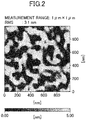
- FIG. 2 is an AFM image of the surface of the GaSb substrate 11 in this state. As illustrated in FIG. 2 , recesses and projections were created by removing the oxide film from the surface of the GaSb substrate 11 made of a semiconductor crystal. Surface roughness (RMS) of the GaSb substrate 11, from which the oxide film was removed, was measured and was 3.1 nm. The measurement range of the surface roughness (RMS) was 1 ⁇ m ⁇ 1 ⁇ m, which also applies to the GaSb layers described later.
- RMS Surface roughness
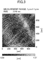
- FIG. 3 is an AFM image of the surface of the GaSb layer 12a formed in this way.
- Surface roughness (RMS) of the GaSb layer 12a was 0.16 nm.
- FIG. 4 is an AFM image of the surface of the GaSb layer 12b formed in this way.
- Surface roughness (RMS) of the GaSb layer 12b was 0.13 nm.
- the surface of the semiconductor crystal substrate can be made flat by forming the GaSb layer 12b. Accordingly, the surface roughness (RMS) of the GaSb layer 12b formed at the substrate temperature of 520 °C can become smaller than that of the GaSb layer 12a, allowing the surface of the semiconductor crystal substrate, which is the GaSb substrate, to be made flat.
- recesses such as pits are created on the surface of the GaSb layer 12b formed at the substrate temperature of 520 °C. Such pits are relatively deep, have a depth of several nm, and are present at a density of approximately 10 9 cm -2 .
- an infrared absorption layer with a T2SL structure is formed on the surface of the GaSb layer 12b having such pits, dislocation or a defect tends to be formed on the infrared absorption layer due to the pits. This may result in a decrease in light sensitivity or an increase in dark current of an infrared detector.
- the surface roughness of the GaSb layer 12a is larger than that of the GaSb layer 12b formed at the substrate temperature of 520 °C.
- conductivity of the GaSb layer 12a and conductivity of the GaSb layer 12b formed at the different substrate temperatures were examined. As a result, it was found that the GaSb layer 12a formed by MBE at the substrate temperature of 440 °C had n-type conductivity, and the GaSb layer 12b formed by MBE at the substrate temperature of 520 °C had p-type conductivity. Also, a carrier concentration in the GaSb layer 12a formed at the substrate temperature of 440 °C and a carrier concentration in the GaSb layer 12b formed at the substrate temperature of 520 °C were measured by a capacitance-voltage (CV) method.
- CV capacitance-voltage
- the carrier concentration in the GaSb layer 12a was approximately 4 ⁇ 10 18 cm -3
- the carrier concentration in the GaSb layer 12b was approximately 4 ⁇ 10 18 cm -3
- the GaSb layer 12a and the GaSb layer 12b were analyzed by secondary ion mass spectrometry (SIMS), and a concentration of an impurity element in each of the GaSb layer 12a and the GaSb layer 12b was less than or equal to 1 ⁇ 10 17 cm -3 .
- the substrate temperature is low, the removal of Sb from the formed GaSb layer is suppressed, and the amount of Sb contained in the GaSb layer 12a formed by MBE at the substrate temperature of 440 °C is thus slightly greater than the amount of Ga. Therefore, it is assumed that Sb partially enters a Ga site of a GaSb crystal and functions as a donor, and as a result, the GaSb layer 12a exhibits n-type conductivity. Also, when the substrate temperature is high, Sb tends to be readily removed from the formed GaSb layer, and the amount of Ga contained in the GaSb layer 12b formed by MBE at the substrate temperature of 520 °C is thus slightly greater than the amount of Sb. Therefore, it is assumed that Ga partially enters a Sb site of a GaSb crystal and functions as an acceptor, and as a result, the GaSb layer 12b exhibits p-type conductivity.
- the surface migration movement of Ga atoms becomes active.
- the substrate temperature is low, the surface migration movement of Ga atoms becomes less active. Accordingly, it is assumed that the migration distance of Ga atoms on the surface of the GaSb layer 12b formed at the substrate temperature of 520 °C becomes longer, and as a result, the surface of the GaSb layer 12b becomes flatter than the surface of the GaSb layer 12a formed at the substrate temperature of 440 °C, and also the surface roughness (RMS) of the GaSb layer 12b becomes smaller than that of the GaSb layer 12a.
- RMS surface roughness
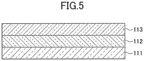
- a semiconductor crystal substrate according to the present embodiment includes a GaSb substrate 111, which is a crystal substrate, on which an n-type first GaSb layer 112 and a p-type second GaSb layer 113 are formed in this order.
- the first GaSb layer 112 is formed under the same condition as that of the GaSb layer 12a, namely is formed by MBE at the substrate temperature of 440 °C.
- the second GaSb layer 113 is formed under the same condition as that of the GaSb layer 12b, namely is formed by MBE at the substrate temperature of 520 °C.
- the GaSb substrate 111 is similar to the GaSb substrate 11.
- FIG. 6 is an AFM image of a surface of the second GaSb layer 113 formed on the first GaSb layer 112.
- the first GaSb layer 112 is formed on the GaSb substrate 111 after an oxide film is removed from the surface of the GaSb substrate 111.
- the first GaSb layer 112 is formed at the substrate temperature of 440 °C and has a thickness of 100 nm.
- the second GaSb layer 113 is formed at the substrate temperature of 520 °C and has a thickness of 400 nm.
- surface roughness (RMS) of the surface of the formed GaSb layer is 0.10 nm and the surface is flat. Also, pits as in illustrated in FIG. 4 are not formed.
- a possible reason why a film having a flat surface without pits can be obtained is because of a difference in surface migration lengths (diffusion lengths) of Ga atoms when substrate temperatures are different. Note that GaSb films are considered to grow in a step-flow mode at the substrate temperatures of both 440 °C and 520 °C.
- the substrate temperature is 520 °C
- the surface migration length of Ga atoms is long. Accordingly, as illustrated in FIG. 4 , while the flatness of a macroscopic surface can be improved, Ga atoms may fail to stably attach to microscopic recesses. As a result, pits tend to be formed.
- the substrate temperature is 440 °C
- the surface migration length of Ga atoms is short. Accordingly, as illustrated in FIG. 3 , while the flatness of a macroscopic surface is not sufficient, Ga atoms stably attach to microscopic recesses and the recesses are embedded. As a result, pits are not formed.
- GaSb film at the substrate temperature of 440 °C first, recesses of the uneven surface of the GaSb substrate 11 can be embedded. Subsequently, by forming a GaSb film at the substrate temperature of 520 °C, the surface of the GaSb film can be made flat. In this way, a film having a flat surface without pits can be obtained.
- the surface roughness (RMS) of the above GaSb film becomes 0.10 nm, which is smaller than the surface roughness (RMS) 0.16 nm of the GaSb layer 12b formed at the substrate temperature of 440 °C and the surface roughness (RMS) 0.13 nm of the GaSb layer 12a formed at the substrate temperature of 520 °C.
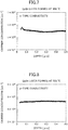
- FIG. 7 is a drawing illustrating a carrier concentration in the GaSb layer 12a formed at the substrate temperature of 440 °C.
- the carrier concentration was measured by the CV method while etching the GaSb layer 12a in a depth direction.
- the GaSb layer 12a formed at the substrate temperature of 440 °C exhibits n-type conductivity and the carrier concentration is approximately 4 ⁇ 10 18 cm -3 .
- FIG. 8 is a drawing illustrating a carrier concentration in the GaSb layer 12b formed at the substrate temperature of 520 °C.
- the carrier concentration was measured by the CV method while etching the GaSb layer 12b in the depth direction.
- the GaSb layer 12b formed at the substrate temperature of 520 °C exhibits p-type conductivity and the carrier concentration is approximately 4 ⁇ 10 18 cm -3 .
- a concentration of an impurity element in each of the first GaSb layer 112 and the second GaSb layer 113 is less than or equal to 1.0 ⁇ 10 17 cm -3 , similarly to that of the GaSb layer 12a and the GaSb layer 12b.
- the carrier concentration in the first GaSb layer 112 having n-type conductivity and the carrier concentration in the second GaSb layer 113 having p-type conductivity are preferably greater than or equal to 1.0 ⁇ 10 18 cm -3 and less than or equal to 1.0 ⁇ 10 20 cm -3 .
- the first GaSb layer 112 can be formed by solid source MBE at a substrate temperature greater than or equal to 380 °C and less than or equal to 440 °C. If the temperature were less than 380 °C, projections and recesses on the GaSb substrate 111 would not be sufficiently embedded because of an excessively long migration length of Ga atoms.
- the second GaSb layer 113 can be formed by solid source MBE at a substrate temperature greater than or equal to 500 °C and less than or equal to 550 °C, and more preferably at a substrate temperature greater than or equal to 520 °C and less than or equal to 550 °C.
- the semiconductor crystal substrate according to the present embodiment includes the GaSb substrate 111, which is a crystal substrate, on which the first GaSb layer 112 and the second GaSb layer 113 are formed in this order.
- the first GaSb layer 112 is rich in Sb and exhibits n-type conductivity.
- the second GaSb layer 113 is rich in Ga and exhibits p-type conductivity.
- the first GaSb layer 112 may be referred to as a first buffer layer and the second GaSb layer 113 may be referred to as a second buffer layer.
- the first buffer layer and the second buffer layer may be each formed of Ga 1-x In x As 1-y Sb y (0 ⁇ x ⁇ 0.1, 0 ⁇ y ⁇ 1). More specifically, the first buffer layer and the second buffer layer may be each formed of GaSb, or formed of GaInSb, GaAsSb, or GaInAsSb that is a material including GaSb and one or both of In and As.
- an exemplary method for producing a semiconductor crystal substrate according to the present embodiment will be described with reference to FIG. 9 .
- an n-type GaSb (001) substrate as a GaSb substrate 111 is placed in a vacuum chamber of a solid source molecular beam epitaxy (SSMBE) apparatus.
- the GaSb substrate 111 is heated by a heater.
- the substrate temperature of the GaSb substrate 111 reaches 400 °C
- the surface of the GaSb substrate 111 is irradiated with an Sb beam.
- the beam flux of Sb is, for example, 5.0 ⁇ 10 -7 torr.
- the GaSb substrate 111 When the GaSb substrate 111 is further heated, an oxide film of GaSb formed on the surface of the GaSb substrate 111 is removed at a substrate temperature of around 500 °C. Subsequently, the GaSb substrate 111 is heated up to a substrate temperature of 530 °C while being irradiated with the Sb beam, and is kept in this state for 20 minutes such that the oxide film of GaSb formed on the surface of the GaSb substrate 111 is completely removed.
- the substrate temperature of the GaSb substrate 111 is reduced to 440 °C in a state where the Sb beam is being emitted.
- a first GaSb layer 112 as a first buffer layer is formed on the GaSb substrate 111.
- a Ga beam is also emitted so as to form the first GaSb layer 112.
- the beam flux of Ga is, for example, 5.0 ⁇ 10 -8 torr, and the V/III ratio is 10. Under these conditions, the growth rate of the first GaSb layer 112 is 0.30 ⁇ m/h. Irradiation of the Ga beam is stopped after approximately 20 minutes when the thickness of the first GaSb layer 113 reaches 100 ⁇ m.
- the first GaSb layer 112 formed at the substrate temperature of 440 °C as described above has n-type conductivity.
- a second GaSb layer 113 as a second buffer layer is formed on the first GaSb layer 112 as the first buffer layer.
- the substrate temperature of the GaSb substrate 111 is raised to 520 °C in a state where the Sb beam is being emitted, and the Ga beam is emitted again so as to form the second GaSb layer 113.
- the beam flux of Ga is, for example, 5.0 ⁇ 10 -8 torr, and the V/III ratio is 10. Under these conditions, the growth rate of the second GaSb layer 113 is 0.30 ⁇ m/h. Irradiation of the Ga beam is stopped after approximately 80 minutes when the thickness of the second GaSb layer 113 reaches 400 ⁇ m.
- the second GaSb layer 113 formed at the substrate temperature of 520 °C as described above has p-type conductivity.
- the semiconductor crystal substrate according to the present embodiment can be produced.
- an n-type GaSb substrate is used as the GaSb substrate 111 in the present embodiment
- a p-type GaSb substrate may also be used as the GaSb substrate 111.
- the plane direction of the GaSb substrate 111 is not limited to (001), and an off-substrate may also be used as the GaSb substrate 111.
- an InAs substrate may be used in place of the GaSb substrate 111.
- the first buffer layer may include an element isolation layer such that electric crosstalk can be prevented in an array-type device such as a semiconductor laser or an infrared detector.
- FIG. 10 is a structural drawing illustrating the entire structure of an infrared detector according to the second embodiment.
- FIG. 11 illustrates a structure in which one pixel of the infrared detector is enlarged.
- a first GaSb layer 112, a second GaSb layer 113, a p-type contact layer 114, an infrared absorption layer 115, and an n-type contact layer 116 are stacked in this order on a GaSb substrate 111.
- the GaSb substrate 111 is an n-type GaSb (001) substrate
- the first GaSb layer 112 has a thickness of approximately 100 nm
- the second GaSb layer 113 has a thickness of approximately 400 nm.
- the p-type contact layer 114 is a p-type GaSb layer that has a thickness of 500 nm and is doped with Be as an impurity element.
- the infrared absorption layer 115 has an InAs/GaSb superlattice (T2SL) structure.
- T2SL InAs/GaSb superlattice
- the infrared absorption layer 115 is formed by alternately stacking an InAs layer with a thickness of approximately 2 nm and a GaSb layer with a thickness of approximately 2 nm, such that the infrared absorption layer 115 includes 200 pairs of the InAs layer and the GaSb layer and has a thickness of approximately 800 nm.
- the n-type contact layer 116 is an n-type InAs layer that has a thickness of approximately 30 nm and is doped with Si as an impurity element.
- the p-type contact layer 114 may be referred to as a first contact layer
- the n-type contact layer 116 may be referred to as a second contact layer.
- pixel separating grooves 120 for separating pixels are formed in the n-type contact layer 116 and the infrared absorption layer 115.
- a passivation film 131 composed of SiN is formed on the side surfaces and the bottom surfaces of the pixel separating grooves 120.
- multiple pixels separated by the pixel separating grooves 120 are arranged two-dimensionally.
- An electrode 141 is formed on the n-type contact layer 116 of each of the pixels separated by the pixel separating grooves 120, and an electrode 142 is formed on the p-type contact layer 114. In the vicinity of the electrode 142, a wiring support 143 is configured by the infrared absorption layer 115 and the n-type contact layer 116.
- a wiring layer 144 is formed so as to extend from the electrode 142 via the side surface of the wiring support 143 to the upper surface of the wiring support 143. Accordingly, the infrared absorption layer 115 and the n-type contact layer 116 forming the wiring support 143 are not used for infrared detection.
- the electrodes 141 and 142 are formed of a metal laminated film made of Ti, Pt, and Au.
- a device configured as described above may be referred to as an infrared detector or an infrared detecting device 150.
- the infrared detector according to the present embodiment can detect infrared radiation incident from the back surface of the GaSb substrate 111.
- a signal readout circuit device 160 is connected to the infrared detecting device 150.
- bumps 145 are formed on the electrodes 141 of the infrared detecting device 150
- a bump 146 is formed on the wiring layer 144 of the infrared detecting device 150.
- the signal readout circuit device 160 includes a circuit board 161 on which a signal readout circuit is formed. Electrodes 162 are formed on the circuit board 161, and bumps 163 are formed on the electrodes 162. The bumps 145 and 146 and the bumps 163 are disposed facing each other.
- the infrared detecting device 150 and the signal readout circuit device 160 are connected to each other by connecting the bumps 145 and 146 to the corresponding bumps 163.
- FIG. 12 is a perspective view of the infrared detector according to the present embodiment.
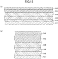
- FIGS. 13 (a) , 14(a) , 15(a) , and 16(a) each illustrate a structure involved in a corresponding process
- FIGS. 13 (b) , 14(b) , 15 (b) , and 16(b) each illustrate an enlarged part corresponding to one pixel.
- the first GaSb layer 112, the second GaSb layer 113, a p-type contact layer 114, the infrared absorption layer 115, and the n-type contact layer 116 are formed in this order on the GaSb substrate 111 by MBE epitaxial growth.
- a structure obtained by sequentially forming the first GaSb layer 112 and the second GaSb layer 113 on the GaSb substrate 111 corresponds to the semiconductor crystal substrate according to the first embodiment. Therefore, detailed descriptions of the GaSb substrate 111, the first GaSb layer 112, and the second GaSb layer 113 will be omitted.
- the first GaSb layer 112 and the second GaSb layer 113 are sequentially formed on the GaSb substrate 111, and the p-type contact layer 114 is formed on the second GaSb layer 113.
- the p-type contact layer 114 is a p-type GaSb layer that is formed by emitting Ga, Sb, and Be beams at a substrate temperature of 520 °C. At this time, the temperature of a Be cell is adjusted such that the concentration of Be, which is an impurity element used as a dopant of the p-type contact layer 114, becomes 5.0 ⁇ 10 18 cm -3 .
- the beam flux of Ga is 5.0 ⁇ 10 -8 torr
- the beam flux of Sb is 5.0 ⁇ 10 -7 torr
- the V/III ratio is 10.
- the growth rate of GaSb is 0.30 ⁇ m/h. Irradiation of the Be and Ga beams is stopped after approximately 100 minutes when the thickness of the p-type contact layer 114 reaches 500 ⁇ m.
- the infrared absorption layer 115 with an InAs/GaSb superlattice structure is formed on the p-type contact layer 114.
- the substrate temperature of the GaSb substrate 111 is reduced to 440 °C.
- irradiation of the Sb beam is stopped and In and As beams are emitted.
- the beam flux of In is 5.0 ⁇ 10 -8 torr
- the beam flux of As is 5.0 ⁇ 10 -7 torr
- the V/III ratio is 10. Under these conditions, the growth rate of InAs is 0.30 ⁇ m/h.
- Irradiation of the In and As beams is stopped after approximately 36 seconds when the thickness of an InAs layer reaches 2 ⁇ m.
- Ga and Sb beams are emitted.
- the beam flux of Ga is 5.0 ⁇ 10 -8 torr
- the beam flux of Sb is 5.0 ⁇ 10 -7 torr
- the V/III ratio is 10.
- the growth rate of GaSb is 0.30 ⁇ m/h.
- Irradiation of the Ga and Sb beams is stopped after approximately 36 seconds when the thickness of a GaSb layer reaches 2 ⁇ m. After an interval of three seconds, the above process is repeated.
- the cycle is repeated 200 times such that the infrared absorption layer 115 with a total thickness of approximately 800 nm is formed.
- the n-type contact layer 116 is formed on the infrared absorption layer 115.
- the n-type contact layer 116 is an n-type InAs layer that is formed by emitting In, As, and Si beams.
- the temperature of a Si cell is adjusted such that the concentration of Si, which is an impurity element used as a dopant of the n-type contact layer 116, becomes 5.0 ⁇ 10 18 cm -3 .
- the beam flux of In is 5.0 ⁇ 10 -8 torr
- the beam flux of As is 5.0 ⁇ 10 -7 torr
- the V/III ratio is 10. Under these conditions, the growth rate of InAs is 0.30 ⁇ m/h. Irradiation of the In and Si beams is stopped after approximately 6 minutes when the thickness of an InAs layer reaches 30 ⁇ m.
- the substrate temperature is reduced to 400 °C. Then, irradiation of the As beam is stopped, and a structure where epitaxial films are formed on the GaSb substrate 111 is taken out from the vacuum chamber of the MBE apparatus.
- portions of the n-type contact layer 116 and the infrared absorption layer 115 are removed so as to form pixel separating grooves 120.
- a photoresist is applied to the n-type contact layer 116, and the photoresist is exposed and developed by an exposure apparatus so as to form a resist pattern (not illustrated) having openings in areas where the pixel separating grooves 120 are to be formed.
- portions of the n-type contact layer 116 and the infrared absorption layer 115 in the areas not covered by the resist pattern are removed by dry etching using CF 4 gas. As a result, the pixel separating grooves 120 are formed.
- pixels having mesa structures and separated by the pixel separating grooves 120 are formed.
- the size of one pixel is 50 ⁇ m ⁇ 50 ⁇ m, and 256 ⁇ 256 pixels are formed in the infrared detector.
- the passivation film 131 is formed on the upper surface of the n-type contact layer 116, on the side surfaces of the n-type contact layer 116 and the infrared absorption layer 115, which form the pixels, and on the upper surface of the p-type contact layer 114 between the pixels.
- the passivation film 131 is an SiN film with a thickness of 100 nm and is formed by plasma chemical vapor deposition (CVD) using SiH 4 gas and NH 3 gas.
- a photoresist is applied, and the photoresist is exposed and developed by an exposure apparatus so as to form a resist pattern (not illustrated) having openings in areas where the electrodes 141 and 142 are to be formed.
- portions of the passivation film 131 in the areas not covered by the resist pattern are removed by dry etching using CF 4 gas such that the n-type contact layer 116 and the p-type contact layer 114 in those areas are exposed.
- the electrodes 141 are formed on the exposed portions of the n-type contact layer 116 and the electrode 142 is formed on the exposed portion of the p-type contact layer 114.
- a resist pattern (not illustrated) is formed, which has openings in areas where the electrodes 141 and 142 are to be formed.
- a metal laminated film made of Ti, Pt, and Au is formed by vacuum deposition or sputtering. After immersion in an organic solvent, for example, the metal multilayer film formed on the resist pattern is removed by a lift-off technique, together with the resist pattern. The remaining portions of the metal multilayer film form the electrodes 141 on the n-type contact layer 116 and form the electrode 142 on the p-type contact layer 114.
- the wiring layer 144 is formed on the electrode 142 and the side surface and the upper surface of the wiring support 143. Also, the bumps 145 are formed on the electrodes 141, and the bump 146 is formed on the wiring layer 144 above the wiring support 143. The formed bumps 145 and 146 are connected to the bumps 163 of the signal readout circuit device 160 by flip-chip bonding. As a result, the infrared detecting device 150 and the signal readout circuit device 160 are connected to each other.
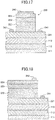
- FIG. 17 illustrates a configuration of a semiconductor laser according to the third embodiment.
- the semiconductor laser according to the present embodiment uses the semiconductor crystal substrate according to the first embodiment in which the first GaSb layer 112 and the second GaSb layer 113 are formed on the GaSb substrate 111.
- a p-type GaSb cladding layer 221, a multi-quantum well (MQW) layer 222, an n-type GaSb cladding layer 223, and an n-type InAs layer 224 are formed in this order on the second GaSb layer 113.
- the p-type GaSb cladding layer 221 has a thickness of approximately 500 nm and is doped with Be as a p-type impurity element.
- the MQW layer 222 is a light emitting layer having a multi-quantum well structure in which a GaSb layer with a thickness of approximately 5 nm and an InAs layer with a thickness of approximately 5 nm are alternately formed.
- the MQW layer 222 includes 20 pairs of the GaSb layer and the InAs layer.
- the n-type GaSb cladding layer 223 has a thickness of approximately 100 nm, is doped with Si as an n-type impurity element, and has a carrier concentration of 5.0 ⁇ 10 18 cm -3 .
- the n-type InAs layer 224 has a thickness of approximately 30 nm.
- portions of the n-type InAs layer 224, the n-type GaSb cladding layer 223, and the MQW layer 222 are removed so as to form a mesa structure 230.
- portions of the n-type InAs layer 224, the n-type GaSb cladding layer 223, and the MQW layer 222 are removed by dry etching using CF 4 gas as an etching gas such that portions of the p-type GaSb cladding layer 221 are exposed and thereby a mesa structure 230 is formed.
- lower electrodes 241 are formed on the exposed portions of the p-type GaSb cladding layer 221, and an upper electrode 242 is formed on the n-type InAs layer 224.
- the lower electrodes 241 and the upper electrode 242 are each formed of a metal multilayer film made of Ti, Pt, and Au, for example.
- the GaSb substrate 111 is cleaved so as to be formed in a stripe shape having a width of 20 ⁇ m and a length of 50 ⁇ m.
- the semiconductor laser according to the present embodiment can be produced.
- the semiconductor laser is an edge emitting laser with a wavelength of 3.0 ⁇ m.
- FIG. 18 illustrates a configuration of a light emitting diode according to the present embodiment.
- the light emitting diode according to the fourth embodiment uses the semiconductor crystal substrate according to the first embodiment. After layers similarly to those of the third embodiment are formed by MBE epitaxial growth, a lower electrode 241 and an upper electrode 242 are formed.
- the GaSb substrate 111 is cleaved so as to be formed in a chip shape having a width of 50 ⁇ m and a length of 50 ⁇ m.
- the light emitting diode according to the present embodiment can be produced. Because the light emitting diode emits light from the side on which the n-type InAs layer 224 is formed, an area of the n-type InAs layer 224 where the upper electrode 242 is not formed is preferably as large as possible.
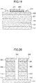
- FIG. 19 illustrates a configuration of a field-effect transistor according to the present embodiment.
- the field effect transistor according to the fifth embodiment uses the semiconductor crystal substrate according to the first embodiment in which the first GaSb layer 112 and the second GaSb layer 113 are formed on the GaSb substrate 111.
- An Al 0.8 Ga 0.2 Sb layer 251 and a channel layer 252 are formed by MBE on the second GaSb layer 113.
- the Al 0.8 Ga 0.2 Sb layer 251 has a thickness of approximately 200 nm.
- the channel layer 252 is a p-type In 0.2 Ga 0.8 Sb layer with a thickness of 5 nm, is doped with Be as a p-type impurity element, and has a carrier concentration of 5.0 ⁇ 10 18 cm -3 .
- an insulating film 260 is formed by atomic layer deposition (ALD) on the channel layer 252.
- the insulating film 260 is an Al 2 O 3 film with a thickness of 3 nm.
- a gate electrode 271 is formed on the insulating film 260, and a source electrode 272 and a drain electrode 273 are formed on the channel layer 252.
- the gate electrode 271 may be a tungsten (W) film with a thickness of approximately 100 nm, and may be formed by CVD on the insulating layer 260.
- the gate electrode 271 is formed so as to have a gate length of 30 nm.
- portions of the insulating film 260 which correspond to areas where the source electrode 272 and the drain electrode 273 are to be formed, are removed.
- the source electrode 272 and the drain electrode 273 are formed with, for example, Ni films.
- the field-effect transistor according to the present embodiment can be produced.
- thermoelectric transducer produced by using the semiconductor crystal substrate according to the first embodiment will be described.
- thermoelectric transducer according to the present embodiment will be described.
- thermoelectric transducer uses the semiconductor crystal substrate according to the first embodiment in which the first GaSb layer 112 and the second GaSb layer 113 are formed on the GaSb substrate 111.
- a superlattice layer 280 and a cap layer 281 are sequentially formed by MBE on the second GaSb layer 113.
- the superlattice layer 280 is formed by alternately stacking a GaSb layer with a thickness of approximately 5 nm and an InAs layer with a thickness of approximately 5 nm.
- the superlattice layer 280 includes 500 pairs of the GaSb layer and the InAs layer.
- the cap layer 281 is a non-doped InAs film with a thickness of 30 nm.
- portions of the cap layer 281, the superlattice layer 280, the second GaSb layer 113, and the first GaSb layer 112 are removed so as to form mesa structures 282.
- portions of the cap layer 281, the superlattice layer 280, the second GaSb layer 113, and the first GaSb layer 112 are removed by dry etching using CF 4 gas as an etching gas so as to form mesa structures 282.
- FIG. 20 illustrates the structures.
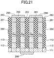
- a SiO 2 film 283 is formed by CVD such that a gap between the mesa structures 282 is filled.
- the back surface of the GaSb substrate 111 is polished by chemical mechanical polishing (CMP) so as to reduce the thickness of the GaSb substrate 111 to approximately 3 ⁇ m.
- CMP chemical mechanical polishing
- impurity ions used as n-type and p-type dopants are ion-implanted into the mesa structures 282 and activation annealing is performed so as to form n-type regions (n-type elements) and p-type regions (p-type elements).
- electrodes 290 are formed on both sides such that the n-type elements and the p-type elements are connected in series.
- Each of the electrodes 290 is formed of a metal multilayer film made of Ti, Pt, and Au, for example.
Landscapes
- Physics & Mathematics (AREA)
- General Physics & Mathematics (AREA)
- Spectroscopy & Molecular Physics (AREA)
- Condensed Matter Physics & Semiconductors (AREA)
- Electromagnetism (AREA)
- Optics & Photonics (AREA)
- Manufacturing & Machinery (AREA)
- Engineering & Computer Science (AREA)
- Inorganic Chemistry (AREA)
- Chemical & Material Sciences (AREA)
- Geometry (AREA)
- Physical Deposition Of Substances That Are Components Of Semiconductor Devices (AREA)
- Light Receiving Elements (AREA)
- Recrystallisation Techniques (AREA)
- Physical Vapour Deposition (AREA)
- Solid State Image Pick-Up Elements (AREA)
Abstract
Description
- The disclosures herein relate to a semiconductor crystal substrate, an infrared detector, a photosemiconductor device, a semiconductor device, a thermoelectric transducer, a method for producing the semiconductor crystal substrate, and a method for producing the infrared detector.
- As an apparatus for detecting infrared, there are infrared detectors formed of semiconductor materials. Examples of such infrared detectors include an infrared detector that has a structure in which an infrared absorption layer with an InAs/GaSb superlattice structure is formed on a GaSb substrate. The InAs/GaSb superlattice structure forming the infrared absorption layer is a type-II superlattice (T2SL) structure and has a type-II band lineup. Accordingly, by adjusting the film thickness and the period of the superlattice of the InAs/GaSb superlattice structure, it is possible to obtain an infrared detector that is sensitive in a wavelength range from a middle wave (MW) infrared of 3 to 5 µm to a long wave (LW) infrared of 8 to 10 µm.
- A PIN-type infrared detector with a T2SL structure uses inter-band optical absorption. For this reason, a PIN-type infrared detector with a T2SL structure is expected to have improved temperature characteristics as compared to a quantum dot infrared photodetector (QDIP) and a quantum well infrared photodetector (QWIP) that use inter-subband optical absorption. In such a PIN-type infrared detector with a T2SL structure, it is desirable to have high light sensitivity and low dark current in addition to improved temperature characteristics.
- In order to obtain high light sensitivity and low dark current in a PIN-type infrared detector with a T2SL structure, a high-quality T2SL crystal needs to be formed in an infrared absorption layer, and in order to form the high-quality T2SL crystal, a GaSb buffer layer with high flatness needs to be formed below the infrared absorption layer. For example, Non-Patent
Document 1 proposes improving the quality of a GaSb buffer layer by changing a growth temperature and a V/III ratio in a molecular beam epitaxy (MBE) method. To be more specific,Non-Patent Document 1 discloses that an excellent GaSb layer can be obtained by epitaxially growing the GaSb layer at a growth temperature of 500 °C to 550 °C and a V/III ratio of 5 to 10. -
- [Patent Document 1] Japanese Laid-open Patent Publication No.
5-299358 - [Patent Document 2] Japanese National Publication of International Patent Application No.
2015-512139 - [Non-Patent Document 1] M. Lee et al., Journal of Applied Physics 59, 2895 (1986).
- However, it is not possible to obtain a high-quality T2SL crystal that fully satisfies desired characteristics of an infrared absorption layer by merely changing conditions under which a GaSb buffer layer is formed. Accordingly, there is a demand for a semiconductor crystal substrate including a GaSb buffer layer with high surface flatness.
- According to an aspect of at least one embodiment, a semiconductor crystal substrate includes a crystal substrate that is formed of a material including GaSb or InAs; a first buffer layer that is formed on the crystal substrate and formed of a material including GaSb, the first buffer layer having n-type conductivity; and a second buffer layer that is formed on the first buffer layer and formed of a material including GaSb, the second buffer layer having p-type conductivity.
- According to a semiconductor crystal substrate disclosed herein, a GaSb layer with high surface flatness can be provided.
-
-
FIG. 1 is a structural drawing illustrating a semiconductor crystal substrate including a GaSb substrate on which a GaSb layer is formed; -
FIG. 2 is an AFM image of a surface of the GaSb substrate; -
FIG. 3 is an AFM image of a GaSb layer formed on the GaSb substrate at a substrate temperature of 440 °C; -
FIG. 4 is an AFM image of a GaSb layer formed on the GaSb substrate at a substrate temperature of 520 °C; -
FIG. 5 is a structural drawing illustrating a semiconductor crystal substrate according to a first embodiment; -
FIG. 6 is an AFM image of a GaSb layer formed on the semiconductor crystal substrate according to the first embodiment; -
FIG. 7 is a drawing illustrating a carrier concentration in the GaSb layer formed at a substrate temperature of 440 °C; -
FIG. 8 is a drawing illustrating a carrier concentration in the GaSb layer formed at a substrate temperature of 520 °C; -
FIG. 9 is a drawing illustrating a method for producing a semiconductor crystal substrate according to the first embodiment; -
FIG. 10 is a structural drawing illustrating an infrared detector according to a second embodiment; -
FIG. 11 is a structural drawing illustrating a main part of the infrared detector according to a second embodiment; -
FIG. 12 is a perspective view of the infrared detector according to the second embodiment; -
FIG. 13 is a drawing illustrating a process (1) of a method for producing a semiconductor crystal substrate according to the second embodiment; -
FIG. 14 is a drawing illustrating a process (2) of the method for producing the semiconductor crystal substrate according to the second embodiment; -
FIG. 15 is a drawing illustrating a process (3) of the method for producing the semiconductor crystal substrate according to the second embodiment; -
FIG. 16 is a drawing illustrating a process (4) of the method for producing the semiconductor crystal substrate according to the second embodiment; -
FIG. 17 is a structural drawing illustrating a semiconductor laser according to a third embodiment; -
FIG. 18 is a structural drawing illustrating a light emitting diode according to a fourth embodiment; -
FIG. 19 is a structural drawing illustrating a field-effect transistor according to a fifth embodiment; -
FIG. 20 is a drawing (1) illustrating a thermoelectric transducer according to a sixth embodiment; and -
FIG. 21 is a drawing (2) illustrating the thermoelectric transducer according to the sixth embodiment. - In the following, embodiments of the present invention will be described with reference to the accompanying drawings. The same components are denoted by the same reference numerals throughout the drawings, and a duplicate description thereof will be omitted.
- First, a relationship between film forming conditions and flatness of a GaSb film was investigated. To be more specific, as illustrated in
FIG. 1 , aGaSb layer 12a and aGaSb layer 12b were each formed on aGaSb substrate 11 under different film forming conditions so as to prepare a semiconductor crystal substrate, and flatness of surfaces of theGaSb layer 12a and theGaSb layer 12b was measured. The flatness of the surfaces of theGaSb layer 12a and theGaSb layer 12b was measured by an atomic force microscope (AFM). Each of theGaSb layer 12a and theGaSb layer 12b was formed by solid source molecular-beam epitaxy (MBE) at a V/III ratio of approximately 10. - An oxide film formed by oxidation on the surface of the
GaSb substrate 11 was removed by heating theGaSb substrate 11 at a temperature of approximately 500 °C under vacuum.FIG. 2 is an AFM image of the surface of theGaSb substrate 11 in this state. As illustrated inFIG. 2 , recesses and projections were created by removing the oxide film from the surface of theGaSb substrate 11 made of a semiconductor crystal. Surface roughness (RMS) of theGaSb substrate 11, from which the oxide film was removed, was measured and was 3.1 nm. The measurement range of the surface roughness (RMS) was 1 µm × 1 µm, which also applies to the GaSb layers described later. - Next, at a substrate temperature of 440 °C, the
GaSb layer 12a with a thickness of 500 nm was formed by MBE on theGaSb substrate 11 from which the oxide film was removed.FIG. 3 is an AFM image of the surface of theGaSb layer 12a formed in this way. Surface roughness (RMS) of theGaSb layer 12a was 0.16 nm. - Meanwhile, at a substrate temperature of 520 °C, the
GaSb layer 12b with a thickness of 500 nm was formed by MBE on theGaSb substrate 11 from which the oxide film was removed.FIG. 4 is an AFM image of the surface of theGaSb layer 12b formed in this way. Surface roughness (RMS) of theGaSb layer 12b was 0.13 nm. Thus, the surface of the semiconductor crystal substrate can be made flat by forming theGaSb layer 12b. Accordingly, the surface roughness (RMS) of theGaSb layer 12b formed at the substrate temperature of 520 °C can become smaller than that of theGaSb layer 12a, allowing the surface of the semiconductor crystal substrate, which is the GaSb substrate, to be made flat. - As illustrated in
FIG. 4 , recesses such as pits are created on the surface of theGaSb layer 12b formed at the substrate temperature of 520 °C. Such pits are relatively deep, have a depth of several nm, and are present at a density of approximately 109 cm-2. When an infrared absorption layer with a T2SL structure is formed on the surface of theGaSb layer 12b having such pits, dislocation or a defect tends to be formed on the infrared absorption layer due to the pits. This may result in a decrease in light sensitivity or an increase in dark current of an infrared detector. - Conversely, as illustrated in
FIG. 3 , while pits are not created on the surface of theGaSb layer 12a formed at the substrate temperature of 440 °C, the surface roughness of theGaSb layer 12a is larger than that of theGaSb layer 12b formed at the substrate temperature of 520 °C. - Next, conductivity of the
GaSb layer 12a and conductivity of theGaSb layer 12b formed at the different substrate temperatures were examined. As a result, it was found that theGaSb layer 12a formed by MBE at the substrate temperature of 440 °C had n-type conductivity, and theGaSb layer 12b formed by MBE at the substrate temperature of 520 °C had p-type conductivity. Also, a carrier concentration in theGaSb layer 12a formed at the substrate temperature of 440 °C and a carrier concentration in theGaSb layer 12b formed at the substrate temperature of 520 °C were measured by a capacitance-voltage (CV) method. The carrier concentration in theGaSb layer 12a was approximately 4 × 1018 cm-3, and the carrier concentration in theGaSb layer 12b was approximately 4 × 1018 cm-3. Further, theGaSb layer 12a and theGaSb layer 12b were analyzed by secondary ion mass spectrometry (SIMS), and a concentration of an impurity element in each of theGaSb layer 12a and theGaSb layer 12b was less than or equal to 1 × 1017 cm-3. - Accordingly, when the substrate temperature is low, the removal of Sb from the formed GaSb layer is suppressed, and the amount of Sb contained in the
GaSb layer 12a formed by MBE at the substrate temperature of 440 °C is thus slightly greater than the amount of Ga. Therefore, it is assumed that Sb partially enters a Ga site of a GaSb crystal and functions as a donor, and as a result, theGaSb layer 12a exhibits n-type conductivity. Also, when the substrate temperature is high, Sb tends to be readily removed from the formed GaSb layer, and the amount of Ga contained in theGaSb layer 12b formed by MBE at the substrate temperature of 520 °C is thus slightly greater than the amount of Sb. Therefore, it is assumed that Ga partially enters a Sb site of a GaSb crystal and functions as an acceptor, and as a result, theGaSb layer 12b exhibits p-type conductivity. - When the substrate temperature during the formation of a GaSb layer is high, the surface migration movement of Ga atoms becomes active. On the other hand, when the substrate temperature is low, the surface migration movement of Ga atoms becomes less active. Accordingly, it is assumed that the migration distance of Ga atoms on the surface of the
GaSb layer 12b formed at the substrate temperature of 520 °C becomes longer, and as a result, the surface of theGaSb layer 12b becomes flatter than the surface of theGaSb layer 12a formed at the substrate temperature of 440 °C, and also the surface roughness (RMS) of theGaSb layer 12b becomes smaller than that of theGaSb layer 12a. - A semiconductor crystal substrate according to the present embodiment is obtained based on the above-described findings. As illustrated in
FIG. 5 , a semiconductor crystal substrate according to the present embodiment includes aGaSb substrate 111, which is a crystal substrate, on which an n-typefirst GaSb layer 112 and a p-typesecond GaSb layer 113 are formed in this order. To be more specific, thefirst GaSb layer 112 is formed under the same condition as that of theGaSb layer 12a, namely is formed by MBE at the substrate temperature of 440 °C. Also, thesecond GaSb layer 113 is formed under the same condition as that of theGaSb layer 12b, namely is formed by MBE at the substrate temperature of 520 °C. Further, theGaSb substrate 111 is similar to theGaSb substrate 11. -
FIG. 6 is an AFM image of a surface of thesecond GaSb layer 113 formed on thefirst GaSb layer 112. Thefirst GaSb layer 112 is formed on theGaSb substrate 111 after an oxide film is removed from the surface of theGaSb substrate 111. Thefirst GaSb layer 112 is formed at the substrate temperature of 440 °C and has a thickness of 100 nm. Thesecond GaSb layer 113 is formed at the substrate temperature of 520 °C and has a thickness of 400 nm. As illustrated inFIG. 6 , surface roughness (RMS) of the surface of the formed GaSb layer is 0.10 nm and the surface is flat. Also, pits as in illustrated inFIG. 4 are not formed. - A possible reason why a film having a flat surface without pits can be obtained is because of a difference in surface migration lengths (diffusion lengths) of Ga atoms when substrate temperatures are different. Note that GaSb films are considered to grow in a step-flow mode at the substrate temperatures of both 440 °C and 520 °C.
- Namely, when the substrate temperature is 520 °C, the surface migration length of Ga atoms is long. Accordingly, as illustrated in
FIG. 4 , while the flatness of a macroscopic surface can be improved, Ga atoms may fail to stably attach to microscopic recesses. As a result, pits tend to be formed. - Conversely, when the substrate temperature is 440 °C, the surface migration length of Ga atoms is short. Accordingly, as illustrated in
FIG. 3 , while the flatness of a macroscopic surface is not sufficient, Ga atoms stably attach to microscopic recesses and the recesses are embedded. As a result, pits are not formed. - Therefore, by forming a GaSb film at the substrate temperature of 440 °C first, recesses of the uneven surface of the
GaSb substrate 11 can be embedded. Subsequently, by forming a GaSb film at the substrate temperature of 520 °C, the surface of the GaSb film can be made flat. In this way, a film having a flat surface without pits can be obtained. Accordingly, it is assumed that the surface roughness (RMS) of the above GaSb film becomes 0.10 nm, which is smaller than the surface roughness (RMS) 0.16 nm of theGaSb layer 12b formed at the substrate temperature of 440 °C and the surface roughness (RMS) 0.13 nm of theGaSb layer 12a formed at the substrate temperature of 520 °C. -
FIG. 7 is a drawing illustrating a carrier concentration in theGaSb layer 12a formed at the substrate temperature of 440 °C. The carrier concentration was measured by the CV method while etching theGaSb layer 12a in a depth direction. As illustrated, theGaSb layer 12a formed at the substrate temperature of 440 °C exhibits n-type conductivity and the carrier concentration is approximately 4 × 1018 cm-3. -
FIG. 8 is a drawing illustrating a carrier concentration in theGaSb layer 12b formed at the substrate temperature of 520 °C. The carrier concentration was measured by the CV method while etching theGaSb layer 12b in the depth direction. As illustrated, theGaSb layer 12b formed at the substrate temperature of 520 °C exhibits p-type conductivity and the carrier concentration is approximately 4 × 1018 cm-3. - Also, a concentration of an impurity element in each of the
first GaSb layer 112 and thesecond GaSb layer 113 is less than or equal to 1.0 × 1017 cm-3, similarly to that of theGaSb layer 12a and theGaSb layer 12b. - In the present embodiment, the carrier concentration in the
first GaSb layer 112 having n-type conductivity and the carrier concentration in thesecond GaSb layer 113 having p-type conductivity are preferably greater than or equal to 1.0 × 1018 cm-3 and less than or equal to 1.0 × 1020 cm-3. Thefirst GaSb layer 112 can be formed by solid source MBE at a substrate temperature greater than or equal to 380 °C and less than or equal to 440 °C. If the temperature were less than 380 °C, projections and recesses on theGaSb substrate 111 would not be sufficiently embedded because of an excessively long migration length of Ga atoms. Also, thesecond GaSb layer 113 can be formed by solid source MBE at a substrate temperature greater than or equal to 500 °C and less than or equal to 550 °C, and more preferably at a substrate temperature greater than or equal to 520 °C and less than or equal to 550 °C. - As described above, the semiconductor crystal substrate according to the present embodiment includes the
GaSb substrate 111, which is a crystal substrate, on which thefirst GaSb layer 112 and thesecond GaSb layer 113 are formed in this order. Thefirst GaSb layer 112 is rich in Sb and exhibits n-type conductivity. Thesecond GaSb layer 113 is rich in Ga and exhibits p-type conductivity. In the present application, thefirst GaSb layer 112 may be referred to as a first buffer layer and thesecond GaSb layer 113 may be referred to as a second buffer layer. - Also in the present embodiment, the first buffer layer and the second buffer layer may be each formed of Ga1-xInxAs1-ySby (0 ≤ x ≤ 0.1, 0 ≤ y < 1). More specifically, the first buffer layer and the second buffer layer may be each formed of GaSb, or formed of GaInSb, GaAsSb, or GaInAsSb that is a material including GaSb and one or both of In and As.
- Next, an exemplary method for producing a semiconductor crystal substrate according to the present embodiment will be described with reference to
FIG. 9 . First, as illustrated inFIG. 9 (a) , an n-type GaSb (001) substrate as aGaSb substrate 111 is placed in a vacuum chamber of a solid source molecular beam epitaxy (SSMBE) apparatus. Next, theGaSb substrate 111 is heated by a heater. When the substrate temperature of theGaSb substrate 111reaches 400 °C, the surface of theGaSb substrate 111 is irradiated with an Sb beam. The beam flux of Sb is, for example, 5.0 × 10⁻⁷ torr. When theGaSb substrate 111 is further heated, an oxide film of GaSb formed on the surface of theGaSb substrate 111 is removed at a substrate temperature of around 500 °C. Subsequently, theGaSb substrate 111 is heated up to a substrate temperature of 530 °C while being irradiated with the Sb beam, and is kept in this state for 20 minutes such that the oxide film of GaSb formed on the surface of theGaSb substrate 111 is completely removed. - Next, as illustrated in
FIG. 9 (b) , the substrate temperature of theGaSb substrate 111 is reduced to 440 °C in a state where the Sb beam is being emitted. Then, afirst GaSb layer 112 as a first buffer layer is formed on theGaSb substrate 111. To be more specific, in a state where theGaSb substrate 111 is at the substrate temperature of 440 °C and the Sb beam is being emitted, a Ga beam is also emitted so as to form thefirst GaSb layer 112. The beam flux of Ga is, for example, 5.0 × 10⁻⁸ torr, and the V/III ratio is 10. Under these conditions, the growth rate of thefirst GaSb layer 112 is 0.30 µm/h. Irradiation of the Ga beam is stopped after approximately 20 minutes when the thickness of thefirst GaSb layer 113 reaches 100 µm. Thefirst GaSb layer 112 formed at the substrate temperature of 440 °C as described above has n-type conductivity. - Next, as illustrated in
FIG. 9 (c) , asecond GaSb layer 113 as a second buffer layer is formed on thefirst GaSb layer 112 as the first buffer layer. To be more specific, the substrate temperature of theGaSb substrate 111 is raised to 520 °C in a state where the Sb beam is being emitted, and the Ga beam is emitted again so as to form thesecond GaSb layer 113. The beam flux of Ga is, for example, 5.0 × 10⁻⁸ torr, and the V/III ratio is 10. Under these conditions, the growth rate of thesecond GaSb layer 113 is 0.30 µm/h. Irradiation of the Ga beam is stopped after approximately 80 minutes when the thickness of thesecond GaSb layer 113reaches 400 µm. Thesecond GaSb layer 113 formed at the substrate temperature of 520 °C as described above has p-type conductivity. - In this way, the semiconductor crystal substrate according to the present embodiment can be produced. Although an n-type GaSb substrate is used as the
GaSb substrate 111 in the present embodiment, a p-type GaSb substrate may also be used as theGaSb substrate 111. Also, the plane direction of theGaSb substrate 111 is not limited to (001), and an off-substrate may also be used as theGaSb substrate 111. Further, an InAs substrate may be used in place of theGaSb substrate 111. - Also, as a two-layer structure of the n-type first buffer layer and the p-type second buffer layer is formed, the first buffer layer may include an element isolation layer such that electric crosstalk can be prevented in an array-type device such as a semiconductor laser or an infrared detector.
- Next, a second embodiment will be described. In the second embodiment, an infrared detector produced by using the semiconductor crystal substrate according to the first embodiment will be described.
FIG. 10 is a structural drawing illustrating the entire structure of an infrared detector according to the second embodiment.FIG. 11 illustrates a structure in which one pixel of the infrared detector is enlarged. - As illustrated in
FIG. 10 andFIG. 11 , in the infrared detector according to the present embodiment, afirst GaSb layer 112, asecond GaSb layer 113, a p-type contact layer 114, aninfrared absorption layer 115, and an n-type contact layer 116 are stacked in this order on aGaSb substrate 111. TheGaSb substrate 111 is an n-type GaSb (001) substrate, thefirst GaSb layer 112 has a thickness of approximately 100 nm, and thesecond GaSb layer 113 has a thickness of approximately 400 nm. The p-type contact layer 114 is a p-type GaSb layer that has a thickness of 500 nm and is doped with Be as an impurity element. Theinfrared absorption layer 115 has an InAs/GaSb superlattice (T2SL) structure. To be more specific, theinfrared absorption layer 115 is formed by alternately stacking an InAs layer with a thickness of approximately 2 nm and a GaSb layer with a thickness of approximately 2 nm, such that theinfrared absorption layer 115 includes 200 pairs of the InAs layer and the GaSb layer and has a thickness of approximately 800 nm. The n-type contact layer 116 is an n-type InAs layer that has a thickness of approximately 30 nm and is doped with Si as an impurity element. In the present application, the p-type contact layer 114 may be referred to as a first contact layer, and the n-type contact layer 116 may be referred to as a second contact layer. - Also,
pixel separating grooves 120 for separating pixels are formed in the n-type contact layer 116 and theinfrared absorption layer 115. Apassivation film 131 composed of SiN is formed on the side surfaces and the bottom surfaces of thepixel separating grooves 120. In the infrared detector according to the present embodiment, multiple pixels separated by thepixel separating grooves 120 are arranged two-dimensionally. Anelectrode 141 is formed on the n-type contact layer 116 of each of the pixels separated by thepixel separating grooves 120, and anelectrode 142 is formed on the p-type contact layer 114. In the vicinity of theelectrode 142, awiring support 143 is configured by theinfrared absorption layer 115 and the n-type contact layer 116. Also, a wiring layer 144 is formed so as to extend from theelectrode 142 via the side surface of thewiring support 143 to the upper surface of thewiring support 143. Accordingly, theinfrared absorption layer 115 and the n-type contact layer 116 forming thewiring support 143 are not used for infrared detection. Theelectrodes device 150. The infrared detector according to the present embodiment can detect infrared radiation incident from the back surface of theGaSb substrate 111. - As illustrated in
FIG. 10 , in the infrared detector according to the present embodiment, a signalreadout circuit device 160 is connected to the infrared detectingdevice 150. For this connection, bumps 145 are formed on theelectrodes 141 of the infrared detectingdevice 150, and abump 146 is formed on the wiring layer 144 of the infrared detectingdevice 150. Also, the signalreadout circuit device 160 includes acircuit board 161 on which a signal readout circuit is formed.Electrodes 162 are formed on thecircuit board 161, and bumps 163 are formed on theelectrodes 162. Thebumps bumps 163 are disposed facing each other. The infrared detectingdevice 150 and the signalreadout circuit device 160 are connected to each other by connecting thebumps FIG. 12 is a perspective view of the infrared detector according to the present embodiment. - Next, a method for producing an infrared detector according to the present embodiment will be described with reference to
FIGS. 13 through 16 . The infrared detector according to the present embodiment can be produced by using the semiconductor crystal substrate according to the first embodiment.FIGS. 13 (a) ,14(a) ,15(a) , and16(a) each illustrate a structure involved in a corresponding process, andFIGS. 13 (b) ,14(b) ,15 (b) , and16(b) each illustrate an enlarged part corresponding to one pixel. - First, as illustrated in
FIG. 13 , thefirst GaSb layer 112, thesecond GaSb layer 113, a p-type contact layer 114, theinfrared absorption layer 115, and the n-type contact layer 116 are formed in this order on theGaSb substrate 111 by MBE epitaxial growth. A structure obtained by sequentially forming thefirst GaSb layer 112 and thesecond GaSb layer 113 on theGaSb substrate 111 corresponds to the semiconductor crystal substrate according to the first embodiment. Therefore, detailed descriptions of theGaSb substrate 111, thefirst GaSb layer 112, and thesecond GaSb layer 113 will be omitted. - To be more specific, the
first GaSb layer 112 and thesecond GaSb layer 113 are sequentially formed on theGaSb substrate 111, and the p-type contact layer 114 is formed on thesecond GaSb layer 113. The p-type contact layer 114 is a p-type GaSb layer that is formed by emitting Ga, Sb, and Be beams at a substrate temperature of 520 °C. At this time, the temperature of a Be cell is adjusted such that the concentration of Be, which is an impurity element used as a dopant of the p-type contact layer 114, becomes 5.0 × 1018 cm-3. Also, the beam flux of Ga is 5.0 × 10⁻⁸ torr, the beam flux of Sb is 5.0 × 10⁻⁷ torr, and the V/III ratio is 10. Under these conditions, the growth rate of GaSb is 0.30 µm/h. Irradiation of the Be and Ga beams is stopped after approximately 100 minutes when the thickness of the p-type contact layer 114 reaches 500 µm. - Subsequently, the
infrared absorption layer 115 with an InAs/GaSb superlattice structure is formed on the p-type contact layer 114. To be more specific, in a state where the Sb beam is being emitted, the substrate temperature of theGaSb substrate 111 is reduced to 440 °C. Then, irradiation of the Sb beam is stopped and In and As beams are emitted. At this time, the beam flux of In is 5.0 × 10⁻⁸ torr, the beam flux of As is 5.0 × 10⁻⁷ torr, and the V/III ratio is 10. Under these conditions, the growth rate of InAs is 0.30 µm/h. Irradiation of the In and As beams is stopped after approximately 36 seconds when the thickness of an InAs layer reaches 2 µm. Next, after an interval of three seconds, Ga and Sb beams are emitted. At this time, the beam flux of Ga is 5.0 × 10⁻⁸ torr, the beam flux of Sb is 5.0 × 10⁻⁷ torr, and the V/III ratio is 10. Under these conditions, the growth rate of GaSb is 0.30 µm/h. Irradiation of the Ga and Sb beams is stopped after approximately 36 seconds when the thickness of a GaSb layer reaches 2 µm. After an interval of three seconds, the above process is repeated. When the above process of InAs layer formation and GaSb layer formation is regarded as one cycle, the cycle is repeated 200 times such that theinfrared absorption layer 115 with a total thickness of approximately 800 nm is formed. - Next, the n-
type contact layer 116 is formed on theinfrared absorption layer 115. The n-type contact layer 116 is an n-type InAs layer that is formed by emitting In, As, and Si beams. At this time, the temperature of a Si cell is adjusted such that the concentration of Si, which is an impurity element used as a dopant of the n-type contact layer 116, becomes 5.0 × 1018 cm-3. Also, the beam flux of In is 5.0 × 10⁻⁸ torr, the beam flux of As is 5.0 × 10⁻⁷ torr, and the V/III ratio is 10. Under these conditions, the growth rate of InAs is 0.30 µm/h. Irradiation of the In and Si beams is stopped after approximately 6 minutes when the thickness of an InAs layer reaches 30 µm. - Next, in a state where the As beam is being emitted, the substrate temperature is reduced to 400 °C. Then, irradiation of the As beam is stopped, and a structure where epitaxial films are formed on the
GaSb substrate 111 is taken out from the vacuum chamber of the MBE apparatus. - Next, as illustrated in
FIG. 14 , portions of the n-type contact layer 116 and theinfrared absorption layer 115 are removed so as to formpixel separating grooves 120. To be more specific, a photoresist is applied to the n-type contact layer 116, and the photoresist is exposed and developed by an exposure apparatus so as to form a resist pattern (not illustrated) having openings in areas where thepixel separating grooves 120 are to be formed. Then, portions of the n-type contact layer 116 and theinfrared absorption layer 115 in the areas not covered by the resist pattern are removed by dry etching using CF4 gas. As a result, thepixel separating grooves 120 are formed. By formingpixel separating grooves 120 in this way, pixels having mesa structures and separated by thepixel separating grooves 120 are formed. In the present embodiment, the size of one pixel is 50 µm × 50 µm, and 256 × 256 pixels are formed in the infrared detector. - Next, as illustrated in
FIG. 15 , thepassivation film 131 is formed on the upper surface of the n-type contact layer 116, on the side surfaces of the n-type contact layer 116 and theinfrared absorption layer 115, which form the pixels, and on the upper surface of the p-type contact layer 114 between the pixels. Thepassivation film 131 is an SiN film with a thickness of 100 nm and is formed by plasma chemical vapor deposition (CVD) using SiH4 gas and NH3 gas. - Subsequently, a photoresist is applied, and the photoresist is exposed and developed by an exposure apparatus so as to form a resist pattern (not illustrated) having openings in areas where the
electrodes passivation film 131 in the areas not covered by the resist pattern are removed by dry etching using CF4 gas such that the n-type contact layer 116 and the p-type contact layer 114 in those areas are exposed. - Next, as illustrated in
FIG. 16 , theelectrodes 141 are formed on the exposed portions of the n-type contact layer 116 and theelectrode 142 is formed on the exposed portion of the p-type contact layer 114. Specifically, a resist pattern (not illustrated) is formed, which has openings in areas where theelectrodes electrodes 141 on the n-type contact layer 116 and form theelectrode 142 on the p-type contact layer 114. - Next, as illustrated in
FIG. 10 , the wiring layer 144 is formed on theelectrode 142 and the side surface and the upper surface of thewiring support 143. Also, thebumps 145 are formed on theelectrodes 141, and thebump 146 is formed on the wiring layer 144 above thewiring support 143. The formed bumps 145 and 146 are connected to thebumps 163 of the signalreadout circuit device 160 by flip-chip bonding. As a result, the infrared detectingdevice 150 and the signalreadout circuit device 160 are connected to each other. - Details other than the above are the same as those in the first embodiment.
- Next, a third embodiment will be described. In the present embodiment, a GaSb semiconductor laser produced as a photosemiconductor device by using the semiconductor crystal substrate according to the first embodiment will be described.
FIG. 17 illustrates a configuration of a semiconductor laser according to the third embodiment. - The semiconductor laser according to the present embodiment uses the semiconductor crystal substrate according to the first embodiment in which the
first GaSb layer 112 and thesecond GaSb layer 113 are formed on theGaSb substrate 111. A p-typeGaSb cladding layer 221, a multi-quantum well (MQW)layer 222, an n-typeGaSb cladding layer 223, and an n-type InAs layer 224 are formed in this order on thesecond GaSb layer 113. The p-typeGaSb cladding layer 221 has a thickness of approximately 500 nm and is doped with Be as a p-type impurity element. TheMQW layer 222 is a light emitting layer having a multi-quantum well structure in which a GaSb layer with a thickness of approximately 5 nm and an InAs layer with a thickness of approximately 5 nm are alternately formed. In the present embodiment, theMQW layer 222 includes 20 pairs of the GaSb layer and the InAs layer. The n-typeGaSb cladding layer 223 has a thickness of approximately 100 nm, is doped with Si as an n-type impurity element, and has a carrier concentration of 5.0 × 1018 cm-3. The n-type InAs layer 224 has a thickness of approximately 30 nm. - Next, portions of the n-
type InAs layer 224, the n-typeGaSb cladding layer 223, and theMQW layer 222 are removed so as to form amesa structure 230. To be more specific, portions of the n-type InAs layer 224, the n-typeGaSb cladding layer 223, and theMQW layer 222 are removed by dry etching using CF4 gas as an etching gas such that portions of the p-typeGaSb cladding layer 221 are exposed and thereby amesa structure 230 is formed. - Next,
lower electrodes 241 are formed on the exposed portions of the p-typeGaSb cladding layer 221, and anupper electrode 242 is formed on the n-type InAs layer 224. Thelower electrodes 241 and theupper electrode 242 are each formed of a metal multilayer film made of Ti, Pt, and Au, for example. - Subsequently, the
GaSb substrate 111 is cleaved so as to be formed in a stripe shape having a width of 20 µm and a length of 50 µm. As a result, the semiconductor laser according to the present embodiment can be produced. The semiconductor laser is an edge emitting laser with a wavelength of 3.0 µm. - Next, a fourth embodiment will be described. In the present embodiment, a GaSb light emitting diode (LED) produced as a photosemiconductor device produced by using the semiconductor crystal substrate according to the first embodiment will be described.
FIG. 18 illustrates a configuration of a light emitting diode according to the present embodiment. - The light emitting diode according to the fourth embodiment uses the semiconductor crystal substrate according to the first embodiment. After layers similarly to those of the third embodiment are formed by MBE epitaxial growth, a
lower electrode 241 and anupper electrode 242 are formed. - Subsequently, the
GaSb substrate 111 is cleaved so as to be formed in a chip shape having a width of 50 µm and a length of 50 µm. As a result, the light emitting diode according to the present embodiment can be produced. Because the light emitting diode emits light from the side on which the n-type InAs layer 224 is formed, an area of the n-type InAs layer 224 where theupper electrode 242 is not formed is preferably as large as possible. - Next, a fifth embodiment will be described. In the present embodiment, a field-effect transistor (FET) produced as a semiconductor device by using the semiconductor crystal substrate according to the first embodiment will be described.
FIG. 19 illustrates a configuration of a field-effect transistor according to the present embodiment. - The field effect transistor according to the fifth embodiment uses the semiconductor crystal substrate according to the first embodiment in which the
first GaSb layer 112 and thesecond GaSb layer 113 are formed on theGaSb substrate 111. An Al0.8Ga0.2Sb layer 251 and achannel layer 252 are formed by MBE on thesecond GaSb layer 113. The Al0.8Ga0.2Sb layer 251 has a thickness of approximately 200 nm. Thechannel layer 252 is a p-type In0.2Ga0.8Sb layer with a thickness of 5 nm, is doped with Be as a p-type impurity element, and has a carrier concentration of 5.0 × 1018 cm-3. - Next, an insulating
film 260 is formed by atomic layer deposition (ALD) on thechannel layer 252. The insulatingfilm 260 is an Al2O3 film with a thickness of 3 nm. - Next, a
gate electrode 271 is formed on the insulatingfilm 260, and asource electrode 272 and adrain electrode 273 are formed on thechannel layer 252. Thegate electrode 271 may be a tungsten (W) film with a thickness of approximately 100 nm, and may be formed by CVD on the insulatinglayer 260. Thegate electrode 271 is formed so as to have a gate length of 30 nm. Subsequently, portions of the insulatingfilm 260, which correspond to areas where thesource electrode 272 and thedrain electrode 273 are to be formed, are removed. Then, thesource electrode 272 and thedrain electrode 273 are formed with, for example, Ni films. - Accordingly, the field-effect transistor according to the present embodiment can be produced.
- Next, a sixth embodiment will be described. In the present embodiment, a thermoelectric transducer produced by using the semiconductor crystal substrate according to the first embodiment will be described. By referring to
FIG. 20 andFIG. 21 , a thermoelectric transducer according to the present embodiment will be described. - The thermoelectric transducer according to the sixth embodiment uses the semiconductor crystal substrate according to the first embodiment in which the
first GaSb layer 112 and thesecond GaSb layer 113 are formed on theGaSb substrate 111. Asuperlattice layer 280 and acap layer 281 are sequentially formed by MBE on thesecond GaSb layer 113. Thesuperlattice layer 280 is formed by alternately stacking a GaSb layer with a thickness of approximately 5 nm and an InAs layer with a thickness of approximately 5 nm. In the present embodiment, thesuperlattice layer 280 includes 500 pairs of the GaSb layer and the InAs layer. Thecap layer 281 is a non-doped InAs film with a thickness of 30 nm. - Next, portions of the
cap layer 281, thesuperlattice layer 280, thesecond GaSb layer 113, and thefirst GaSb layer 112 are removed so as to formmesa structures 282. To be more specific, portions of thecap layer 281, thesuperlattice layer 280, thesecond GaSb layer 113, and thefirst GaSb layer 112 are removed by dry etching using CF4 gas as an etching gas so as to formmesa structures 282.FIG. 20 illustrates the structures. - Next, a SiO2 film 283 is formed by CVD such that a gap between the
mesa structures 282 is filled. Next, the back surface of theGaSb substrate 111 is polished by chemical mechanical polishing (CMP) so as to reduce the thickness of theGaSb substrate 111 to approximately 3 µm. Next, impurity ions used as n-type and p-type dopants are ion-implanted into themesa structures 282 and activation annealing is performed so as to form n-type regions (n-type elements) and p-type regions (p-type elements). Subsequently,electrodes 290 are formed on both sides such that the n-type elements and the p-type elements are connected in series. Each of theelectrodes 290 is formed of a metal multilayer film made of Ti, Pt, and Au, for example. - Although the embodiments have been described in detail, it should be understood that various changes, substitutions, and alterations could be made hereto without departing from the spirit and scope of the invention.
-
- 111
- GaSb substrate (crystal substrate)
- 112
- first GaSb layer (first buffer layer)
- 113
- second GaSb layer (second buffer layer)
- 114
- p-type contact layer
- 115
- infrared absorption layer
- 116
- n-type contact layer
- 120
- pixel separating groove
- 131
- passivation film
- 141
- electrode
- 142
- electrode
- 143
- wiring support
- 144
- wiring layer
- 145
- bump
- 146
- bump
- 150
- infrared detecting device
- 160
- signal readout circuit device
- 161
- circuit board
- 162
- electrode
- 163
- bump
Claims (18)
- A semiconductor crystal substrate comprising:a crystal substrate that is formed of a material including GaSb or InAs;a first buffer layer that is formed on the crystal substrate and formed of a material including GaSb, the first buffer layer having n-type conductivity; anda second buffer layer that is formed on the first buffer layer and formed of a material including GaSb, the second buffer layer having p-type conductivity.
- The semiconductor crystal substrate according to claim 1, wherein a concentration of an impurity element in each of the first buffer layer and the second buffer layer is less than or equal to 1.0 × 1017 cm-3.
- The semiconductor crystal substrate according to claim 1 or 2, wherein a carrier concentration in each of the first buffer layer and the second buffer layer is greater than or equal to 1.0 × 1018 cm-3 and less than or equal to 1.0 × 1020 cm-3.
- The semiconductor crystal substrate according to any one of claims 1 to 3, wherein the first buffer layer is formed of a material including GaSb or including GaSb and one or both of In and As, and the second buffer layer is formed of a material including GaSb or including GaSb and one or both of In and As.
- An infrared detector comprising:a crystal substrate that is formed of a material including GaSb or InAs;a first buffer layer that is formed on the crystal substrate and formed of a material including GaSb, the first buffer layer having n-type conductivity;a second buffer layer that is formed on the first buffer layer and formed of a material including GaSb, the second buffer layer having p-type conductivity;a first contact layer that is formed on the second buffer layer and that is of a first conductivity type;an infrared absorption layer that is formed on the first contact layer and has a superlattice structure; anda second contact layer that is formed on the infrared absorption layer and that is of a second conductivity type.
- The infrared detector according to claim 5, wherein a concentration of an impurity element in the first buffer layer is less than or equal to 1.0 × 1017 cm-3 and a carrier concentration in the first buffer layer is greater than or equal to 1.0 × 1018 cm-3 and less than or equal to 1.0 × 1020 cm-3, and a concentration of an impurity element in the second buffer layer is less than or equal to 1.0 × 1017 cm-3 and a carrier concentration in the second buffer layer is greater than or equal to 1.0 × 1018 cm-3 and less than or equal to 1.0 × 1020 cm-3.
- The infrared detector according to claim 5 or 6, wherein the first buffer layer is formed of a material including GaSb or including GaSb and one or both of In and As, and the second buffer layer is formed of a material including GaSb or including GaSb and one or both of In and As.
- The infrared detector according to any one of claims 5 to 7, wherein the first conductivity type of the first contact layer is p-type, and the first contact layer is formed of a material including GaSb,
the superlattice structure of the infrared absorption layer is formed by alternately stacking a GaSb layer and an InAs layer, and
the second conductivity type of the second contact layer is n-type, and the second contact layer is formed of a material including InAs. - The infrared detector according to any one of claims 5 to 8, wherein pixel separating grooves that separate each pixel are formed in the second contact layer and the infrared absorption layer.
- A photosemiconductor device comprising:a crystal substrate that is formed of a material including GaSb or InAs;a first buffer layer that is formed on the crystal substrate and formed of a material including GaSb, the first buffer layer having n-type conductivity;a second buffer layer that is formed on the first buffer layer and formed of a material including GaSb, the second buffer layer having p-type conductivity;a first cladding layer that is formed on the second buffer layer and that is of a first conductivity type;a light emitting layer that is formed on the first cladding layer and having a multi-quantum well structure; anda second cladding layer that is formed on the light emitting layer and that is of a second conductivity type.
- A semiconductor device comprising:a crystal substrate that is formed of a material including GaSb or InAs;a first buffer layer that is formed on the crystal substrate and formed of a material including GaSb, the first buffer layer having n-type conductivity;a second buffer layer that is formed on the first buffer layer and formed of a material including GaSb, the second buffer layer having p-type conductivity;a channel layer that is formed above the second buffer layer;an insulating film that is formed on the channel layer;a gate electrode that is formed on the insulating film; anda source electrode and a drain electrode that are formed on the channel layer.
- A thermoelectric transducer comprising:a crystal substrate that is formed of a material including GaSb or InAs;a first buffer layer that is formed on the crystal substrate and formed of a material including GaSb, the first buffer layer having n-type conductivity;a second buffer layer that is formed on the first buffer layer and formed of a material including GaSb, the second buffer layer having p-type conductivity;a superlattice layer that is formed on the second buffer layer;an n-type region having a mesa structure and a p-type region having a mesa structure, the n-type region and the p-type region each being formed by implanting impurity ions into the first buffer layer, the second buffer layer, and the superlattice layer;an electrode that connects the n-type region having the mesa structure and the p-type region having the mesa structure.
- A method for producing a semiconductor crystal substrate, the method comprising:forming a first buffer layer on a crystal substrate by molecular beam epitaxy with a material including GaSb, the crystal substrate being formed of a material including GaSb or InAs; andforming a second buffer layer on the first buffer layer by molecular beam epitaxy with a material including GaSb,wherein the first buffer layer is formed at a substrate temperature greater than or equal to 380 °C and less than or equal to 440 °C, andthe second buffer layer is formed at a substrate temperature greater than or equal to 500 °C and less than or equal to 550 °C.
- The method for producing the semiconductor crystal substrate according to claim 13, wherein the second buffer layer is formed at a substrate temperature greater than or equal to 520 °C and less than or equal to 550 °C.
- The method for producing the semiconductor crystal substrate according to claim 13 or 14, wherein the molecular beam epitaxy is solid source molecular beam epitaxy.
- The method for producing the semiconductor crystal substrate according to any one of claims 13 to 15, wherein the first buffer layer is formed of a material including GaSb and one or both of In and As, and the second buffer layer is formed of a material including GaSb and one or both of In and As.
- A method for producing an infrared detector, the method comprising:forming a first contact layer that is of a first conductivity type on the second buffer layer of the semiconductor crystal substrate produced by the method according to any one of claims 13 to 16;forming an infrared absorption layer having a superlattice structure on the first contact layer; andforming a second contact layer that is of a second conductivity type on the infrared absorption layer.
- The method for producing the infrared detector according to claim 17, wherein the first conductivity type of the first contact layer is p-type, and the first contact layer is formed of a material including GaSb,
the superlattice structure of the infrared absorption layer is formed by alternately stacking a GaSb layer and an InAs layer, and
the second conductivity type of the second contact layer is n-type, and the second contact layer is formed of a material including InAs.
Applications Claiming Priority (1)
| Application Number | Priority Date | Filing Date | Title |
|---|---|---|---|
| PCT/JP2016/075431 WO2018042534A1 (en) | 2016-08-31 | 2016-08-31 | Semiconductor crystal substrate, infrared detection device, optical semiconductor device, semiconductor device, thermoelectric transducer, method for producing semiconductor crystal substrate, and method for producing infrared detection device |
Publications (3)
| Publication Number | Publication Date |
|---|---|
| EP3509087A1 true EP3509087A1 (en) | 2019-07-10 |
| EP3509087A4 EP3509087A4 (en) | 2019-09-04 |
| EP3509087B1 EP3509087B1 (en) | 2022-02-16 |
Family
ID=61300326
Family Applications (1)
| Application Number | Title | Priority Date | Filing Date |
|---|---|---|---|
| EP16915095.0A Not-in-force EP3509087B1 (en) | 2016-08-31 | 2016-08-31 | Method for producing semiconductor crystal substrate, and method for producing infrared detection device |
Country Status (4)
| Country | Link |
|---|---|
| US (2) | US10937647B2 (en) |
| EP (1) | EP3509087B1 (en) |
| JP (1) | JP6769486B2 (en) |
| WO (1) | WO2018042534A1 (en) |
Families Citing this family (4)
| Publication number | Priority date | Publication date | Assignee | Title |
|---|---|---|---|---|
| US10879420B2 (en) | 2018-07-09 | 2020-12-29 | University Of Iowa Research Foundation | Cascaded superlattice LED system |
| JP7200651B2 (en) * | 2018-12-17 | 2023-01-10 | 富士通株式会社 | Semiconductor wafer, infrared detector, imaging device using same, method for manufacturing semiconductor wafer, and method for manufacturing infrared detector |
| JP7176402B2 (en) * | 2018-12-26 | 2022-11-22 | 富士通株式会社 | COMPOUND SEMICONDUCTOR DEVICE AND MANUFACTURING METHOD THEREOF, INFRARED DETECTOR |
| JP2023140824A (en) * | 2022-03-23 | 2023-10-05 | 浙江焜騰紅外科技有限公司 | Type 2 superlattice photodetector with small absorption region thickness |
Family Cites Families (15)
| Publication number | Priority date | Publication date | Assignee | Title |
|---|---|---|---|---|
| JPH05299358A (en) | 1992-04-17 | 1993-11-12 | Fujitsu Ltd | Manufacture of semiconductor device |
| US5492860A (en) | 1992-04-17 | 1996-02-20 | Fujitsu Limited | Method for growing compound semiconductor layers |
| JP2003115455A (en) * | 2001-10-05 | 2003-04-18 | Nippon Telegr & Teleph Corp <Ntt> | Method for producing antimony-containing III-V compound semiconductor crystal |
| JP4925396B2 (en) * | 2005-05-11 | 2012-04-25 | 学校法人神奈川大学 | Thermoelectric conversion material and thermoelectric element using the same |
| US7755079B2 (en) * | 2007-08-17 | 2010-07-13 | Sandia Corporation | Strained-layer superlattice focal plane array having a planar structure |
| RU2370854C1 (en) * | 2008-06-16 | 2009-10-20 | Физико-технический институт им. А.Ф. Иоффе РАН | METHOD OF MAKING NITRIDE FILM ON SURFACE OF GaSb BASED HETEROSTRUCTURE |
| US8680641B2 (en) * | 2010-02-19 | 2014-03-25 | University Of Iowa Research Foundation | System and method of planar processing of semiconductors into detector arrays |
| US9065000B2 (en) * | 2011-03-02 | 2015-06-23 | Gregory Belenky | Compound semiconductor device on virtual substrate |
| US9299560B2 (en) | 2012-01-13 | 2016-03-29 | Applied Materials, Inc. | Methods for depositing group III-V layers on substrates |
| EA201201243A1 (en) * | 2012-09-07 | 2013-06-28 | Ооо "Лед Микросенсор Нт" | HETEROSTRUCTURE BASED ON GaInAsSb SOLID SOLUTION, MANUFACTURING ITS AND A LED ON THE BASIS OF THIS HETEROSTRUCTURE |
| KR102104062B1 (en) * | 2013-10-31 | 2020-04-23 | 삼성전자 주식회사 | Substrate structure, complementary metal oxide semiconductor device and method of manufacturing complementary metal oxide semiconductor |
| JP6259325B2 (en) * | 2014-03-12 | 2018-01-10 | 浜松ホトニクス株式会社 | Quantum cascade laser |
| JP6318903B2 (en) * | 2014-06-23 | 2018-05-09 | 住友電気工業株式会社 | Semiconductor device |
| CN104134712B (en) * | 2014-07-08 | 2016-08-24 | 中国电子科技集团公司第十一研究所 | A kind of II class super crystal lattice material of grade doping and preparation method thereof |
| CN104518054B (en) * | 2014-12-24 | 2016-08-17 | 哈尔滨工业大学 | The method of alternating temperature growth InAs/GaSb superlattices Infrared Detectors GaSb cushion on a silicon substrate |
-
2016
- 2016-08-31 WO PCT/JP2016/075431 patent/WO2018042534A1/en not_active Ceased
- 2016-08-31 JP JP2018536573A patent/JP6769486B2/en not_active Expired - Fee Related
- 2016-08-31 EP EP16915095.0A patent/EP3509087B1/en not_active Not-in-force
-
2019
- 2019-02-11 US US16/272,027 patent/US10937647B2/en not_active Expired - Fee Related
-
2020
- 2020-12-15 US US17/121,846 patent/US11152210B2/en not_active Expired - Fee Related
Also Published As
| Publication number | Publication date |
|---|---|
| EP3509087A4 (en) | 2019-09-04 |
| US20190214252A1 (en) | 2019-07-11 |
| EP3509087B1 (en) | 2022-02-16 |
| US20210143009A1 (en) | 2021-05-13 |
| JP6769486B2 (en) | 2020-10-14 |
| WO2018042534A1 (en) | 2018-03-08 |
| JPWO2018042534A1 (en) | 2019-06-27 |
| US11152210B2 (en) | 2021-10-19 |
| US10937647B2 (en) | 2021-03-02 |
Similar Documents
| Publication | Publication Date | Title |
|---|---|---|
| US11152210B2 (en) | Semiconductor crystal substrate, infrared detector, and method for producing semiconductor crystal substrate | |
| US11043517B2 (en) | Semiconductor crystal substrate, infrared detector, method for producing semiconductor crystal substrate, and method for producing infrared detector | |
| US9673347B2 (en) | Minority carrier based HgCdTe infrared detectors and arrays | |
| US7838894B2 (en) | Optical device having photoelectric conversion layer | |
| US8022390B1 (en) | Lateral conduction infrared photodetector | |
| JP4571920B2 (en) | Light detector | |
| JP2020009861A (en) | Infrared detector, infrared detection device, and manufacturing method for infrared detector | |
| US10741714B2 (en) | Infrared detection device, infrared detection apparatus, and manufacturing method of infrared detection device | |
| US20190319143A1 (en) | Semiconductor crystal substrate, device, and method for manufacturing semiconductor crystal substrate | |
| US20180219114A1 (en) | Optical switching device, optical switching apparatus | |
| JP4702474B2 (en) | III-V compound semiconductor light-receiving device and method for manufacturing III-V compound semiconductor light-receiving device | |
| JP6613923B2 (en) | Semiconductor laminate, light receiving element, and method of manufacturing semiconductor laminate | |
| JP7176402B2 (en) | COMPOUND SEMICONDUCTOR DEVICE AND MANUFACTURING METHOD THEREOF, INFRARED DETECTOR | |
| KR102705153B1 (en) | A semiconductor device | |
| JP2009278003A (en) | Photodiode | |
| JP7200651B2 (en) | Semiconductor wafer, infrared detector, imaging device using same, method for manufacturing semiconductor wafer, and method for manufacturing infrared detector | |
| Devkota | A Study of GaAs1-xSbx Axial Configured Nanowires Based Schottky and Pin Ensemble Near-Infrared Photodetectors | |
| US10644114B1 (en) | Reticulated shallow etch mesa isolation | |
| JP5659864B2 (en) | III-V compound semiconductor photo detector | |
| JP2020096064A (en) | Compound semiconductor device, manufacturing method of the same, and infrared detector |
Legal Events
| Date | Code | Title | Description |
|---|---|---|---|
| STAA | Information on the status of an ep patent application or granted ep patent |
Free format text: STATUS: THE INTERNATIONAL PUBLICATION HAS BEEN MADE |
|
| PUAI | Public reference made under article 153(3) epc to a published international application that has entered the european phase |
Free format text: ORIGINAL CODE: 0009012 |
|
| STAA | Information on the status of an ep patent application or granted ep patent |
Free format text: STATUS: REQUEST FOR EXAMINATION WAS MADE |
|
| 17P | Request for examination filed |
Effective date: 20190212 |
|
| AK | Designated contracting states |
Kind code of ref document: A1 Designated state(s): AL AT BE BG CH CY CZ DE DK EE ES FI FR GB GR HR HU IE IS IT LI LT LU LV MC MK MT NL NO PL PT RO RS SE SI SK SM TR |
|
| AX | Request for extension of the european patent |
Extension state: BA ME |
|
| A4 | Supplementary search report drawn up and despatched |
Effective date: 20190807 |
|
| RIC1 | Information provided on ipc code assigned before grant |
Ipc: H01L 21/20 20060101AFI20190801BHEP Ipc: H01L 29/78 20060101ALI20190801BHEP Ipc: H01L 21/336 20060101ALI20190801BHEP Ipc: H01L 33/00 20100101ALI20190801BHEP Ipc: H01L 21/203 20060101ALI20190801BHEP Ipc: G01J 1/02 20060101ALI20190801BHEP Ipc: H01L 29/205 20060101ALI20190801BHEP Ipc: H01L 27/146 20060101ALI20190801BHEP Ipc: H01L 35/26 20060101ALI20190801BHEP Ipc: H01L 27/144 20060101ALI20190801BHEP Ipc: H01L 31/10 20060101ALI20190801BHEP Ipc: H01S 5/343 20060101ALI20190801BHEP |
|
| DAV | Request for validation of the european patent (deleted) | ||
| DAX | Request for extension of the european patent (deleted) | ||
| GRAP | Despatch of communication of intention to grant a patent |
Free format text: ORIGINAL CODE: EPIDOSNIGR1 |
|
| STAA | Information on the status of an ep patent application or granted ep patent |
Free format text: STATUS: GRANT OF PATENT IS INTENDED |
|
| INTG | Intention to grant announced |
Effective date: 20210913 |
|
| GRAS | Grant fee paid |
Free format text: ORIGINAL CODE: EPIDOSNIGR3 |
|
| GRAA | (expected) grant |
Free format text: ORIGINAL CODE: 0009210 |
|
| STAA | Information on the status of an ep patent application or granted ep patent |
Free format text: STATUS: THE PATENT HAS BEEN GRANTED |
|
| AK | Designated contracting states |
Kind code of ref document: B1 Designated state(s): AL AT BE BG CH CY CZ DE DK EE ES FI FR GB GR HR HU IE IS IT LI LT LU LV MC MK MT NL NO PL PT RO RS SE SI SK SM TR |
|
| REG | Reference to a national code |
Ref country code: GB Ref legal event code: FG4D |
|
| REG | Reference to a national code |
Ref country code: CH Ref legal event code: EP |
|
| REG | Reference to a national code |
Ref country code: DE Ref legal event code: R096 Ref document number: 602016069265 Country of ref document: DE |
|
| REG | Reference to a national code |
Ref country code: AT Ref legal event code: REF Ref document number: 1469411 Country of ref document: AT Kind code of ref document: T Effective date: 20220315 |
|
| REG | Reference to a national code |
Ref country code: IE Ref legal event code: FG4D |
|
| REG | Reference to a national code |
Ref country code: LT Ref legal event code: MG9D |
|
| REG | Reference to a national code |
Ref country code: NL Ref legal event code: MP Effective date: 20220216 |
|
| REG | Reference to a national code |
Ref country code: AT Ref legal event code: MK05 Ref document number: 1469411 Country of ref document: AT Kind code of ref document: T Effective date: 20220216 |
|
| PG25 | Lapsed in a contracting state [announced via postgrant information from national office to epo] |
Ref country code: SE Free format text: LAPSE BECAUSE OF FAILURE TO SUBMIT A TRANSLATION OF THE DESCRIPTION OR TO PAY THE FEE WITHIN THE PRESCRIBED TIME-LIMIT Effective date: 20220216 Ref country code: RS Free format text: LAPSE BECAUSE OF FAILURE TO SUBMIT A TRANSLATION OF THE DESCRIPTION OR TO PAY THE FEE WITHIN THE PRESCRIBED TIME-LIMIT Effective date: 20220216 Ref country code: PT Free format text: LAPSE BECAUSE OF FAILURE TO SUBMIT A TRANSLATION OF THE DESCRIPTION OR TO PAY THE FEE WITHIN THE PRESCRIBED TIME-LIMIT Effective date: 20220616 Ref country code: NO Free format text: LAPSE BECAUSE OF FAILURE TO SUBMIT A TRANSLATION OF THE DESCRIPTION OR TO PAY THE FEE WITHIN THE PRESCRIBED TIME-LIMIT Effective date: 20220516 Ref country code: NL Free format text: LAPSE BECAUSE OF FAILURE TO SUBMIT A TRANSLATION OF THE DESCRIPTION OR TO PAY THE FEE WITHIN THE PRESCRIBED TIME-LIMIT Effective date: 20220216 Ref country code: LT Free format text: LAPSE BECAUSE OF FAILURE TO SUBMIT A TRANSLATION OF THE DESCRIPTION OR TO PAY THE FEE WITHIN THE PRESCRIBED TIME-LIMIT Effective date: 20220216 Ref country code: HR Free format text: LAPSE BECAUSE OF FAILURE TO SUBMIT A TRANSLATION OF THE DESCRIPTION OR TO PAY THE FEE WITHIN THE PRESCRIBED TIME-LIMIT Effective date: 20220216 Ref country code: ES Free format text: LAPSE BECAUSE OF FAILURE TO SUBMIT A TRANSLATION OF THE DESCRIPTION OR TO PAY THE FEE WITHIN THE PRESCRIBED TIME-LIMIT Effective date: 20220216 Ref country code: BG Free format text: LAPSE BECAUSE OF FAILURE TO SUBMIT A TRANSLATION OF THE DESCRIPTION OR TO PAY THE FEE WITHIN THE PRESCRIBED TIME-LIMIT Effective date: 20220516 |
|
| PG25 | Lapsed in a contracting state [announced via postgrant information from national office to epo] |
Ref country code: PL Free format text: LAPSE BECAUSE OF FAILURE TO SUBMIT A TRANSLATION OF THE DESCRIPTION OR TO PAY THE FEE WITHIN THE PRESCRIBED TIME-LIMIT Effective date: 20220216 Ref country code: LV Free format text: LAPSE BECAUSE OF FAILURE TO SUBMIT A TRANSLATION OF THE DESCRIPTION OR TO PAY THE FEE WITHIN THE PRESCRIBED TIME-LIMIT Effective date: 20220216 Ref country code: GR Free format text: LAPSE BECAUSE OF FAILURE TO SUBMIT A TRANSLATION OF THE DESCRIPTION OR TO PAY THE FEE WITHIN THE PRESCRIBED TIME-LIMIT Effective date: 20220517 Ref country code: FI Free format text: LAPSE BECAUSE OF FAILURE TO SUBMIT A TRANSLATION OF THE DESCRIPTION OR TO PAY THE FEE WITHIN THE PRESCRIBED TIME-LIMIT Effective date: 20220216 Ref country code: AT Free format text: LAPSE BECAUSE OF FAILURE TO SUBMIT A TRANSLATION OF THE DESCRIPTION OR TO PAY THE FEE WITHIN THE PRESCRIBED TIME-LIMIT Effective date: 20220216 |
|
| PG25 | Lapsed in a contracting state [announced via postgrant information from national office to epo] |
Ref country code: IS Free format text: LAPSE BECAUSE OF FAILURE TO SUBMIT A TRANSLATION OF THE DESCRIPTION OR TO PAY THE FEE WITHIN THE PRESCRIBED TIME-LIMIT Effective date: 20220617 |
|
| PG25 | Lapsed in a contracting state [announced via postgrant information from national office to epo] |
Ref country code: SM Free format text: LAPSE BECAUSE OF FAILURE TO SUBMIT A TRANSLATION OF THE DESCRIPTION OR TO PAY THE FEE WITHIN THE PRESCRIBED TIME-LIMIT Effective date: 20220216 Ref country code: SK Free format text: LAPSE BECAUSE OF FAILURE TO SUBMIT A TRANSLATION OF THE DESCRIPTION OR TO PAY THE FEE WITHIN THE PRESCRIBED TIME-LIMIT Effective date: 20220216 Ref country code: RO Free format text: LAPSE BECAUSE OF FAILURE TO SUBMIT A TRANSLATION OF THE DESCRIPTION OR TO PAY THE FEE WITHIN THE PRESCRIBED TIME-LIMIT Effective date: 20220216 Ref country code: EE Free format text: LAPSE BECAUSE OF FAILURE TO SUBMIT A TRANSLATION OF THE DESCRIPTION OR TO PAY THE FEE WITHIN THE PRESCRIBED TIME-LIMIT Effective date: 20220216 Ref country code: DK Free format text: LAPSE BECAUSE OF FAILURE TO SUBMIT A TRANSLATION OF THE DESCRIPTION OR TO PAY THE FEE WITHIN THE PRESCRIBED TIME-LIMIT Effective date: 20220216 Ref country code: CZ Free format text: LAPSE BECAUSE OF FAILURE TO SUBMIT A TRANSLATION OF THE DESCRIPTION OR TO PAY THE FEE WITHIN THE PRESCRIBED TIME-LIMIT Effective date: 20220216 |
|
| REG | Reference to a national code |
Ref country code: DE Ref legal event code: R097 Ref document number: 602016069265 Country of ref document: DE |
|
| PG25 | Lapsed in a contracting state [announced via postgrant information from national office to epo] |
Ref country code: AL Free format text: LAPSE BECAUSE OF FAILURE TO SUBMIT A TRANSLATION OF THE DESCRIPTION OR TO PAY THE FEE WITHIN THE PRESCRIBED TIME-LIMIT Effective date: 20220216 |
|
| PLBE | No opposition filed within time limit |
Free format text: ORIGINAL CODE: 0009261 |
|
| STAA | Information on the status of an ep patent application or granted ep patent |
Free format text: STATUS: NO OPPOSITION FILED WITHIN TIME LIMIT |
|
| 26N | No opposition filed |
Effective date: 20221117 |
|
| PG25 | Lapsed in a contracting state [announced via postgrant information from national office to epo] |
Ref country code: SI Free format text: LAPSE BECAUSE OF FAILURE TO SUBMIT A TRANSLATION OF THE DESCRIPTION OR TO PAY THE FEE WITHIN THE PRESCRIBED TIME-LIMIT Effective date: 20220216 |
|
| PG25 | Lapsed in a contracting state [announced via postgrant information from national office to epo] |
Ref country code: MC Free format text: LAPSE BECAUSE OF FAILURE TO SUBMIT A TRANSLATION OF THE DESCRIPTION OR TO PAY THE FEE WITHIN THE PRESCRIBED TIME-LIMIT Effective date: 20220216 |
|
| REG | Reference to a national code |
Ref country code: CH Ref legal event code: PL |
|
| PG25 | Lapsed in a contracting state [announced via postgrant information from national office to epo] |
Ref country code: LU Free format text: LAPSE BECAUSE OF NON-PAYMENT OF DUE FEES Effective date: 20220831 Ref country code: LI Free format text: LAPSE BECAUSE OF NON-PAYMENT OF DUE FEES Effective date: 20220831 Ref country code: CH Free format text: LAPSE BECAUSE OF NON-PAYMENT OF DUE FEES Effective date: 20220831 |
|
| REG | Reference to a national code |
Ref country code: BE Ref legal event code: MM Effective date: 20220831 |
|
| PG25 | Lapsed in a contracting state [announced via postgrant information from national office to epo] |
Ref country code: IT Free format text: LAPSE BECAUSE OF FAILURE TO SUBMIT A TRANSLATION OF THE DESCRIPTION OR TO PAY THE FEE WITHIN THE PRESCRIBED TIME-LIMIT Effective date: 20220216 Ref country code: IE Free format text: LAPSE BECAUSE OF NON-PAYMENT OF DUE FEES Effective date: 20220831 |
|
| PG25 | Lapsed in a contracting state [announced via postgrant information from national office to epo] |
Ref country code: BE Free format text: LAPSE BECAUSE OF NON-PAYMENT OF DUE FEES Effective date: 20220831 |
|
| PGFP | Annual fee paid to national office [announced via postgrant information from national office to epo] |
Ref country code: GB Payment date: 20230713 Year of fee payment: 8 |
|
| PGFP | Annual fee paid to national office [announced via postgrant information from national office to epo] |
Ref country code: FR Payment date: 20230703 Year of fee payment: 8 Ref country code: DE Payment date: 20230705 Year of fee payment: 8 |
|
| PG25 | Lapsed in a contracting state [announced via postgrant information from national office to epo] |
Ref country code: HU Free format text: LAPSE BECAUSE OF FAILURE TO SUBMIT A TRANSLATION OF THE DESCRIPTION OR TO PAY THE FEE WITHIN THE PRESCRIBED TIME-LIMIT; INVALID AB INITIO Effective date: 20160831 |
|
| PG25 | Lapsed in a contracting state [announced via postgrant information from national office to epo] |
Ref country code: CY Free format text: LAPSE BECAUSE OF FAILURE TO SUBMIT A TRANSLATION OF THE DESCRIPTION OR TO PAY THE FEE WITHIN THE PRESCRIBED TIME-LIMIT Effective date: 20220216 |
|
| PG25 | Lapsed in a contracting state [announced via postgrant information from national office to epo] |
Ref country code: MK Free format text: LAPSE BECAUSE OF FAILURE TO SUBMIT A TRANSLATION OF THE DESCRIPTION OR TO PAY THE FEE WITHIN THE PRESCRIBED TIME-LIMIT Effective date: 20220216 |
|
| PG25 | Lapsed in a contracting state [announced via postgrant information from national office to epo] |
Ref country code: MT Free format text: LAPSE BECAUSE OF FAILURE TO SUBMIT A TRANSLATION OF THE DESCRIPTION OR TO PAY THE FEE WITHIN THE PRESCRIBED TIME-LIMIT Effective date: 20220216 |
|
| REG | Reference to a national code |
Ref country code: DE Ref legal event code: R119 Ref document number: 602016069265 Country of ref document: DE |
|
| GBPC | Gb: european patent ceased through non-payment of renewal fee |
Effective date: 20240831 |
|
| PG25 | Lapsed in a contracting state [announced via postgrant information from national office to epo] |
Ref country code: DE Free format text: LAPSE BECAUSE OF NON-PAYMENT OF DUE FEES Effective date: 20250301 |
|
| PG25 | Lapsed in a contracting state [announced via postgrant information from national office to epo] |
Ref country code: GB Free format text: LAPSE BECAUSE OF NON-PAYMENT OF DUE FEES Effective date: 20240831 |
|
| PG25 | Lapsed in a contracting state [announced via postgrant information from national office to epo] |
Ref country code: FR Free format text: LAPSE BECAUSE OF NON-PAYMENT OF DUE FEES Effective date: 20240831 |
|
| PG25 | Lapsed in a contracting state [announced via postgrant information from national office to epo] |
Ref country code: TR Free format text: LAPSE BECAUSE OF FAILURE TO SUBMIT A TRANSLATION OF THE DESCRIPTION OR TO PAY THE FEE WITHIN THE PRESCRIBED TIME-LIMIT Effective date: 20220216 |