EP3509053A1 - Information processing device, information processing method, and program - Google Patents
Information processing device, information processing method, and program Download PDFInfo
- Publication number
- EP3509053A1 EP3509053A1 EP17845795.8A EP17845795A EP3509053A1 EP 3509053 A1 EP3509053 A1 EP 3509053A1 EP 17845795 A EP17845795 A EP 17845795A EP 3509053 A1 EP3509053 A1 EP 3509053A1
- Authority
- EP
- European Patent Office
- Prior art keywords
- display
- robot
- information processing
- block
- animation
- Prior art date
- Legal status (The legal status is an assumption and is not a legal conclusion. Google has not performed a legal analysis and makes no representation as to the accuracy of the status listed.)
- Granted
Links
Images


















Classifications
-
- G—PHYSICS
- G06—COMPUTING OR CALCULATING; COUNTING
- G06T—IMAGE DATA PROCESSING OR GENERATION, IN GENERAL
- G06T19/00—Manipulating three-dimensional [3D] models or images for computer graphics
- G06T19/20—Editing of three-dimensional [3D] images, e.g. changing shapes or colours, aligning objects or positioning parts
-
- A—HUMAN NECESSITIES
- A63—SPORTS; GAMES; AMUSEMENTS
- A63H—TOYS, e.g. TOPS, DOLLS, HOOPS OR BUILDING BLOCKS
- A63H33/00—Other toys
- A63H33/04—Building blocks, strips, or similar building parts
- A63H33/06—Building blocks, strips, or similar building parts to be assembled without the use of additional elements
- A63H33/08—Building blocks, strips, or similar building parts to be assembled without the use of additional elements provided with complementary holes, grooves, or protuberances, e.g. dovetails
-
- A—HUMAN NECESSITIES
- A63—SPORTS; GAMES; AMUSEMENTS
- A63H—TOYS, e.g. TOPS, DOLLS, HOOPS OR BUILDING BLOCKS
- A63H33/00—Other toys
- A63H33/04—Building blocks, strips, or similar building parts
- A63H33/042—Mechanical, electrical, optical, pneumatic or hydraulic arrangements; Motors
-
- G—PHYSICS
- G06—COMPUTING OR CALCULATING; COUNTING
- G06T—IMAGE DATA PROCESSING OR GENERATION, IN GENERAL
- G06T13/00—Animation
- G06T13/20—Three-dimensional [3D] animation
-
- G—PHYSICS
- G09—EDUCATION; CRYPTOGRAPHY; DISPLAY; ADVERTISING; SEALS
- G09B—EDUCATIONAL OR DEMONSTRATION APPLIANCES; APPLIANCES FOR TEACHING, OR COMMUNICATING WITH, THE BLIND, DEAF OR MUTE; MODELS; PLANETARIA; GLOBES; MAPS; DIAGRAMS
- G09B19/00—Teaching not covered by other main groups of this subclass
- G09B19/0053—Computers, e.g. programming
-
- G—PHYSICS
- G09—EDUCATION; CRYPTOGRAPHY; DISPLAY; ADVERTISING; SEALS
- G09B—EDUCATIONAL OR DEMONSTRATION APPLIANCES; APPLIANCES FOR TEACHING, OR COMMUNICATING WITH, THE BLIND, DEAF OR MUTE; MODELS; PLANETARIA; GLOBES; MAPS; DIAGRAMS
- G09B19/00—Teaching not covered by other main groups of this subclass
- G09B19/10—Modelling
-
- A—HUMAN NECESSITIES
- A63—SPORTS; GAMES; AMUSEMENTS
- A63H—TOYS, e.g. TOPS, DOLLS, HOOPS OR BUILDING BLOCKS
- A63H2200/00—Computerized interactive toys, e.g. dolls
-
- G—PHYSICS
- G05—CONTROLLING; REGULATING
- G05B—CONTROL OR REGULATING SYSTEMS IN GENERAL; FUNCTIONAL ELEMENTS OF SUCH SYSTEMS; MONITORING OR TESTING ARRANGEMENTS FOR SUCH SYSTEMS OR ELEMENTS
- G05B2219/00—Program-control systems
- G05B2219/30—Nc systems
- G05B2219/31—From computer integrated manufacturing till monitoring
- G05B2219/31046—Aid for assembly, show display on screen next workpiece, task, position to be assembled, executed
-
- G—PHYSICS
- G06—COMPUTING OR CALCULATING; COUNTING
- G06T—IMAGE DATA PROCESSING OR GENERATION, IN GENERAL
- G06T2219/00—Indexing scheme for manipulating 3D models or images for computer graphics
- G06T2219/20—Indexing scheme for editing of 3D models
- G06T2219/2008—Assembling, disassembling
Definitions
- the present disclosure relates to an information processing apparatus, an information processing method, and a program.
- a toy for creating objects having various shapes by assembling a number of blocks is in widespread use.
- electronic components such as a sensor, a motor, a control unit and a battery are also used in creation of a robot.
- the created robot is controlled by application installed in a control unit.
- Patent Literature 1 discloses a software installing method of additionally installing an additional function module to application which has been already installed in the electronic device. Further, as the electronic device disclosed in Patent Literature 1, an arbitrary device such as a host computer, a measurement device, an industrial robot, sewing machine and an image processing apparatus, which performs predetermined operation by a program being executed by a computer is assumed.
- Patent Literature 1 JP 2006-146835A
- the present disclosure proposes an information processing apparatus, an information processing method, and a program which can improve user-friendliness of a description screen for assembly of parts in creation of a robot.
- an information processing apparatus including a control unit configured to perform display control to: separately display a plurality of parts for creation of a robot, display a line connecting joint surfaces of the respective parts, and display animation in which the respective parts are jointed in accordance with the line connecting the joint surfaces in assembly order.
- an information processing method including performing display control by a processor to: separately display a plurality of parts for creation of a robot, display a line connecting joint surfaces of the respective parts, and display animation for jointing the respective parts in accordance with the line connecting the joint surfaces in assembly order.
- a program for causing a computer to function as a display control unit configured to: separately display a plurality of parts for creation of a robot, display a line connecting joint surfaces of the respective parts, and display animation for jointing the respective parts in accordance with the line connecting the joint surfaces in assembly order.
- the information processing system includes a client terminal 1 and a server 2.
- the client terminal 1 and the server 2 are connected to each other via a network 3 and transmit and receive data to and from each other. Further, the client terminal 1 can install a program in a robot 5.
- the robot 5 is created by a plurality of parts being assembled.
- parts to be utilized for creation of a robot include electronic components such as a motor, a sensor and a cable in addiction to a block.
- the block is a color block made up of a number of types (for example, seven types) of polytopes or spheres having concavities and convexities to be fitted to other blocks.
- the block may have opaque color or may have permeability.
- a surface of the block can be subjected to various kinds of processing while touch by a user is taken into account.
- the electronic components to be incorporated into the robot in addition to the above-described motor, sensor and cable, a battery, a buzzer, a speaker, a display, a control unit, or the like, are assumed.
- a touch sensor for example, a touch sensor, a proximity sensor, an acceleration sensor, an angular velocity sensor, a geomagnetic sensor, an illuminance sensor, a temperature sensor, a pressure sensor, a biosensor (which can detect biological information of a user such as a pulse, perspiration, a brain wave, a sense of touch, a sense of smell and a sense of taste), a position detecting unit (such as a global navigation satellite system (GNSS) receiver), a camera, a microphone, or the like, are assumed.
- GNSS global navigation satellite system
- the present disclosure enables improvement of user-friendliness of a description screen for assembly of parts in creation of a robot using display indicating joint of parts and animation.
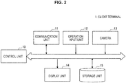
- FIG. 2 is a block diagram illustrating an example of the configuration of the client terminal 1 according to the present embodiment.
- the client terminal 1 may be a tablet terminal as illustrated in FIG. 1 , or may be a smartphone, a mobile phone terminal, a notebook-size personal computer, a desktop personal computer, a head mounted display (HMD), or the like. Further, as illustrated in FIG. 2 , the client terminal 1 includes a control unit 10, a communication unit 11, an operation input unit 12, a camera 13, a display unit 14 and a storage unit 15.
- the control unit 10 functions as an arithmetic processing unit and a control apparatus, and controls the whole operation within the client terminal 1 in accordance with various kinds of programs.
- the control unit 10 is realized with electronic circuits such as, for example, a central processing unit (CPU) and a microprocessor. Further, the control unit 10 may include a read only memory (ROM) which stores programs, operation parameters, or the like, to be used, and a random access memory (RAM) which temporarily stores parameters, or the like, which change as appropriate.
- ROM read only memory
- RAM random access memory
- the control unit 10 performs control to display various kinds of menu screens, a robot assembly screen, or the like, acquired from the server 2 at the display unit 14.
- the communication unit 11 is a communication module for transmitting and receiving data to and from other apparatuses in a wired / wireless manner.
- the communication unit 11 performs wireless communication with external devices directly or via a network access point using a scheme such as, for example, wired local area network (LAN), wireless LAN, Wi-Fi (registered trademark), infrared communication, Bluetooth (registered trademark) and near field communication / non-contact communication.
- LAN local area network
- Wi-Fi registered trademark
- infrared communication Bluetooth (registered trademark)
- near field communication / non-contact communication trademark
- the communication unit 11 is, for example, connected to the server 2 via the network 3 to transmit and receive data. Further, the communication unit 11 can be also connected to the robot 5 in a wired / wireless manner to transmit and receive data.
- the operation input unit 12 accepts an operation instruction from a user and outputs operation content thereof to the control unit 10.
- the operation input unit 12 may be a touch sensor, a pressure sensor or a proximity sensor which is provided integrally with the display unit 14.
- the operation input unit 12 may be a physical component such as a button, a switch and a lever, which is provided separately from the display unit 14.
- the camera 13 includes a lens system made up of an imaging lens, a diaphragm, a zoom lens, a focus lens, or the like, a drive system for causing the lens system to perform focus operation and zoom operation, a solid-state imaging element array which performs photoelectric conversion on an image pickup light obtained at the lens system to generate an image pickup signal, or the like.
- the solid-state imaging element array may be realized with, for example, a charge coupled device (CCD) sensor array or a complementary metal oxide semiconductor (CMOS) sensor array.
- CCD charge coupled device
- CMOS complementary metal oxide semiconductor
- the camera 13 acquires a captured image by capturing an image of the robot 5 created by the user.
- the display unit 14 is a display apparatus which outputs various kinds of display screens such as a menu screen and a robot assembly screen.
- This display unit 14 may be a display apparatus such as, for example, a liquid crystal display (LCD) and an organic electroluminescence (EL) display.
- LCD liquid crystal display
- EL organic electroluminescence
- the storage unit 15 stores programs and parameters to be used by the above-described control unit 10 to execute each function. Further, the storage unit 15 includes a storage apparatus including a storage medium, a recording apparatus which records data in the storage medium, a reading apparatus which reads out data from the storage medium, a deleting apparatus which deletes data recorded in the storage medium, or the like.
- this storage unit 15 may be, for example, a non-volatile memory such as a Flash ROM (or Flash Memory), an electrically erasable programmable read-only memory (EEPROM) and an erasable programmable ROM (EPROM), a magnetic disk such as a hard drive and a disk-shaped magnetic body disk, an optical disk such as a compact disc (CD), a digital versatile disc recordable (DVD-R) and a Blu-Ray Disc (registered trademark) (BD), and a storage medium such as a magneto optical (MO) disk.
- a non-volatile memory such as a Flash ROM (or Flash Memory), an electrically erasable programmable read-only memory (EEPROM) and an erasable programmable ROM (EPROM), a magnetic disk such as a hard drive and a disk-shaped magnetic body disk, an optical disk such as a compact disc (CD), a digital versatile disc recordable (DVD-R) and a Blu-Ray Disc (registered
- the configuration of the client terminal 1 according to the present embodiment has been described above. Note that the configuration of the client terminal 1 illustrated in FIG. 2 is an example, and the present embodiment is not limited to this.
- the client terminal 1 may further include a microphone and a speaker.
- FIG. 3 is a block diagram illustrating an example of the configuration of the server 2 according to the present embodiment.
- the server 2 includes a control unit 20, a communication unit 21 and a storage unit 22.
- the control unit 20 functions as an arithmetic processing unit and a control apparatus and controls the whole operation within the server 2 in accordance with various kinds of programs.
- the control unit 20 is realized with electronic circuits such as, for example, a CPU and a microprocessor. Further, the control unit 20 may include a ROM which stores programs, operation parameters, or the like, to be used and a RAM which temporarily stores parameters, or the like, which change as appropriate.
- the control unit 20 transmits display information of a menu screen to the client terminal 1 in response to a request from the client terminal 1 and performs each kind of predetermined processing in accordance with a menu selected by the user from the menu screen.
- the communication unit 21 is a communication module for transmitting and receiving data to and from other apparatuses in a wired / wireless manner.
- the communication unit 21 according to the present embodiment is connected to the client terminal 1 via the network 3 to transmit and receive data.
- the storage unit 22 stores programs and parameters to be used by the above-described control unit 10 to execute each function. Further, the storage unit 22 includes a storage apparatus including a storage medium, a recording apparatus which records data in the storage medium, a reading apparatus which reads out data from the storage medium, a deleting apparatus which deletes data recorded in the storage medium, or the like.
- the storage unit 22 stores user information and robot recipe data.
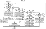
- FIG. 4 is a flowchart illustrating control processing at the client terminal 1 of the information processing system according to the present embodiment.
- the client terminal 1 displays a menu screen at the display unit 14 on the basis of the display information received from the server 2 (step S103).
- FIG. 5 illustrates an example of the menu screen.
- menu items such as robot recipe 301, learning course 302, free creation 303 and collection 304 are displayed as an example.
- robot recipe a number of robot recipes are presented so as to allow the user to freely select a recipe of a robot which the user desires to create.
- the "learning course” allows the user to learn assembly, programming, mechanisms of various kinds of electronic components, or the like, through creation of a robot.
- the "free creation” allows the user to freely create a program to be installed in the robot created by the user.
- the “collection” allows the user to register the robot and the program created by the user along with date, a title, a commemorative photo image, or the like. Operation processing in the case where each menu item is selected will be described below.
- FIG. 6 illustrates an example of the robot recipe search screen.
- a number of pieces of robot recipe data 311 and new creation display 312 when a new recipe is generated are displayed.
- the robot recipe data 311 can be narrowed down using a tagged keyword as a condition.
- the recipe data is searched by, for example, a magnifying glass icon illustrated in an upper right portion of the search screen 31 being tapped.
- FIG. 7 illustrates an example of a condition selection screen.
- the illustrated condition selection screen 32 is displayed when the magnifying glass icon illustrated in the upper right portion of the search screen 31 being tapped.
- a search result of recipes with which the selected keyword is tagged is displayed.
- a search result screen 33 as illustrated in FIG. 8 is displayed.
- robot recipe data in which "program is included” and concerning "car” is displayed.
- the new creation display 312 may be also displayed on the search result screen 33.
- FIG. 9 illustrates an example of a detailed information display screen of the robot recipe data.
- information such as an image of a completed robot, a title, a creator, a difficulty level and popularity is displayed.
- FIG. 9 in the case where information of parts possessed by the user is obtained, it is also possible to display whether or not the robot can be created with the parts possessed by the user, or, in the case where the parts are insufficient, which parts are lacking along with the information.
- the user taps a region where "create" is displayed and makes a final decision on selection of the robot recipe.
- the client terminal 1 starts assembly description of the selected robot recipe (step S115). Specifically, the client terminal 1 receives recipe data including robot assembly information, or the like, from the server 2 and displays an assembly description screen at the display unit 14. Specific examples of the assembly description screen will be described later with reference to FIG. 23 to FIG. 31 .
- the client terminal 1 starts creation of new robot recipe (step S118). Detailed content of the creation of new robot recipe will be described later.
- step S121 the client terminal 1 acquires learning course data from the server 2 (step S124) and displays a learning course selection screen (step S127).
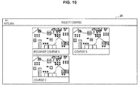
- FIG. 10 illustrates an example of the learning course selection screen.
- a plurality of learning courses such as, for example, "beginner course A", "course B” and "course C” is presented. The user selects an arbitrary course.
- FIG. 11 and FIG. 12 illustrate an example of the learning course screen.
- the learning course includes a plurality of stages, and display is controlled so that, for example, a town is gradually completed as a stage proceeds. If the user taps and selects an icon 361 of a stage, for example, a mission screen 38 as illustrated in FIG. 13 is displayed.
- a mission screen 38 a plurality of missions provided for learning content to be learned in the present stage in a stepwise manner is presented. If a mission is accomplished, a check mark is displayed, and an arrow mark is displayed at a mission to be learned next. Further, missions ahead are displayed in a grayed out state.
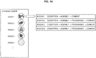
- one learning course includes a plurality of stages, and the user learns a mechanism of a robot, or the like, while creating a predetermined robot in each stage.
- one stage includes a plurality of missions.
- Each mission is provided to make the user understand learning content of the present stage in a stepwise manner. For example, in mission 1, description of motion of the robot, actual assembly of the robot and comment including review is provided. Further, in the next mission 2, description of motion of the robot, actual assembly of the robot, creation of a program which makes the robot operate and comment including review is provided.
- mission will be described with reference to FIG.
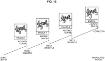
- the user learns elementary content by performing simple assembly, and, then, a difficulty level of learning is increased by making the user dismantle part of the assembled robot and perform a little more complicated assembly next. Further, a difficulty level of programming (coding) is increased in accordance with increase of the difficulty level of assembly. In this manner, in each mission, the user can grow up in a stepwise manner by difficulty levels of assembly of the robot and programming being gradually increased.
- each stage of the learning course and content and a difficulty level of missions in the stage may be flexibly changed in accordance with a learning level of the user.
- the client terminal 1 or the server 2 can judge the learning level of the user in accordance with a learning progress state of the user (such as learning time, quizzes as necessary, learning history and robot creation experience history) and change content or a difficulty level of the next mission or the next stage.
- the client terminal 1 provides a predetermined medal in accordance with robot creation and experience of the learning course by the user (step S133).
- a predetermined medal in accordance with robot creation and experience of the learning course by the user (step S133).
- proof of growth it is possible to provide various kinds of medals as proof of growth experience through creation of the robot recipe and each stage of the learning course, for example, when the user has learned a new program, when the user has noticed a mechanism of an object which the user did not know, when the user has experienced something for the first time, or when the user has achieved something.
- FIG. 16 illustrates an example of a medal collection screen.
- medals provided to the user are displayed.
- the respective medals are listed along with display of experience content.
- FIG. 17 is a diagram illustrating an example of types of medals to be provided in accordance with growth experience. As illustrated in FIG. 17 , for example, a medal in which a keyword indicating growth experience is described can be provided.
- FIG. 18 is a diagram illustrating an example of medal levels which change in accordance with a difficulty level of experience. As illustrated in FIG. 18 , medals of different colors such as bronze, silver, gold and platinum can be provided in accordance with the difficulty level of experience.
- the client terminal 1 may further generate and display skill collection from which content of skills which are newly acquired by the user can be confirmed again, and newspaper collection which indicates episode regarding the created robot in a newspaper form.
- step S136 the client terminal 1 displays a free creation screen at the display unit 14 on the basis of the screen display information acquired from the server 2 (step S139) and starts program creation processing (step S142).
- FIG. 19 illustrates an example of the free creation screen.
- display of "programming" for creating a program display of "commemorative photo” for registering a photo of the created robot, and an "add to collection” button for adding the created program and the photo of the robot as collection, are displayed.
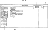
- FIG. 20 illustrates an example of the program creation screen.
- a display screen 411 for a module which visually indicates programming language, and a work region 412 for creating a program are displayed.
- the user can construct a program by dragging and moving a module from the display screen 411 to the work region 412. Further, the user can arbitrarily set a numerical value within the module. Then, if the user taps a program transfer button 413, the program constructed in the work region 412 is transmitted to the robot 5, and it is possible to make the robot 5 operate.
- the client terminal 1 accepts uploading of a captured image of the created robot and acquires the captured image (step S145).
- the captured image of the robot may be, for example, acquired by a camera of the client terminal 1.
- the client terminal 1 registers the created program and the uploaded captured image as collection of the user (step S148). Specifically, for example, the client terminal 1 transmits the created program and the captured image to the server 2 and performs control so that the created program and the captured image are stored as collection of the user.
- the client terminal 1 acquires collection data of the user from the server 2 (step S154) and displays a collection screen at the display unit 14 (step S157).
- FIG. 21 illustrates an example of the collection screen.
- the collection screen 42 includes display of the captured image and a title of the created robot, and display indicating through which of the learning course, free creation or the robot recipe, the robot is created.
- FIG. 22 is a diagram illustrating an example of a start screen of robot assembly description.
- the illustrated start screen 43 is displayed, for example, when a certain stage of the learning course is selected.
- description regarding content of the stage an image of the completed robot, and display of "create” are displayed. If the user taps the display of "create", description regarding actual assembly is started.
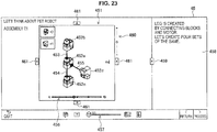
- FIG. 23 is a diagram illustrating an example of the assembly description screen.
- the illustrated assembly description screen 45 is a screen describing assembly of parts, and includes a drawing region 451 and a caption region 458. Display and non-display of the caption region 458 is controlled with a caption opening/closing button.
- the drawing region 451 It is possible to scale the drawing region 451 and move a viewpoint.
- the user can scale the viewpoint through, for example, pinch-in / pinch-out operation, manipulation of a scaling control bar 460 or mouse wheel manipulation, or can move the viewpoint centering around a base point through drag and drop or touch and swipe operation. Further, it is also possible to move the viewpoint upward, downward, rightward and leftward by direction buttons 461 provided above, below, on a right side and on a left side of the drawing region 451 being depressed and move the viewpoint upward, downward, rightward or leftward through drag and drop operation while a Shift key being depressed.
- the viewpoint may be automatically moved as part of assembly animation. For example, during jointing animation, the viewpoint may be moved to an angle at which a concavity and a convexity of joint portions of blocks can be seen.
- an animation progress bar 456 is displayed.
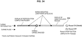
- the animation progress bar 456 indicates an animation time position within the step when assembly of parts is described using animation.
- details of the animation progress bar 456 will be described with reference to FIG. 24 .
- a handle of the animation progress bar 456 moves in accordance with reproduction of assembly animation to indicate the animation time position on a time axis bar.
- a "mark indicating a joint point of blocks" on the bar indicates an animation time position when the blocks are assembled, that is, when one block is jointed with another block. The handle can be dragged, so that the user can repeatedly reproduce joint portions of blocks, or the like, using a mark on the bar as an indication.
- space setting of the drawing region 451 may be displayed in a state where blocks 452a to 452d to be assembled are, for example, not grounded and float in the air. Further, in the case where a plurality of units of blocks to be assembled is required, the number may be clearly indicated by displaying " ⁇ number".
- joint surfaces of the blocks are highlighted and joint surfaces of the blocks are connected to each other with a line 453, a line 454 and a line 455.
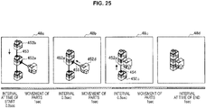
- Block jointing animation will be described next with reference to FIG. 25 .
- animation image 48a in FIG. 25 animation in which the block 452b moves along 453 which connects the joint surfaces of the block 452a and the block 452b, and is jointed with the block 452a, is reproduced.
- animation image 48b animation in which the block 452d moves along 453 which connects the joint surfaces of the block 452a and the block 452d, and is jointed with the block 452a, is reproduced.
- an animation image 48c animation in which the block 452c moves along 454 which connects joint surfaces of the block 452a and the block 452c, and is jointed with the block 452a, is reproduced. Then, an image 48d of a state where assembly of the blocks is finished is displayed.
- FIG. 26 illustrates block migration time and an indication of easing of one-time jointing.
- block migration speed upon jointing does not have to be constant speed, and migration speed may be slow upon start and upon end. It is possible to reproduce operation upon jointing which is particularly important in slow motion with animation having varying pace in this manner.
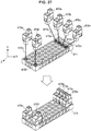
- FIG. 27 illustrates a diagram explaining another example of the jointing animation.
- the drawing region 451 may be divided into a plurality of portions.
- FIG. 28 illustrates an example where the drawing region is divided into a plurality of portions.
- the illustrated drawing region 465 is divided with, for example, a dividing line from an upper right side to a lower left side.
- a ratio of division can be changed in accordance with layout.
- a connecting portion can be enlarged and displayed using screen division layout.
- cable connection may be displayed at an angle at which silk of a cable can be seen.
- an icon 466 indicating that the viewpoint cannot be changed is displayed, and a move button and the scaling control bar are disabled.
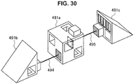
- FIG. 29 and FIG. 30 illustrate diagrams explaining other types of expression of a line connecting the joint surfaces. As illustrated in FIG.
- a line 492 which connects the joint surfaces is displayed in a similar manner to the above-described example.
- a line 493 which connects the joint surfaces is displayed so as to penetrate through the block 491a.
- FIG. 31 illustrates an example of animation across the steps.
- animation in which an angle of a block 501 assembled in the previous step is rotated is displayed in an assembly description screen 50a, as indicated in an assembly description screen 50b
- block jointing animation in the present step is displayed.
- migration time and easing in the rotation animation may be curved in a similar manner to that in the example illustrated in FIG. 26 .
- the assembly description screen according to the present embodiment has been specifically described above.
- the processing of creating the assembly description can be executed when, for example, the new creation display 312 for generating a new robot recipe illustrated in FIG. 6 is selected. Alternatively, the processing can be executed using application for creating an assembly description screen.
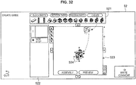
- FIG. 32 is a diagram illustrating an example of a creation screen for the assembly description.
- a block selection region 521 a block selection region 521, a step management region 522 and a work region 523 are displayed. If a block in the block selection region 521 is clicked, the selected block is lightly displayed in the work region 523, so that the user can confirm a shape of the block. Further, the user can move the selected block to the work region 523 by clicking and moving or dragging and dropping the selected block as illustrated in FIG. 32 .
- the selected block is displayed in a state where the block is adsorbed to the cursor.
- the block is displayed so as to be horizontal, vertical or parallel to other blocks as initial orientation of the block when the block enters the work region 523 (adsorbed at 90 degrees).
- an indicating line 524 is displayed by the cursor being hovered as illustrated in FIG. 32 .
- examples of a way of canceling the block adsorbed to the cursor include clicking a cursor icon on an upper left side of the work region 523, clicking the same block again, depressing an Esc key, or the like.
- FIG. 33 illustrates a diagram explaining block rotation operation.
- the cursor is separated from the block 525, only the block is displayed, and, if the cursor is hovered over the block 525, a selection frame 526 is displayed.
- selection frames 526a and 526b for the respective blocks are displayed in an overlapped manner.
- the indicating line 527 is extended from the center of the block 525.
- indicating lines are extended from the centers of the plurality of blocks.
- the user can rotate the block by 45 degrees each, for example, by hovering the cursor 528 over a black circle portion at a tip of the indicating line and clicking the black circle portion.
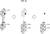
- FIG. 34 if a block 525a is made to approach a block 525b, if there are surfaces to which the block 525a can be jointed on one of the X, Y and Z axes, the corresponding portions are highlighted and connection lines are displayed. Then, in the case where the position is fixed in a state where the position deviates from the axis, the position is automatically corrected, and the block is adsorbed and jointed to the highlighted surfaces.
- a preview mode will be described next with reference to FIG. 37 .
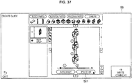
- the creation screen 56 enters a preview mode, a traveling control and a progress bar are displayed, the assembled blocks move to an animation start position, and temporary order of jointing animation based on the order in which the blocks are assembled is displayed. Further, the joint surfaces are highlighted, and lines connecting the joint surfaces are displayed.
- order in jointing (assembly) animation is first temporarily determined on the basis of assembly history through user operation upon an assembly mode. For example, in the case where a block 571b is jointed to a block 571a, and, then, a block 571c is jointed and, then, a block 571d is jointed, order of jointing is provided in this order.
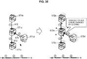
- selection frames 572 (572a to 572d) are displayed at all the blocks, and "assembly order can be changed by clicking" is displayed.
- FIG. 40 Another method for changing the assembly order in the preview mode will be described next with reference to FIG. 40 .
- the selection frame of the block 571a which becomes the assembly counterpart disappears, and first assembly is fixed.
- the block 571d is fixed as second assembly, because, in this example, the third assembly destination (that is, the block 571b) is naturally fixed, all the selection frames disappear.
- a method for changing an animation start point in the preview mode will be described next with reference to FIG. 41 .
- the preview mode it is possible to change the animation start point by dragging a block.
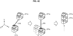
- animation becomes animation of two-staged movement in which a block 571c moves on the X axis and passes through a default start point, and as illustrated in a right portion of FIG. 42 , moves on the Y axis and is jointed to a block 571a.
- Migration time and easing of such two-staged movement may be set such that animation is made slow before and after the default start point in addition to a migration start point and an end point (upon jointing) as illustrated in, for example, FIG. 43 .
- a computer program for causing hardware such as a CPU, a ROM and a RAM incorporated in to the above-described client terminal 1 or server 2 to fulfill functions of the client terminal 1 or the server 2.
- a computer-readable storage medium which stores the computer program is also provided.
- present technology may also be configured as below.
Landscapes
- Engineering & Computer Science (AREA)
- Physics & Mathematics (AREA)
- Business, Economics & Management (AREA)
- Theoretical Computer Science (AREA)
- General Physics & Mathematics (AREA)
- Educational Technology (AREA)
- Entrepreneurship & Innovation (AREA)
- Educational Administration (AREA)
- Computer Hardware Design (AREA)
- Software Systems (AREA)
- General Engineering & Computer Science (AREA)
- Computer Graphics (AREA)
- Architecture (AREA)
- Processing Or Creating Images (AREA)
- Toys (AREA)
- User Interface Of Digital Computer (AREA)
- Manipulator (AREA)
Abstract
Description
- The present disclosure relates to an information processing apparatus, an information processing method, and a program.
- In related art, a toy for creating objects having various shapes by assembling a number of blocks is in widespread use. In recent years, electronic components such as a sensor, a motor, a control unit and a battery are also used in creation of a robot. The created robot is controlled by application installed in a control unit.
- Concerning a technology of adding application to an electronic device, for example, the following
Patent Literature 1 discloses a software installing method of additionally installing an additional function module to application which has been already installed in the electronic device. Further, as the electronic device disclosed inPatent Literature 1, an arbitrary device such as a host computer, a measurement device, an industrial robot, sewing machine and an image processing apparatus, which performs predetermined operation by a program being executed by a computer is assumed. - Patent Literature 1:
JP 2006-146835A - However, when a robot is created in accordance with description, there is a case where it is difficult only from the description and an image of an assembled completed robot to understand, for example, how concavities and convexities provided at respective blocks are fitted.
- Therefore, the present disclosure proposes an information processing apparatus, an information processing method, and a program which can improve user-friendliness of a description screen for assembly of parts in creation of a robot.
- According to the present disclosure, there is proposed an information processing apparatus including a control unit configured to perform display control to: separately display a plurality of parts for creation of a robot, display a line connecting joint surfaces of the respective parts, and display animation in which the respective parts are jointed in accordance with the line connecting the joint surfaces in assembly order.
- According to the present disclosure, there is proposed an information processing method including performing display control by a processor to: separately display a plurality of parts for creation of a robot, display a line connecting joint surfaces of the respective parts, and display animation for jointing the respective parts in accordance with the line connecting the joint surfaces in assembly order.
- According to the present disclosure, there is proposed a program for causing a computer to function as a display control unit configured to: separately display a plurality of parts for creation of a robot, display a line connecting joint surfaces of the respective parts, and display animation for jointing the respective parts in accordance with the line connecting the joint surfaces in assembly order.
- As described above, according to the present disclosure, it is possible to improve user-friendliness of a description screen for assembly of parts in creation of a robot.
- Note that the effects described above are not necessarily limitative. With or in the place of the above effects, there may be achieved any one of the effects described in this specification or other effects that may be grasped from this specification.
-
-
FIG. 1 is a diagram explaining outline of an information processing system according to an embodiment of the present disclosure. -
FIG. 2 is a block diagram illustrating an example of a configuration of a client terminal according to the embodiment. -
FIG. 3 is a block diagram illustrating an example of a configuration of a server according to the embodiment. -
FIG. 4 is a flowchart illustrating control processing at the client terminal of the information processing system according to the embodiment. -
FIG. 5 is a diagram illustrating an example of a menu screen according to the embodiment. -
FIG. 6 is a diagram illustrating an example of a robot recipe search screen according to the embodiment. -
FIG. 7 is a diagram illustrating an example of a condition selection screen according to the embodiment. -
FIG. 8 is a diagram illustrating an example of a search result screen according to the embodiment. -
FIG. 9 is a diagram illustrating an example of a detailed information display screen of robot recipe data according to the embodiment. -
FIG. 10 is a diagram illustrating an example of a learning course selection screen according to the embodiment. -
FIG. 11 is a diagram illustrating an example of a learning course screen according to the embodiment. -
FIG. 12 is a diagram illustrating an example of the learning course screen according to the embodiment. -
FIG. 13 is a diagram illustrating an example of a mission screen according to the embodiment. -
FIG. 14 is a diagram explaining each stage and missions of a learning course according to the embodiment. -
FIG. 15 is a diagram explaining each mission according to the embodiment. -
FIG. 16 is a diagram illustrating an example of a medal collection screen according to the embodiment. -
FIG. 17 is a diagram illustrating an example of a type of a medal provided in accordance with growth experience according to the embodiment. -
FIG. 18 is a diagram illustrating an example of a medal level which changes in accordance with a difficulty level of experience according to the embodiment. -
FIG. 19 is a diagram illustrating an example of a free creation screen according to the embodiment. -
FIG. 20 is a diagram illustrating an example of a program creation screen according to the embodiment. -
FIG. 21 is a diagram illustrating an example of a collection screen according to the embodiment. -
FIG. 22 is a diagram illustrating an example of a start screen of robot assembly description according to the embodiment. -
FIG. 23 is a diagram illustrating an example of an assembly description screen according to the embodiment. -
FIG. 24 is a diagram explaining details of an animation progress bar according to the embodiment. -
FIG. 25 is a diagram explaining block jointing animation according to the embodiment. -
FIG. 26 is a diagram illustrating block migration time and an indication of easing for one-time jointing according to the embodiment. -
FIG. 27 is a diagram explaining another example of the jointing animation according to the embodiment. -
FIG. 28 is a diagram illustrating an example where a drawing region is divided into a plurality of portions and displayed according to the embodiment. -
FIG. 29 is a diagram explaining another type of expression of a line connecting joint surfaces according to the embodiment. -
FIG. 30 is a diagram explaining another type of expression of the line connecting the joint surfaces according to the embodiment. -
FIG. 31 is a diagram illustrating an example of animation across steps according to the embodiment. -
FIG. 32 is a diagram illustrating an example of a creation screen for assembly description according to the embodiment. -
FIG. 33 is a diagram explaining block rotation operation according to the embodiment. -
FIG. 34 is a diagram explaining joint of blocks through adsorption according to the embodiment. -
FIG. 35 is a diagram explaining a case where a block in a previous step is utilized in a new step according to the embodiment. -
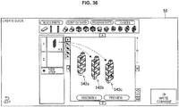
FIG. 36 is a diagram explaining a case where a plurality of blocks in a previous step is utilized according to the embodiment. -
FIG. 37 is a diagram explaining a preview mode according to the embodiment. -
FIG. 38 is a diagram explaining a method for changing assembly order in the preview mode according to the embodiment. -
FIG. 39 is a diagram explaining a method for changing the assembly order in the preview mode according to the embodiment. -
FIG. 40 is a diagram explaining another method for changing the assembly order in the preview mode according to the embodiment. -
FIG. 41 is a diagram explaining a method for changing an animation start point in the preview mode according to the embodiment. -
FIG. 42 is a diagram explaining two-staged movement by change of the animation start point according to the embodiment. -
FIG. 43 is a diagram explaining migration time in the two-staged movement according to the embodiment. - Hereinafter, (a) preferred embodiment(s) of the present disclosure will be described in detail with reference to the appended drawings. Note that, in this specification and the appended drawings, structural elements that have substantially the same function and structure are denoted with the same reference numerals, and repeated explanation of these structural elements is omitted.
- Further, description will be provided in the following order.
- 1. Outline of information processing system according to embodiment of present disclosure
- 2. Configuration
- 2-1. Configuration of client terminal
- 2-2. Configuration of server
- 3. Operation processing
- 4. Assembly description screen
- 5. Creation of assembly description
- 6. Conclusion
- Outline of an information processing system according to an embodiment of the present disclosure will be described with reference to
FIG. 1 . As illustrated inFIG. 1 , the information processing system according to the present embodiment includes aclient terminal 1 and aserver 2. Theclient terminal 1 and theserver 2 are connected to each other via anetwork 3 and transmit and receive data to and from each other. Further, theclient terminal 1 can install a program in arobot 5. Therobot 5 is created by a plurality of parts being assembled. - In the present embodiment, parts to be utilized for creation of a robot (constituting a robot) include electronic components such as a motor, a sensor and a cable in addiction to a block. The block is a color block made up of a number of types (for example, seven types) of polytopes or spheres having concavities and convexities to be fitted to other blocks. The block may have opaque color or may have permeability. A surface of the block can be subjected to various kinds of processing while touch by a user is taken into account. As the electronic components to be incorporated into the robot, in addition to the above-described motor, sensor and cable, a battery, a buzzer, a speaker, a display, a control unit, or the like, are assumed. As the sensor, for example, a touch sensor, a proximity sensor, an acceleration sensor, an angular velocity sensor, a geomagnetic sensor, an illuminance sensor, a temperature sensor, a pressure sensor, a biosensor (which can detect biological information of a user such as a pulse, perspiration, a brain wave, a sense of touch, a sense of smell and a sense of taste), a position detecting unit (such as a global navigation satellite system (GNSS) receiver), a camera, a microphone, or the like, are assumed.
- Here, as described above, when a robot is created in accordance with description, there is a case where it is difficult only from the description and an image of an assembled completed robot to understand, for example, how concavities and convexities provided at each block are fitted.
- Therefore, the present disclosure enables improvement of user-friendliness of a description screen for assembly of parts in creation of a robot using display indicating joint of parts and animation.
- Configurations of the
client terminal 1 and theserver 2 included in the information processing system according to an embodiment of the present disclosure will be specifically described below with reference to the drawings. -
FIG. 2 is a block diagram illustrating an example of the configuration of theclient terminal 1 according to the present embodiment. Theclient terminal 1 may be a tablet terminal as illustrated inFIG. 1 , or may be a smartphone, a mobile phone terminal, a notebook-size personal computer, a desktop personal computer, a head mounted display (HMD), or the like. Further, as illustrated inFIG. 2 , theclient terminal 1 includes acontrol unit 10, acommunication unit 11, anoperation input unit 12, acamera 13, adisplay unit 14 and astorage unit 15. - The
control unit 10 functions as an arithmetic processing unit and a control apparatus, and controls the whole operation within theclient terminal 1 in accordance with various kinds of programs. Thecontrol unit 10 is realized with electronic circuits such as, for example, a central processing unit (CPU) and a microprocessor. Further, thecontrol unit 10 may include a read only memory (ROM) which stores programs, operation parameters, or the like, to be used, and a random access memory (RAM) which temporarily stores parameters, or the like, which change as appropriate. - The
control unit 10 according to the present embodiment performs control to display various kinds of menu screens, a robot assembly screen, or the like, acquired from theserver 2 at thedisplay unit 14. - The
communication unit 11 is a communication module for transmitting and receiving data to and from other apparatuses in a wired / wireless manner. Thecommunication unit 11 performs wireless communication with external devices directly or via a network access point using a scheme such as, for example, wired local area network (LAN), wireless LAN, Wi-Fi (registered trademark), infrared communication, Bluetooth (registered trademark) and near field communication / non-contact communication. - The
communication unit 11 according to the present embodiment is, for example, connected to theserver 2 via thenetwork 3 to transmit and receive data. Further, thecommunication unit 11 can be also connected to therobot 5 in a wired / wireless manner to transmit and receive data. - The
operation input unit 12 accepts an operation instruction from a user and outputs operation content thereof to thecontrol unit 10. Theoperation input unit 12 may be a touch sensor, a pressure sensor or a proximity sensor which is provided integrally with thedisplay unit 14. Alternatively, theoperation input unit 12 may be a physical component such as a button, a switch and a lever, which is provided separately from thedisplay unit 14. - The
camera 13 includes a lens system made up of an imaging lens, a diaphragm, a zoom lens, a focus lens, or the like, a drive system for causing the lens system to perform focus operation and zoom operation, a solid-state imaging element array which performs photoelectric conversion on an image pickup light obtained at the lens system to generate an image pickup signal, or the like. The solid-state imaging element array may be realized with, for example, a charge coupled device (CCD) sensor array or a complementary metal oxide semiconductor (CMOS) sensor array. - The
camera 13 according to the present embodiment, for example, acquires a captured image by capturing an image of therobot 5 created by the user. - The
display unit 14 is a display apparatus which outputs various kinds of display screens such as a menu screen and a robot assembly screen. Thisdisplay unit 14 may be a display apparatus such as, for example, a liquid crystal display (LCD) and an organic electroluminescence (EL) display. - The
storage unit 15 stores programs and parameters to be used by the above-describedcontrol unit 10 to execute each function. Further, thestorage unit 15 includes a storage apparatus including a storage medium, a recording apparatus which records data in the storage medium, a reading apparatus which reads out data from the storage medium, a deleting apparatus which deletes data recorded in the storage medium, or the like. Note that thisstorage unit 15 may be, for example, a non-volatile memory such as a Flash ROM (or Flash Memory), an electrically erasable programmable read-only memory (EEPROM) and an erasable programmable ROM (EPROM), a magnetic disk such as a hard drive and a disk-shaped magnetic body disk, an optical disk such as a compact disc (CD), a digital versatile disc recordable (DVD-R) and a Blu-Ray Disc (registered trademark) (BD), and a storage medium such as a magneto optical (MO) disk. - The configuration of the
client terminal 1 according to the present embodiment has been described above. Note that the configuration of theclient terminal 1 illustrated inFIG. 2 is an example, and the present embodiment is not limited to this. For example, theclient terminal 1 may further include a microphone and a speaker. -
FIG. 3 is a block diagram illustrating an example of the configuration of theserver 2 according to the present embodiment. As illustrated inFIG. 3 , theserver 2 includes acontrol unit 20, acommunication unit 21 and astorage unit 22. - The
control unit 20 functions as an arithmetic processing unit and a control apparatus and controls the whole operation within theserver 2 in accordance with various kinds of programs. Thecontrol unit 20 is realized with electronic circuits such as, for example, a CPU and a microprocessor. Further, thecontrol unit 20 may include a ROM which stores programs, operation parameters, or the like, to be used and a RAM which temporarily stores parameters, or the like, which change as appropriate. - The
control unit 20 according to the present embodiment transmits display information of a menu screen to theclient terminal 1 in response to a request from theclient terminal 1 and performs each kind of predetermined processing in accordance with a menu selected by the user from the menu screen. - The
communication unit 21 is a communication module for transmitting and receiving data to and from other apparatuses in a wired / wireless manner. Thecommunication unit 21 according to the present embodiment is connected to theclient terminal 1 via thenetwork 3 to transmit and receive data. - The
storage unit 22 stores programs and parameters to be used by the above-describedcontrol unit 10 to execute each function. Further, thestorage unit 22 includes a storage apparatus including a storage medium, a recording apparatus which records data in the storage medium, a reading apparatus which reads out data from the storage medium, a deleting apparatus which deletes data recorded in the storage medium, or the like. - The
storage unit 22 according to the present embodiment, for example, stores user information and robot recipe data. - The configuration of the
server 2 according to the present embodiment has been described above. - Operation processing of the information processing system according to the present embodiment will be described next with reference to
FIG. 4. FIG. 4 is a flowchart illustrating control processing at theclient terminal 1 of the information processing system according to the present embodiment. - As illustrated in
FIG. 4 , first, theclient terminal 1 displays a menu screen at thedisplay unit 14 on the basis of the display information received from the server 2 (step S103). Here,FIG. 5 illustrates an example of the menu screen. In the illustratedmenu screen 30, menu items such asrobot recipe 301, learningcourse 302,free creation 303 andcollection 304 are displayed as an example. In the "robot recipe", a number of robot recipes are presented so as to allow the user to freely select a recipe of a robot which the user desires to create. The "learning course" allows the user to learn assembly, programming, mechanisms of various kinds of electronic components, or the like, through creation of a robot. The "free creation" allows the user to freely create a program to be installed in the robot created by the user. The "collection" allows the user to register the robot and the program created by the user along with date, a title, a commemorative photo image, or the like. Operation processing in the case where each menu item is selected will be described below. - Then, in the case where the "robot recipe" is selected (step S106: Yes), the
client terminal 1 acquires robot recipe data from the server 2 (step S109), and displays a robot recipe search screen (step S112). Here,FIG. 6 illustrates an example of the robot recipe search screen. In the illustratedsearch screen 31, a number of pieces ofrobot recipe data 311 andnew creation display 312 when a new recipe is generated, are displayed. Therobot recipe data 311 can be narrowed down using a tagged keyword as a condition. The recipe data is searched by, for example, a magnifying glass icon illustrated in an upper right portion of thesearch screen 31 being tapped. Here,FIG. 7 illustrates an example of a condition selection screen. The illustratedcondition selection screen 32 is displayed when the magnifying glass icon illustrated in the upper right portion of thesearch screen 31 being tapped. When the user selects a condition from a plurality of keywords displayed on thecondition selection screen 32 and taps "search", a search result of recipes with which the selected keyword is tagged is displayed. For example, in the case where "program is included" and "car" are selected as conditions, asearch result screen 33 as illustrated inFIG. 8 is displayed. In the illustratedsearch result screen 33, robot recipe data in which "program is included" and concerning "car" is displayed. Note that thenew creation display 312 may be also displayed on thesearch result screen 33. - The user taps the robot recipe data which the user desires to create and browses detailed information. Here,
FIG. 9 illustrates an example of a detailed information display screen of the robot recipe data. In the illustrated detailedinformation display screen 34, information such as an image of a completed robot, a title, a creator, a difficulty level and popularity is displayed. While not illustrated inFIG. 9 , in the case where information of parts possessed by the user is obtained, it is also possible to display whether or not the robot can be created with the parts possessed by the user, or, in the case where the parts are insufficient, which parts are lacking along with the information. In the case where the robot to be created is determined, the user taps a region where "create" is displayed and makes a final decision on selection of the robot recipe. - Then, the
client terminal 1 starts assembly description of the selected robot recipe (step S115). Specifically, theclient terminal 1 receives recipe data including robot assembly information, or the like, from theserver 2 and displays an assembly description screen at thedisplay unit 14. Specific examples of the assembly description screen will be described later with reference toFIG. 23 to FIG. 31 . - Further, in the case where new creation of robot recipe is selected, the
client terminal 1 starts creation of new robot recipe (step S118). Detailed content of the creation of new robot recipe will be described later. - Meanwhile, in the case where the "learning course" is selected (step S121: Yes), the
client terminal 1 acquires learning course data from the server 2 (step S124) and displays a learning course selection screen (step S127). Here,FIG. 10 illustrates an example of the learning course selection screen. In the illustrated learningcourse selection screen 35, a plurality of learning courses such as, for example, "beginner course A", "course B" and "course C" is presented. The user selects an arbitrary course. - Then, the
client terminal 1 starts processing of the learning course selected by the user (step S130). Here,FIG. 11 andFIG. 12 illustrate an example of the learning course screen. As illustrated inFIG. 11 andFIG. 12 , the learning course includes a plurality of stages, and display is controlled so that, for example, a town is gradually completed as a stage proceeds. If the user taps and selects anicon 361 of a stage, for example, amission screen 38 as illustrated inFIG. 13 is displayed. In themission screen 38, a plurality of missions provided for learning content to be learned in the present stage in a stepwise manner is presented. If a mission is accomplished, a check mark is displayed, and an arrow mark is displayed at a mission to be learned next. Further, missions ahead are displayed in a grayed out state. - Here, the learning course, each stage and missions according to the present embodiment will be described with reference to
FIG. 14 . As illustrated inFIG. 14 , for example, one learning course includes a plurality of stages, and the user learns a mechanism of a robot, or the like, while creating a predetermined robot in each stage. Further, as illustrated inFIG. 14 , one stage includes a plurality of missions. Each mission is provided to make the user understand learning content of the present stage in a stepwise manner. For example, inmission 1, description of motion of the robot, actual assembly of the robot and comment including review is provided. Further, in thenext mission 2, description of motion of the robot, actual assembly of the robot, creation of a program which makes the robot operate and comment including review is provided. Each mission will be described with reference toFIG. 15 . As illustrated inFIG. 15 , for example, inmission 1, the user learns elementary content by performing simple assembly, and, then, a difficulty level of learning is increased by making the user dismantle part of the assembled robot and perform a little more complicated assembly next. Further, a difficulty level of programming (coding) is increased in accordance with increase of the difficulty level of assembly. In this manner, in each mission, the user can grow up in a stepwise manner by difficulty levels of assembly of the robot and programming being gradually increased. - Note that each stage of the learning course and content and a difficulty level of missions in the stage may be flexibly changed in accordance with a learning level of the user. The client terminal 1 (or the server 2) can judge the learning level of the user in accordance with a learning progress state of the user (such as learning time, quizzes as necessary, learning history and robot creation experience history) and change content or a difficulty level of the next mission or the next stage.
- Then, the
client terminal 1 provides a predetermined medal in accordance with robot creation and experience of the learning course by the user (step S133). In the present embodiment, as proof of growth, it is possible to provide various kinds of medals as proof of growth experience through creation of the robot recipe and each stage of the learning course, for example, when the user has learned a new program, when the user has noticed a mechanism of an object which the user did not know, when the user has experienced something for the first time, or when the user has achieved something. - As a case where the user has learned a new program, for example, a case is assumed where the user has created a robot and learned using the following programs.
- Scratch language
- sequential processing
- repetition (loop circuit)
- pulse width modulation (PWN)
- acquisition of sensor values (an optical sensor, a touch sensor, a photoreflector, an acceleration sensor)
- conditional branch
- usage of a test mode
- control of a button
- utilization of a timer, timer control
- program of sound
- random number and random control
- write and a live mode
- motor control (a DC motor, a servo motor)
- execution of different kinds of control at the same time
- OR
- priority order
- utilization of an acceleration sensor (second time, how to use XYZ axes)
- variable
- Further, as a case where the user has newly noticed a mechanism of an object, for example, the following mechanisms and viewpoints are assumed.
- types of lighting (fire, candescence, fluorescence, LED)
- a Morse code
- spread of an LED
- understanding of an optical sensor
- an automatic lighting apparatus
- light control of RGB, produce color
- LED cases
- creation of melody
- a switch and a button
- vibration and sound, a speaker and ears
- create a virtual game
- bend and stretch
- a difference between a DC motor and a servo motor
- home electric appliances utilizing rotation
- a reciprocating slider-crank mechanism
- understanding of a photoreflector
- a mechanism of an automatic door
- care for safety
- an automatic door
- a mechanism of a toilet
- a difference between wheels and legs
- understanding of a servo motor
- Here,
FIG. 16 illustrates an example of a medal collection screen. In the illustratedmedal collection screen 39, medals provided to the user are displayed. The respective medals are listed along with display of experience content. - Further, an example of various kinds of medals to be provided to the user is illustrated in
FIG. 17 andFIG. 18 .FIG. 17 is a diagram illustrating an example of types of medals to be provided in accordance with growth experience. As illustrated inFIG. 17 , for example, a medal in which a keyword indicating growth experience is described can be provided.FIG. 18 is a diagram illustrating an example of medal levels which change in accordance with a difficulty level of experience. As illustrated inFIG. 18 , medals of different colors such as bronze, silver, gold and platinum can be provided in accordance with the difficulty level of experience. - Note that, while medals provided as proof of growth are described here, the
client terminal 1 may further generate and display skill collection from which content of skills which are newly acquired by the user can be confirmed again, and newspaper collection which indicates episode regarding the created robot in a newspaper form. - Then, in the case where the "free creation" is selected in the menu screen 30 (step S136: Yes), the
client terminal 1 displays a free creation screen at thedisplay unit 14 on the basis of the screen display information acquired from the server 2 (step S139) and starts program creation processing (step S142). Here,FIG. 19 illustrates an example of the free creation screen. In the illustratedfree creation screen 40, display of "programming" for creating a program, display of "commemorative photo" for registering a photo of the created robot, and an "add to collection" button for adding the created program and the photo of the robot as collection, are displayed. - If the display of "programming" is tapped, a program creation screen is displayed. Here,
FIG. 20 illustrates an example of the program creation screen. In the illustratedprogram creation screen 41, adisplay screen 411 for a module which visually indicates programming language, and awork region 412 for creating a program are displayed. The user can construct a program by dragging and moving a module from thedisplay screen 411 to thework region 412. Further, the user can arbitrarily set a numerical value within the module. Then, if the user taps aprogram transfer button 413, the program constructed in thework region 412 is transmitted to therobot 5, and it is possible to make therobot 5 operate. - Then, if the display of "commemorative photo" in the
free creation screen 40 inFIG. 19 is tapped, theclient terminal 1 accepts uploading of a captured image of the created robot and acquires the captured image (step S145). The captured image of the robot may be, for example, acquired by a camera of theclient terminal 1. - Then, if the "add to collection" button in the
free creation screen 40 inFIG. 19 is tapped, theclient terminal 1 registers the created program and the uploaded captured image as collection of the user (step S148). Specifically, for example, theclient terminal 1 transmits the created program and the captured image to theserver 2 and performs control so that the created program and the captured image are stored as collection of the user. - Subsequently, in the case where the "collection" is selected in the menu screen 30 (step S151: Yes), the
client terminal 1 acquires collection data of the user from the server 2 (step S154) and displays a collection screen at the display unit 14 (step S157). Here,FIG. 21 illustrates an example of the collection screen. In the illustratedcollection screen 42, a list of robots created by the user is displayed. Specifically, thecollection screen 42 includes display of the captured image and a title of the created robot, and display indicating through which of the learning course, free creation or the robot recipe, the robot is created. - The control processing of the
client terminal 1 according to the present embodiment has been specifically described above. Subsequently, an assembly description screen displayed at theclient terminal 1 when a robot is assembled through the above-described robot recipe or learning course will be specifically described usingFIG. 22 to FIG. 31 . -
FIG. 22 is a diagram illustrating an example of a start screen of robot assembly description. The illustratedstart screen 43 is displayed, for example, when a certain stage of the learning course is selected. In thestart screen 43, description regarding content of the stage, an image of the completed robot, and display of "create" are displayed. If the user taps the display of "create", description regarding actual assembly is started. -
FIG. 23 is a diagram illustrating an example of the assembly description screen. The illustratedassembly description screen 45 is a screen describing assembly of parts, and includes adrawing region 451 and acaption region 458. Display and non-display of thecaption region 458 is controlled with a caption opening/closing button. - It is possible to scale the
drawing region 451 and move a viewpoint. The user can scale the viewpoint through, for example, pinch-in / pinch-out operation, manipulation of ascaling control bar 460 or mouse wheel manipulation, or can move the viewpoint centering around a base point through drag and drop or touch and swipe operation. Further, it is also possible to move the viewpoint upward, downward, rightward and leftward bydirection buttons 461 provided above, below, on a right side and on a left side of thedrawing region 451 being depressed and move the viewpoint upward, downward, rightward or leftward through drag and drop operation while a Shift key being depressed. - Note that the viewpoint may be automatically moved as part of assembly animation. For example, during jointing animation, the viewpoint may be moved to an angle at which a concavity and a convexity of joint portions of blocks can be seen.
- Further, in the
drawing region 451, ananimation progress bar 456 is displayed. Theanimation progress bar 456 indicates an animation time position within the step when assembly of parts is described using animation. Here, details of theanimation progress bar 456 will be described with reference toFIG. 24 . As illustrated inFIG. 24 , a handle of theanimation progress bar 456 moves in accordance with reproduction of assembly animation to indicate the animation time position on a time axis bar. Further, a "mark indicating a joint point of blocks" on the bar indicates an animation time position when the blocks are assembled, that is, when one block is jointed with another block. The handle can be dragged, so that the user can repeatedly reproduce joint portions of blocks, or the like, using a mark on the bar as an indication. - Further, space setting of the
drawing region 451 may be displayed in a state whereblocks 452a to 452d to be assembled are, for example, not grounded and float in the air. Further, in the case where a plurality of units of blocks to be assembled is required, the number may be clearly indicated by displaying "× number". - Further, as illustrated in
FIG. 23 , joint surfaces of the blocks are highlighted and joint surfaces of the blocks are connected to each other with aline 453, aline 454 and aline 455. By this means, the user can intuitively recognize how to joint the blocks. - Block jointing animation will be described next with reference to
FIG. 25 . First, as illustrated in ananimation image 48a inFIG. 25 , animation in which theblock 452b moves along 453 which connects the joint surfaces of theblock 452a and theblock 452b, and is jointed with theblock 452a, is reproduced. Then, as illustrated in ananimation image 48b, animation in which theblock 452d moves along 453 which connects the joint surfaces of theblock 452a and theblock 452d, and is jointed with theblock 452a, is reproduced. Subsequently, as illustrated in ananimation image 48c, animation in which theblock 452c moves along 454 which connects joint surfaces of theblock 452a and theblock 452c, and is jointed with theblock 452a, is reproduced. Then, animage 48d of a state where assembly of the blocks is finished is displayed. By jointing of the blocks being indicated one by one with animation in the assembly description in this manner, the user can intuitively understand how to assemble the blocks. - In the example illustrated in
FIG. 25 , for example, upon start of animation, an interval of 0.5 sec is provided, in animation upon jointing, an interval of 1 sec is provided, and in animation between jointing and the next jointing, an interval of 0.5 sec is provided. Further, an interval of 1 sec is provided after the blocks are assembled. Here,FIG. 26 illustrates block migration time and an indication of easing of one-time jointing. As illustrated inFIG. 26 , for example, block migration speed upon jointing does not have to be constant speed, and migration speed may be slow upon start and upon end. It is possible to reproduce operation upon jointing which is particularly important in slow motion with animation having varying pace in this manner. - Note that, while, in the jointing animation, a block is basically made to move on coordinate on one of X, Y and Z, in the case where a plurality of blocks is displayed, exceptional display may be performed. Here,
FIG. 27 illustrates a diagram explaining another example of the jointing animation. - As illustrated in
FIG. 27 , for example, when a plurality of blocks 470 is jointed with ablock 471, animation in which ablock 470e and ablock 470f are jointed with theblock 471 only through movement on the Y axis respectively alonglines block 471 in a similar manner to that described in the above-described example, is reproduced. Meanwhile, because ablock 470a, ablock 470b, ablock 470c and ablock 470d overlap with each other,lines 472a to 472d which connect respective joint surfaces of the block 470 cannot be vertically expressed, and are displayed while an angle is formed as illustrated inFIG. 27 , and animation in which the blocks sequentially and obliquely move along thelines 472a to 472d and are jointed, is reproduced. - Further, the
drawing region 451 may be divided into a plurality of portions. Here,FIG. 28 illustrates an example where the drawing region is divided into a plurality of portions. The illustrateddrawing region 465 is divided with, for example, a dividing line from an upper right side to a lower left side. A ratio of division can be changed in accordance with layout. Further, as illustrated inFIG. 28 , a connecting portion can be enlarged and displayed using screen division layout. Further, when cable connection is described, cable connection may be displayed at an angle at which silk of a cable can be seen. Still further, it is also possible to highlight a word (for example "K2") described at a connection destination of the cable. Further, in the case where a viewpoint cannot be changed because 2D objects are superimposed, anicon 466 indicating that the viewpoint cannot be changed is displayed, and a move button and the scaling control bar are disabled. - Further, display of a line connecting the joint surfaces of the blocks is not limited to the above-described examples. For example, in the case where the blocks are displayed at an angle at which the joint surfaces cannot be seen, because there is a case where it is difficult to understand to which surface the block should be jointed, the blocks may be displayed while hidden joint surfaces are taken into account. Here,
FIG. 29 andFIG. 30 illustrate diagrams explaining other types of expression of a line connecting the joint surfaces. As illustrated inFIG. 29 , for example, in a case of animation in which ablock 491b and ablock 491c are jointed to ablock 491a, because a joint surface of theblock 491a to which theblock 491b is to be jointed can be seen, aline 492 which connects the joint surfaces is displayed in a similar manner to the above-described example. Meanwhile, because a joint surface of theblock 491a to which theblock 491c is to be jointed cannot be seen, aline 493 which connects the joint surfaces is displayed so as to penetrate through theblock 491a. Further, as illustrated inFIG. 30 , by indicating the joint surface of theblock 491a to which theblock 491c is to be jointed with a hidden line and extending a line 495 (a hidden line at a portion which is hidden by theblock 491a) to the joint surface, it is possible to realize display which can be easily understood. - Further, in the case where blocks which are being assembled are displayed at a different angle in the next assembly step, it is also possible to switch display with smooth animation from display at an angle in the previous step. Here,
FIG. 31 illustrates an example of animation across the steps. In the illustrated example, after animation in which an angle of ablock 501 assembled in the previous step is rotated is displayed in anassembly description screen 50a, as indicated in anassembly description screen 50b, block jointing animation in the present step is displayed. Note that migration time and easing in the rotation animation may be curved in a similar manner to that in the example illustrated inFIG. 26 . By this means, because animation in which the assembled blocks are rotated is displayed following the previous step before the blocks are suddenly displayed at a different angle across the steps, the user can intuitively understand that orientation of the assembled blocks is changed. - The assembly description screen according to the present embodiment has been specifically described above.
- Subsequently, processing when the above-described assembly description is created will be described with reference to
FIG. 32 to FIG. 43 . The processing of creating the assembly description can be executed when, for example, thenew creation display 312 for generating a new robot recipe illustrated inFIG. 6 is selected. Alternatively, the processing can be executed using application for creating an assembly description screen. -
FIG. 32 is a diagram illustrating an example of a creation screen for the assembly description. In the illustratedcreation screen 52, ablock selection region 521, astep management region 522 and awork region 523 are displayed. If a block in theblock selection region 521 is clicked, the selected block is lightly displayed in thework region 523, so that the user can confirm a shape of the block. Further, the user can move the selected block to thework region 523 by clicking and moving or dragging and dropping the selected block as illustrated inFIG. 32 . - If a cursor enters the
work region 523, the selected block is displayed in a state where the block is adsorbed to the cursor. The block is displayed so as to be horizontal, vertical or parallel to other blocks as initial orientation of the block when the block enters the work region 523 (adsorbed at 90 degrees). If the position is fixed by clicking, after the position is fixed, an indicatingline 524 is displayed by the cursor being hovered as illustrated inFIG. 32 . Note that examples of a way of canceling the block adsorbed to the cursor include clicking a cursor icon on an upper left side of thework region 523, clicking the same block again, depressing an Esc key, or the like. - After the block is disposed within the
work region 523, it is possible to rotate the block by operating the indicating line. Here,FIG. 33 illustrates a diagram explaining block rotation operation. In the illustrated example, if the cursor is separated from theblock 525, only the block is displayed, and, if the cursor is hovered over theblock 525, aselection frame 526 is displayed. In the case where the cursor is hovered over a plurality of jointed blocks (blocks - Then, the indicating
line 527 is extended from the center of theblock 525. Upon selection of a plurality of blocks, indicating lines are extended from the centers of the plurality of blocks. The user can rotate the block by 45 degrees each, for example, by hovering thecursor 528 over a black circle portion at a tip of the indicating line and clicking the black circle portion. Further, it is also possible to freely move the block body by dragging and dropping the block or move the block while the X, Y and Z axes are fixed by dragging and dropping the indicating line. - Subsequently, joint of blocks through adsorption will be described with reference to
FIG. 34 . As illustrated inFIG. 34 , if ablock 525a is made to approach ablock 525b, if there are surfaces to which theblock 525a can be jointed on one of the X, Y and Z axes, the corresponding portions are highlighted and connection lines are displayed. Then, in the case where the position is fixed in a state where the position deviates from the axis, the position is automatically corrected, and the block is adsorbed and jointed to the highlighted surfaces. - A case where the block in the previous step is utilized in a new step will be described next with reference to
FIG. 35 . If "new step" displayed on thecreation screen 54 inFIG. 32 is tapped, as indicated in thecreation screen 54 inFIG. 35 , asecond step 541 is added. Here, theblock 542 which is created in a first step can be brought in a work region in thesecond step 541 by theblock 542 being dragged and dropped. - Note that, as illustrated in
FIG. 36 , in the case where a plurality of blocks (542a to 542c) in the previous step is brought, display of "× number" is added in an assembly step (the previous step) of the blocks. - A preview mode will be described next with reference to
FIG. 37 . As illustrated inFIG. 37 , if apreview button 561 is tapped, thecreation screen 56 enters a preview mode, a traveling control and a progress bar are displayed, the assembled blocks move to an animation start position, and temporary order of jointing animation based on the order in which the blocks are assembled is displayed. Further, the joint surfaces are highlighted, and lines connecting the joint surfaces are displayed. - A method for changing assembly order in the preview mode will be described next with reference to
FIG. 38 andFIG. 39 . As illustrated in a left portion ofFIG. 38 , order in jointing (assembly) animation is first temporarily determined on the basis of assembly history through user operation upon an assembly mode. For example, in the case where ablock 571b is jointed to ablock 571a, and, then, ablock 571c is jointed and, then, ablock 571d is jointed, order of jointing is provided in this order. - In the case where such temporary order is changed, as illustrated in a right portion of
FIG. 38 , if the cursor is hovered over the block, selection frames 572 (572a to 572d) are displayed at all the blocks, and "assembly order can be changed by clicking" is displayed. - Then, as illustrated in a left portion of
FIG. 39 , for example, if theblock 571a is clicked, the selection frame of the block disappears, and "select a block to be assembled next" is displayed. As illustrated inFIG. 39 , in the case where there is a plurality of assembly destinations, order is not fixed until the counterpart is selected. Then, if the user clicks, for example, theblock 571d as illustrated in a right portion ofFIG. 39 , first assembly is fixed. Note that, if a portion other than blocks is selected during setting of order, selection of order is cancelled, and the order returns to default order. - Another method for changing the assembly order in the preview mode will be described next with reference to
FIG. 40 . As illustrated in a left portion ofFIG. 40 , in the case where there is one assembly destination of theblock 571c which is clicked first, as illustrated in a central portion ofFIG. 40 , the selection frame of theblock 571a which becomes the assembly counterpart disappears, and first assembly is fixed. Then, as illustrated in a right portion ofFIG. 40 , if theblock 571d is fixed as second assembly, because, in this example, the third assembly destination (that is, theblock 571b) is naturally fixed, all the selection frames disappear. - A method for changing an animation start point in the preview mode will be described next with reference to
FIG. 41 . In the preview mode, it is possible to change the animation start point by dragging a block. - For example, as illustrated in a left portion of
FIG. 41 , in a case of movement only on the same axis (in an example illustrated inFIG. 41 , on the Y axis), only a movement distance of animation is changed, and migration time is not changed. - Meanwhile, in a case of movement on two or more axes (in an example illustrated in
FIG. 41 , on the Y axis and the X axis) as illustrated in a right portion ofFIG. 41 , the movement becomes two-staged movement via a default animation start point. Such two-staged movement will be described with reference toFIG. 42 . - As illustrated in a left portion and a central portion of
FIG. 42 , for example, animation becomes animation of two-staged movement in which ablock 571c moves on the X axis and passes through a default start point, and as illustrated in a right portion ofFIG. 42 , moves on the Y axis and is jointed to ablock 571a. Migration time and easing of such two-staged movement may be set such that animation is made slow before and after the default start point in addition to a migration start point and an end point (upon jointing) as illustrated in, for example,FIG. 43 . - As described above, in the information processing system according to the embodiment of the present disclosure, it is possible to improve user-friendliness of a description screen for assembly of parts in creation of a robot.
- The preferred embodiment(s) of the present disclosure has/have been described above with reference to the accompanying drawings, whilst the present disclosure is not limited to the above examples. A person skilled in the art may find various alterations and modifications within the scope of the appended claims, and it should be understood that they will naturally come under the technical scope of the present disclosure.
- For example, it is also possible to create a computer program for causing hardware such as a CPU, a ROM and a RAM incorporated in to the above-described
client terminal 1 orserver 2 to fulfill functions of theclient terminal 1 or theserver 2. Further, a computer-readable storage medium which stores the computer program is also provided. - Further, the effects described in this specification are merely illustrative or exemplified effects, and are not limitative. That is, with or in the place of the above effects, the technology according to the present disclosure may achieve other effects that are clear to those skilled in the art from the description of this specification.
- Additionally, the present technology may also be configured as below.
- (1) An information processing apparatus including a display control unit configured to:
- separately display a plurality of parts for creation of a robot,
- display a line connecting joint surfaces of the respective parts, and
- display animation in which the respective parts are jointed in accordance with the line connecting the joint surfaces in assembly order.
- (2) The information processing apparatus according to (1),
in which the control unit performs control such that the joint surfaces are highlighted. - (3) The information processing apparatus according to (1) or (2),
in which the control unit performs control to additionally display a progress bar which displays an animation time position in an assembly step. - (4) The information processing apparatus according to (3),
in which a mark indicating a joint time position in the assembly step is displayed in the progress bar. - (5) The information processing apparatus according to any one of (1) to (4),
in which the control unit performs control such that speed of animation in which the parts are jointed is made slow at times of start and end of movement. - (6) The information processing apparatus according to any one of (1) to (5),
in which the control unit generates assembly description information for creation of a robot in accordance with a learning course. - (7) The information processing apparatus according to (6),
in which the learning course includes a plurality of stages, and the stage includes a plurality of missions. - (8) The information processing apparatus according to (7),
in which the learning course, the stages and the missions change in accordance with a learning level of a user. - (9) An information processing method including performing display control by a processor to:
- separately display a plurality of parts for creation of a robot,
- display a line connecting joint surfaces of the respective parts, and
- display animation for jointing the respective parts in accordance with the line connecting the joint surfaces in assembly order.
- (10) A program for causing a computer to function as a display control unit configured to:
- separately display a plurality of parts for creation of a robot,
- display a line connecting joint surfaces of the respective parts, and
- display animation for jointing the respective parts in accordance with the line connecting the joint surfaces in assembly order.
-
- 1
- client terminal
- 2
- server
- 3
- network
- 5
- robot
- 10
- control unit
- 11
- communication unit
- 12
- operation input unit
- 13
- camera
- 14
- display unit
- 15
- storage unit
- 20
- control unit
- 21
- communication unit
- 22
- storage unit
- 30
- menu screen
- 31
- search screen
- 32
- condition selection screen
- 33
- search result screen
- 34
- detailed information display screen
- 35
- learning course selection screen
- 38
- mission screen
- 39
- medal collection screen
- 40
- free creation screen
- 41
- program creation screen
- 42
- collection screen
- 43
- start screen
- 45
- assembly description screen
- 48a to 48c
- animation image
- 48d
- image
- 50a, 50b
- assembly description screen
- 52
- creation screen
- 54
- creation screen
- 56
- creation screen
- 301
- robot recipe
- 302
- learning course
- 303
- free creation
- 304
- collection
- 311
- robot recipe data
- 312
- new creation display
- 411
- display screen
- 412
- work region
- 413
- program transfer button
- 451
- drawing region
- 452a to 452d
- block
- 453 to 455
- line
- 456
- animation progress bar
- 458
- caption region
- 460
- scaling control bar
- 461
- direction button
- 465
- drawing region
Claims (10)
- An information processing apparatus comprising a control unit configured to perform display control to:separately display a plurality of parts for creation of a robot,display a line connecting joint surfaces of the respective parts, anddisplay animation in which the respective parts are jointed in accordance with the line connecting the joint surfaces in assembly order.
- The information processing apparatus according to claim 1,
wherein the control unit performs control such that the joint surfaces are highlighted. - The information processing apparatus according to claim 1,
wherein the control unit performs control to additionally display a progress bar which displays an animation time position in an assembly step. - The information processing apparatus according to claim 3,
wherein a mark indicating a joint time position in the assembly step is displayed in the progress bar. - The information processing apparatus according to claim 1,
wherein the control unit performs control such that speed of animation in which the parts are jointed is made slow at times of start and end of movement. - The information processing apparatus according to claim 1,
wherein the control unit generates assembly description information for creation of a robot in accordance with a learning course. - The information processing apparatus according to claim 6,
wherein the learning course includes a plurality of stages, and the stage includes a plurality of missions. - The information processing apparatus according to claim 7,
wherein the learning course, the stages and the missions change in accordance with a learning level of a user. - An information processing method comprising performing display control by a processor to:separately display a plurality of parts for creation of a robot,display a line connecting joint surfaces of the respective parts, anddisplay animation for jointing the respective parts in accordance with the line connecting the joint surfaces in assembly order.
- A program for causing a computer to function as a display control unit configured to:separately display a plurality of parts for creation of a robot,display a line connecting joint surfaces of the respective parts, anddisplay animation for jointing the respective parts in accordance with the line connecting the joint surfaces in assembly order.
Applications Claiming Priority (2)
| Application Number | Priority Date | Filing Date | Title |
|---|---|---|---|
| JP2016168986 | 2016-08-31 | ||
| PCT/JP2017/019982 WO2018042784A1 (en) | 2016-08-31 | 2017-05-30 | Information processing device, information processing method, and program |
Publications (3)
| Publication Number | Publication Date |
|---|---|
| EP3509053A1 true EP3509053A1 (en) | 2019-07-10 |
| EP3509053A4 EP3509053A4 (en) | 2019-07-31 |
| EP3509053B1 EP3509053B1 (en) | 2020-08-26 |
Family
ID=61301833
Family Applications (1)
| Application Number | Title | Priority Date | Filing Date |
|---|---|---|---|
| EP17845795.8A Not-in-force EP3509053B1 (en) | 2016-08-31 | 2017-05-30 | Information processing device, information processing method, and program |
Country Status (5)
| Country | Link |
|---|---|
| US (1) | US11430195B2 (en) |
| EP (1) | EP3509053B1 (en) |
| JP (2) | JP7036016B2 (en) |
| CN (1) | CN109643500B (en) |
| WO (1) | WO2018042784A1 (en) |
Cited By (1)
| Publication number | Priority date | Publication date | Assignee | Title |
|---|---|---|---|---|
| CN111524420A (en) * | 2020-04-24 | 2020-08-11 | 上海鲸鱼机器人科技有限公司 | Robot programming system and method and robot |
Families Citing this family (5)
| Publication number | Priority date | Publication date | Assignee | Title |
|---|---|---|---|---|
| CN109726481B (en) * | 2018-12-29 | 2023-08-04 | 深圳市优必选科技有限公司 | Auxiliary method and device for robot construction and terminal equipment |
| JP6539000B1 (en) * | 2019-02-13 | 2019-07-03 | 株式会社白紙とロック | Numerical calculation system of plural individuals, numerical calculation method, program |
| KR102146375B1 (en) * | 2019-04-03 | 2020-08-20 | 전남과학대학교 산학협력단 | Platform system for robot simulator based on mixed reality |
| CN110322775B (en) * | 2019-05-30 | 2021-06-29 | 广东省机场管理集团有限公司工程建设指挥部 | Airport information display method and device, computer equipment and storage medium |
| USD1087981S1 (en) | 2022-10-31 | 2025-08-12 | Resmed Corp. | Display screen with graphical user interface |
Family Cites Families (32)
| Publication number | Priority date | Publication date | Assignee | Title |
|---|---|---|---|---|
| JP3602037B2 (en) * | 1999-08-23 | 2004-12-15 | 株式会社フジエ | How to create a moving image data file |
| JP2002056406A (en) * | 2000-08-08 | 2002-02-22 | Clim Ncd:Kk | Assembly process support system and recording medium recorded with its data |
| US6873344B2 (en) | 2001-02-22 | 2005-03-29 | Sony Corporation | Media production system using flowgraph representation of operations |
| JP2003051031A (en) | 2001-05-08 | 2003-02-21 | Komatsu Ltd | System and method for displaying an electronic document about a product or a part thereof on a client terminal |
| JP2003223094A (en) * | 2002-01-30 | 2003-08-08 | Mitsubishi Heavy Ind Ltd | Electronic assembly procedure manual system, system and method for supporting creation of assembly procedure manual |
| US7413040B2 (en) * | 2003-08-12 | 2008-08-19 | White Box Robotics, Inc. | Robot with removable mounting elements |
| US20050231512A1 (en) * | 2004-04-16 | 2005-10-20 | Niles Gregory E | Animation of an object using behaviors |
| US20070262984A1 (en) * | 2004-06-17 | 2007-11-15 | Lego A/S | Automatic Generation of Building Instructions for Building Block Models |
| JP2006146835A (en) | 2004-11-25 | 2006-06-08 | Juki Corp | Software installation method and software installation program |
| JP2007299370A (en) * | 2006-04-06 | 2007-11-15 | Ricoh Co Ltd | Information processing apparatus, information processing method, and information processing program |
| US7979251B2 (en) * | 2007-03-16 | 2011-07-12 | Lego A/S | Automatic generation of building instructions for building element models |
| CN101216862B (en) * | 2008-01-16 | 2011-06-15 | 南京航空航天大学 | Paper-free three-dimensional assemblage process document accomplishing method |
| TWI393309B (en) * | 2010-01-20 | 2013-04-11 | Powertech Ind Ltd | Reversable and concealable electrical power receptacle |
| US20110179624A1 (en) * | 2010-01-26 | 2011-07-28 | Z-Line Designs, Inc. | Animated assembly system |
| JP2011211481A (en) * | 2010-03-30 | 2011-10-20 | Hitachi Consumer Electronics Co Ltd | Video/audio player |
| KR101186105B1 (en) * | 2011-06-09 | 2012-10-09 | 이학용 | Educational material |
| JP5595492B2 (en) * | 2012-02-06 | 2014-09-24 | 株式会社アーテック | Connectable block |
| JP6044553B2 (en) * | 2012-02-10 | 2016-12-14 | ソニー株式会社 | Information processing apparatus, information processing method, and program |
| US9403100B2 (en) * | 2012-02-17 | 2016-08-02 | Technologyone, Inc. | Baseplate assembly for use with toy pieces |
| CN102629388B (en) * | 2012-04-28 | 2014-01-01 | 上海隧道工程股份有限公司 | Mechanical equipment simulation system generating method |
| US9094692B2 (en) * | 2012-10-05 | 2015-07-28 | Ebay Inc. | Systems and methods for marking content |
| CN202958068U (en) * | 2012-10-26 | 2013-05-29 | 光宝电子(广州)有限公司 | Slide cover device |
| US20140298223A1 (en) * | 2013-02-06 | 2014-10-02 | Peter Duong | Systems and methods for drawing shapes and issuing gesture-based control commands on the same draw grid |
| US20140272905A1 (en) * | 2013-03-15 | 2014-09-18 | Adapt Courseware | Adaptive learning systems and associated processes |
| JP2014238476A (en) * | 2013-06-07 | 2014-12-18 | 有限会社エレガンテ | Cosmetic technician education system |
| EP2852143A1 (en) * | 2013-09-18 | 2015-03-25 | Nokia Corporation | Creating a cinemagraph |
| CN104735552A (en) * | 2013-12-23 | 2015-06-24 | 北京中传数广技术有限公司 | Live video label inserting method and system |
| JP6177146B2 (en) * | 2014-01-21 | 2017-08-09 | 株式会社ソニー・インタラクティブエンタテインメント | Information processing apparatus and information processing method |
| JP6475435B2 (en) * | 2014-07-30 | 2019-02-27 | 川崎重工業株式会社 | Robot control program generation method and apparatus |
| CN204229690U (en) * | 2014-08-20 | 2015-03-25 | 李丙林 | A kind ofly to tear open with manual animation, the lettering machine of mosaic body structure |
| US20160104311A1 (en) * | 2014-10-14 | 2016-04-14 | Microsoft Technology Licensing, Llc. | Animation framework |
| CN105243681A (en) * | 2015-09-23 | 2016-01-13 | 国网上海市电力公司 | Construction method and device for three-dimensional dynamic model of power device |
-
2017
- 2017-05-30 US US16/320,808 patent/US11430195B2/en active Active
- 2017-05-30 JP JP2018536943A patent/JP7036016B2/en active Active
- 2017-05-30 WO PCT/JP2017/019982 patent/WO2018042784A1/en not_active Ceased
- 2017-05-30 CN CN201780051282.XA patent/CN109643500B/en active Active
- 2017-05-30 EP EP17845795.8A patent/EP3509053B1/en not_active Not-in-force
-
2022
- 2022-02-24 JP JP2022026778A patent/JP7294474B2/en active Active
Cited By (1)
| Publication number | Priority date | Publication date | Assignee | Title |
|---|---|---|---|---|
| CN111524420A (en) * | 2020-04-24 | 2020-08-11 | 上海鲸鱼机器人科技有限公司 | Robot programming system and method and robot |
Also Published As
| Publication number | Publication date |
|---|---|
| JP2022081525A (en) | 2022-05-31 |
| JP7294474B2 (en) | 2023-06-20 |
| JP7036016B2 (en) | 2022-03-15 |
| US11430195B2 (en) | 2022-08-30 |
| JPWO2018042784A1 (en) | 2019-06-24 |
| CN109643500B (en) | 2022-04-19 |
| EP3509053A4 (en) | 2019-07-31 |
| CN109643500A (en) | 2019-04-16 |
| EP3509053B1 (en) | 2020-08-26 |
| WO2018042784A1 (en) | 2018-03-08 |
| US20190172269A1 (en) | 2019-06-06 |
Similar Documents
| Publication | Publication Date | Title |
|---|---|---|
| EP3509053B1 (en) | Information processing device, information processing method, and program | |
| US9626103B2 (en) | Systems and methods for identifying media portions of interest | |
| US11347378B2 (en) | Display apparatus, user terminal, control method, and computer-readable medium | |
| US12026362B2 (en) | Video editing application for mobile devices | |
| TWI442382B (en) | Image processing device, image processing method and program | |
| JP5398970B2 (en) | Mobile communication device and control method | |
| WO2023134491A1 (en) | Page display control method and apparatus, and mobile terminal and storage medium | |
| JP6933213B2 (en) | Information processing equipment, information processing methods, and programs | |
| US20260050374A1 (en) | Gesture-based virtual interfaces | |
| CN117492555A (en) | Object movement control method, device and equipment | |
| JP5765444B2 (en) | Information processing apparatus, image processing method, program, and information processing system | |
| JP2019023902A (en) | Program and information processing device | |
| HK40097707A (en) | Scrolling and navigation in virtual reality | |
| Van Tonder | Enhanced Sensor-based Interaction Techniques for Mobile Map-based Applications | |
| O'Dwyer | What's that building? The use of App Inventor to create an interactive mobile application campus tour |
Legal Events
| Date | Code | Title | Description |
|---|---|---|---|
| STAA | Information on the status of an ep patent application or granted ep patent |
Free format text: STATUS: THE INTERNATIONAL PUBLICATION HAS BEEN MADE |
|
| PUAI | Public reference made under article 153(3) epc to a published international application that has entered the european phase |
Free format text: ORIGINAL CODE: 0009012 |
|
| STAA | Information on the status of an ep patent application or granted ep patent |
Free format text: STATUS: REQUEST FOR EXAMINATION WAS MADE |
|
| 17P | Request for examination filed |
Effective date: 20190321 |
|
| AK | Designated contracting states |
Kind code of ref document: A1 Designated state(s): AL AT BE BG CH CY CZ DE DK EE ES FI FR GB GR HR HU IE IS IT LI LT LU LV MC MK MT NL NO PL PT RO RS SE SI SK SM TR |
|
| AX | Request for extension of the european patent |
Extension state: BA ME |
|
| A4 | Supplementary search report drawn up and despatched |
Effective date: 20190628 |
|
| RIC1 | Information provided on ipc code assigned before grant |
Ipc: A63H 33/08 20060101ALI20190624BHEP Ipc: G09B 19/10 20060101AFI20190624BHEP Ipc: A63H 33/04 20060101ALI20190624BHEP Ipc: G06T 13/20 20110101ALI20190624BHEP |
|
| DAV | Request for validation of the european patent (deleted) | ||
| DAX | Request for extension of the european patent (deleted) | ||
| GRAP | Despatch of communication of intention to grant a patent |
Free format text: ORIGINAL CODE: EPIDOSNIGR1 |
|
| STAA | Information on the status of an ep patent application or granted ep patent |
Free format text: STATUS: GRANT OF PATENT IS INTENDED |
|
| INTG | Intention to grant announced |
Effective date: 20200318 |
|
| GRAS | Grant fee paid |
Free format text: ORIGINAL CODE: EPIDOSNIGR3 |
|
| GRAA | (expected) grant |
Free format text: ORIGINAL CODE: 0009210 |
|
| STAA | Information on the status of an ep patent application or granted ep patent |
Free format text: STATUS: THE PATENT HAS BEEN GRANTED |
|
| AK | Designated contracting states |
Kind code of ref document: B1 Designated state(s): AL AT BE BG CH CY CZ DE DK EE ES FI FR GB GR HR HU IE IS IT LI LT LU LV MC MK MT NL NO PL PT RO RS SE SI SK SM TR |
|
| REG | Reference to a national code |
Ref country code: GB Ref legal event code: FG4D |
|
| REG | Reference to a national code |
Ref country code: CH Ref legal event code: EP |
|
| REG | Reference to a national code |
Ref country code: AT Ref legal event code: REF Ref document number: 1307112 Country of ref document: AT Kind code of ref document: T Effective date: 20200915 |
|
| REG | Reference to a national code |
Ref country code: IE Ref legal event code: FG4D |
|
| REG | Reference to a national code |
Ref country code: DE Ref legal event code: R096 Ref document number: 602017022547 Country of ref document: DE |
|
| REG | Reference to a national code |
Ref country code: NL Ref legal event code: FP |
|
| REG | Reference to a national code |
Ref country code: LT Ref legal event code: MG4D |
|
| PG25 | Lapsed in a contracting state [announced via postgrant information from national office to epo] |
Ref country code: NO Free format text: LAPSE BECAUSE OF FAILURE TO SUBMIT A TRANSLATION OF THE DESCRIPTION OR TO PAY THE FEE WITHIN THE PRESCRIBED TIME-LIMIT Effective date: 20201126 Ref country code: GR Free format text: LAPSE BECAUSE OF FAILURE TO SUBMIT A TRANSLATION OF THE DESCRIPTION OR TO PAY THE FEE WITHIN THE PRESCRIBED TIME-LIMIT Effective date: 20201127 Ref country code: FI Free format text: LAPSE BECAUSE OF FAILURE TO SUBMIT A TRANSLATION OF THE DESCRIPTION OR TO PAY THE FEE WITHIN THE PRESCRIBED TIME-LIMIT Effective date: 20200826 Ref country code: LT Free format text: LAPSE BECAUSE OF FAILURE TO SUBMIT A TRANSLATION OF THE DESCRIPTION OR TO PAY THE FEE WITHIN THE PRESCRIBED TIME-LIMIT Effective date: 20200826 Ref country code: SE Free format text: LAPSE BECAUSE OF FAILURE TO SUBMIT A TRANSLATION OF THE DESCRIPTION OR TO PAY THE FEE WITHIN THE PRESCRIBED TIME-LIMIT Effective date: 20200826 Ref country code: BG Free format text: LAPSE BECAUSE OF FAILURE TO SUBMIT A TRANSLATION OF THE DESCRIPTION OR TO PAY THE FEE WITHIN THE PRESCRIBED TIME-LIMIT Effective date: 20201126 Ref country code: PT Free format text: LAPSE BECAUSE OF FAILURE TO SUBMIT A TRANSLATION OF THE DESCRIPTION OR TO PAY THE FEE WITHIN THE PRESCRIBED TIME-LIMIT Effective date: 20201228 Ref country code: HR Free format text: LAPSE BECAUSE OF FAILURE TO SUBMIT A TRANSLATION OF THE DESCRIPTION OR TO PAY THE FEE WITHIN THE PRESCRIBED TIME-LIMIT Effective date: 20200826 |
|
| REG | Reference to a national code |
Ref country code: AT Ref legal event code: MK05 Ref document number: 1307112 Country of ref document: AT Kind code of ref document: T Effective date: 20200826 |
|
| PG25 | Lapsed in a contracting state [announced via postgrant information from national office to epo] |
Ref country code: LV Free format text: LAPSE BECAUSE OF FAILURE TO SUBMIT A TRANSLATION OF THE DESCRIPTION OR TO PAY THE FEE WITHIN THE PRESCRIBED TIME-LIMIT Effective date: 20200826 Ref country code: PL Free format text: LAPSE BECAUSE OF FAILURE TO SUBMIT A TRANSLATION OF THE DESCRIPTION OR TO PAY THE FEE WITHIN THE PRESCRIBED TIME-LIMIT Effective date: 20200826 Ref country code: RS Free format text: LAPSE BECAUSE OF FAILURE TO SUBMIT A TRANSLATION OF THE DESCRIPTION OR TO PAY THE FEE WITHIN THE PRESCRIBED TIME-LIMIT Effective date: 20200826 Ref country code: IS Free format text: LAPSE BECAUSE OF FAILURE TO SUBMIT A TRANSLATION OF THE DESCRIPTION OR TO PAY THE FEE WITHIN THE PRESCRIBED TIME-LIMIT Effective date: 20201226 |
|
| PG25 | Lapsed in a contracting state [announced via postgrant information from national office to epo] |
Ref country code: SM Free format text: LAPSE BECAUSE OF FAILURE TO SUBMIT A TRANSLATION OF THE DESCRIPTION OR TO PAY THE FEE WITHIN THE PRESCRIBED TIME-LIMIT Effective date: 20200826 Ref country code: EE Free format text: LAPSE BECAUSE OF FAILURE TO SUBMIT A TRANSLATION OF THE DESCRIPTION OR TO PAY THE FEE WITHIN THE PRESCRIBED TIME-LIMIT Effective date: 20200826 Ref country code: RO Free format text: LAPSE BECAUSE OF FAILURE TO SUBMIT A TRANSLATION OF THE DESCRIPTION OR TO PAY THE FEE WITHIN THE PRESCRIBED TIME-LIMIT Effective date: 20200826 Ref country code: DK Free format text: LAPSE BECAUSE OF FAILURE TO SUBMIT A TRANSLATION OF THE DESCRIPTION OR TO PAY THE FEE WITHIN THE PRESCRIBED TIME-LIMIT Effective date: 20200826 Ref country code: CZ Free format text: LAPSE BECAUSE OF FAILURE TO SUBMIT A TRANSLATION OF THE DESCRIPTION OR TO PAY THE FEE WITHIN THE PRESCRIBED TIME-LIMIT Effective date: 20200826 |
|
| REG | Reference to a national code |
Ref country code: DE Ref legal event code: R097 Ref document number: 602017022547 Country of ref document: DE |
|
| PG25 | Lapsed in a contracting state [announced via postgrant information from national office to epo] |
Ref country code: ES Free format text: LAPSE BECAUSE OF FAILURE TO SUBMIT A TRANSLATION OF THE DESCRIPTION OR TO PAY THE FEE WITHIN THE PRESCRIBED TIME-LIMIT Effective date: 20200826 Ref country code: AT Free format text: LAPSE BECAUSE OF FAILURE TO SUBMIT A TRANSLATION OF THE DESCRIPTION OR TO PAY THE FEE WITHIN THE PRESCRIBED TIME-LIMIT Effective date: 20200826 Ref country code: AL Free format text: LAPSE BECAUSE OF FAILURE TO SUBMIT A TRANSLATION OF THE DESCRIPTION OR TO PAY THE FEE WITHIN THE PRESCRIBED TIME-LIMIT Effective date: 20200826 |
|
| PG25 | Lapsed in a contracting state [announced via postgrant information from national office to epo] |
Ref country code: SK Free format text: LAPSE BECAUSE OF FAILURE TO SUBMIT A TRANSLATION OF THE DESCRIPTION OR TO PAY THE FEE WITHIN THE PRESCRIBED TIME-LIMIT Effective date: 20200826 |
|
| PLBE | No opposition filed within time limit |
Free format text: ORIGINAL CODE: 0009261 |
|
| STAA | Information on the status of an ep patent application or granted ep patent |
Free format text: STATUS: NO OPPOSITION FILED WITHIN TIME LIMIT |
|
| RAP4 | Party data changed (patent owner data changed or rights of a patent transferred) |
Owner name: SONY GROUP CORPORATION |
|
| PG25 | Lapsed in a contracting state [announced via postgrant information from national office to epo] |
Ref country code: IT Free format text: LAPSE BECAUSE OF FAILURE TO SUBMIT A TRANSLATION OF THE DESCRIPTION OR TO PAY THE FEE WITHIN THE PRESCRIBED TIME-LIMIT Effective date: 20200826 |
|
| 26N | No opposition filed |
Effective date: 20210527 |
|
| PG25 | Lapsed in a contracting state [announced via postgrant information from national office to epo] |
Ref country code: SI Free format text: LAPSE BECAUSE OF FAILURE TO SUBMIT A TRANSLATION OF THE DESCRIPTION OR TO PAY THE FEE WITHIN THE PRESCRIBED TIME-LIMIT Effective date: 20200826 |
|
| REG | Reference to a national code |
Ref country code: CH Ref legal event code: PL |
|
| GBPC | Gb: european patent ceased through non-payment of renewal fee |
Effective date: 20210530 |
|
| PG25 | Lapsed in a contracting state [announced via postgrant information from national office to epo] |
Ref country code: CH Free format text: LAPSE BECAUSE OF NON-PAYMENT OF DUE FEES Effective date: 20210531 Ref country code: LU Free format text: LAPSE BECAUSE OF NON-PAYMENT OF DUE FEES Effective date: 20210530 Ref country code: MC Free format text: LAPSE BECAUSE OF FAILURE TO SUBMIT A TRANSLATION OF THE DESCRIPTION OR TO PAY THE FEE WITHIN THE PRESCRIBED TIME-LIMIT Effective date: 20200826 Ref country code: LI Free format text: LAPSE BECAUSE OF NON-PAYMENT OF DUE FEES Effective date: 20210531 |
|
| REG | Reference to a national code |
Ref country code: BE Ref legal event code: MM Effective date: 20210531 |
|
| PG25 | Lapsed in a contracting state [announced via postgrant information from national office to epo] |
Ref country code: IE Free format text: LAPSE BECAUSE OF NON-PAYMENT OF DUE FEES Effective date: 20210530 Ref country code: GB Free format text: LAPSE BECAUSE OF NON-PAYMENT OF DUE FEES Effective date: 20210530 |
|
| PG25 | Lapsed in a contracting state [announced via postgrant information from national office to epo] |
Ref country code: FR Free format text: LAPSE BECAUSE OF NON-PAYMENT OF DUE FEES Effective date: 20210531 |
|
| PG25 | Lapsed in a contracting state [announced via postgrant information from national office to epo] |
Ref country code: BE Free format text: LAPSE BECAUSE OF NON-PAYMENT OF DUE FEES Effective date: 20210531 |
|
| PG25 | Lapsed in a contracting state [announced via postgrant information from national office to epo] |
Ref country code: CY Free format text: LAPSE BECAUSE OF FAILURE TO SUBMIT A TRANSLATION OF THE DESCRIPTION OR TO PAY THE FEE WITHIN THE PRESCRIBED TIME-LIMIT Effective date: 20200826 |
|
| P01 | Opt-out of the competence of the unified patent court (upc) registered |
Effective date: 20230528 |
|
| PG25 | Lapsed in a contracting state [announced via postgrant information from national office to epo] |
Ref country code: HU Free format text: LAPSE BECAUSE OF FAILURE TO SUBMIT A TRANSLATION OF THE DESCRIPTION OR TO PAY THE FEE WITHIN THE PRESCRIBED TIME-LIMIT; INVALID AB INITIO Effective date: 20170530 |
|
| PG25 | Lapsed in a contracting state [announced via postgrant information from national office to epo] |
Ref country code: MK Free format text: LAPSE BECAUSE OF FAILURE TO SUBMIT A TRANSLATION OF THE DESCRIPTION OR TO PAY THE FEE WITHIN THE PRESCRIBED TIME-LIMIT Effective date: 20200826 |
|
| PGFP | Annual fee paid to national office [announced via postgrant information from national office to epo] |
Ref country code: NL Payment date: 20240418 Year of fee payment: 8 |
|
| PGFP | Annual fee paid to national office [announced via postgrant information from national office to epo] |
Ref country code: DE Payment date: 20240418 Year of fee payment: 8 |
|
| PG25 | Lapsed in a contracting state [announced via postgrant information from national office to epo] |
Ref country code: MT Free format text: LAPSE BECAUSE OF FAILURE TO SUBMIT A TRANSLATION OF THE DESCRIPTION OR TO PAY THE FEE WITHIN THE PRESCRIBED TIME-LIMIT Effective date: 20200826 |
|
| REG | Reference to a national code |
Ref country code: DE Ref legal event code: R119 Ref document number: 602017022547 Country of ref document: DE |
|
| PG25 | Lapsed in a contracting state [announced via postgrant information from national office to epo] |
Ref country code: TR Free format text: LAPSE BECAUSE OF FAILURE TO SUBMIT A TRANSLATION OF THE DESCRIPTION OR TO PAY THE FEE WITHIN THE PRESCRIBED TIME-LIMIT Effective date: 20200826 |
|
| REG | Reference to a national code |
Ref country code: NL Ref legal event code: MM Effective date: 20250601 |
|
| PG25 | Lapsed in a contracting state [announced via postgrant information from national office to epo] |
Ref country code: NL Free format text: LAPSE BECAUSE OF NON-PAYMENT OF DUE FEES Effective date: 20250601 |
|
| PG25 | Lapsed in a contracting state [announced via postgrant information from national office to epo] |
Ref country code: DE Free format text: LAPSE BECAUSE OF NON-PAYMENT OF DUE FEES Effective date: 20251202 |