EP3509051A1 - Vehicle travel control method and vehicle travel control device - Google Patents
Vehicle travel control method and vehicle travel control device Download PDFInfo
- Publication number
- EP3509051A1 EP3509051A1 EP16915226.1A EP16915226A EP3509051A1 EP 3509051 A1 EP3509051 A1 EP 3509051A1 EP 16915226 A EP16915226 A EP 16915226A EP 3509051 A1 EP3509051 A1 EP 3509051A1
- Authority
- EP
- European Patent Office
- Prior art keywords
- area
- vehicle
- host vehicle
- travelable
- travel control
- Prior art date
- Legal status (The legal status is an assumption and is not a legal conclusion. Google has not performed a legal analysis and makes no representation as to the accuracy of the status listed.)
- Ceased
Links
Images





Classifications
-
- G—PHYSICS
- G08—SIGNALLING
- G08G—TRAFFIC CONTROL SYSTEMS
- G08G1/00—Traffic control systems for road vehicles
- G08G1/16—Anti-collision systems
- G08G1/167—Driving aids for lane monitoring, lane changing, e.g. blind spot detection
-
- G—PHYSICS
- G08—SIGNALLING
- G08G—TRAFFIC CONTROL SYSTEMS
- G08G1/00—Traffic control systems for road vehicles
- G08G1/16—Anti-collision systems
- G08G1/166—Anti-collision systems for active traffic, e.g. moving vehicles, pedestrians, bikes
-
- B—PERFORMING OPERATIONS; TRANSPORTING
- B60—VEHICLES IN GENERAL
- B60W—CONJOINT CONTROL OF VEHICLE SUB-UNITS OF DIFFERENT TYPE OR DIFFERENT FUNCTION; CONTROL SYSTEMS SPECIALLY ADAPTED FOR HYBRID VEHICLES; ROAD VEHICLE DRIVE CONTROL SYSTEMS FOR PURPOSES NOT RELATED TO THE CONTROL OF A PARTICULAR SUB-UNIT
- B60W30/00—Purposes of road vehicle drive control systems not related to the control of a particular sub-unit, e.g. of systems using conjoint control of vehicle sub-units
- B60W30/10—Path keeping
-
- B—PERFORMING OPERATIONS; TRANSPORTING
- B60—VEHICLES IN GENERAL
- B60W—CONJOINT CONTROL OF VEHICLE SUB-UNITS OF DIFFERENT TYPE OR DIFFERENT FUNCTION; CONTROL SYSTEMS SPECIALLY ADAPTED FOR HYBRID VEHICLES; ROAD VEHICLE DRIVE CONTROL SYSTEMS FOR PURPOSES NOT RELATED TO THE CONTROL OF A PARTICULAR SUB-UNIT
- B60W30/00—Purposes of road vehicle drive control systems not related to the control of a particular sub-unit, e.g. of systems using conjoint control of vehicle sub-units
- B60W30/14—Adaptive cruise control
- B60W30/16—Control of distance between vehicles, e.g. keeping a distance to preceding vehicle
- B60W30/165—Automatically following the path of a preceding lead vehicle, e.g. "electronic tow-bar"
-
- B—PERFORMING OPERATIONS; TRANSPORTING
- B60—VEHICLES IN GENERAL
- B60W—CONJOINT CONTROL OF VEHICLE SUB-UNITS OF DIFFERENT TYPE OR DIFFERENT FUNCTION; CONTROL SYSTEMS SPECIALLY ADAPTED FOR HYBRID VEHICLES; ROAD VEHICLE DRIVE CONTROL SYSTEMS FOR PURPOSES NOT RELATED TO THE CONTROL OF A PARTICULAR SUB-UNIT
- B60W40/00—Estimation or calculation of non-directly measurable driving parameters for road vehicle drive control systems not related to the control of a particular sub unit, e.g. by using mathematical models
- B60W40/02—Estimation or calculation of non-directly measurable driving parameters for road vehicle drive control systems not related to the control of a particular sub unit, e.g. by using mathematical models related to ambient conditions
- B60W40/06—Road conditions
-
- B—PERFORMING OPERATIONS; TRANSPORTING
- B60—VEHICLES IN GENERAL
- B60W—CONJOINT CONTROL OF VEHICLE SUB-UNITS OF DIFFERENT TYPE OR DIFFERENT FUNCTION; CONTROL SYSTEMS SPECIALLY ADAPTED FOR HYBRID VEHICLES; ROAD VEHICLE DRIVE CONTROL SYSTEMS FOR PURPOSES NOT RELATED TO THE CONTROL OF A PARTICULAR SUB-UNIT
- B60W40/00—Estimation or calculation of non-directly measurable driving parameters for road vehicle drive control systems not related to the control of a particular sub unit, e.g. by using mathematical models
- B60W40/02—Estimation or calculation of non-directly measurable driving parameters for road vehicle drive control systems not related to the control of a particular sub unit, e.g. by using mathematical models related to ambient conditions
- B60W40/06—Road conditions
- B60W40/072—Curvature of the road
-
- G—PHYSICS
- G08—SIGNALLING
- G08G—TRAFFIC CONTROL SYSTEMS
- G08G1/00—Traffic control systems for road vehicles
- G08G1/16—Anti-collision systems
-
- B—PERFORMING OPERATIONS; TRANSPORTING
- B60—VEHICLES IN GENERAL
- B60W—CONJOINT CONTROL OF VEHICLE SUB-UNITS OF DIFFERENT TYPE OR DIFFERENT FUNCTION; CONTROL SYSTEMS SPECIALLY ADAPTED FOR HYBRID VEHICLES; ROAD VEHICLE DRIVE CONTROL SYSTEMS FOR PURPOSES NOT RELATED TO THE CONTROL OF A PARTICULAR SUB-UNIT
- B60W2552/00—Input parameters relating to infrastructure
-
- B—PERFORMING OPERATIONS; TRANSPORTING
- B60—VEHICLES IN GENERAL
- B60Y—INDEXING SCHEME RELATING TO ASPECTS CROSS-CUTTING VEHICLE TECHNOLOGY
- B60Y2300/00—Purposes or special features of road vehicle drive control systems
- B60Y2300/10—Path keeping
Definitions
- the present disclosure relates to a vehicle travel control method and a vehicle travel control device for controlling a host vehicle so as to follow a preceding vehicle.
- Patent Document 1 Japanese Laid-Open Patent Application No. 2007-176290
- the gain that is used for feedback control for following the preceding vehicle is temporarily reduced in order to suppress the vehicle behavior from changing significantly.
- an object of the present disclosure is to realize a vehicle travel control with which it is possible to suppress the vehicle behavior from changing significantly and to ensure the ability to follow the preceding vehicle, when the preceding vehicle changes over.
- the following process is executed upon detecting a new preceding vehicle cutting in between the preceding vehicle and the host vehicle. That is, a first area where the host vehicle can possible travel is calculated from a travel trajectory of the new preceding vehicle; a travelable area of the host vehicle up to a previous time is set as a second area; and the first area and the second area are added to define the travelable area. Moreover, a target travel trajectory of the host vehicle is generated in the defined travelable area, and the host vehicle is controlled along the generated target travel trajectory.
- FIG 1 is a block diagram schematically illustrating a vehicle travel control system 1 according to the first embodiment.
- the vehicle travel control system 1 shown in Figure 1 comprises an object detection sensor 21, a wheel speed sensor 22, a yaw rate sensor 23, an object recognition calculator 24, a vehicle control calculator 30, and an actuator 40.
- the vehicle travel control system 1 is a system that is mounted on a host vehicle 10.
- the object detection sensor 21 detects the presence/absence of an obstacle or a preceding vehicle that is present in the vicinity of the host vehicle 10.
- the object detection sensor 21 is composed of a scanning laser radar, a millimeter wave radar, or the like.
- the wheel speed sensor 22 is provided on the left and right driven wheels of the host vehicle 10 and detects the rotational speed of the driven wheels. The rotational speed detected by the wheel speed sensor 22 is used for calculating the vehicle speed and the direction of travel of the host vehicle 10.
- the yaw rate sensor 23 detects rotational angular velocity of the host vehicle 10. The rotational angular velocity detected by the yaw rate sensor 23 is used for calculating the bearing of the host vehicle 10.
- the object recognition calculator 24 detects the position of an object detected by the object detection sensor 21 and determines whether the detected object is a preceding vehicle based on the size of the object, the relative speed with respect to the host vehicle 10, and the like. During detection of a preceding vehicle, the object recognition calculator also labels the preceding vehicle. Thus, it is possible detect a changeover of the preceding vehicle when a different vehicle cuts in between the preceding vehicle and the host vehicle 10, or when the preceding vehicle changes lanes. The object recognition calculator 24 calculates the vehicle speed of the detected preceding vehicle, as well as an inter-vehicular distance between the preceding vehicle and the host vehicle 10 in order to realize the preceding vehicle following control.
- the vehicle control calculator 30 comprises a travelable area calculation unit 301, a memory 302, a trajectory generation unit 303, and a travel control unit 304.
- the travelable area calculation unit 301 calculates an area where the host vehicle 10 can possibly travel based on the calculation result of the object recognition calculator 24 and the detection results of the wheel speed sensor 22 and the yaw rate sensor 23.
- the travelable area calculated by the travelable area calculation unit 301 is stored in the memory 302 and transmitted to the trajectory generation unit 303.
- the trajectory generation unit 303 generates a target travel trajectory T of the host vehicle 10 within the received travelable area.
- the target travel trajectory T generated by the trajectory generation unit 303 is transmitted to the travel control unit 304.
- the travel control unit 304 calculate the respective control amount for steering, accelerator, brake, etc. (none shown), such that the host vehicle 10 can travel along the received target travel trajectory T.
- the travel control unit drives the actuator 40 based on the calculated control amounts.
- the actuator 40 is composed of a steering actuator, a drive actuator, a braking actuator, and the like.
- Figure 2 is a flow chart illustrating a vehicle travel control process of the first embodiment that is executed by the vehicle control calculator 30 (more precisely, by a processor incorporated in the vehicle control calculator 30).
- the flow chart illustrated in Figure 2 is executed when a start condition for the preceding vehicle following control is satisfied. Whether the start condition for the preceding vehicle following control has been satisfied is determined when the preceding vehicle is present and, for example, based on an ON/OFF state of an execution switch for the preceding vehicle following control that is provided in the driver's seat of the host vehicle 10, or on a traffic condition.
- Step S31 the preceding vehicle is detected by means of the object detection sensor 21 and the object recognition calculator 24.
- the travelable area calculation unit 301 calculates the travelable area present between the host vehicle 10 and the preceding vehicle detected in Step S31 as a first area A. Specifically, the travel trajectory on which the preceding vehicle actually travels between the current position of the host vehicle and the current position of the preceding vehicle is calculated as the first area A. This is because the area based on the trajectory on which the preceding vehicle has already traveled also can be determined as travelable for the host vehicle 10.
- the first area may be the travel trajectory itself (that is, corresponding only to the width of the preceding vehicle), an area in which the travel trajectory is expanded to the width of the travel lane, or be set to an intermediate width therebetween.
- Step S33 the travelable area calculation unit 301 sets the travelable area calculated up to a previous time as a second area B. That is, the entire area that is determined to be travelable in a process loop immediately before the current process loop is read from the memory 302 and is set as the second area B described above.
- the first and second areas, etc. are calculated based on relative coordinates with the host vehicle 10 as the origin.
- Step S33 when the travelable area of the host vehicle 10 up to the previous time is set as the second area B, a coordinate transform that corresponds to the movement amount and movement direction of the host vehicle 10 between the previous time and the current time is carried out.
- the coordinate transform described above can be carried out by calculating the movement amount and the movement direction of the host vehicle 10 by means of dead reckoning from the outputs of the wheel speed sensor 22 and the yaw rate sensor 23.
- the coordinate transform may be carried out by calculating the movement amount and the movement direction of the host vehicle 10 by means of odometry from the output of the wheel speed sensor 22.
- Step S34 the first area A calculated in Step S32 and the second area B calculated in Step S33 are added to calculate the travelable area C. That is, the travelable area C indicates the entire area that can be determined as currently travelable.
- the calculation result of Step S34 is stored in the memory 302 and used when the second area B is set in the subsequent process loop.
- Step S35 the trajectory generation unit 303 generates the target travel trajectory T of the host vehicle 10 in a central region within the travelable area C calculated in Step S34.
- the central region refers to a region obtained by expanding a center line of the travelable area C by a prescribed amount (for example, by half the vehicle width of the host vehicle 10).
- Step S36 a follow control that controls the travel of the host vehicle 10 along the target travel trajectory T generated in Step S35 is carried out.
- the travel control unit 304 calculates the control amounts, such as the steering, in accordance with the target travel trajectory T and drives the actuator 40 based on the calculated control amounts to thereby achieve the follow control.
- Step S37 it is determined whether the follow control should be stopped. If the result is negative, the process returns to Step S31 and repeats the process described above. If the result is affirmative, the present vehicle travel control process is ended. Whether the follow control should be stopped is determined based on whether the start condition for the preceding vehicle following control is satisfied.
- Step S31 If a changeover of the preceding vehicle occurs during execution of the flow chart of Figure 2 , it is detected that a changeover of the preceding vehicle occurred by the object recognition calculator 24 in Step S31, and, in the subsequent Step S32, the first area A is calculated based on the new preceding vehicle.
- Steps S32 to S34 The processing of the travelable area calculation unit 301 described above (Steps S32 to S34) will be described with reference to Figures 3 and 4 .
- Figure 3 illustrates the situation around the time that a cut-in of a preceding vehicle occurs, arranged in chronological order.
- the travelable area calculation unit 301 calculates the first area A based on the travel trajectory of the current preceding vehicle 100. If there is a travelable area that was calculated in the previous process loop, said travelable area is set as the second area B, and the first area A and the second area B are added to calculate the current travelable area C. Since the situation shown on the left side of Figure 3 indicates the first process of executing the flow chart of Figure 2 , the second area B is not present. Therefore, the first area A becomes the current travelable area C.
- the travelable area calculation unit 301 calculates a new first area A based on the travel trajectory of the new preceding vehicle 110.
- the travelable area calculation unit 301 sets the area that was the travelable area of the host vehicle 10 up to the previous time, calculated based on the travel trajectory of the preceding vehicle 100, as the second area B, and adds the first area A and the second area B to calculate the current travelable area C.
- the travelable area calculation unit 301 similarly calculates the first area A based on the current position of the new preceding vehicle 110 and the travel trajectory thereof, sets the previous travelable area as the second area B, and adds the first area A and the second area B to calculate the current travelable area C.
- the current travelable area C is set by taking into account the second area B, which is the previous travelable area. Accordingly, it is possible to suppress a large change in the travelable area C and to suppress the behavior of the host vehicle 10 from changing significantly, even when the preceding vehicle changes over. Moreover, since the gain in the follow control is not changed, the ability to follow the preceding vehicle does not decrease.
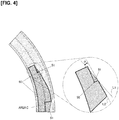
- Figure 4 illustrates a modified example of a case in which the current travelable area C is calculated.
- the steps (inner corner portions 50) that are generated when the first area A and the second area B are added are compensated for.
- the angle ⁇ formed between a boundary line L1, which is formed by a compensating portion 51, and a boundary line L2, which is adjacent to the compensating portion 51 is set to become shallower as the vehicle speed of the host vehicle 10 increases.
- the compensation process described above can be executed for all the steps (inner corner portions 50) that are generated when the first area A and the second area B are added, as illustrated in Figure 4 , but are executed at least with respect to the steps that are present in the direction of travel of the host vehicle 10.
- the target travel trajectory T of the host vehicle 10 generated within the travelable area C can be made smoother.
- the discomfort experienced by the senate when the target travel trajectory T shifts in the lateral direction increases as the vehicle speed of the host vehicle 10 increases.
- Figure 5 shows the same situation as that shown in Figure 3 .
- the trajectory generation unit 303 generates the target travel trajectory T in the central region of the travelable area C at that point in time, as illustrated in Figure 5 .
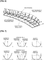
- a risk potential of the host vehicle 10 with respect to obstacles is defined for each point within the travelable area C, and the travel trajectory for which this risk potential becomes the minimum value is set as the target travel trajectory T, as illustrated in Figures 6 and 7 .
- the risk potential value at the left and right boundaries of the travelable area C is set to 1 (maximum value), and the risk potential value at the center of the travelable area C with respect to the vehicle width direction is set to 0 (minimum value).
- the trajectory generation unit 303 takes into consideration all of the risk potentials for each point within the travelable area C and determines the trajectory for which the sum of the risk potential values becomes smallest by means of a known optimization algorithm (for example, a least squares method).
- the risk potential is not limited to being defined by a quadratic function, but may also be defined by a quartic function, as is illustrated in Figure 7 .
- the risk potential value may be set to the minimum value (constant value) when within a set range from the center of the travelable area C with respect to the vehicle width direction.
- the function defining the risk potential it is not necessary for the function defining the risk potential to be symmetrical; the value of the risk potential may be different between left and right depending on the travel path of the host vehicle 10. For example, when the host vehicle 10 is traveling in the leftmost lane of a three-lane road with respect to the direction of travel, the risk that the host vehicle 10 will deviate from the road can be reduced by setting the risk potential value on the left side higher.
- the vertical axis represents the curvature of the travel trajectory of the host vehicle 10
- the horizontal axis represents time.
- the behavior when the vehicle travel control of the first embodiment is executed is indicated by the solid line
- the behavior when the control disclosed in Patent Document 1 is executed is indicated by the one-dotted chain line.
- Figure 9 is an explanatory view for explaining another modified example of the travelable area calculation process according to the first embodiment.
- the vehicle width direction of the travelable area C is reduced in size by half (W/2) of the vehicle width W of the host vehicle 10 from each of the left and right boundaries.
- the target travel trajectory T is generated taking into consideration the vehicle width W of the host vehicle 10 such that the host vehicle 10 can reliably travel within the travelable area C.
- the target travel trajectory T should not be generated within the range of half (W/2) of the vehicle width from the left and right boundaries of the travelable area C. Therefore, in this modified example, when the target travel trajectory T is generated, the areas corresponding to half (W/2) of the vehicle width W of the host vehicle 10 from the left and right boundaries of the travelable area C in the vehicle width direction are deleted in advance. As a result, it is possible to reduce the calculation processing load on the trajectory generation unit 303.
- the currently travelable area C is set taking into account the second area B, which is the previous travelable area. Therefore, it is possible to suppress a large change in the travelable area C and to suppress the behavior of the host vehicle 10 from changing significantly, even when the preceding vehicle changes over.
- the vehicle travel control system according to the second embodiment has the same configuration as the vehicle travel control system 1 according to the first embodiment, so that a detailed description will be omitted.
- Figure 10 is a flow chart illustrating the vehicle travel control process of the second embodiment that is executed by the vehicle control calculator 30 according to the second embodiment.
- the flow chart illustrated in Figure 10 is executed when a start condition for the preceding vehicle following control is satisfied, in the same manner as Figure 2 .
- Step S54 an area obtained by expanding the second area B set in Step S53 by a prescribed width in the vehicle width direction is defined as the virtual second area B'.
- Step S55 the current travelable area C is calculated based on the first area A calculated in Step S52, the second area B set in Step S53, and the virtual second area B' defined in Step S54. Specifically, only the area of the first area A that overlaps with the virtual second area B' (indicated as area A & B' in Figure 11 ) is added to the second area B to set the current travelable area C, as illustrated in Figure 11 .
- the currently travelable area C can be ultimately set in the manner described above; thus, the process thereof is not limited to the foregoing.
- the first area A and the second area B may be added first in the same manner as in the first embodiment, and an area of the first area A that does not overlap the virtual second area B' (area other than A & B') may be deleted.
- Steps S56 to S58 the same process as that from Steps S35 to S37 in Figure 2 is executed. In addition, the process described above is repeated as long as the result of Step S58 is negative.
- Step S53 the area indicated as area C in Figure 11 is set as the second area B (Step S53), and an area obtained by expanding this area by a prescribed width is defined as the virtual second area B' (Step S54). Therefore, by repeatedly executing the process of Figure 10 , the same area as the travelable area C of the first embodiment, which was explained with reference to Figures 2 , 3 , etc., is ultimately generated as the travelable area C.
- the object detection sensor 21 is not limited thereto.
- the object detection sensor may be a sensor that detects an object based on an image in front of the vehicle captured by means of a camera.
- Vehicle travel control system 10 Host vehicle, 100 Preceding vehicle, 110 New preceding vehicle, 21 Object detection sensor (detection unit), 24 Object recognition calculator, 30 Vehicle control calculator (controller), 301 Travelable area calculation unit (calculation unit, setting unit, area defining unit), 303 Trajectory generation unit (generation unit)
Landscapes
- Engineering & Computer Science (AREA)
- Physics & Mathematics (AREA)
- Automation & Control Theory (AREA)
- Transportation (AREA)
- Mechanical Engineering (AREA)
- General Physics & Mathematics (AREA)
- Mathematical Physics (AREA)
- Control Of Driving Devices And Active Controlling Of Vehicle (AREA)
- Traffic Control Systems (AREA)
- Control Of Position, Course, Altitude, Or Attitude Of Moving Bodies (AREA)
Abstract
Description
- The present disclosure relates to a vehicle travel control method and a vehicle travel control device for controlling a host vehicle so as to follow a preceding vehicle.
- When a host vehicle is controlled so as to follow a preceding vehicle, if the preceding vehicle to be followed changes over due to a lane change or another vehicle cutting in, the control target value changes significantly, and there is the risk of the vehicle behavior becoming unstable.
- Accordingly, in the technique disclosed in Patent Document 1 (Japanese Laid-Open Patent Application No.
2007-176290 - In the case of the technique disclosed in
Patent Document 1, although it is possible to suppress the vehicle behavior from changing significantly, the ability to follow the preceding vehicle decreases. As a result, for example, if a cut-in occurs during travel on a curved path and the preceding vehicle changes over, the host vehicle cannot appropriately follow the preceding vehicle that is traveling on the curved path, and there is the risk that the host vehicle will deviate from the lane of travel. - Therefore, an object of the present disclosure is to realize a vehicle travel control with which it is possible to suppress the vehicle behavior from changing significantly and to ensure the ability to follow the preceding vehicle, when the preceding vehicle changes over.
- In order to realize the object described above, in the present disclosure, the following process is executed upon detecting a new preceding vehicle cutting in between the preceding vehicle and the host vehicle. That is, a first area where the host vehicle can possible travel is calculated from a travel trajectory of the new preceding vehicle; a travelable area of the host vehicle up to a previous time is set as a second area; and the first area and the second area are added to define the travelable area. Moreover, a target travel trajectory of the host vehicle is generated in the defined travelable area, and the host vehicle is controlled along the generated target travel trajectory.
- As a result, it is possible to suppress the vehicle behavior from changing significantly, even when the preceding vehicle changes over. It is also possible to ensure the ability to follow the preceding vehicle.
-
- [
Figure 1 ] is a block diagram illustrating a schematic overview of a vehicle travel control system to which is applied a vehicle travel control method and a vehicle travel control device according to a first embodiment. - [
Figure 2 ] is a flow chart illustrating a vehicle travel control process of the first embodiment that is executed by a vehicle control calculator. - [
Figure 3 ] is an explanatory view for explaining a travelable area calculation process of the first embodiment. - [
Figure 4 ] is an explanatory view for explaining a modified example of the travelable area calculation process of the first embodiment. - [
Figure 5 ] is an explanatory view for explaining a travel trajectory generation process of the first embodiment. - [
Figure 6 ] is an explanatory view for explaining a travel trajectory generation process of the first embodiment. - [
Figure 7 ] is an explanatory view for explaining a modified example of the travel trajectory generation process of the first embodiment. - [
Figure 8 ] is an explanatory view illustrating an effect of the vehicle travel control of the first embodiment. - [
Figure 9 ] is an explanatory view for explaining another modified example of the travelable area calculation process of the first embodiment. - [
Figure 10 ] is a flow chart illustrating the vehicle travel control process of a second embodiment that is executed by the vehicle control calculator. - [
Figure 11 ] is an explanatory view for explaining the travelable area calculation process of the second embodiment. - An embodiment for realizing a vehicle travel control method and a vehicle travel control device according to the present disclosure will be described below based on the embodiments illustrated in the drawings.
-
Figure 1 is a block diagram schematically illustrating a vehicletravel control system 1 according to the first embodiment. The vehicletravel control system 1 shown inFigure 1 comprises anobject detection sensor 21, awheel speed sensor 22, ayaw rate sensor 23, anobject recognition calculator 24, avehicle control calculator 30, and anactuator 40. The vehicletravel control system 1 is a system that is mounted on ahost vehicle 10. - The
object detection sensor 21 detects the presence/absence of an obstacle or a preceding vehicle that is present in the vicinity of thehost vehicle 10. Theobject detection sensor 21 is composed of a scanning laser radar, a millimeter wave radar, or the like. - The
wheel speed sensor 22 is provided on the left and right driven wheels of thehost vehicle 10 and detects the rotational speed of the driven wheels. The rotational speed detected by thewheel speed sensor 22 is used for calculating the vehicle speed and the direction of travel of thehost vehicle 10. In addition, theyaw rate sensor 23 detects rotational angular velocity of thehost vehicle 10. The rotational angular velocity detected by theyaw rate sensor 23 is used for calculating the bearing of thehost vehicle 10. - The
object recognition calculator 24 detects the position of an object detected by theobject detection sensor 21 and determines whether the detected object is a preceding vehicle based on the size of the object, the relative speed with respect to thehost vehicle 10, and the like. During detection of a preceding vehicle, the object recognition calculator also labels the preceding vehicle. Thus, it is possible detect a changeover of the preceding vehicle when a different vehicle cuts in between the preceding vehicle and thehost vehicle 10, or when the preceding vehicle changes lanes. Theobject recognition calculator 24 calculates the vehicle speed of the detected preceding vehicle, as well as an inter-vehicular distance between the preceding vehicle and thehost vehicle 10 in order to realize the preceding vehicle following control. - The
vehicle control calculator 30 comprises a travelablearea calculation unit 301, amemory 302, atrajectory generation unit 303, and atravel control unit 304. The travelablearea calculation unit 301 calculates an area where thehost vehicle 10 can possibly travel based on the calculation result of theobject recognition calculator 24 and the detection results of thewheel speed sensor 22 and theyaw rate sensor 23. - The travelable area calculated by the travelable
area calculation unit 301 is stored in thememory 302 and transmitted to thetrajectory generation unit 303. Thetrajectory generation unit 303 generates a target travel trajectory T of thehost vehicle 10 within the received travelable area. - The target travel trajectory T generated by the
trajectory generation unit 303 is transmitted to thetravel control unit 304. Thetravel control unit 304 calculate the respective control amount for steering, accelerator, brake, etc. (none shown), such that thehost vehicle 10 can travel along the received target travel trajectory T. In addition, the travel control unit drives theactuator 40 based on the calculated control amounts. Although not shown, theactuator 40 is composed of a steering actuator, a drive actuator, a braking actuator, and the like. -
Figure 2 is a flow chart illustrating a vehicle travel control process of the first embodiment that is executed by the vehicle control calculator 30 (more precisely, by a processor incorporated in the vehicle control calculator 30). The flow chart illustrated inFigure 2 is executed when a start condition for the preceding vehicle following control is satisfied. Whether the start condition for the preceding vehicle following control has been satisfied is determined when the preceding vehicle is present and, for example, based on an ON/OFF state of an execution switch for the preceding vehicle following control that is provided in the driver's seat of thehost vehicle 10, or on a traffic condition. - First, in Step S31, the preceding vehicle is detected by means of the
object detection sensor 21 and theobject recognition calculator 24. - In Step S32, the travelable
area calculation unit 301 calculates the travelable area present between thehost vehicle 10 and the preceding vehicle detected in Step S31 as a first area A. Specifically, the travel trajectory on which the preceding vehicle actually travels between the current position of the host vehicle and the current position of the preceding vehicle is calculated as the first area A. This is because the area based on the trajectory on which the preceding vehicle has already traveled also can be determined as travelable for thehost vehicle 10. The first area may be the travel trajectory itself (that is, corresponding only to the width of the preceding vehicle), an area in which the travel trajectory is expanded to the width of the travel lane, or be set to an intermediate width therebetween. - In Step S33, the travelable
area calculation unit 301 sets the travelable area calculated up to a previous time as a second area B. That is, the entire area that is determined to be travelable in a process loop immediately before the current process loop is read from thememory 302 and is set as the second area B described above. - In addition, in the process of Step S33 of the first embodiment, the first and second areas, etc., are calculated based on relative coordinates with the
host vehicle 10 as the origin. Thus, in Step S33, when the travelable area of thehost vehicle 10 up to the previous time is set as the second area B, a coordinate transform that corresponds to the movement amount and movement direction of thehost vehicle 10 between the previous time and the current time is carried out. - The coordinate transform described above can be carried out by calculating the movement amount and the movement direction of the
host vehicle 10 by means of dead reckoning from the outputs of thewheel speed sensor 22 and theyaw rate sensor 23. Alternatively, the coordinate transform may be carried out by calculating the movement amount and the movement direction of thehost vehicle 10 by means of odometry from the output of thewheel speed sensor 22. - Next, in Step S34, the first area A calculated in Step S32 and the second area B calculated in Step S33 are added to calculate the travelable area C. That is, the travelable area C indicates the entire area that can be determined as currently travelable. The calculation result of Step S34 is stored in the
memory 302 and used when the second area B is set in the subsequent process loop. - In Step S35, the
trajectory generation unit 303 generates the target travel trajectory T of thehost vehicle 10 in a central region within the travelable area C calculated in Step S34. In the present disclosure, the central region refers to a region obtained by expanding a center line of the travelable area C by a prescribed amount (for example, by half the vehicle width of the host vehicle 10). - In Step S36, a follow control that controls the travel of the
host vehicle 10 along the target travel trajectory T generated in Step S35 is carried out. Specifically, as described above, thetravel control unit 304 calculates the control amounts, such as the steering, in accordance with the target travel trajectory T and drives theactuator 40 based on the calculated control amounts to thereby achieve the follow control. - Next, in Step S37, it is determined whether the follow control should be stopped. If the result is negative, the process returns to Step S31 and repeats the process described above. If the result is affirmative, the present vehicle travel control process is ended. Whether the follow control should be stopped is determined based on whether the start condition for the preceding vehicle following control is satisfied.
- If a changeover of the preceding vehicle occurs during execution of the flow chart of
Figure 2 , it is detected that a changeover of the preceding vehicle occurred by theobject recognition calculator 24 in Step S31, and, in the subsequent Step S32, the first area A is calculated based on the new preceding vehicle. - The processing of the travelable
area calculation unit 301 described above (Steps S32 to S34) will be described with reference toFigures 3 and4 . -
Figure 3 illustrates the situation around the time that a cut-in of a preceding vehicle occurs, arranged in chronological order. Before the cut-in of a preceding vehicle occurs (Figure 3 , left), the travelablearea calculation unit 301 calculates the first area A based on the travel trajectory of the current precedingvehicle 100. If there is a travelable area that was calculated in the previous process loop, said travelable area is set as the second area B, and the first area A and the second area B are added to calculate the current travelable area C. Since the situation shown on the left side ofFigure 3 indicates the first process of executing the flow chart ofFigure 2 , the second area B is not present. Therefore, the first area A becomes the current travelable area C. - Thereafter, if another vehicle (new preceding vehicle 110) cuts in between the
host vehicle 10 and the preceding vehicle 100 (Figure 3 , middle), the travelablearea calculation unit 301 calculates a new first area A based on the travel trajectory of the new precedingvehicle 110. In addition, the travelablearea calculation unit 301 sets the area that was the travelable area of thehost vehicle 10 up to the previous time, calculated based on the travel trajectory of the precedingvehicle 100, as the second area B, and adds the first area A and the second area B to calculate the current travelable area C. - In the subsequent process loop (
Figure 3 , right), the travelablearea calculation unit 301 similarly calculates the first area A based on the current position of the new precedingvehicle 110 and the travel trajectory thereof, sets the previous travelable area as the second area B, and adds the first area A and the second area B to calculate the current travelable area C. - As described above, in this embodiment, when the preceding
vehicle 100 is changed over to the new precedingvehicle 110, the current travelable area C is set by taking into account the second area B, which is the previous travelable area. Accordingly, it is possible to suppress a large change in the travelable area C and to suppress the behavior of thehost vehicle 10 from changing significantly, even when the preceding vehicle changes over. Moreover, since the gain in the follow control is not changed, the ability to follow the preceding vehicle does not decrease. -
Figure 4 illustrates a modified example of a case in which the current travelable area C is calculated. In the modified example shown inFigure 4 , the steps (inner corner portions 50) that are generated when the first area A and the second area B are added are compensated for. Here, in the compensated travelable area C, the angle α formed between a boundary line L1, which is formed by a compensatingportion 51, and a boundary line L2, which is adjacent to the compensatingportion 51, is set to become shallower as the vehicle speed of thehost vehicle 10 increases. - The compensation process described above can be executed for all the steps (inner corner portions 50) that are generated when the first area A and the second area B are added, as illustrated in
Figure 4 , but are executed at least with respect to the steps that are present in the direction of travel of thehost vehicle 10. - By compensating for the steps (inner corner portions 50) of the travelable area C, as in this modified example, the target travel trajectory T of the
host vehicle 10 generated within the travelable area C can be made smoother. - Also, the discomfort experienced by the senate when the target travel trajectory T shifts in the lateral direction increases as the vehicle speed of the
host vehicle 10 increases. Thus, it is possible to reduce the amount of shift of the target travel trajectory T in the lateral direction, and to thereby reduce the discomfort described above, by setting the above-described angle α smaller as the vehicle speed of thehost vehicle 10 increases. - Next, a trajectory generation process executed by the
trajectory generation unit 303 described above will be described with reference toFigures 5 to 7 .Figure 5 shows the same situation as that shown inFigure 3 . - The
trajectory generation unit 303 generates the target travel trajectory T in the central region of the travelable area C at that point in time, as illustrated inFigure 5 . Specifically, a risk potential of thehost vehicle 10 with respect to obstacles is defined for each point within the travelable area C, and the travel trajectory for which this risk potential becomes the minimum value is set as the target travel trajectory T, as illustrated inFigures 6 and 7 . - For example, if the risk potential is defined using a quadratic function, the risk potential value at the left and right boundaries of the travelable area C is set to 1 (maximum value), and the risk potential value at the center of the travelable area C with respect to the vehicle width direction is set to 0 (minimum value). The
trajectory generation unit 303 takes into consideration all of the risk potentials for each point within the travelable area C and determines the trajectory for which the sum of the risk potential values becomes smallest by means of a known optimization algorithm (for example, a least squares method). - The risk potential is not limited to being defined by a quadratic function, but may also be defined by a quartic function, as is illustrated in
Figure 7 . In addition, the risk potential value may be set to the minimum value (constant value) when within a set range from the center of the travelable area C with respect to the vehicle width direction. Moreover, it is not necessary for the function defining the risk potential to be symmetrical; the value of the risk potential may be different between left and right depending on the travel path of thehost vehicle 10. For example, when thehost vehicle 10 is traveling in the leftmost lane of a three-lane road with respect to the direction of travel, the risk that thehost vehicle 10 will deviate from the road can be reduced by setting the risk potential value on the left side higher. - Next, a quantitative effect of the vehicle travel control according to the first embodiment will be described with reference to
Figure 8 . InFigure 8 , the vertical axis represents the curvature of the travel trajectory of thehost vehicle 10, and the horizontal axis represents time. The behavior when the vehicle travel control of the first embodiment is executed is indicated by the solid line, the behavior when a normal follow control is executed as is indicated by the broken line, and the behavior when the control disclosed inPatent Document 1 is executed is indicated by the one-dotted chain line. - As described above, according to the control disclosed in
Patent Document 1, because the gain of the follow control is set low, it is possible to suppress the vehicle behavior from changing significantly when the preceding vehicle changes over. However, as indicated by the circled portion inFigure 8 , the responsiveness decreases relative to the normal follow control. In contrast, when the vehicle travel control according to the first embodiment is executed, a reduction in the responsiveness as seen above does not occur. Moreover, as with the technique disclosed inPatent Document 1, it is possible to suppress the behavior of thehost vehicle 10 from changing significantly when the preceding vehicle changes over. -
Figure 9 is an explanatory view for explaining another modified example of the travelable area calculation process according to the first embodiment. In this modified example, after the current travelable area C is calculated, the vehicle width direction of the travelable area C is reduced in size by half (W/2) of the vehicle width W of thehost vehicle 10 from each of the left and right boundaries. - That is, when the target travel trajectory T is generated, the target travel trajectory T is generated taking into consideration the vehicle width W of the
host vehicle 10 such that thehost vehicle 10 can reliably travel within the travelable area C. In other words, the target travel trajectory T should not be generated within the range of half (W/2) of the vehicle width from the left and right boundaries of the travelable area C. Therefore, in this modified example, when the target travel trajectory T is generated, the areas corresponding to half (W/2) of the vehicle width W of thehost vehicle 10 from the left and right boundaries of the travelable area C in the vehicle width direction are deleted in advance. As a result, it is possible to reduce the calculation processing load on thetrajectory generation unit 303. - The effects listed below can be obtained with the vehicle travel control method and the vehicle travel control device according to the first embodiment described above.
- (1) A vehicle travel control method for controlling a
host vehicle 10 so as to follow a precedingvehicle 100 comprises: calculating a first area A where thehost vehicle 10 can possibly travel from a travel trajectory of a new preceding vehicle 110 (Step S32), upon when detecting the new precedingvehicle 110 cutting in between the precedingvehicle 100 and the host vehicle 10 (Step S31); setting a travelable area of thehost vehicle 10 up to a previous time as a second area B (Step S33); adding the first area A and the second area B to define the travelable area C (Step S34); generating a target travel trajectory T of thehost vehicle 10 within the defined travelable area C (Step S35); and controlling thehost vehicle 10 along the generated target travel trajectory T (Step S36).
That is, when the precedingvehicle 100 is changed over to the new precedingvehicle 110, the current travelable area C is set taking into account the second area B, which is the previous travelable area. Thus, it is possible to suppress a large change in the travelable area C and to suppress the behavior of thehost vehicle 10 from changing significantly, even when the preceding vehicle changes over. - (2) In addition, the target travel trajectory T is generated in a central region within the travelable area C (Step S35,
Figures 5 to 7 ). Therefore, in addition to the effect of (1), it is possible to generate a smooth target travel trajectory T. - (3) In addition, an
inner corner portion 50 of the defined travelable area C is compensated by a compensatingportion 51, and the target travel trajectory T is generated within the compensated travelable area C (Steps S34 to S35,Figure 4 ). Therefore, it is possible to eliminate a step (inner corner portion 50) within the travelable area C and to generate a smoother target travel trajectory T. - (4) In addition, the compensation is set such that, in the compensated travelable area C, an angle α formed between a boundary line L1, which is formed by the compensating
portion 51, and a boundary line L2, which is adjacent to the compensatingportion 51, becomes smaller as the vehicle speed of thehost vehicle 10 increases (Steps S34,Figure 4 ). That is, since the discomfort that the passenger experiences with respect to a behavior in the lateral direction increases as the vehicle speed of thehost vehicle 10 increases, the expansion of the travelable area C in the lateral direction due to the compensatingportion 51 is configured to decrease as the vehicle speed of thehost vehicle 10 increases. As a result, in addition to the effect of (3), it is possible to reduce the amount of shift of the target travel trajectory T in the lateral direction, and to thereby reduce the discomfort described above. - (5) In addition, a risk potential with respect to obstacles in the vicinity of the
host vehicle 10 is defined based on boundaries in the travelable area C in the vehicle width direction of thehost vehicle 10, and a path in which the defined risk potential becomes smallest is set as the target travel trajectory T (Step S35,Figures 6 and 7 ). Therefore, in addition to the effects of (1) to (4), it is possible to generate a smoother target travel trajectory T. - (6) In addition, the risk potential is defined using a quadratic function, the risk potential value at the boundaries in the vehicle width direction is set to 1, and the risk potential value at the center with respect to the vehicle width direction is set to 0 (Step S35,
Figures 6 and 7 ). Therefore, in addition to the effect of (5), it is possible to more reliably prevent thehost vehicle 10 from deviating from the travelable area C and to further simplify the calculation process for generating the target travel trajectory T. - (7) In addition, the risk potential is defined using a quadratic function, and a path with which the risk potential becomes smallest is determined based on the least squares method (Step S35,
Figures 6 and 7 ). Therefore, in addition to the effects of (5) and (6), it becomes unnecessary to repeatedly carry out the calculation and a faster computation process can be realized. - (8) In addition, in a vehicle travel control device (the vehicle travel control system 1) that has a controller (the vehicle control calculator 30) that controls a
host vehicle 10 along a target travel trajectory T generated so as to follow a preceding vehicle, thecontroller 30 comprises: a detection unit (theobject detection sensor 21, the object recognition calculator 24) that detects whether a new precedingvehicle 110 cutting in has occurred between the precedingvehicle 100 and thehost vehicle 10; a calculation unit that calculates a first area A where thehost vehicle 10 can possibly travel from a travel trajectory of the new precedingvehicle 110; a setting unit (the travelable area calculation unit 301) that sets a travelable area up to a previous time as a second area B; an area defining unit (the travelable area calculation unit 301) for adding the first area A and the second area B to define the travelable area C (the travelable area calculation unit 301); and a generation unit (the trajectory generation unit 303) for generating a target travel trajectory T of thehost vehicle 10 within the travelable area C. - That is, when the preceding
vehicle 100 is changed over to the new precedingvehicle 110, the currently travelable area C is set taking into account the second area B, which is the previous travelable area. Therefore, it is possible to suppress a large change in the travelable area C and to suppress the behavior of thehost vehicle 10 from changing significantly, even when the preceding vehicle changes over. - Next, the vehicle travel control method and the vehicle travel control device according to a second embodiment of the present invention will be described with reference to
Figures 10 and11 . The vehicle travel control system according to the second embodiment has the same configuration as the vehicletravel control system 1 according to the first embodiment, so that a detailed description will be omitted. -
Figure 10 is a flow chart illustrating the vehicle travel control process of the second embodiment that is executed by thevehicle control calculator 30 according to the second embodiment. The flow chart illustrated inFigure 10 is executed when a start condition for the preceding vehicle following control is satisfied, in the same manner asFigure 2 . - First, from Steps S51 to S53, the same process as that from Steps S31 to S33 in
Figure 2 is executed. Next, a virtual second area B' is defined in Step S54. Specifically, an area obtained by expanding the second area B set in Step S53 by a prescribed width in the vehicle width direction is defined as the virtual second area B'. - In Step S55, the current travelable area C is calculated based on the first area A calculated in Step S52, the second area B set in Step S53, and the virtual second area B' defined in Step S54. Specifically, only the area of the first area A that overlaps with the virtual second area B' (indicated as area A & B' in
Figure 11 ) is added to the second area B to set the current travelable area C, as illustrated inFigure 11 . - It suffices if the currently travelable area C can be ultimately set in the manner described above; thus, the process thereof is not limited to the foregoing. For example, the first area A and the second area B may be added first in the same manner as in the first embodiment, and an area of the first area A that does not overlap the virtual second area B' (area other than A & B') may be deleted.
- In the subsequent Steps S56 to S58, the same process as that from Steps S35 to S37 in
Figure 2 is executed. In addition, the process described above is repeated as long as the result of Step S58 is negative. - That is, in the case of the example shown in
Figure 11 , in the subsequent process loop, the area indicated as area C inFigure 11 is set as the second area B (Step S53), and an area obtained by expanding this area by a prescribed width is defined as the virtual second area B' (Step S54). Therefore, by repeatedly executing the process ofFigure 10 , the same area as the travelable area C of the first embodiment, which was explained with reference toFigures 2 ,3 , etc., is ultimately generated as the travelable area C. - The effects listed below can be obtained with the vehicle travel control method and the vehicle travel control device according to the second embodiment.
- (9) A virtual second area B' obtained by expanding the second area B in the vehicle width direction by a prescribed width is defined (Step S54), and only an area of the first area A that overlaps the virtual second area B' (area A & B') is added to the second area B to define the travelable area C (Step S55). That is, the currently travelable area C is not expanded by more than the prescribed width from the second area B', which is the previous travelable area. Accordingly, it is possible to further suppress a large change in the travelable area C, and thus to further suppress the behavior of the
host vehicle 10 from changing significantly, even when the preceding vehicle changes over. - (10) In addition, the first area A and the second area B are added to define the travelable area C, a virtual second area B' obtained by expanding the second area B by a prescribed width is defined, and the area of the defined travelable area C that does not overlap the virtual second area B' can be deleted. The same effect as (8) can be obtained in this case as well.
- The vehicle travel control method and the vehicle travel control device of the present invention were described above based on the first and second embodiments, but specific configurations thereof are not limited to these embodiments, and various design modifications and additions can be made without departing from the scope of the invention according to each claim of the Claims.
- In the first and second embodiments, a scanning laser radar and a millimeter wave radar were given as examples of the
object detection sensor 21. However, theobject detection sensor 21 is not limited thereto. For example, the object detection sensor may be a sensor that detects an object based on an image in front of the vehicle captured by means of a camera. - 1 Vehicle travel control system, 10 Host vehicle, 100 Preceding vehicle, 110 New preceding vehicle, 21 Object detection sensor (detection unit), 24 Object recognition calculator, 30 Vehicle control calculator (controller), 301 Travelable area calculation unit (calculation unit, setting unit, area defining unit), 303 Trajectory generation unit (generation unit)
Claims (10)
- A vehicle travel control method for controlling a host vehicle so as to follow a preceding vehicle, comprising:calculating a first area where the host vehicle can possibly travel from a travel trajectory of the new preceding vehicle upon detecting a new preceding vehicle cutting in between the preceding vehicle and the host vehicle;setting a travelable area of the host vehicle up to a previous time as a second area;defining the travelable area by adding the first area and the second area;generating a target travel trajectory of the host vehicle within the defined travelable area; andcontrolling the host vehicle along the generated target travel trajectory.
- The vehicle travel control method according to claim 1, wherein
the target travel trajectory is generated in a central region within the travelable area. - The vehicle travel control method according to claim 1 or 2, wherein
an inner corner portion of the defined travelable area is compensated by a compensating portion, and
the target travel trajectory is generated within the compensated travelable area. - The vehicle travel control method according to claim 3, wherein
compensation of the compensated travelable area is performed such that an angle formed between a boundary line of the compensating portion and a boundary line adjacent the compensating portion becomes shallower as a vehicle speed of the host vehicle increases. - The vehicle travel control method according to any one of claims 1 to 4, wherein
a risk potential with respect to obstacles in a vicinity of the host vehicle is defined based on boundaries in the travelable area in a vehicle width direction of the host vehicle, and
a path is set as the target travel trajectory in which the defined risk potential becomes smallest. - The vehicle travel control method according to claim 5, wherein
the risk potential is defined using a quadratic function, a risk potential value at the boundaries in the vehicle width direction is set to 1, and a risk potential value at a center with respect to the vehicle width direction is set to 0. - The vehicle travel control method according to claim 5 or 6, wherein
the risk potential is defined using a quadratic function, and the path with which the risk potential becomes smallest is determined based on a least squares method. - The vehicle travel control method according to any one of claims 1 to 7, wherein
a virtual second area obtained by expanding the second area in a vehicle width direction by a prescribed width is defined, and
only an area of the first area that overlaps the virtual second area is added to the second area to define the travelable area. - The vehicle travel control method according to any one of claims 1 to 7, wherein
the first area and the second area are added to define the travelable area,
a virtual second area obtained by expanding the second area in a vehicle width direction by a prescribed width is defined, and
an area of the defined travelable area that does not overlap the virtual second area is deleted. - A vehicle travel control device comprising:a controller that controls a host vehicle along a target travel trajectory generated so as to follow a preceding vehicle, whereinthe controller comprises:a detection unit that detects whether a new preceding vehicle cutting in has occurred between the preceding vehicle and the host vehicle;a calculation unit that calculates a first area where the host vehicle can possibly travel from a travel trajectory of the new preceding vehicle;a setting unit that sets a travelable area up to a previous time as a second area;an area defining unit that define a travelable area by adding the first area and the second area; anda generation unit that generates a target travel trajectory of the host vehicle within the travelable area.
Applications Claiming Priority (1)
| Application Number | Priority Date | Filing Date | Title |
|---|---|---|---|
| PCT/JP2016/076036 WO2018042671A1 (en) | 2016-09-05 | 2016-09-05 | Vehicle travel control method and vehicle travel control device |
Publications (2)
| Publication Number | Publication Date |
|---|---|
| EP3509051A1 true EP3509051A1 (en) | 2019-07-10 |
| EP3509051A4 EP3509051A4 (en) | 2019-09-25 |
Family
ID=61300441
Family Applications (1)
| Application Number | Title | Priority Date | Filing Date |
|---|---|---|---|
| EP16915226.1A Ceased EP3509051A4 (en) | 2016-09-05 | 2016-09-05 | VEHICLE DISPLACEMENT CONTROL METHOD AND VEHICLE DISPLACEMENT CONTROL DEVICE |
Country Status (10)
| Country | Link |
|---|---|
| US (1) | US10997862B2 (en) |
| EP (1) | EP3509051A4 (en) |
| JP (1) | JP6460288B2 (en) |
| KR (1) | KR20190031331A (en) |
| CN (1) | CN109690649B (en) |
| BR (1) | BR112019004101A2 (en) |
| CA (1) | CA3035856A1 (en) |
| MX (1) | MX2019002499A (en) |
| RU (1) | RU2706750C1 (en) |
| WO (1) | WO2018042671A1 (en) |
Families Citing this family (20)
| Publication number | Priority date | Publication date | Assignee | Title |
|---|---|---|---|---|
| US8825265B1 (en) * | 2012-03-16 | 2014-09-02 | Google Inc. | Approach for consolidating observed vehicle trajectories into a single representative trajectory |
| US11572099B2 (en) | 2018-04-27 | 2023-02-07 | Honda Motor Co., Ltd. | Merge behavior systems and methods for merging vehicles |
| US11117584B2 (en) * | 2018-04-27 | 2021-09-14 | Honda Motor Co., Ltd. | Merge behavior systems and methods for mainline vehicles |
| KR102628282B1 (en) * | 2018-10-10 | 2024-01-24 | 현대자동차주식회사 | Vehicle and control method thereof |
| JP2020160914A (en) * | 2019-03-27 | 2020-10-01 | 株式会社豊田自動織機 | Object detector |
| JP7251294B2 (en) * | 2019-04-25 | 2023-04-04 | 株式会社アドヴィックス | Vehicle travel control device |
| JP7333195B2 (en) * | 2019-05-15 | 2023-08-24 | 株式会社Subaru | Automated driving support system |
| CN112230642B (en) * | 2019-06-29 | 2022-01-11 | 华为技术有限公司 | Road travelable area reasoning method and device |
| CN111222579B (en) * | 2020-01-09 | 2023-10-03 | 北京百度网讯科技有限公司 | Cross-camera obstacle association methods, devices, equipment, electronic systems and media |
| JP7346722B2 (en) * | 2020-04-06 | 2023-09-19 | 日産自動車株式会社 | Driving support method and driving support device |
| CN111649739B (en) * | 2020-06-02 | 2023-09-01 | 阿波罗智能技术(北京)有限公司 | Positioning method and device, self-driving vehicle, electronic device and storage medium |
| JP7509491B2 (en) * | 2020-06-11 | 2024-07-02 | 株式会社Subaru | Vehicle driving support device |
| CN112677972A (en) * | 2020-12-25 | 2021-04-20 | 际络科技(上海)有限公司 | Adaptive cruise method and apparatus, device and medium |
| US11880203B2 (en) * | 2021-01-05 | 2024-01-23 | Argo AI, LLC | Methods and system for predicting trajectories of uncertain road users by semantic segmentation of drivable area boundaries |
| US11958503B2 (en) * | 2021-04-16 | 2024-04-16 | Motional Ad Llc | Techniques for navigating an autonomous vehicle based on perceived risk |
| CN113119978A (en) * | 2021-05-10 | 2021-07-16 | 蔚来汽车科技(安徽)有限公司 | Lane edge extraction method and apparatus, automatic driving system, vehicle, and storage medium |
| JP7670637B2 (en) * | 2022-02-25 | 2025-04-30 | トヨタ自動車株式会社 | Information display device and information display program |
| JP7385697B2 (en) * | 2022-03-29 | 2023-11-22 | 本田技研工業株式会社 | Vehicle control device, vehicle control method, and program |
| JP7843633B2 (en) * | 2022-03-31 | 2026-04-10 | 住友重機械工業株式会社 | Information processing device, information processing system, and information processing program |
| KR20240054006A (en) * | 2022-10-18 | 2024-04-25 | 현대자동차주식회사 | Apparatus and method for controlling vehicle |
Family Cites Families (14)
| Publication number | Priority date | Publication date | Assignee | Title |
|---|---|---|---|---|
| JPS56159275A (en) | 1980-05-14 | 1981-12-08 | Dainippon Printing Co Ltd | Reversible temperature indicating composition |
| US7266453B2 (en) * | 2003-08-22 | 2007-09-04 | Honda Motor Co., Ltd. | Vehicular object detection system, tracking control system, and vehicle control system |
| JP5042496B2 (en) | 2005-12-27 | 2012-10-03 | 富士重工業株式会社 | Driving assistance device |
| JP4169065B2 (en) * | 2006-02-13 | 2008-10-22 | 株式会社デンソー | Vehicle control device |
| JP2008027309A (en) | 2006-07-24 | 2008-02-07 | Sumitomo Electric Ind Ltd | Collision determination system and collision determination method |
| JP2008117073A (en) * | 2006-11-01 | 2008-05-22 | Fuji Heavy Ind Ltd | Interrupting vehicle detection device |
| JP5696444B2 (en) * | 2009-12-24 | 2015-04-08 | 日産自動車株式会社 | Travel control device |
| JP5673597B2 (en) * | 2011-11-18 | 2015-02-18 | 株式会社デンソー | Vehicle behavior control device |
| DE102012005272A1 (en) * | 2012-02-20 | 2012-10-25 | Daimler Ag | Method for determining risk probability of situation between two vehicles, for issuing different driver warnings, involves determining space for maneuvering between vehicles for determining risk probability, based on size of each space |
| JP5981332B2 (en) * | 2012-12-21 | 2016-08-31 | 株式会社日本自動車部品総合研究所 | Travel route generator |
| JP5821917B2 (en) | 2013-09-20 | 2015-11-24 | トヨタ自動車株式会社 | Driving assistance device |
| JP6154348B2 (en) * | 2014-03-28 | 2017-06-28 | 株式会社Soken | Travel route generator |
| JP5991340B2 (en) | 2014-04-28 | 2016-09-14 | トヨタ自動車株式会社 | Driving assistance device |
| JP6507839B2 (en) * | 2015-05-19 | 2019-05-08 | 株式会社デンソー | Vehicle travel control device |
-
2016
- 2016-09-05 CA CA3035856A patent/CA3035856A1/en not_active Abandoned
- 2016-09-05 RU RU2019109971A patent/RU2706750C1/en active
- 2016-09-05 JP JP2018536676A patent/JP6460288B2/en not_active Expired - Fee Related
- 2016-09-05 CN CN201680088960.5A patent/CN109690649B/en not_active Expired - Fee Related
- 2016-09-05 MX MX2019002499A patent/MX2019002499A/en unknown
- 2016-09-05 BR BR112019004101A patent/BR112019004101A2/en not_active IP Right Cessation
- 2016-09-05 WO PCT/JP2016/076036 patent/WO2018042671A1/en not_active Ceased
- 2016-09-05 US US16/323,385 patent/US10997862B2/en not_active Expired - Fee Related
- 2016-09-05 EP EP16915226.1A patent/EP3509051A4/en not_active Ceased
- 2016-09-05 KR KR1020197007305A patent/KR20190031331A/en not_active Abandoned
Also Published As
| Publication number | Publication date |
|---|---|
| CN109690649A (en) | 2019-04-26 |
| CA3035856A1 (en) | 2018-03-08 |
| EP3509051A4 (en) | 2019-09-25 |
| WO2018042671A1 (en) | 2018-03-08 |
| US10997862B2 (en) | 2021-05-04 |
| RU2706750C1 (en) | 2019-11-20 |
| BR112019004101A2 (en) | 2019-05-28 |
| MX2019002499A (en) | 2019-07-18 |
| US20200388157A1 (en) | 2020-12-10 |
| JPWO2018042671A1 (en) | 2019-06-24 |
| CN109690649B (en) | 2021-03-16 |
| JP6460288B2 (en) | 2019-01-30 |
| KR20190031331A (en) | 2019-03-25 |
Similar Documents
| Publication | Publication Date | Title |
|---|---|---|
| US10997862B2 (en) | Vehicle travel control method and vehicle travel control device | |
| US11092967B2 (en) | Vehicle movement control device | |
| US11904937B2 (en) | Vehicle traveling controller | |
| JP7205768B2 (en) | Vehicle travel control device | |
| CN104973125B (en) | Evacuation auxiliary | |
| CN111845739B (en) | Vehicle travel control device | |
| JP7000765B2 (en) | Vehicle driving control device | |
| US11052925B2 (en) | Target vehicle speed generation method and target vehicle speed generation device for driving-assisted vehicle | |
| US8090517B2 (en) | Inter-vehicle distance maintenance supporting system and method | |
| US8190330B2 (en) | Model based predictive control for automated lane centering/changing control systems | |
| EP2712780B1 (en) | Method and apparatus for performing driving assistance | |
| JP5012849B2 (en) | Vehicle travel control device | |
| JP7200786B2 (en) | vehicle braking controller | |
| JP2009184675A (en) | Travel control device | |
| US20200391737A1 (en) | Target vehicle speed generation method and target vehicle speed generation device for driving assisted vehicle | |
| WO2019159562A1 (en) | Driving assistance device, driving assistance method, and driving assistance system | |
| JP5817097B2 (en) | Vehicle control device | |
| KR102279309B1 (en) | Vehicle safety control method according to failure to exchange driving control right | |
| US11634140B2 (en) | Vehicle control method and vehicle control device | |
| JP2017128178A (en) | Vehicular travel control device | |
| CN115071695A (en) | Automatic emergency braking control method and system for vehicle | |
| JP3870851B2 (en) | Lane departure prevention device | |
| JP2018127175A (en) | Deflection control device | |
| JP2005115816A (en) | Vehicle control device |
Legal Events
| Date | Code | Title | Description |
|---|---|---|---|
| STAA | Information on the status of an ep patent application or granted ep patent |
Free format text: STATUS: THE INTERNATIONAL PUBLICATION HAS BEEN MADE |
|
| PUAI | Public reference made under article 153(3) epc to a published international application that has entered the european phase |
Free format text: ORIGINAL CODE: 0009012 |
|
| STAA | Information on the status of an ep patent application or granted ep patent |
Free format text: STATUS: REQUEST FOR EXAMINATION WAS MADE |
|
| 17P | Request for examination filed |
Effective date: 20190326 |
|
| AK | Designated contracting states |
Kind code of ref document: A1 Designated state(s): AL AT BE BG CH CY CZ DE DK EE ES FI FR GB GR HR HU IE IS IT LI LT LU LV MC MK MT NL NO PL PT RO RS SE SI SK SM TR |
|
| AX | Request for extension of the european patent |
Extension state: BA ME |
|
| A4 | Supplementary search report drawn up and despatched |
Effective date: 20190822 |
|
| RIC1 | Information provided on ipc code assigned before grant |
Ipc: B60W 30/165 20120101ALI20190816BHEP Ipc: G08G 1/16 20060101AFI20190816BHEP |
|
| DAV | Request for validation of the european patent (deleted) | ||
| DAX | Request for extension of the european patent (deleted) | ||
| STAA | Information on the status of an ep patent application or granted ep patent |
Free format text: STATUS: EXAMINATION IS IN PROGRESS |
|
| 17Q | First examination report despatched |
Effective date: 20200702 |
|
| REG | Reference to a national code |
Ref country code: DE Ref legal event code: R003 |
|
| STAA | Information on the status of an ep patent application or granted ep patent |
Free format text: STATUS: THE APPLICATION HAS BEEN REFUSED |
|
| 18R | Application refused |
Effective date: 20211017 |