EP3508803A1 - Freezing apparatus - Google Patents
Freezing apparatus Download PDFInfo
- Publication number
- EP3508803A1 EP3508803A1 EP17846575.3A EP17846575A EP3508803A1 EP 3508803 A1 EP3508803 A1 EP 3508803A1 EP 17846575 A EP17846575 A EP 17846575A EP 3508803 A1 EP3508803 A1 EP 3508803A1
- Authority
- EP
- European Patent Office
- Prior art keywords
- refrigerant
- usage
- heat exchanger
- heat source
- connection state
- Prior art date
- Legal status (The legal status is an assumption and is not a legal conclusion. Google has not performed a legal analysis and makes no representation as to the accuracy of the status listed.)
- Withdrawn
Links
- 230000008014 freezing Effects 0.000 title 1
- 238000007710 freezing Methods 0.000 title 1
- 239000003507 refrigerant Substances 0.000 claims abstract description 454
- 238000010257 thawing Methods 0.000 claims abstract description 125
- 238000005057 refrigeration Methods 0.000 claims abstract description 104
- 230000006870 function Effects 0.000 claims abstract description 22
- 239000007788 liquid Substances 0.000 claims description 66
- 230000007423 decrease Effects 0.000 claims description 9
- 238000002347 injection Methods 0.000 description 29
- 239000007924 injection Substances 0.000 description 29
- 238000001816 cooling Methods 0.000 description 15
- 230000004048 modification Effects 0.000 description 13
- 238000012986 modification Methods 0.000 description 13
- 238000004891 communication Methods 0.000 description 10
- 238000011144 upstream manufacturing Methods 0.000 description 10
- 238000007906 compression Methods 0.000 description 6
- 238000006073 displacement reaction Methods 0.000 description 6
- 238000010586 diagram Methods 0.000 description 5
- 230000008859 change Effects 0.000 description 4
- 230000006835 compression Effects 0.000 description 4
- 230000005494 condensation Effects 0.000 description 4
- 238000009833 condensation Methods 0.000 description 4
- 230000003247 decreasing effect Effects 0.000 description 4
- 238000001514 detection method Methods 0.000 description 4
- 238000000034 method Methods 0.000 description 4
- QGZKDVFQNNGYKY-UHFFFAOYSA-N Ammonia Chemical compound N QGZKDVFQNNGYKY-UHFFFAOYSA-N 0.000 description 2
- ATUOYWHBWRKTHZ-UHFFFAOYSA-N Propane Chemical compound CCC ATUOYWHBWRKTHZ-UHFFFAOYSA-N 0.000 description 2
- 238000004378 air conditioning Methods 0.000 description 2
- 230000000694 effects Effects 0.000 description 2
- 238000002844 melting Methods 0.000 description 2
- 230000008018 melting Effects 0.000 description 2
- 230000009467 reduction Effects 0.000 description 2
- 229920006395 saturated elastomer Polymers 0.000 description 2
- 206010067482 No adverse event Diseases 0.000 description 1
- 229910021529 ammonia Inorganic materials 0.000 description 1
- 238000007599 discharging Methods 0.000 description 1
- 238000001704 evaporation Methods 0.000 description 1
- 238000010438 heat treatment Methods 0.000 description 1
- 239000000203 mixture Substances 0.000 description 1
- 239000001294 propane Substances 0.000 description 1
- 239000000243 solution Substances 0.000 description 1
- 231100000331 toxic Toxicity 0.000 description 1
- 230000002588 toxic effect Effects 0.000 description 1
Images



Classifications
-
- F—MECHANICAL ENGINEERING; LIGHTING; HEATING; WEAPONS; BLASTING
- F25—REFRIGERATION OR COOLING; COMBINED HEATING AND REFRIGERATION SYSTEMS; HEAT PUMP SYSTEMS; MANUFACTURE OR STORAGE OF ICE; LIQUEFACTION SOLIDIFICATION OF GASES
- F25B—REFRIGERATION MACHINES, PLANTS OR SYSTEMS; COMBINED HEATING AND REFRIGERATION SYSTEMS; HEAT PUMP SYSTEMS
- F25B49/00—Arrangement or mounting of control or safety devices
- F25B49/005—Arrangement or mounting of control or safety devices of safety devices
-
- F—MECHANICAL ENGINEERING; LIGHTING; HEATING; WEAPONS; BLASTING
- F25—REFRIGERATION OR COOLING; COMBINED HEATING AND REFRIGERATION SYSTEMS; HEAT PUMP SYSTEMS; MANUFACTURE OR STORAGE OF ICE; LIQUEFACTION SOLIDIFICATION OF GASES
- F25D—REFRIGERATORS; COLD ROOMS; ICE-BOXES; COOLING OR FREEZING APPARATUS NOT OTHERWISE PROVIDED FOR
- F25D21/00—Defrosting; Preventing frosting; Removing condensed or defrost water
- F25D21/002—Defroster control
- F25D21/006—Defroster control with electronic control circuits
-
- F—MECHANICAL ENGINEERING; LIGHTING; HEATING; WEAPONS; BLASTING
- F25—REFRIGERATION OR COOLING; COMBINED HEATING AND REFRIGERATION SYSTEMS; HEAT PUMP SYSTEMS; MANUFACTURE OR STORAGE OF ICE; LIQUEFACTION SOLIDIFICATION OF GASES
- F25B—REFRIGERATION MACHINES, PLANTS OR SYSTEMS; COMBINED HEATING AND REFRIGERATION SYSTEMS; HEAT PUMP SYSTEMS
- F25B1/00—Compression machines, plants or systems with non-reversible cycle
-
- F—MECHANICAL ENGINEERING; LIGHTING; HEATING; WEAPONS; BLASTING
- F25—REFRIGERATION OR COOLING; COMBINED HEATING AND REFRIGERATION SYSTEMS; HEAT PUMP SYSTEMS; MANUFACTURE OR STORAGE OF ICE; LIQUEFACTION SOLIDIFICATION OF GASES
- F25B—REFRIGERATION MACHINES, PLANTS OR SYSTEMS; COMBINED HEATING AND REFRIGERATION SYSTEMS; HEAT PUMP SYSTEMS
- F25B13/00—Compression machines, plants or systems, with reversible cycle
-
- F—MECHANICAL ENGINEERING; LIGHTING; HEATING; WEAPONS; BLASTING
- F25—REFRIGERATION OR COOLING; COMBINED HEATING AND REFRIGERATION SYSTEMS; HEAT PUMP SYSTEMS; MANUFACTURE OR STORAGE OF ICE; LIQUEFACTION SOLIDIFICATION OF GASES
- F25B—REFRIGERATION MACHINES, PLANTS OR SYSTEMS; COMBINED HEATING AND REFRIGERATION SYSTEMS; HEAT PUMP SYSTEMS
- F25B47/00—Arrangements for preventing or removing deposits or corrosion, not provided for in another subclass
- F25B47/02—Defrosting cycles
-
- F—MECHANICAL ENGINEERING; LIGHTING; HEATING; WEAPONS; BLASTING
- F25—REFRIGERATION OR COOLING; COMBINED HEATING AND REFRIGERATION SYSTEMS; HEAT PUMP SYSTEMS; MANUFACTURE OR STORAGE OF ICE; LIQUEFACTION SOLIDIFICATION OF GASES
- F25B—REFRIGERATION MACHINES, PLANTS OR SYSTEMS; COMBINED HEATING AND REFRIGERATION SYSTEMS; HEAT PUMP SYSTEMS
- F25B47/00—Arrangements for preventing or removing deposits or corrosion, not provided for in another subclass
- F25B47/02—Defrosting cycles
- F25B47/022—Defrosting cycles hot gas defrosting
-
- F—MECHANICAL ENGINEERING; LIGHTING; HEATING; WEAPONS; BLASTING
- F25—REFRIGERATION OR COOLING; COMBINED HEATING AND REFRIGERATION SYSTEMS; HEAT PUMP SYSTEMS; MANUFACTURE OR STORAGE OF ICE; LIQUEFACTION SOLIDIFICATION OF GASES
- F25B—REFRIGERATION MACHINES, PLANTS OR SYSTEMS; COMBINED HEATING AND REFRIGERATION SYSTEMS; HEAT PUMP SYSTEMS
- F25B47/00—Arrangements for preventing or removing deposits or corrosion, not provided for in another subclass
- F25B47/02—Defrosting cycles
- F25B47/022—Defrosting cycles hot gas defrosting
- F25B47/025—Defrosting cycles hot gas defrosting by reversing the cycle
-
- F—MECHANICAL ENGINEERING; LIGHTING; HEATING; WEAPONS; BLASTING
- F25—REFRIGERATION OR COOLING; COMBINED HEATING AND REFRIGERATION SYSTEMS; HEAT PUMP SYSTEMS; MANUFACTURE OR STORAGE OF ICE; LIQUEFACTION SOLIDIFICATION OF GASES
- F25B—REFRIGERATION MACHINES, PLANTS OR SYSTEMS; COMBINED HEATING AND REFRIGERATION SYSTEMS; HEAT PUMP SYSTEMS
- F25B49/00—Arrangement or mounting of control or safety devices
- F25B49/02—Arrangement or mounting of control or safety devices for compression type machines, plants or systems
-
- F—MECHANICAL ENGINEERING; LIGHTING; HEATING; WEAPONS; BLASTING
- F25—REFRIGERATION OR COOLING; COMBINED HEATING AND REFRIGERATION SYSTEMS; HEAT PUMP SYSTEMS; MANUFACTURE OR STORAGE OF ICE; LIQUEFACTION SOLIDIFICATION OF GASES
- F25D—REFRIGERATORS; COLD ROOMS; ICE-BOXES; COOLING OR FREEZING APPARATUS NOT OTHERWISE PROVIDED FOR
- F25D17/00—Arrangements for circulating cooling fluids; Arrangements for circulating gas, e.g. air, within refrigerated spaces
- F25D17/04—Arrangements for circulating cooling fluids; Arrangements for circulating gas, e.g. air, within refrigerated spaces for circulating air, e.g. by convection
- F25D17/06—Arrangements for circulating cooling fluids; Arrangements for circulating gas, e.g. air, within refrigerated spaces for circulating air, e.g. by convection by forced circulation
- F25D17/062—Arrangements for circulating cooling fluids; Arrangements for circulating gas, e.g. air, within refrigerated spaces for circulating air, e.g. by convection by forced circulation in household refrigerators
-
- F—MECHANICAL ENGINEERING; LIGHTING; HEATING; WEAPONS; BLASTING
- F25—REFRIGERATION OR COOLING; COMBINED HEATING AND REFRIGERATION SYSTEMS; HEAT PUMP SYSTEMS; MANUFACTURE OR STORAGE OF ICE; LIQUEFACTION SOLIDIFICATION OF GASES
- F25D—REFRIGERATORS; COLD ROOMS; ICE-BOXES; COOLING OR FREEZING APPARATUS NOT OTHERWISE PROVIDED FOR
- F25D21/00—Defrosting; Preventing frosting; Removing condensed or defrost water
- F25D21/002—Defroster control
- F25D21/008—Defroster control by timer
-
- F—MECHANICAL ENGINEERING; LIGHTING; HEATING; WEAPONS; BLASTING
- F25—REFRIGERATION OR COOLING; COMBINED HEATING AND REFRIGERATION SYSTEMS; HEAT PUMP SYSTEMS; MANUFACTURE OR STORAGE OF ICE; LIQUEFACTION SOLIDIFICATION OF GASES
- F25D—REFRIGERATORS; COLD ROOMS; ICE-BOXES; COOLING OR FREEZING APPARATUS NOT OTHERWISE PROVIDED FOR
- F25D21/00—Defrosting; Preventing frosting; Removing condensed or defrost water
- F25D21/06—Removing frost
-
- F—MECHANICAL ENGINEERING; LIGHTING; HEATING; WEAPONS; BLASTING
- F25—REFRIGERATION OR COOLING; COMBINED HEATING AND REFRIGERATION SYSTEMS; HEAT PUMP SYSTEMS; MANUFACTURE OR STORAGE OF ICE; LIQUEFACTION SOLIDIFICATION OF GASES
- F25D—REFRIGERATORS; COLD ROOMS; ICE-BOXES; COOLING OR FREEZING APPARATUS NOT OTHERWISE PROVIDED FOR
- F25D21/00—Defrosting; Preventing frosting; Removing condensed or defrost water
- F25D21/14—Collecting or removing condensed and defrost water; Drip trays
-
- F—MECHANICAL ENGINEERING; LIGHTING; HEATING; WEAPONS; BLASTING
- F25—REFRIGERATION OR COOLING; COMBINED HEATING AND REFRIGERATION SYSTEMS; HEAT PUMP SYSTEMS; MANUFACTURE OR STORAGE OF ICE; LIQUEFACTION SOLIDIFICATION OF GASES
- F25B—REFRIGERATION MACHINES, PLANTS OR SYSTEMS; COMBINED HEATING AND REFRIGERATION SYSTEMS; HEAT PUMP SYSTEMS
- F25B2313/00—Compression machines, plants or systems with reversible cycle not otherwise provided for
- F25B2313/029—Control issues
- F25B2313/0293—Control issues related to the indoor fan, e.g. controlling speed
-
- F—MECHANICAL ENGINEERING; LIGHTING; HEATING; WEAPONS; BLASTING
- F25—REFRIGERATION OR COOLING; COMBINED HEATING AND REFRIGERATION SYSTEMS; HEAT PUMP SYSTEMS; MANUFACTURE OR STORAGE OF ICE; LIQUEFACTION SOLIDIFICATION OF GASES
- F25B—REFRIGERATION MACHINES, PLANTS OR SYSTEMS; COMBINED HEATING AND REFRIGERATION SYSTEMS; HEAT PUMP SYSTEMS
- F25B2347/00—Details for preventing or removing deposits or corrosion
- F25B2347/02—Details of defrosting cycles
-
- F—MECHANICAL ENGINEERING; LIGHTING; HEATING; WEAPONS; BLASTING
- F25—REFRIGERATION OR COOLING; COMBINED HEATING AND REFRIGERATION SYSTEMS; HEAT PUMP SYSTEMS; MANUFACTURE OR STORAGE OF ICE; LIQUEFACTION SOLIDIFICATION OF GASES
- F25B—REFRIGERATION MACHINES, PLANTS OR SYSTEMS; COMBINED HEATING AND REFRIGERATION SYSTEMS; HEAT PUMP SYSTEMS
- F25B2500/00—Problems to be solved
- F25B2500/22—Preventing, detecting or repairing leaks of refrigeration fluids
- F25B2500/222—Detecting refrigerant leaks
-
- F—MECHANICAL ENGINEERING; LIGHTING; HEATING; WEAPONS; BLASTING
- F25—REFRIGERATION OR COOLING; COMBINED HEATING AND REFRIGERATION SYSTEMS; HEAT PUMP SYSTEMS; MANUFACTURE OR STORAGE OF ICE; LIQUEFACTION SOLIDIFICATION OF GASES
- F25B—REFRIGERATION MACHINES, PLANTS OR SYSTEMS; COMBINED HEATING AND REFRIGERATION SYSTEMS; HEAT PUMP SYSTEMS
- F25B2600/00—Control issues
- F25B2600/25—Control of valves
- F25B2600/2513—Expansion valves
-
- F—MECHANICAL ENGINEERING; LIGHTING; HEATING; WEAPONS; BLASTING
- F25—REFRIGERATION OR COOLING; COMBINED HEATING AND REFRIGERATION SYSTEMS; HEAT PUMP SYSTEMS; MANUFACTURE OR STORAGE OF ICE; LIQUEFACTION SOLIDIFICATION OF GASES
- F25B—REFRIGERATION MACHINES, PLANTS OR SYSTEMS; COMBINED HEATING AND REFRIGERATION SYSTEMS; HEAT PUMP SYSTEMS
- F25B2700/00—Sensing or detecting of parameters; Sensors therefor
-
- F—MECHANICAL ENGINEERING; LIGHTING; HEATING; WEAPONS; BLASTING
- F25—REFRIGERATION OR COOLING; COMBINED HEATING AND REFRIGERATION SYSTEMS; HEAT PUMP SYSTEMS; MANUFACTURE OR STORAGE OF ICE; LIQUEFACTION SOLIDIFICATION OF GASES
- F25D—REFRIGERATORS; COLD ROOMS; ICE-BOXES; COOLING OR FREEZING APPARATUS NOT OTHERWISE PROVIDED FOR
- F25D2700/00—Means for sensing or measuring; Sensors therefor
- F25D2700/12—Sensors measuring the inside temperature
Definitions
- the present invention relates to a refrigeration apparatus.
- a refrigerant leak has sometimes occurred at the usage-side heat exchanger and its vicinity for any reason.
- Patent Literature 1 JP 2015-94573 A discloses a technique of, upon detection of a refrigerant leak, operating a compressor with a valve downstream of a heat source-side heat exchanger closed, and recovering into the heat source-side heat exchanger a refrigerant in a refrigerant circuit, thereby suppressing the refrigerant leak into a space where a usage-side heat exchanger is placed, as much as possible.
- frost forms on the usage-side heat exchanger that functions as an evaporator for the refrigerant, it has been considered to perform a defrosting operation of, in order to melt the frost, switching a connection state of the refrigerant circuit, supplying to the usage-side heat exchanger the high-temperature refrigerant discharged from the compressor, and causing the usage-side heat exchanger to function as a radiator for the refrigerant.
- the refrigerant discharged from the compressor is continuously supplied to the usage-side heat exchanger, and is condensed by heat exchange for defrosting, which results in an increase of the amount of the refrigerant in the usage-side heat exchanger. Accordingly, if the refrigerant leak occurs at the usage-side heat exchanger and its vicinity in the defrosting operation, the leakage of the refrigerant may increase. This may cause an increase in concentration of the refrigerant in the space where the usage-side heat exchanger is placed.
- the present invention provides a refrigeration apparatus capable of reducing the leakage of a refrigerant even when a refrigerant leak occurs in a defrosting operation of a usage-side heat exchanger.
- a refrigeration apparatus includes a refrigerant circuit and a control unit.
- the refrigerant circuit includes: a compressor, a heat source-side heat exchanger, and a heat source-side expansion valve of a heat source unit; and a usage-side heat exchanger and a switching valve of a usage unit.
- the switching valve is capable of switching a connection state of the refrigerant circuit between a normal connection state and a defrosting connection state. In the normal connection state, the heat source-side heat exchanger functions as a radiator for a refrigerant, and the usage-side heat exchanger functions as an evaporator for the refrigerant.
- the heat source-side heat exchanger functions as an evaporator for the refrigerant
- the usage-side heat exchanger functions as a radiator for the refrigerant.
- the control unit is configured to switch the connection state of the switching valve to the defrosting connection state and to perform a defrosting operation when a predetermined defrosting condition is satisfied in the normal connection state of the switching valve.
- the control unit performs density lowering control to lower a refrigerant density in the usage-side heat exchanger while maintaining the switching valve at the defrosting connection state when a refrigerant leak situation around the usage-side heat exchanger satisfies a predetermined leak condition in the defrosting operation.
- Examples of the case where the refrigerant leak situation satisfies the predetermined leak condition may include, but not limited to, a case where a sensor detects that a leakage refrigerant concentration around the usage-side heat exchanger is equal to or more than a predetermined concentration, and a case where a sensor detects a change or reduction in value of a pressure or temperature of a refrigerant flowing through the usage-side heat exchanger or a pipe connected to the usage-side heat exchanger.
- the refrigeration apparatus performs the density lowering control to lower the refrigerant density in the usage-side heat exchanger while maintaining the switching valve at the defrosting connection state when the refrigerant leak situation around the usage-side heat exchanger satisfies the predetermined leak condition in the defrosting operation.
- the refrigeration apparatus performs the density lowering control without changing the connection state of the switching valve, and therefore reduces the amount of the leakage of the refrigerant with ease.
- the control unit when the refrigerant leak situation around the usage-side heat exchanger satisfies the predetermined leak condition in the defrosting operation, the control unit performs the density lowering control by raising a temperature of the refrigerant discharged from the compressor while maintaining the switching valve at the defrosting connection state.
- the refrigeration apparatus puts the state of the refrigerant supplied to the usage-side heat exchanger into the superheated gas state, by raising the temperature of the refrigerant discharged from the compressor. The refrigeration apparatus thus lowers the refrigerant density.
- the control unit raises the temperature of the refrigerant discharged from the compressor, by lowering a valve opening degree of the heat source-side expansion valve below a valve opening degree immediately before the refrigerant leak situation satisfies the predetermined leak condition, while maintaining the switching valve at the defrosting connection state.
- the refrigeration apparatus lowers the density of the refrigerant supplied to the usage-side heat exchanger, by a simple operation of lowering the valve opening degree of the heat source-side expansion valve below the valve opening degree immediately before the refrigerant leak situation satisfies the predetermined leak condition.
- the refrigeration apparatus further includes a usage-side fan.
- the usage-side fan is of the usage unit and is configured to provide an air flow for the usage-side heat exchanger.
- the control unit maintains or decreases an airflow volume of the usage-side fan at or below an airflow volume immediately before the refrigerant leak situation satisfies the predetermined leak condition, while maintaining the switching valve at the defrosting connection state.
- the refrigeration apparatus maintains or decreases the airflow volume of the usage-side fan, and therefore does not increase the airflow volume of the usage-side fan. Hence, the refrigeration apparatus suppresses accelerated condensation of the refrigerant in the usage-side heat exchanger. The refrigeration apparatus thus lowers the refrigerant density in the usage-side heat exchanger with ease.
- the control unit switches the connection state of the switching valve to the normal connection state, and then stops the compressor.
- the refrigeration apparatus performs the density lowering control to lower the refrigerant density at the leak spot, and then switches the connection state of the switching valve from the defrosting connection state to the normal connection state when the refrigerant leak situation satisfies the predetermined leak condition.
- the refrigeration apparatus thus further reduces the amount of the leakage of the refrigerant around the usage-side heat exchanger, by connecting the usage-side heat exchanger, which has been connected to a discharge side of the compressor, to a suction side of the compressor.
- the refrigeration apparatus further includes a usage-side temperature sensor.
- the usage-side temperature sensor is configured to detect a temperature of the refrigerant flowing through the usage-side heat exchanger.
- the control unit switches the connection state of the switching valve to the normal connection state after the termination of the density lowering control, and then stops the compressor.
- the control unit terminates the defrosting operation when the temperature detected by the usage-side temperature sensor satisfies a predetermined temperature condition, and then switches the connection state of the switching valve to the normal connection state.
- the refrigeration apparatus continues the defrosting operation until the temperature detected by the usage-side temperature sensor satisfies the predetermined temperature condition.
- This configuration enables more satisfactory melting of frost on the usage-side heat exchanger.
- the control unit does not continue the defrosting operation up to a time when the temperature detected by the usage-side temperature sensor satisfies the predetermined temperature condition, but performs the density lowering control even the temperature does not satisfy the predetermined temperature condition.
- the refrigeration apparatus therefore performs satisfactory defrosting when the refrigerant leak situation does not satisfy the predetermined leak condition, and promptly switches to a state in which a refrigerant leak hardly occurs when the refrigerant leak situation satisfies the predetermined leak condition.
- the refrigeration apparatus further includes a usage-side expansion valve.
- the usage-side expansion valve is of the usage unit and is disposed in a liquid side of the usage-side heat exchanger.
- the control unit performs retightening of the usage-side expansion valve.
- the control unit does not perform retightening of the usage-side expansion valve.
- the valve may not be completely closed even in a fully closed state, and may be slightly opened as unintended in some instances. If the valve is slightly opened as unintended, a refrigerant leak is likely to last as unintended although almost no adverse effects are exerted in a normal operation.
- the refrigeration apparatus performs retightening of the usage-side expansion valve when the refrigerant leak situation satisfies the predetermined leak condition.
- the refrigeration apparatus therefore suppresses a state in which the refrigerant is continuously supplied to the usage-side heat exchanger via the usage-side expansion valve, even in a case where the control unit performs the density lowering control when the refrigerant leak situation satisfies the predetermined leak condition in the defrosting operation, and then switches the connection state of the switching valve to the normal connection state and drives the compressor until a time to stop the compressor comes.
- the refrigeration apparatus reduces the amount of the leakage of a refrigerant even when a refrigerant leak occurs in a defrosting operation of the usage-side heat exchanger.
- the refrigeration apparatus lowers a refrigerant density by putting the state of the refrigerant supplied to the usage-side heat exchanger into the superheated gas state.
- the refrigeration apparatus lowers the density of the refrigerant supplied to the usage-side heat exchanger, with a simple operation.
- the refrigeration apparatus according to the fourth aspect easily lowers the refrigerant density in the usage-side heat exchanger.
- the refrigeration apparatus lowers a refrigerant density at a leak spot, and further reduces the amount of the leakage of the refrigerant by connecting the usage-side heat exchanger to the suction side of the compressor.
- the refrigeration apparatus performs satisfactory defrosting when the refrigerant leak situation does not satisfy the predetermined leak condition, and promptly switches to a state in which a refrigerant leak hardly occurs when the refrigerant leak situation satisfies the predetermined leak condition.
- the refrigeration apparatus suppresses a state in which the refrigerant is continuously supplied to the usage-side heat exchanger via the usage-side expansion valve, even in a case where the control unit performs the density lowering control, and then switches the connection state of the switching valve to the normal connection state and drives the compressor until a time to stop the compressor comes.
- a refrigeration apparatus 100 according to an embodiment of the present invention will be described below with reference to the drawings. It should be noted that the following embodiments are merely specific examples of the present invention, do not intend to limit the technical scope of the present invention, and may be appropriately modified without departing from the gist of the present invention.
- FIG. 1 is a schematic configuration diagram of a refrigeration apparatus 100 according to an embodiment of the present invention.
- the refrigeration apparatus 100 employs a vapor compression refrigeration cycle to cool a usage-side space such as the interior of a cold storage warehouse or the interior of a showcase in a store.
- the refrigeration apparatus 100 mainly includes: a heat source unit 2; a usage unit 50; a liquid-refrigerant connection pipe 6 and a gas-refrigerant connection pipe 7 each connecting the heat source unit 2 to the usage unit 50; a refrigerant leak sensor 81 configured to detect a refrigerant leak in the usage unit 50; a remote controller 50a serving as an input device and a display device; and a controller 70 configured to control operation of the refrigeration apparatus 100.
- the refrigeration apparatus 100 performs a refrigeration cycle to compress, cool or condense, decompress, heat or evaporate, and then compress again a sealed-in refrigerant in a refrigerant circuit 10.
- the refrigerant circuit 10 is filled with R32 as a refrigerant for a vapor compression refrigeration cycle.
- the heat source unit 2 is connected to the usage unit 50 via the liquid-refrigerant connection pipe 6 and the gas-refrigerant connection pipe 7, and constitutes a part of the refrigerant circuit 10.
- the heat source unit 2 mainly includes a compressor 21, a four-way switching valve 22, a heat source-side heat exchanger 23, a heat source-side fan 36, a receiver 24, a subcooler 25, a heat source-side expansion valve 28, an injection pipe 26, an injection valve 27, a liquid-side shutoff valve 29, and a gas-side shutoff valve 30.
- the heat source unit 2 also includes: a suction-side refrigerant pipe 31 connecting a suction side of the compressor 21 to a first connection port of the four-way switching valve 22; a discharge-side refrigerant pipe 32 connecting a discharge side of the compressor 21 to a third connection port of the four-way switching valve 22; a first heat source-side gas refrigerant pipe 33 connecting a second connection port of the four-way switching valve 22 to a gas-side end of the heat source-side heat exchanger 23; a heat source-side liquid refrigerant pipe 34 connecting a liquid-side end of the heat source-side heat exchanger 23 to the liquid-refrigerant connection pipe 6; and a second heat source-side gas refrigerant pipe 35 connecting the gas-refrigerant connection pipe 7 to a fourth connection port of the four-way switching valve 22.
- the heat source unit 2 includes: the injection pipe 26 configured to shunt part of the refrigerant flowing through the heat source-side liquid refrigerant pipe 34 back to the compressor 21; and the injection valve 27 disposed at the middle of the injection pipe 26.
- the injection pipe 26 branches off the heat source-side liquid refrigerant pipe 34 at a portion downstream of the subcooler 25, passes through the subcooler 25, and is connected to the compressor 21 in an intermediate state of a compression process.
- the compressor 21 is a device configured to change by compression a low-pressure refrigerant to a high-pressure refrigerant in the refrigeration cycle.
- the compressor 21 used herein is a closed compressor in which a displacement compression element, such as rotary or scroll, (not illustrated) is driven to rotate by a compressor motor M21.
- the compressor 21 in this embodiment includes one or more constant-speed compressors and a variable displacement compressor that are connected in parallel.
- the variable displacement compressor includes the compressor motor M21 and has an operating frequency controllable by an inverter. In decreasing the capacity of the compressor 21, the operating frequency of the variable displacement compressor is lowered. In further decreasing the capacity of the variable displacement compressor even though the operating frequency of the variable displacement compressor has been lowered, the constant-speed compressors are stopped.
- the method of decreasing the capacity is not limited thereto.
- the four-way switching valve 22 is configured to switch a connection state of the refrigerant circuit 10 between a normal connection state and a defrosting connection state.
- the four-way switching valve 22 connects the second connection port to the third connection port and also connects the first connection port to the fourth connection port (see a solid line in FIG. 1 ), thereby bringing the refrigerant circuit 10 into a state in which the heat source-side heat exchanger 23 is connected to the discharge side of the compressor 21 and the gas-refrigerant connection pipe 7 is connected to the suction side of the compressor 21 via the suction-side refrigerant pipe 31 and the second heat source-side gas refrigerant pipe 35.
- the four-way switching valve 22 connects the first connection port to the second connection port and also connects the third connection port to the fourth connection port (see a dotted line in FIG. 1 ), thereby bringing the refrigerant circuit 10 into a state in which the gas-refrigerant connection pipe 7 is connected to the discharge side of the compressor 21 via the second heat source-side gas refrigerant pipe 35 and the heat source-side heat exchanger 23 is connected to the suction side of the compressor 21 via the suction-side refrigerant pipe 31.
- a cooling operation is performed, in which the heat source-side heat exchanger 23 functions as a radiator for the refrigerant and a usage-side heat exchanger 52 functions as an evaporator for the refrigerant.
- a defrosting operation is performed, in which the usage-side heat exchanger 52 functions as a radiator for the refrigerant and the heat source-side heat exchanger 23 functions as an evaporator for the refrigerant.
- the heat source-side heat exchanger 23 functions as the radiator for the refrigerant in the cooling operation, and also functions as the evaporator for the refrigerant in the defrosting operation.
- the heat source unit 2 includes the heat source-side fan 36 for sucking outside air (heat source-side air) into the heat source unit 2, causing the heat source-side air to exchange heat with the refrigerant in the heat source-side heat exchanger 23, and then discharging the heat source-side air.
- the heat source-side fan 36 is configured to supply to the heat source-side heat exchanger 23 the heat source-side air for cooling the refrigerant flowing through the heat source-side heat exchanger 23.
- the heat source-side fan 36 is driven to rotate by a heat source-side fan motor M36.
- the receiver 24 temporarily stores therein a surplus refrigerant in the refrigerant circuit 10.
- the receiver 24 is disposed at the middle of the heat source-side liquid refrigerant pipe 34.
- the subcooler 25 is a heat exchanger for further cooling the refrigerant temporarily stored in the receiver 24 in the cooling operation.
- the subcooler 25 is disposed in the heat source-side liquid refrigerant pipe 34. Specifically, the subcooler 25 is disposed closer to the liquid-refrigerant connection pipe 6 than the receiver 24 is.
- the heat source-side expansion valve 28 is an electric expansion valve whose opening degree is controllable.
- the heat source-side expansion valve 28 is disposed in the heat source-side liquid refrigerant pipe 34. Specifically, the heat source-side expansion valve 28 is disposed closer to the liquid-refrigerant connection pipe 6 than the subcooler 25 is.
- the injection valve 27 is disposed in the injection pipe 26. Specifically, the injection valve 27 is disposed between a branched portion of the heat source-side liquid refrigerant pipe 34 and an inlet of the subcooler 25.
- the injection valve 27 is an electric expansion valve whose opening degree is controllable. The injection valve 27 decompresses, in accordance with its opening degree, the refrigerant flowing through the injection pipe 26 before the refrigerant flows into the subcooler 25.
- the liquid-side shutoff valve 29 is a manual valve disposed at a joint between the heat source-side liquid refrigerant pipe 34 and the liquid-refrigerant connection pipe 6.
- the gas-side shutoff valve 30 is a manual valve disposed at a joint between the second heat source-side gas refrigerant pipe 35 and the gas-refrigerant connection pipe 7.
- the heat source unit 2 includes various sensors.
- a suction pressure sensor 37a, a suction temperature sensor 37b, a discharge pressure sensor 37c, and a discharge temperature sensor 37d are disposed around the compressor 21.
- the suction pressure sensor 37a is configured to detect a suction pressure that is a pressure of the refrigerant at the suction side of the compressor 21.
- the suction temperature sensor 37b is configured to detect a suction temperature that is a temperature of the refrigerant at the suction side of the compressor 21.
- the discharge pressure sensor 37c is configured to detect a discharge pressure that is a pressure of the refrigerant at the discharge side of the compressor 21.
- the discharge temperature sensor 37d is configured to detect a discharge temperature that is a temperature of the refrigerant at the discharge side of the compressor 21.
- a receiver outlet temperature sensor 38 is disposed between an outlet of the receiver 24 and the inlet of the subcooler 25.
- the receiver outlet temperature sensor 38 is configured to detect a receiver outlet temperature that is a temperature of the refrigerant at the outlet of the receiver 24.
- a heat source-side air temperature sensor 39 is disposed around the heat source-side heat exchanger 23 or the heat source-side fan 36.
- the heat source-side air temperature sensor 39 is configured to detect a temperature of heat source-side air to be sucked into the heat source unit 2.
- the heat source unit 2 also includes a heat source unit control unit 20 configured to control operations of the respective components constituting the heat source unit 2.
- the heat source unit control unit 20 includes a microcomputer including, for example, a central processing unit (CPU) and a memory.
- the heat source unit control unit 20 is connected to a usage unit control unit 57 of the usage unit 50 via a communication line to exchange, for example, a control signal with the usage unit control unit 57.
- the usage unit 50 is connected to the heat source unit 2 via the liquid-refrigerant connection pipe 6 and the gas-refrigerant connection pipe 7, and constitutes a part of the refrigerant circuit 10.
- the usage unit 50 includes a usage-side expansion valve 54 and a usage-side heat exchanger 52.
- the usage unit 50 also includes: a usage-side liquid refrigerant pipe 59 connecting a liquid-side end of the usage-side heat exchanger 52 to the liquid-refrigerant connection pipe 6; and a usage-side gas refrigerant pipe 58 connecting a gas-side end of the usage-side heat exchanger 52 to the gas-refrigerant connection pipe 7.
- the usage-side expansion valve 54 is a restrictor disposed at the middle of the usage-side liquid refrigerant pipe 59 and functioning as means for decompressing the refrigerant passing therethrough.
- the usage-side expansion valve 54 is an electric expansion valve whose opening degree is controllable.
- the usage-side expansion valve 54 has a valve opening degree changeable under the pulse control by a pulse motor.
- the usage-side heat exchanger 52 functions as an evaporator for the refrigerant to cool inside air (usage-side air) in the cooling operation, and also functions as a radiator for the refrigerant to melt frost on a surface of the usage-side heat exchanger 52 in the defrosting operation.
- the usage unit 50 includes a usage-side fan 53 for sucking usage-side air into the usage unit 50, causing the usage-side air to exchange heat with the refrigerant in the usage-side heat exchanger 52, and then supplying the usage-side air to the usage-side space.
- the usage-side fan 53 is configured to supply to the usage-side heat exchanger 52 the usage-side air for heating the refrigerant flowing through the usage-side heat exchanger 52 in the cooling operation.
- the usage-side fan 53 is driven to rotate by a usage-side fan motor M53.
- the usage-side fan 53 is brought into a stopped state in the defrosting operation.
- the usage unit 50 also includes a usage-side liquid pipe temperature sensor 85 configured to detect a temperature of the refrigerant flowing through a position opposite from the usage-side heat exchanger 52 with respect to the usage-side expansion valve 54 in the middle of the usage-side liquid refrigerant pipe 59.
- the usage unit 50 also includes the usage unit control unit 57 configured to control operations of the respective components constituting the usage unit 50. Specifically, the usage unit control unit 57 controls the opening degree of the usage-side expansion valve 54, and the airflow volume of the usage-side fan 53.
- the usage unit control unit 57 includes a microcomputer including, for example, a CPU and a memory.
- the usage unit control unit 57 is connected to the heat source unit control unit 20 via the communication line to exchange, for example, a control signal with the heat source unit control unit 20.
- the usage unit control unit 57 is electrically connected to the refrigerant leak sensor 81 and the usage-side liquid pipe temperature sensor 85, thereby receiving signals from the refrigerant leak sensor 81 and the usage-side liquid pipe temperature sensor 85.
- the refrigerant leak sensor 81 is configured to detect a refrigerant leak in the usage unit 50.
- the refrigerant leak sensor 81 is disposed in a casing of the usage unit 50.
- the refrigerant leak sensor 81 to be used in this embodiment is a well-known general-purpose product.
- the refrigerant leak sensor 81 Upon detection of a refrigerant leak, the refrigerant leak sensor 81 outputs an electric signal (hereinafter, referred to as a "refrigerant leak signal") indicative of occurrence of a refrigerant leak, to the usage unit control unit 57 connected thereto.
- a refrigerant leak signal an electric signal indicative of occurrence of a refrigerant leak
- the remote controller 50a is an input device that causes a user of the usage unit 50 to input various instructions for switching an operating state of the refrigeration apparatus 100.
- the remote controller 50a also functions as a display device for displaying the operating state of the refrigeration apparatus 100 and predetermined notification information.
- the remote controller 50a is connected to the usage unit control unit 57 via a communication line to exchange signals with the usage unit control unit 57.
- the heat source unit control unit 20 and the usage unit control unit 57 are connected via the communication line to constitute the controller 70 for controlling operation of the refrigeration apparatus 100.
- FIG. 2 is a schematic block diagram of a schematic configuration of the controller 70 and the components connected to the controller 70.
- the controller 70 has a plurality of control modes, and controls the operation of the refrigeration apparatus 100 in accordance with a control mode in which the controller 70 is stated.
- Examples of the control modes of the controller 70 include: a normal operating mode in which the controller 70 is stated in a normal situation; a defrosting operating mode in which the controller 70 is stated in defrosting the usage-side heat exchanger 52; and a refrigerant leak control mode in which the controller 70 is stated upon occurrence of a refrigerant leak.
- the controller 70 is electrically connected to the actuators (i.e., the compressor 21 (the compressor motor M21), the heat source-side expansion valve 28, the injection valve 27, and the heat source-side fan 36 (the heat source-side fan motor M36)) and the various sensors (i.e., the suction pressure sensor 37a, the suction temperature sensor 37b, the discharge pressure sensor 37c, the discharge temperature sensor 37d, the receiver outlet temperature sensor 38, the heat source-side air temperature sensor 39, and the like) in the heat source unit 2.
- the controller 70 is also electrically connected to the actuators (i.e., the usage-side fan 53 (the usage-side fan motor M53), the usage-side expansion valve 54) in the usage unit 50.
- the controller 70 is also electrically connected to the refrigerant leak sensor 81 and the remote controller 50a.
- the controller 70 mainly includes a storage unit 71, a communication unit 72, a mode control unit 73, an actuator control unit 74, and a display control unit 75. These units in the controller 70 are implemented in such a manner that the components in the heat source unit control unit 20 and/or the usage unit control unit 57 integrally function.
- the storage unit 71 includes, for example, a read only memory (ROM), a random access memory (RAM), and a flash memory.
- the storage unit 71 has a volatile storage region and a nonvolatile storage region.
- the storage unit 71 stores therein a control program that defines processing to be performed by each unit of the controller 70. Also in the storage unit 71, the respective units of the controller 70 appropriately store predetermined information (e.g., values detected by the respective sensors, commands input to the remote controller 50a) in a predetermined storage region.
- the communication unit 72 is a functional unit that plays a role as a communication interface for exchanging signals with the respective components connected to the controller 70.
- the communication unit 72 receives a request from the actuator control unit 74, and transmits a predetermined signal to a designated one of the actuators.
- the communication unit 72 also receives signals from the various sensors (37a, 37b, 37c, 37d, 38, 39), the refrigerant leak sensor 81, and the remote controller 50a, and stores the received signals in the predetermined storage region of the storage unit 71.
- the mode control unit 73 is a functional unit that switches a control mode, for example. In a state in which the refrigerant leak sensor 81 detects no refrigerant leak, the mode control unit 73 sets the control mode at the normal operating mode or the defrosting operating mode. The mode control unit 73 switches between the normal operating mode and the defrosting operating mode in accordance with a predetermined defrosting condition.
- the mode control unit 73 sets the control mode at the refrigerant leak control mode.
- the actuator control unit 74 controls, on the basis of the control program, the operations of the respective actuators (e.g., the compressor 21) in the refrigeration apparatus 100, in accordance with a situation.
- the actuator control unit 74 controls the number of rotations of the compressor 21, the valve opening degree of the usage-side expansion valve 54, the airflow volume of the heat source-side fan 36, the airflow volume of the usage-side fan 53, and the opening degree of the injection valve 27 in real time, in accordance with, for example, set temperatures and values detected by the various sensors, with the four-way switching valve 22 brought into the normal connection state.
- the actuator control unit 74 brings the heat source-side expansion valve 28 into the fully open state.
- the actuator control unit 74 sets a target value of a suction pressure in accordance with a cooling load to be required for the usage unit 50, and controls the operating frequency of the compressor 21 so as to acquire the suction pressure with the target value.
- the actuator control unit 74 controls, for example, the number of rotations of the compressor 21, the airflow volume of the heat source-side fan 36, and the valve opening degree of the heat source-side expansion valve 28, with the four-way switching valve 22 brought into the defrosting connection state.
- the actuator control unit 74 may control the number of rotations of the compressor 21 so as to maximize the number of rotations.
- the actuator control unit 74 may control the number of rotations of the compressor 21 so as to raise the pressure of the refrigerant discharged from the compressor 21 to a predetermined high pressure.
- the control by the actuator control unit 74 is not limited thereto.
- the actuator control unit 74 may control the airflow volume of the heat source-side fan 36 so as to maximize the airflow volume.
- the actuator control unit 74 controls the valve opening degree of the heat source-side expansion valve 28 such that the suction refrigerant in the compressor 21 has a predetermined degree of superheating.
- the actuator control unit 74 controls the usage-side expansion valve 54 so as to bring the usage-side expansion valve 54 into the fully open state, controls the usage-side fan 53 so as to bring the usage-side fan 53 into the stopped state, and controls the injection valve 27 so as to bring the injection valve 27 into a fully closed state.
- the actuator control unit 74 In executing the refrigerant leak control mode on the basis of detection of a refrigerant leak by the refrigerant leak sensor 81 in the defrosting operating mode, the actuator control unit 74 performs density lowering control to lower the density of the refrigerant be supplied to the usage-side heat exchanger 52, during a predetermined leak initial time. In the density lowering control, the actuator control unit 74 lowers the valve opening degree of the heat source-side expansion valve 28 below the valve opening degree immediately before a start of the refrigerant leak control mode.
- the actuator control unit 74 starts the density lowering control by lowering the valve opening degree of the heat source-side expansion valve 28 such that the temperature of the refrigerant discharged from the compressor 21 (i.e., the refrigerant temperature detected by the discharge temperature sensor 37d) takes a discharge temperature target value that is higher by a predetermined temperature than a discharge refrigerant temperature immediately before the start of the refrigerant leak control mode.
- the actuator control unit 74 controls the valve opening degree of the heat source-side expansion valve 28 such that the temperature of the refrigerant discharged from the compressor 21 takes the discharge temperature target value.
- the actuator control unit 74 controls the valve opening degree so as to maintain the valve opening degree at a state below the valve opening degree of the heat source-side expansion valve 28 immediately before the start of the refrigerant leak control mode.
- the actuator control unit 74 further decreases the number of rotations of the compressor 21.
- the target value in decreasing the number of rotations of the compressor 21 is not limited, and the actuator control unit 74 may decrease the number so as to have a pressure equal to or less than a predetermined reference pressure set in advance.
- the heat source-side expansion valve 28 is not brought into the fully closed state since the refrigerant from a leak spot at the usage unit 50 can be continuously recovered to the heat source unit 2.
- the actuator control unit 74 switches the connection state of the four-way switching valve 22 from the defrosting connection state to the normal connection state, and then performs a pump down operation to stop the compressor 21.
- the actuator control unit 74 When the refrigerant leak sensor 81 detects a refrigerant leak in the normal operating mode, the actuator control unit 74 performs the pump down operation to stop the compressor 21 while maintaining the connection state of the four-way switching valve 22 at the normal connection state.
- the display control unit 75 is a functional unit that controls operation of the remote controller 50a serving as the display device.
- the display control unit 75 causes the remote controller 50a to output predetermined information in order that an operating state or information on a situation is displayed for an administrator.
- the display control unit 75 causes the remote controller 50a to display thereon various kinds of information, such as set temperatures, during the cooling operation and the defrosting operation in the normal operating mode.
- the display control unit 75 causes the remote controller 50a to display thereon information indicative of occurrence of a refrigerant leak. Also in the refrigerant leak control mode, the display control unit 75 causes the remote controller 50a to display thereon information urging the user to make a notification to a service engineer.
- a timer control unit 76 is a functional unit that measures an elapsed time for predetermined processing, for example. Specifically, the defrosting operation is started when the normal operating mode is continuously executed for a predetermined determination time. In this case, the timer control unit 76 measures the predetermined determination time, for example. In addition, the density lowering control is performed for the predetermined leak initial time in executing the refrigerant leak control mode on the basis of the detection of the refrigerant leak by the refrigerant leak sensor 81 in the defrosting operating mode. In this case, the timer control unit 76 also measures the predetermined leak initial time.
- the normal operating mode is executed with the connection state of the four-way switching valve 22 switched to the normal connection state.
- the refrigeration apparatus 100 performs the cooling operation (a refrigeration cycle operation) causing the refrigerant in the refrigerant circuit 10 to mainly circulate through the compressor 21, the heat source-side heat exchanger 23, the receiver 24, the subcooler 25, the heat source-side expansion valve 28, the usage-side expansion valve 54, and the usage-side heat exchanger 52 in this order.
- the cooling operation a refrigeration cycle operation
- the refrigerant When the cooling operation is started, the refrigerant is sucked into and compressed by the compressor 21, and then is discharged from the compressor 21, in the refrigerant circuit 10.
- the low pressure in the refrigeration cycle corresponds to the suction pressure be detected by the suction pressure sensor 37a
- the high pressure in the refrigeration cycle corresponds to the discharge pressure detected by the discharge pressure sensor 37c.
- the compressor 21 is subjected to capacity control according to the cooling load to be required for the usage unit 50. Specifically, the operating frequency of the compressor 21 is controlled such that the suction pressure takes a target value set in accordance with the cooling load to be required for the usage unit 50.
- the gas refrigerant discharged from the compressor 21 flows into the heat source-side heat exchanger 23 through the gas-side end of the heat source-side heat exchanger 23, via the discharge-side refrigerant pipe 32, the four-way switching valve 22, and the first heat source-side gas refrigerant pipe 33.
- the heat source-side heat exchanger 23 causes the gas refrigerant to exchange heat with the heat source-side air supplied by the heat source-side fan 36, thereby radiating heat, and then condenses the gas refrigerant to turn the gas refrigerant into the liquid refrigerant.
- the liquid refrigerant flows out of the heat source-side heat exchanger 23 through the liquid-side end of the heat source-side heat exchanger 23.
- the liquid refrigerant flows out of the heat source-side heat exchanger 23 through the liquid-side end of the heat source-side heat exchanger 23, then the liquid refrigerant flows into the receiver 24 through the inlet of the receiver 24 via a portion, extending from the heat source-side heat exchanger 23 to the receiver 24, of the heat source-side liquid refrigerant pipe 34.
- the receiver 24 temporarily stores therein the liquid refrigerant in a saturated state. Thereafter, the liquid refrigerant flows out of the receiver 24 through the outlet of the receiver 24.
- the liquid refrigerant flows out of the receiver 24 through the outlet of the receiver 24, then the liquid refrigerant flows into the subcooler 25 through the heat source-side liquid refrigerant pipe 34 side inlet of the subcooler 25 via a portion, extending from the receiver 24 to the subcooler 25, of the heat source-side liquid refrigerant pipe 34.
- the subcooler 25 When the liquid refrigerant flows into the subcooler 25, the subcooler 25 causes the liquid refrigerant to exchange heat with the refrigerant flowing through the injection pipe 26, and further cools the liquid refrigerant, thereby bringing the liquid refrigerant into a subcooled state.
- the resultant liquid refrigerant flows out of the subcooler 25 through the heat source-side expansion valve 28 side outlet of the subcooler 25.
- the liquid refrigerant flows out of the subcooler 25 through the heat source-side expansion valve 28 side outlet of the subcooler 25, then the liquid refrigerant flows to the heat source-side expansion valve 28 via a portion, between the subcooler 25 and the heat source-side expansion valve 28, of the heat source-side liquid refrigerant pipe 34.
- the liquid refrigerant, which has flown out of the subcooler 25 through the heat source-side expansion valve 28 side outlet of the subcooler 25 is partly shunted to the injection pipe 26 from the portion, between the subcooler 25 and the heat source-side expansion valve 28, of the heat source-side liquid refrigerant pipe 34.
- the refrigerant flowing through the injection pipe 26 is decompressed to have an intermediate pressure in the refrigeration cycle by the injection valve 27.
- the refrigerant decompressed by the injection valve 27 flows through the injection pipe 26, and then flows into the subcooler 25 through the injection pipe 26 side inlet of the subcooler 25.
- the subcooler 25 causes the refrigerant to exchange heat with the refrigerant flowing through the heat source-side liquid refrigerant pipe 34, and then heats the refrigerant to turn the refrigerant into the gas refrigerant.
- the refrigerant heated by the subcooler 25 flows out of the subcooler 25 through the injection pipe 26 side outlet of the subcooler 25, and then returns to the compressor 21 in the intermediate state of the compression process.
- the liquid refrigerant which has flown to the heat source-side expansion valve 28 via the heat source-side liquid refrigerant pipe 34, flows into the usage unit 50 being operated, via the liquid-side shutoff valve 29 and the liquid-refrigerant connection pipe 6, without being decompressed by the heat source-side expansion valve 28 brought into the fully open state in the normal operating mode.
- the refrigerant flows into the usage unit 50, then the refrigerant flows into the usage-side expansion valve 54 via a part of the usage-side liquid refrigerant pipe 59.
- the refrigerant flows into the usage-side expansion valve 54, then the refrigerant is decompressed to have the low pressure in the refrigeration cycle by the usage-side expansion valve 54. Thereafter, the refrigerant flows into the usage-side heat exchanger 52 through the liquid-side end of the usage-side heat exchanger 52 via the usage-side liquid refrigerant pipe 59.
- the usage-side heat exchanger 52 causes the refrigerant to exchange heat with the usage-side air supplied by the usage-side fan 53, and evaporates the refrigerant to turn the refrigerant into the gas refrigerant.
- the resultant gas refrigerant flows out of the usage-side heat exchanger 52 through the gas-side end of the usage-side heat exchanger 52.
- the gas refrigerant flows out of the usage-side heat exchanger 52 through the gas-side end of the usage-side heat exchanger 52, then the gas refrigerant flows to the gas-refrigerant connection pipe 7 via the usage-side gas refrigerant pipe 58.
- the refrigerant which has flown out of the usage unit 50, flows through the gas-refrigerant connection pipe 7, and then is sucked into the compressor 21 again, via the gas-side shutoff valve 30, the second heat source-side gas refrigerant pipe 35, the four-way switching valve 22, and the suction-side refrigerant pipe 31.
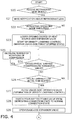
- FIG. 3 is a flowchart of processing that involves switching the operating mode from the normal operating mode to the defrosting operating mode, executing the defrosting operating mode, and returning the operating mode from the defrosting operating mode to the normal operating mode.
- the processing is started in the normal operating mode.
- step S10 the controller 70 determines whether the normal operating mode is continuously executed for the predetermined determination time. Specifically, the controller 70 determines whether the predetermined determination time is elapsed after timing (a recorded time) at which the normal operating mode has started after the termination of the last defrosting operating mode. The controller 70 makes a determination as to a lapse of the predetermined determination time, using the timer control unit 76. When the controller 70 determines that the predetermined determination time is elapsed, the processing proceeds to step S11. When the controller 70 determines that the predetermined determination time is not elapsed, then the controller 70 makes a determination in step S10 again.
- step S11 the controller 70 closes the heat source-side expansion valve 28 with the compressor 21 driven.
- the controller 70 thus suppresses the inflow of the liquid refrigerant into the compressor 21 in large amount in switching the operating mode from the normal operating mode to the defrosting operating mode (i.e., in switching the connection state of the four-way switching valve 22 from the defrosting connection state to the normal connection stat) in step S12 to be described later.
- the processing then proceeds to step S12.
- step S12 the controller 70 switches the operating mode from the normal operating mode to the defrosting operating mode, using the mode control unit 73.
- the defrosting operating mode is executed with the connection state of the four-way switching valve 22 switched to the defrosting connection state.
- the defrosting operation (the refrigeration cycle operation) is performed, causing the refrigerant in the refrigerant circuit 10 to mainly circulate through the compressor 21, the usage-side heat exchanger 52, the usage-side expansion valve 54, the heat source-side expansion valve 28, the receiver 24, and the heat source-side heat exchanger 23 in this order.
- the compressor 21 When the defrosting operation is started, the refrigerant is sucked into and compressed by the compressor 21, and then is discharged from the compressor 21 in the refrigerant circuit 10.
- the compressor 21 is operated at a predetermined maximum driving frequency.
- the gas refrigerant discharged from the compressor 21 flows into the usage-side heat exchanger 52 through the gas-side end of the usage-side heat exchanger 52, via the discharge-side refrigerant pipe 32, the four-way switching valve 22, the second heat source-side gas refrigerant pipe 35, and the gas-refrigerant connection pipe 7.
- the gas refrigerant flows into the usage-side heat exchanger 52 through the gas-side end of the usage-side heat exchanger 52, then the gas refrigerant radiates heat by melting frost on an outer surface of the usage-side heat exchanger 52, so that the gas refrigerant is turned into the liquid refrigerant by condensation. Then, the resultant liquid refrigerant flows out of the usage-side heat exchanger 52 through the liquid-side end of the usage-side heat exchanger 52. The usage-side fan 53 is brought into the stopped state in the defrosting operating mode.
- the liquid refrigerant flows out of the usage-side heat exchanger 52 through the liquid-side end of the usage-side heat exchanger 52, then the liquid refrigerant passes, without being decompressed, through the usage-side expansion valve 54 whose valve opening degree is controlled such that the usage-side expansion valve 54 is in the fully open state.
- the liquid refrigerant then flows into the heat source unit 2 via the liquid-refrigerant connection pipe 6.
- the liquid refrigerant flows into the heat source unit 2, then the liquid refrigerant flows to the heat source-side expansion valve 28.
- the heat source-side expansion valve 28 is controlled by the controller 70 such that the degree of superheating of the refrigerant at the suction side of the compressor 21 becomes a predetermined degree of superheating (e.g., 5 degrees).
- a predetermined degree of superheating e.g., 5 degrees.
- the refrigerant is decompressed to have the low pressure in the refrigerant circuit 10.
- the refrigerant passes through the heat source-side expansion valve 28, then the refrigerant is not shunted to the injection pipe 26 since the injection valve 27 is brought into the fully closed state in the defrosting operating mode.
- the refrigerant then passes through the subcooler 25 where heat exchange is not particularly performed, and flows to the receiver 24.
- the receiver 24 temporarily stores therein the liquid refrigerant in the saturated state. Thereafter, the liquid refrigerant flows out of the receiver 24 through the outlet of the receiver 24.
- the liquid refrigerant flows out of the receiver 24 through the outlet of the receiver 24, then the liquid refrigerant flows into the heat source-side heat exchanger 23 through the liquid-side end of the heat source-side heat exchanger 23.
- the heat source-side heat exchanger 23 causes the refrigerant to exchange heat with the heat source-side air supplied by the heat source-side fan 36 whose airflow volume is controlled to acquire a predetermined maximum number of rotations, thereby evaporating the refrigerant to turn the refrigerant into the gas refrigerant.
- the resultant gas refrigerant then flows out of the heat source-side heat exchanger 23 through the gas-side end of the heat source-side heat exchanger 23.
- the gas refrigerant flows out of the heat source-side heat exchanger 23 through the gas-side end of the heat source-side heat exchanger 23, then the gas refrigerant is sucked into the compressor 21 again via the first heat source-side gas refrigerant pipe 33, the four-way switching valve 22, and the suction-side refrigerant pipe 31.
- step S13 is performed under the execution of the defrosting operating mode described above.
- step S13 the controller 70 determines whether a temperature detected by the usage-side liquid pipe temperature sensor 85 exceeds a predetermined termination determination temperature. When the detected temperature exceeds the termination determination temperature, the processing proceeds to step S14. When the detected temperature does not exceed the termination determination temperature, the controller 70 makes a determination in step S13 again to continue the defrosting operating mode.
- step S14 the controller 70 closes the usage-side expansion valve 54 with the compressor 21 driven.
- the controller 70 thus suppresses the inflow of the liquid refrigerant into the compressor 21 in large amount in switching the operating mode from the defrosting operating mode to the normal operating mode (i.e., in switching the connection state of the four-way switching valve 22 from the normal connection state to the defrosting connection state) in step S15 to be described later.
- the processing then proceeds to step S15.
- step S15 the controller 70 switches the operating mode from the defrosting operating mode to the normal operating mode, using the mode control unit 73. The processing then proceeds to step S16.
- step S16 the controller 70 records a time at which the normal operating mode is resumed. The processing then returns to step S10 and is performed again.
- step S20 the controller 70 determines whether to receive a refrigerant leak signal from the refrigerant leak sensor 81, that is, determines whether to satisfy a predetermined leak condition.
- the processing proceeds to step S21.
- the controller 70 does not receive the refrigerant leak signal, the controller 70 continues the operating mode currently executed, and makes a determination in step S20 again.
- step S21 the controller 70 causes the remote controller 50a to make a notification about occurrence of a refrigerant leak.
- the remote controller 50a may make a notification in the form of display on a screen and in the form of output by sound. The processing then proceeds to step S22.
- step S22 the controller 70 determines whether the operating mode currently executed is the defrosting operating mode. When the defrosting operating mode is currently executed, the processing proceeds to step S23. When the normal operating mode is currently executed, the processing proceeds to step S30 (see FIG. 5 ).
- step S23 the controller 70 switches the operating mode from the defrosting operating mode to the refrigerant leak control mode, and starts the density lowering control. Specifically, the controller 70 lowers the valve opening degree of the heat source-side expansion valve 28 while maintaining the number of rotations of the compressor 21 at the number of rotations in the preceding defrosting operating mode. In the defrosting operating mode, the valve opening degree of the heat source-side expansion valve 28 is controlled such that the suction refrigerant into the compressor 21 has the predetermined degree of superheating. In contrast to this, in the density lowering control, the controller 70 further lowers the valve opening degree below the valve opening degree in the defrosting operating mode.
- the controller 70 lowers the valve opening degree of the heat source-side expansion valve 28 such that the temperature of the refrigerant discharged from the compressor 21 takes a discharge temperature target value higher by a predetermined temperature than the discharge refrigerant temperature in the defrosting operating mode immediately before the start of the refrigerant leak control mode.
- the controller 70 controls the valve opening degree of the heat source-side expansion valve 28 to maintain a state in which the valve opening degree is below the valve opening degree of the heat source-side expansion valve 28 in the defrosting operating mode immediately before the start of the refrigerant leak control mode.
- the controller 70 maintains the usage-side fan 53 at the stopped state continuously from the defrosting operating mode. The processing then proceeds to step S24.
- step S24 the controller 70 determines whether the high-pressure refrigerant in the refrigerant circuit 10 (i.e., the refrigerant pressure detected by the discharge pressure sensor 37c) exceeds a predetermined high-pressure threshold value.
- the processing proceeds to step S25.
- the processing proceeds to step S26.
- step S25 the controller 70 decreases the number of rotations of the compressor 21.
- the controller 70 may decrease the number of rotations of the compressor 21 by, but not limited thereto, a predetermined number of rotations. The processing then returns to step S24.
- step S26 the controller 70 determines whether a predetermined leak initial time set in advance elapses from the start of the density lowering control in step S23, using the timer control unit 76. When the predetermined leak initial time elapses, the processing proceeds to step S27. When the predetermined leak initial time does not elapse, the processing returns to step S24.
- step S27 the controller 70 terminates the density lowering control, and closes the usage-side expansion valve 54 of the usage unit 50 with the compressor 21 driven.
- the controller 70 thus suppresses the inflow of the liquid refrigerant into the compressor 21 in large amount in switching the connection state of the four-way switching valve 22 from the defrosting connection state to the normal connection stat in step S28 to be described later.
- the processing then proceeds to step S28.
- the control for the valve opening degree of the heat source-side expansion valve 28 after the termination of the density lowering control is not limited. In this embodiment, for example, the controller 70 maintains the valve opening degree of the heat source-side expansion valve 28 at the valve opening degree at the termination of the density lowering control.
- step S28 the controller 70 switches the connection state of the four-way switching valve 22 from the defrosting connection state to the normal connection state with the compressor 21 driven. The processing then proceeds to step S29.
- step S29 the controller 70 opens the usage-side expansion valve 54 with the compressor 21 driven.
- the controller 70 may control the valve opening degree of the usage-side expansion valve 54 such that the degree of superheating of the refrigerant to be sucked into the compressor 21 becomes the predetermined degree of superheating.
- the control by the controller 70 is not limited thereto.
- the processing then proceeds to step S30 (see FIG. 5 ).
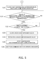
- step S30 the controller 70 closes the heat source-side expansion valve 28 with the compressor 21 driven.
- the controller 70 thus starts the pump down operation for collecting the refrigerant in the refrigerant circuit 10 onto the upstream side of the heat source-side expansion valve 28 and into the heat source-side heat exchanger 23.
- the usage-side fan 53 is brought into a driven state.
- step S31 the controller 70 determines whether a temperature detected by the usage-side liquid pipe temperature sensor 85 is lower than a predetermined temperature.
- the predetermined temperature is not limited and may be set in advance as a temperature to be used for determining that the remaining amount of the refrigerant in the usage-side heat exchanger 52 functioning as the evaporator in the refrigerant circuit 10 is small. This determination enables grasp of a situation in which most of the refrigerant in the refrigerant circuit 10 is collected onto the upstream side of the heat source-side expansion valve 28 and into the heat source-side heat exchanger 23, so that the pump down operation nears the terminatable stage.
- the controller 70 determines that the temperature is lower than the predetermined temperature
- the processing proceeds to step S32.
- the controller 70 determines that the temperature is equal to or higher than the predetermined temperature, the controller 70 makes a determination in step S31 again.
- step S32 the controller 70 determines whether a predetermined standby time elapses from the closure of the heat source-side expansion valve 28 in step S30, using the timer control unit 76. When the predetermined standby time elapses, the processing proceeds to step S33. When the predetermined standby time does not elapse, the controller 70 makes a determination in step S32 again. By a lapse of the predetermined standby time, the refrigerant downstream of the closed heat source-side expansion valve 28 and upstream of the usage-side expansion valve 54 is also collected onto the upstream side of the heat source-side expansion valve 28 and into the heat source-side heat exchanger 23.
- step S33 the controller 70 closes the usage-side expansion valve 54. Closing the usage-side expansion valve 54 enables a reduction in amount of the refrigerant remaining on the upstream side of the usage-side expansion valve 54. Therefore the amount of the refrigerant that leaks from a slight gap of the closed usage-side expansion valve 54 and flows toward a leak spot is reduced even after the operation stop. The processing then proceeds to step S34.
- step S34 the controller 70 performs retightening of the usage-side expansion valve 54. Since the controller 70 closes the usage-side expansion valve 54 in step S33, the usage-side expansion valve 54 should be in the fully closed state. However, the valve may be sometimes in a slightly opened state as unintended since the valve body may not be completely returned to an intended position. For this reason, the controller 70 performs retightening of the usage-side expansion valve 54 by further sending a pulse signal for closing the valve the usage-side expansion valve 54 to further lower the opening degree or completely close the usage-side expansion valve 54.
- step S35 the controller 70 stops the compressor 21 to terminate the pump down operation. The processing then proceeds to step S36.
- step S36 the controller 70 is in a standby state until, for example, a service engineer who receives the notification about the refrigerant leak in step S21 rushes to the site.
- the service engineer inputs a new command through the remote controller 50a on the site, the controller 70 performs processing on the basis of this command.
- the refrigeration apparatus 100 performs the density lowering control to lower the density of the refrigerant supplied to the usage-side heat exchanger 52 when a refrigerant leak occurs at the usage unit 50 in the defrosting operating mode.
- the refrigeration apparatus 100 lowers the valve opening degree of the heat source-side expansion valve 28 such that the temperature of the refrigerant discharged from the compressor 21 takes the discharge temperature target value higher by the predetermined temperature than the discharge refrigerant temperature immediately before the start of the refrigerant leak control mode.
- the refrigeration apparatus 100 lowers the valve opening degree of the heat source-side expansion valve 28 as described above, thereby reducing the pressure of the low-pressure refrigerant on the suction side of the compressor 21 and increasing the degree of superheating of the refrigerant to be sucked into the compressor 21.
- an isentropic change of the refrigerant causes an increase in temperature of the discharge refrigerant and also causes an increase in degree of superheating of the discharge refrigerant.
- the refrigeration apparatus 100 performs the density lowering control to lower the valve opening degree of the heat source-side expansion valve 28, thereby lowering the density of the refrigerant supplied from the compressor 21 toward the usage-side heat exchanger 52 where a refrigerant leak occurs.
- the refrigeration apparatus 100 maintains the rotation of the usage-side fan 53 at the stopped state continuously from the defrosting operation.
- the refrigeration apparatus 100 therefore suppresses an increase in refrigerant density due to condensation of the refrigerant in the usage-side heat exchanger 52, and also suppresses a leak of the high-density refrigerant.
- the refrigeration apparatus 100 decreases the number of rotations of the compressor 21 when the high pressure in the refrigerant circuit 10 exceeds the predetermined high-pressure threshold value after the start of the density lowering control with the heat source-side expansion valve 28 closed.
- the refrigeration apparatus 100 therefore avoids a state in which the refrigerant discharged from the compressor 21 forcibly flows into the leak spot at the usage-side heat exchanger 52, and suppresses an increase in leakage of the refrigerant.
- the refrigeration apparatus 100 suppresses a leak of a high-density refrigerant from a refrigerant leak spot, and reduces the amount of the leakage of the refrigerant.
- the refrigeration apparatus 100 suppresses the leakage of the combustible refrigerant leak, thereby suppressing a state in which the concentration of the leaking refrigerant reaches a combustible range.
- the refrigeration apparatus 100 when a refrigerant leak occurs at the usage unit 50 in the defrosting operating mode, the refrigeration apparatus 100 performs the density lowering control. The refrigeration apparatus 100 then terminates the defrosting operating mode, and switches the connection state of the four-way switching valve 22 from the defrosting connection state to the normal connection state.
- the refrigeration apparatus 100 thus disconnects the discharge side of the compressor 21 from the usage-side heat exchanger 52 corresponding to the leak spot and the vicinity of the usage-side heat exchanger 52, and connects the usage-side heat exchanger 52 corresponding to the leak spot and the vicinity of the usage-side heat exchanger 52 to the suction side of the compressor 21.
- the refrigeration apparatus 100 consequently reduces the amount of the leakage of the refrigerant from the leak spot.
- the refrigeration apparatus 100 when a refrigerant leak occurs, the refrigeration apparatus 100 starts the density lowering control more promptly without being on standby until a condition for terminating the defrosting operating mode, that is, a condition that a temperature detected by the usage-side liquid pipe temperature sensor 85 exceeds the termination determination temperature is satisfied, even in the defrosting operating mode.
- the refrigeration apparatus 100 then switches the connection state of the four-way switching valve 22 from the defrosting connection state to the normal connection state.
- the refrigeration apparatus 100 consequently reduces a time during which a refrigerant leaks in large amount.
- the refrigeration apparatus 100 when a refrigerant leak occurs, the refrigeration apparatus 100 performs the density lowering control, and also performs the pump down operation of collecting the refrigerant in the refrigerant circuit 10 onto the upstream side of the heat source-side expansion valve 28 and into the heat source-side heat exchanger 23. The refrigeration apparatus 100 then stops the compressor 21. The refrigeration apparatus 100 consequently decreases a possibility that the refrigerant reaches the refrigerant leak spot after the stop of the compressor 21.
- the refrigeration apparatus 100 operates the compressor 21 for at least the predetermined standby time with the heat source-side expansion valve 28 closed, and then closes the usage-side expansion valve 54.
- the refrigeration apparatus 100 consequently collects the refrigerant downstream of the closed heat source-side expansion valve 28 and upstream of the usage-side expansion valve 54, onto the upstream side of the heat source-side expansion valve 28 and into the heat source-side heat exchanger 23. Accordingly, since the remaining amount of the refrigerant downstream of the heat source-side expansion valve 28 and upstream of the usage-side expansion valve 54 is small after the stop of the compressor 21, the refrigeration apparatus 100 reduces the amount of the leakage of the refrigerant even if the refrigerant passes through the usage-side expansion valve 54 toward the leak spot.
- the refrigeration apparatus 100 when a refrigerant leak occurs, the refrigeration apparatus 100 performs retightening of the usage-side expansion valve 54, the retightening being not performed in switching the operating mode from the defrosting operating mode to the normal operating mode.
- the refrigeration apparatus 100 consequently reduces, with reliability, the amount of the refrigerant passing through the usage-side expansion valve 54 toward the leak spot.
- the usage-side fan 53 is brought into the stopped state in the defrosting operation. Moreover, even when the density lowering control is performed with the predetermined leak condition satisfied, the usage-side fan 53 is continuously maintained at the stopped state.
- the usage-side fan 53 may not be brought into the stopped state, but may be driven at low speed in the defrosting operation.
- the airflow volume of the usage-side fan 53 may be controlled to be smaller than the airflow volume in the defrosting operation.
- This configuration also suppresses condensation of the refrigerant in the usage-side heat exchanger 52, and suppresses an increase in density of the refrigerant near the leak spot.
- the controller 70 performs the density lowering control due to occurrence of a refrigerant leak, performs the pump down operation with the connection state of the four-way switching valve 22 switched from the defrosting connection state to the normal connection state, and then stops the compressor 21.
- the controller 70 may perform the density lowering control due to occurrence of a refrigerant leak, and then stop the compressor 21 without switching the connection state of the four-way switching valve 22.
- the usage unit 50 of the refrigeration apparatus 100 includes the usage-side expansion valve 54 being an electric expansion valve whose opening degree is controllable.
- a refrigeration apparatus 100a may include: an on-off valve 155 and a thermostatic (mechanical) usage-side expansion valve 154 provided in place of the usage-side expansion valve 54 being an electric expansion valve; and a check circuit 156 and a check valve 157 connecting an upstream side of each of the on-off valve 155 and the usage-side expansion valve 154 to a downstream side of each of the on-off valve 155 and the usage-side expansion valve 154.
- the on-off valve 155 is an electromagnetic valve that is electrically connected to a controller 70, and the controller 70 opens and closes the on-off valve 155.
- the thermostatic (mechanical) usage-side expansion valve 154 is disposed on the side of the usage-side heat exchanger 52 with respect to the on-off valve 155.
- the opening degree of the thermostatic (mechanical) usage-side expansion valve 154 is not controlled by the controller 70, but is automatically changed in accordance with a temperature grasped by a feeler bulb.
- the check circuit 156 connects a portion between the usage-side expansion valve 154 and the usage-side heat exchanger 52 to a portion opposite to the usage-side heat exchanger 52 with respect to the on-off valve 155, on a usage-side liquid refrigerant pipe 59.
- the check circuit 156 branches off the usage-side liquid refrigerant pipe 59 to allow a flow of a refrigerant.
- the check circuit 156 is provided with the check valve 157 that allows a flow of the refrigerant passing through the usage-side heat exchanger 52 toward a liquid-refrigerant connection pipe 6, and interrupts a flow of the refrigerant flowing from the liquid-refrigerant connection pipe 6 toward the usage-side heat exchanger 52.
- the refrigerant flows through the liquid-refrigerant connection pipe 6 and then passes through the on-off valve 155 that is opened.
- the refrigerant is decompressed in the thermostatic (mechanical) usage-side expansion valve 154, and then is supplied to the usage-side heat exchanger 52 functioning as an evaporator.
- the refrigerant passes through the usage-side heat exchanger 52 functioning as a radiator, and then flows toward the liquid-refrigerant connection pipe 6 via the check circuit 156 and the check valve 157.
- the controller 70 closes the on-off valve 155 instead of the usage-side expansion valve 54 in the foregoing embodiment.
- the controller 70 in starting the density lowering control in the refrigerant leak control mode, the controller 70 lowers the valve opening degree of the heat source-side expansion valve 28 while maintaining the number of rotations of the compressor 21 in the preceding defrosting operating mode, thereby lowering the density of the refrigerant supplied to the usage unit 50.
- the method of lowering the density of the refrigerant supplied to the usage unit 50 is not limited to the method described in the foregoing embodiment.
- the controller 70 may control the number of rotations of the compressor 21 and the valve opening degree of the heat source-side expansion valve 28 in combination so as to lower the refrigerant density.
- the storage unit 71 of the controller 70 previously may store therein an information table showing the relationship between the preset number of rotations of the compressor 21 and the corresponding valve opening degree of the heat source-side expansion valve 28. Then, the controller 70 may perform the density lowering control to control the number of rotations of the compressor 21 and the valve opening degree of the heat source-side expansion valve 28, on the basis of the information table.
- the refrigeration apparatus 100 is of a pair type in which the heat source unit 2 and the usage unit 50 are connected in one to one correspondence.
- the number of usage units and the number of heat source units are not limited to one.
- the refrigeration apparatus 100 may include a plurality of usage units and a plurality of heat source units.
- the refrigeration apparatus 100 may include one heat source unit and a plurality of usage units connected to the heat source unit in parallel.
- the refrigerant leak sensor 81 is disposed to detect a refrigerant leak at the usage unit 50. If a refrigerant leak at the usage unit 50 is detectable without the refrigerant leak sensor 81, however, the refrigeration apparatus 100 does not necessarily include the refrigerant leak sensor 81.
- the usage unit 50 may include a sensor such as a refrigerant pressure sensor or a refrigerant temperature sensor. If a refrigerant leak at the usage unit 50 is detectable on the basis of a change of a value detected by such a sensor, the refrigerant leak sensor 81 may be omitted.
- a sensor such as a refrigerant pressure sensor or a refrigerant temperature sensor. If a refrigerant leak at the usage unit 50 is detectable on the basis of a change of a value detected by such a sensor, the refrigerant leak sensor 81 may be omitted.
- the refrigeration apparatus 100 is configured to cool, for example, the interior of a cold storage warehouse or the interior of a showcase in a store.
- the refrigeration apparatus 100 may be configured to cool the interior of a container for transportation.
- the refrigeration apparatus 100 may be an air conditioning system (an air conditioner) that achieves air conditioning by cooling the interior of a building or the like.
- R32 is employed as a refrigerant that circulates through the refrigerant circuit 10.
- the refrigerant for use in the refrigerant circuit 10 is not limited there to.
- HFO1234yf, HFO1234ze, and a mixture thereof may be employed in place of R32 for the refrigerant circuit 10.
- a hydrofluorocarbon (HFC) refrigerant such as R407C or R410A may be employed for the refrigerant circuit 10.
- a combustible refrigerant such as propane or a toxic refrigerant such as ammonia may be employed for the refrigerant circuit 10.
- the present invention is applicable to a refrigeration apparatus.
- Patent Literature 1 JP 2015-94573 A
Landscapes
- Engineering & Computer Science (AREA)
- Physics & Mathematics (AREA)
- Mechanical Engineering (AREA)
- Thermal Sciences (AREA)
- General Engineering & Computer Science (AREA)
- Chemical & Material Sciences (AREA)
- Combustion & Propulsion (AREA)
- Air Conditioning Control Device (AREA)
- Defrosting Systems (AREA)
Abstract
Description
- The present invention relates to a refrigeration apparatus.
- In a refrigeration cycle using a refrigerant circuit including a compressor, a heat source-side heat exchanger, an expansion valve, and a usage-side heat exchanger that are interconnected, heretofore, a refrigerant leak has sometimes occurred at the usage-side heat exchanger and its vicinity for any reason.
- In this respect, for example, Patent Literature 1 (
JP 2015-94573 A - If frost forms on the usage-side heat exchanger that functions as an evaporator for the refrigerant, it has been considered to perform a defrosting operation of, in order to melt the frost, switching a connection state of the refrigerant circuit, supplying to the usage-side heat exchanger the high-temperature refrigerant discharged from the compressor, and causing the usage-side heat exchanger to function as a radiator for the refrigerant.
- In the defrosting operation, the refrigerant discharged from the compressor is continuously supplied to the usage-side heat exchanger, and is condensed by heat exchange for defrosting, which results in an increase of the amount of the refrigerant in the usage-side heat exchanger. Accordingly, if the refrigerant leak occurs at the usage-side heat exchanger and its vicinity in the defrosting operation, the leakage of the refrigerant may increase. This may cause an increase in concentration of the refrigerant in the space where the usage-side heat exchanger is placed.
- In view of the aspects described above, the present invention provides a refrigeration apparatus capable of reducing the leakage of a refrigerant even when a refrigerant leak occurs in a defrosting operation of a usage-side heat exchanger.
- According to a first aspect, a refrigeration apparatus includes a refrigerant circuit and a control unit. The refrigerant circuit includes: a compressor, a heat source-side heat exchanger, and a heat source-side expansion valve of a heat source unit; and a usage-side heat exchanger and a switching valve of a usage unit. The switching valve is capable of switching a connection state of the refrigerant circuit between a normal connection state and a defrosting connection state. In the normal connection state, the heat source-side heat exchanger functions as a radiator for a refrigerant, and the usage-side heat exchanger functions as an evaporator for the refrigerant. In the defrosting connection state, the heat source-side heat exchanger functions as an evaporator for the refrigerant, and the usage-side heat exchanger functions as a radiator for the refrigerant. The control unit is configured to switch the connection state of the switching valve to the defrosting connection state and to perform a defrosting operation when a predetermined defrosting condition is satisfied in the normal connection state of the switching valve. The control unit performs density lowering control to lower a refrigerant density in the usage-side heat exchanger while maintaining the switching valve at the defrosting connection state when a refrigerant leak situation around the usage-side heat exchanger satisfies a predetermined leak condition in the defrosting operation.
- Examples of the case where the refrigerant leak situation satisfies the predetermined leak condition may include, but not limited to, a case where a sensor detects that a leakage refrigerant concentration around the usage-side heat exchanger is equal to or more than a predetermined concentration, and a case where a sensor detects a change or reduction in value of a pressure or temperature of a refrigerant flowing through the usage-side heat exchanger or a pipe connected to the usage-side heat exchanger.
- The refrigeration apparatus performs the density lowering control to lower the refrigerant density in the usage-side heat exchanger while maintaining the switching valve at the defrosting connection state when the refrigerant leak situation around the usage-side heat exchanger satisfies the predetermined leak condition in the defrosting operation. The refrigeration apparatus performs the density lowering control without changing the connection state of the switching valve, and therefore reduces the amount of the leakage of the refrigerant with ease.
- According to a second aspect, in the refrigeration apparatus according to the first aspect, when the refrigerant leak situation around the usage-side heat exchanger satisfies the predetermined leak condition in the defrosting operation, the control unit performs the density lowering control by raising a temperature of the refrigerant discharged from the compressor while maintaining the switching valve at the defrosting connection state.
- The refrigeration apparatus puts the state of the refrigerant supplied to the usage-side heat exchanger into the superheated gas state, by raising the temperature of the refrigerant discharged from the compressor. The refrigeration apparatus thus lowers the refrigerant density.
- According to a third aspect, in the refrigeration apparatus according to the second aspect, when the refrigerant leak situation around the usage-side heat exchanger satisfies the predetermined leak condition in the defrosting operation, the control unit raises the temperature of the refrigerant discharged from the compressor, by lowering a valve opening degree of the heat source-side expansion valve below a valve opening degree immediately before the refrigerant leak situation satisfies the predetermined leak condition, while maintaining the switching valve at the defrosting connection state.
- The refrigeration apparatus lowers the density of the refrigerant supplied to the usage-side heat exchanger, by a simple operation of lowering the valve opening degree of the heat source-side expansion valve below the valve opening degree immediately before the refrigerant leak situation satisfies the predetermined leak condition.
- According to a fourth aspect, the refrigeration apparatus according to any of the first to third aspects further includes a usage-side fan. The usage-side fan is of the usage unit and is configured to provide an air flow for the usage-side heat exchanger. When the refrigerant leak situation around the usage-side heat exchanger satisfies the predetermined leak condition in the defrosting operation, the control unit maintains or decreases an airflow volume of the usage-side fan at or below an airflow volume immediately before the refrigerant leak situation satisfies the predetermined leak condition, while maintaining the switching valve at the defrosting connection state.
- The refrigeration apparatus maintains or decreases the airflow volume of the usage-side fan, and therefore does not increase the airflow volume of the usage-side fan. Hence, the refrigeration apparatus suppresses accelerated condensation of the refrigerant in the usage-side heat exchanger. The refrigeration apparatus thus lowers the refrigerant density in the usage-side heat exchanger with ease.
- According to a fifth aspect, in the refrigeration apparatus according to any of the first to fourth aspects, when a predetermined termination condition for terminating the density lowering control is satisfied, the control unit switches the connection state of the switching valve to the normal connection state, and then stops the compressor.
- The refrigeration apparatus performs the density lowering control to lower the refrigerant density at the leak spot, and then switches the connection state of the switching valve from the defrosting connection state to the normal connection state when the refrigerant leak situation satisfies the predetermined leak condition. The refrigeration apparatus thus further reduces the amount of the leakage of the refrigerant around the usage-side heat exchanger, by connecting the usage-side heat exchanger, which has been connected to a discharge side of the compressor, to a suction side of the compressor.
- According to a sixth aspect, the refrigeration apparatus according to any of the first to fifth aspects further includes a usage-side temperature sensor. The usage-side temperature sensor is configured to detect a temperature of the refrigerant flowing through the usage-side heat exchanger. The control unit switches the connection state of the switching valve to the normal connection state after the termination of the density lowering control, and then stops the compressor. When the refrigerant leak situation does not satisfy the predetermined leak condition in the defrosting operation, the control unit terminates the defrosting operation when the temperature detected by the usage-side temperature sensor satisfies a predetermined temperature condition, and then switches the connection state of the switching valve to the normal connection state.
- When the refrigerant leak situation does not satisfy the predetermined leak condition, the refrigeration apparatus continues the defrosting operation until the temperature detected by the usage-side temperature sensor satisfies the predetermined temperature condition. This configuration enables more satisfactory melting of frost on the usage-side heat exchanger. When the refrigerant leak situation satisfies the predetermined leak condition, the control unit does not continue the defrosting operation up to a time when the temperature detected by the usage-side temperature sensor satisfies the predetermined temperature condition, but performs the density lowering control even the temperature does not satisfy the predetermined temperature condition. The refrigeration apparatus therefore performs satisfactory defrosting when the refrigerant leak situation does not satisfy the predetermined leak condition, and promptly switches to a state in which a refrigerant leak hardly occurs when the refrigerant leak situation satisfies the predetermined leak condition.
- According to a seventh aspect, the refrigeration apparatus according to the sixth aspect further includes a usage-side expansion valve. The usage-side expansion valve is of the usage unit and is disposed in a liquid side of the usage-side heat exchanger. When the refrigerant leak situation satisfies the predetermined leak condition in the defrosting operation, the control unit performs retightening of the usage-side expansion valve. When the refrigerant leak situation does not satisfy the predetermined leak condition in the defrosting operation, the control unit does not perform retightening of the usage-side expansion valve.
- In a typical expansion valve whose valve opening degree is adjustable, the valve may not be completely closed even in a fully closed state, and may be slightly opened as unintended in some instances. If the valve is slightly opened as unintended, a refrigerant leak is likely to last as unintended although almost no adverse effects are exerted in a normal operation.
- In view of this, the refrigeration apparatus performs retightening of the usage-side expansion valve when the refrigerant leak situation satisfies the predetermined leak condition. The refrigeration apparatus therefore suppresses a state in which the refrigerant is continuously supplied to the usage-side heat exchanger via the usage-side expansion valve, even in a case where the control unit performs the density lowering control when the refrigerant leak situation satisfies the predetermined leak condition in the defrosting operation, and then switches the connection state of the switching valve to the normal connection state and drives the compressor until a time to stop the compressor comes.
- The refrigeration apparatus according to the first aspect reduces the amount of the leakage of a refrigerant even when a refrigerant leak occurs in a defrosting operation of the usage-side heat exchanger.
- The refrigeration apparatus according to the second aspect lowers a refrigerant density by putting the state of the refrigerant supplied to the usage-side heat exchanger into the superheated gas state.
- The refrigeration apparatus according to the third aspect lowers the density of the refrigerant supplied to the usage-side heat exchanger, with a simple operation.
- The refrigeration apparatus according to the fourth aspect easily lowers the refrigerant density in the usage-side heat exchanger.
- The refrigeration apparatus according to the fifth aspect lowers a refrigerant density at a leak spot, and further reduces the amount of the leakage of the refrigerant by connecting the usage-side heat exchanger to the suction side of the compressor.
- The refrigeration apparatus according to the sixth aspect performs satisfactory defrosting when the refrigerant leak situation does not satisfy the predetermined leak condition, and promptly switches to a state in which a refrigerant leak hardly occurs when the refrigerant leak situation satisfies the predetermined leak condition.
- The refrigeration apparatus according to the seventh aspect suppresses a state in which the refrigerant is continuously supplied to the usage-side heat exchanger via the usage-side expansion valve, even in a case where the control unit performs the density lowering control, and then switches the connection state of the switching valve to the normal connection state and drives the compressor until a time to stop the compressor comes.
-
-
FIG. 1 is a general configuration diagram of a refrigeration apparatus according to an embodiment of the present invention. -
FIG. 2 is a schematic block diagram of a schematic configuration of a controller and components connected to the controller. -
FIG. 3 is a flowchart of exemplary processing to be performed by the controller in a defrosting operating mode. -
FIG. 4 is a flowchart (first half) of exemplary processing to be performed by the controller in a refrigerant leak control mode. -
FIG. 5 is a flowchart (second half) of exemplary processing to be performed by the controller in the refrigerant leak control mode. -
FIG. 6 is a general configuration diagram of a refrigeration apparatus including a refrigerant circuit according to Modification C. - A
refrigeration apparatus 100 according to an embodiment of the present invention will be described below with reference to the drawings. It should be noted that the following embodiments are merely specific examples of the present invention, do not intend to limit the technical scope of the present invention, and may be appropriately modified without departing from the gist of the present invention. -
FIG. 1 is a schematic configuration diagram of arefrigeration apparatus 100 according to an embodiment of the present invention. Therefrigeration apparatus 100 employs a vapor compression refrigeration cycle to cool a usage-side space such as the interior of a cold storage warehouse or the interior of a showcase in a store. - The
refrigeration apparatus 100 mainly includes: aheat source unit 2; ausage unit 50; a liquid-refrigerant connection pipe 6 and a gas-refrigerant connection pipe 7 each connecting theheat source unit 2 to theusage unit 50; arefrigerant leak sensor 81 configured to detect a refrigerant leak in theusage unit 50; aremote controller 50a serving as an input device and a display device; and acontroller 70 configured to control operation of therefrigeration apparatus 100. - The
refrigeration apparatus 100 performs a refrigeration cycle to compress, cool or condense, decompress, heat or evaporate, and then compress again a sealed-in refrigerant in arefrigerant circuit 10. In this embodiment, therefrigerant circuit 10 is filled with R32 as a refrigerant for a vapor compression refrigeration cycle. - The
heat source unit 2 is connected to theusage unit 50 via the liquid-refrigerant connection pipe 6 and the gas-refrigerant connection pipe 7, and constitutes a part of therefrigerant circuit 10. Theheat source unit 2 mainly includes acompressor 21, a four-way switching valve 22, a heat source-side heat exchanger 23, a heat source-side fan 36, areceiver 24, asubcooler 25, a heat source-side expansion valve 28, aninjection pipe 26, aninjection valve 27, a liquid-side shutoff valve 29, and a gas-side shutoff valve 30. - The
heat source unit 2 also includes: a suction-side refrigerant pipe 31 connecting a suction side of thecompressor 21 to a first connection port of the four-way switching valve 22; a discharge-side refrigerant pipe 32 connecting a discharge side of thecompressor 21 to a third connection port of the four-way switching valve 22; a first heat source-sidegas refrigerant pipe 33 connecting a second connection port of the four-way switching valve 22 to a gas-side end of the heat source-side heat exchanger 23; a heat source-side liquidrefrigerant pipe 34 connecting a liquid-side end of the heat source-side heat exchanger 23 to the liquid-refrigerant connection pipe 6; and a second heat source-sidegas refrigerant pipe 35 connecting the gas-refrigerant connection pipe 7 to a fourth connection port of the four-way switching valve 22. - The
heat source unit 2 includes: theinjection pipe 26 configured to shunt part of the refrigerant flowing through the heat source-side liquidrefrigerant pipe 34 back to thecompressor 21; and theinjection valve 27 disposed at the middle of theinjection pipe 26. Theinjection pipe 26 branches off the heat source-side liquidrefrigerant pipe 34 at a portion downstream of thesubcooler 25, passes through thesubcooler 25, and is connected to thecompressor 21 in an intermediate state of a compression process. - The
compressor 21 is a device configured to change by compression a low-pressure refrigerant to a high-pressure refrigerant in the refrigeration cycle. Thecompressor 21 used herein is a closed compressor in which a displacement compression element, such as rotary or scroll, (not illustrated) is driven to rotate by a compressor motor M21. Although not illustrated in the drawings, thecompressor 21 in this embodiment includes one or more constant-speed compressors and a variable displacement compressor that are connected in parallel. The variable displacement compressor includes the compressor motor M21 and has an operating frequency controllable by an inverter. In decreasing the capacity of thecompressor 21, the operating frequency of the variable displacement compressor is lowered. In further decreasing the capacity of the variable displacement compressor even though the operating frequency of the variable displacement compressor has been lowered, the constant-speed compressors are stopped. However, the method of decreasing the capacity is not limited thereto. - The four-
way switching valve 22 is configured to switch a connection state of therefrigerant circuit 10 between a normal connection state and a defrosting connection state. In the normal connection state, the four-way switching valve 22 connects the second connection port to the third connection port and also connects the first connection port to the fourth connection port (see a solid line inFIG. 1 ), thereby bringing therefrigerant circuit 10 into a state in which the heat source-side heat exchanger 23 is connected to the discharge side of thecompressor 21 and the gas-refrigerant connection pipe 7 is connected to the suction side of thecompressor 21 via the suction-side refrigerant pipe 31 and the second heat source-sidegas refrigerant pipe 35. In the defrosting connection state, the four-way switching valve 22 connects the first connection port to the second connection port and also connects the third connection port to the fourth connection port (see a dotted line inFIG. 1 ), thereby bringing therefrigerant circuit 10 into a state in which the gas-refrigerant connection pipe 7 is connected to the discharge side of thecompressor 21 via the second heat source-sidegas refrigerant pipe 35 and the heat source-side heat exchanger 23 is connected to the suction side of thecompressor 21 via the suction-side refrigerant pipe 31. When the four-way switching valve 22 is in the normal connection state, a cooling operation is performed, in which the heat source-side heat exchanger 23 functions as a radiator for the refrigerant and a usage-side heat exchanger 52 functions as an evaporator for the refrigerant. When the four-way switching valve 22 is in the defrosting connection state, a defrosting operation is performed, in which the usage-side heat exchanger 52 functions as a radiator for the refrigerant and the heat source-side heat exchanger 23 functions as an evaporator for the refrigerant. - The heat source-
side heat exchanger 23 functions as the radiator for the refrigerant in the cooling operation, and also functions as the evaporator for the refrigerant in the defrosting operation. Theheat source unit 2 includes the heat source-side fan 36 for sucking outside air (heat source-side air) into theheat source unit 2, causing the heat source-side air to exchange heat with the refrigerant in the heat source-side heat exchanger 23, and then discharging the heat source-side air. The heat source-side fan 36 is configured to supply to the heat source-side heat exchanger 23 the heat source-side air for cooling the refrigerant flowing through the heat source-side heat exchanger 23. The heat source-side fan 36 is driven to rotate by a heat source-side fan motor M36. - The
receiver 24 temporarily stores therein a surplus refrigerant in therefrigerant circuit 10. Thereceiver 24 is disposed at the middle of the heat source-side liquidrefrigerant pipe 34. - The
subcooler 25 is a heat exchanger for further cooling the refrigerant temporarily stored in thereceiver 24 in the cooling operation. Thesubcooler 25 is disposed in the heat source-side liquidrefrigerant pipe 34. Specifically, thesubcooler 25 is disposed closer to the liquid-refrigerant connection pipe 6 than thereceiver 24 is. - The heat source-
side expansion valve 28 is an electric expansion valve whose opening degree is controllable. The heat source-side expansion valve 28 is disposed in the heat source-side liquidrefrigerant pipe 34. Specifically, the heat source-side expansion valve 28 is disposed closer to the liquid-refrigerant connection pipe 6 than thesubcooler 25 is. - The
injection valve 27 is disposed in theinjection pipe 26. Specifically, theinjection valve 27 is disposed between a branched portion of the heat source-side liquidrefrigerant pipe 34 and an inlet of thesubcooler 25. Theinjection valve 27 is an electric expansion valve whose opening degree is controllable. Theinjection valve 27 decompresses, in accordance with its opening degree, the refrigerant flowing through theinjection pipe 26 before the refrigerant flows into thesubcooler 25. - The liquid-
side shutoff valve 29 is a manual valve disposed at a joint between the heat source-side liquidrefrigerant pipe 34 and the liquid-refrigerant connection pipe 6. - The gas-
side shutoff valve 30 is a manual valve disposed at a joint between the second heat source-sidegas refrigerant pipe 35 and the gas-refrigerant connection pipe 7. - The
heat source unit 2 includes various sensors. In theheat source unit 2, specifically, asuction pressure sensor 37a, asuction temperature sensor 37b, adischarge pressure sensor 37c, and adischarge temperature sensor 37d are disposed around thecompressor 21. Thesuction pressure sensor 37a is configured to detect a suction pressure that is a pressure of the refrigerant at the suction side of thecompressor 21. Thesuction temperature sensor 37b is configured to detect a suction temperature that is a temperature of the refrigerant at the suction side of thecompressor 21. Thedischarge pressure sensor 37c is configured to detect a discharge pressure that is a pressure of the refrigerant at the discharge side of thecompressor 21. Thedischarge temperature sensor 37d is configured to detect a discharge temperature that is a temperature of the refrigerant at the discharge side of thecompressor 21. On the heat source-side liquidrefrigerant pipe 34, a receiveroutlet temperature sensor 38 is disposed between an outlet of thereceiver 24 and the inlet of thesubcooler 25. The receiveroutlet temperature sensor 38 is configured to detect a receiver outlet temperature that is a temperature of the refrigerant at the outlet of thereceiver 24. Moreover, a heat source-sideair temperature sensor 39 is disposed around the heat source-side heat exchanger 23 or the heat source-side fan 36. The heat source-sideair temperature sensor 39 is configured to detect a temperature of heat source-side air to be sucked into theheat source unit 2. - The
heat source unit 2 also includes a heat sourceunit control unit 20 configured to control operations of the respective components constituting theheat source unit 2. The heat sourceunit control unit 20 includes a microcomputer including, for example, a central processing unit (CPU) and a memory. The heat sourceunit control unit 20 is connected to a usageunit control unit 57 of theusage unit 50 via a communication line to exchange, for example, a control signal with the usageunit control unit 57. - The
usage unit 50 is connected to theheat source unit 2 via the liquid-refrigerant connection pipe 6 and the gas-refrigerant connection pipe 7, and constitutes a part of therefrigerant circuit 10. - The
usage unit 50 includes a usage-side expansion valve 54 and a usage-side heat exchanger 52. Theusage unit 50 also includes: a usage-side liquidrefrigerant pipe 59 connecting a liquid-side end of the usage-side heat exchanger 52 to the liquid-refrigerant connection pipe 6; and a usage-sidegas refrigerant pipe 58 connecting a gas-side end of the usage-side heat exchanger 52 to the gas-refrigerant connection pipe 7. - The usage-
side expansion valve 54 is a restrictor disposed at the middle of the usage-side liquidrefrigerant pipe 59 and functioning as means for decompressing the refrigerant passing therethrough. In this embodiment, the usage-side expansion valve 54 is an electric expansion valve whose opening degree is controllable. Specifically, the usage-side expansion valve 54 has a valve opening degree changeable under the pulse control by a pulse motor. - The usage-
side heat exchanger 52 functions as an evaporator for the refrigerant to cool inside air (usage-side air) in the cooling operation, and also functions as a radiator for the refrigerant to melt frost on a surface of the usage-side heat exchanger 52 in the defrosting operation. - The
usage unit 50 includes a usage-side fan 53 for sucking usage-side air into theusage unit 50, causing the usage-side air to exchange heat with the refrigerant in the usage-side heat exchanger 52, and then supplying the usage-side air to the usage-side space. The usage-side fan 53 is configured to supply to the usage-side heat exchanger 52 the usage-side air for heating the refrigerant flowing through the usage-side heat exchanger 52 in the cooling operation. The usage-side fan 53 is driven to rotate by a usage-side fan motor M53. The usage-side fan 53 is brought into a stopped state in the defrosting operation. - The
usage unit 50 also includes a usage-side liquidpipe temperature sensor 85 configured to detect a temperature of the refrigerant flowing through a position opposite from the usage-side heat exchanger 52 with respect to the usage-side expansion valve 54 in the middle of the usage-side liquidrefrigerant pipe 59. - The
usage unit 50 also includes the usageunit control unit 57 configured to control operations of the respective components constituting theusage unit 50. Specifically, the usageunit control unit 57 controls the opening degree of the usage-side expansion valve 54, and the airflow volume of the usage-side fan 53. The usageunit control unit 57 includes a microcomputer including, for example, a CPU and a memory. The usageunit control unit 57 is connected to the heat sourceunit control unit 20 via the communication line to exchange, for example, a control signal with the heat sourceunit control unit 20. The usageunit control unit 57 is electrically connected to therefrigerant leak sensor 81 and the usage-side liquidpipe temperature sensor 85, thereby receiving signals from therefrigerant leak sensor 81 and the usage-side liquidpipe temperature sensor 85. - The
refrigerant leak sensor 81 is configured to detect a refrigerant leak in theusage unit 50. Therefrigerant leak sensor 81 is disposed in a casing of theusage unit 50. Therefrigerant leak sensor 81 to be used in this embodiment is a well-known general-purpose product. - Upon detection of a refrigerant leak, the
refrigerant leak sensor 81 outputs an electric signal (hereinafter, referred to as a "refrigerant leak signal") indicative of occurrence of a refrigerant leak, to the usageunit control unit 57 connected thereto. - The
remote controller 50a is an input device that causes a user of theusage unit 50 to input various instructions for switching an operating state of therefrigeration apparatus 100. Theremote controller 50a also functions as a display device for displaying the operating state of therefrigeration apparatus 100 and predetermined notification information. Theremote controller 50a is connected to the usageunit control unit 57 via a communication line to exchange signals with the usageunit control unit 57. - In the
refrigeration apparatus 100, the heat sourceunit control unit 20 and the usageunit control unit 57 are connected via the communication line to constitute thecontroller 70 for controlling operation of therefrigeration apparatus 100. -
FIG. 2 is a schematic block diagram of a schematic configuration of thecontroller 70 and the components connected to thecontroller 70. - The
controller 70 has a plurality of control modes, and controls the operation of therefrigeration apparatus 100 in accordance with a control mode in which thecontroller 70 is stated. Examples of the control modes of thecontroller 70 include: a normal operating mode in which thecontroller 70 is stated in a normal situation; a defrosting operating mode in which thecontroller 70 is stated in defrosting the usage-side heat exchanger 52; and a refrigerant leak control mode in which thecontroller 70 is stated upon occurrence of a refrigerant leak. - The
controller 70 is electrically connected to the actuators (i.e., the compressor 21 (the compressor motor M21), the heat source-side expansion valve 28, theinjection valve 27, and the heat source-side fan 36 (the heat source-side fan motor M36)) and the various sensors (i.e., thesuction pressure sensor 37a, thesuction temperature sensor 37b, thedischarge pressure sensor 37c, thedischarge temperature sensor 37d, the receiveroutlet temperature sensor 38, the heat source-sideair temperature sensor 39, and the like) in theheat source unit 2. Thecontroller 70 is also electrically connected to the actuators (i.e., the usage-side fan 53 (the usage-side fan motor M53), the usage-side expansion valve 54) in theusage unit 50. Thecontroller 70 is also electrically connected to therefrigerant leak sensor 81 and theremote controller 50a. - The
controller 70 mainly includes astorage unit 71, acommunication unit 72, amode control unit 73, anactuator control unit 74, and adisplay control unit 75. These units in thecontroller 70 are implemented in such a manner that the components in the heat sourceunit control unit 20 and/or the usageunit control unit 57 integrally function. - The
storage unit 71 includes, for example, a read only memory (ROM), a random access memory (RAM), and a flash memory. Thestorage unit 71 has a volatile storage region and a nonvolatile storage region. Thestorage unit 71 stores therein a control program that defines processing to be performed by each unit of thecontroller 70. Also in thestorage unit 71, the respective units of thecontroller 70 appropriately store predetermined information (e.g., values detected by the respective sensors, commands input to theremote controller 50a) in a predetermined storage region. - The
communication unit 72 is a functional unit that plays a role as a communication interface for exchanging signals with the respective components connected to thecontroller 70. Thecommunication unit 72 receives a request from theactuator control unit 74, and transmits a predetermined signal to a designated one of the actuators. Thecommunication unit 72 also receives signals from the various sensors (37a, 37b, 37c, 37d, 38, 39), therefrigerant leak sensor 81, and theremote controller 50a, and stores the received signals in the predetermined storage region of thestorage unit 71. - The
mode control unit 73 is a functional unit that switches a control mode, for example. In a state in which therefrigerant leak sensor 81 detects no refrigerant leak, themode control unit 73 sets the control mode at the normal operating mode or the defrosting operating mode. Themode control unit 73 switches between the normal operating mode and the defrosting operating mode in accordance with a predetermined defrosting condition. - When the
refrigerant leak sensor 81 detects a refrigerant leak, themode control unit 73 sets the control mode at the refrigerant leak control mode. - The
actuator control unit 74 controls, on the basis of the control program, the operations of the respective actuators (e.g., the compressor 21) in therefrigeration apparatus 100, in accordance with a situation. - In the normal operating mode, for example, the
actuator control unit 74 controls the number of rotations of thecompressor 21, the valve opening degree of the usage-side expansion valve 54, the airflow volume of the heat source-side fan 36, the airflow volume of the usage-side fan 53, and the opening degree of theinjection valve 27 in real time, in accordance with, for example, set temperatures and values detected by the various sensors, with the four-way switching valve 22 brought into the normal connection state. In the normal operating mode, theactuator control unit 74 brings the heat source-side expansion valve 28 into the fully open state. In the normal operating mode, theactuator control unit 74 sets a target value of a suction pressure in accordance with a cooling load to be required for theusage unit 50, and controls the operating frequency of thecompressor 21 so as to acquire the suction pressure with the target value. - In the defrosting operating mode, the
actuator control unit 74 controls, for example, the number of rotations of thecompressor 21, the airflow volume of the heat source-side fan 36, and the valve opening degree of the heat source-side expansion valve 28, with the four-way switching valve 22 brought into the defrosting connection state. In the defrosting operating mode, for example, theactuator control unit 74 may control the number of rotations of thecompressor 21 so as to maximize the number of rotations. Alternatively, theactuator control unit 74 may control the number of rotations of thecompressor 21 so as to raise the pressure of the refrigerant discharged from thecompressor 21 to a predetermined high pressure. However, the control by theactuator control unit 74 is not limited thereto. Also in the defrosting operating mode, theactuator control unit 74 may control the airflow volume of the heat source-side fan 36 so as to maximize the airflow volume. In this embodiment, in the defrosting operating mode, theactuator control unit 74 controls the valve opening degree of the heat source-side expansion valve 28 such that the suction refrigerant in thecompressor 21 has a predetermined degree of superheating. In the defrosting operating mode, theactuator control unit 74 controls the usage-side expansion valve 54 so as to bring the usage-side expansion valve 54 into the fully open state, controls the usage-side fan 53 so as to bring the usage-side fan 53 into the stopped state, and controls theinjection valve 27 so as to bring theinjection valve 27 into a fully closed state. - In executing the refrigerant leak control mode on the basis of detection of a refrigerant leak by the
refrigerant leak sensor 81 in the defrosting operating mode, theactuator control unit 74 performs density lowering control to lower the density of the refrigerant be supplied to the usage-side heat exchanger 52, during a predetermined leak initial time. In the density lowering control, theactuator control unit 74 lowers the valve opening degree of the heat source-side expansion valve 28 below the valve opening degree immediately before a start of the refrigerant leak control mode. Specifically, theactuator control unit 74 starts the density lowering control by lowering the valve opening degree of the heat source-side expansion valve 28 such that the temperature of the refrigerant discharged from the compressor 21 (i.e., the refrigerant temperature detected by thedischarge temperature sensor 37d) takes a discharge temperature target value that is higher by a predetermined temperature than a discharge refrigerant temperature immediately before the start of the refrigerant leak control mode. Theactuator control unit 74 controls the valve opening degree of the heat source-side expansion valve 28 such that the temperature of the refrigerant discharged from thecompressor 21 takes the discharge temperature target value. However, theactuator control unit 74 controls the valve opening degree so as to maintain the valve opening degree at a state below the valve opening degree of the heat source-side expansion valve 28 immediately before the start of the refrigerant leak control mode. When the high-pressure refrigerant in the refrigerant circuit 10 (i.e., the refrigerant pressure detected by thedischarge pressure sensor 37c) is more than a predetermined high-pressure threshold value after the start of the density lowering control, theactuator control unit 74 further decreases the number of rotations of thecompressor 21. The target value in decreasing the number of rotations of thecompressor 21 is not limited, and theactuator control unit 74 may decrease the number so as to have a pressure equal to or less than a predetermined reference pressure set in advance. In the density lowering control, preferably, the heat source-side expansion valve 28 is not brought into the fully closed state since the refrigerant from a leak spot at theusage unit 50 can be continuously recovered to theheat source unit 2. - After the density lowering control for the predetermined leak initial time, the
actuator control unit 74 switches the connection state of the four-way switching valve 22 from the defrosting connection state to the normal connection state, and then performs a pump down operation to stop thecompressor 21. - When the
refrigerant leak sensor 81 detects a refrigerant leak in the normal operating mode, theactuator control unit 74 performs the pump down operation to stop thecompressor 21 while maintaining the connection state of the four-way switching valve 22 at the normal connection state. - The
display control unit 75 is a functional unit that controls operation of theremote controller 50a serving as the display device. - The
display control unit 75 causes theremote controller 50a to output predetermined information in order that an operating state or information on a situation is displayed for an administrator. - For example, the
display control unit 75 causes theremote controller 50a to display thereon various kinds of information, such as set temperatures, during the cooling operation and the defrosting operation in the normal operating mode. - In the refrigerant leak control mode, the
display control unit 75 causes theremote controller 50a to display thereon information indicative of occurrence of a refrigerant leak. Also in the refrigerant leak control mode, thedisplay control unit 75 causes theremote controller 50a to display thereon information urging the user to make a notification to a service engineer. - A
timer control unit 76 is a functional unit that measures an elapsed time for predetermined processing, for example. Specifically, the defrosting operation is started when the normal operating mode is continuously executed for a predetermined determination time. In this case, thetimer control unit 76 measures the predetermined determination time, for example. In addition, the density lowering control is performed for the predetermined leak initial time in executing the refrigerant leak control mode on the basis of the detection of the refrigerant leak by therefrigerant leak sensor 81 in the defrosting operating mode. In this case, thetimer control unit 76 also measures the predetermined leak initial time. - Next, a description will be given of the flow of the refrigerant in the
refrigerant circuit 10 in the normal operating mode. - The normal operating mode is executed with the connection state of the four-
way switching valve 22 switched to the normal connection state. - During the operation, the
refrigeration apparatus 100 performs the cooling operation (a refrigeration cycle operation) causing the refrigerant in therefrigerant circuit 10 to mainly circulate through thecompressor 21, the heat source-side heat exchanger 23, thereceiver 24, thesubcooler 25, the heat source-side expansion valve 28, the usage-side expansion valve 54, and the usage-side heat exchanger 52 in this order. - When the cooling operation is started, the refrigerant is sucked into and compressed by the
compressor 21, and then is discharged from thecompressor 21, in therefrigerant circuit 10. In the cooling operation, the low pressure in the refrigeration cycle corresponds to the suction pressure be detected by thesuction pressure sensor 37a, and the high pressure in the refrigeration cycle corresponds to the discharge pressure detected by thedischarge pressure sensor 37c. - The
compressor 21 is subjected to capacity control according to the cooling load to be required for theusage unit 50. Specifically, the operating frequency of thecompressor 21 is controlled such that the suction pressure takes a target value set in accordance with the cooling load to be required for theusage unit 50. - The gas refrigerant discharged from the
compressor 21 flows into the heat source-side heat exchanger 23 through the gas-side end of the heat source-side heat exchanger 23, via the discharge-side refrigerant pipe 32, the four-way switching valve 22, and the first heat source-sidegas refrigerant pipe 33. - When the gas refrigerant flows into the heat source-
side heat exchanger 23 through the gas-side end of the heat source-side heat exchanger 23, the heat source-side heat exchanger 23 causes the gas refrigerant to exchange heat with the heat source-side air supplied by the heat source-side fan 36, thereby radiating heat, and then condenses the gas refrigerant to turn the gas refrigerant into the liquid refrigerant. The liquid refrigerant flows out of the heat source-side heat exchanger 23 through the liquid-side end of the heat source-side heat exchanger 23. - When the liquid refrigerant flows out of the heat source-
side heat exchanger 23 through the liquid-side end of the heat source-side heat exchanger 23, then the liquid refrigerant flows into thereceiver 24 through the inlet of thereceiver 24 via a portion, extending from the heat source-side heat exchanger 23 to thereceiver 24, of the heat source-side liquidrefrigerant pipe 34. When the liquid refrigerant flows into thereceiver 24, thereceiver 24 temporarily stores therein the liquid refrigerant in a saturated state. Thereafter, the liquid refrigerant flows out of thereceiver 24 through the outlet of thereceiver 24. - When the liquid refrigerant flows out of the
receiver 24 through the outlet of thereceiver 24, then the liquid refrigerant flows into thesubcooler 25 through the heat source-side liquidrefrigerant pipe 34 side inlet of thesubcooler 25 via a portion, extending from thereceiver 24 to thesubcooler 25, of the heat source-side liquidrefrigerant pipe 34. - When the liquid refrigerant flows into the
subcooler 25, thesubcooler 25 causes the liquid refrigerant to exchange heat with the refrigerant flowing through theinjection pipe 26, and further cools the liquid refrigerant, thereby bringing the liquid refrigerant into a subcooled state. The resultant liquid refrigerant flows out of thesubcooler 25 through the heat source-side expansion valve 28 side outlet of thesubcooler 25. - When the liquid refrigerant flows out of the
subcooler 25 through the heat source-side expansion valve 28 side outlet of thesubcooler 25, then the liquid refrigerant flows to the heat source-side expansion valve 28 via a portion, between the subcooler 25 and the heat source-side expansion valve 28, of the heat source-side liquidrefrigerant pipe 34. At this time, the liquid refrigerant, which has flown out of thesubcooler 25 through the heat source-side expansion valve 28 side outlet of thesubcooler 25, is partly shunted to theinjection pipe 26 from the portion, between the subcooler 25 and the heat source-side expansion valve 28, of the heat source-side liquidrefrigerant pipe 34. - The refrigerant flowing through the
injection pipe 26 is decompressed to have an intermediate pressure in the refrigeration cycle by theinjection valve 27. The refrigerant decompressed by theinjection valve 27 flows through theinjection pipe 26, and then flows into thesubcooler 25 through theinjection pipe 26 side inlet of thesubcooler 25. When the refrigerant flows into thesubcooler 25 through theinjection pipe 26 side inlet of thesubcooler 25, thesubcooler 25 causes the refrigerant to exchange heat with the refrigerant flowing through the heat source-side liquidrefrigerant pipe 34, and then heats the refrigerant to turn the refrigerant into the gas refrigerant. The refrigerant heated by thesubcooler 25 flows out of thesubcooler 25 through theinjection pipe 26 side outlet of thesubcooler 25, and then returns to thecompressor 21 in the intermediate state of the compression process. - The liquid refrigerant, which has flown to the heat source-
side expansion valve 28 via the heat source-side liquidrefrigerant pipe 34, flows into theusage unit 50 being operated, via the liquid-side shutoff valve 29 and the liquid-refrigerant connection pipe 6, without being decompressed by the heat source-side expansion valve 28 brought into the fully open state in the normal operating mode. - When the refrigerant flows into the
usage unit 50, then the refrigerant flows into the usage-side expansion valve 54 via a part of the usage-side liquidrefrigerant pipe 59. When the refrigerant flows into the usage-side expansion valve 54, then the refrigerant is decompressed to have the low pressure in the refrigeration cycle by the usage-side expansion valve 54. Thereafter, the refrigerant flows into the usage-side heat exchanger 52 through the liquid-side end of the usage-side heat exchanger 52 via the usage-side liquidrefrigerant pipe 59. When the refrigerant flows into the usage-side heat exchanger 52 through the liquid-side end of the usage-side heat exchanger 52, the usage-side heat exchanger 52 causes the refrigerant to exchange heat with the usage-side air supplied by the usage-side fan 53, and evaporates the refrigerant to turn the refrigerant into the gas refrigerant. The resultant gas refrigerant flows out of the usage-side heat exchanger 52 through the gas-side end of the usage-side heat exchanger 52. When the gas refrigerant flows out of the usage-side heat exchanger 52 through the gas-side end of the usage-side heat exchanger 52, then the gas refrigerant flows to the gas-refrigerant connection pipe 7 via the usage-sidegas refrigerant pipe 58. - The refrigerant, which has flown out of the
usage unit 50, flows through the gas-refrigerant connection pipe 7, and then is sucked into thecompressor 21 again, via the gas-side shutoff valve 30, the second heat source-sidegas refrigerant pipe 35, the four-way switching valve 22, and the suction-side refrigerant pipe 31. - Next, a description will be given of the flow of the refrigerant and the flow of the processing in the
refrigerant circuit 10 in the defrosting operating mode. -
FIG. 3 is a flowchart of processing that involves switching the operating mode from the normal operating mode to the defrosting operating mode, executing the defrosting operating mode, and returning the operating mode from the defrosting operating mode to the normal operating mode. - The processing is started in the normal operating mode.
- In step S10, the
controller 70 determines whether the normal operating mode is continuously executed for the predetermined determination time. Specifically, thecontroller 70 determines whether the predetermined determination time is elapsed after timing (a recorded time) at which the normal operating mode has started after the termination of the last defrosting operating mode. Thecontroller 70 makes a determination as to a lapse of the predetermined determination time, using thetimer control unit 76. When thecontroller 70 determines that the predetermined determination time is elapsed, the processing proceeds to step S11. When thecontroller 70 determines that the predetermined determination time is not elapsed, then thecontroller 70 makes a determination in step S10 again. - In step S11, the
controller 70 closes the heat source-side expansion valve 28 with thecompressor 21 driven. Thecontroller 70 thus suppresses the inflow of the liquid refrigerant into thecompressor 21 in large amount in switching the operating mode from the normal operating mode to the defrosting operating mode (i.e., in switching the connection state of the four-way switching valve 22 from the defrosting connection state to the normal connection stat) in step S12 to be described later. The processing then proceeds to step S12. - In step S12, the
controller 70 switches the operating mode from the normal operating mode to the defrosting operating mode, using themode control unit 73. - The defrosting operating mode is executed with the connection state of the four-
way switching valve 22 switched to the defrosting connection state. In the defrosting operating mode, the defrosting operation (the refrigeration cycle operation) is performed, causing the refrigerant in therefrigerant circuit 10 to mainly circulate through thecompressor 21, the usage-side heat exchanger 52, the usage-side expansion valve 54, the heat source-side expansion valve 28, thereceiver 24, and the heat source-side heat exchanger 23 in this order. - When the defrosting operation is started, the refrigerant is sucked into and compressed by the
compressor 21, and then is discharged from thecompressor 21 in therefrigerant circuit 10. Thecompressor 21 is operated at a predetermined maximum driving frequency. - The gas refrigerant discharged from the
compressor 21 flows into the usage-side heat exchanger 52 through the gas-side end of the usage-side heat exchanger 52, via the discharge-side refrigerant pipe 32, the four-way switching valve 22, the second heat source-sidegas refrigerant pipe 35, and the gas-refrigerant connection pipe 7. - When the gas refrigerant flows into the usage-
side heat exchanger 52 through the gas-side end of the usage-side heat exchanger 52, then the gas refrigerant radiates heat by melting frost on an outer surface of the usage-side heat exchanger 52, so that the gas refrigerant is turned into the liquid refrigerant by condensation. Then, the resultant liquid refrigerant flows out of the usage-side heat exchanger 52 through the liquid-side end of the usage-side heat exchanger 52. The usage-side fan 53 is brought into the stopped state in the defrosting operating mode. - When the liquid refrigerant flows out of the usage-
side heat exchanger 52 through the liquid-side end of the usage-side heat exchanger 52, then the liquid refrigerant passes, without being decompressed, through the usage-side expansion valve 54 whose valve opening degree is controlled such that the usage-side expansion valve 54 is in the fully open state. The liquid refrigerant then flows into theheat source unit 2 via the liquid-refrigerant connection pipe 6. - When the liquid refrigerant flows into the
heat source unit 2, then the liquid refrigerant flows to the heat source-side expansion valve 28. In the defrosting operating mode, the heat source-side expansion valve 28 is controlled by thecontroller 70 such that the degree of superheating of the refrigerant at the suction side of thecompressor 21 becomes a predetermined degree of superheating (e.g., 5 degrees). In the heat source-side expansion valve 28, therefore, the refrigerant is decompressed to have the low pressure in therefrigerant circuit 10. - When the refrigerant passes through the heat source-
side expansion valve 28, then the refrigerant is not shunted to theinjection pipe 26 since theinjection valve 27 is brought into the fully closed state in the defrosting operating mode. The refrigerant then passes through thesubcooler 25 where heat exchange is not particularly performed, and flows to thereceiver 24. When the liquid refrigerant flows into thereceiver 24, thereceiver 24 temporarily stores therein the liquid refrigerant in the saturated state. Thereafter, the liquid refrigerant flows out of thereceiver 24 through the outlet of thereceiver 24. - When the liquid refrigerant flows out of the
receiver 24 through the outlet of thereceiver 24, then the liquid refrigerant flows into the heat source-side heat exchanger 23 through the liquid-side end of the heat source-side heat exchanger 23. When the refrigerant flows into the heat source-side heat exchanger 23 through the liquid-side end of the heat source-side heat exchanger 23, the heat source-side heat exchanger 23 causes the refrigerant to exchange heat with the heat source-side air supplied by the heat source-side fan 36 whose airflow volume is controlled to acquire a predetermined maximum number of rotations, thereby evaporating the refrigerant to turn the refrigerant into the gas refrigerant. The resultant gas refrigerant then flows out of the heat source-side heat exchanger 23 through the gas-side end of the heat source-side heat exchanger 23. When the gas refrigerant flows out of the heat source-side heat exchanger 23 through the gas-side end of the heat source-side heat exchanger 23, then the gas refrigerant is sucked into thecompressor 21 again via the first heat source-sidegas refrigerant pipe 33, the four-way switching valve 22, and the suction-side refrigerant pipe 31. - The processing in step S13 is performed under the execution of the defrosting operating mode described above.
- In step S13, the
controller 70 determines whether a temperature detected by the usage-side liquidpipe temperature sensor 85 exceeds a predetermined termination determination temperature. When the detected temperature exceeds the termination determination temperature, the processing proceeds to step S14. When the detected temperature does not exceed the termination determination temperature, thecontroller 70 makes a determination in step S13 again to continue the defrosting operating mode. - In step S14, the
controller 70 closes the usage-side expansion valve 54 with thecompressor 21 driven. Thecontroller 70 thus suppresses the inflow of the liquid refrigerant into thecompressor 21 in large amount in switching the operating mode from the defrosting operating mode to the normal operating mode (i.e., in switching the connection state of the four-way switching valve 22 from the normal connection state to the defrosting connection state) in step S15 to be described later. The processing then proceeds to step S15. - In step S15, the
controller 70 switches the operating mode from the defrosting operating mode to the normal operating mode, using themode control unit 73. The processing then proceeds to step S16. - In step S16, the
controller 70 records a time at which the normal operating mode is resumed. The processing then returns to step S10 and is performed again. - With reference to a flowchart of
FIG. 4 and a flowchart ofFIG. 5 , next, a description will be given of exemplary processing to be performed by thecontroller 70 in a case where a refrigerant leak occurs in the normal operating mode or the defrosting operating mode. - In step S20, the
controller 70 determines whether to receive a refrigerant leak signal from therefrigerant leak sensor 81, that is, determines whether to satisfy a predetermined leak condition. When thecontroller 70 receives the refrigerant leak signal, the processing proceeds to step S21. When thecontroller 70 does not receive the refrigerant leak signal, thecontroller 70 continues the operating mode currently executed, and makes a determination in step S20 again. - In step S21, the
controller 70 causes theremote controller 50a to make a notification about occurrence of a refrigerant leak. Theremote controller 50a may make a notification in the form of display on a screen and in the form of output by sound. The processing then proceeds to step S22. - In step S22, the
controller 70 determines whether the operating mode currently executed is the defrosting operating mode. When the defrosting operating mode is currently executed, the processing proceeds to step S23. When the normal operating mode is currently executed, the processing proceeds to step S30 (seeFIG. 5 ). - In step S23, the
controller 70 switches the operating mode from the defrosting operating mode to the refrigerant leak control mode, and starts the density lowering control. Specifically, thecontroller 70 lowers the valve opening degree of the heat source-side expansion valve 28 while maintaining the number of rotations of thecompressor 21 at the number of rotations in the preceding defrosting operating mode. In the defrosting operating mode, the valve opening degree of the heat source-side expansion valve 28 is controlled such that the suction refrigerant into thecompressor 21 has the predetermined degree of superheating. In contrast to this, in the density lowering control, thecontroller 70 further lowers the valve opening degree below the valve opening degree in the defrosting operating mode. In the density lowering control, specifically, thecontroller 70 lowers the valve opening degree of the heat source-side expansion valve 28 such that the temperature of the refrigerant discharged from thecompressor 21 takes a discharge temperature target value higher by a predetermined temperature than the discharge refrigerant temperature in the defrosting operating mode immediately before the start of the refrigerant leak control mode. Thecontroller 70 controls the valve opening degree of the heat source-side expansion valve 28 to maintain a state in which the valve opening degree is below the valve opening degree of the heat source-side expansion valve 28 in the defrosting operating mode immediately before the start of the refrigerant leak control mode. - In the density lowering control, the
controller 70 maintains the usage-side fan 53 at the stopped state continuously from the defrosting operating mode. The processing then proceeds to step S24. - In step S24, the
controller 70 determines whether the high-pressure refrigerant in the refrigerant circuit 10 (i.e., the refrigerant pressure detected by thedischarge pressure sensor 37c) exceeds a predetermined high-pressure threshold value. When thecontroller 70 determines that the high-pressure refrigerant exceeds the predetermined high-pressure threshold value, the processing proceeds to step S25. When thecontroller 70 determines that the high-pressure refrigerant does not exceed the predetermined high-pressure threshold value, the processing proceeds to step S26. - In step S25, the
controller 70 decreases the number of rotations of thecompressor 21. Thecontroller 70 may decrease the number of rotations of thecompressor 21 by, but not limited thereto, a predetermined number of rotations. The processing then returns to step S24. - In step S26, the
controller 70 determines whether a predetermined leak initial time set in advance elapses from the start of the density lowering control in step S23, using thetimer control unit 76. When the predetermined leak initial time elapses, the processing proceeds to step S27. When the predetermined leak initial time does not elapse, the processing returns to step S24. - In step S27, the
controller 70 terminates the density lowering control, and closes the usage-side expansion valve 54 of theusage unit 50 with thecompressor 21 driven. Thecontroller 70 thus suppresses the inflow of the liquid refrigerant into thecompressor 21 in large amount in switching the connection state of the four-way switching valve 22 from the defrosting connection state to the normal connection stat in step S28 to be described later. The processing then proceeds to step S28. The control for the valve opening degree of the heat source-side expansion valve 28 after the termination of the density lowering control is not limited. In this embodiment, for example, thecontroller 70 maintains the valve opening degree of the heat source-side expansion valve 28 at the valve opening degree at the termination of the density lowering control. - In step S28, the
controller 70 switches the connection state of the four-way switching valve 22 from the defrosting connection state to the normal connection state with thecompressor 21 driven. The processing then proceeds to step S29. - In step S29, the
controller 70 opens the usage-side expansion valve 54 with thecompressor 21 driven. For example, thecontroller 70 may control the valve opening degree of the usage-side expansion valve 54 such that the degree of superheating of the refrigerant to be sucked into thecompressor 21 becomes the predetermined degree of superheating. However, the control by thecontroller 70 is not limited thereto. The processing then proceeds to step S30 (seeFIG. 5 ). - In step S30, the
controller 70 closes the heat source-side expansion valve 28 with thecompressor 21 driven. Thecontroller 70 thus starts the pump down operation for collecting the refrigerant in therefrigerant circuit 10 onto the upstream side of the heat source-side expansion valve 28 and into the heat source-side heat exchanger 23. In the pump down operation, the usage-side fan 53 is brought into a driven state. - In step S31, the
controller 70 determines whether a temperature detected by the usage-side liquidpipe temperature sensor 85 is lower than a predetermined temperature. The predetermined temperature is not limited and may be set in advance as a temperature to be used for determining that the remaining amount of the refrigerant in the usage-side heat exchanger 52 functioning as the evaporator in therefrigerant circuit 10 is small. This determination enables grasp of a situation in which most of the refrigerant in therefrigerant circuit 10 is collected onto the upstream side of the heat source-side expansion valve 28 and into the heat source-side heat exchanger 23, so that the pump down operation nears the terminatable stage. When thecontroller 70 determines that the temperature is lower than the predetermined temperature, the processing proceeds to step S32. When thecontroller 70 determines that the temperature is equal to or higher than the predetermined temperature, thecontroller 70 makes a determination in step S31 again. - In step S32, the
controller 70 determines whether a predetermined standby time elapses from the closure of the heat source-side expansion valve 28 in step S30, using thetimer control unit 76. When the predetermined standby time elapses, the processing proceeds to step S33. When the predetermined standby time does not elapse, thecontroller 70 makes a determination in step S32 again. By a lapse of the predetermined standby time, the refrigerant downstream of the closed heat source-side expansion valve 28 and upstream of the usage-side expansion valve 54 is also collected onto the upstream side of the heat source-side expansion valve 28 and into the heat source-side heat exchanger 23. - In step S33, the
controller 70 closes the usage-side expansion valve 54. Closing the usage-side expansion valve 54 enables a reduction in amount of the refrigerant remaining on the upstream side of the usage-side expansion valve 54. Therefore the amount of the refrigerant that leaks from a slight gap of the closed usage-side expansion valve 54 and flows toward a leak spot is reduced even after the operation stop. The processing then proceeds to step S34. - In step S34, the
controller 70 performs retightening of the usage-side expansion valve 54. Since thecontroller 70 closes the usage-side expansion valve 54 in step S33, the usage-side expansion valve 54 should be in the fully closed state. However, the valve may be sometimes in a slightly opened state as unintended since the valve body may not be completely returned to an intended position. For this reason, thecontroller 70 performs retightening of the usage-side expansion valve 54 by further sending a pulse signal for closing the valve the usage-side expansion valve 54 to further lower the opening degree or completely close the usage-side expansion valve 54. - In step S35, the
controller 70 stops thecompressor 21 to terminate the pump down operation. The processing then proceeds to step S36. - In step S36, the
controller 70 is in a standby state until, for example, a service engineer who receives the notification about the refrigerant leak in step S21 rushes to the site. When the service engineer inputs a new command through theremote controller 50a on the site, thecontroller 70 performs processing on the basis of this command. - In this embodiment, the
refrigeration apparatus 100 performs the density lowering control to lower the density of the refrigerant supplied to the usage-side heat exchanger 52 when a refrigerant leak occurs at theusage unit 50 in the defrosting operating mode. - Specifically, the
refrigeration apparatus 100 lowers the valve opening degree of the heat source-side expansion valve 28 such that the temperature of the refrigerant discharged from thecompressor 21 takes the discharge temperature target value higher by the predetermined temperature than the discharge refrigerant temperature immediately before the start of the refrigerant leak control mode. Therefrigeration apparatus 100 lowers the valve opening degree of the heat source-side expansion valve 28 as described above, thereby reducing the pressure of the low-pressure refrigerant on the suction side of thecompressor 21 and increasing the degree of superheating of the refrigerant to be sucked into thecompressor 21. In thecompressor 21 that sucks the refrigerant gas whose degree of superheating increases, an isentropic change of the refrigerant causes an increase in temperature of the discharge refrigerant and also causes an increase in degree of superheating of the discharge refrigerant. - As described above, the
refrigeration apparatus 100 performs the density lowering control to lower the valve opening degree of the heat source-side expansion valve 28, thereby lowering the density of the refrigerant supplied from thecompressor 21 toward the usage-side heat exchanger 52 where a refrigerant leak occurs. - In addition, if a refrigerant leak occurs, the
refrigeration apparatus 100 maintains the rotation of the usage-side fan 53 at the stopped state continuously from the defrosting operation. Therefrigeration apparatus 100 therefore suppresses an increase in refrigerant density due to condensation of the refrigerant in the usage-side heat exchanger 52, and also suppresses a leak of the high-density refrigerant. - In addition, the
refrigeration apparatus 100 decreases the number of rotations of thecompressor 21 when the high pressure in therefrigerant circuit 10 exceeds the predetermined high-pressure threshold value after the start of the density lowering control with the heat source-side expansion valve 28 closed. Therefrigeration apparatus 100 therefore avoids a state in which the refrigerant discharged from thecompressor 21 forcibly flows into the leak spot at the usage-side heat exchanger 52, and suppresses an increase in leakage of the refrigerant. - As described above, the
refrigeration apparatus 100 suppresses a leak of a high-density refrigerant from a refrigerant leak spot, and reduces the amount of the leakage of the refrigerant. For example, in a case where therefrigeration apparatus 100 employs a combustible refrigerant, therefrigeration apparatus 100 suppresses the leakage of the combustible refrigerant leak, thereby suppressing a state in which the concentration of the leaking refrigerant reaches a combustible range. - In this embodiment, when a refrigerant leak occurs at the
usage unit 50 in the defrosting operating mode, therefrigeration apparatus 100 performs the density lowering control. Therefrigeration apparatus 100 then terminates the defrosting operating mode, and switches the connection state of the four-way switching valve 22 from the defrosting connection state to the normal connection state. - The
refrigeration apparatus 100 thus disconnects the discharge side of thecompressor 21 from the usage-side heat exchanger 52 corresponding to the leak spot and the vicinity of the usage-side heat exchanger 52, and connects the usage-side heat exchanger 52 corresponding to the leak spot and the vicinity of the usage-side heat exchanger 52 to the suction side of thecompressor 21. Therefrigeration apparatus 100 consequently reduces the amount of the leakage of the refrigerant from the leak spot. - In this embodiment, when a refrigerant leak occurs, the
refrigeration apparatus 100 starts the density lowering control more promptly without being on standby until a condition for terminating the defrosting operating mode, that is, a condition that a temperature detected by the usage-side liquidpipe temperature sensor 85 exceeds the termination determination temperature is satisfied, even in the defrosting operating mode. Therefrigeration apparatus 100 then switches the connection state of the four-way switching valve 22 from the defrosting connection state to the normal connection state. Therefrigeration apparatus 100 consequently reduces a time during which a refrigerant leaks in large amount. - In this embodiment, when a refrigerant leak occurs, the
refrigeration apparatus 100 performs the density lowering control, and also performs the pump down operation of collecting the refrigerant in therefrigerant circuit 10 onto the upstream side of the heat source-side expansion valve 28 and into the heat source-side heat exchanger 23. Therefrigeration apparatus 100 then stops thecompressor 21. Therefrigeration apparatus 100 consequently decreases a possibility that the refrigerant reaches the refrigerant leak spot after the stop of thecompressor 21. - In the pump down operation, the
refrigeration apparatus 100 operates thecompressor 21 for at least the predetermined standby time with the heat source-side expansion valve 28 closed, and then closes the usage-side expansion valve 54. Therefrigeration apparatus 100 consequently collects the refrigerant downstream of the closed heat source-side expansion valve 28 and upstream of the usage-side expansion valve 54, onto the upstream side of the heat source-side expansion valve 28 and into the heat source-side heat exchanger 23. Accordingly, since the remaining amount of the refrigerant downstream of the heat source-side expansion valve 28 and upstream of the usage-side expansion valve 54 is small after the stop of thecompressor 21, therefrigeration apparatus 100 reduces the amount of the leakage of the refrigerant even if the refrigerant passes through the usage-side expansion valve 54 toward the leak spot. - In this embodiment, when a refrigerant leak occurs, the
refrigeration apparatus 100 performs retightening of the usage-side expansion valve 54, the retightening being not performed in switching the operating mode from the defrosting operating mode to the normal operating mode. Therefrigeration apparatus 100 consequently reduces, with reliability, the amount of the refrigerant passing through the usage-side expansion valve 54 toward the leak spot. - The foregoing embodiment may be appropriately modified as described in the following modifications. It should be noted that these modifications are applicable in conjunction with other modifications insofar as there are no inconsistencies.
- According to the foregoing embodiment, the usage-
side fan 53 is brought into the stopped state in the defrosting operation. Moreover, even when the density lowering control is performed with the predetermined leak condition satisfied, the usage-side fan 53 is continuously maintained at the stopped state. - Alternatively, the usage-
side fan 53 may not be brought into the stopped state, but may be driven at low speed in the defrosting operation. When the density lowering control is performed with the predetermined leak condition satisfied, the airflow volume of the usage-side fan 53 may be controlled to be smaller than the airflow volume in the defrosting operation. - This configuration also suppresses condensation of the refrigerant in the usage-
side heat exchanger 52, and suppresses an increase in density of the refrigerant near the leak spot. - According to the foregoing embodiment, the
controller 70 performs the density lowering control due to occurrence of a refrigerant leak, performs the pump down operation with the connection state of the four-way switching valve 22 switched from the defrosting connection state to the normal connection state, and then stops thecompressor 21. - Alternatively, the
controller 70 may perform the density lowering control due to occurrence of a refrigerant leak, and then stop thecompressor 21 without switching the connection state of the four-way switching valve 22. - According to the foregoing embodiment, the
usage unit 50 of therefrigeration apparatus 100 includes the usage-side expansion valve 54 being an electric expansion valve whose opening degree is controllable. - As illustrated in
FIG. 6 , alternatively, arefrigeration apparatus 100a may include: an on-offvalve 155 and a thermostatic (mechanical) usage-side expansion valve 154 provided in place of the usage-side expansion valve 54 being an electric expansion valve; and acheck circuit 156 and acheck valve 157 connecting an upstream side of each of the on-offvalve 155 and the usage-side expansion valve 154 to a downstream side of each of the on-offvalve 155 and the usage-side expansion valve 154. - The on-off
valve 155 is an electromagnetic valve that is electrically connected to acontroller 70, and thecontroller 70 opens and closes the on-offvalve 155. The thermostatic (mechanical) usage-side expansion valve 154 is disposed on the side of the usage-side heat exchanger 52 with respect to the on-offvalve 155. The opening degree of the thermostatic (mechanical) usage-side expansion valve 154 is not controlled by thecontroller 70, but is automatically changed in accordance with a temperature grasped by a feeler bulb. Thecheck circuit 156 connects a portion between the usage-side expansion valve 154 and the usage-side heat exchanger 52 to a portion opposite to the usage-side heat exchanger 52 with respect to the on-offvalve 155, on a usage-side liquidrefrigerant pipe 59. Thecheck circuit 156 branches off the usage-side liquidrefrigerant pipe 59 to allow a flow of a refrigerant. Thecheck circuit 156 is provided with thecheck valve 157 that allows a flow of the refrigerant passing through the usage-side heat exchanger 52 toward a liquid-refrigerant connection pipe 6, and interrupts a flow of the refrigerant flowing from the liquid-refrigerant connection pipe 6 toward the usage-side heat exchanger 52. - This configuration also produces similar advantageous effects to those of the foregoing embodiment. In a normal operating mode, the refrigerant flows through the liquid-
refrigerant connection pipe 6 and then passes through the on-offvalve 155 that is opened. The refrigerant is decompressed in the thermostatic (mechanical) usage-side expansion valve 154, and then is supplied to the usage-side heat exchanger 52 functioning as an evaporator. In a defrosting operating mode, the refrigerant passes through the usage-side heat exchanger 52 functioning as a radiator, and then flows toward the liquid-refrigerant connection pipe 6 via thecheck circuit 156 and thecheck valve 157. When a refrigerant leak occurs, thecontroller 70 closes the on-offvalve 155 instead of the usage-side expansion valve 54 in the foregoing embodiment. - According to the foregoing embodiment, in starting the density lowering control in the refrigerant leak control mode, the
controller 70 lowers the valve opening degree of the heat source-side expansion valve 28 while maintaining the number of rotations of thecompressor 21 in the preceding defrosting operating mode, thereby lowering the density of the refrigerant supplied to theusage unit 50. - However, the method of lowering the density of the refrigerant supplied to the
usage unit 50 is not limited to the method described in the foregoing embodiment. For example, it is only required that the density of the refrigerant supplied from thecompressor 21 toward theusage unit 50 in the preceding defrosting operating mode be lowered by the density lowering control. Therefore thecontroller 70 may control the number of rotations of thecompressor 21 and the valve opening degree of the heat source-side expansion valve 28 in combination so as to lower the refrigerant density. For example, thestorage unit 71 of thecontroller 70 previously may store therein an information table showing the relationship between the preset number of rotations of thecompressor 21 and the corresponding valve opening degree of the heat source-side expansion valve 28. Then, thecontroller 70 may perform the density lowering control to control the number of rotations of thecompressor 21 and the valve opening degree of the heat source-side expansion valve 28, on the basis of the information table. - According to the foregoing embodiment, the
refrigeration apparatus 100 is of a pair type in which theheat source unit 2 and theusage unit 50 are connected in one to one correspondence. - However, the number of usage units and the number of heat source units are not limited to one. For example, the
refrigeration apparatus 100 may include a plurality of usage units and a plurality of heat source units. Alternatively, therefrigeration apparatus 100 may include one heat source unit and a plurality of usage units connected to the heat source unit in parallel. - According to the foregoing embodiment, the
refrigerant leak sensor 81 is disposed to detect a refrigerant leak at theusage unit 50. If a refrigerant leak at theusage unit 50 is detectable without therefrigerant leak sensor 81, however, therefrigeration apparatus 100 does not necessarily include therefrigerant leak sensor 81. - For example, the
usage unit 50 may include a sensor such as a refrigerant pressure sensor or a refrigerant temperature sensor. If a refrigerant leak at theusage unit 50 is detectable on the basis of a change of a value detected by such a sensor, therefrigerant leak sensor 81 may be omitted. - According to the foregoing embodiment, the
refrigeration apparatus 100 is configured to cool, for example, the interior of a cold storage warehouse or the interior of a showcase in a store. - However, the use of the
refrigeration apparatus 100 is not limited thereto. For example, therefrigeration apparatus 100 may be configured to cool the interior of a container for transportation. Alternatively, therefrigeration apparatus 100 may be an air conditioning system (an air conditioner) that achieves air conditioning by cooling the interior of a building or the like. - According to the foregoing embodiment, R32 is employed as a refrigerant that circulates through the
refrigerant circuit 10. - However, the refrigerant for use in the
refrigerant circuit 10 is not limited there to. For example, HFO1234yf, HFO1234ze, and a mixture thereof may be employed in place of R32 for therefrigerant circuit 10. Alternatively, a hydrofluorocarbon (HFC) refrigerant such as R407C or R410A may be employed for therefrigerant circuit 10. Still alternatively, a combustible refrigerant such as propane or a toxic refrigerant such as ammonia may be employed for therefrigerant circuit 10. - The present invention is applicable to a refrigeration apparatus.
-
- 2:
- heat source unit
- 10:
- refrigerant circuit
- 20:
- heat source unit control unit
- 21:
- compressor
- 23:
- heat source-side heat exchanger
- 24:
- receiver
- 25:
- subcooler
- 26:
- injection pipe
- 27:
- injection valve
- 28:
- heat source-side expansion valve
- 37a:
- suction pressure sensor
- 37b:
- suction temperature sensor
- 37c:
- discharge pressure sensor
- 37d:
- discharge temperature sensor
- 50:
- usage unit
- 52:
- usage-side heat exchanger
- 54:
- usage-side expansion valve
- 55:
- on-off valve
- 57:
- usage unit control unit
- 58:
- usage-side gas refrigerant pipe
- 59:
- usage-side liquid refrigerant pipe
- 70:
- controller (control unit)
- 81:
- first refrigerant leak sensor
- 85:
- usage-side liquid pipe temperature sensor (usage-side temperature sensor)
- 100, 100a:
- refrigeration apparatus
- 154:
- usage-side expansion valve
- 155:
- on-off valve
- 156:
- check circuit
- 157:
- check valve
- Patent Literature 1:
JP 2015-94573 A
Claims (7)
- A refrigeration apparatus (100, 100a) comprising:a refrigerant circuit (10) includinga compressor (21), a heat source-side heat exchanger (23), and a heat source-side expansion valve (28) of a heat source unit (2),a usage-side heat exchanger (52) of a usage unit (50), anda switching valve (22) configured to switch between a normal connection state in which the heat source-side heat exchanger functions as a radiator for the refrigerant and the usage-side heat exchanger functions as an evaporator for the refrigerant and a defrosting connection state in which the heat source-side heat exchanger functions as an evaporator for the refrigerant and the usage-side heat exchanger functions as a radiator for the refrigerant; anda control unit (70) configured to switch the connection state of the switching valve to the defrosting connection state and to perform a defrosting operation when a predetermined defrosting condition is satisfied in the normal connection state of the switching valve,whereinthe control unit performs density lowering control to lower a refrigerant density in the usage-side heat exchanger while maintaining the switching valve at the defrosting connection state when a refrigerant leak situation around the usage-side heat exchanger satisfies a predetermined leak condition in the defrosting operation.
- The refrigeration apparatus according to claim 1, wherein
when the refrigerant leak situation around the usage-side heat exchanger satisfies the predetermined leak condition in the defrosting operation, the control unit performs the density lowering control by raising a temperature of the refrigerant discharged from the compressor while maintaining the switching valve at the defrosting connection state. - The refrigeration apparatus according to claim 2, wherein
when the refrigerant leak situation around the usage-side heat exchanger satisfies the predetermined leak condition in the defrosting operation, the control unit raises the temperature of the refrigerant discharged from the compressor, by lowering a valve opening degree of the heat source-side expansion valve below a valve opening degree immediately before the refrigerant leak situation satisfies the predetermined leak condition, while maintaining the switching valve at the defrosting connection state. - The refrigeration apparatus according to any one of claims 1 to 3, further comprising:a usage-side fan (53) of the usage unit, the usage-side fan being configured to provide an air flow for the usage-side heat exchanger,whereinwhen the refrigerant leak situation around the usage-side heat exchanger satisfies the predetermined leak condition in the defrosting operation, the control unit maintains or decreases an airflow volume of the usage-side fan at or below an airflow volume immediately before the refrigerant leak situation satisfies the predetermined leak condition, while maintaining the switching valve at the defrosting connection state.
- The refrigeration apparatus according to any one of claims 1 to 4, wherein
when a predetermined termination condition for terminating the density lowering control is satisfied, the control unit switches the connection state of the switching valve to the normal connection state, and then stops the compressor. - The refrigeration apparatus according to any one of claims 1 to 5, further comprising:a usage-side temperature sensor (85) configured to detect a temperature of the refrigerant flowing through the usage-side heat exchanger,whereinthe control unit switches the connection state of the switching valve to the normal connection state after the termination of the density lowering control, and then stops the compressor, andwhen the refrigerant leak situation does not satisfy the predetermined leak condition in the defrosting operation, the control unit terminates the defrosting operation when the temperature detected by the usage-side temperature sensor satisfies a predetermined temperature condition, and then switches the connection state of the switching valve to the normal connection state.
- The refrigeration apparatus according to claim 6, further comprising:a usage-side expansion valve (54) of the usage unit (50), the usage-side expansion valve being disposed in a liquid side of the usage-side heat exchanger (52),whereinwhen the refrigerant leak situation satisfies the predetermined leak condition in the defrosting operation, the control unit performs retightening of the usage-side expansion valve, andwhen the refrigerant leak situation does not satisfy the predetermined leak condition in the defrosting operation, the control unit does not perform retightening of the usage-side expansion valve.
Applications Claiming Priority (2)
| Application Number | Priority Date | Filing Date | Title |
|---|---|---|---|
| JP2016172009A JP6304330B2 (en) | 2016-09-02 | 2016-09-02 | Refrigeration equipment |
| PCT/JP2017/031182 WO2018043571A1 (en) | 2016-09-02 | 2017-08-30 | Freezing apparatus |
Publications (2)
| Publication Number | Publication Date |
|---|---|
| EP3508803A1 true EP3508803A1 (en) | 2019-07-10 |
| EP3508803A4 EP3508803A4 (en) | 2020-01-22 |
Family
ID=61301856
Family Applications (1)
| Application Number | Title | Priority Date | Filing Date |
|---|---|---|---|
| EP17846575.3A Withdrawn EP3508803A4 (en) | 2016-09-02 | 2017-08-30 | Freezing apparatus |
Country Status (5)
| Country | Link |
|---|---|
| US (1) | US11274871B2 (en) |
| EP (1) | EP3508803A4 (en) |
| JP (1) | JP6304330B2 (en) |
| CN (1) | CN109642761B (en) |
| WO (1) | WO2018043571A1 (en) |
Families Citing this family (26)
| Publication number | Priority date | Publication date | Assignee | Title |
|---|---|---|---|---|
| US10119738B2 (en) | 2014-09-26 | 2018-11-06 | Waterfurnace International Inc. | Air conditioning system with vapor injection compressor |
| KR102395456B1 (en) * | 2016-06-09 | 2022-05-06 | 엘지전자 주식회사 | Refrigerator with temperature context awareness and method of controlling thereof |
| US10871314B2 (en) | 2016-07-08 | 2020-12-22 | Climate Master, Inc. | Heat pump and water heater |
| US10866002B2 (en) | 2016-11-09 | 2020-12-15 | Climate Master, Inc. | Hybrid heat pump with improved dehumidification |
| US11473821B2 (en) * | 2017-08-10 | 2022-10-18 | Mitsubishi Electric Corporation | Refrigeration cycle apparatus |
| JP6556385B1 (en) * | 2018-01-15 | 2019-08-07 | 三菱電機株式会社 | Air conditioner |
| WO2019211905A1 (en) * | 2018-05-02 | 2019-11-07 | 三菱電機株式会社 | Air conditioning device |
| US11592215B2 (en) | 2018-08-29 | 2023-02-28 | Waterfurnace International, Inc. | Integrated demand water heating using a capacity modulated heat pump with desuperheater |
| EP3760955B1 (en) | 2019-07-02 | 2024-09-18 | Carrier Corporation | Distributed hazard detection system for a transport refrigeration system |
| CA3081986A1 (en) | 2019-07-15 | 2021-01-15 | Climate Master, Inc. | Air conditioning system with capacity control and controlled hot water generation |
| US11231198B2 (en) | 2019-09-05 | 2022-01-25 | Trane International Inc. | Systems and methods for refrigerant leak detection in a climate control system |
| CN110864487A (en) * | 2019-10-24 | 2020-03-06 | 青岛海尔电冰箱有限公司 | Control method of refrigerating and freezing device and refrigerating and freezing device |
| TWI722617B (en) * | 2019-10-25 | 2021-03-21 | 財團法人工業技術研究院 | System and method for a non-intrusive refrigerant leakage detection and adaptive method for threshold thereof |
| CN110762755B (en) * | 2019-10-30 | 2021-09-28 | Tcl空调器(中山)有限公司 | Defrost control device and control method for air conditioner |
| US11732916B2 (en) | 2020-06-08 | 2023-08-22 | Emerson Climate Technologies, Inc. | Refrigeration leak detection |
| US11359846B2 (en) * | 2020-07-06 | 2022-06-14 | Emerson Climate Technologies, Inc. | Refrigeration system leak detection |
| US11885516B2 (en) | 2020-08-07 | 2024-01-30 | Copeland Lp | Refrigeration leak detection |
| US12181189B2 (en) | 2021-11-10 | 2024-12-31 | Climate Master, Inc. | Ceiling-mountable heat pump system |
| US20250102171A1 (en) * | 2021-12-22 | 2025-03-27 | Toshiba Carrier Corporation | Air conditioner |
| JP7663717B2 (en) * | 2021-12-22 | 2025-04-16 | 日本キヤリア株式会社 | Air conditioners |
| US12487008B2 (en) | 2022-01-14 | 2025-12-02 | Trane International Inc. | Method of commissioning an HVAC system |
| WO2023209968A1 (en) * | 2022-04-28 | 2023-11-02 | 三菱電機株式会社 | Control device and control method |
| JP7531736B2 (en) * | 2022-05-23 | 2024-08-09 | 三菱電機株式会社 | Air conditioner and control method |
| US12117191B2 (en) | 2022-06-24 | 2024-10-15 | Trane International Inc. | Climate control system with improved leak detector |
| CN115164349B (en) * | 2022-06-30 | 2024-01-26 | 海信空调有限公司 | Air conditioner |
| CN121953383A (en) * | 2024-10-30 | 2026-05-01 | 青岛海信日立空调系统有限公司 | Multi-split air conditioning system |
Family Cites Families (14)
| Publication number | Priority date | Publication date | Assignee | Title |
|---|---|---|---|---|
| JP3523381B2 (en) * | 1995-07-26 | 2004-04-26 | 株式会社日立製作所 | refrigerator |
| JP2001116419A (en) * | 1999-10-22 | 2001-04-27 | Matsushita Refrig Co Ltd | Refrigerator |
| JP3626890B2 (en) * | 1999-11-10 | 2005-03-09 | 松下冷機株式会社 | refrigerator |
| JP2002277144A (en) * | 2001-03-15 | 2002-09-25 | Matsushita Refrig Co Ltd | Refrigerator |
| US20050086952A1 (en) * | 2001-09-19 | 2005-04-28 | Hikaru Nonaka | Refrigerator-freezer controller of refrigenator-freezer, and method for determination of leakage of refrigerant |
| JP4614642B2 (en) | 2003-08-29 | 2011-01-19 | 三洋電機株式会社 | Refrigeration system |
| JP5200996B2 (en) * | 2009-02-24 | 2013-06-05 | ダイキン工業株式会社 | Heat pump system |
| CN102226550B (en) | 2011-05-26 | 2013-08-28 | 广东美的电器股份有限公司 | Air-conditioner for using flammable refrigeration agent and control method thereof |
| CN104603557B (en) * | 2012-08-27 | 2016-10-12 | 大金工业株式会社 | refrigeration unit |
| NO2990737T3 (en) | 2013-04-26 | 2018-10-27 | ||
| TR201819850T4 (en) * | 2013-09-27 | 2019-01-21 | Toshiba Carrier Corp | Freezing cycle device. |
| JP5794279B2 (en) | 2013-11-14 | 2015-10-14 | ダイキン工業株式会社 | Air conditioner |
| KR20150117396A (en) * | 2014-04-10 | 2015-10-20 | 주식회사 대유위니아 | Method for detecting leak of refigerant in refrigerator |
| US10401065B2 (en) * | 2014-10-08 | 2019-09-03 | Mitsubishi Electric Corporation | Expansion valve, and refrigeration cycle system using expansion valve |
-
2016
- 2016-09-02 JP JP2016172009A patent/JP6304330B2/en active Active
-
2017
- 2017-08-30 EP EP17846575.3A patent/EP3508803A4/en not_active Withdrawn
- 2017-08-30 CN CN201780053861.8A patent/CN109642761B/en active Active
- 2017-08-30 WO PCT/JP2017/031182 patent/WO2018043571A1/en not_active Ceased
- 2017-08-30 US US16/330,022 patent/US11274871B2/en active Active
Also Published As
| Publication number | Publication date |
|---|---|
| US11274871B2 (en) | 2022-03-15 |
| JP2018036029A (en) | 2018-03-08 |
| CN109642761B (en) | 2021-04-13 |
| WO2018043571A1 (en) | 2018-03-08 |
| US20190195550A1 (en) | 2019-06-27 |
| CN109642761A (en) | 2019-04-16 |
| JP6304330B2 (en) | 2018-04-04 |
| EP3508803A4 (en) | 2020-01-22 |
Similar Documents
| Publication | Publication Date | Title |
|---|---|---|
| US11274871B2 (en) | Refrigeration apparatus | |
| US11015852B2 (en) | Refrigeration apparatus | |
| US11041666B2 (en) | Refrigeration apparatus | |
| GB2518559B (en) | Binary refrigeration apparatus | |
| EP3418655B1 (en) | Refrigeration device | |
| JP6935720B2 (en) | Refrigeration equipment | |
| EP2905559B1 (en) | Cascade refrigeration equipment | |
| CN112963986B (en) | Refrigeration cycle device | |
| EP3546850B1 (en) | Refrigeration device | |
| EP2853838B1 (en) | Hot water generator | |
| US7730729B2 (en) | Refrigerating machine | |
| KR102500807B1 (en) | Air conditioner and a method for controlling the same | |
| TWI272365B (en) | Refrigerating device | |
| CN109579332B (en) | Refrigeration system | |
| JPWO2018016058A1 (en) | Refrigeration cycle equipment | |
| US20240175614A1 (en) | Heat pump device and hot water supply device | |
| JP2003185308A (en) | Heat pump water heater |
Legal Events
| Date | Code | Title | Description |
|---|---|---|---|
| STAA | Information on the status of an ep patent application or granted ep patent |
Free format text: STATUS: THE INTERNATIONAL PUBLICATION HAS BEEN MADE |
|
| PUAI | Public reference made under article 153(3) epc to a published international application that has entered the european phase |
Free format text: ORIGINAL CODE: 0009012 |
|
| STAA | Information on the status of an ep patent application or granted ep patent |
Free format text: STATUS: REQUEST FOR EXAMINATION WAS MADE |
|
| 17P | Request for examination filed |
Effective date: 20190326 |
|
| AK | Designated contracting states |
Kind code of ref document: A1 Designated state(s): AL AT BE BG CH CY CZ DE DK EE ES FI FR GB GR HR HU IE IS IT LI LT LU LV MC MK MT NL NO PL PT RO RS SE SI SK SM TR |
|
| AX | Request for extension of the european patent |
Extension state: BA ME |
|
| DAV | Request for validation of the european patent (deleted) | ||
| DAX | Request for extension of the european patent (deleted) | ||
| A4 | Supplementary search report drawn up and despatched |
Effective date: 20200107 |
|
| RIC1 | Information provided on ipc code assigned before grant |
Ipc: F25B 1/00 20060101ALI20191219BHEP Ipc: F25B 13/00 20060101ALI20191219BHEP Ipc: F25B 49/02 20060101ALI20191219BHEP Ipc: F25B 47/02 20060101AFI20191219BHEP Ipc: F25B 49/00 20060101ALI20191219BHEP Ipc: F25D 21/06 20060101ALI20191219BHEP |
|
| GRAP | Despatch of communication of intention to grant a patent |
Free format text: ORIGINAL CODE: EPIDOSNIGR1 |
|
| STAA | Information on the status of an ep patent application or granted ep patent |
Free format text: STATUS: GRANT OF PATENT IS INTENDED |
|
| RIC1 | Information provided on ipc code assigned before grant |
Ipc: F25B 47/02 20060101AFI20210422BHEP Ipc: F25B 1/00 20060101ALI20210422BHEP Ipc: F25B 49/02 20060101ALI20210422BHEP Ipc: F25D 21/06 20060101ALI20210422BHEP Ipc: F25B 49/00 20060101ALI20210422BHEP Ipc: F25B 13/00 20060101ALI20210422BHEP |
|
| INTG | Intention to grant announced |
Effective date: 20210511 |
|
| STAA | Information on the status of an ep patent application or granted ep patent |
Free format text: STATUS: THE APPLICATION IS DEEMED TO BE WITHDRAWN |
|
| 18D | Application deemed to be withdrawn |
Effective date: 20210922 |