EP3508735A2 - Additively manufactured ejector pump - Google Patents
Additively manufactured ejector pump Download PDFInfo
- Publication number
- EP3508735A2 EP3508735A2 EP19150573.4A EP19150573A EP3508735A2 EP 3508735 A2 EP3508735 A2 EP 3508735A2 EP 19150573 A EP19150573 A EP 19150573A EP 3508735 A2 EP3508735 A2 EP 3508735A2
- Authority
- EP
- European Patent Office
- Prior art keywords
- duct
- ejector pump
- nozzle
- annulus
- ejector
- Prior art date
- Legal status (The legal status is an assumption and is not a legal conclusion. Google has not performed a legal analysis and makes no representation as to the accuracy of the status listed.)
- Granted
Links
Images


Classifications
-
- F—MECHANICAL ENGINEERING; LIGHTING; HEATING; WEAPONS; BLASTING
- F04—POSITIVE - DISPLACEMENT MACHINES FOR LIQUIDS; PUMPS FOR LIQUIDS OR ELASTIC FLUIDS
- F04F—PUMPING OF FLUID BY DIRECT CONTACT OF ANOTHER FLUID OR BY USING INERTIA OF FLUID TO BE PUMPED; SIPHONS
- F04F5/00—Jet pumps, i.e. devices in which flow is induced by pressure drop caused by velocity of another fluid flow
- F04F5/44—Component parts, details, or accessories not provided for in, or of interest apart from, groups F04F5/02 - F04F5/42
- F04F5/46—Arrangements of nozzles
- F04F5/466—Arrangements of nozzles with a plurality of nozzles arranged in parallel
-
- B—PERFORMING OPERATIONS; TRANSPORTING
- B22—CASTING; POWDER METALLURGY
- B22F—WORKING METALLIC POWDER; MANUFACTURE OF ARTICLES FROM METALLIC POWDER; MAKING METALLIC POWDER; APPARATUS OR DEVICES SPECIALLY ADAPTED FOR METALLIC POWDER
- B22F10/00—Additive manufacturing of workpieces or articles from metallic powder
-
- B—PERFORMING OPERATIONS; TRANSPORTING
- B33—ADDITIVE MANUFACTURING TECHNOLOGY
- B33Y—ADDITIVE MANUFACTURING, i.e. MANUFACTURING OF THREE-DIMENSIONAL [3D] OBJECTS BY ADDITIVE DEPOSITION, ADDITIVE AGGLOMERATION OR ADDITIVE LAYERING, e.g. BY 3D PRINTING, STEREOLITHOGRAPHY OR SELECTIVE LASER SINTERING
- B33Y10/00—Processes of additive manufacturing
-
- B—PERFORMING OPERATIONS; TRANSPORTING
- B33—ADDITIVE MANUFACTURING TECHNOLOGY
- B33Y—ADDITIVE MANUFACTURING, i.e. MANUFACTURING OF THREE-DIMENSIONAL [3D] OBJECTS BY ADDITIVE DEPOSITION, ADDITIVE AGGLOMERATION OR ADDITIVE LAYERING, e.g. BY 3D PRINTING, STEREOLITHOGRAPHY OR SELECTIVE LASER SINTERING
- B33Y80/00—Products made by additive manufacturing
-
- F—MECHANICAL ENGINEERING; LIGHTING; HEATING; WEAPONS; BLASTING
- F04—POSITIVE - DISPLACEMENT MACHINES FOR LIQUIDS; PUMPS FOR LIQUIDS OR ELASTIC FLUIDS
- F04F—PUMPING OF FLUID BY DIRECT CONTACT OF ANOTHER FLUID OR BY USING INERTIA OF FLUID TO BE PUMPED; SIPHONS
- F04F5/00—Jet pumps, i.e. devices in which flow is induced by pressure drop caused by velocity of another fluid flow
- F04F5/44—Component parts, details, or accessories not provided for in, or of interest apart from, groups F04F5/02 - F04F5/42
- F04F5/46—Arrangements of nozzles
-
- F—MECHANICAL ENGINEERING; LIGHTING; HEATING; WEAPONS; BLASTING
- F04—POSITIVE - DISPLACEMENT MACHINES FOR LIQUIDS; PUMPS FOR LIQUIDS OR ELASTIC FLUIDS
- F04F—PUMPING OF FLUID BY DIRECT CONTACT OF ANOTHER FLUID OR BY USING INERTIA OF FLUID TO BE PUMPED; SIPHONS
- F04F99/00—Subject matter not provided for in other groups of this subclass
-
- B—PERFORMING OPERATIONS; TRANSPORTING
- B22—CASTING; POWDER METALLURGY
- B22F—WORKING METALLIC POWDER; MANUFACTURE OF ARTICLES FROM METALLIC POWDER; MAKING METALLIC POWDER; APPARATUS OR DEVICES SPECIALLY ADAPTED FOR METALLIC POWDER
- B22F10/00—Additive manufacturing of workpieces or articles from metallic powder
- B22F10/20—Direct sintering or melting
- B22F10/25—Direct deposition of metal particles, e.g. direct metal deposition [DMD] or laser engineered net shaping [LENS]
-
- B—PERFORMING OPERATIONS; TRANSPORTING
- B22—CASTING; POWDER METALLURGY
- B22F—WORKING METALLIC POWDER; MANUFACTURE OF ARTICLES FROM METALLIC POWDER; MAKING METALLIC POWDER; APPARATUS OR DEVICES SPECIALLY ADAPTED FOR METALLIC POWDER
- B22F10/00—Additive manufacturing of workpieces or articles from metallic powder
- B22F10/20—Direct sintering or melting
- B22F10/28—Powder bed fusion, e.g. selective laser melting [SLM] or electron beam melting [EBM]
-
- B—PERFORMING OPERATIONS; TRANSPORTING
- B22—CASTING; POWDER METALLURGY
- B22F—WORKING METALLIC POWDER; MANUFACTURE OF ARTICLES FROM METALLIC POWDER; MAKING METALLIC POWDER; APPARATUS OR DEVICES SPECIALLY ADAPTED FOR METALLIC POWDER
- B22F12/00—Apparatus or devices specially adapted for additive manufacturing; Auxiliary means for additive manufacturing; Combinations of additive manufacturing apparatus or devices with other processing apparatus or devices
- B22F12/40—Radiation means
- B22F12/41—Radiation means characterised by the type, e.g. laser or electron beam
-
- B—PERFORMING OPERATIONS; TRANSPORTING
- B22—CASTING; POWDER METALLURGY
- B22F—WORKING METALLIC POWDER; MANUFACTURE OF ARTICLES FROM METALLIC POWDER; MAKING METALLIC POWDER; APPARATUS OR DEVICES SPECIALLY ADAPTED FOR METALLIC POWDER
- B22F12/00—Apparatus or devices specially adapted for additive manufacturing; Auxiliary means for additive manufacturing; Combinations of additive manufacturing apparatus or devices with other processing apparatus or devices
- B22F12/60—Planarisation devices; Compression devices
- B22F12/67—Blades
-
- Y—GENERAL TAGGING OF NEW TECHNOLOGICAL DEVELOPMENTS; GENERAL TAGGING OF CROSS-SECTIONAL TECHNOLOGIES SPANNING OVER SEVERAL SECTIONS OF THE IPC; TECHNICAL SUBJECTS COVERED BY FORMER USPC CROSS-REFERENCE ART COLLECTIONS [XRACs] AND DIGESTS
- Y02—TECHNOLOGIES OR APPLICATIONS FOR MITIGATION OR ADAPTATION AGAINST CLIMATE CHANGE
- Y02P—CLIMATE CHANGE MITIGATION TECHNOLOGIES IN THE PRODUCTION OR PROCESSING OF GOODS
- Y02P10/00—Technologies related to metal processing
- Y02P10/25—Process efficiency
Definitions
- the present invention relates generally to ejector pumps, and more particularly to an ejector made by additive manufacturing.
- Ejector pumps use the pressure energy from a high pressure source to increase the pressure and flow of a low pressure source.
- the high pressure source is directed through an ejector having nozzles which convert pressure energy to kinetic energy, and this high velocity flow entrains fluid from the low pressure source.
- the two streams experience pressure equalization and mixing downstream of the ejector leading to pressure recovery.
- Ejector pumps are beneficial because they have no moving parts and are relatively inexpensive and reliable, especially when a high pressure source is readily available.
- Conventional ejector pumps are fabricated either by machining and welding or by casting. Conventional manufacturing methods can be expensive, and it can be time consuming to change the tooling if a change is implemented to the design of the ejector pump.
- a method of making an additively manufactured ejector pump includes creating a computer file defining the ejector pump in layers.
- the ejector pump includes a duct extending along a centerline from an upstream end to a downstream end, a nozzle extending inward from the duct including a flowpath, an annulus connected to the duct including a cavity.
- the method also includes building the ejector pump using an additive manufacturing process that builds the ejector on a layer-by-layer basis from the upstream end to the downstream end.
- a monolithic ejector pump having an upstream end and a downstream end, the ejector pump including a duct extending along a centerline from an upstream end to a downstream end, a nozzle extending inward from the duct including a flowpath, and an annulus connected to the duct including a cavity.
- the ejector pump is made by the steps of: selectively sintering a first layer of pulverulent material within a frame to make an initial layer of the upstream end of a partially built ejector pump, lowering the partially built ejector pump, adding a second layer of pulverulent material on top of the partially built ejector pump, and selectively sintering the second layer of pulverulent material to the partially built ejector pump.
- an ejector pump includes a duct extending along a centerline from an upstream end to a downstream end, a nozzle extending inward from the duct including a flowpath therein, an annulus connected to the duct including a cavity therein.
- the ejector pump further includes at least one of the group consisting of: a first gusset extending between the duct and the nozzle on a nozzle downstream side; wherein the flowpath comprises a cross-section with a flowpath shape of a semicircle on a nozzle upstream side and a peaked shape on the nozzle downstream side; and wherein the cavity comprises a cross-section with a cavity shape of quadrant of a circle on an annulus upstream side and a slant on an annulus downstream side.
- FIG. 1 Shown in FIG. 1 is a schematic view of heat exchanger system 10 which includes first source 12, first inlet 14, heat exchanger 16, first outlet 18, ejector pump 20, and first destination 22 as the first fluid pathway.
- Heat exchanger system 10 also includes second source 24, second inlet 26, heat exchanger 16 (again), second outlet 28, and second destination 30 as the second fluid pathway.
- heat exchanger 16 is configured in a conventional manner that separates the two fluids (not shown) but encourages the transfer of heat therebetween.
- Heat exchanger system 10 further includes high-pressure source 32 which is connected to ejector pump 20.
- high-pressure source 32 which is connected to ejector pump 20.
- fluid is released from high-pressure source 32 into ejector pump 20.
- this fluid draws fluid from first source 12 and both fluids flow to first destination 22.
- only the first fluid pathway includes an ejector pump 20, so fluid is pumped through the second pathway by some other conventional means (not shown).
- another ejector pump 20 (not shown) can be installed in the second fluid pathway to pump fluid from second source 24 through heat exchanger 16. This ejector pump 20 can receive fluid from high-pressure source 32, or it can have its own high-pressure source (not shown).
- FIG. 2A Shown in FIG. 2A is a perspective view of ejector pump 20. Shown in FIG. 2B is a cross-sectional view of ejector pump 20 along line A-A in FIG. 2A . Shown in FIG. 2C is an enlarged cross-sectional view of ejector pump 20 along line B-B in FIG. 2B . FIGS. 2A-2C will now be discussed simultaneously.
- ejector pump 20 is a unitary, monolithic body manufactured using additive manufacturing techniques, as discussed later with respect to FIGS. 3 and 4 .
- Ejector pump 20 is comprised of a single material or alloy with several integral structures, such nozzles 34 with gussets 36, annulus 38 with cavity 40, flange 42, and platform 44.
- ejector pump 20 comprises duct 46 which extends along centerline 48.
- a plurality of nozzles 34 extend inward from the interior of duct 46.
- Initial portion 50 of each nozzle 34 extends towards centerline 48, perpendicular to duct 46; and exit portion 52 of each nozzle 34 extends towards the downstream end of duct 46, parallel to centerline 48.
- the flow direction is denoted by arrow 54, which is also the direction in which ejector pump 20 is grown during manufacturing (as discussed below with respect to FIGS. 3 and 4 ).
- a gusset 36 connects the upstream side of initial portion 50 with the interior of duct 46 at an angle ⁇ 1 of fifty degrees or less with respect to centerline 48.
- Gussets 36 are aligned parallel to centerline 48 as to not impede the flow of the fluid from heat exchanger 16 (shown in FIG. 1 ). There is only one gusset 36 connected to each nozzle 34, although in alternate embodiments, there can be additional gussets 36 attached to each nozzle 34.
- each nozzle 34 includes flowpath 56 which is a hollow space through which the high-pressure fluid flows (as discussed above with respect to FIG. 1 ).
- the cross-sectional shape of flowpath 56 in exit portion 52 is circular, but the cross-sectional shape of flowpath 56 in initial portion 50 is semicircular on the upstream side and peaked on the downstream side.
- Each leg of the peaked side extends at angle ⁇ 2 of about fifty degrees or less with respect to centerline 48 and has a fillet joining the two legs at the downstream end.
- the peaked configuration allows for the peaked side of initial portion 50 to be grown by additive manufacturing without additional support structures, be they temporary or permanent.
- each flowpath 56 extends through duct 46 and is fluidly connected to cavity 40.
- Cavity 40 is a hollow space in annulus 38 through which the high-pressure fluid flows (as discussed above with respect to FIG. 1 ), allowing the high-pressure fluid to be distributed to all of the nozzles 34.
- Cavity 40 has a shape that is flat alongside duct 46 on the inner side with a compound shape on the outer side. The outer side is a quadrant of a circle on the upstream side and slanted toward duct 46 on the downstream side, with two interior fillets where annulus 38 meets duct 46.
- the slanted side has angle ⁇ 3 of about fifty degrees or less with respect to centerline 48 so that annulus 38 can be grown by additive manufacturing without additional internal support structures.
- the exterior of annulus 38 has a fillet on the upstream side where annulus 38 connects to the exterior of duct 46, then annulus 38 has a shape that is offset from the shape of cavity 40 ( i.e ., circular on the upstream side and linear on the downstream side), and annulus 38 terminates with another fillet where annulus 38 connects to duct 46 again.
- ejector pump 20 has flange 42 at the downstream end of duct 46.
- Flange 42 is a thickened section that can be machined and/or welded to attach ejector pump 20 to other components in heat exchanger system 10 (shown in FIG. 1 ). More specifically, flange 42 extends from duct 46 at angle ⁇ 4 of about fifty degrees or less with respect to centerline 48 so that flange 42 can be grown by additive manufacturing without additional support structures, be they temporary or permanent. However, flange 42 terminates abruptly with an annular surface that is perpendicular to centerline 48.
- Ejector pump 20 further includes platform 44.
- Platform 44 extends from the exterior of duct 46 is configured to be an interface to connect ejector pump 20 with high-pressure source 32. More specifically, platform 44 has a flat outer surface that is parallel to centerline 48 and can be made solid during the additive manufacturing process. Subsequently a port can be drilled through platform 44, into cavity 40, and a fitting can be threaded into or welded onto platform 44 to connect ejector pump 20 to high-pressure source 32. The port in platform 44 allows the high-pressure fluid from high-pressure source 32 to travel into cavity 40.
- platform 44 includes gusset 58 which connects the upstream side of platform 44 with the exterior of duct 46 at an angle ⁇ 5 of fifty degrees or less with respect to centerline 48.
- Gusset 58 supports platform 44 during manufacturing of ejector pump 20 so no additional support structures are necessary, including temporary support structures.
- ejector pump 20 allows for use of an additive manufacturing process without needing temporary supporting structures to be made and without permanent supporting structures within the flow areas of the high-pressure fluid (i.e ., within platform 44, cavity 40, or flowpaths 56. Thereby, no post-processing steps are needed to remove temporary supports, and there are no unnecessary structures impeding the flow of the high-pressure fluid.
- FIG. 3 is a perspective view of additive manufacturing apparatus 100.
- FIG. 3 shows an additive manufacturing apparatus which uses laser additive manufacturing to create a three-dimensional object out of sinterable, pulverulent material. While direct metal laser sintering (DMLS) is described, other additive manufacturing techniques may be employed, such as, for example, laser powder bed fusion, electron beam powder bed fusion, laser powder deposition, electron beam wire, selective laser sintering, or any other additive process.
- DMLS direct metal laser sintering
- Additive manufacturing apparatus 100 includes computer 101 and a set of optical components, including laser 102, mirror 104, and moving optical head 106, which guide laser beam 108 according to the instructions from computer 101.
- Laser 102 may be any source of heating radiation, such as a CO 2 laser.
- Additive manufacturing apparatus 100 also includes frame 110, pulverulent material 112, and coater 114, which are used for powder containment and application.
- Pulverulent material 112 may be any material suitable for use as an ejector. Typically, pulverulent material 112 will be one or more metal materials or alloys.
- pulverulent material 112 may be steel, stainless steel, or a high temperature superalloy.
- Coater 114 is arranged along a surface of frame 110, and may be moved across the surface of frame 110. Coater 114 may be, for example, a knife blade or a roller. As shown in FIG. 3 , partially built ejector pump 20A is present inside frame 110.
- a user creates a computer file for computer 101 that defines a component with particular features, such as ejector pump 20 (shown in FIGS. 2A-2C ), in layers (that can be of different thicknesses).
- Computer 101 then controls the optical equipment to create the component.
- Laser 102 creates laser beam 108 which can be used for melting, sintering, or cutting.
- Laser 102 is pointed towards mirror 104, which is arranged to deflect laser beam 108 toward moving optical head 106.
- moving optical head 106 directs laser beam 108 towards areas within frame 110, which holds pulverulent material 112.
- the areas melted or sintered form a layer of ejector pump 20.
- partially built ejector pump 20A is shown being built up on a layer-by-layer basis. Areas adjacent to partially built ejector pump 20A can remain unmelted or unsintered to form nozzles 34 and annulus 38 (shown in FIGS. 2B and 2C ).
- the support holding partially built ejector pump 20A (shown later in FIG. 4 ) is lowered by the thickness of one layer of pulverulent material 112, and additional pulverulent material 112 is added on top of the existing structures using coater 114. Then new layer of pulverulent material 112 is melted or sintered to the top of partially built ejector pump 20A, and the process is repeated. By repeating the process several times, a layer-by-layer object, such as a complete ejector pump 20 can be manufactured.
- ejector pump 20 In order to make ejector pump 20 ready for service, there may need to be post-processing performed. For example, unsintered pulverulent material inside of the cavities (e.g., cavity 40 and flowpaths 56, shown in FIGS. 2B and 2C ) of ejector pump 20 may need to be removed, for example, using high-pressure gas to blow it out. For another example, nozzles 34 (shown in FIGS. 2A-2C ) may need to be polished inside and/or outside with abrasive material. Alternatively, these areas of ejector pump 20 can be additively manufactured using different parameters than the bulk of ejector pump 20 to ensure a fine surface finish without extra post-processing required. However, as discussed previously, no removal of temporary support structures will be needed, at least not with respect to nozzles 34, annulus 38, flange 42, or platform 44.
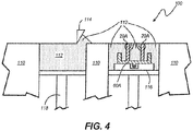
- FIG. 4 is a cross section view of additive manufacturing apparatus 100 along line C-C in FIG. 3 .
- FIG. 4 is a cutaway view that shows the operation of additive manufacturing apparatus 100.
- FIG. 4 shows a direct metal laser sintering (DMLS) apparatus, but it will be understood by those skilled in the art that other additive manufacturing techniques and apparatuses may be used, such as, for example, laser powder bed fusion, electron beam powder bed fusion, laser powder deposition, electron beam wire, selective laser sintering, or any other additive process.
- DMLS direct metal laser sintering
- Additive manufacturing apparatus 100 as shown in FIG. 4 includes many of the same parts as those shown in FIG. 3 , such as frame 110, pulverulent material 112, coater 114, and partially built ejector pump 20A.
- FIG. 4 also shows component support plate 116 and material supply support 118.
- Component support plate 116 may be used to raise or lower partially built ejector pump 20A.
- Material supply support 118 may be raised to elevate or lower pulverulent material 112 above the working surface of frame 110.
- FIG. 4 shows the arrangement of component support plate 116 and material supply support 118 in addition to the arrangement of parts shown in FIG. 3 .
- partially built ejector pump 20A rests on component support plate 116.
- pulverulent material 112 rests on material supply support 118.
- component support plate 116 is lowered and material supply support 118 is raised.
- Coater 114 scrapes a layer of pulverulent material 112 off of the top of the supply side and applies it in a layer across the top of partially built ejector pump 20A. The process is then repeated until ejector pump 20 (shown in FIGS. 2A-2C ) is complete.
- FIGS. 3-4 show one possible way of additively manufacturing ejector pump 20 as disclosed above in reference to FIGS. 2A-2C .
- Alternative methods for additively manufacturing components are possible.
- laser powder bed fusion, electron beam powder bed fusion, laser powder deposition, electron beam wire, or selective laser sintering may be used to create objects in an additive fashion.
- an additively manufactured ejector pump is faster to manufacture because there is no special tooling required. Similarly, if a design change needs to be made, that can be done simply and quickly. For another example, an ejector pump can be made with minimal post-processing requirements due to the lack of temporary support structures that would have otherwise needed to be added in order to employ an additive manufacturing process. Similarly, an ejector pump can be made using additive manufacturing while avoiding the addition of support structures that would be difficult or impossible to remove during post-processing.
- a method of making an additively manufactured ejector pump includes: creating a computer file defining the ejector pump in layers, the ejector pump comprising: a duct extending along a centerline from an upstream end to a downstream end; a nozzle extending inward from the duct including a flowpath therein; an annulus connected to the duct including a cavity therein; and at least one of the first group consisting of: a first gusset extending between the duct and the nozzle on a nozzle downstream side; wherein the flowpath comprises a cross-section with a flowpath shape of a semicircle on a nozzle upstream side and a peaked shape on the nozzle downstream side; and wherein the cavity comprises a cross-section with a cavity shape of quadrant of a circle on an annulus upstream side and a slant on an annulus downstream side; and building the ejector pump using an additive manufacturing process that builds the ejector
- the method of the preceding paragraph can optionally include, additionally and/or alternatively, any one or more of the following features, configurations and/or additional components:
- ejector pump can comprise at least two of the first group.
- a further embodiment of any of the foregoing methods, wherein the ejector pump can comprise all three of the first group.
- the ejector pump can further comprise: a platform connected to the duct; and a flange at the downstream end of the duct; and at least one of the second group consisting of: a second gusset extending between the duct and the platform on a platform upstream side; and wherein the flange extends from the duct at angle of about fifty degrees or less with respect to the centerline.
- ejector pump can comprise at least two of the first group.
- a further embodiment of any of the foregoing methods, wherein the ejector pump can comprise all three of the first group.
- ejector pump can comprise at least two of the first group.
- a further embodiment of any of the foregoing methods, wherein the ejector pump can comprise all three of the first group.
- annulus can be connected to a duct exterior.
- a monolithic ejector pump having an upstream end and a downstream end includes: a duct extending along a centerline from an upstream end to a downstream end, a nozzle extending inward from the duct including a flowpath therein, and an annulus connected to the duct including a cavity therein; the ejector pump being made by the steps of: selectively sintering a first layer of pulverulent material within a frame to make an initial layer of the upstream end of a partially built ejector pump; lowering the partially built ejector pump; adding a second layer of pulverulent material on top of the partially built ejector pump; and selectively sintering the second layer of pulverulent material to the partially built ejector pump.
- the ejector pump of the preceding paragraph can optionally include, additionally and/or alternatively, any one or more of the following features, configurations and/or additional components:
- the ejector pump can further comprise at least one of the first group consisting of: a first gusset extending between the duct and the nozzle on a nozzle downstream side; wherein the flowpath comprises a cross-section with a flowpath shape of a semicircle on a nozzle upstream side and a peaked shape on the nozzle downstream side; and wherein the cavity comprises a cross-section with a cavity shape of quadrant of a circle on an annulus upstream side and a slant on an annulus downstream side; and
- a further embodiment of any of the foregoing ejector pumps wherein the ejector pump an further comprise: a platform connected to the duct; and a flange at the downstream end of the duct.
- the ejector pump can further comprise at least one of the second group consisting of: a second gusset extending between the duct and the platform on a platform upstream side; and wherein the flange extends from the duct at angle of about fifty degrees or less with respect to the centerline.
- An ejector pump includes: a duct extending along a centerline from an upstream end to a downstream end; a nozzle extending inward from the duct including a flowpath therein; an annulus connected to the duct including a cavity therein; at least one of the first group consisting of: a first gusset extending between the duct and the nozzle on a nozzle downstream side; wherein the flowpath comprises a cross-section with a flowpath shape of a semicircle on a nozzle upstream side and a peaked shape on the nozzle downstream side; and wherein the cavity comprises a cross-section with a cavity shape of quadrant of a circle on an annulus upstream side and a slant on an annulus downstream side.
- the ejector pump of the preceding paragraph can optionally include, additionally and/or alternatively, any one or more of the following features, configurations and/or additional components:
- a further embodiment of the foregoing ejector pump wherein the ejector pump can further comprise: a platform connected to the duct; and a second gusset extending between the duct and the platform on a platform upstream side.
- the ejector pump can further comprise: a flange at the downstream end of the duct, wherein the flange extends from the duct at angle of about fifty degrees or less with respect to the centerline.
- annulus can be connected to a duct exterior.
Landscapes
- Engineering & Computer Science (AREA)
- Chemical & Material Sciences (AREA)
- Manufacturing & Machinery (AREA)
- Materials Engineering (AREA)
- Mechanical Engineering (AREA)
- General Engineering & Computer Science (AREA)
- Physics & Mathematics (AREA)
- Fluid Mechanics (AREA)
- Powder Metallurgy (AREA)
- Jet Pumps And Other Pumps (AREA)
- Producing Shaped Articles From Materials (AREA)
Abstract
Description
- The present invention relates generally to ejector pumps, and more particularly to an ejector made by additive manufacturing.
- Ejector pumps use the pressure energy from a high pressure source to increase the pressure and flow of a low pressure source. The high pressure source is directed through an ejector having nozzles which convert pressure energy to kinetic energy, and this high velocity flow entrains fluid from the low pressure source. The two streams experience pressure equalization and mixing downstream of the ejector leading to pressure recovery. Ejector pumps are beneficial because they have no moving parts and are relatively inexpensive and reliable, especially when a high pressure source is readily available. Conventional ejector pumps are fabricated either by machining and welding or by casting. Conventional manufacturing methods can be expensive, and it can be time consuming to change the tooling if a change is implemented to the design of the ejector pump.
- According to one embodiment, a method of making an additively manufactured ejector pump includes creating a computer file defining the ejector pump in layers. The ejector pump includes a duct extending along a centerline from an upstream end to a downstream end, a nozzle extending inward from the duct including a flowpath, an annulus connected to the duct including a cavity. The method also includes building the ejector pump using an additive manufacturing process that builds the ejector on a layer-by-layer basis from the upstream end to the downstream end.
- According to another embodiment, a monolithic ejector pump having an upstream end and a downstream end, the ejector pump including a duct extending along a centerline from an upstream end to a downstream end, a nozzle extending inward from the duct including a flowpath, and an annulus connected to the duct including a cavity. The ejector pump is made by the steps of: selectively sintering a first layer of pulverulent material within a frame to make an initial layer of the upstream end of a partially built ejector pump, lowering the partially built ejector pump, adding a second layer of pulverulent material on top of the partially built ejector pump, and selectively sintering the second layer of pulverulent material to the partially built ejector pump.
- According to another embodiment, an ejector pump includes a duct extending along a centerline from an upstream end to a downstream end, a nozzle extending inward from the duct including a flowpath therein, an annulus connected to the duct including a cavity therein. The ejector pump further includes at least one of the group consisting of: a first gusset extending between the duct and the nozzle on a nozzle downstream side; wherein the flowpath comprises a cross-section with a flowpath shape of a semicircle on a nozzle upstream side and a peaked shape on the nozzle downstream side; and wherein the cavity comprises a cross-section with a cavity shape of quadrant of a circle on an annulus upstream side and a slant on an annulus downstream side.
-
-
FIG. 1 is a schematic view of a heat exchanger system with an additively manufactured ejector pump. -
FIG. 2A is a perspective view of the ejector pump ofFIG. 1 . -
FIG. 2B is a cross-sectional view of the ejector pump ofFIG. 1 along line A-A inFIG. 2A . -
FIG. 2C is an enlarged cross-sectional view of the ejector pump ofFIG. 2B along line B-B inFIG. 2B . -
FIG. 3 is a perspective view of an additive manufacturing apparatus. -
FIG. 4 is a cross section view of the additive manufacturing apparatus along line C-C inFIG. 3 . - Shown in
FIG. 1 is a schematic view ofheat exchanger system 10 which includesfirst source 12,first inlet 14,heat exchanger 16,first outlet 18,ejector pump 20, andfirst destination 22 as the first fluid pathway.Heat exchanger system 10 also includessecond source 24,second inlet 26, heat exchanger 16 (again),second outlet 28, andsecond destination 30 as the second fluid pathway. In the illustrated embodiment,heat exchanger 16 is configured in a conventional manner that separates the two fluids (not shown) but encourages the transfer of heat therebetween. -
Heat exchanger system 10 further includes high-pressure source 32 which is connected toejector pump 20. In order to pump fluid fromfirst source 12 throughheat exchanger 16, fluid is released from high-pressure source 32 intoejector pump 20. As described in the Background section above, this fluid draws fluid fromfirst source 12 and both fluids flow tofirst destination 22. In the illustrated embodiment, only the first fluid pathway includes anejector pump 20, so fluid is pumped through the second pathway by some other conventional means (not shown). In an alternate embodiment, another ejector pump 20 (not shown) can be installed in the second fluid pathway to pump fluid fromsecond source 24 throughheat exchanger 16. Thisejector pump 20 can receive fluid from high-pressure source 32, or it can have its own high-pressure source (not shown). - Shown in
FIG. 2A is a perspective view ofejector pump 20. Shown inFIG. 2B is a cross-sectional view ofejector pump 20 along line A-A inFIG. 2A . Shown inFIG. 2C is an enlarged cross-sectional view ofejector pump 20 along line B-B inFIG. 2B .FIGS. 2A-2C will now be discussed simultaneously. - In the illustrated embodiment,
ejector pump 20 is a unitary, monolithic body manufactured using additive manufacturing techniques, as discussed later with respect toFIGS. 3 and4 .Ejector pump 20 is comprised of a single material or alloy with several integral structures,such nozzles 34 withgussets 36,annulus 38 withcavity 40,flange 42, andplatform 44. - In the illustrated embodiment,
ejector pump 20 comprisesduct 46 which extends alongcenterline 48. A plurality ofnozzles 34 extend inward from the interior ofduct 46.Initial portion 50 of eachnozzle 34 extends towardscenterline 48, perpendicular toduct 46; andexit portion 52 of eachnozzle 34 extends towards the downstream end ofduct 46, parallel tocenterline 48. The flow direction is denoted byarrow 54, which is also the direction in whichejector pump 20 is grown during manufacturing (as discussed below with respect toFIGS. 3 and4 ). In order to support eachnozzle 34 during manufacturing, agusset 36 connects the upstream side ofinitial portion 50 with the interior ofduct 46 at an angle θ1 of fifty degrees or less with respect tocenterline 48.Gussets 36 are aligned parallel tocenterline 48 as to not impede the flow of the fluid from heat exchanger 16 (shown inFIG. 1 ). There is only onegusset 36 connected to eachnozzle 34, although in alternate embodiments, there can beadditional gussets 36 attached to eachnozzle 34. - In addition, each
nozzle 34 includesflowpath 56 which is a hollow space through which the high-pressure fluid flows (as discussed above with respect toFIG. 1 ). The cross-sectional shape offlowpath 56 inexit portion 52 is circular, but the cross-sectional shape offlowpath 56 ininitial portion 50 is semicircular on the upstream side and peaked on the downstream side. Each leg of the peaked side extends at angle θ2 of about fifty degrees or less with respect tocenterline 48 and has a fillet joining the two legs at the downstream end. The peaked configuration allows for the peaked side ofinitial portion 50 to be grown by additive manufacturing without additional support structures, be they temporary or permanent. - In the illustrated embodiment, each
flowpath 56 extends throughduct 46 and is fluidly connected tocavity 40.Cavity 40 is a hollow space inannulus 38 through which the high-pressure fluid flows (as discussed above with respect toFIG. 1 ), allowing the high-pressure fluid to be distributed to all of thenozzles 34.Cavity 40 has a shape that is flat alongsideduct 46 on the inner side with a compound shape on the outer side. The outer side is a quadrant of a circle on the upstream side and slanted towardduct 46 on the downstream side, with two interior fillets whereannulus 38 meetsduct 46. As withinitial portion 50, the slanted side has angle θ3 of about fifty degrees or less with respect tocenterline 48 so thatannulus 38 can be grown by additive manufacturing without additional internal support structures. In addition, the exterior ofannulus 38 has a fillet on the upstream side whereannulus 38 connects to the exterior ofduct 46, then annulus 38 has a shape that is offset from the shape of cavity 40 (i.e., circular on the upstream side and linear on the downstream side), andannulus 38 terminates with another fillet whereannulus 38 connects toduct 46 again. - In the illustrated embodiment,
ejector pump 20 hasflange 42 at the downstream end ofduct 46.Flange 42 is a thickened section that can be machined and/or welded to attachejector pump 20 to other components in heat exchanger system 10 (shown inFIG. 1 ). More specifically,flange 42 extends fromduct 46 at angle θ4 of about fifty degrees or less with respect tocenterline 48 so thatflange 42 can be grown by additive manufacturing without additional support structures, be they temporary or permanent. However,flange 42 terminates abruptly with an annular surface that is perpendicular tocenterline 48. -
Ejector pump 20 further includesplatform 44.Platform 44 extends from the exterior ofduct 46 is configured to be an interface to connectejector pump 20 with high-pressure source 32. More specifically,platform 44 has a flat outer surface that is parallel to centerline 48 and can be made solid during the additive manufacturing process. Subsequently a port can be drilled throughplatform 44, intocavity 40, and a fitting can be threaded into or welded ontoplatform 44 to connectejector pump 20 to high-pressure source 32. The port inplatform 44 allows the high-pressure fluid from high-pressure source 32 to travel intocavity 40. As withnozzles 34,platform 44 includesgusset 58 which connects the upstream side ofplatform 44 with the exterior ofduct 46 at an angle θ5 of fifty degrees or less with respect tocenterline 48.Gusset 58supports platform 44 during manufacturing ofejector pump 20 so no additional support structures are necessary, including temporary support structures. There is only onegusset 58, although in alternate embodiments, there can beadditional gussets 58 connected toplatform 44. - The configuration of
ejector pump 20 allows for use of an additive manufacturing process without needing temporary supporting structures to be made and without permanent supporting structures within the flow areas of the high-pressure fluid (i.e., withinplatform 44,cavity 40, orflowpaths 56. Thereby, no post-processing steps are needed to remove temporary supports, and there are no unnecessary structures impeding the flow of the high-pressure fluid. -
FIG. 3 is a perspective view ofadditive manufacturing apparatus 100. In particular,FIG. 3 shows an additive manufacturing apparatus which uses laser additive manufacturing to create a three-dimensional object out of sinterable, pulverulent material. While direct metal laser sintering (DMLS) is described, other additive manufacturing techniques may be employed, such as, for example, laser powder bed fusion, electron beam powder bed fusion, laser powder deposition, electron beam wire, selective laser sintering, or any other additive process. -
Additive manufacturing apparatus 100 includescomputer 101 and a set of optical components, includinglaser 102,mirror 104, and movingoptical head 106, which guidelaser beam 108 according to the instructions fromcomputer 101.Laser 102 may be any source of heating radiation, such as a CO2 laser.Additive manufacturing apparatus 100 also includesframe 110,pulverulent material 112, andcoater 114, which are used for powder containment and application.Pulverulent material 112 may be any material suitable for use as an ejector. Typically,pulverulent material 112 will be one or more metal materials or alloys. For example,pulverulent material 112 may be steel, stainless steel, or a high temperature superalloy.Coater 114 is arranged along a surface offrame 110, and may be moved across the surface offrame 110.Coater 114 may be, for example, a knife blade or a roller. As shown inFIG. 3 , partially builtejector pump 20A is presentinside frame 110. - A user creates a computer file for
computer 101 that defines a component with particular features, such as ejector pump 20 (shown inFIGS. 2A-2C ), in layers (that can be of different thicknesses).Computer 101 then controls the optical equipment to create the component.Laser 102 createslaser beam 108 which can be used for melting, sintering, or cutting.Laser 102 is pointed towardsmirror 104, which is arranged to deflectlaser beam 108 toward movingoptical head 106. Generally, movingoptical head 106 directslaser beam 108 towards areas withinframe 110, which holdspulverulent material 112. Generally, the areas melted or sintered form a layer ofejector pump 20. InFIG. 3 , partially builtejector pump 20A is shown being built up on a layer-by-layer basis. Areas adjacent to partially builtejector pump 20A can remain unmelted or unsintered to formnozzles 34 and annulus 38 (shown inFIGS. 2B and2C ). - After each layer of partially built
ejector pump 20A is finished, the support holding partially built ejector pump 20A (shown later inFIG. 4 ) is lowered by the thickness of one layer ofpulverulent material 112, and additionalpulverulent material 112 is added on top of the existingstructures using coater 114. Then new layer ofpulverulent material 112 is melted or sintered to the top of partially builtejector pump 20A, and the process is repeated. By repeating the process several times, a layer-by-layer object, such as acomplete ejector pump 20 can be manufactured. - In order to make ejector pump 20 ready for service, there may need to be post-processing performed. For example, unsintered pulverulent material inside of the cavities (e.g.,
cavity 40 andflowpaths 56, shown inFIGS. 2B and2C ) ofejector pump 20 may need to be removed, for example, using high-pressure gas to blow it out. For another example, nozzles 34 (shown inFIGS. 2A-2C ) may need to be polished inside and/or outside with abrasive material. Alternatively, these areas ofejector pump 20 can be additively manufactured using different parameters than the bulk ofejector pump 20 to ensure a fine surface finish without extra post-processing required. However, as discussed previously, no removal of temporary support structures will be needed, at least not with respect tonozzles 34,annulus 38,flange 42, orplatform 44. -
FIG. 4 is a cross section view ofadditive manufacturing apparatus 100 along line C-C inFIG. 3 .FIG. 4 is a cutaway view that shows the operation ofadditive manufacturing apparatus 100.FIG. 4 shows a direct metal laser sintering (DMLS) apparatus, but it will be understood by those skilled in the art that other additive manufacturing techniques and apparatuses may be used, such as, for example, laser powder bed fusion, electron beam powder bed fusion, laser powder deposition, electron beam wire, selective laser sintering, or any other additive process. -
Additive manufacturing apparatus 100 as shown inFIG. 4 includes many of the same parts as those shown inFIG. 3 , such asframe 110,pulverulent material 112,coater 114, and partially builtejector pump 20A.FIG. 4 also showscomponent support plate 116 andmaterial supply support 118.Component support plate 116 may be used to raise or lower partially builtejector pump 20A.Material supply support 118 may be raised to elevate or lowerpulverulent material 112 above the working surface offrame 110. -
FIG. 4 shows the arrangement ofcomponent support plate 116 andmaterial supply support 118 in addition to the arrangement of parts shown inFIG. 3 . As can be seen inFIG. 4 , partially builtejector pump 20A rests oncomponent support plate 116. Likewise,pulverulent material 112 rests onmaterial supply support 118. - As each layer of partially built
ejector pump 20A is melted or sintered,component support plate 116 is lowered andmaterial supply support 118 is raised.Coater 114 scrapes a layer ofpulverulent material 112 off of the top of the supply side and applies it in a layer across the top of partially builtejector pump 20A. The process is then repeated until ejector pump 20 (shown inFIGS. 2A-2C ) is complete. -
FIGS. 3-4 show one possible way of additively manufacturingejector pump 20 as disclosed above in reference toFIGS. 2A-2C . Alternative methods for additively manufacturing components are possible. For example, laser powder bed fusion, electron beam powder bed fusion, laser powder deposition, electron beam wire, or selective laser sintering may be used to create objects in an additive fashion. - It should be recognized that the present invention provides numerous benefits and advantages. For example, an additively manufactured ejector pump is faster to manufacture because there is no special tooling required. Similarly, if a design change needs to be made, that can be done simply and quickly. For another example, an ejector pump can be made with minimal post-processing requirements due to the lack of temporary support structures that would have otherwise needed to be added in order to employ an additive manufacturing process. Similarly, an ejector pump can be made using additive manufacturing while avoiding the addition of support structures that would be difficult or impossible to remove during post-processing.
- The following are non-exclusive descriptions of possible embodiments of the present invention.
- A method of making an additively manufactured ejector pump according to an exemplary embodiment of this disclosure, among other possible things includes: creating a computer file defining the ejector pump in layers, the ejector pump comprising: a duct extending along a centerline from an upstream end to a downstream end; a nozzle extending inward from the duct including a flowpath therein; an annulus connected to the duct including a cavity therein; and at least one of the first group consisting of: a first gusset extending between the duct and the nozzle on a nozzle downstream side; wherein the flowpath comprises a cross-section with a flowpath shape of a semicircle on a nozzle upstream side and a peaked shape on the nozzle downstream side; and wherein the cavity comprises a cross-section with a cavity shape of quadrant of a circle on an annulus upstream side and a slant on an annulus downstream side; and building the ejector pump using an additive manufacturing process that builds the ejector on a layer-by-layer basis from the upstream end to the downstream end such that there are no temporary support structures associated with the at least one of the group.
- The method of the preceding paragraph can optionally include, additionally and/or alternatively, any one or more of the following features, configurations and/or additional components:
- A further embodiment of the foregoing method, wherein the ejector pump can comprise at least two of the first group.
- A further embodiment of any of the foregoing methods, wherein the ejector pump can comprise all three of the first group.
- A further embodiment of any of the foregoing methods, wherein the ejector pump can further comprise: a platform connected to the duct; and a flange at the downstream end of the duct; and at least one of the second group consisting of: a second gusset extending between the duct and the platform on a platform upstream side; and wherein the flange extends from the duct at angle of about fifty degrees or less with respect to the centerline.
- A further embodiment of any of the foregoing methods, wherein the ejector pump can comprise at least two of the first group.
- A further embodiment of any of the foregoing methods, wherein the ejector pump can comprise all three of the first group.
- A further embodiment of any of the foregoing methods, wherein the ejector pump can comprise both of the second group.
- A further embodiment of any of the foregoing methods, wherein the ejector pump can comprise at least two of the first group.
- A further embodiment of any of the foregoing methods, wherein the ejector pump can comprise all three of the first group.
- A further embodiment of any of the foregoing methods, wherein the annulus can be connected to a duct exterior.
- A monolithic ejector pump having an upstream end and a downstream end according to an exemplary embodiment of this disclosure, among other possible things includes: a duct extending along a centerline from an upstream end to a downstream end, a nozzle extending inward from the duct including a flowpath therein, and an annulus connected to the duct including a cavity therein; the ejector pump being made by the steps of: selectively sintering a first layer of pulverulent material within a frame to make an initial layer of the upstream end of a partially built ejector pump; lowering the partially built ejector pump; adding a second layer of pulverulent material on top of the partially built ejector pump; and selectively sintering the second layer of pulverulent material to the partially built ejector pump.
- The ejector pump of the preceding paragraph can optionally include, additionally and/or alternatively, any one or more of the following features, configurations and/or additional components:
- A further embodiment of the foregoing ejector pump, wherein the ejector pump can further comprise at least one of the first group consisting of: a first gusset extending between the duct and the nozzle on a nozzle downstream side; wherein the flowpath comprises a cross-section with a flowpath shape of a semicircle on a nozzle upstream side and a peaked shape on the nozzle downstream side; and wherein the cavity comprises a cross-section with a cavity shape of quadrant of a circle on an annulus upstream side and a slant on an annulus downstream side; and
- A further embodiment of any of the foregoing ejector pumps, wherein a first gusset layer can be made before a first nozzle layer is made.
- A further embodiment of any of the foregoing ejector pumps, wherein the ejector pump can further comprise at least two of the first group.
- A further embodiment of any of the foregoing ejector pumps, wherein the ejector pump an further comprise: a platform connected to the duct; and a flange at the downstream end of the duct.
- A further embodiment of any of the foregoing ejector pumps, wherein the ejector pump can further comprise at least one of the second group consisting of: a second gusset extending between the duct and the platform on a platform upstream side; and wherein the flange extends from the duct at angle of about fifty degrees or less with respect to the centerline.
- An ejector pump according to an exemplary embodiment of this disclosure, among other possible things includes: a duct extending along a centerline from an upstream end to a downstream end; a nozzle extending inward from the duct including a flowpath therein; an annulus connected to the duct including a cavity therein; at least one of the first group consisting of: a first gusset extending between the duct and the nozzle on a nozzle downstream side; wherein the flowpath comprises a cross-section with a flowpath shape of a semicircle on a nozzle upstream side and a peaked shape on the nozzle downstream side; and wherein the cavity comprises a cross-section with a cavity shape of quadrant of a circle on an annulus upstream side and a slant on an annulus downstream side.
- The ejector pump of the preceding paragraph can optionally include, additionally and/or alternatively, any one or more of the following features, configurations and/or additional components:
- A further embodiment of the foregoing ejector pump, wherein the ejector pump can further comprise: a platform connected to the duct; and a second gusset extending between the duct and the platform on a platform upstream side.
- A further embodiment of any of the foregoing ejector pumps, wherein the ejector pump can further comprise: a flange at the downstream end of the duct, wherein the flange extends from the duct at angle of about fifty degrees or less with respect to the centerline.
- A further embodiment of any of the foregoing ejector pumps, wherein the annulus can be connected to a duct exterior.
- While the invention has been described with reference to an exemplary embodiment(s), it will be understood by those skilled in the art that various changes may be made and equivalents may be substituted for elements thereof without departing from the scope of the invention. In addition, many modifications may be made to adapt a particular situation or material to the teachings of the invention without departing from the essential scope thereof. Therefore, it is intended that the invention not be limited to the particular embodiment(s) disclosed, but that the invention will include all embodiments falling within the scope of the appended claims.
Claims (15)
- A method of making an additively manufactured ejector pump (20), the method comprising:creating a computer file defining the ejector pump (20) in layers, the ejector pump (20) comprising:a duct (46) extending along a centerline from an upstream end to a downstream end;a nozzle (34) extending inward from the duct including a flowpath therein;an annulus (38) connected to the duct (46) including a cavity therein; andat least one of the first group consisting of:a first gusset (36) extending between the duct (46) and the nozzle (34) on a nozzle downstream side;wherein the flowpath comprises a cross-section with a flowpath shape of a semicircle on a nozzle upstream side and a peaked shape on the nozzle downstream side; andwherein the cavity (40) comprises a cross-section with a cavity shape of quadrant of a circle on an annulus upstream side and a slant on an annulus downstream side; andbuilding the ejector pump (20) using an additive manufacturing process that builds the ejector on a layer-by-layer basis from the upstream end to the downstream end such that there are no temporary support structures associated with the at least one of the group.
- The method of claim 1, wherein the ejector pump (20) further comprises:a platform (44) connected to the duct (46); anda flange at the downstream end of the duct (46); andat least one of the second group consisting of:a second gusset (36) extending between the duct and the platform on a platform upstream side; andwherein the flange extends from the duct (46) at angle of about fifty degrees or less with respect to the centerline.
- The method of claim 1 or 2, wherein the ejector pump (20) comprises at least two of the first group.
- The method of claim 1 or 2, wherein the ejector pump (20) comprises all three of the first group.
- The method of any of claims 2 to 4, wherein the ejector pump (20) comprises both of the second group.
- The method of any preceding claim, wherein the annulus is connected to a duct exterior.
- A monolithic ejector pump having an upstream end and a downstream end, the ejector pump comprising: a duct (46) extending along a centerline from an upstream end to a downstream end, a nozzle extending inward from the duct (46) including a flowpath therein, and an annulus connected to the duct (46) including a cavity therein; the ejector pump (20) being made by the steps of:selectively sintering a first layer of pulverulent material within a frame to make an initial layer of the upstream end of a partially built ejector pump (20);lowering the partially built ejector pump (20);adding a second layer of pulverulent material on top of the partially built ejector pump (20); andselectively sintering the second layer of pulverulent material to the partially built ejector pump (20).
- The ejector pump of claim 7, further comprising at least one of the first group consisting of:a first gusset (36) extending between the duct and the nozzle on a nozzle downstream side;wherein the flowpath comprises a cross-section with a flowpath shape of a semicircle on a nozzle upstream side and a peaked shape on the nozzle downstream side; andwherein the cavity (40) comprises a cross-section with a cavity shape of quadrant of a circle on an annulus upstream side and a slant on an annulus downstream side.
- The ejector pump of claim 8, wherein a first gusset layer is made before a first nozzle layer is made.
- The ejector pump of claim 8 or 9, further comprising at least two of the first group.
- The ejector pump of any preceding claim, wherein the ejector pump further comprises:a platform (44) connected to the duct (46); anda flange at the downstream end of the duct, and preferably further comprising at least one of the second group consisting of:a second gusset (36) extending between the duct (46) and the platform on a platform upstream side; andwherein the flange extends from the duct (46) at angle of about fifty degrees or less with respect to the centerline.
- An ejector pump (20) comprising:a duct (46) extending along a centerline from an upstream end to a downstream end;a nozzle extending inward from the duct (46) including a flowpath therein;an annulus connected to the duct including a cavity therein;at least one of the first group consisting of:a first gusset (36) extending between the duct (46) and the nozzle on a nozzle downstream side;wherein the flowpath comprises a cross-section with a flowpath shape of a semicircle on a nozzle upstream side and a peaked shape on the nozzle downstream side; andwherein the cavity comprises a cross-section with a cavity shape of quadrant of a circle on an annulus upstream side and a slant on an annulus downstream side.
- The ejector pump of claim 12, further comprising:a platform (44) connected to the duct (46); anda second gusset (36) extending between the duct and the platform on a platform upstream side.
- The ejector pump of claim 12 or 13, further comprising:a flange at the downstream end of the duct (46), wherein the flange extends from the duct (46) at angle of about fifty degrees or less with respect to the centerline.
- The ejector pump of claim 12, 13 or 14, wherein the annulus is connected to a duct exterior.
Priority Applications (1)
| Application Number | Priority Date | Filing Date | Title |
|---|---|---|---|
| EP23155649.9A EP4198320A1 (en) | 2018-01-05 | 2019-01-07 | Additively manufactured ejector pump |
Applications Claiming Priority (1)
| Application Number | Priority Date | Filing Date | Title |
|---|---|---|---|
| US15/863,561 US10962028B2 (en) | 2018-01-05 | 2018-01-05 | Additively manufactured ejector pump |
Related Child Applications (1)
| Application Number | Title | Priority Date | Filing Date |
|---|---|---|---|
| EP23155649.9A Division EP4198320A1 (en) | 2018-01-05 | 2019-01-07 | Additively manufactured ejector pump |
Publications (3)
| Publication Number | Publication Date |
|---|---|
| EP3508735A2 true EP3508735A2 (en) | 2019-07-10 |
| EP3508735A3 EP3508735A3 (en) | 2019-08-28 |
| EP3508735B1 EP3508735B1 (en) | 2023-03-01 |
Family
ID=65009632
Family Applications (2)
| Application Number | Title | Priority Date | Filing Date |
|---|---|---|---|
| EP23155649.9A Withdrawn EP4198320A1 (en) | 2018-01-05 | 2019-01-07 | Additively manufactured ejector pump |
| EP19150573.4A Active EP3508735B1 (en) | 2018-01-05 | 2019-01-07 | Additively manufactured ejector pump |
Family Applications Before (1)
| Application Number | Title | Priority Date | Filing Date |
|---|---|---|---|
| EP23155649.9A Withdrawn EP4198320A1 (en) | 2018-01-05 | 2019-01-07 | Additively manufactured ejector pump |
Country Status (2)
| Country | Link |
|---|---|
| US (1) | US10962028B2 (en) |
| EP (2) | EP4198320A1 (en) |
Families Citing this family (12)
| Publication number | Priority date | Publication date | Assignee | Title |
|---|---|---|---|---|
| DE102018207594A1 (en) | 2018-05-16 | 2019-11-21 | Kardion Gmbh | Rotor, magnetic coupling device, electric motor for a cardiac assist system, pump unit for a cardiac assist system and method for manufacturing a rotor |
| DE102018208539A1 (en) | 2018-05-30 | 2019-12-05 | Kardion Gmbh | A motor housing module for sealing an engine compartment of a motor of a cardiac assist system and cardiac assistance system and method for mounting a cardiac assist system |
| DE102018208549A1 (en) | 2018-05-30 | 2019-12-05 | Kardion Gmbh | Electronic module for a cardiac assist system and method for manufacturing an electronic module for a cardiac assist system |
| DE102018208550A1 (en) | 2018-05-30 | 2019-12-05 | Kardion Gmbh | A lead device for directing blood flow to a cardiac assist system, cardiac assist system, and method of making a lead device |
| DE102018210058A1 (en) | 2018-06-21 | 2019-12-24 | Kardion Gmbh | Stator blade device for guiding the flow of a fluid flowing out of an outlet opening of a heart support system, heart support system with stator blade device, method for operating a stator blade device and manufacturing method |
| DE102018211297A1 (en) | 2018-07-09 | 2020-01-09 | Kardion Gmbh | Cardiac support system and method for monitoring the integrity of a support structure of a cardiac support system |
| DE102018211327A1 (en) | 2018-07-10 | 2020-01-16 | Kardion Gmbh | Impeller for an implantable vascular support system |
| DE102018211328A1 (en) | 2018-07-10 | 2020-01-16 | Kardion Gmbh | Impeller housing for an implantable vascular support system |
| ES3055124T3 (en) | 2018-08-07 | 2026-02-10 | Kardion Gmbh | Bearing device for a heart support system, and method for rinsing a space in a bearing device for a heart support system |
| DE102020102474A1 (en) * | 2020-01-31 | 2021-08-05 | Kardion Gmbh | Pump for conveying a fluid and method for manufacturing a pump |
| JP7744043B2 (en) | 2020-09-14 | 2025-09-25 | カルディオン ゲーエムベーハー | Cardiovascular assist pump having an impeller with variable flow area |
| US12589237B2 (en) | 2020-11-20 | 2026-03-31 | Kardion Gmbh | Mechanical circulatory support system with guidewire aid |
Family Cites Families (28)
| Publication number | Priority date | Publication date | Assignee | Title |
|---|---|---|---|---|
| US2172522A (en) * | 1939-09-12 | Safety breather for aircraft | ||
| US1543834A (en) * | 1922-03-02 | 1925-06-30 | Elliott Co | Ejector |
| US1574677A (en) * | 1924-08-23 | 1926-02-23 | Mulder Jakob | Ejector for the delivery of gas and air in large quantities |
| US1724625A (en) * | 1924-11-14 | 1929-08-13 | Robert P Sweeny | Pneumatic cleaning apparatus |
| US1648238A (en) * | 1927-01-22 | 1927-11-08 | Modra William | Siphon pump |
| US1671851A (en) * | 1927-08-06 | 1928-05-29 | K W Dennis | Injector |
| US2061032A (en) * | 1935-11-23 | 1936-11-17 | Thomas H Huff | Jet pump |
| US2111266A (en) * | 1936-12-28 | 1938-03-15 | Thomas S Hopkins | Draft inducer |
| DE954545C (en) | 1954-10-13 | 1956-12-20 | Stamicarbon | Jet machine |
| US3188009A (en) * | 1962-04-26 | 1965-06-08 | Stang Corp John W | Variable spray nozzle |
| US3468472A (en) * | 1967-09-15 | 1969-09-23 | Global Systems | Flow augmented nozzle |
| US3460747A (en) * | 1968-11-05 | 1969-08-12 | Rocket Research Corp | Inflation method and apparatus |
| US3554450A (en) * | 1968-11-15 | 1971-01-12 | Thomas F D Muhala | Spray gun with replaceable cartridges |
| US4400138A (en) * | 1981-10-19 | 1983-08-23 | Baer William F | Multiple jet eductor |
| US4815942A (en) * | 1982-10-25 | 1989-03-28 | Elayne P. Alperin | Axially-symmetric, jet-diffuser ejector |
| JP2713814B2 (en) * | 1990-11-15 | 1998-02-16 | 三井造船株式会社 | Ejector for compressible fluid |
| US5510066A (en) * | 1992-08-14 | 1996-04-23 | Guild Associates, Inc. | Method for free-formation of a free-standing, three-dimensional body |
| US5417550A (en) * | 1993-11-02 | 1995-05-23 | Marine Gikens Co., Ltd. | Submersed jet pump for generating a stream of water |
| DE19606128A1 (en) * | 1996-02-20 | 1997-08-21 | Eos Electro Optical Syst | Device and method for producing a three-dimensional object |
| EP2715253B1 (en) | 2011-05-23 | 2019-11-06 | Carrier Corporation | Ejectors and methods of manufacture |
| US9598146B2 (en) * | 2013-06-26 | 2017-03-21 | Doug Palmisano | Static bilge pump |
| US9505057B2 (en) * | 2013-09-06 | 2016-11-29 | Arcam Ab | Powder distribution in additive manufacturing of three-dimensional articles |
| GB2546016B (en) * | 2014-06-20 | 2018-11-28 | Velo3D Inc | Apparatuses, systems and methods for three-dimensional printing |
| US10260530B2 (en) * | 2014-10-10 | 2019-04-16 | Circor Aerospace, Inc. | Aspirator and method of fabricating |
| CA2992318A1 (en) | 2015-07-13 | 2017-01-19 | Source Rock Energy Partners Inc. | Jet pump manufactured using additive and subtractive machining techniques |
| CN107921707A (en) * | 2015-07-17 | 2018-04-17 | 应用材料公司 | Additive manufacturing with coolant system |
| US10344778B2 (en) * | 2016-02-29 | 2019-07-09 | Haier Us Appliance Solutions, Inc. | Ejector for a sealed system |
| US11174878B2 (en) * | 2017-01-13 | 2021-11-16 | Goodrich Corporation | Aspirator system |
-
2018
- 2018-01-05 US US15/863,561 patent/US10962028B2/en active Active
-
2019
- 2019-01-07 EP EP23155649.9A patent/EP4198320A1/en not_active Withdrawn
- 2019-01-07 EP EP19150573.4A patent/EP3508735B1/en active Active
Non-Patent Citations (1)
| Title |
|---|
| None |
Also Published As
| Publication number | Publication date |
|---|---|
| EP4198320A1 (en) | 2023-06-21 |
| EP3508735A3 (en) | 2019-08-28 |
| EP3508735B1 (en) | 2023-03-01 |
| US20190211847A1 (en) | 2019-07-11 |
| US10962028B2 (en) | 2021-03-30 |
Similar Documents
| Publication | Publication Date | Title |
|---|---|---|
| EP3508735B1 (en) | Additively manufactured ejector pump | |
| CA2946547C (en) | Additive manufacturing method for making complex film holes | |
| CN1896463B (en) | Niobium silicide-based turbine components and related laser deposition method | |
| EP2746589A2 (en) | Additively manufactured impeller | |
| US20160023272A1 (en) | Turbulating cooling structures | |
| CN109070217B (en) | An additive machine that builds surfaces using rotation | |
| US11248491B2 (en) | Additively deposited gas turbine engine cooling component | |
| US20150322800A1 (en) | Gas path components of gas turbine engines and methods for cooling the same using porous medium cooling systems | |
| US10914185B2 (en) | Additive manufactured case with internal passages for active clearance control | |
| US20200355304A1 (en) | Flexible, thermal-isolating, dual-walled tube with bellows and method for manufacture thereof | |
| US9597732B2 (en) | Flow restrictor assemblies including a monolithic flow restrictor and methods for manufacturing the same | |
| US12053821B2 (en) | Engine article with integral liner and nozzle | |
| EP2772688A2 (en) | A vane structure and a method of manufacturing a vane structure | |
| US20170368647A1 (en) | Methods for repairing film holes in a surface | |
| CA2946590A1 (en) | Additive manufacturing method for making overhanging tabs in cooling holes | |
| JP7317944B2 (en) | Method of forming a hot gas path component for a gas turbine engine | |
| CA2992318A1 (en) | Jet pump manufactured using additive and subtractive machining techniques | |
| EP2239083A1 (en) | Internally supported airfoil and method for internally supporting a hollow airfoil during manufacturing. | |
| EP1985800A2 (en) | Dimensional restoration of turbine blade knife edge seals | |
| CN106194434A (en) | There is the turbine component of cooling duct, surface and form its method | |
| US20170080526A1 (en) | Additive manufacturing using cast strip superalloy material | |
| US12497978B2 (en) | Manufacture of a stage casing in a hybrid process | |
| US20170008135A1 (en) | Systems and methods for refurbishing a plunger of a gas well system |
Legal Events
| Date | Code | Title | Description |
|---|---|---|---|
| PUAI | Public reference made under article 153(3) epc to a published international application that has entered the european phase |
Free format text: ORIGINAL CODE: 0009012 |
|
| STAA | Information on the status of an ep patent application or granted ep patent |
Free format text: STATUS: THE APPLICATION HAS BEEN PUBLISHED |
|
| AK | Designated contracting states |
Kind code of ref document: A2 Designated state(s): AL AT BE BG CH CY CZ DE DK EE ES FI FR GB GR HR HU IE IS IT LI LT LU LV MC MK MT NL NO PL PT RO RS SE SI SK SM TR |
|
| AX | Request for extension of the european patent |
Extension state: BA ME |
|
| PUAL | Search report despatched |
Free format text: ORIGINAL CODE: 0009013 |
|
| AK | Designated contracting states |
Kind code of ref document: A3 Designated state(s): AL AT BE BG CH CY CZ DE DK EE ES FI FR GB GR HR HU IE IS IT LI LT LU LV MC MK MT NL NO PL PT RO RS SE SI SK SM TR |
|
| AX | Request for extension of the european patent |
Extension state: BA ME |
|
| RIC1 | Information provided on ipc code assigned before grant |
Ipc: F04F 5/46 20060101AFI20190724BHEP |
|
| STAA | Information on the status of an ep patent application or granted ep patent |
Free format text: STATUS: REQUEST FOR EXAMINATION WAS MADE |
|
| 17P | Request for examination filed |
Effective date: 20191217 |
|
| RBV | Designated contracting states (corrected) |
Designated state(s): AL AT BE BG CH CY CZ DE DK EE ES FI FR GB GR HR HU IE IS IT LI LT LU LV MC MK MT NL NO PL PT RO RS SE SI SK SM TR |
|
| STAA | Information on the status of an ep patent application or granted ep patent |
Free format text: STATUS: EXAMINATION IS IN PROGRESS |
|
| 17Q | First examination report despatched |
Effective date: 20201019 |
|
| GRAP | Despatch of communication of intention to grant a patent |
Free format text: ORIGINAL CODE: EPIDOSNIGR1 |
|
| STAA | Information on the status of an ep patent application or granted ep patent |
Free format text: STATUS: GRANT OF PATENT IS INTENDED |
|
| RIC1 | Information provided on ipc code assigned before grant |
Ipc: B33Y 80/00 20150101ALI20220318BHEP Ipc: B33Y 10/00 20150101ALI20220318BHEP Ipc: B22F 10/20 20210101ALI20220318BHEP Ipc: B22F 3/105 20060101ALI20220318BHEP Ipc: F04F 5/46 20060101AFI20220318BHEP |
|
| INTG | Intention to grant announced |
Effective date: 20220419 |
|
| GRAJ | Information related to disapproval of communication of intention to grant by the applicant or resumption of examination proceedings by the epo deleted |
Free format text: ORIGINAL CODE: EPIDOSDIGR1 |
|
| STAA | Information on the status of an ep patent application or granted ep patent |
Free format text: STATUS: EXAMINATION IS IN PROGRESS |
|
| INTC | Intention to grant announced (deleted) | ||
| GRAP | Despatch of communication of intention to grant a patent |
Free format text: ORIGINAL CODE: EPIDOSNIGR1 |
|
| STAA | Information on the status of an ep patent application or granted ep patent |
Free format text: STATUS: GRANT OF PATENT IS INTENDED |
|
| INTG | Intention to grant announced |
Effective date: 20220922 |
|
| GRAS | Grant fee paid |
Free format text: ORIGINAL CODE: EPIDOSNIGR3 |
|
| GRAA | (expected) grant |
Free format text: ORIGINAL CODE: 0009210 |
|
| STAA | Information on the status of an ep patent application or granted ep patent |
Free format text: STATUS: THE PATENT HAS BEEN GRANTED |
|
| AK | Designated contracting states |
Kind code of ref document: B1 Designated state(s): AL AT BE BG CH CY CZ DE DK EE ES FI FR GB GR HR HU IE IS IT LI LT LU LV MC MK MT NL NO PL PT RO RS SE SI SK SM TR |
|
| REG | Reference to a national code |
Ref country code: GB Ref legal event code: FG4D |
|
| REG | Reference to a national code |
Ref country code: CH Ref legal event code: EP Ref country code: AT Ref legal event code: REF Ref document number: 1551154 Country of ref document: AT Kind code of ref document: T Effective date: 20230315 |
|
| REG | Reference to a national code |
Ref country code: DE Ref legal event code: R096 Ref document number: 602019025708 Country of ref document: DE |
|
| REG | Reference to a national code |
Ref country code: IE Ref legal event code: FG4D |
|
| REG | Reference to a national code |
Ref country code: LT Ref legal event code: MG9D |
|
| P01 | Opt-out of the competence of the unified patent court (upc) registered |
Effective date: 20230522 |
|
| REG | Reference to a national code |
Ref country code: NL Ref legal event code: MP Effective date: 20230301 |
|
| PG25 | Lapsed in a contracting state [announced via postgrant information from national office to epo] |
Ref country code: RS Free format text: LAPSE BECAUSE OF FAILURE TO SUBMIT A TRANSLATION OF THE DESCRIPTION OR TO PAY THE FEE WITHIN THE PRESCRIBED TIME-LIMIT Effective date: 20230301 Ref country code: NO Free format text: LAPSE BECAUSE OF FAILURE TO SUBMIT A TRANSLATION OF THE DESCRIPTION OR TO PAY THE FEE WITHIN THE PRESCRIBED TIME-LIMIT Effective date: 20230601 Ref country code: LV Free format text: LAPSE BECAUSE OF FAILURE TO SUBMIT A TRANSLATION OF THE DESCRIPTION OR TO PAY THE FEE WITHIN THE PRESCRIBED TIME-LIMIT Effective date: 20230301 Ref country code: LT Free format text: LAPSE BECAUSE OF FAILURE TO SUBMIT A TRANSLATION OF THE DESCRIPTION OR TO PAY THE FEE WITHIN THE PRESCRIBED TIME-LIMIT Effective date: 20230301 Ref country code: HR Free format text: LAPSE BECAUSE OF FAILURE TO SUBMIT A TRANSLATION OF THE DESCRIPTION OR TO PAY THE FEE WITHIN THE PRESCRIBED TIME-LIMIT Effective date: 20230301 Ref country code: ES Free format text: LAPSE BECAUSE OF FAILURE TO SUBMIT A TRANSLATION OF THE DESCRIPTION OR TO PAY THE FEE WITHIN THE PRESCRIBED TIME-LIMIT Effective date: 20230301 |
|
| REG | Reference to a national code |
Ref country code: AT Ref legal event code: MK05 Ref document number: 1551154 Country of ref document: AT Kind code of ref document: T Effective date: 20230301 |
|
| PG25 | Lapsed in a contracting state [announced via postgrant information from national office to epo] |
Ref country code: SE Free format text: LAPSE BECAUSE OF FAILURE TO SUBMIT A TRANSLATION OF THE DESCRIPTION OR TO PAY THE FEE WITHIN THE PRESCRIBED TIME-LIMIT Effective date: 20230301 Ref country code: PL Free format text: LAPSE BECAUSE OF FAILURE TO SUBMIT A TRANSLATION OF THE DESCRIPTION OR TO PAY THE FEE WITHIN THE PRESCRIBED TIME-LIMIT Effective date: 20230301 Ref country code: NL Free format text: LAPSE BECAUSE OF FAILURE TO SUBMIT A TRANSLATION OF THE DESCRIPTION OR TO PAY THE FEE WITHIN THE PRESCRIBED TIME-LIMIT Effective date: 20230301 Ref country code: GR Free format text: LAPSE BECAUSE OF FAILURE TO SUBMIT A TRANSLATION OF THE DESCRIPTION OR TO PAY THE FEE WITHIN THE PRESCRIBED TIME-LIMIT Effective date: 20230602 Ref country code: FI Free format text: LAPSE BECAUSE OF FAILURE TO SUBMIT A TRANSLATION OF THE DESCRIPTION OR TO PAY THE FEE WITHIN THE PRESCRIBED TIME-LIMIT Effective date: 20230301 |
|
| PG25 | Lapsed in a contracting state [announced via postgrant information from national office to epo] |
Ref country code: SM Free format text: LAPSE BECAUSE OF FAILURE TO SUBMIT A TRANSLATION OF THE DESCRIPTION OR TO PAY THE FEE WITHIN THE PRESCRIBED TIME-LIMIT Effective date: 20230301 Ref country code: RO Free format text: LAPSE BECAUSE OF FAILURE TO SUBMIT A TRANSLATION OF THE DESCRIPTION OR TO PAY THE FEE WITHIN THE PRESCRIBED TIME-LIMIT Effective date: 20230301 Ref country code: PT Free format text: LAPSE BECAUSE OF FAILURE TO SUBMIT A TRANSLATION OF THE DESCRIPTION OR TO PAY THE FEE WITHIN THE PRESCRIBED TIME-LIMIT Effective date: 20230703 Ref country code: EE Free format text: LAPSE BECAUSE OF FAILURE TO SUBMIT A TRANSLATION OF THE DESCRIPTION OR TO PAY THE FEE WITHIN THE PRESCRIBED TIME-LIMIT Effective date: 20230301 Ref country code: CZ Free format text: LAPSE BECAUSE OF FAILURE TO SUBMIT A TRANSLATION OF THE DESCRIPTION OR TO PAY THE FEE WITHIN THE PRESCRIBED TIME-LIMIT Effective date: 20230301 Ref country code: AT Free format text: LAPSE BECAUSE OF FAILURE TO SUBMIT A TRANSLATION OF THE DESCRIPTION OR TO PAY THE FEE WITHIN THE PRESCRIBED TIME-LIMIT Effective date: 20230301 |
|
| PG25 | Lapsed in a contracting state [announced via postgrant information from national office to epo] |
Ref country code: SK Free format text: LAPSE BECAUSE OF FAILURE TO SUBMIT A TRANSLATION OF THE DESCRIPTION OR TO PAY THE FEE WITHIN THE PRESCRIBED TIME-LIMIT Effective date: 20230301 Ref country code: IS Free format text: LAPSE BECAUSE OF FAILURE TO SUBMIT A TRANSLATION OF THE DESCRIPTION OR TO PAY THE FEE WITHIN THE PRESCRIBED TIME-LIMIT Effective date: 20230701 |
|
| REG | Reference to a national code |
Ref country code: DE Ref legal event code: R097 Ref document number: 602019025708 Country of ref document: DE |
|
| PLBE | No opposition filed within time limit |
Free format text: ORIGINAL CODE: 0009261 |
|
| STAA | Information on the status of an ep patent application or granted ep patent |
Free format text: STATUS: NO OPPOSITION FILED WITHIN TIME LIMIT |
|
| PG25 | Lapsed in a contracting state [announced via postgrant information from national office to epo] |
Ref country code: SI Free format text: LAPSE BECAUSE OF FAILURE TO SUBMIT A TRANSLATION OF THE DESCRIPTION OR TO PAY THE FEE WITHIN THE PRESCRIBED TIME-LIMIT Effective date: 20230301 Ref country code: DK Free format text: LAPSE BECAUSE OF FAILURE TO SUBMIT A TRANSLATION OF THE DESCRIPTION OR TO PAY THE FEE WITHIN THE PRESCRIBED TIME-LIMIT Effective date: 20230301 |
|
| 26N | No opposition filed |
Effective date: 20231204 |
|
| PG25 | Lapsed in a contracting state [announced via postgrant information from national office to epo] |
Ref country code: IT Free format text: LAPSE BECAUSE OF FAILURE TO SUBMIT A TRANSLATION OF THE DESCRIPTION OR TO PAY THE FEE WITHIN THE PRESCRIBED TIME-LIMIT Effective date: 20230301 |
|
| PG25 | Lapsed in a contracting state [announced via postgrant information from national office to epo] |
Ref country code: MC Free format text: LAPSE BECAUSE OF FAILURE TO SUBMIT A TRANSLATION OF THE DESCRIPTION OR TO PAY THE FEE WITHIN THE PRESCRIBED TIME-LIMIT Effective date: 20230301 |
|
| PG25 | Lapsed in a contracting state [announced via postgrant information from national office to epo] |
Ref country code: MC Free format text: LAPSE BECAUSE OF FAILURE TO SUBMIT A TRANSLATION OF THE DESCRIPTION OR TO PAY THE FEE WITHIN THE PRESCRIBED TIME-LIMIT Effective date: 20230301 |
|
| REG | Reference to a national code |
Ref country code: CH Ref legal event code: PL |
|
| PG25 | Lapsed in a contracting state [announced via postgrant information from national office to epo] |
Ref country code: LU Free format text: LAPSE BECAUSE OF NON-PAYMENT OF DUE FEES Effective date: 20240107 |
|
| PG25 | Lapsed in a contracting state [announced via postgrant information from national office to epo] |
Ref country code: LU Free format text: LAPSE BECAUSE OF NON-PAYMENT OF DUE FEES Effective date: 20240107 |
|
| PG25 | Lapsed in a contracting state [announced via postgrant information from national office to epo] |
Ref country code: BE Free format text: LAPSE BECAUSE OF NON-PAYMENT OF DUE FEES Effective date: 20240131 |
|
| PG25 | Lapsed in a contracting state [announced via postgrant information from national office to epo] |
Ref country code: CH Free format text: LAPSE BECAUSE OF NON-PAYMENT OF DUE FEES Effective date: 20240131 |
|
| PG25 | Lapsed in a contracting state [announced via postgrant information from national office to epo] |
Ref country code: CH Free format text: LAPSE BECAUSE OF NON-PAYMENT OF DUE FEES Effective date: 20240131 Ref country code: BE Free format text: LAPSE BECAUSE OF NON-PAYMENT OF DUE FEES Effective date: 20240131 |
|
| REG | Reference to a national code |
Ref country code: BE Ref legal event code: MM Effective date: 20240131 |
|
| PG25 | Lapsed in a contracting state [announced via postgrant information from national office to epo] |
Ref country code: BG Free format text: LAPSE BECAUSE OF FAILURE TO SUBMIT A TRANSLATION OF THE DESCRIPTION OR TO PAY THE FEE WITHIN THE PRESCRIBED TIME-LIMIT Effective date: 20230301 |
|
| PG25 | Lapsed in a contracting state [announced via postgrant information from national office to epo] |
Ref country code: BG Free format text: LAPSE BECAUSE OF FAILURE TO SUBMIT A TRANSLATION OF THE DESCRIPTION OR TO PAY THE FEE WITHIN THE PRESCRIBED TIME-LIMIT Effective date: 20230301 |
|
| PG25 | Lapsed in a contracting state [announced via postgrant information from national office to epo] |
Ref country code: IE Free format text: LAPSE BECAUSE OF NON-PAYMENT OF DUE FEES Effective date: 20240107 |
|
| PG25 | Lapsed in a contracting state [announced via postgrant information from national office to epo] |
Ref country code: IE Free format text: LAPSE BECAUSE OF NON-PAYMENT OF DUE FEES Effective date: 20240107 |
|
| PG25 | Lapsed in a contracting state [announced via postgrant information from national office to epo] |
Ref country code: CY Free format text: LAPSE BECAUSE OF FAILURE TO SUBMIT A TRANSLATION OF THE DESCRIPTION OR TO PAY THE FEE WITHIN THE PRESCRIBED TIME-LIMIT; INVALID AB INITIO Effective date: 20190107 |
|
| PG25 | Lapsed in a contracting state [announced via postgrant information from national office to epo] |
Ref country code: HU Free format text: LAPSE BECAUSE OF FAILURE TO SUBMIT A TRANSLATION OF THE DESCRIPTION OR TO PAY THE FEE WITHIN THE PRESCRIBED TIME-LIMIT; INVALID AB INITIO Effective date: 20190107 |
|
| PG25 | Lapsed in a contracting state [announced via postgrant information from national office to epo] |
Ref country code: TR Free format text: LAPSE BECAUSE OF FAILURE TO SUBMIT A TRANSLATION OF THE DESCRIPTION OR TO PAY THE FEE WITHIN THE PRESCRIBED TIME-LIMIT Effective date: 20230301 |
|
| PGFP | Annual fee paid to national office [announced via postgrant information from national office to epo] |
Ref country code: GB Payment date: 20251219 Year of fee payment: 8 |
|
| PGFP | Annual fee paid to national office [announced via postgrant information from national office to epo] |
Ref country code: FR Payment date: 20251217 Year of fee payment: 8 |
|
| PGFP | Annual fee paid to national office [announced via postgrant information from national office to epo] |
Ref country code: DE Payment date: 20251217 Year of fee payment: 8 |