EP3508697A1 - Double wall turbine gas turbine engine vane platform cooling configuration with main core resupply - Google Patents
Double wall turbine gas turbine engine vane platform cooling configuration with main core resupply Download PDFInfo
- Publication number
- EP3508697A1 EP3508697A1 EP19151057.7A EP19151057A EP3508697A1 EP 3508697 A1 EP3508697 A1 EP 3508697A1 EP 19151057 A EP19151057 A EP 19151057A EP 3508697 A1 EP3508697 A1 EP 3508697A1
- Authority
- EP
- European Patent Office
- Prior art keywords
- airfoil
- cooling passage
- platform
- passage
- skin cooling
- Prior art date
- Legal status (The legal status is an assumption and is not a legal conclusion. Google has not performed a legal analysis and makes no representation as to the accuracy of the status listed.)
- Granted
Links
- 238000001816 cooling Methods 0.000 title claims abstract description 154
- 239000012530 fluid Substances 0.000 claims description 13
- 239000007789 gas Substances 0.000 description 20
- 238000004519 manufacturing process Methods 0.000 description 9
- 239000010408 film Substances 0.000 description 8
- 238000013461 design Methods 0.000 description 7
- 239000000446 fuel Substances 0.000 description 6
- 230000003068 static effect Effects 0.000 description 6
- 239000000654 additive Substances 0.000 description 5
- 230000000996 additive effect Effects 0.000 description 5
- 239000000919 ceramic Substances 0.000 description 5
- 239000012809 cooling fluid Substances 0.000 description 5
- 238000000034 method Methods 0.000 description 5
- 238000005266 casting Methods 0.000 description 4
- 230000008569 process Effects 0.000 description 4
- 230000000670 limiting effect Effects 0.000 description 3
- 239000012255 powdered metal Substances 0.000 description 3
- 230000009286 beneficial effect Effects 0.000 description 2
- 230000008901 benefit Effects 0.000 description 2
- 238000005495 investment casting Methods 0.000 description 2
- 239000002184 metal Substances 0.000 description 2
- 229910052751 metal Inorganic materials 0.000 description 2
- 238000010926 purge Methods 0.000 description 2
- 230000009467 reduction Effects 0.000 description 2
- 230000002411 adverse Effects 0.000 description 1
- 238000000149 argon plasma sintering Methods 0.000 description 1
- 230000004323 axial length Effects 0.000 description 1
- 230000008859 change Effects 0.000 description 1
- 238000004891 communication Methods 0.000 description 1
- 230000006835 compression Effects 0.000 description 1
- 238000007906 compression Methods 0.000 description 1
- 239000002826 coolant Substances 0.000 description 1
- 238000012937 correction Methods 0.000 description 1
- 230000003247 decreasing effect Effects 0.000 description 1
- 238000010894 electron beam technology Methods 0.000 description 1
- 238000005516 engineering process Methods 0.000 description 1
- 230000004907 flux Effects 0.000 description 1
- 230000007246 mechanism Effects 0.000 description 1
- 238000010309 melting process Methods 0.000 description 1
- 238000012986 modification Methods 0.000 description 1
- 230000004048 modification Effects 0.000 description 1
- 230000002829 reductive effect Effects 0.000 description 1
- 230000004044 response Effects 0.000 description 1
- 238000007789 sealing Methods 0.000 description 1
- 239000010409 thin film Substances 0.000 description 1
- 238000012546 transfer Methods 0.000 description 1
Images


Classifications
-
- F—MECHANICAL ENGINEERING; LIGHTING; HEATING; WEAPONS; BLASTING
- F01—MACHINES OR ENGINES IN GENERAL; ENGINE PLANTS IN GENERAL; STEAM ENGINES
- F01D—NON-POSITIVE DISPLACEMENT MACHINES OR ENGINES, e.g. STEAM TURBINES
- F01D5/00—Blades; Blade-carrying members; Heating, heat-insulating, cooling or antivibration means on the blades or the members
- F01D5/12—Blades
- F01D5/14—Form or construction
- F01D5/18—Hollow blades, i.e. blades with cooling or heating channels or cavities; Heating, heat-insulating or cooling means on blades
- F01D5/186—Film cooling
-
- F—MECHANICAL ENGINEERING; LIGHTING; HEATING; WEAPONS; BLASTING
- F01—MACHINES OR ENGINES IN GENERAL; ENGINE PLANTS IN GENERAL; STEAM ENGINES
- F01D—NON-POSITIVE DISPLACEMENT MACHINES OR ENGINES, e.g. STEAM TURBINES
- F01D25/00—Component parts, details, or accessories, not provided for in, or of interest apart from, other groups
- F01D25/08—Cooling; Heating; Heat-insulation
- F01D25/12—Cooling
-
- F—MECHANICAL ENGINEERING; LIGHTING; HEATING; WEAPONS; BLASTING
- F01—MACHINES OR ENGINES IN GENERAL; ENGINE PLANTS IN GENERAL; STEAM ENGINES
- F01D—NON-POSITIVE DISPLACEMENT MACHINES OR ENGINES, e.g. STEAM TURBINES
- F01D9/00—Stators
- F01D9/02—Nozzles; Nozzle boxes; Stator blades; Guide conduits, e.g. individual nozzles
- F01D9/04—Nozzles; Nozzle boxes; Stator blades; Guide conduits, e.g. individual nozzles forming ring or sector
- F01D9/041—Nozzles; Nozzle boxes; Stator blades; Guide conduits, e.g. individual nozzles forming ring or sector using blades
-
- F—MECHANICAL ENGINEERING; LIGHTING; HEATING; WEAPONS; BLASTING
- F01—MACHINES OR ENGINES IN GENERAL; ENGINE PLANTS IN GENERAL; STEAM ENGINES
- F01D—NON-POSITIVE DISPLACEMENT MACHINES OR ENGINES, e.g. STEAM TURBINES
- F01D9/00—Stators
- F01D9/06—Fluid supply conduits to nozzles or the like
- F01D9/065—Fluid supply or removal conduits traversing the working fluid flow, e.g. for lubrication-, cooling-, or sealing fluids
-
- F—MECHANICAL ENGINEERING; LIGHTING; HEATING; WEAPONS; BLASTING
- F02—COMBUSTION ENGINES; HOT-GAS OR COMBUSTION-PRODUCT ENGINE PLANTS
- F02C—GAS-TURBINE PLANTS; AIR INTAKES FOR JET-PROPULSION PLANTS; CONTROLLING FUEL SUPPLY IN AIR-BREATHING JET-PROPULSION PLANTS
- F02C3/00—Gas-turbine plants characterised by the use of combustion products as the working fluid
- F02C3/04—Gas-turbine plants characterised by the use of combustion products as the working fluid having a turbine driving a compressor
-
- F—MECHANICAL ENGINEERING; LIGHTING; HEATING; WEAPONS; BLASTING
- F05—INDEXING SCHEMES RELATING TO ENGINES OR PUMPS IN VARIOUS SUBCLASSES OF CLASSES F01-F04
- F05D—INDEXING SCHEME FOR ASPECTS RELATING TO NON-POSITIVE-DISPLACEMENT MACHINES OR ENGINES, GAS-TURBINES OR JET-PROPULSION PLANTS
- F05D2220/00—Application
- F05D2220/30—Application in turbines
- F05D2220/32—Application in turbines in gas turbines
- F05D2220/323—Application in turbines in gas turbines for aircraft propulsion, e.g. jet engines
-
- F—MECHANICAL ENGINEERING; LIGHTING; HEATING; WEAPONS; BLASTING
- F05—INDEXING SCHEMES RELATING TO ENGINES OR PUMPS IN VARIOUS SUBCLASSES OF CLASSES F01-F04
- F05D—INDEXING SCHEME FOR ASPECTS RELATING TO NON-POSITIVE-DISPLACEMENT MACHINES OR ENGINES, GAS-TURBINES OR JET-PROPULSION PLANTS
- F05D2240/00—Components
- F05D2240/80—Platforms for stationary or moving blades
- F05D2240/81—Cooled platforms
-
- F—MECHANICAL ENGINEERING; LIGHTING; HEATING; WEAPONS; BLASTING
- F05—INDEXING SCHEMES RELATING TO ENGINES OR PUMPS IN VARIOUS SUBCLASSES OF CLASSES F01-F04
- F05D—INDEXING SCHEME FOR ASPECTS RELATING TO NON-POSITIVE-DISPLACEMENT MACHINES OR ENGINES, GAS-TURBINES OR JET-PROPULSION PLANTS
- F05D2250/00—Geometry
- F05D2250/70—Shape
- F05D2250/75—Shape given by its similarity to a letter, e.g. T-shaped
-
- F—MECHANICAL ENGINEERING; LIGHTING; HEATING; WEAPONS; BLASTING
- F05—INDEXING SCHEMES RELATING TO ENGINES OR PUMPS IN VARIOUS SUBCLASSES OF CLASSES F01-F04
- F05D—INDEXING SCHEME FOR ASPECTS RELATING TO NON-POSITIVE-DISPLACEMENT MACHINES OR ENGINES, GAS-TURBINES OR JET-PROPULSION PLANTS
- F05D2260/00—Function
- F05D2260/20—Heat transfer, e.g. cooling
- F05D2260/202—Heat transfer, e.g. cooling by film cooling
-
- F—MECHANICAL ENGINEERING; LIGHTING; HEATING; WEAPONS; BLASTING
- F05—INDEXING SCHEMES RELATING TO ENGINES OR PUMPS IN VARIOUS SUBCLASSES OF CLASSES F01-F04
- F05D—INDEXING SCHEME FOR ASPECTS RELATING TO NON-POSITIVE-DISPLACEMENT MACHINES OR ENGINES, GAS-TURBINES OR JET-PROPULSION PLANTS
- F05D2260/00—Function
- F05D2260/20—Heat transfer, e.g. cooling
- F05D2260/204—Heat transfer, e.g. cooling by the use of microcircuits
-
- F—MECHANICAL ENGINEERING; LIGHTING; HEATING; WEAPONS; BLASTING
- F05—INDEXING SCHEMES RELATING TO ENGINES OR PUMPS IN VARIOUS SUBCLASSES OF CLASSES F01-F04
- F05D—INDEXING SCHEME FOR ASPECTS RELATING TO NON-POSITIVE-DISPLACEMENT MACHINES OR ENGINES, GAS-TURBINES OR JET-PROPULSION PLANTS
- F05D2260/00—Function
- F05D2260/20—Heat transfer, e.g. cooling
- F05D2260/221—Improvement of heat transfer
- F05D2260/2212—Improvement of heat transfer by creating turbulence
-
- F—MECHANICAL ENGINEERING; LIGHTING; HEATING; WEAPONS; BLASTING
- F05—INDEXING SCHEMES RELATING TO ENGINES OR PUMPS IN VARIOUS SUBCLASSES OF CLASSES F01-F04
- F05D—INDEXING SCHEME FOR ASPECTS RELATING TO NON-POSITIVE-DISPLACEMENT MACHINES OR ENGINES, GAS-TURBINES OR JET-PROPULSION PLANTS
- F05D2260/00—Function
- F05D2260/20—Heat transfer, e.g. cooling
- F05D2260/221—Improvement of heat transfer
- F05D2260/2214—Improvement of heat transfer by increasing the heat transfer surface
- F05D2260/22141—Improvement of heat transfer by increasing the heat transfer surface using fins or ribs
-
- Y—GENERAL TAGGING OF NEW TECHNOLOGICAL DEVELOPMENTS; GENERAL TAGGING OF CROSS-SECTIONAL TECHNOLOGIES SPANNING OVER SEVERAL SECTIONS OF THE IPC; TECHNICAL SUBJECTS COVERED BY FORMER USPC CROSS-REFERENCE ART COLLECTIONS [XRACs] AND DIGESTS
- Y02—TECHNOLOGIES OR APPLICATIONS FOR MITIGATION OR ADAPTATION AGAINST CLIMATE CHANGE
- Y02T—CLIMATE CHANGE MITIGATION TECHNOLOGIES RELATED TO TRANSPORTATION
- Y02T50/00—Aeronautics or air transport
- Y02T50/60—Efficient propulsion technologies, e.g. for aircraft
Definitions
- This disclosure relates to gas turbine engines and particularly to internally cooled turbine vanes.
- a gas turbine engine typically includes a fan section, a compressor section, a combustor section and a turbine section. Air entering the compressor section is compressed and delivered into the combustor section where it is mixed with fuel and ignited to generate a high-speed exhaust gas flow. The high-speed exhaust gas flow expands through the turbine section to drive the compressor and the fan section.
- the compressor section typically includes low and high pressure compressors, and the turbine section includes low and high pressure turbines.
- Double wall cooling configurations have been used to improve turbine vane cooling.
- thin skin core cavity passages extend radially and are provided in a thickness direction between the core cooling passages and each of the pressure and suction side exterior airfoil surfaces.
- Double wall cooling has been used as a technology to improve the cooling effectiveness of a turbine blades, vanes, blade out air seals, combustor panels, or any other hot section component.
- Turbine vanes need cooling on both the airfoil and the platforms.
- Conventional investment casting processes limit cooling designs to "pullable" cores, separating the airfoil and platform cooling circuits.
- Typical vane cooling design configurations will have cast cooling circuits on the airfoils and machined cooling holes on platforms.
- Given relatively flat combustor temperatures significant flow is required to cool vane platforms and mateface gaps.
- Interstage gaps between the stationary and rotating turbine stages require a balance of sealing and purge flow to prevent hot gas from entraining into these areas and damaging the unprotected backsides of these components as well as non gaspath components with lower temperature capability.
- Introducing cooling air into the gaspath as a coolant imparts a cycle penalty reducing fuel efficiency of the engine, therefore making it desirable to utilize as little cooling air a possible to protect turbine components.
- an airfoil in one exemplary embodiment, includes pressure and suction side walls that extend in a chord-wise direction between leading and trailing edges.
- the pressure and suction side walls extend in a radial direction to provide an exterior airfoil surface.
- a main-body core cooling passage is arranged between the pressure and suction walls in a thickness direction and extends radially toward a platform.
- An airfoil skin cooling passage is arranged in one of the pressure and suction side walls to form a hot side wall and a cold side wall.
- the hot side wall defines a portion of the exterior airfoil surface and the cold side wall defines a portion of the core passage.
- the airfoil skin cooling passage extends to a platform skin cooling passage arranged in the platform.
- At least one resupply hole fluidly connects the main-body core cooling passage and at least one of the airfoil skin cooling passage and the platform skin cooling passage in order to mitigate excessive cooling air temperature heat pickup as well as increase local platform cooling cavity pressures to ensure an adequate pressure ratio is maintained between the platform cooling cavity and the local external leading edge airfoil, airfoil-platform fillet, and platform gas path surface static pressures.
- Sufficient airfoil and platform cooling cavity pressure is required in order to guarantee a positive back flow margin condition is maintained across platform film cooling holes considering worse part level casting and manufacturing blueprint tolerances, as well as, accounting for expected variations in both system level gaspath and supply systems.
- the platform skin cooling passage terminates at a fluid exit provided at the perimeter of the platform.
- the perimeter of the ID and OD platform surfaces includes axial and circumferential mate faces.
- the fluid exit is provided on at least one of the axial and circumferential mate faces.
- At least one of the airfoil skin cooling passage and the platform skin cooling passage includes trip strips, turbulators, pin fins and/or dimples.
- the airfoil skin cooling passage has an aspect ratio that may vary between 3:1 ⁇ H/W ⁇ 1:5.
- H corresponds to a passage height and W corresponds to a passage width.
- the passage height (H) is in a range of 0.25- 5.08 mm (0.010-0.200 inches).
- the platform skin cooling passage has an aspect ratio that may vary between 3:1 ⁇ H/W ⁇ 1:5.
- H corresponds to a passage height and W corresponds to a passage width.
- the passage height (H) is in a range of 0.25- 5.08 mm (0.010-0.200 inches).
- the airfoil is a turbine vane.
- the resupply hole has a ratio of length to hydraulic diameter (L/Dh) in a range of 1-20.
- the resupply hole is arranged at a bend fluidly connecting the airfoil skin cooling passage and the platform skin cooling passage.
- a film cooling hole extends from the airfoil, airfoil-fillet, and/or platform airfoil skin cooling passage to the exterior airfoil surface.
- a gas turbine engine in another exemplary embodiment, includes a combustor section that is arranged fluidly between a compressor section and a turbine section.
- a stationary stage and a rotating stage are arranged in one of the compressor and turbine sections.
- An airfoil is arranged in one of the stationary and rotating stages.
- the airfoil includes pressure and suction side walls that extend in a chord-wise direction between leading and trailing edges.
- the pressure and suction side walls extend in a radial direction to provide an exterior airfoil surface.
- a main-body core cooling passage is arranged between the pressure and suction walls in a thickness direction and extends radially toward a platform.
- An airfoil skin cooling passage is arranged in one of the pressure and suction side walls to form a hot side wall and a cold side wall.
- the hot side wall defines a portion of the exterior airfoil surface and the cold side wall defines a portion of the core passage.
- the airfoil skin cooling passage extends to a platform skin cooling passage arranged in the platform.
- a resupply hole fluidly connects the main-body core cooling passage and at least one of the airfoil skin cooling passage and the platform skin cooling passage.
- the platform skin cooling passage terminates at a fluid exit provided at the perimeter of the platform.
- the perimeter includes axial and circumferential mate faces.
- the fluid exit is provided on at least one of the axial mate face and/or the circumferential mate face faces.
- the fluid exit is provided on the axial mate face or the circumferential mate face.
- the airfoil skin cooling passage has an aspect ratio that may vary between 3:1 ⁇ H/W ⁇ 1:5.
- H corresponds to a passage height and W corresponds to a passage width.
- the passage height (H) is in a range of 0.25- 5.08 mm (0.010-0.200 inches).
- the platform skin cooling passage has an aspect ratio that may vary between 3:1 ⁇ H/W ⁇ 1:5.
- H corresponds to a passage height and W corresponds to a passage width.
- the passage height (H) is in a range of 0.25- 5.08 mm (0.010-0.200 inches).
- the airfoil is a turbine vane arranged in the stationary stage of the turbine section.
- the resupply hole is within 0.40 inch (10 mm) of an intersection between the airfoil skin cooling passage and the platform skin cooling passage.
- the resupply hole is arranged at a bend fluidly connecting the airfoil skin cooling passage and the platform skin cooling passage.
- a film cooling hole extends from the airfoil skin cooling passage to the exterior airfoil surface.
- FIG. 1 schematically illustrates a gas turbine engine 20.
- the gas turbine engine 20 is disclosed herein as a two-spool turbofan that generally incorporates a fan section 22, a compressor section 24, a combustor section 26 and a turbine section 28.
- Alternative engines might include an augmenter section (not shown) among other systems or features.
- the fan section 22 drives air along a bypass flow path B in a bypass duct defined within a nacelle 15, and also drives air along a core flow path C for compression and communication into the combustor section 26 then expansion through the turbine section 28.
- the exemplary engine 20 generally includes a low speed spool 30 and a high speed spool 32 mounted for rotation about an engine central longitudinal axis X relative to an engine static structure 36 via several bearing systems 38. It should be understood that various bearing systems 38 at various locations may alternatively or additionally be provided, and the location of bearing systems 38 may be varied as appropriate to the application.
- the low speed spool 30 generally includes an inner shaft 40 that interconnects a fan 42, a first (or low) pressure compressor 44 and a first (or low) pressure turbine 46.
- the inner shaft 40 is connected to the fan 42 through a speed change mechanism, which in exemplary gas turbine engine 20 is illustrated as a geared architecture 48 to drive the fan 42 at a lower speed than the low speed spool 30.
- the high speed spool 32 includes an outer shaft 50 that interconnects a second (or high) pressure compressor 52 and a second (or high) pressure turbine 54.
- a combustor 56 is arranged in exemplary gas turbine 20 between the high pressure compressor 52 and the high pressure turbine 54.
- a mid-turbine frame 57 of the engine static structure 36 is arranged generally between the high pressure turbine 54 and the low pressure turbine 46.
- the mid-turbine frame 57 further supports bearing systems 38 in the turbine section 28.
- the inner shaft 40 and the outer shaft 50 are concentric and rotate via bearing systems 38 about the engine central longitudinal axis X which is collinear with their longitudinal axes.
- the core airflow is compressed by the low pressure compressor 44 then the high pressure compressor 52, mixed and burned with fuel in the combustor 56, then expanded over the high pressure turbine 54 and low pressure turbine 46.
- the mid-turbine frame 57 includes airfoils 59 which are in the core airflow path C.
- the turbines 46, 54 rotationally drive the respective low speed spool 30 and high speed spool 32 in response to the expansion.
- each of the positions of the fan section 22, compressor section 24, combustor section 26, turbine section 28, and geared architecture 48 may be varied.
- geared architecture 48 may be located aft of combustor section 26 or even aft of turbine section 28, and fan section 22 may be positioned forward or aft of the location of geared architecture 48.
- the engine 20 in one example is a high-bypass geared aircraft engine.
- the engine 20 bypass ratio is greater than about six, with an example embodiment being greater than about ten
- the geared architecture 48 is an epicyclic gear train, such as a planetary gear system or other gear system, with a gear reduction ratio of greater than about 2.3 and the low pressure turbine 46 has a pressure ratio that is greater than about five.
- the engine 20 bypass ratio is greater than about ten
- the fan diameter is significantly larger than that of the low pressure compressor 44
- the low pressure turbine 46 has a pressure ratio that is greater than about five.
- Low pressure turbine 46 pressure ratio is pressure measured prior to inlet of low pressure turbine 46 as related to the pressure at the outlet of the low pressure turbine 46 prior to an exhaust nozzle.
- the geared architecture 48 may be an epicycle gear train, such as a planetary gear system or other gear system, with a gear reduction ratio of greater than about 2.3:1. It should be understood, however, that the above parameters are only exemplary of one embodiment of a geared architecture engine and that the present invention is applicable to other gas turbine engines including direct drive turbofans.
- the fan section 22 of the engine 20 is designed for a particular flight condition -- typically cruise at about 0.8 Mach and about 35,000 feet (10,668 meters).
- the flight condition of 0.8 Mach and 35,000 ft (10,668 meters), with the engine at its best fuel consumption - also known as "bucket cruise Thrust Specific Fuel Consumption ('TSFC')" - is the industry standard parameter of lbm of fuel being burned divided by lbf of thrust the engine produces at that minimum point.
- "Low fan pressure ratio” is the pressure ratio across the fan blade alone, without a Fan Exit Guide Vane (“FEGV”) system.
- the low fan pressure ratio as disclosed herein according to one non-limiting embodiment is less than about 1.45.
- the "Low corrected fan tip speed” as disclosed herein according to one non-limiting embodiment is less than about 1150 ft / second (350.5 meters/second).
- the disclosed cooling configuration is particularly beneficial for turbine vanes of a gas turbine engine where internal cooling of the airfoil is provided and cooling of the vane platforms is desired, although the disclosed arrangement may also be used in the compressor section or for stator vanes.
- a turbine vane 68 is described, although the disclosed cooling configuration may be used for blades as well.
- the rotating stage 62 includes an array of blades 64 terminating in a tip 80 that is sealed relative to a blade outer air seal 66 supported by the static structure 36.
- the stationary stage 60 has an array of vanes 68 supported by the static structure 36 Each vane 68 includes at least one airfoil 78 extending spanwise in a radial direction R between outer and inner platforms 76a, 76b.
- the airfoil 78 has pressure and suction sides 86, 88 extending in a chord-wise direction and joined at leading and trailing edges 82, 84, as shown in Figure 2B .
- the pressure and suction side walls 86, 88 extend in the radial direction R to provide an exterior airfoil surface.
- the airfoil 78 includes at least one cooling passage provided between the pressure and suction walls 86, 88.
- the cooling passages are fed a cooling fluid from a cooling source 92, which is typically provided by a compressor bleed stage.
- a cooling source 92 typically provided by a compressor bleed stage.
- leading and trailing edge cooling passages 94, 96 are respectively provided near the leading and trailing edges 82, 84 as “up” passages refer to cooling passages that transport cooling fluid radially outward away from the engine centerline, in a direction towards a larger radial outboard location.
- “down" passages refer to cooling passages that transport cooling fluid radially inward toward the engine centerline, in a direction towards a smaller inboard location.
- the serpentine cooling passage (collectively referred to as "cooling passage 90") includes a first ("up”) passage 90a near the leading edge cooling passage 94 that flows into a second (“down”) passage 90b, which flows into a third (“up”) passage 90c near the trailing edge cooling passage 96.
- the first, second and third passages 90a, 90b, 90c are separated by ribs.
- the serpentine cooling passage 90 and the leading and trailing edge cooling passages 94, 96 are referred to as "central main-body core” passages.
- a singular main-body core passage 90 is shown in Figures 4-6 .
- Other cooling passage configurations may also be used.
- the airfoil's mean camber line bisects the core passages in the example shown.
- a cooling source 92 such as bleed air from the compressor section 24 ( Fig. 1 ), may be fluidly connected to the cooling passages 90, 94, 96 and skin passages 98 to cool the blade 64.
- the cross-section shown in Figure 3 is more typical of a blade, but a simplified cooling passage may also be used, as is shown in Figures 5-7 , which may be more typical of a vane.
- one or more skin cooling passages 98 may be provided in the pressure and suction walls 86, 88, which separate these walls into a hot side wall 100 and a cold side wall 102.
- the hot side wall 100 provides the exterior airfoil surface and an outer surface of the airfoil skin cooling passage 98.
- the cold side wall 102 provides an inner surface of the airfoil skin cooling passage 98 and a central core cooling passage surface of the central core cooling passage.
- Film cooling holes 93 may be fluidly connected to the airfoil skin cooling passages 98 to create a thin film boundary layer that protects the airfoil 78 from hot gases in the core flow path C.
- the airfoil skin cooling passage 98 like the main-body core cooling passage 90, receives cooling fluid from the cooling source 92.
- the airfoil skin cooling passages 98 typically have a much lower aspect ratio H/W, cavity height (H) to cavity width (W), than the "central main-body core" passages.
- airfoil skin cooling passages typically have a cavity height (H) to cavity width (W) ratio that may vary in cavity aspect ratio between 3:1 ⁇ H/W ⁇ 1:5.
- the height of the skin passage 98 which is generally in the thickness direction and typically normal to a tangent line L at the exterior airfoil surface, is in a range of 0.010-0.200 inches (0.25- 5.08 mm).
- the skin passage may vary in height and width along its length.
- the airfoil skin cooling passage 98 extends to a platform skin cooling passage 108 arranged in the platform, for example, the inner platform 76b.
- the airfoil skin cooling passage 98 and the platform skin cooling passage 108 are approximately normal, e.g., 90° +/- 20° relative to one another.
- the platform skin cooling passage 108 has the same aspect ratio as the airfoil skin cooling passage 98, for example.
- the platform has a perimeter P with axially spaced mate faces 112a and circumferentially spaced mate faces 112b, as shown in Figures 5 and 6 . That is, perimeter P is a length or distance that is defined by the platform shape. In this case the perimeter of the platform is made up of circumferential lengths PI along each of the leading edge and the trailing edge. Additionally the perimeter P also comprises of an axial length P2 along each of the pressure side of the platform and the suction side of the platform.
- the axially spaced mate faces 112a may be arranged adjacent to a static component and/or rotating stage and provide an interstage gap, and the circumferentially spaced mate faces 112b are arranged adjacent to another vane 68 to provide an intrastage gap.
- the platform skin cooling passage 108 terminates in a fluid exit 109 arranged at a circumferential mate face 112b.
- the platform skin cooling passage 108 terminates in fluid exit 109 arranged at an axial mate face 112a.
- fluid exits may be used, and the fluid exit 109 may have any suitable exit geometries that may include, but are not limited to, circular, conical, elliptical, oval, or slot shapes that may be of constant cross sectional area, diffused, and/or converged shapes.
- the airfoil platform airfoil skin cooling passage 108 may include trip strips 115. Trip strips may also be provided in the airfoil skin cooling passage 98 ( Figs. 5-7 ). Turbulators, pin fins and/or dimples may also be used in addition to and/or instead of the trip strips.
- the high internal convective cooling achievable with rib roughened low aspect ratio airfoil skin cooling passages also produces increased frictional losses due to the relative relationship of the trip strip height to the cooling cavity passage height.
- the trip strip geometry consuming upwards of 30%-40% of the total skin core cooling cavity channel height, large turbulent vortices are generated. While these flow characteristics are beneficial for generating high internal convective heat transfer, the adverse consequences of increased internal pressure losses are undesirable if film cooling is required to mitigate locally high external heat flux conditions.
- the platform airfoil skin cooling passage 108 is resupplied with cooling fluid from the cooling source 92 before reaching the fluid exit 109.
- the vane 68 includes at least one resupply hole 110 that fluidly connects the main-body core cooling passage 90 and at least one of the airfoil skin cooling passage 98 and the platform skin cooling passage 108.
- the resupply hole 110 is connected near an intersection, i.e., the bend, between the airfoil skin cooling passage 98 and the platform skin cooling passage 108.
- the resupply hole 110 has a ratio of length to hydraulic diameter (L/Dh) in a range of 1-20, and in one example, in a range of 1-10.
- the resupply hole 110 is arranged at the bend.
- Additive manufacturing and Fugitive Core casting processes allows design flexibility in gas turbine manufacturing.
- One of the design spaces that additive opens up is in the design of ceramic cores used in the investment casting process.
- Traditional ceramic cores are made with a core die, which has a finite number of "pull planes.” These pull planes restrict the design of ceramic cores to prevent features from overhanging in the direction that the die is pulled when the cores are removed.
- Additive manufacturing and Fugitive Core processes can remove those manufacturing restrictions, as dies are no longer used to create the ceramic cores.
- An additive manufacturing process may be used to produce an airfoil.
- a core may be constructed using additive manufacturing and/or Fugitive Core manufacturing may be used to provide the correspondingly cooling passage and cooling hole geometries when casting the airfoil.
- Fugitive Core manufacturing may be used to provide the correspondingly cooling passage and cooling hole geometries when casting the airfoil.
- These advanced manufacturing techniques enable unique core features to be integrally formed as part of the entire ceramic core body and then later cast using conventional loss wax casting processes.
- powdered metals suitable for aerospace airfoil applications may be used to fabricate airfoil cooling configurations and complex cooling configurations directly. The machine deposits multiple layers of powdered metal onto one another. The layers are joined to one another with reference to CAD data, which relates to a particular cross-section of the airfoil.
- the powdered metal may be melted using a direct metal laser sintering process or an electron-beam melting process.
- a direct metal laser sintering process or an electron-beam melting process.
- an airfoil with the above-described geometries may be produced, as indicated at.
- the airfoil may be post-processed to provide desired structural characteristics.
- the airfoil may be heated to reconfigure the joined layers into a single crystalline structure.
Abstract
Description
- This disclosure relates to gas turbine engines and particularly to internally cooled turbine vanes.
- A gas turbine engine typically includes a fan section, a compressor section, a combustor section and a turbine section. Air entering the compressor section is compressed and delivered into the combustor section where it is mixed with fuel and ignited to generate a high-speed exhaust gas flow. The high-speed exhaust gas flow expands through the turbine section to drive the compressor and the fan section. The compressor section typically includes low and high pressure compressors, and the turbine section includes low and high pressure turbines.
- As is well known, the aircraft engine industry is experiencing a significant effort to improve the gas turbine engine's performance while simultaneously decreasing its weight. The ultimate goal has been to attain the optimum thrust-to-weight ratio. One of the primary areas of focus to achieve this goal is the "hot section" of the engine since it is well known that engine's thrust/weight ratio is significantly improved by increasing the temperature of the turbine gases. However, turbine gas temperature is limited by the metal temperature constraints of the engine's components. Significant effort has been made to achieve higher turbine operating temperatures by incorporating technological advances in the internal cooling of the turbine blades.
- Various cooling passage configurations have been used to cool turbine vanes, but there may be some inadequacies in some applications. To this end, a double wall cooling configuration has been used to improve turbine vane cooling. In a double wall blade configuration, thin skin core cavity passages extend radially and are provided in a thickness direction between the core cooling passages and each of the pressure and suction side exterior airfoil surfaces. Double wall cooling has been used as a technology to improve the cooling effectiveness of a turbine blades, vanes, blade out air seals, combustor panels, or any other hot section component.
- Turbine vanes need cooling on both the airfoil and the platforms. Conventional investment casting processes limit cooling designs to "pullable" cores, separating the airfoil and platform cooling circuits. Typical vane cooling design configurations will have cast cooling circuits on the airfoils and machined cooling holes on platforms. Given relatively flat combustor temperatures, significant flow is required to cool vane platforms and mateface gaps. Interstage gaps between the stationary and rotating turbine stages require a balance of sealing and purge flow to prevent hot gas from entraining into these areas and damaging the unprotected backsides of these components as well as non gaspath components with lower temperature capability. Introducing cooling air into the gaspath as a coolant imparts a cycle penalty reducing fuel efficiency of the engine, therefore making it desirable to utilize as little cooling air a possible to protect turbine components.
- In one exemplary embodiment, an airfoil includes pressure and suction side walls that extend in a chord-wise direction between leading and trailing edges. The pressure and suction side walls extend in a radial direction to provide an exterior airfoil surface. A main-body core cooling passage is arranged between the pressure and suction walls in a thickness direction and extends radially toward a platform. An airfoil skin cooling passage is arranged in one of the pressure and suction side walls to form a hot side wall and a cold side wall. The hot side wall defines a portion of the exterior airfoil surface and the cold side wall defines a portion of the core passage. The airfoil skin cooling passage extends to a platform skin cooling passage arranged in the platform. At least one resupply hole fluidly connects the main-body core cooling passage and at least one of the airfoil skin cooling passage and the platform skin cooling passage in order to mitigate excessive cooling air temperature heat pickup as well as increase local platform cooling cavity pressures to ensure an adequate pressure ratio is maintained between the platform cooling cavity and the local external leading edge airfoil, airfoil-platform fillet, and platform gas path surface static pressures. Sufficient airfoil and platform cooling cavity pressure is required in order to guarantee a positive back flow margin condition is maintained across platform film cooling holes considering worse part level casting and manufacturing blueprint tolerances, as well as, accounting for expected variations in both system level gaspath and supply systems.
- In an embodiment of the above, the platform skin cooling passage terminates at a fluid exit provided at the perimeter of the platform. The perimeter of the ID and OD platform surfaces includes axial and circumferential mate faces.
- In a further embodiment of any of the above, the fluid exit is provided on at least one of the axial and circumferential mate faces.
- In a further embodiment of any of the above, at least one of the airfoil skin cooling passage and the platform skin cooling passage includes trip strips, turbulators, pin fins and/or dimples.
- In a further embodiment of any of the above, the airfoil skin cooling passage has an aspect ratio that may vary between 3:1 ≥ H/W ≥ 1:5. H corresponds to a passage height and W corresponds to a passage width. The passage height (H) is in a range of 0.25- 5.08 mm (0.010-0.200 inches).
- In a further embodiment of any of the above, the platform skin cooling passage has an aspect ratio that may vary between 3:1 ≥ H/W ≥ 1:5. H corresponds to a passage height and W corresponds to a passage width. The passage height (H) is in a range of 0.25- 5.08 mm (0.010-0.200 inches).
- In a further embodiment of any of the above, the airfoil is a turbine vane.
- In a further embodiment of any of the above, the resupply hole has a ratio of length to hydraulic diameter (L/Dh) in a range of 1-20.
- In a further embodiment of any of the above, the resupply hole is arranged at a bend fluidly connecting the airfoil skin cooling passage and the platform skin cooling passage.
- In a further embodiment of any of the above, a film cooling hole extends from the airfoil, airfoil-fillet, and/or platform airfoil skin cooling passage to the exterior airfoil surface.
- In another exemplary embodiment, a gas turbine engine includes a combustor section that is arranged fluidly between a compressor section and a turbine section. A stationary stage and a rotating stage are arranged in one of the compressor and turbine sections. An airfoil is arranged in one of the stationary and rotating stages. The airfoil includes pressure and suction side walls that extend in a chord-wise direction between leading and trailing edges. The pressure and suction side walls extend in a radial direction to provide an exterior airfoil surface. A main-body core cooling passage is arranged between the pressure and suction walls in a thickness direction and extends radially toward a platform. An airfoil skin cooling passage is arranged in one of the pressure and suction side walls to form a hot side wall and a cold side wall. The hot side wall defines a portion of the exterior airfoil surface and the cold side wall defines a portion of the core passage. The airfoil skin cooling passage extends to a platform skin cooling passage arranged in the platform. A resupply hole fluidly connects the main-body core cooling passage and at least one of the airfoil skin cooling passage and the platform skin cooling passage.
- In an embodiment of the above, the platform skin cooling passage terminates at a fluid exit provided at the perimeter of the platform. The perimeter includes axial and circumferential mate faces.
- In a further embodiment of any of the above, the fluid exit is provided on at least one of the axial mate face and/or the circumferential mate face faces.
- In a further embodiment of any of the above, the fluid exit is provided on the axial mate face or the circumferential mate face.
- In a further embodiment of any of the above, the airfoil skin cooling passage has an aspect ratio that may vary between 3:1 ≥ H/W ≥ 1:5. H corresponds to a passage height and W corresponds to a passage width. The passage height (H) is in a range of 0.25- 5.08 mm (0.010-0.200 inches).
- In a further embodiment of any of the above, the platform skin cooling passage has an aspect ratio that may vary between 3:1 ≥ H/W ≥ 1:5. H corresponds to a passage height and W corresponds to a passage width. The passage height (H) is in a range of 0.25- 5.08 mm (0.010-0.200 inches).
- In a further embodiment of any of the above, the airfoil is a turbine vane arranged in the stationary stage of the turbine section.
- In a further embodiment of any of the above, the resupply hole is within 0.40 inch (10 mm) of an intersection between the airfoil skin cooling passage and the platform skin cooling passage.
- In a further embodiment of any of the above, the resupply hole is arranged at a bend fluidly connecting the airfoil skin cooling passage and the platform skin cooling passage.
- In a further embodiment of any of the above, a film cooling hole extends from the airfoil skin cooling passage to the exterior airfoil surface.
- The disclosure can be further understood by reference to the following detailed description when considered in connection with the accompanying drawings wherein:
-
Figure 1 schematically illustrates a gas turbine engine embodiment. -
Figure 2A is a schematic view of a turbine section having a stationary stage with vanes and a rotating stage with blades. -
Figure 2B is a plan view of the airfoil illustrating directional references taken alongline 2B-2B inFigure 2A . -
Figure 3 is a cross-sectional view taken alongline 2B-2B ofFigure 2A . -
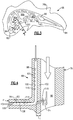
Figure 4 is a cross-sectional view through an airfoil and platform of the vane, illustrating the core and skin passages and flow there through. -
Figure 5 is a schematic cross-sectional view of the vane with a platform cooling exit at a circumferential intrastage gap. -
Figure 6 is a schematic cross-sectional view of the vane with a platform cooling exit at an axial interstage gap. -
Figure 7 is a schematic cross-sectional view of the vane with a platform cooling exit at an axial interstage gap and a circumferential intrastage gap. - The embodiments, examples and alternatives of the preceding paragraphs, the claims, or the following description and drawings, including any of their various aspects or respective individual features, may be taken independently or in any combination. Features described in connection with one embodiment are applicable to all embodiments, unless such features are incompatible.
-
Figure 1 schematically illustrates agas turbine engine 20. Thegas turbine engine 20 is disclosed herein as a two-spool turbofan that generally incorporates afan section 22, acompressor section 24, acombustor section 26 and aturbine section 28. Alternative engines might include an augmenter section (not shown) among other systems or features. Thefan section 22 drives air along a bypass flow path B in a bypass duct defined within a nacelle 15, and also drives air along a core flow path C for compression and communication into thecombustor section 26 then expansion through theturbine section 28. Although depicted as a two-spool turbofan gas turbine engine in the disclosed non-limiting embodiment, it should be understood that the concepts described herein are not limited to use with two-spool turbofans as the teachings may be applied to other types of turbine engines including three-spool architectures. - The
exemplary engine 20 generally includes alow speed spool 30 and ahigh speed spool 32 mounted for rotation about an engine central longitudinal axis X relative to an enginestatic structure 36 viaseveral bearing systems 38. It should be understood that various bearingsystems 38 at various locations may alternatively or additionally be provided, and the location of bearingsystems 38 may be varied as appropriate to the application. - The
low speed spool 30 generally includes aninner shaft 40 that interconnects afan 42, a first (or low)pressure compressor 44 and a first (or low)pressure turbine 46. Theinner shaft 40 is connected to thefan 42 through a speed change mechanism, which in exemplarygas turbine engine 20 is illustrated as a gearedarchitecture 48 to drive thefan 42 at a lower speed than thelow speed spool 30. Thehigh speed spool 32 includes anouter shaft 50 that interconnects a second (or high)pressure compressor 52 and a second (or high)pressure turbine 54. Acombustor 56 is arranged inexemplary gas turbine 20 between thehigh pressure compressor 52 and thehigh pressure turbine 54. Amid-turbine frame 57 of the enginestatic structure 36 is arranged generally between thehigh pressure turbine 54 and thelow pressure turbine 46. Themid-turbine frame 57 furthersupports bearing systems 38 in theturbine section 28. Theinner shaft 40 and theouter shaft 50 are concentric and rotate via bearingsystems 38 about the engine central longitudinal axis X which is collinear with their longitudinal axes. - The core airflow is compressed by the
low pressure compressor 44 then thehigh pressure compressor 52, mixed and burned with fuel in thecombustor 56, then expanded over thehigh pressure turbine 54 andlow pressure turbine 46. Themid-turbine frame 57 includes airfoils 59 which are in the core airflow path C. Theturbines low speed spool 30 andhigh speed spool 32 in response to the expansion. It will be appreciated that each of the positions of thefan section 22,compressor section 24,combustor section 26,turbine section 28, and gearedarchitecture 48 may be varied. For example, gearedarchitecture 48 may be located aft ofcombustor section 26 or even aft ofturbine section 28, andfan section 22 may be positioned forward or aft of the location of gearedarchitecture 48. - The
engine 20 in one example is a high-bypass geared aircraft engine. In a further example, theengine 20 bypass ratio is greater than about six, with an example embodiment being greater than about ten, the gearedarchitecture 48 is an epicyclic gear train, such as a planetary gear system or other gear system, with a gear reduction ratio of greater than about 2.3 and thelow pressure turbine 46 has a pressure ratio that is greater than about five. In one disclosed embodiment, theengine 20 bypass ratio is greater than about ten, the fan diameter is significantly larger than that of thelow pressure compressor 44, and thelow pressure turbine 46 has a pressure ratio that is greater than about five.Low pressure turbine 46 pressure ratio is pressure measured prior to inlet oflow pressure turbine 46 as related to the pressure at the outlet of thelow pressure turbine 46 prior to an exhaust nozzle. The gearedarchitecture 48 may be an epicycle gear train, such as a planetary gear system or other gear system, with a gear reduction ratio of greater than about 2.3:1. It should be understood, however, that the above parameters are only exemplary of one embodiment of a geared architecture engine and that the present invention is applicable to other gas turbine engines including direct drive turbofans. - A significant amount of thrust is provided by the bypass flow B due to the high bypass ratio. The
fan section 22 of theengine 20 is designed for a particular flight condition -- typically cruise at about 0.8 Mach and about 35,000 feet (10,668 meters). The flight condition of 0.8 Mach and 35,000 ft (10,668 meters), with the engine at its best fuel consumption - also known as "bucket cruise Thrust Specific Fuel Consumption ('TSFC')" - is the industry standard parameter of lbm of fuel being burned divided by lbf of thrust the engine produces at that minimum point. "Low fan pressure ratio" is the pressure ratio across the fan blade alone, without a Fan Exit Guide Vane ("FEGV") system. The low fan pressure ratio as disclosed herein according to one non-limiting embodiment is less than about 1.45. "Low corrected fan tip speed" is the actual fan tip speed in ft/sec divided by an industry standard temperature correction of [(Tram °R) / (518.7 °R)]0.5 (where °R = K x 9/5). The "Low corrected fan tip speed" as disclosed herein according to one non-limiting embodiment is less than about 1150 ft / second (350.5 meters/second). - The disclosed cooling configuration is particularly beneficial for turbine vanes of a gas turbine engine where internal cooling of the airfoil is provided and cooling of the vane platforms is desired, although the disclosed arrangement may also be used in the compressor section or for stator vanes. For exemplary purposes, a
turbine vane 68 is described, although the disclosed cooling configuration may be used for blades as well. - Referring to
Figures 2A , stationary androtating stages pressure turbine section 54 are shown. Therotating stage 62 includes an array ofblades 64 terminating in atip 80 that is sealed relative to a bladeouter air seal 66 supported by thestatic structure 36. Thestationary stage 60 has an array ofvanes 68 supported by thestatic structure 36 Eachvane 68 includes at least oneairfoil 78 extending spanwise in a radial direction R between outer andinner platforms airfoil 78 has pressure andsuction sides edges Figure 2B . The pressure andsuction side walls - The
airfoil 78 includes at least one cooling passage provided between the pressure andsuction walls source 92, which is typically provided by a compressor bleed stage. Various cooling configurations may be used. For example, inFigure 3 , leading and trailingedge cooling passages edges passage 90") includes a first ("up")passage 90a near the leadingedge cooling passage 94 that flows into a second ("down")passage 90b, which flows into a third ("up")passage 90c near the trailingedge cooling passage 96. The first, second andthird passages serpentine cooling passage 90 and the leading and trailingedge cooling passages body core passage 90 is shown inFigures 4-6 . Other cooling passage configurations may also be used. The airfoil's mean camber line bisects the core passages in the example shown. - Referring to
Figures 2A and3 , a coolingsource 92, such as bleed air from the compressor section 24 (Fig. 1 ), may be fluidly connected to thecooling passages skin passages 98 to cool theblade 64. The cross-section shown inFigure 3 is more typical of a blade, but a simplified cooling passage may also be used, as is shown inFigures 5-7 , which may be more typical of a vane. - As shown in
Figure 3 and 4 , one or moreskin cooling passages 98 may be provided in the pressure andsuction walls hot side wall 100 and acold side wall 102. Thehot side wall 100 provides the exterior airfoil surface and an outer surface of the airfoilskin cooling passage 98. Thecold side wall 102 provides an inner surface of the airfoilskin cooling passage 98 and a central core cooling passage surface of the central core cooling passage. Film cooling holes 93 may be fluidly connected to the airfoilskin cooling passages 98 to create a thin film boundary layer that protects theairfoil 78 from hot gases in the core flow path C. The airfoilskin cooling passage 98, like the main-bodycore cooling passage 90, receives cooling fluid from the coolingsource 92. - The airfoil
skin cooling passages 98 typically have a much lower aspect ratio H/W, cavity height (H) to cavity width (W), than the "central main-body core" passages. Typically airfoil skin cooling passages have a cavity height (H) to cavity width (W) ratio that may vary in cavity aspect ratio between 3:1 ≥ H/W ≥ 1:5. The height of theskin passage 98, which is generally in the thickness direction and typically normal to a tangent line L at the exterior airfoil surface, is in a range of 0.010-0.200 inches (0.25- 5.08 mm). The skin passage may vary in height and width along its length. - Referring to
Figure 4 , the airfoilskin cooling passage 98 extends to a platformskin cooling passage 108 arranged in the platform, for example, theinner platform 76b. In the example, the airfoilskin cooling passage 98 and the platformskin cooling passage 108 are approximately normal, e.g., 90° +/- 20° relative to one another. The platformskin cooling passage 108 has the same aspect ratio as the airfoilskin cooling passage 98, for example. - Referring to
Figure 5 andFigure 6 , the platform has a perimeter P with axially spaced mate faces 112a and circumferentially spaced mate faces 112b, as shown inFigures 5 and6 . That is, perimeter P is a length or distance that is defined by the platform shape. In this case the perimeter of the platform is made up of circumferential lengths PI along each of the leading edge and the trailing edge. Additionally the perimeter P also comprises of an axial length P2 along each of the pressure side of the platform and the suction side of the platform. The axially spaced mate faces 112a may be arranged adjacent to a static component and/or rotating stage and provide an interstage gap, and the circumferentially spaced mate faces 112b are arranged adjacent to anothervane 68 to provide an intrastage gap. In the example shown inFigure 5 , the platformskin cooling passage 108 terminates in afluid exit 109 arranged at acircumferential mate face 112b. In the example shown inFigure 6 , the platformskin cooling passage 108 terminates influid exit 109 arranged at anaxial mate face 112a. Any number of fluid exits may be used, and thefluid exit 109 may have any suitable exit geometries that may include, but are not limited to, circular, conical, elliptical, oval, or slot shapes that may be of constant cross sectional area, diffused, and/or converged shapes. - Particularly in high pressure turbine vane stages, there is a limited pressure ratio available for cooling. Due to the total length of the airfoil
skin cooling passage 98 and the platform airfoilskin cooling passage 108, there will be significant pressure losses incurred due to the inherently high cooling air flow rate per unit area within the skin core cooling cavities due to the relatively small cross sectional passage area associated with "micro channel" inter-wall design configurations. The airfoil platform airfoilskin cooling passage 108 may include trip strips 115. Trip strips may also be provided in the airfoil skin cooling passage 98 (Figs. 5-7 ). Turbulators, pin fins and/or dimples may also be used in addition to and/or instead of the trip strips. The high internal convective cooling achievable with rib roughened low aspect ratio airfoil skin cooling passages also produces increased frictional losses due to the relative relationship of the trip strip height to the cooling cavity passage height. As a result of the trip strip geometry consuming upwards of 30%-40% of the total skin core cooling cavity channel height, large turbulent vortices are generated. While these flow characteristics are beneficial for generating high internal convective heat transfer, the adverse consequences of increased internal pressure losses are undesirable if film cooling is required to mitigate locally high external heat flux conditions. - Additional bend losses will also be incurred as the cooling airflow is transitioned from a predominately radially oriented airfoil skin cooling passage, to an orthogonally oriented platform airfoil skin cooling passage. The increased thermal efficiency associated with the skin core cavity facilitates the convection of heat from the hot exterior wall to the working fluid. As a result of the excessive cooling air heat pick and pressure loss it becomes difficult to effectively cool the platform regions and mate faces. It therefore becomes necessary to mitigate both the excessive cooling air heat pickup (temperature rise), as well as, restore the internal cooling cavity pressures to ensure positive pressure ratio and minimum back flow margin requirements are maintained across airfoil, airfoil-platform fillet, and platform film cooling holes during engine operation., To address these challenges, the platform airfoil
skin cooling passage 108 is resupplied with cooling fluid from the coolingsource 92 before reaching thefluid exit 109. - Referring to
Figure 4 , thevane 68 includes at least oneresupply hole 110 that fluidly connects the main-bodycore cooling passage 90 and at least one of the airfoilskin cooling passage 98 and the platformskin cooling passage 108. To provide desired pressure and temperature to the platform skin passage, theresupply hole 110 is connected near an intersection, i.e., the bend, between the airfoilskin cooling passage 98 and the platformskin cooling passage 108. Theresupply hole 110 has a ratio of length to hydraulic diameter (L/Dh) in a range of 1-20, and in one example, in a range of 1-10. In the example shown, theresupply hole 110 is arranged at the bend. As a result, internal pressures are maintained and temperatures in the platformskin core passage 108 are reduced to levels capable of achieving the required backside and film cooling effectiveness downstream of the resupply feature. Combining airfoil and platform cooling air with mate face purging may reduce cooling flow requirements to high pressure turbine vanes. This allows for airfoil walls to be less reliant on film cooling, which passes through the airfoil and exhausts on platform and mate faces. - Additive manufacturing and Fugitive Core casting processes allows design flexibility in gas turbine manufacturing. One of the design spaces that additive opens up is in the design of ceramic cores used in the investment casting process. Traditional ceramic cores are made with a core die, which has a finite number of "pull planes." These pull planes restrict the design of ceramic cores to prevent features from overhanging in the direction that the die is pulled when the cores are removed. Additive manufacturing and Fugitive Core processes can remove those manufacturing restrictions, as dies are no longer used to create the ceramic cores.
- An additive manufacturing process may be used to produce an airfoil. Alternatively, a core may be constructed using additive manufacturing and/or Fugitive Core manufacturing may be used to provide the correspondingly cooling passage and cooling hole geometries when casting the airfoil. These advanced manufacturing techniques enable unique core features to be integrally formed as part of the entire ceramic core body and then later cast using conventional loss wax casting processes. Alternatively, powdered metals suitable for aerospace airfoil applications may be used to fabricate airfoil cooling configurations and complex cooling configurations directly. The machine deposits multiple layers of powdered metal onto one another. The layers are joined to one another with reference to CAD data, which relates to a particular cross-section of the airfoil. In one example, the powdered metal may be melted using a direct metal laser sintering process or an electron-beam melting process. With the layers built upon one another and joined to one another cross-section by cross-section, an airfoil with the above-described geometries may be produced, as indicated at. The airfoil may be post-processed to provide desired structural characteristics. For example, the airfoil may be heated to reconfigure the joined layers into a single crystalline structure.
- It should also be understood that although a particular component arrangement is disclosed in the illustrated embodiment, other arrangements will benefit herefrom. Although particular step sequences are shown, described, and claimed, it should be understood that steps may be performed in any order, separated or combined unless otherwise indicated and will still benefit from the embodiments of the present invention.
- Although the different examples have specific components shown in the illustrations, embodiments of this invention are not limited to those particular combinations. It is possible to use some of the components or features from one of the examples in combination with features or components from another one of the examples.
- Although an example embodiment has been disclosed, a worker of ordinary skill in this art would recognize that certain modifications would come within the scope of the claims. For that reason, the following claims should be studied to determine their true scope and content.
Claims (12)
- An airfoil (78) comprising pressure and suction side walls (86,88) extending in a chord-wise direction (C) between leading and trailing edges (82,84) and in a radial direction (R) to provide an exterior airfoil surface, wherein a main-body core cooling passage (90) is arranged between the pressure and suction walls (86,88) in a thickness direction (T) and extends radially toward a platform (76b), a airfoil skin cooling passage (98) is arranged in one of the pressure and suction side walls (86,88) to form a hot side wall (100) and a cold side wall (102), the hot side wall (100) defines a portion of the exterior airfoil surface, the cold side wall (102) defines a portion of the core passage (90), the airfoil skin cooling passage (98) extends to a platform skin cooling passage (108) arranged in the platform (76b), and a resupply hole (110) fluidly connects the main-body core cooling passage (90) and at least one of the airfoil skin cooling passage (98) and the platform skin cooling passage (108).
- The airfoil (78) of claim 1, wherein the platform skin cooling passage (108) terminates at a fluid exit (109) provided at the perimeter (P) of the platform (76b), the perimeter (P) including axial and circumferential mate faces (112a,112b).
- The airfoil (78) of claim 2, wherein the fluid exit (90) is provided on at least one of the axial and circumferential mate faces (112a,112b).
- The airfoil (78) of any preceding claim, wherein at least one of the airfoil skin cooling passage (98) and the platform skin cooling passage (108) includes trip strips (115), turbulators, pin fins and/or dimples.
- The airfoil (78) of any preceding claim, wherein the airfoil skin cooling passage (98) has an aspect ratio that may vary between 3:1 ≥ H/W ≥ 1:5, where H corresponds to a passage height and W corresponds to a passage width, and the passage height (H) is in a range of 0.25- 5.08 mm (0.010-0.200 inches).
- The airfoil (78) of any preceding claim, wherein the platform skin cooling passage (108) has an aspect ratio that may vary between 3:1 ≥ H/W ≥ 1:5, where H corresponds to a passage height and W corresponds to a passage width, and the passage height (H) is in a range of 0.25- 5.08 mm (0.010-0.200 inches).
- The airfoil (78) of any preceding claim, wherein the resupply hole (110) has a ratio of length to hydraulic diameter (L/Dh) in a range of 1-20.
- The airfoil (78) of any preceding claim, wherein the resupply hole (110) is arranged at a bend fluidly connecting the airfoil skin cooling passage (98) and the platform skin cooling passage (108).
- The airfoil (78) of any preceding claim, wherein a film cooling hole (93) extends from the airfoil skin cooling passage (98) to the exterior airfoil surface.
- The airfoil (78) of any preceding claim, wherein the airfoil (78) is a turbine vane (78).
- A gas turbine engine (20) comprising:a combustor section (26) arranged fluidly between a compressor section (24) and a turbine section (28);a stationary stage (60) and a rotating stage (62) arranged in one of the compressor and turbine sections (24,28); andthe airfoil (78) of any of claims 1 to 9 arranged in one of the stationary and rotating stages (60, 62).
- The gas turbine engine (20) of claim 11, wherein the airfoil (78) is a turbine vane (78) arranged in the stationary stage (60) of the turbine section (28).
Applications Claiming Priority (2)
| Application Number | Priority Date | Filing Date | Title |
|---|---|---|---|
| US201862615379P | 2018-01-09 | 2018-01-09 | |
| US15/886,054 US10648343B2 (en) | 2018-01-09 | 2018-02-01 | Double wall turbine gas turbine engine vane platform cooling configuration with main core resupply |
Publications (2)
| Publication Number | Publication Date |
|---|---|
| EP3508697A1 true EP3508697A1 (en) | 2019-07-10 |
| EP3508697B1 EP3508697B1 (en) | 2022-03-16 |
Family
ID=65011932
Family Applications (1)
| Application Number | Title | Priority Date | Filing Date |
|---|---|---|---|
| EP19151057.7A Active EP3508697B1 (en) | 2018-01-09 | 2019-01-09 | Gas turbine engine airfoil-platform cooling configuration with main core resupply |
Country Status (2)
| Country | Link |
|---|---|
| US (1) | US10648343B2 (en) |
| EP (1) | EP3508697B1 (en) |
Cited By (3)
| Publication number | Priority date | Publication date | Assignee | Title |
|---|---|---|---|---|
| WO2022069845A1 (en) * | 2020-10-01 | 2022-04-07 | Safran Aircraft Engines | Turbine blade for an aircraft turbine engine, comprising a platform provided with a channel for primary flow rejection towards a purge cavity |
| FR3114839A1 (en) * | 2020-10-01 | 2022-04-08 | Safran Aircraft Engines | Turbine blade for an aircraft turbomachine, comprising a platform provided with a primary flow rejection channel downstream of the platform |
| WO2022150036A1 (en) * | 2021-01-06 | 2022-07-14 | Siemens Energy Global GmbH & Co. KG | Turbine vane in gas turbine engine |
Families Citing this family (3)
| Publication number | Priority date | Publication date | Assignee | Title |
|---|---|---|---|---|
| JP6806599B2 (en) * | 2017-03-10 | 2021-01-06 | 三菱パワー株式会社 | Turbine blades, turbines and turbine blade cooling methods |
| US10662780B2 (en) * | 2018-01-09 | 2020-05-26 | United Technologies Corporation | Double wall turbine gas turbine engine vane platform cooling configuration with baffle impingement |
| US11162369B1 (en) * | 2020-05-04 | 2021-11-02 | Raytheon Technologies Corporation | Turbine blade cooling hole combination |
Citations (5)
| Publication number | Priority date | Publication date | Assignee | Title |
|---|---|---|---|---|
| EP1882819A1 (en) * | 2006-07-18 | 2008-01-30 | United Technologies Corporation | Integrated platform, tip, and main body microcircuits for turbine blades |
| US20090232660A1 (en) * | 2007-02-15 | 2009-09-17 | Siemens Power Generation, Inc. | Blade for a gas turbine |
| WO2015006026A1 (en) * | 2013-07-12 | 2015-01-15 | United Technologies Corporation | Gas turbine engine component cooling with resupply of cooling passage |
| WO2015053846A2 (en) * | 2013-08-05 | 2015-04-16 | United Technologies Corporation | Engine component having platform with passageway |
| EP3170978A1 (en) * | 2015-11-19 | 2017-05-24 | United Technologies Corporation | Platform, corresponding rotor blade and method of forming |
Family Cites Families (16)
| Publication number | Priority date | Publication date | Assignee | Title |
|---|---|---|---|---|
| US5720431A (en) * | 1988-08-24 | 1998-02-24 | United Technologies Corporation | Cooled blades for a gas turbine engine |
| FR2692318B1 (en) * | 1992-06-11 | 1994-08-19 | Snecma | Fixed blowing of hot gas distribution from a turbo-machine. |
| US5344283A (en) | 1993-01-21 | 1994-09-06 | United Technologies Corporation | Turbine vane having dedicated inner platform cooling |
| DE69503798T2 (en) * | 1994-10-31 | 1999-01-14 | Westinghouse Electric Corp | GAS TURBINE BLADE WITH COOLED BLADE PLATFORM |
| US6254334B1 (en) * | 1999-10-05 | 2001-07-03 | United Technologies Corporation | Method and apparatus for cooling a wall within a gas turbine engine |
| US6454526B1 (en) * | 2000-09-28 | 2002-09-24 | Siemens Westinghouse Power Corporation | Cooled turbine vane with endcaps |
| US7857589B1 (en) * | 2007-09-21 | 2010-12-28 | Florida Turbine Technologies, Inc. | Turbine airfoil with near-wall cooling |
| US8047788B1 (en) * | 2007-10-19 | 2011-11-01 | Florida Turbine Technologies, Inc. | Turbine airfoil with near-wall serpentine cooling |
| US8011881B1 (en) | 2008-01-21 | 2011-09-06 | Florida Turbine Technologies, Inc. | Turbine vane with serpentine cooling |
| US8096772B2 (en) | 2009-03-20 | 2012-01-17 | Siemens Energy, Inc. | Turbine vane for a gas turbine engine having serpentine cooling channels within the inner endwall |
| US8353669B2 (en) | 2009-08-18 | 2013-01-15 | United Technologies Corporation | Turbine vane platform leading edge cooling holes |
| JP5784161B2 (en) * | 2014-01-31 | 2015-09-24 | 株式会社東芝 | Communication system and communication method |
| EP3149284A2 (en) * | 2014-05-29 | 2017-04-05 | General Electric Company | Engine components with impingement cooling features |
| US20170002662A1 (en) * | 2015-07-01 | 2017-01-05 | United Technologies Corporation | Gas turbine engine airfoil with bi-axial skin core |
| US10060269B2 (en) * | 2015-12-21 | 2018-08-28 | General Electric Company | Cooling circuits for a multi-wall blade |
| US10662780B2 (en) * | 2018-01-09 | 2020-05-26 | United Technologies Corporation | Double wall turbine gas turbine engine vane platform cooling configuration with baffle impingement |
-
2018
- 2018-02-01 US US15/886,054 patent/US10648343B2/en active Active
-
2019
- 2019-01-09 EP EP19151057.7A patent/EP3508697B1/en active Active
Patent Citations (5)
| Publication number | Priority date | Publication date | Assignee | Title |
|---|---|---|---|---|
| EP1882819A1 (en) * | 2006-07-18 | 2008-01-30 | United Technologies Corporation | Integrated platform, tip, and main body microcircuits for turbine blades |
| US20090232660A1 (en) * | 2007-02-15 | 2009-09-17 | Siemens Power Generation, Inc. | Blade for a gas turbine |
| WO2015006026A1 (en) * | 2013-07-12 | 2015-01-15 | United Technologies Corporation | Gas turbine engine component cooling with resupply of cooling passage |
| WO2015053846A2 (en) * | 2013-08-05 | 2015-04-16 | United Technologies Corporation | Engine component having platform with passageway |
| EP3170978A1 (en) * | 2015-11-19 | 2017-05-24 | United Technologies Corporation | Platform, corresponding rotor blade and method of forming |
Cited By (4)
| Publication number | Priority date | Publication date | Assignee | Title |
|---|---|---|---|---|
| WO2022069845A1 (en) * | 2020-10-01 | 2022-04-07 | Safran Aircraft Engines | Turbine blade for an aircraft turbine engine, comprising a platform provided with a channel for primary flow rejection towards a purge cavity |
| FR3114838A1 (en) * | 2020-10-01 | 2022-04-08 | Safran Aircraft Engines | Turbine blade for an aircraft turbomachine, comprising a platform provided with a primary flow rejection channel towards a purge cavity |
| FR3114839A1 (en) * | 2020-10-01 | 2022-04-08 | Safran Aircraft Engines | Turbine blade for an aircraft turbomachine, comprising a platform provided with a primary flow rejection channel downstream of the platform |
| WO2022150036A1 (en) * | 2021-01-06 | 2022-07-14 | Siemens Energy Global GmbH & Co. KG | Turbine vane in gas turbine engine |
Also Published As
| Publication number | Publication date |
|---|---|
| US10648343B2 (en) | 2020-05-12 |
| US20190211690A1 (en) | 2019-07-11 |
| EP3508697B1 (en) | 2022-03-16 |
Similar Documents
| Publication | Publication Date | Title |
|---|---|---|
| US11148191B2 (en) | Core arrangement for turbine engine component | |
| EP3508697B1 (en) | Gas turbine engine airfoil-platform cooling configuration with main core resupply | |
| EP3556999B1 (en) | Double wall airfoil cooling configuration for gas turbine engine | |
| EP3508696B1 (en) | Gas turbine engine airfoil-platform cooling configuration | |
| EP3495617B1 (en) | Airfoil with internal cooling passages | |
| EP3105425B1 (en) | Gas turbine engine component cooling circuit with respirating pedestal | |
| EP3498979B1 (en) | Cooled airfoil | |
| US20230203991A1 (en) | Hourglass airfoil cooling configuration | |
| EP3495616B1 (en) | Airfoil with internal cooling passages | |
| EP3495615B1 (en) | Airfoil with internal cooling passages | |
| EP3495618B1 (en) | Airfoil with internal cooling passages | |
| EP3495620B1 (en) | Airfoil with internal cooling passages | |
| EP3495619B1 (en) | Airfoil with internal cooling passages | |
| US20230250725A1 (en) | Cooling arrangement for gas turbine engine component |
Legal Events
| Date | Code | Title | Description |
|---|---|---|---|
| PUAI | Public reference made under article 153(3) epc to a published international application that has entered the european phase |
Free format text: ORIGINAL CODE: 0009012 |
|
| STAA | Information on the status of an ep patent application or granted ep patent |
Free format text: STATUS: THE APPLICATION HAS BEEN PUBLISHED |
|
| AK | Designated contracting states |
Kind code of ref document: A1 Designated state(s): AL AT BE BG CH CY CZ DE DK EE ES FI FR GB GR HR HU IE IS IT LI LT LU LV MC MK MT NL NO PL PT RO RS SE SI SK SM TR |
|
| AX | Request for extension of the european patent |
Extension state: BA ME |
|
| STAA | Information on the status of an ep patent application or granted ep patent |
Free format text: STATUS: REQUEST FOR EXAMINATION WAS MADE |
|
| 17P | Request for examination filed |
Effective date: 20200110 |
|
| RBV | Designated contracting states (corrected) |
Designated state(s): AL AT BE BG CH CY CZ DE DK EE ES FI FR GB GR HR HU IE IS IT LI LT LU LV MC MK MT NL NO PL PT RO RS SE SI SK SM TR |
|
| STAA | Information on the status of an ep patent application or granted ep patent |
Free format text: STATUS: EXAMINATION IS IN PROGRESS |
|
| 17Q | First examination report despatched |
Effective date: 20200511 |
|
| STAA | Information on the status of an ep patent application or granted ep patent |
Free format text: STATUS: EXAMINATION IS IN PROGRESS |
|
| RAP1 | Party data changed (applicant data changed or rights of an application transferred) |
Owner name: RAYTHEON TECHNOLOGIES CORPORATION |
|
| GRAP | Despatch of communication of intention to grant a patent |
Free format text: ORIGINAL CODE: EPIDOSNIGR1 |
|
| STAA | Information on the status of an ep patent application or granted ep patent |
Free format text: STATUS: GRANT OF PATENT IS INTENDED |
|
| INTG | Intention to grant announced |
Effective date: 20210910 |
|
| RIN1 | Information on inventor provided before grant (corrected) |
Inventor name: MONGILLO JR., DOMINIC J. Inventor name: LORICCO, NICHOLAS M. |
|
| GRAS | Grant fee paid |
Free format text: ORIGINAL CODE: EPIDOSNIGR3 |
|
| GRAA | (expected) grant |
Free format text: ORIGINAL CODE: 0009210 |
|
| STAA | Information on the status of an ep patent application or granted ep patent |
Free format text: STATUS: THE PATENT HAS BEEN GRANTED |
|
| AK | Designated contracting states |
Kind code of ref document: B1 Designated state(s): AL AT BE BG CH CY CZ DE DK EE ES FI FR GB GR HR HU IE IS IT LI LT LU LV MC MK MT NL NO PL PT RO RS SE SI SK SM TR |
|
| REG | Reference to a national code |
Ref country code: GB Ref legal event code: FG4D |
|
| REG | Reference to a national code |
Ref country code: CH Ref legal event code: EP |
|
| REG | Reference to a national code |
Ref country code: DE Ref legal event code: R096 Ref document number: 602019012479 Country of ref document: DE |
|
| REG | Reference to a national code |
Ref country code: IE Ref legal event code: FG4D |
|
| REG | Reference to a national code |
Ref country code: AT Ref legal event code: REF Ref document number: 1476014 Country of ref document: AT Kind code of ref document: T Effective date: 20220415 |
|
| REG | Reference to a national code |
Ref country code: LT Ref legal event code: MG9D |
|
| REG | Reference to a national code |
Ref country code: NL Ref legal event code: MP Effective date: 20220316 |
|
| PG25 | Lapsed in a contracting state [announced via postgrant information from national office to epo] |
Ref country code: SE Free format text: LAPSE BECAUSE OF FAILURE TO SUBMIT A TRANSLATION OF THE DESCRIPTION OR TO PAY THE FEE WITHIN THE PRESCRIBED TIME-LIMIT Effective date: 20220316 Ref country code: RS Free format text: LAPSE BECAUSE OF FAILURE TO SUBMIT A TRANSLATION OF THE DESCRIPTION OR TO PAY THE FEE WITHIN THE PRESCRIBED TIME-LIMIT Effective date: 20220316 Ref country code: NO Free format text: LAPSE BECAUSE OF FAILURE TO SUBMIT A TRANSLATION OF THE DESCRIPTION OR TO PAY THE FEE WITHIN THE PRESCRIBED TIME-LIMIT Effective date: 20220616 Ref country code: LT Free format text: LAPSE BECAUSE OF FAILURE TO SUBMIT A TRANSLATION OF THE DESCRIPTION OR TO PAY THE FEE WITHIN THE PRESCRIBED TIME-LIMIT Effective date: 20220316 Ref country code: HR Free format text: LAPSE BECAUSE OF FAILURE TO SUBMIT A TRANSLATION OF THE DESCRIPTION OR TO PAY THE FEE WITHIN THE PRESCRIBED TIME-LIMIT Effective date: 20220316 Ref country code: BG Free format text: LAPSE BECAUSE OF FAILURE TO SUBMIT A TRANSLATION OF THE DESCRIPTION OR TO PAY THE FEE WITHIN THE PRESCRIBED TIME-LIMIT Effective date: 20220616 |
|
| REG | Reference to a national code |
Ref country code: AT Ref legal event code: MK05 Ref document number: 1476014 Country of ref document: AT Kind code of ref document: T Effective date: 20220316 |
|
| PG25 | Lapsed in a contracting state [announced via postgrant information from national office to epo] |
Ref country code: LV Free format text: LAPSE BECAUSE OF FAILURE TO SUBMIT A TRANSLATION OF THE DESCRIPTION OR TO PAY THE FEE WITHIN THE PRESCRIBED TIME-LIMIT Effective date: 20220316 Ref country code: GR Free format text: LAPSE BECAUSE OF FAILURE TO SUBMIT A TRANSLATION OF THE DESCRIPTION OR TO PAY THE FEE WITHIN THE PRESCRIBED TIME-LIMIT Effective date: 20220617 Ref country code: FI Free format text: LAPSE BECAUSE OF FAILURE TO SUBMIT A TRANSLATION OF THE DESCRIPTION OR TO PAY THE FEE WITHIN THE PRESCRIBED TIME-LIMIT Effective date: 20220316 |
|
| PG25 | Lapsed in a contracting state [announced via postgrant information from national office to epo] |
Ref country code: NL Free format text: LAPSE BECAUSE OF FAILURE TO SUBMIT A TRANSLATION OF THE DESCRIPTION OR TO PAY THE FEE WITHIN THE PRESCRIBED TIME-LIMIT Effective date: 20220316 |
|
| PG25 | Lapsed in a contracting state [announced via postgrant information from national office to epo] |
Ref country code: SM Free format text: LAPSE BECAUSE OF FAILURE TO SUBMIT A TRANSLATION OF THE DESCRIPTION OR TO PAY THE FEE WITHIN THE PRESCRIBED TIME-LIMIT Effective date: 20220316 Ref country code: SK Free format text: LAPSE BECAUSE OF FAILURE TO SUBMIT A TRANSLATION OF THE DESCRIPTION OR TO PAY THE FEE WITHIN THE PRESCRIBED TIME-LIMIT Effective date: 20220316 Ref country code: RO Free format text: LAPSE BECAUSE OF FAILURE TO SUBMIT A TRANSLATION OF THE DESCRIPTION OR TO PAY THE FEE WITHIN THE PRESCRIBED TIME-LIMIT Effective date: 20220316 Ref country code: PT Free format text: LAPSE BECAUSE OF FAILURE TO SUBMIT A TRANSLATION OF THE DESCRIPTION OR TO PAY THE FEE WITHIN THE PRESCRIBED TIME-LIMIT Effective date: 20220718 Ref country code: ES Free format text: LAPSE BECAUSE OF FAILURE TO SUBMIT A TRANSLATION OF THE DESCRIPTION OR TO PAY THE FEE WITHIN THE PRESCRIBED TIME-LIMIT Effective date: 20220316 Ref country code: EE Free format text: LAPSE BECAUSE OF FAILURE TO SUBMIT A TRANSLATION OF THE DESCRIPTION OR TO PAY THE FEE WITHIN THE PRESCRIBED TIME-LIMIT Effective date: 20220316 Ref country code: CZ Free format text: LAPSE BECAUSE OF FAILURE TO SUBMIT A TRANSLATION OF THE DESCRIPTION OR TO PAY THE FEE WITHIN THE PRESCRIBED TIME-LIMIT Effective date: 20220316 Ref country code: AT Free format text: LAPSE BECAUSE OF FAILURE TO SUBMIT A TRANSLATION OF THE DESCRIPTION OR TO PAY THE FEE WITHIN THE PRESCRIBED TIME-LIMIT Effective date: 20220316 |
|
| PG25 | Lapsed in a contracting state [announced via postgrant information from national office to epo] |
Ref country code: PL Free format text: LAPSE BECAUSE OF FAILURE TO SUBMIT A TRANSLATION OF THE DESCRIPTION OR TO PAY THE FEE WITHIN THE PRESCRIBED TIME-LIMIT Effective date: 20220316 Ref country code: IS Free format text: LAPSE BECAUSE OF FAILURE TO SUBMIT A TRANSLATION OF THE DESCRIPTION OR TO PAY THE FEE WITHIN THE PRESCRIBED TIME-LIMIT Effective date: 20220716 Ref country code: AL Free format text: LAPSE BECAUSE OF FAILURE TO SUBMIT A TRANSLATION OF THE DESCRIPTION OR TO PAY THE FEE WITHIN THE PRESCRIBED TIME-LIMIT Effective date: 20220316 |
|
| REG | Reference to a national code |
Ref country code: DE Ref legal event code: R097 Ref document number: 602019012479 Country of ref document: DE |
|
| PLBE | No opposition filed within time limit |
Free format text: ORIGINAL CODE: 0009261 |
|
| STAA | Information on the status of an ep patent application or granted ep patent |
Free format text: STATUS: NO OPPOSITION FILED WITHIN TIME LIMIT |
|
| PG25 | Lapsed in a contracting state [announced via postgrant information from national office to epo] |
Ref country code: DK Free format text: LAPSE BECAUSE OF FAILURE TO SUBMIT A TRANSLATION OF THE DESCRIPTION OR TO PAY THE FEE WITHIN THE PRESCRIBED TIME-LIMIT Effective date: 20220316 |
|
| 26N | No opposition filed |
Effective date: 20221219 |
|
| PG25 | Lapsed in a contracting state [announced via postgrant information from national office to epo] |
Ref country code: SI Free format text: LAPSE BECAUSE OF FAILURE TO SUBMIT A TRANSLATION OF THE DESCRIPTION OR TO PAY THE FEE WITHIN THE PRESCRIBED TIME-LIMIT Effective date: 20220316 |
|
| PGFP | Annual fee paid to national office [announced via postgrant information from national office to epo] |
Ref country code: DE Payment date: 20221220 Year of fee payment: 5 |
|
| P01 | Opt-out of the competence of the unified patent court (upc) registered |
Effective date: 20230521 |
|
| PG25 | Lapsed in a contracting state [announced via postgrant information from national office to epo] |
Ref country code: IT Free format text: LAPSE BECAUSE OF FAILURE TO SUBMIT A TRANSLATION OF THE DESCRIPTION OR TO PAY THE FEE WITHIN THE PRESCRIBED TIME-LIMIT Effective date: 20220316 |
|
| REG | Reference to a national code |
Ref country code: CH Ref legal event code: PL |
|
| PG25 | Lapsed in a contracting state [announced via postgrant information from national office to epo] |
Ref country code: LU Free format text: LAPSE BECAUSE OF NON-PAYMENT OF DUE FEES Effective date: 20230109 |
|
| REG | Reference to a national code |
Ref country code: BE Ref legal event code: MM Effective date: 20230131 |
|
| PG25 | Lapsed in a contracting state [announced via postgrant information from national office to epo] |
Ref country code: LI Free format text: LAPSE BECAUSE OF NON-PAYMENT OF DUE FEES Effective date: 20230131 Ref country code: CH Free format text: LAPSE BECAUSE OF NON-PAYMENT OF DUE FEES Effective date: 20230131 |
|
| PG25 | Lapsed in a contracting state [announced via postgrant information from national office to epo] |
Ref country code: BE Free format text: LAPSE BECAUSE OF NON-PAYMENT OF DUE FEES Effective date: 20230131 |
|
| PGFP | Annual fee paid to national office [announced via postgrant information from national office to epo] |
Ref country code: GB Payment date: 20231219 Year of fee payment: 6 |
|
| PG25 | Lapsed in a contracting state [announced via postgrant information from national office to epo] |
Ref country code: IE Free format text: LAPSE BECAUSE OF NON-PAYMENT OF DUE FEES Effective date: 20230109 |
|
| PGFP | Annual fee paid to national office [announced via postgrant information from national office to epo] |
Ref country code: FR Payment date: 20231219 Year of fee payment: 6 |