EP3508360A1 - Tubeless valve assembly - Google Patents
Tubeless valve assembly Download PDFInfo
- Publication number
- EP3508360A1 EP3508360A1 EP18213595.4A EP18213595A EP3508360A1 EP 3508360 A1 EP3508360 A1 EP 3508360A1 EP 18213595 A EP18213595 A EP 18213595A EP 3508360 A1 EP3508360 A1 EP 3508360A1
- Authority
- EP
- European Patent Office
- Prior art keywords
- securing feature
- rim
- valve stem
- bicycle rim
- opening
- Prior art date
- Legal status (The legal status is an assumption and is not a legal conclusion. Google has not performed a legal analysis and makes no representation as to the accuracy of the status listed.)
- Granted
Links
Images


Classifications
-
- B—PERFORMING OPERATIONS; TRANSPORTING
- B60—VEHICLES IN GENERAL
- B60C—VEHICLE TYRES; TYRE INFLATION; TYRE CHANGING; CONNECTING VALVES TO INFLATABLE ELASTIC BODIES IN GENERAL; DEVICES OR ARRANGEMENTS RELATED TO TYRES
- B60C29/00—Arrangements of tyre-inflating valves to tyres or rims; Accessories for tyre-inflating valves, not otherwise provided for
- B60C29/02—Connection to rims
-
- B—PERFORMING OPERATIONS; TRANSPORTING
- B60—VEHICLES IN GENERAL
- B60B—VEHICLE WHEELS; CASTORS; AXLES FOR WHEELS OR CASTORS; INCREASING WHEEL ADHESION
- B60B21/00—Rims
- B60B21/02—Rims characterised by transverse section
- B60B21/025—Rims characterised by transverse section the transverse section being hollow
-
- B—PERFORMING OPERATIONS; TRANSPORTING
- B60—VEHICLES IN GENERAL
- B60B—VEHICLE WHEELS; CASTORS; AXLES FOR WHEELS OR CASTORS; INCREASING WHEEL ADHESION
- B60B21/00—Rims
- B60B21/10—Rims characterised by the form of tyre-seat or flange, e.g. corrugated
-
- B—PERFORMING OPERATIONS; TRANSPORTING
- B60—VEHICLES IN GENERAL
- B60B—VEHICLE WHEELS; CASTORS; AXLES FOR WHEELS OR CASTORS; INCREASING WHEEL ADHESION
- B60B21/00—Rims
- B60B21/12—Appurtenances, e.g. lining bands
-
- B—PERFORMING OPERATIONS; TRANSPORTING
- B60—VEHICLES IN GENERAL
- B60B—VEHICLE WHEELS; CASTORS; AXLES FOR WHEELS OR CASTORS; INCREASING WHEEL ADHESION
- B60B27/00—Hubs
- B60B27/02—Hubs adapted to be rotatably arranged on axle
- B60B27/023—Hubs adapted to be rotatably arranged on axle specially adapted for bicycles
-
- B—PERFORMING OPERATIONS; TRANSPORTING
- B60—VEHICLES IN GENERAL
- B60C—VEHICLE TYRES; TYRE INFLATION; TYRE CHANGING; CONNECTING VALVES TO INFLATABLE ELASTIC BODIES IN GENERAL; DEVICES OR ARRANGEMENTS RELATED TO TYRES
- B60C29/00—Arrangements of tyre-inflating valves to tyres or rims; Accessories for tyre-inflating valves, not otherwise provided for
- B60C29/005—Arrangements of tyre-inflating valves to tyres or rims; Accessories for tyre-inflating valves, not otherwise provided for characterised by particular features of the valve stem
-
- F—MECHANICAL ENGINEERING; LIGHTING; HEATING; WEAPONS; BLASTING
- F16—ENGINEERING ELEMENTS AND UNITS; GENERAL MEASURES FOR PRODUCING AND MAINTAINING EFFECTIVE FUNCTIONING OF MACHINES OR INSTALLATIONS; THERMAL INSULATION IN GENERAL
- F16K—VALVES; TAPS; COCKS; ACTUATING-FLOATS; DEVICES FOR VENTING OR AERATING
- F16K27/00—Construction of housing; Use of materials therefor
- F16K27/02—Construction of housing; Use of materials therefor of lift valves
- F16K27/0209—Check valves or pivoted valves
-
- B—PERFORMING OPERATIONS; TRANSPORTING
- B60—VEHICLES IN GENERAL
- B60B—VEHICLE WHEELS; CASTORS; AXLES FOR WHEELS OR CASTORS; INCREASING WHEEL ADHESION
- B60B1/00—Spoked wheels; Spokes thereof
- B60B1/003—Spoked wheels; Spokes thereof specially adapted for bicycles
-
- B—PERFORMING OPERATIONS; TRANSPORTING
- B60—VEHICLES IN GENERAL
- B60B—VEHICLE WHEELS; CASTORS; AXLES FOR WHEELS OR CASTORS; INCREASING WHEEL ADHESION
- B60B2310/00—Manufacturing methods
- B60B2310/30—Manufacturing methods joining
- B60B2310/305—Manufacturing methods joining by screwing
-
- B—PERFORMING OPERATIONS; TRANSPORTING
- B60—VEHICLES IN GENERAL
- B60B—VEHICLE WHEELS; CASTORS; AXLES FOR WHEELS OR CASTORS; INCREASING WHEEL ADHESION
- B60B2360/00—Materials; Physical forms thereof
- B60B2360/30—Synthetic materials
-
- B—PERFORMING OPERATIONS; TRANSPORTING
- B60—VEHICLES IN GENERAL
- B60B—VEHICLE WHEELS; CASTORS; AXLES FOR WHEELS OR CASTORS; INCREASING WHEEL ADHESION
- B60B2900/00—Purpose of invention
- B60B2900/50—Improvement of
- B60B2900/511—Sealing
- B60B2900/5118—Sealing against oil-loss
Definitions
- the present invention relates generally to the field of bicycle wheels and specifically to valve assemblies adapted primarily for use with tubeless tires.
- Bicycle wheels commonly include an axle, a hub rotatable on the axle, spokes extending radially from the hub, a rim supported by the spokes, and a tire. Some wheels also include a pneumatic tube positioned inside the tire to facilitate inflation of the tire, while other wheels are "tubeless.”
- Tubeless wheels commonly include a hole in the rim and a valve assembly that is inserted through the hole in a radially inward direction from an interior of the rim (where the tire will be mounted) to an exterior of the rim (usually radially inward of the rim).
- the valve assembly typically includes an enlarged resilient portion on its radially outer end designed to seal against the rim around the hole on the interior of the rim.
- the radially inner end of the valve assembly is threaded to facilitate threading on a knurled nut, after the valve assembly is positioned in the hole in the rim, to secure the valve assembly onto the rim.
- the present invention provides a bicycle wheel comprising an axle, a hub mounted for rotation on the axle, a rim mounted for rotation with the hub, and a valve assembly.
- the rim includes a radially inner wall having an inner opening and a radially outer wall having an outer opening.
- a first portion of the rim (e.g., defining the inner opening or the outer opening, and preferably the outer opening) includes a first securing feature.
- the valve assembly is positioned in the inner opening and outer opening, and the valve assembly includes a second securing feature engaging the first securing feature to releasably secure the valve assembly to the rim.
- the first securing feature comprises inner threads in the first portion of the rim
- the second securing feature comprises outer threads on the valve assembly, the outer threads being threaded into the inner threads.
- the rim can include a separate plate that defines the first engaging feature.
- the valve assembly includes a valve stem and a resilient bumper (e.g., an annular member) coupled to (e.g., wrapped around) the valve stem.
- the resilient bumper is aligned with a second portion of the rim defining either the inner opening or the outer opening (preferably the inner opening).
- the valve assembly can further include a seal member compressed between the valve stem and the rim (e.g., positioned substantially adjacent the first and second securing features).
- the seal member is positioned in an annular groove in an underside of an enlarged head of the valve stem.
- the apparatus can comprise a bicycle wheel.
- the bicycle wheel can comprise an axle, a hub mounted for rotation on the axle, a rim mounted for rotation with the hub, the rim including a radially inner wall having an inner opening and a radially outer wall having an outer opening, wherein a first portion of the rim, defining one of the inner opening or the outer opening, includes a first securing feature; and a valve assembly positioned in the inner opening and the outer opening, the valve assembly including a second securing feature engaging the first securing feature to releasably secure the valve assembly to the rim.
- the apparatus further can comprise a bicycle having the bicycle wheel.
- first securing feature can comprise inner threads in the first portion of the rim
- second securing feature can comprise outer threads on the valve assembly, the outer threads being threaded into the inner threads
- valve assembly can include a valve stem, and a resilient bumper coupled to the valve stem and aligned with a second portion of the rim defining an other one of the inner opening or the outer opening.
- the second portion of the rim can define the inner opening.
- the resilient bumper can comprise an annular member wrapped around the valve stem. Further, in these or other embodiments,
- the first securing feature can comprise a quarter-turn receptacle
- the second securing feature can comprise a quarter-turn post adapted to fit in the quarter-turn receptacle.
- the rim can include a plate defining the first securing feature.
- the bicycle rim assembly can comprise a rim including a radially inner wall having an inner opening and a radially outer wall having an outer opening, wherein a first portion of the rim defining one of the inner opening or the outer opening includes a first securing feature, and a valve assembly positioned in the inner opening and the outer opening, the valve assembly including a second securing feature engaging the first securing feature to releasably secure the valve assembly to the rim.
- the first portion of the rim can define the outer opening.
- first securing feature can comprise inner threads in the first portion of the rim
- second securing feature can comprise outer threads on the valve assembly, the outer threads being threaded into the inner threads
- valve assembly further can include a valve stem and a resilient bumper coupled to the valve stem and aligned with a second portion of the rim defining an other one of the inner opening or the outer opening.
- the second portion of the rim defines the inner opening.
- the resilient bumper can comprise an annular member wrapped around the valve stem.
- the first securing feature can comprise a quarter-turn receptacle
- the second securing feature can comprise a quarter-turn post adapted to fit in the quarter-turn receptacle.
- the rim can include a plate defining the first securing feature.
- Some embodiments include a valve assembly.
- the valve assembly can be adapted to be positioned in an opening in a bicycle rim, the opening having a first securing feature.
- the valve assembly can comprise a valve stem and a valve positioned in the valve stem and movable between an open position and a closed position, the valve stem including a second securing feature adapted to releasably engage the first securing feature to releasably secure the valve stem to the bicycle rim.
- the first securing feature on the rim can comprise inner threads and the second securing feature can comprise outer threads on the valve stem, the outer threads being threadable into the inner threads.
- the first securing feature on the rim can comprise a quarter-turn receptacle and the second securing feature can comprise a quarter-turn post releasably insertable into the quarter-turn receptacle.
- valve assembly further can include a resilient bumper coupled to the valve stem spaced from the second securing feature.
- Fig. 1 shows a bicycle 10 that includes a front wheel 12, a rear wheel 14, and a frame 16.
- the front wheel 12 includes an axle 18, a hub 20 rotationally supported on the axle 18, spokes 22 extending radially from the hub 20, a rim assembly 24 secured to the end of the spokes 22, and a tire 26 supported on the rim assembly 24.
- the frame 16 has a head tube 28, a front fork 30 rotationally supported by the head tube 28, a top tube 32 connected to and extending rearward from the head tube 28, and a down tube 34 connected to the head tube 28 below the top tube 32 and extending generally downward toward a bottom bracket (not shown) of the frame 16.
- a seat tube 36 extends upward from the bottom bracket and is connected to the top tube 32, and a seat 38 is supported by the seat tube 36.
- the bicycle also includes a handlebar 40 for turning the front wheel 12 via the front fork 30.
- Figs. 2-4 illustrate the rim assembly 24 of the front wheel of Fig. 1 , and the rear wheel has a substantially similar rim assembly.
- the rim assembly 24 includes a rim 42 and a valve assembly 44.
- the illustrated rim 42 includes a radially inner wall 46 engaging the spokes 22 and a radially outer wall 48 supporting the tire 26.
- the radially inner wall 46 includes an inner opening 50 ( Fig. 4 ) designed to receive the valve assembly 44, as described below in more detail.
- the radially outer wall 48 including an aperture 54 defined by a recessed lip 56.
- the outer wall 48 further includes a threaded insert 58 comprising a thin plate 60 that is sized to rest on the recessed lip 56 in the aperture 54 such that an upper surface 62 of the threaded insert 58 is recessed below the adjacent surface of the radially outer wall 48.
- the threaded insert 58 is preferably secured to the rest of the outer wall 48, such as with adhesive or fasteners.
- the threaded insert 58 includes a first securing feature in the form of an outer opening 64 having inner threads, the function of which is described below in more detail.
- the threaded insert 58 is made of plastic, composite, or a metallic material, such as titanium, aluminum, or steel.
- the threaded insert 58 is shown as a separate part, it should be understood that it could instead be formed integrally with the rest of the outer wall, as described below in connection with the embodiment of Fig. 5 .
- the valve assembly 44 includes a valve stem 66 comprising a cylindrical body 68 and a plunger valve 70 positioned in the cylindrical body 68, as is generally known in the art to facilitate one-way inflation of the tire.
- the valve stem 66 further includes an enlarged head 72 on a radially outer end of the cylindrical body 68.
- the valve stem 66 further includes a second securing feature in the form of outer threads 74 on an exterior surface of the cylindrical body 68 adjacent the enlarged head 72.
- the outer threads 74 are designed to thread into the outer opening 64 to releasably secure the valve assembly 44 to the rim 42.
- the illustrated valve assembly 44 further includes a seal member in the form of an O-ring 76 compressed between the valve stem 66 and the rim 42.
- the O-ring 76 is positioned in a first annular groove 78 in the underside of the enlarged head 72 of the valve stem 66.
- the first annular groove 78 can be omitted and the O-ring 76 can be compressed against a flat bottom of the head 72.
- the illustrated O-ring 76 is made of a synthetic rubber such as Buna-N, natural rubber, or silicone in the hardness range of 40-100 Shore A.
- the illustrated valve assembly 44 further includes a second annular groove 80 in an outer surface of the cylindrical body 68 and a resilient bumper 82 positioned in the second annular groove 80 to couple the resilient bumper 82 to the valve stem 66.
- the second annular groove 80 and resilient bumper 82 are aligned with the radially inner wall 46 of the rim 42 such that the resilient bumper 82 is positioned in the inner opening 50, which provides a cushioned connection between the valve stem 66 and the inner wall 46 of the rim 42. This cushioned connection reduces audible rattling that might occur as a result of intermittent contact between the valve stem 66 and the inner wall 46 of the rim 42.
- the second annular groove 80 can be omitted and the bumper 82 can be secured to a flat cylindrical outer surface of the cylindrical body 68.
- the bumper can held in place on the cylindrical body 68 by placement in the second annular groove 80, by friction, bonding, co-molding, vulcanization, any combination of these, or any suitable technique.
- the illustrated bumper 82 is made of a soft plastic, synthetic rubber such as Buna N, natural rubber, or Silicon in the hardness range of 40-100 Shore A.
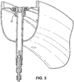
- Fig. 5 illustrates an alternative embodiment of the present invention in which the threaded outer opening is formed integrally with the outer wall of the rim.
- the threaded outer opening of this embodiment is formed in an aluminum rim by a flow drilling process that creates an integral cylindrical chimney 90 that is subsequently tapped with a thread rolling tap to create the threaded outer opening.
- the threaded outer opening can be formed by any appropriate operation, such as by drilling a hole and securing a blind threaded fastener like a rivet nut.
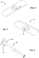
- first and second securing features can be embodied in securing mechanisms other than a threaded attachment,
- the first securing feature is provided by a quarter-turn, cam-type receptacle 92 formed in an insert 94
- the second securing feature is provided by a valve body incorporating a quarter-turn post 96 having tabs 98.
- the tabs 98 fit into slots in the receptacle 92, and the post 96 can be turned, resulting in sliding of the tabs 98 against cam surfaces on the underside of the receptacle 92 to releasably lock the valve body into the insert 94.
Landscapes
- Engineering & Computer Science (AREA)
- Mechanical Engineering (AREA)
- General Engineering & Computer Science (AREA)
- Check Valves (AREA)
Abstract
Description
- This application claims priority to
U.S. Application No. 15/863,599, filed January 5,2018 - The present invention relates generally to the field of bicycle wheels and specifically to valve assemblies adapted primarily for use with tubeless tires.
- Bicycle wheels commonly include an axle, a hub rotatable on the axle, spokes extending radially from the hub, a rim supported by the spokes, and a tire. Some wheels also include a pneumatic tube positioned inside the tire to facilitate inflation of the tire, while other wheels are "tubeless."
- Tubeless wheels commonly include a hole in the rim and a valve assembly that is inserted through the hole in a radially inward direction from an interior of the rim (where the tire will be mounted) to an exterior of the rim (usually radially inward of the rim). The valve assembly typically includes an enlarged resilient portion on its radially outer end designed to seal against the rim around the hole on the interior of the rim. The radially inner end of the valve assembly is threaded to facilitate threading on a knurled nut, after the valve assembly is positioned in the hole in the rim, to secure the valve assembly onto the rim.
-
-
Fig. 1 is a side view of a bicycle including wheels embodying the invention. -
Fig. 2 is a perspective view of a rim assembly from one of the wheels shown inFig. 1 . -
Fig. 3 is an exploded perspective view of a portion of the rim assembly ofFig. 2 including a rim, a threaded insert, and a valve assembly. -
Fig. 4 is a section view taken along line 4-4 inFig. 2 . -
Fig. 5 of a section view of an alternate embodiment with the threaded insert removed. -
Fig. 6 is a top perspective view of an insert corresponding with a second embodiment of the invention. -
Fig. 7 is bottom perspective view of the insert ofFig. 6 . -
Fig. 8 is a perspective view of a valve body corresponding with the second embodiment of the invention. - The present invention provides a bicycle wheel comprising an axle, a hub mounted for rotation on the axle, a rim mounted for rotation with the hub, and a valve assembly. The rim includes a radially inner wall having an inner opening and a radially outer wall having an outer opening. A first portion of the rim (e.g., defining the inner opening or the outer opening, and preferably the outer opening) includes a first securing feature. The valve assembly is positioned in the inner opening and outer opening, and the valve assembly includes a second securing feature engaging the first securing feature to releasably secure the valve assembly to the rim. Preferably, the first securing feature comprises inner threads in the first portion of the rim, and the second securing feature comprises outer threads on the valve assembly, the outer threads being threaded into the inner threads. The rim can include a separate plate that defines the first engaging feature.
- In one embodiment, the valve assembly includes a valve stem and a resilient bumper (e.g., an annular member) coupled to (e.g., wrapped around) the valve stem. The resilient bumper is aligned with a second portion of the rim defining either the inner opening or the outer opening (preferably the inner opening).
- The valve assembly can further include a seal member compressed between the valve stem and the rim (e.g., positioned substantially adjacent the first and second securing features). Preferably, the seal member is positioned in an annular groove in an underside of an enlarged head of the valve stem.
- Some embodiments include an apparatus. The apparatus can comprise a bicycle wheel. The bicycle wheel can comprise an axle, a hub mounted for rotation on the axle, a rim mounted for rotation with the hub, the rim including a radially inner wall having an inner opening and a radially outer wall having an outer opening, wherein a first portion of the rim, defining one of the inner opening or the outer opening, includes a first securing feature; and a valve assembly positioned in the inner opening and the outer opening, the valve assembly including a second securing feature engaging the first securing feature to releasably secure the valve assembly to the rim.
- In these or other embodiments, the apparatus further can comprise a bicycle having the bicycle wheel.
- Further, in these or other embodiments, the first securing feature can comprise inner threads in the first portion of the rim, and the second securing feature can comprise outer threads on the valve assembly, the outer threads being threaded into the inner threads.
- Further, in these or other embodiments, the valve assembly can include a valve stem, and a resilient bumper coupled to the valve stem and aligned with a second portion of the rim defining an other one of the inner opening or the outer opening.
- Further, in these or other embodiments, the second portion of the rim can define the inner opening.
- Further, in these or other embodiments, the resilient bumper can comprise an annular member wrapped around the valve stem. Further, in these or other embodiments,
- Further, in these or other embodiments, the first securing feature can comprise a quarter-turn receptacle, and the second securing feature can comprise a quarter-turn post adapted to fit in the quarter-turn receptacle.
- Further, in these or other embodiments, the rim can include a plate defining the first securing feature.
- Some embodiments include a bicycle rim assembly. The bicycle rim assembly can comprise a rim including a radially inner wall having an inner opening and a radially outer wall having an outer opening, wherein a first portion of the rim defining one of the inner opening or the outer opening includes a first securing feature, and a valve assembly positioned in the inner opening and the outer opening, the valve assembly including a second securing feature engaging the first securing feature to releasably secure the valve assembly to the rim.
- In these or other embodiments, the first portion of the rim can define the outer opening.
- Further, in these or other embodiments, the first securing feature can comprise inner threads in the first portion of the rim, and the second securing feature can comprise outer threads on the valve assembly, the outer threads being threaded into the inner threads.
- Further, in these or other embodiments, the valve assembly further can include a valve stem and a resilient bumper coupled to the valve stem and aligned with a second portion of the rim defining an other one of the inner opening or the outer opening.
- Further, in these or other embodiments, the second portion of the rim defines the inner opening.
- Further, in these or other embodiments, the resilient bumper can comprise an annular member wrapped around the valve stem.
- Further, in these or other embodiments, the first securing feature can comprise a quarter-turn receptacle, and the second securing feature can comprise a quarter-turn post adapted to fit in the quarter-turn receptacle.
- Further, in these or other embodiments, the rim can include a plate defining the first securing feature.
- Some embodiments include a valve assembly. The valve assembly can be adapted to be positioned in an opening in a bicycle rim, the opening having a first securing feature. The valve assembly can comprise a valve stem and a valve positioned in the valve stem and movable between an open position and a closed position, the valve stem including a second securing feature adapted to releasably engage the first securing feature to releasably secure the valve stem to the bicycle rim.
- In these or other embodiments, the first securing feature on the rim can comprise inner threads and the second securing feature can comprise outer threads on the valve stem, the outer threads being threadable into the inner threads.
- Further, in these or other embodiments, the first securing feature on the rim can comprise a quarter-turn receptacle and the second securing feature can comprise a quarter-turn post releasably insertable into the quarter-turn receptacle.
- Further, in these or other embodiments, the valve assembly further can include a resilient bumper coupled to the valve stem spaced from the second securing feature.
- Other elements of the invention will become apparent by consideration of the detailed description and drawings.
- Before any embodiments of the invention are explained in detail, it is to be understood that the invention is not limited in its application to the details of construction and the arrangement of components set forth in the following description or illustrated in the following drawings. The invention is capable of other embodiments and of being practiced or of being carried out in various ways.
-
Fig. 1 shows abicycle 10 that includes afront wheel 12, arear wheel 14, and aframe 16. Thefront wheel 12 includes anaxle 18, ahub 20 rotationally supported on theaxle 18,spokes 22 extending radially from thehub 20, arim assembly 24 secured to the end of thespokes 22, and atire 26 supported on therim assembly 24. Theframe 16 has ahead tube 28, afront fork 30 rotationally supported by thehead tube 28, atop tube 32 connected to and extending rearward from thehead tube 28, and adown tube 34 connected to thehead tube 28 below thetop tube 32 and extending generally downward toward a bottom bracket (not shown) of theframe 16. Aseat tube 36 extends upward from the bottom bracket and is connected to thetop tube 32, and aseat 38 is supported by theseat tube 36. The bicycle also includes ahandlebar 40 for turning thefront wheel 12 via thefront fork 30. -
Figs. 2-4 illustrate therim assembly 24 of the front wheel ofFig. 1 , and the rear wheel has a substantially similar rim assembly. Therim assembly 24 includes arim 42 and avalve assembly 44. The illustratedrim 42 includes a radiallyinner wall 46 engaging thespokes 22 and a radiallyouter wall 48 supporting thetire 26. The radiallyinner wall 46 includes an inner opening 50 (Fig. 4 ) designed to receive thevalve assembly 44, as described below in more detail. The radiallyouter wall 48 including anaperture 54 defined by a recessedlip 56. - The
outer wall 48 further includes a threadedinsert 58 comprising athin plate 60 that is sized to rest on the recessedlip 56 in theaperture 54 such that anupper surface 62 of the threadedinsert 58 is recessed below the adjacent surface of the radiallyouter wall 48. The threadedinsert 58 is preferably secured to the rest of theouter wall 48, such as with adhesive or fasteners. The threadedinsert 58 includes a first securing feature in the form of anouter opening 64 having inner threads, the function of which is described below in more detail. In the illustrated embodiment, the threadedinsert 58 is made of plastic, composite, or a metallic material, such as titanium, aluminum, or steel. Although the threadedinsert 58 is shown as a separate part, it should be understood that it could instead be formed integrally with the rest of the outer wall, as described below in connection with the embodiment ofFig. 5 . - The
valve assembly 44 includes avalve stem 66 comprising acylindrical body 68 and aplunger valve 70 positioned in thecylindrical body 68, as is generally known in the art to facilitate one-way inflation of the tire. The valve stem 66 further includes anenlarged head 72 on a radially outer end of thecylindrical body 68. The valve stem 66 further includes a second securing feature in the form ofouter threads 74 on an exterior surface of thecylindrical body 68 adjacent theenlarged head 72. Theouter threads 74 are designed to thread into theouter opening 64 to releasably secure thevalve assembly 44 to therim 42. - The illustrated
valve assembly 44 further includes a seal member in the form of an O-ring 76 compressed between thevalve stem 66 and therim 42. The O-ring 76 is positioned in a firstannular groove 78 in the underside of theenlarged head 72 of thevalve stem 66. Alternatively, the firstannular groove 78 can be omitted and the O-ring 76 can be compressed against a flat bottom of thehead 72. The illustrated O-ring 76 is made of a synthetic rubber such as Buna-N, natural rubber, or silicone in the hardness range of 40-100 Shore A. - The illustrated
valve assembly 44 further includes a secondannular groove 80 in an outer surface of thecylindrical body 68 and aresilient bumper 82 positioned in the secondannular groove 80 to couple theresilient bumper 82 to thevalve stem 66. As shown inFig. 4 , the secondannular groove 80 andresilient bumper 82 are aligned with the radiallyinner wall 46 of therim 42 such that theresilient bumper 82 is positioned in theinner opening 50, which provides a cushioned connection between thevalve stem 66 and theinner wall 46 of therim 42. This cushioned connection reduces audible rattling that might occur as a result of intermittent contact between thevalve stem 66 and theinner wall 46 of therim 42. Alternatively, the secondannular groove 80 can be omitted and thebumper 82 can be secured to a flat cylindrical outer surface of thecylindrical body 68. The bumper can held in place on thecylindrical body 68 by placement in the secondannular groove 80, by friction, bonding, co-molding, vulcanization, any combination of these, or any suitable technique. The illustratedbumper 82 is made of a soft plastic, synthetic rubber such as Buna N, natural rubber, or Silicon in the hardness range of 40-100 Shore A. -
Fig. 5 illustrates an alternative embodiment of the present invention in which the threaded outer opening is formed integrally with the outer wall of the rim. Specifically, the threaded outer opening of this embodiment is formed in an aluminum rim by a flow drilling process that creates an integralcylindrical chimney 90 that is subsequently tapped with a thread rolling tap to create the threaded outer opening. Alternatively, the threaded outer opening can be formed by any appropriate operation, such as by drilling a hole and securing a blind threaded fastener like a rivet nut. - It should be understood that the first and second securing features can be embodied in securing mechanisms other than a threaded attachment, For example, in an alternative embodiment illustrated in
figs. 6-8 , the first securing feature is provided by a quarter-turn, cam-type receptacle 92 formed in aninsert 94, and the second securing feature is provided by a valve body incorporating a quarter-turn post 96 havingtabs 98. Thetabs 98 fit into slots in thereceptacle 92, and thepost 96 can be turned, resulting in sliding of thetabs 98 against cam surfaces on the underside of thereceptacle 92 to releasably lock the valve body into theinsert 94. - Various features of the invention are set forth in the following claims.
- When used in this specification and claims, the terms "comprises" and "comprising" and variations thereof mean that the specified features, steps or integers are included. The terms are not to be interpreted to exclude the presence of other features, steps or features.
- The features disclosed in the foregoing description, or the following claims, or the accompanying drawings, expressed in their specific forms or in terms of a means for performing the disclosed function, or a method or process for attaining the disclosed result, as appropriate, may, separately, or in any combination of such features, be utilised for realising the invention in diverse forms thereof.
Claims (15)
- An apparatus comprising:a valve assembly adapted to be positioned in an inner opening and an outer opening of a bicycle rim, wherein the bicycle rim includes a radially inner wall having the inner opening and a radially outer wall having the outer opening, wherein a first portion of the bicycle rim defining one of the inner opening or the outer opening includes a first securing feature, and wherein the valve assembly comprises:a valve stem; anda valve positioned in the valve stem and movable between an open position and a closed position, the valve stem including a second securing feature adapted to releasably engage the first securing feature to releasably secure the valve stem to the bicycle rim.
- The apparatus of claim 1, further comprising:the bicycle rim.
- The apparatus of claim 2, further comprising:a bicycle having the bicycle rim.
- The apparatus of any one of claims 1-3, wherein the first portion of the bicycle rim defines the outer opening.
- The apparatus of any one of claims 1-4, wherein the valve assembly further includes:a resilient bumper coupled to the valve stem and aligned with a second portion of the rim defining an other one of the inner opening or the outer opening.
- The apparatus of claim 5, wherein the second portion of the bicycle rim defines the inner opening.
- The apparatus of claim 6, wherein the resilient bumper comprises an annular member wrapped around the valve stem.
- The apparatus of any one of claims 5-7, wherein the valve stem includes an annular groove configured to receive the resilient bumper.
- The apparatus of any one of claims 1-8, wherein the first securing feature comprises inner threads in the first portion of the bicycle rim, and wherein the second securing feature comprises outer threads on the valve assembly, the outer threads being threaded into the inner threads.
- The apparatus of any one of claims 1-9, wherein the first securing feature comprises a quarter-turn receptacle, and wherein the second securing feature comprises a quarter-turn post adapted to fit in the quarter-turn receptacle.
- The apparatus of claim 10, wherein the bicycle rim includes a plate defining the first securing feature.
- The apparatus of claim 10 or 11, wherein the quarter-turn post comprises a tab configured to be received by the quarter-turn receptacle.
- The apparatus of any one of claims 1-12, wherein the first securing feature is integrated with the first portion of the bicycle rim.
- The apparatus of any one of claims 1-13, wherein the valve assembly further includes:a seal member positioned between the valve stem and the bicycle rim.
- The apparatus of any one of claims 1-14, wherein the first securing feature comprises an upper surface, and the upper surface is recessed from the radially outer wall.
Applications Claiming Priority (1)
| Application Number | Priority Date | Filing Date | Title |
|---|---|---|---|
| US15/863,599 US10807424B2 (en) | 2018-01-05 | 2018-01-05 | Tubeless valve assembly |
Publications (2)
| Publication Number | Publication Date |
|---|---|
| EP3508360A1 true EP3508360A1 (en) | 2019-07-10 |
| EP3508360B1 EP3508360B1 (en) | 2024-01-17 |
Family
ID=64745914
Family Applications (1)
| Application Number | Title | Priority Date | Filing Date |
|---|---|---|---|
| EP18213595.4A Active EP3508360B1 (en) | 2018-01-05 | 2018-12-18 | Tubeless valve assembly |
Country Status (2)
| Country | Link |
|---|---|
| US (4) | US10807424B2 (en) |
| EP (1) | EP3508360B1 (en) |
Cited By (1)
| Publication number | Priority date | Publication date | Assignee | Title |
|---|---|---|---|---|
| WO2022136863A1 (en) * | 2020-12-21 | 2022-06-30 | Alex Trimnell | Inflation valve assembly for tubeless tyre |
Families Citing this family (3)
| Publication number | Priority date | Publication date | Assignee | Title |
|---|---|---|---|---|
| ES2985340T3 (en) * | 2019-04-17 | 2024-11-05 | Santa Cruz Bicycles Llc | Inflation system for tubeless tires |
| US11719351B2 (en) | 2020-01-27 | 2023-08-08 | John Quintana | Pneumatic valve system and methods of using the same |
| DE102022121910A1 (en) * | 2022-08-30 | 2024-02-29 | Shimano Inc. | RIM FOR A HUMAN POWERED VEHICLE |
Citations (4)
| Publication number | Priority date | Publication date | Assignee | Title |
|---|---|---|---|---|
| US6119746A (en) * | 1997-07-25 | 2000-09-19 | Mavic S.A. | Valve and rim for bicycle wheel provided for a tubeless assembly |
| US6155651A (en) * | 1998-08-08 | 2000-12-05 | Inoac Elastomer Co. Ltd. | Bicycle spoke rim wheel for tubeless tire |
| US20020014293A1 (en) * | 2000-08-03 | 2002-02-07 | Campagnolo Srl | Rim for a bicycle wheel with tubeless tyre |
| US20130186536A1 (en) * | 2012-01-19 | 2013-07-25 | Chin Chuan Lee | Valve device for tubeless tire |
Family Cites Families (16)
| Publication number | Priority date | Publication date | Assignee | Title |
|---|---|---|---|---|
| US2685907A (en) * | 1953-04-21 | 1954-08-10 | Firestone Tire & Rubber Co | Tubeless truck tire rim and valve |
| US3963361A (en) * | 1974-06-18 | 1976-06-15 | Dzus Fastener Co., Inc. | Shaft attachment assembly |
| DE3238928A1 (en) | 1982-10-21 | 1984-04-26 | Continental Gummi-Werke Ag, 3000 Hannover | VALVE FOR TUBELESS TWO WHEEL BIKES |
| FR2705619A1 (en) * | 1993-05-26 | 1994-12-02 | Michelin & Cie | Inflation valve and method using said valve for inflating a tire with a sealing ring. |
| US6216344B1 (en) | 1996-07-12 | 2001-04-17 | Mavic S.A. | Method for boring a spoke rim and for providing an insert for the bored rim |
| FR2766419B1 (en) | 1997-07-25 | 1999-10-01 | Mavic Sa | BICYCLE RIM PROVIDED FOR TUBELESS MOUNTING AND BICYCLE WHEEL |
| FR2787064B1 (en) * | 1998-12-14 | 2001-03-02 | Mavic Sa | INFLATION VALVE FOR A BICYCLE WHEEL TYPE WITHOUT TUBE |
| US6145937A (en) * | 1999-07-13 | 2000-11-14 | Alex Machine Industrial Co., Ltd. | Bicycle wheel rim |
| US20030127907A1 (en) * | 2002-01-04 | 2003-07-10 | Chao-Ying Chen | Bicycle wheel to be installed on a wheel axle that is mounted with a freewheel |
| EP1422078B2 (en) * | 2002-11-21 | 2012-09-05 | Campagnolo S.r.l. | Spoked wheel for a bicycle |
| DE102004003873A1 (en) * | 2004-01-26 | 2005-08-11 | Dt Swiss Ag | Bicycle wheel for tubeless tyres, comprises a wheel rim, a sealing device for openings in the rim, a liquid medium for sealing leaks, a valve for filling the tyre with air and another device for sealing the valve against the rim |
| ITMI20072231A1 (en) | 2007-11-26 | 2009-05-27 | Campagnolo Srl | RIM FOR BICYCLE WHEEL AND BICYCLE WHEEL INCLUDING SUCH RIM |
| EP2100751B1 (en) * | 2008-03-14 | 2011-05-18 | Campagnolo S.r.l. | Rim made from composite material for a tubeless bicycle wheel and tubeless bicycle wheel comprising such a rim |
| FR2985218B1 (en) * | 2012-01-04 | 2014-03-14 | Mavic Sas | RIM FOR CYCLE WHEEL AND METHOD FOR MANUFACTURING THE SAME |
| EP2955033B1 (en) * | 2014-06-12 | 2018-07-18 | Specialized Bicycle Components, Inc. | Tubeless bicycle wheel bead lock |
| EP3339059B1 (en) * | 2016-06-23 | 2019-07-24 | Pacific Industrial Co., Ltd. | Tire state monitoring device |
-
2018
- 2018-01-05 US US15/863,599 patent/US10807424B2/en active Active
- 2018-12-18 EP EP18213595.4A patent/EP3508360B1/en active Active
-
2020
- 2020-10-15 US US17/071,275 patent/US20210023895A1/en not_active Abandoned
-
2023
- 2023-11-09 US US18/505,508 patent/US12172475B2/en active Active
-
2024
- 2024-11-15 US US18/949,561 patent/US20260116131A1/en active Pending
Patent Citations (4)
| Publication number | Priority date | Publication date | Assignee | Title |
|---|---|---|---|---|
| US6119746A (en) * | 1997-07-25 | 2000-09-19 | Mavic S.A. | Valve and rim for bicycle wheel provided for a tubeless assembly |
| US6155651A (en) * | 1998-08-08 | 2000-12-05 | Inoac Elastomer Co. Ltd. | Bicycle spoke rim wheel for tubeless tire |
| US20020014293A1 (en) * | 2000-08-03 | 2002-02-07 | Campagnolo Srl | Rim for a bicycle wheel with tubeless tyre |
| US20130186536A1 (en) * | 2012-01-19 | 2013-07-25 | Chin Chuan Lee | Valve device for tubeless tire |
Cited By (1)
| Publication number | Priority date | Publication date | Assignee | Title |
|---|---|---|---|---|
| WO2022136863A1 (en) * | 2020-12-21 | 2022-06-30 | Alex Trimnell | Inflation valve assembly for tubeless tyre |
Also Published As
| Publication number | Publication date |
|---|---|
| US10807424B2 (en) | 2020-10-20 |
| US20190210416A1 (en) | 2019-07-11 |
| US12172475B2 (en) | 2024-12-24 |
| EP3508360B1 (en) | 2024-01-17 |
| US20210023895A1 (en) | 2021-01-28 |
| US20240066931A1 (en) | 2024-02-29 |
| US20260116131A1 (en) | 2026-04-30 |
Similar Documents
| Publication | Publication Date | Title |
|---|---|---|
| US20260116131A1 (en) | Tubeless valve assembly | |
| USD947740S1 (en) | Vehicle wheel rim | |
| US20190369664A1 (en) | Mount for handheld electronic devices | |
| EP1209006A1 (en) | Spoked wheel and relative spoke fixing nipples | |
| US10850785B2 (en) | Balance bike conversion systems | |
| US5324149A (en) | Lightweight lug nut | |
| US8381580B2 (en) | Tire pressure monitoring device with inclinable valve stem | |
| US10549586B1 (en) | Electronic unit for measuring operating parameters of a vehicle wheel | |
| US12459314B2 (en) | GPS tracker housing for an inflation valve | |
| CA2547536A1 (en) | A spoked wheel for tyres | |
| US11148485B2 (en) | Configurable valve stem assembly | |
| US10399631B2 (en) | Integrated cycling tool | |
| US10300974B1 (en) | Balance bike conversion systems | |
| US20170174286A1 (en) | Integrated cycling tool | |
| US6805001B2 (en) | Pressure detector adapted to be mounted in a tire | |
| JP3206534U (en) | Automotive hub ring | |
| WO2015123403A2 (en) | Reinforced bicycle rim | |
| US20150217597A1 (en) | Plug for a tubeless bicycle wheel | |
| RU174339U1 (en) | Wheel of a vehicle for tubeless tires with collapsible rim | |
| EP3825142B1 (en) | Spoked wheel structure | |
| JPS63141801A (en) | Center lock type wheel cover | |
| JP2006116985A (en) | Wheel cover | |
| CN217659119U (en) | Lid exhaust seal structure, bowl cover and cup | |
| US2939744A (en) | Wheel cover | |
| US280633A (en) | latta |
Legal Events
| Date | Code | Title | Description |
|---|---|---|---|
| PUAI | Public reference made under article 153(3) epc to a published international application that has entered the european phase |
Free format text: ORIGINAL CODE: 0009012 |
|
| STAA | Information on the status of an ep patent application or granted ep patent |
Free format text: STATUS: THE APPLICATION HAS BEEN PUBLISHED |
|
| AK | Designated contracting states |
Kind code of ref document: A1 Designated state(s): AL AT BE BG CH CY CZ DE DK EE ES FI FR GB GR HR HU IE IS IT LI LT LU LV MC MK MT NL NO PL PT RO RS SE SI SK SM TR |
|
| AX | Request for extension of the european patent |
Extension state: BA ME |
|
| STAA | Information on the status of an ep patent application or granted ep patent |
Free format text: STATUS: REQUEST FOR EXAMINATION WAS MADE |
|
| 17P | Request for examination filed |
Effective date: 20200107 |
|
| RBV | Designated contracting states (corrected) |
Designated state(s): AL AT BE BG CH CY CZ DE DK EE ES FI FR GB GR HR HU IE IS IT LI LT LU LV MC MK MT NL NO PL PT RO RS SE SI SK SM TR |
|
| STAA | Information on the status of an ep patent application or granted ep patent |
Free format text: STATUS: EXAMINATION IS IN PROGRESS |
|
| 17Q | First examination report despatched |
Effective date: 20220707 |
|
| GRAP | Despatch of communication of intention to grant a patent |
Free format text: ORIGINAL CODE: EPIDOSNIGR1 |
|
| STAA | Information on the status of an ep patent application or granted ep patent |
Free format text: STATUS: GRANT OF PATENT IS INTENDED |
|
| RIC1 | Information provided on ipc code assigned before grant |
Ipc: B60B 1/00 20060101ALN20230718BHEP Ipc: B60B 21/10 20060101ALI20230718BHEP Ipc: B60B 21/12 20060101ALI20230718BHEP Ipc: B60C 29/02 20060101ALI20230718BHEP Ipc: B60C 29/00 20060101AFI20230718BHEP |
|
| INTG | Intention to grant announced |
Effective date: 20230809 |
|
| RAP1 | Party data changed (applicant data changed or rights of an application transferred) |
Owner name: SPECIALIZED BICYCLE COMPONENTS, INC. |
|
| GRAS | Grant fee paid |
Free format text: ORIGINAL CODE: EPIDOSNIGR3 |
|
| GRAA | (expected) grant |
Free format text: ORIGINAL CODE: 0009210 |
|
| STAA | Information on the status of an ep patent application or granted ep patent |
Free format text: STATUS: THE PATENT HAS BEEN GRANTED |
|
| AK | Designated contracting states |
Kind code of ref document: B1 Designated state(s): AL AT BE BG CH CY CZ DE DK EE ES FI FR GB GR HR HU IE IS IT LI LT LU LV MC MK MT NL NO PL PT RO RS SE SI SK SM TR |
|
| REG | Reference to a national code |
Ref country code: GB Ref legal event code: FG4D |
|
| REG | Reference to a national code |
Ref country code: CH Ref legal event code: EP |
|
| REG | Reference to a national code |
Ref country code: DE Ref legal event code: R096 Ref document number: 602018064200 Country of ref document: DE |
|
| REG | Reference to a national code |
Ref country code: IE Ref legal event code: FG4D |
|
| REG | Reference to a national code |
Ref country code: DE Ref legal event code: R082 Ref document number: 602018064200 Country of ref document: DE Representative=s name: FORRESTERS IP LLP, DE |
|
| REG | Reference to a national code |
Ref country code: LT Ref legal event code: MG9D |
|
| REG | Reference to a national code |
Ref country code: NL Ref legal event code: MP Effective date: 20240117 |
|
| REG | Reference to a national code |
Ref country code: AT Ref legal event code: MK05 Ref document number: 1650326 Country of ref document: AT Kind code of ref document: T Effective date: 20240117 |
|
| PG25 | Lapsed in a contracting state [announced via postgrant information from national office to epo] |
Ref country code: NL Free format text: LAPSE BECAUSE OF FAILURE TO SUBMIT A TRANSLATION OF THE DESCRIPTION OR TO PAY THE FEE WITHIN THE PRESCRIBED TIME-LIMIT Effective date: 20240117 |
|
| PG25 | Lapsed in a contracting state [announced via postgrant information from national office to epo] |
Ref country code: NL Free format text: LAPSE BECAUSE OF FAILURE TO SUBMIT A TRANSLATION OF THE DESCRIPTION OR TO PAY THE FEE WITHIN THE PRESCRIBED TIME-LIMIT Effective date: 20240117 |
|
| PG25 | Lapsed in a contracting state [announced via postgrant information from national office to epo] |
Ref country code: IS Free format text: LAPSE BECAUSE OF FAILURE TO SUBMIT A TRANSLATION OF THE DESCRIPTION OR TO PAY THE FEE WITHIN THE PRESCRIBED TIME-LIMIT Effective date: 20240517 |
|
| PG25 | Lapsed in a contracting state [announced via postgrant information from national office to epo] |
Ref country code: LT Free format text: LAPSE BECAUSE OF FAILURE TO SUBMIT A TRANSLATION OF THE DESCRIPTION OR TO PAY THE FEE WITHIN THE PRESCRIBED TIME-LIMIT Effective date: 20240117 |
|
| PG25 | Lapsed in a contracting state [announced via postgrant information from national office to epo] |
Ref country code: GR Free format text: LAPSE BECAUSE OF FAILURE TO SUBMIT A TRANSLATION OF THE DESCRIPTION OR TO PAY THE FEE WITHIN THE PRESCRIBED TIME-LIMIT Effective date: 20240418 |
|
| PG25 | Lapsed in a contracting state [announced via postgrant information from national office to epo] |
Ref country code: HR Free format text: LAPSE BECAUSE OF FAILURE TO SUBMIT A TRANSLATION OF THE DESCRIPTION OR TO PAY THE FEE WITHIN THE PRESCRIBED TIME-LIMIT Effective date: 20240117 Ref country code: RS Free format text: LAPSE BECAUSE OF FAILURE TO SUBMIT A TRANSLATION OF THE DESCRIPTION OR TO PAY THE FEE WITHIN THE PRESCRIBED TIME-LIMIT Effective date: 20240417 |
|
| PG25 | Lapsed in a contracting state [announced via postgrant information from national office to epo] |
Ref country code: ES Free format text: LAPSE BECAUSE OF FAILURE TO SUBMIT A TRANSLATION OF THE DESCRIPTION OR TO PAY THE FEE WITHIN THE PRESCRIBED TIME-LIMIT Effective date: 20240117 |
|
| PG25 | Lapsed in a contracting state [announced via postgrant information from national office to epo] |
Ref country code: AT Free format text: LAPSE BECAUSE OF FAILURE TO SUBMIT A TRANSLATION OF THE DESCRIPTION OR TO PAY THE FEE WITHIN THE PRESCRIBED TIME-LIMIT Effective date: 20240117 |
|
| PG25 | Lapsed in a contracting state [announced via postgrant information from national office to epo] |
Ref country code: RS Free format text: LAPSE BECAUSE OF FAILURE TO SUBMIT A TRANSLATION OF THE DESCRIPTION OR TO PAY THE FEE WITHIN THE PRESCRIBED TIME-LIMIT Effective date: 20240417 Ref country code: NO Free format text: LAPSE BECAUSE OF FAILURE TO SUBMIT A TRANSLATION OF THE DESCRIPTION OR TO PAY THE FEE WITHIN THE PRESCRIBED TIME-LIMIT Effective date: 20240417 Ref country code: LT Free format text: LAPSE BECAUSE OF FAILURE TO SUBMIT A TRANSLATION OF THE DESCRIPTION OR TO PAY THE FEE WITHIN THE PRESCRIBED TIME-LIMIT Effective date: 20240117 Ref country code: IS Free format text: LAPSE BECAUSE OF FAILURE TO SUBMIT A TRANSLATION OF THE DESCRIPTION OR TO PAY THE FEE WITHIN THE PRESCRIBED TIME-LIMIT Effective date: 20240517 Ref country code: HR Free format text: LAPSE BECAUSE OF FAILURE TO SUBMIT A TRANSLATION OF THE DESCRIPTION OR TO PAY THE FEE WITHIN THE PRESCRIBED TIME-LIMIT Effective date: 20240117 Ref country code: GR Free format text: LAPSE BECAUSE OF FAILURE TO SUBMIT A TRANSLATION OF THE DESCRIPTION OR TO PAY THE FEE WITHIN THE PRESCRIBED TIME-LIMIT Effective date: 20240418 Ref country code: FI Free format text: LAPSE BECAUSE OF FAILURE TO SUBMIT A TRANSLATION OF THE DESCRIPTION OR TO PAY THE FEE WITHIN THE PRESCRIBED TIME-LIMIT Effective date: 20240117 Ref country code: ES Free format text: LAPSE BECAUSE OF FAILURE TO SUBMIT A TRANSLATION OF THE DESCRIPTION OR TO PAY THE FEE WITHIN THE PRESCRIBED TIME-LIMIT Effective date: 20240117 Ref country code: BG Free format text: LAPSE BECAUSE OF FAILURE TO SUBMIT A TRANSLATION OF THE DESCRIPTION OR TO PAY THE FEE WITHIN THE PRESCRIBED TIME-LIMIT Effective date: 20240117 Ref country code: AT Free format text: LAPSE BECAUSE OF FAILURE TO SUBMIT A TRANSLATION OF THE DESCRIPTION OR TO PAY THE FEE WITHIN THE PRESCRIBED TIME-LIMIT Effective date: 20240117 |
|
| PG25 | Lapsed in a contracting state [announced via postgrant information from national office to epo] |
Ref country code: PL Free format text: LAPSE BECAUSE OF FAILURE TO SUBMIT A TRANSLATION OF THE DESCRIPTION OR TO PAY THE FEE WITHIN THE PRESCRIBED TIME-LIMIT Effective date: 20240117 Ref country code: PT Free format text: LAPSE BECAUSE OF FAILURE TO SUBMIT A TRANSLATION OF THE DESCRIPTION OR TO PAY THE FEE WITHIN THE PRESCRIBED TIME-LIMIT Effective date: 20240517 |
|
| PG25 | Lapsed in a contracting state [announced via postgrant information from national office to epo] |
Ref country code: SE Free format text: LAPSE BECAUSE OF FAILURE TO SUBMIT A TRANSLATION OF THE DESCRIPTION OR TO PAY THE FEE WITHIN THE PRESCRIBED TIME-LIMIT Effective date: 20240117 Ref country code: PT Free format text: LAPSE BECAUSE OF FAILURE TO SUBMIT A TRANSLATION OF THE DESCRIPTION OR TO PAY THE FEE WITHIN THE PRESCRIBED TIME-LIMIT Effective date: 20240517 Ref country code: PL Free format text: LAPSE BECAUSE OF FAILURE TO SUBMIT A TRANSLATION OF THE DESCRIPTION OR TO PAY THE FEE WITHIN THE PRESCRIBED TIME-LIMIT Effective date: 20240117 Ref country code: LV Free format text: LAPSE BECAUSE OF FAILURE TO SUBMIT A TRANSLATION OF THE DESCRIPTION OR TO PAY THE FEE WITHIN THE PRESCRIBED TIME-LIMIT Effective date: 20240117 |
|
| PG25 | Lapsed in a contracting state [announced via postgrant information from national office to epo] |
Ref country code: DK Free format text: LAPSE BECAUSE OF FAILURE TO SUBMIT A TRANSLATION OF THE DESCRIPTION OR TO PAY THE FEE WITHIN THE PRESCRIBED TIME-LIMIT Effective date: 20240117 |
|
| PG25 | Lapsed in a contracting state [announced via postgrant information from national office to epo] |
Ref country code: SM Free format text: LAPSE BECAUSE OF FAILURE TO SUBMIT A TRANSLATION OF THE DESCRIPTION OR TO PAY THE FEE WITHIN THE PRESCRIBED TIME-LIMIT Effective date: 20240117 |
|
| REG | Reference to a national code |
Ref country code: DE Ref legal event code: R097 Ref document number: 602018064200 Country of ref document: DE |
|
| PG25 | Lapsed in a contracting state [announced via postgrant information from national office to epo] |
Ref country code: EE Free format text: LAPSE BECAUSE OF FAILURE TO SUBMIT A TRANSLATION OF THE DESCRIPTION OR TO PAY THE FEE WITHIN THE PRESCRIBED TIME-LIMIT Effective date: 20240117 Ref country code: CZ Free format text: LAPSE BECAUSE OF FAILURE TO SUBMIT A TRANSLATION OF THE DESCRIPTION OR TO PAY THE FEE WITHIN THE PRESCRIBED TIME-LIMIT Effective date: 20240117 |
|
| PG25 | Lapsed in a contracting state [announced via postgrant information from national office to epo] |
Ref country code: SK Free format text: LAPSE BECAUSE OF FAILURE TO SUBMIT A TRANSLATION OF THE DESCRIPTION OR TO PAY THE FEE WITHIN THE PRESCRIBED TIME-LIMIT Effective date: 20240117 |
|
| PG25 | Lapsed in a contracting state [announced via postgrant information from national office to epo] |
Ref country code: SM Free format text: LAPSE BECAUSE OF FAILURE TO SUBMIT A TRANSLATION OF THE DESCRIPTION OR TO PAY THE FEE WITHIN THE PRESCRIBED TIME-LIMIT Effective date: 20240117 Ref country code: SK Free format text: LAPSE BECAUSE OF FAILURE TO SUBMIT A TRANSLATION OF THE DESCRIPTION OR TO PAY THE FEE WITHIN THE PRESCRIBED TIME-LIMIT Effective date: 20240117 Ref country code: RO Free format text: LAPSE BECAUSE OF FAILURE TO SUBMIT A TRANSLATION OF THE DESCRIPTION OR TO PAY THE FEE WITHIN THE PRESCRIBED TIME-LIMIT Effective date: 20240117 Ref country code: EE Free format text: LAPSE BECAUSE OF FAILURE TO SUBMIT A TRANSLATION OF THE DESCRIPTION OR TO PAY THE FEE WITHIN THE PRESCRIBED TIME-LIMIT Effective date: 20240117 Ref country code: DK Free format text: LAPSE BECAUSE OF FAILURE TO SUBMIT A TRANSLATION OF THE DESCRIPTION OR TO PAY THE FEE WITHIN THE PRESCRIBED TIME-LIMIT Effective date: 20240117 Ref country code: CZ Free format text: LAPSE BECAUSE OF FAILURE TO SUBMIT A TRANSLATION OF THE DESCRIPTION OR TO PAY THE FEE WITHIN THE PRESCRIBED TIME-LIMIT Effective date: 20240117 |
|
| PLBE | No opposition filed within time limit |
Free format text: ORIGINAL CODE: 0009261 |
|
| STAA | Information on the status of an ep patent application or granted ep patent |
Free format text: STATUS: NO OPPOSITION FILED WITHIN TIME LIMIT |
|
| PG25 | Lapsed in a contracting state [announced via postgrant information from national office to epo] |
Ref country code: IT Free format text: LAPSE BECAUSE OF FAILURE TO SUBMIT A TRANSLATION OF THE DESCRIPTION OR TO PAY THE FEE WITHIN THE PRESCRIBED TIME-LIMIT Effective date: 20240117 |
|
| 26N | No opposition filed |
Effective date: 20241018 |
|
| PG25 | Lapsed in a contracting state [announced via postgrant information from national office to epo] |
Ref country code: IT Free format text: LAPSE BECAUSE OF FAILURE TO SUBMIT A TRANSLATION OF THE DESCRIPTION OR TO PAY THE FEE WITHIN THE PRESCRIBED TIME-LIMIT Effective date: 20240117 |
|
| PG25 | Lapsed in a contracting state [announced via postgrant information from national office to epo] |
Ref country code: SI Free format text: LAPSE BECAUSE OF FAILURE TO SUBMIT A TRANSLATION OF THE DESCRIPTION OR TO PAY THE FEE WITHIN THE PRESCRIBED TIME-LIMIT Effective date: 20240117 |
|
| PG25 | Lapsed in a contracting state [announced via postgrant information from national office to epo] |
Ref country code: MC Free format text: LAPSE BECAUSE OF FAILURE TO SUBMIT A TRANSLATION OF THE DESCRIPTION OR TO PAY THE FEE WITHIN THE PRESCRIBED TIME-LIMIT Effective date: 20240117 |
|
| REG | Reference to a national code |
Ref country code: CH Ref legal event code: PL |
|
| PG25 | Lapsed in a contracting state [announced via postgrant information from national office to epo] |
Ref country code: LU Free format text: LAPSE BECAUSE OF NON-PAYMENT OF DUE FEES Effective date: 20241218 |
|
| REG | Reference to a national code |
Ref country code: BE Ref legal event code: MM Effective date: 20241231 |
|
| PG25 | Lapsed in a contracting state [announced via postgrant information from national office to epo] |
Ref country code: BE Free format text: LAPSE BECAUSE OF NON-PAYMENT OF DUE FEES Effective date: 20241231 |
|
| PG25 | Lapsed in a contracting state [announced via postgrant information from national office to epo] |
Ref country code: CH Free format text: LAPSE BECAUSE OF NON-PAYMENT OF DUE FEES Effective date: 20241231 |
|
| PG25 | Lapsed in a contracting state [announced via postgrant information from national office to epo] |
Ref country code: IE Free format text: LAPSE BECAUSE OF NON-PAYMENT OF DUE FEES Effective date: 20241218 |
|
| PGFP | Annual fee paid to national office [announced via postgrant information from national office to epo] |
Ref country code: DE Payment date: 20250930 Year of fee payment: 8 |
|
| PGFP | Annual fee paid to national office [announced via postgrant information from national office to epo] |
Ref country code: GB Payment date: 20251001 Year of fee payment: 8 |
|
| PGFP | Annual fee paid to national office [announced via postgrant information from national office to epo] |
Ref country code: FR Payment date: 20251008 Year of fee payment: 8 |