EP3508355A1 - Pneumatic tire - Google Patents
Pneumatic tire Download PDFInfo
- Publication number
- EP3508355A1 EP3508355A1 EP17846549.8A EP17846549A EP3508355A1 EP 3508355 A1 EP3508355 A1 EP 3508355A1 EP 17846549 A EP17846549 A EP 17846549A EP 3508355 A1 EP3508355 A1 EP 3508355A1
- Authority
- EP
- European Patent Office
- Prior art keywords
- tire
- groove
- block
- blocks
- circumferential
- Prior art date
- Legal status (The legal status is an assumption and is not a legal conclusion. Google has not performed a legal analysis and makes no representation as to the accuracy of the status listed.)
- Granted
Links
Images




Classifications
-
- B—PERFORMING OPERATIONS; TRANSPORTING
- B60—VEHICLES IN GENERAL
- B60C—VEHICLE TYRES; TYRE INFLATION; TYRE CHANGING; CONNECTING VALVES TO INFLATABLE ELASTIC BODIES IN GENERAL; DEVICES OR ARRANGEMENTS RELATED TO TYRES
- B60C11/00—Tyre tread bands; Tread patterns; Anti-skid inserts
- B60C11/03—Tread patterns
- B60C11/0302—Tread patterns directional pattern, i.e. with main rolling direction
-
- B—PERFORMING OPERATIONS; TRANSPORTING
- B60—VEHICLES IN GENERAL
- B60C—VEHICLE TYRES; TYRE INFLATION; TYRE CHANGING; CONNECTING VALVES TO INFLATABLE ELASTIC BODIES IN GENERAL; DEVICES OR ARRANGEMENTS RELATED TO TYRES
- B60C11/00—Tyre tread bands; Tread patterns; Anti-skid inserts
-
- B—PERFORMING OPERATIONS; TRANSPORTING
- B60—VEHICLES IN GENERAL
- B60C—VEHICLE TYRES; TYRE INFLATION; TYRE CHANGING; CONNECTING VALVES TO INFLATABLE ELASTIC BODIES IN GENERAL; DEVICES OR ARRANGEMENTS RELATED TO TYRES
- B60C11/00—Tyre tread bands; Tread patterns; Anti-skid inserts
- B60C11/03—Tread patterns
-
- B—PERFORMING OPERATIONS; TRANSPORTING
- B60—VEHICLES IN GENERAL
- B60C—VEHICLE TYRES; TYRE INFLATION; TYRE CHANGING; CONNECTING VALVES TO INFLATABLE ELASTIC BODIES IN GENERAL; DEVICES OR ARRANGEMENTS RELATED TO TYRES
- B60C11/00—Tyre tread bands; Tread patterns; Anti-skid inserts
- B60C11/03—Tread patterns
- B60C11/12—Tread patterns characterised by the use of narrow slits or incisions, e.g. sipes
-
- B—PERFORMING OPERATIONS; TRANSPORTING
- B60—VEHICLES IN GENERAL
- B60C—VEHICLE TYRES; TYRE INFLATION; TYRE CHANGING; CONNECTING VALVES TO INFLATABLE ELASTIC BODIES IN GENERAL; DEVICES OR ARRANGEMENTS RELATED TO TYRES
- B60C11/00—Tyre tread bands; Tread patterns; Anti-skid inserts
- B60C11/03—Tread patterns
- B60C11/12—Tread patterns characterised by the use of narrow slits or incisions, e.g. sipes
- B60C11/1204—Tread patterns characterised by the use of narrow slits or incisions, e.g. sipes with special shape of the sipe
-
- B—PERFORMING OPERATIONS; TRANSPORTING
- B60—VEHICLES IN GENERAL
- B60C—VEHICLE TYRES; TYRE INFLATION; TYRE CHANGING; CONNECTING VALVES TO INFLATABLE ELASTIC BODIES IN GENERAL; DEVICES OR ARRANGEMENTS RELATED TO TYRES
- B60C11/00—Tyre tread bands; Tread patterns; Anti-skid inserts
- B60C11/03—Tread patterns
- B60C11/12—Tread patterns characterised by the use of narrow slits or incisions, e.g. sipes
- B60C11/1236—Tread patterns characterised by the use of narrow slits or incisions, e.g. sipes with special arrangements in the tread pattern
-
- B—PERFORMING OPERATIONS; TRANSPORTING
- B60—VEHICLES IN GENERAL
- B60C—VEHICLE TYRES; TYRE INFLATION; TYRE CHANGING; CONNECTING VALVES TO INFLATABLE ELASTIC BODIES IN GENERAL; DEVICES OR ARRANGEMENTS RELATED TO TYRES
- B60C11/00—Tyre tread bands; Tread patterns; Anti-skid inserts
- B60C11/03—Tread patterns
- B60C11/12—Tread patterns characterised by the use of narrow slits or incisions, e.g. sipes
- B60C11/1259—Depth of the sipe
-
- B—PERFORMING OPERATIONS; TRANSPORTING
- B60—VEHICLES IN GENERAL
- B60C—VEHICLE TYRES; TYRE INFLATION; TYRE CHANGING; CONNECTING VALVES TO INFLATABLE ELASTIC BODIES IN GENERAL; DEVICES OR ARRANGEMENTS RELATED TO TYRES
- B60C11/00—Tyre tread bands; Tread patterns; Anti-skid inserts
- B60C11/03—Tread patterns
- B60C11/12—Tread patterns characterised by the use of narrow slits or incisions, e.g. sipes
- B60C11/1272—Width of the sipe
-
- B—PERFORMING OPERATIONS; TRANSPORTING
- B60—VEHICLES IN GENERAL
- B60C—VEHICLE TYRES; TYRE INFLATION; TYRE CHANGING; CONNECTING VALVES TO INFLATABLE ELASTIC BODIES IN GENERAL; DEVICES OR ARRANGEMENTS RELATED TO TYRES
- B60C11/00—Tyre tread bands; Tread patterns; Anti-skid inserts
- B60C11/03—Tread patterns
- B60C11/13—Tread patterns characterised by the groove cross-section, e.g. for buttressing or preventing stone-trapping
- B60C11/1307—Tread patterns characterised by the groove cross-section, e.g. for buttressing or preventing stone-trapping with special features of the groove walls
-
- B—PERFORMING OPERATIONS; TRANSPORTING
- B60—VEHICLES IN GENERAL
- B60C—VEHICLE TYRES; TYRE INFLATION; TYRE CHANGING; CONNECTING VALVES TO INFLATABLE ELASTIC BODIES IN GENERAL; DEVICES OR ARRANGEMENTS RELATED TO TYRES
- B60C11/00—Tyre tread bands; Tread patterns; Anti-skid inserts
- B60C11/03—Tread patterns
- B60C11/13—Tread patterns characterised by the groove cross-section, e.g. for buttressing or preventing stone-trapping
- B60C11/1369—Tie bars for linking block elements and bridging the groove
-
- B—PERFORMING OPERATIONS; TRANSPORTING
- B60—VEHICLES IN GENERAL
- B60C—VEHICLE TYRES; TYRE INFLATION; TYRE CHANGING; CONNECTING VALVES TO INFLATABLE ELASTIC BODIES IN GENERAL; DEVICES OR ARRANGEMENTS RELATED TO TYRES
- B60C11/00—Tyre tread bands; Tread patterns; Anti-skid inserts
- B60C11/03—Tread patterns
- B60C11/13—Tread patterns characterised by the groove cross-section, e.g. for buttressing or preventing stone-trapping
- B60C11/1376—Three dimensional block surfaces departing from the enveloping tread contour
- B60C11/1392—Three dimensional block surfaces departing from the enveloping tread contour with chamfered block edges
-
- B—PERFORMING OPERATIONS; TRANSPORTING
- B60—VEHICLES IN GENERAL
- B60C—VEHICLE TYRES; TYRE INFLATION; TYRE CHANGING; CONNECTING VALVES TO INFLATABLE ELASTIC BODIES IN GENERAL; DEVICES OR ARRANGEMENTS RELATED TO TYRES
- B60C11/00—Tyre tread bands; Tread patterns; Anti-skid inserts
- B60C11/03—Tread patterns
- B60C11/0306—Patterns comprising block rows or discontinuous ribs
-
- B—PERFORMING OPERATIONS; TRANSPORTING
- B60—VEHICLES IN GENERAL
- B60C—VEHICLE TYRES; TYRE INFLATION; TYRE CHANGING; CONNECTING VALVES TO INFLATABLE ELASTIC BODIES IN GENERAL; DEVICES OR ARRANGEMENTS RELATED TO TYRES
- B60C11/00—Tyre tread bands; Tread patterns; Anti-skid inserts
- B60C11/03—Tread patterns
- B60C2011/0337—Tread patterns characterised by particular design features of the pattern
- B60C2011/0339—Grooves
- B60C2011/0341—Circumferential grooves
- B60C2011/0344—Circumferential grooves provided at the equatorial plane
-
- B—PERFORMING OPERATIONS; TRANSPORTING
- B60—VEHICLES IN GENERAL
- B60C—VEHICLE TYRES; TYRE INFLATION; TYRE CHANGING; CONNECTING VALVES TO INFLATABLE ELASTIC BODIES IN GENERAL; DEVICES OR ARRANGEMENTS RELATED TO TYRES
- B60C11/00—Tyre tread bands; Tread patterns; Anti-skid inserts
- B60C11/03—Tread patterns
- B60C2011/0337—Tread patterns characterised by particular design features of the pattern
- B60C2011/0339—Grooves
- B60C2011/0341—Circumferential grooves
- B60C2011/0346—Circumferential grooves with zigzag shape
-
- B—PERFORMING OPERATIONS; TRANSPORTING
- B60—VEHICLES IN GENERAL
- B60C—VEHICLE TYRES; TYRE INFLATION; TYRE CHANGING; CONNECTING VALVES TO INFLATABLE ELASTIC BODIES IN GENERAL; DEVICES OR ARRANGEMENTS RELATED TO TYRES
- B60C11/00—Tyre tread bands; Tread patterns; Anti-skid inserts
- B60C11/03—Tread patterns
- B60C2011/0337—Tread patterns characterised by particular design features of the pattern
- B60C2011/0339—Grooves
- B60C2011/0358—Lateral grooves, i.e. having an angle of 45 to 90 degees to the equatorial plane
- B60C2011/036—Narrow grooves, i.e. having a width of less than 3 mm
-
- B—PERFORMING OPERATIONS; TRANSPORTING
- B60—VEHICLES IN GENERAL
- B60C—VEHICLE TYRES; TYRE INFLATION; TYRE CHANGING; CONNECTING VALVES TO INFLATABLE ELASTIC BODIES IN GENERAL; DEVICES OR ARRANGEMENTS RELATED TO TYRES
- B60C11/00—Tyre tread bands; Tread patterns; Anti-skid inserts
- B60C11/03—Tread patterns
- B60C2011/0337—Tread patterns characterised by particular design features of the pattern
- B60C2011/0339—Grooves
- B60C2011/0358—Lateral grooves, i.e. having an angle of 45 to 90 degees to the equatorial plane
- B60C2011/0367—Lateral grooves, i.e. having an angle of 45 to 90 degees to the equatorial plane characterised by depth
- B60C2011/0369—Lateral grooves, i.e. having an angle of 45 to 90 degees to the equatorial plane characterised by depth with varying depth of the groove
-
- B—PERFORMING OPERATIONS; TRANSPORTING
- B60—VEHICLES IN GENERAL
- B60C—VEHICLE TYRES; TYRE INFLATION; TYRE CHANGING; CONNECTING VALVES TO INFLATABLE ELASTIC BODIES IN GENERAL; DEVICES OR ARRANGEMENTS RELATED TO TYRES
- B60C11/00—Tyre tread bands; Tread patterns; Anti-skid inserts
- B60C11/03—Tread patterns
- B60C11/12—Tread patterns characterised by the use of narrow slits or incisions, e.g. sipes
- B60C11/1204—Tread patterns characterised by the use of narrow slits or incisions, e.g. sipes with special shape of the sipe
- B60C2011/1209—Tread patterns characterised by the use of narrow slits or incisions, e.g. sipes with special shape of the sipe straight at the tread surface
-
- B—PERFORMING OPERATIONS; TRANSPORTING
- B60—VEHICLES IN GENERAL
- B60C—VEHICLE TYRES; TYRE INFLATION; TYRE CHANGING; CONNECTING VALVES TO INFLATABLE ELASTIC BODIES IN GENERAL; DEVICES OR ARRANGEMENTS RELATED TO TYRES
- B60C11/00—Tyre tread bands; Tread patterns; Anti-skid inserts
- B60C11/03—Tread patterns
- B60C11/12—Tread patterns characterised by the use of narrow slits or incisions, e.g. sipes
- B60C11/1204—Tread patterns characterised by the use of narrow slits or incisions, e.g. sipes with special shape of the sipe
- B60C2011/1213—Tread patterns characterised by the use of narrow slits or incisions, e.g. sipes with special shape of the sipe sinusoidal or zigzag at the tread surface
-
- B—PERFORMING OPERATIONS; TRANSPORTING
- B60—VEHICLES IN GENERAL
- B60C—VEHICLE TYRES; TYRE INFLATION; TYRE CHANGING; CONNECTING VALVES TO INFLATABLE ELASTIC BODIES IN GENERAL; DEVICES OR ARRANGEMENTS RELATED TO TYRES
- B60C11/00—Tyre tread bands; Tread patterns; Anti-skid inserts
- B60C11/03—Tread patterns
- B60C11/12—Tread patterns characterised by the use of narrow slits or incisions, e.g. sipes
- B60C11/1236—Tread patterns characterised by the use of narrow slits or incisions, e.g. sipes with special arrangements in the tread pattern
- B60C2011/1245—Tread patterns characterised by the use of narrow slits or incisions, e.g. sipes with special arrangements in the tread pattern being arranged in crossing relation, e.g. sipe mesh
-
- B—PERFORMING OPERATIONS; TRANSPORTING
- B60—VEHICLES IN GENERAL
- B60C—VEHICLE TYRES; TYRE INFLATION; TYRE CHANGING; CONNECTING VALVES TO INFLATABLE ELASTIC BODIES IN GENERAL; DEVICES OR ARRANGEMENTS RELATED TO TYRES
- B60C11/00—Tyre tread bands; Tread patterns; Anti-skid inserts
- B60C11/03—Tread patterns
- B60C11/12—Tread patterns characterised by the use of narrow slits or incisions, e.g. sipes
- B60C11/1259—Depth of the sipe
- B60C2011/1268—Depth of the sipe being different from sipe to sipe
-
- B—PERFORMING OPERATIONS; TRANSPORTING
- B60—VEHICLES IN GENERAL
- B60C—VEHICLE TYRES; TYRE INFLATION; TYRE CHANGING; CONNECTING VALVES TO INFLATABLE ELASTIC BODIES IN GENERAL; DEVICES OR ARRANGEMENTS RELATED TO TYRES
- B60C2200/00—Tyres specially adapted for particular applications
- B60C2200/06—Tyres specially adapted for particular applications for heavy duty vehicles
Definitions
- the present invention relates to a pneumatic tire.
- a plurality of grooves are formed in the tread surface. These grooves in the tread surface, however, cause noise and uneven wear when the vehicle run.
- blocks of a so-called block pattern are each made into a polygon having six sides or more, and each other leading-side edges of the blocks of respective rows during the rolling of the tire under a load are provided with interval in a tread circumferential direction, thereby preventing the occurrence of large collision noise caused by a plurality of the blocks of the respective block rows simultaneously colliding with the road surface.
- an open sipe that divides the block in a tire circumferential direction is formed in the blocks of the block pattern, and the open sipe is bent so as to include a lateral sipe portion where the open sipe extends in a tire lateral direction, and a circumferential sipe portion where the open sipe extends in the tire circumferential direction, the circumferential sipe portion being disposed in the middle of the lateral sipe portion, thereby suppressing abnormal wear and improving performance on snow and ice.
- a trailing side of each block readily wears, causing a difference in a degree of wear between a leading side and a trailing side, increasing uneven wear susceptibility.
- noise can be suppressed by shifting leading-side edges of blocks in the tread circumferential direction between different block rows as in Patent Document 1
- difficulties arise in suppressing the uneven wear caused by such a difference in the degree of wear between the leading side and the trailing side of each block.
- collision noise caused by the plurality of leading-side edges of the blocks simultaneously colliding with the road surface can be reduced by shifting the leading-side edges of the blocks in the tread circumferential direction between different block rows as in Patent Document 1, such a shift does not lead to a reduction in noise from the perspective of an individual block.
- an object of the present invention is to provide a pneumatic tire capable of improving uneven wear resistance and reducing noise while maintaining performance on snow and ice.
- a pneumatic tire according to the present invention is a pneumatic tire having a specified rotation direction, including a tread surface, a plurality of circumferential main grooves formed on the tread surface and extending in a tire circumferential direction, a plurality of lug grooves formed on the tread surface and extending in a tire lateral direction, and a plurality of blocks, both sides of each of the blocks being defined by the lug grooves in the tire circumferential direction and at least one end portion of each of the blocks being defined by the circumferential main grooves in the tire lateral direction.
- the lug grooves are each configured with at least a portion thereof that defines a leading side of the block in a tire rotation direction inclined toward a trailing side in the tire rotation direction as that portion extends outward in a tire lateral direction from a tire equator line side.
- the blocks each include a narrow groove that opens to the circumferential main groove and the lug groove, and the block is defined into three or more small blocks by the narrow groove.
- the plurality of small blocks are configured so that, among the plurality of small blocks, the small block adjacent to the lug groove defining the leading side of the block in the tire rotation direction and to the circumferential main groove defining the tire equator line side of the block in the tire lateral direction is a leading-side block with a portion thereof positioned on a frontmost side of the block in the tire rotation direction, Among the plurality of small blocks, the small block with a portion thereof positioned on a backmost side of the block in the tire rotation direction is a trailing-side block, and the small block other than the leading-side block and the trailing-side block is an intermediate block.
- the plurality of small blocks are configured so that the trailing-side block has a surface area greater than that of the leading-side block, and the intermediate block has a surface area greater than that of the trailing-side block.
- the blocks each includes a plurality of the intermediate blocks, and the plurality of intermediate blocks each have a surface area greater than those of the leading-side block and the trailing-side block.
- the narrow groove has a groove depth d within a range from 0.05 ⁇ (d/D) ⁇ 0.3 with respect to a groove depth D of the circumferential main groove.
- the narrow groove opens to the circumferential main groove defining the tire equator line side of the block in the tire lateral direction, and a distance L1 in the tire circumferential direction from a portion positioned on the frontmost side of the block in the tire rotation direction to an opening portion that opens to the circumferential main groove is within a range from 0.2 ⁇ (L1/L) ⁇ 0.5 with respect to a length L of the block in the tire circumferential direction.
- the narrow groove includes a lateral narrow groove that extends in the tire lateral direction and opens to the circumferential main groove on at least on one end, and a circumferential narrow groove that extends in the tire circumferential direction and opens to the lug groove on at least one end, the lateral narrow groove and the circumferential narrow groove having mutually different groove depths.
- the narrow groove includes a lateral narrow groove that extends in the tire lateral direction and opens to the circumferential main grooves on both ends, and a circumferential narrow groove that extends in the tire circumferential direction, opens to the lug groove on one end, and opens to the lateral narrow groove on the other end.
- the lateral narrow groove has a groove depth that is greater than the groove depth of the circumferential narrow groove.
- the small blocks are configured so that, among the plurality of small blocks, the small block adjacent to the lug groove defining the leading side of the block in the tire rotation direction includes a groove wall on the lug groove side that is inclined in a direction that causes a groove width of the lug groove to decrease as the groove wall extends from the opening portion side toward a groove bottom of the lug groove.
- the blocks are each provided with a chamfer on each end portion on the tread surface side of the groove walls of the lug grooves defining both sides in the tire circumferential direction.
- a pneumatic tire according to the present invention achieves the effect of reducing uneven wear resistance and noise while maintaining traction performance on snow and ice.
- tire lateral direction refers to the direction that is parallel with a rotation axis of a pneumatic tire.
- Inward in the tire lateral direction refers to the direction toward the tire equatorial plane in the tire lateral direction.
- Outward in the tire lateral direction refers to the direction opposite the direction toward the tire equatorial plane in the tire lateral direction.
- Tire radial direction refers to the direction orthogonal to the tire rotation axis.
- ire circumferential direction refers to the direction of rotation with the tire rotation axis as the center of rotation.
- FIG. 1 is a plan view of a tread surface of a pneumatic tire according to an embodiment of the present invention.
- a pneumatic tire 1 illustrated in FIG. 1 is provided with a tread portion 2 in an outermost portion in the tire radial direction.
- the surface of the tread portion 2, i.e., the portion that contacts the road surface when a vehicle (not illustrated) mounted with the pneumatic tire 1 runs, is formed as a tread surface 3.
- a plurality of circumferential main grooves 10 extending in the tire circumferential direction and a plurality of lug grooves 15 extending in the tire lateral direction are each formed in the tread portion 3, and a plurality of blocks 20 serving as land portions are formed by the circumferential main grooves 10 and the lug grooves 15.
- the blocks 20 are defined by the lug grooves 15 on both sides in the tire circumferential direction, and by the circumferential main grooves 10 on at least one end portion in the tire lateral direction, and thus each of the blocks 20 has a substantially quadrangular shape.
- each of the five circumferential main grooves 10 are formed aligned in the tire lateral direction, each of the five circumferential main grooves 10 are formed with repeated bending in the tire lateral direction while extending in the tire circumferential direction. That is, the circumferential main grooves 10 extending in the tire circumferential direction are formed in a zigzag shape. Further, the lug grooves 15 are configured so that the lug grooves 15 that do not penetrate the circumferential main grooves 10 and are adjacent to each other via the circumferential main grooves 10 are formed in positions that differ in the tire circumferential direction.
- the circumferential main grooves 10 here have a groove width within a range from 3 to 10 mm, both inclusive, and a groove depth within a range from 7 to 25 mm, both inclusive.
- the lug grooves 15 here have a groove width within a range from 4 to 12 mm, both inclusive, and a groove depth within a range from 5 to 25 mm, both inclusive.
- the blocks 20 defined by the circumferential main grooves 10 and the lug grooves 15 are disposed between circumferential main grooves 10 adjacent to each other as well as on the outer side in the tire lateral direction of each of the two circumferential main grooves 10 positioned most outward in the tire lateral direction. Further, a plurality of the blocks 20 positioned in substantially the same position in the tire lateral direction are aligned in series in the tire circumferential direction via the lug grooves 15, forming block rows 25 each in a row shape. Such a block row 25 is formed in four locations between five circumferential main grooves 10, and in two locations outward in the tire lateral direction of the two circumferential main grooves 10 positioned most outward in the tire lateral direction, forming six rows in total. These six block rows 25 are aligned in the tire lateral direction on the tread surface 3.
- the tread pattern on the tread surface 3 of the pneumatic tire 1 according to the present embodiment is thus a so-called block pattern provided with land portions formed by the plurality of blocks 20.
- the pneumatic tire 1 has a specified rotation direction when mounted on a vehicle.
- a leading side in the tire rotation direction is the rotation direction side when the pneumatic tire 1 rotates in the specified direction and, is the side that first contacts and first separates from the road surface when the pneumatic tire 1 is mounted on a vehicle, rotated in the specified direction, and run.
- a trailing side in the tire rotation direction is a side opposite to the rotation direction side when the pneumatic tire 1 rotates in the specified direction and, is the side that later contacts and separates from the road surface when the pneumatic tire 1 is mounted on a vehicle, rotated in the specified direction, and run.
- Each of the lug grooves 15 is inclined in a direction toward the trailing side in the tire rotation direction, as it goes from the tire equator line CL side to an outer side in the tire lateral direction. That is, the lug grooves 15 are each inclined in a direction toward the trailing side in the tire rotation direction, from an inner side toward the outer side in the tire lateral direction while extending in the tire circumferential direction. Note that the lug grooves 15 do not need to be inclined in the tire circumferential direction while extending in the tire lateral direction in all positions in which the lug grooves 15 define the blocks 20 in the tire circumferential direction.
- At least a portion of the lug grooves 15 that define the leading side of the blocks 20 in the tire rotation direction may be inclined in a direction toward the trailing side in the tire rotation direction, as it goes from the tire equator line CL side toward the outer side in the tire lateral direction.
- each of the blocks 20 of the six block rows 25 includes narrow grooves 30.
- the narrow grooves 30 open to the circumferential main grooves 10 and the lug grooves 15 that define each of the blocks 20.
- the narrow grooves 30 open to the circumferential main groove 10 that defines each of the blocks 20 as well as to the outer sides of the blocks 20 in the tire lateral direction.
- the narrow grooves 30 are each formed in substantially the same form in each of the blocks 20 of the four block rows 25 other than the two rows outward in the tire lateral direction, and in substantially the same form in each of the blocks 20 of the two block rows 25 outward in the tire lateral direction.
- the narrow grooves 30 here each have a groove width within a range from 0.8 to 2 mm, both inclusive, and a groove depth within a range from 0.7 to 15 mm, both inclusive, and include a sipe.
- sipe refers to a groove formed into a narrow shape in the tread surface 3.
- “regular rim” refers to a "standard rim” defined by the Japan Automobile Tyre Manufacturers Association Inc. (JATMA), a “design rim” defined by the Tire and Rim Association, Inc. (TRA), or a “measuring rim” defined by the European Tyre and Rim Technical Organisation (ETRTO).
- Regular internal pressure refers to "maximum air pressure” defined by JATMA, a maximum value given in "Tire Load Limits at Various Cold Inflation Pressures” defined by TRA, or “Inflation Pressures” defined by ETRTO.
- JATMA maximum air pressure
- TRA Cold Inflation Pressures
- ETRTO Exflation Pressures
- FIG. 2 is a detailed view of part A of FIG. 1 .
- the lug grooves 15 that define both sides of the block 20 in the tire circumferential direction incline in a direction toward the trailing side in the tire rotation direction, as it goes from the tire equator line CL side toward the outer side in the tire lateral direction, and thus an end portion on the tire equator line CL side in the tire lateral direction of the block 20 is positioned on a frontmost side in the tire rotation direction at an edge portion 21 on the leading side in the tire rotation direction. Further, at the edge portion 21 on the trailing side of the block 20 in the tire rotation direction, an end portion on the outer side in the tire lateral direction is positioned on the backmost side in the tire rotation direction.
- the narrow grooves 30 include a lateral narrow groove 31 extending in the tire lateral direction, and circumferential narrow grooves 32 extending in the tire circumferential direction.
- the lateral narrow groove 31 of the narrow grooves 30 has at least one end that opens to the circumferential main grooves 10 defining the block 20.
- the circumferential narrow grooves 32 have at least one end that opens to the lug grooves 15 defining the block 20.
- the lateral narrow groove 31 extending in the tire lateral direction is configured so that one end opens to the circumferential main groove 10 that defines the tire lateral direction CL side of the block 20 in the tire lateral direction, and another end opens to the circumferential main groove 10 that defines the outer side of the block 20 in the tire lateral direction. Both ends of the lateral narrow groove 31 thus form opening portions 34 that respectively open to the circumferential main grooves 10.
- the lateral narrow groove 31 bends at two locations while extending in the tire lateral direction, and includes two bent portions 35.
- the two bent portions 35 bend in directions such that the portion of the lateral narrow groove 31 positioned outward from the bent portion 35 in the tire lateral direction is positioned further to the trailing side in the tire rotation direction than the portion of the lateral narrow groove 31 positioned inward from the bent portion 35 in the tire lateral direction.
- These two bent portions 35 are positioned in a central region of the block 20 in the tire lateral direction at different positions in the tire circumferential direction, and the portion of the lateral narrow groove 31 between the bent portions 35 extends in the tire circumferential direction at a short length.
- the lateral narrow groove 31 bends at the two bent portions 35, forming a so-called crank-like shape.
- two of the circumferential narrow grooves 32 are provided, and these two circumferential narrow grooves 32 are positioned further outward of the block 20 in the tire lateral direction than the bent portions 35 of the lateral narrow groove 31. That is, one circumferential narrow groove 32, of the two circumferential narrow grooves 32, is positioned inward from the bent portions 35 in the tire lateral direction, and the other circumferential narrow groove 32 is positioned outward from the bent portions 35 in the tire lateral direction.
- the circumferential narrow groove 32, of the two circumferential narrow groove 32, positioned inward from the bent portions 35 in the tire lateral direction is positioned on the leading side of the lateral narrow groove 31 in the tire rotation direction, and the circumferential narrow groove 32 positioned outward from the bent portions 35 in the tire lateral direction is positioned on the trailing side of the lateral narrow groove 31 in the tire rotation direction.
- the circumferential narrow grooves 32 are each configured so that one end opens to the lug groove 15, and the other end intersects the lateral narrow groove 31, connecting and opening to the lateral narrow groove 31.
- the circumferential narrow groove 32 positioned inward from the bent portions 35 in the tire lateral direction is configured so that an end portion on the leading side in the tire rotation direction is an opening portion 34 that opens to the lug groove 15, and an end portion on the trailing side in the tire rotation direction is connected to the lateral narrow groove 31.
- the circumferential narrow groove 32 positioned outward from the bent portions 35 in the tire lateral direction is configured so that an end portion on the trailing side in the tire rotation direction is an opening portion 34 that opens to the lug groove 15, and an end portion on the leading side in the tire rotation direction is connected to the lateral narrow groove 31.
- the bent portions 35 of the lateral narrow groove 31 are positioned between the two intersection points 37 in the tire lateral direction.
- a distance L1 in the tire circumferential direction from a portion positioned on the frontmost side of the block 20 in the tire rotation direction to the opening portion 34 that opens to the circumferential main groove 10 that defines the tire equator line CL side is within a range from 0.2 ⁇ (L1/L) ⁇ 0.5 with respect to a length L of the block 20 in the tire circumferential direction. That is, the opening portion 34 of the narrow groove 30 that opens to the circumferential main groove 10 that defines the tire equator line CL side opens to the circumferential main groove 10 at a position on the leading side from a center of the block 20 in the tire rotation direction.
- the lug grooves 15 that define both sides of the block 20 in the tire circumferential direction incline in the tire circumferential direction with respect to the tire lateral direction, and thus the length L of the block 20 in this case is a distance between portions on both sides of the block 20 in the tire circumferential direction that are farthest apart in the tire circumferential direction.
- the block 20 is configured so that, at the edge portion 21 on the leading side in the tire rotation direction, the end portion on the tire equator line CL side in the tire lateral direction is positioned on the frontmost side in the tire rotation direction, and thus the distance L1 is the distance in the tire circumferential direction between the end portion on the tire equator line CL side of the edge portion 21 on the leading side in the tire rotation direction, and the opening portion 34 that opens to the circumferential main groove 10 that defines the tire equator line CL side.
- the narrow groove 30 opens to the circumferential main groove 10 with the distance L1 from a leading end of the block 20 in the tire rotation direction to the opening portion 34 that opens to the circumferential main groove 10 that defines the tire equator line CL side being within a range from 20 to 50%, both inclusive, with respect to the length L of the block 20 in the tire circumferential direction.
- the position of the opening portion 34 in this case is a center position of an opening width of the opening portion 34 in the tire circumferential direction.
- the relationship between the distance L1 in the tire circumferential direction to the opening portion 34 that opens to the circumferential main groove 10 on the tire equator line CL side and the length L of the block 20 in the tire circumferential direction is preferably within a range from 0.3 ⁇ (L1/L) ⁇ 0.4.
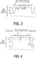
- FIG. 3 is a cross-sectional view taken along B-B of FIG. 2 .
- the narrow grooves 30 have a groove depth d within a range from 0.05 ⁇ (d/D) ⁇ 0.3 with respect to a groove depth D of the circumferential main groove 10.
- the groove depth d of the narrow grooves 30 is preferably within a range from 0.1 ⁇ (d/D) ⁇ 0.2 with respect to the groove depth D of the circumferential main groove 10.
- the narrow grooves 30 each have two or more groove depths and, in the present embodiment, the groove depths differ in the lateral narrow groove 31 and the circumferential narrow groove 32 of the narrow grooves 30.
- a groove depth d1 of the lateral narrow groove 31 is greater than a groove depth d2 of the circumferential narrow groove 32, and the groove depth d2 of the circumferential narrow groove 32 is within a range from 0.5 ⁇ (d2/d1) ⁇ 0.9 with respect to the groove depth d1 of the lateral narrow groove 31.
- the block 20 is defined into three or more small blocks 40 by the narrow grooves 30. That is, the lateral narrow groove 31 and the circumferential narrow grooves 32 of the narrow grooves 30 are connected to the circumferential main grooves 10 and the lug grooves 15, and the lateral narrow groove 31 and the circumferential narrow grooves 32 are connected to each other.
- the blocks 20 are divided into a plurality of regions in a plan view by the narrow grooves 30, each region being a small block 40. According to the present embodiment, four small blocks 40 are formed in each of the blocks 20.
- the blocks 20 are each separated in the tire circumferential direction by the lateral narrow grooves 31, and each of the regions separated in the tire circumferential direction are further separated in the tire lateral direction by the circumferential narrow grooves 32, thereby defining the block 20 into four of the small blocks 40.
- the small block 40 adjacent to the lug groove 15 that defines the leading side of the block 20 in the tire rotation direction and to the circumferential main groove 10 that defines the tire equator line CL side of the block 20 in the tire lateral direction is a leading-side block 41 that includes a portion of the block 20 positioned on the frontmost side in the tire rotation direction.
- each of the blocks 20 contacts the road surface first at a leading end in the tire rotation direction, bites into the road surface first at a leading end, then contacts the road surface at the very end of the trailing end in the tire rotation direction, and kicks off the road surface at the trailing end.
- an end portion on the tire equator line CL side in the tire lateral direction is positioned on the frontmost side in the tire rotation direction.
- the small block 40 adjacent to the lug groove 15 that defines the leading side of the block 20 in the tire rotation direction, and to the circumferential main groove 10 that defines the tire equator line CL side of the block 20 in the tire lateral direction is the small block 40 defined as the leading-side block 41 that first contacts the ground during rotation of the pneumatic tire 1.
- the small block 40 that includes a portion of the block 20 positioned on the backmost side in the tire rotation direction is a trailing-side block 42. That is, at the edge portion 21 on the trailing side of the block 20 in the tire rotation direction, an end portion on the outer side in the tire lateral direction is positioned on the backmost side in the tire rotation direction.
- the small block 40 adjacent to the lug groove 15 that defines the trailing side of the block 20 in the tire rotation direction, and to the circumferential main groove 10 that defines the outer side of the block 20 in the tire lateral direction is the small block 40 defined as the trailing-side block 42 that last separates from the road surface during rotation of the pneumatic tire 1.
- the two small blocks 40 other than the two small blocks 40 of the leading-side block 41 and the trailing-side block 42 are intermediate blocks 43. That is, of the four small blocks 40, the small block 40 adjacent to the lug groove 15 that defines the leading side of the block 20 in the tire rotation direction and to the circumferential main groove 10 that defines the outer side in the tire lateral direction, as well as the small block 40 adjacent to the lug groove 15 that defines the trailing side of the block 20 in the tire rotation direction and to the circumferential main groove 10 that defines the tire equator line CL side in the tire lateral direction are both intermediate blocks 43.
- the small blocks 40 thus formed have surface areas in the plan view of the block 20 configured so that the surface area of the trailing-side block 42 is greater than that of the leading-side block 41, and the surface areas of the intermediate blocks 43 are each greater than that of the trailing-side block 42. Further, the surface areas of the two intermediate blocks 43 are each greater than those of the leading-side block 41 and the trailing-side block 42. That is, the surface areas of the four small blocks 40 increase in the order of the leading-side block 41 ⁇ the trailing-side block 42 ⁇ the intermediate blocks 43 (both).
- the surface area of the leading-side block 41 is preferably within a range from 8 to 20%, both inclusive, of the surface area of the block 20, and the surface area of the trailing-side block 42 is preferably within a range from 12 to 30%, both inclusive, of the block 20.
- the two intermediate blocks 43 may have a relative relationship such that one of the surface areas of the two is greater than the other, as long as the surface areas of both are greater than those of the leading-side block 41 and the trailing-side block 42, any relative relationship between the two intermediate blocks 43 is not limited.
- the blocks 20 are configured so that a combined surface area of the two small blocks 40 positioned on the trailing side of the lateral narrow groove 31 in the tire rotation direction is greater than a combined surface area of the two small blocks 40 positioned on the leading side of the lateral narrow groove 31 in the tire rotation direction.
- the combined surface area of the two blocks 40 positioned on the leading side of the lateral narrow groove 31 in the tire rotation direction is within a range from 30 to 50%, both inclusive, of the surface area of the block 20.
- FIG. 4 is a cross-sectional view taken along C-C of FIG. 2 .
- the small block 40 adjacent to the lug groove 15 defining the leading side of the block 20 in the tire rotation direction includes a groove wall 16 on the lug groove 15 side that is inclined in a direction that causes a groove width of the lug groove 15 to decrease as the groove wall 16 extends from an opening portion 18 side toward a groove bottom 17 of the lug groove 15.
- the groove wall 16 of the lug groove 15 constituting the surface of the small block 40 on the leading side in the tire rotation direction is inclined with respect to the tire radial direction in the direction toward the leading side in the tire rotation direction as the groove wall 16 extends from the opening portion 18 side toward the groove bottom 17 side of the lug groove 15.
- An inclination angle ⁇ with respect to the tire radial direction of this groove wall 16 of the lug groove 15 is preferably from 5° to 15°, both inclusive.
- the lug groove 15 defining the trailing side of the block 20 in the tire rotation direction includes the groove wall 16 that forms an angle in substantially the tire radial direction.
- the narrow grooves 30 that define the small blocks 40 are similarly configured so that a groove wall 33 is formed at an angle substantially in the tire radial direction.
- the blocks 20 are each provided with a chamfer 19 on each end portion on the tread surface 3 side of the groove walls 16 of the lug grooves 15 defining both sides in the tire circumferential direction.
- This chamfer 19 is formed into a gently curved surface by the slight removal of a portion of the groove wall 16 of the lug groove 15 near the tread surface 3.
- the narrow grooves 30 are formed in the form described above, defining each of the blocks 20 into four of the small blocks 40. Further, in the blocks 20 of the two of the six block rows 25 positioned on both end sides in the tire lateral direction, only the lateral narrow groove 31 is formed as the narrow groove 30 and not the circumferential narrow groove 32.
- the pneumatic tire 1 according to the present embodiment is applied to a heavy duty pneumatic tire.
- the pneumatic tire 1 When mounted on a vehicle, the pneumatic tire 1 is mounted on a rim wheel and then mounted with the rim on the vehicle in an inflated state.
- the pneumatic tire 1 mounted on the rim wheel is mounted on a large vehicle such as a truck or a bus, for example.
- the pneumatic tire 1 When a vehicle with the pneumatic tire 1 mounted thereon runs, the pneumatic tire 1 rotates while the tread surface 3 of the tread surface 3 located at the bottom contacts the road surface.
- the vehicle When a vehicle with the pneumatic tire 1 mounted thereon run on dry road surfaces, the vehicle mainly run by a friction force between the tread surface 3 and the road surface. This friction force transmits a driving force and a braking force to the road surface and generates a swivel force.
- the vehicle runs while water between the tread surface 3 and the road surface enters the circumferential main grooves 10, the lug grooves 15, and the like, and is discharged by these grooves. In this way, the tread surface 3 readily contacts the road surface, allowing the vehicle to run by the friction force between the tread surface 3 and the road surface.
- the edges serving as boundary portions between the tread surface 3 and the grooves get caught on the icy and snowy road surfaces, making it possible to produce resistance between the tread surface 3 and the icy and snowy road surfaces and generate traction.
- the narrow grooves 30 are formed in the blocks 20, dividing the blocks 20 into the small blocks 40. Accordingly, the number of edge components of each of the blocks 20 increases and the number of edge components of the tread surface 3 in its entirety increases, making it possible to ensure traction performance as well as performance on snow and ice during running on icy and snowy road surfaces.
- the pneumatic tire 1 has a specified rotation direction and, among the plurality of small blocks 40 of the blocks 20, the leading-side block 41 has the smallest surface area.
- the leading-side block 41 is the small block 40 that first contacts the ground upon ground contact by the block 20.
- this leading-side block 41 having the smallest surface area, a hitting sound at the time of contact can be reduced. That is, when the block 20 separated from the road surface contacts the road surface, the hitting sound produced when the block 20 makes contact tends to increase in volume in proportion to an increase in the surface area of the block 20.
- the surface area of the leading-side block 41 that first contacts the ground upon ground contact by the block 20 being the smallest, the production of a loud hitting sound at the time of contact can be suppressed.
- the small block 40 adjacent to the circumferential main groove 10 defining the block 20 on the tire equator line CL side defined as a leading-side block 41 has the smallest surface area, thereby making it possible to effectively reduce the hitting sound when the region that has high ground contact pressure and readily produces a loud hitting sound upon ground contact contacts the ground. In this way, the noise produced when the tread surface 3 contacts the road surface during rotation of the pneumatic tire 1 can be reduced.
- the trailing-side block 42 has a greater surface area than that of the leading-side block 41
- the intermediate block 43 has a greater surface area than that of the trailing-side block 42, making it possible to make the surface area of the small blocks 40 positioned on the trailing side of the lateral narrow groove 31 in the tire rotation direction greater than that of the small blocks 40 positioned on the leading side. Accordingly, slippage on the trailing side of the block 20 in the tire rotation direction can be suppressed, and heal and toe wear can be suppressed. That is, in the block pattern, normally the trailing side of the block 20, that is, the area near the trailing end side in the tire rotation direction, readily slips at the time of kickoff of the block 20.
- the trailing side significantly wears compared to the leading side of the block 20, readily causing so-called heal and toe wear.
- the small blocks 40 positioned on the trailing side of the lateral narrow groove 31 in the tire rotation direction have a greater surface area than the small blocks 40 positioned on the leading side, and thus the small blocks 40 positioned on the trailing side of the lateral narrow groove 31 have high block rigidity compared to that of the small blocks 40 positioned on the leading side.
- the plurality of intermediate blocks 43 of the blocks 20 each have a greater surface area than those of the leading-side block 41 and the trailing-side block 42, and thus the total surface area of the plurality of small blocks 40 positioned in the periphery of an intersection portion where the circumferential main groove 10 and the lug groove 15 intersect can be made close in size among different intersections portions.
- at least one block 20 adjacent to the intersection portion is configured so that the leading-side block 41 or the trailing-side block 42 is positioned in the periphery of the intersection portion between the circumferential main groove 10 and the lug groove 15, and the other blocks 20 are configured so that the intermediate blocks 43 are positioned on the intersection portion side.
- the intermediate blocks 43 of the blocks 20 each have a greater surface area than those of the leading-side block 41 and the trailing-side block 42, and thus the total surface area of the plurality of small blocks 40 surrounding an intersection portion between the circumferential main groove 10 and the lug groove 15 can be made close in size among different intersection portions. Accordingly, between the plurality of intersection portions of the circumferential main groove 10 and the lug groove 15, each ground contact patch pressure when the plurality of small blocks 40 positioned in the periphery of the intersection portion contact the ground can be configured to be about the same, making it possible to suppress uneven wear caused by differences in ground contact patch pressure. As a result, uneven wear resistance can be more reliably improved.
- the narrow groove 30 has the groove depth d within the range from 0.05 ⁇ (d/D) ⁇ 0.3 with respect to the groove depth D of the circumferential main groove 10, making it possible to more reliably suppress uneven wear while reducing the hitting sound when the block 20 contacts the ground.
- the groove depth d of the narrow groove 30 is too small, making it difficult to appropriately divide the small blocks 40.
- the small blocks 40 may interconnect and contact the ground across a large surface area, possibly causing difficulties in reducing the hitting sound at the time of ground contact by the blocks 20.
- the groove depth d of the narrow groove 30 and the groove depth D of the circumferential main groove 10 is (d/D) > 0.3
- the groove depth d of the narrow groove 30 is too large, possibly causing the rigidity of the small blocks 40 defined by the narrow grooves 30 to be too low, which may make the rigidity of the small blocks 40 too low, causing uneven wear.
- the relationship between the groove depth d of the narrow groove 30 and the groove depth D of the circumferential main groove 10 is within the range from 0.05 ⁇ (d/D) ⁇ 0.3
- the small blocks 40 can be appropriately divided, making it possible to suppress uneven wear caused by an excessively low rigidity of the small blocks 40 while reducing the hitting sound at the time of ground contact by the blocks 20. As a result, it is possible to more reliably improve uneven wear resistance and reduce noise.
- the distance L1 in the tire circumferential direction from the portion of the block 20 positioned on the frontmost side in the tire rotation direction to the opening portion 34 that opens to the circumferential main groove 10 of the tire equator line CL side is within the range from 0.2 ⁇ (L1/L) ⁇ 0.5 with respect to the length L of the block 20 in the tire circumferential direction, making it possible to more reliably suppress the occurrence of block breakage while reducing the hitting sound at the time of ground contact by the blocks 20.
- the groove depths of the lateral narrow groove 31 and the circumferential narrow grooves 32 of the narrow grooves 30 are mutually different, making it possible to appropriately set relative rigidities between the small blocks 40 in accordance with relative disposed positions. As a result, it is possible to more reliably improve uneven wear resistance and reduce noise while maintaining performance on snow and ice.
- the lateral narrow groove 31 opens to the circumferential main grooves 10 on both ends, and the circumferential main groove 32 opens to the lug groove 15 on one end and the lateral narrow groove 31 on the other end, making it possible to dispose the circumferential narrow groove 32 in a preferred position in the tire lateral direction.
- the relative size of the surface area of each of the small blocks 40 can be set to a desired size. As a result, it is possible to more reliably improve uneven wear resistance and reduce noise while maintaining performance on snow and ice.
- the groove depth d1 of the lateral narrow groove 31 is greater than the groove depth d2 of the circumferential narrow groove 32, making it possible to increase the edge effect in the tire rotation direction by the lateral narrow groove 31 and more reliably improve traction performance when running on icy and snowy road surfaces. As a result, performance on snow and ice can be more reliably improved.
- the small block 40 adjacent to the lug groove 15 defining the leading side of the block 20 in the tire rotation direction includes the groove wall 16 on the lug groove 15 side that is inclined in a direction that causes the groove width of the lug groove 15 to decrease as the groove wall 16 extends from the opening portion 18 side toward the groove bottom 17 of the lug groove 15, making it possible to ensure rigidity at the time of tread-in of the block 20. As a result, breakage of the block 20 can be suppressed, making it possible to improve durability.
- the blocks 20 are each provided with the chamfer 19 on each of the end portions on the tread surface 3 side of the groove walls 16 of the lug grooves 15 defining both sides in the tire circumferential direction, making it possible to suppress a concentration of stress in the edge portions 21 of the block 20 in the tire circumferential direction and suppress breakage of the block 20 at the time of tread-in and kick-off from the road surface of the block 20. As a result, durability can be more reliably improved.
- the circumferential main groove 10 is formed into a zigzag shape that repeatedly oscillates in the tire lateral direction while extending in the tire circumferential direction, making air compressed by sound less likely to flow into the circumferential main groove 10 even when a hitting sound is produced at the time of ground contact by the blocks 20, thereby reducing the volume of the sound that flows outside the ground contact surface. As a result, noise can be more reliably reduced.
- FIG. 5 is a modified example of the pneumatic tire according to the embodiment, and is an explanatory diagram of a case where the lateral narrow groove is not provided with a bent portion.
- FIG. 6 is a detailed view of part D of FIG. 5 .
- the lateral narrow groove 31, as illustrated in FIGS. 5 and 6 may be linearly formed between the circumferential main grooves 10 positioned on both sides of the block 20 in the tire lateral direction.
- the shape of the lateral narrow groove 31 is not limited.
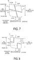
- FIG. 7 is a modified example of the pneumatic tire according to the present embodiment, and is an explanatory diagram of a case where the number of intersection points is other than two.
- the number of the intersection points 37 between the circumferential narrow groove 32 and the lateral narrow groove 31 may be one, for example, as illustrated in FIG. 7 .
- one lateral narrow groove 31 may be formed across the two circumferential main grooves 10 that define the block 20 in the tire lateral direction
- one circumferential narrow groove 32 may be formed across the two lug grooves 15 that define the block 20 in the tire circumferential direction, thereby intersecting the lateral narrow groove 31 at the one intersection point 37.
- the number of the intersection points 37 between the circumferential narrow groove 32 and the lateral narrow groove 31 may be other than two as long as the block 20 is defined into three or more small blocks 40.
- each of the blocks 20 is defined into the four small blocks 40, the number of the small blocks 40 formed in the one block 20 may be other than four.
- FIG. 8 is a modified example of the pneumatic tire according to the embodiment, and is an explanatory diagram of a case where the number of small blocks is other than four.
- the number of small blocks 40 formed in each of the blocks 20 may be three, for example, as illustrated in FIG. 8 .
- the number of small blocks 40 formed in each of the blocks 20 may be three or more, and the shape of the small blocks 40 may be a shape other than rectangular as in the intermediate block 43 illustrated in FIG. 8 .
- the lateral narrow groove 31 does not need to open to both circumferential main grooves 10 that define both sides of one block 20 in the tire lateral direction, and the circumferential narrow groove 32 does not need to open to both lug grooves 15 that define both sides of the block 20 in the tire circumferential direction.
- one lateral narrow groove 31 may simply open to one circumferential main groove 10
- one circumferential narrow groove 32 may simply open to one lug groove 15.
- the narrow groove 30 does not need to be formed across from one end side to the other end side of the block 20 in the tire lateral direction or the tire circumferential direction as long as one block 20 is defined into three or more small blocks 40.
- FIG. 9 is a modified example of the pneumatic tire according to the embodiment, and is an explanatory diagram of a case where the trailing-side block is disposed in a position other than the outer side in the tire lateral direction.
- the trailing-side block 42 may be adjacent to the lug groove 15 that defines the trailing side of the block 20 in the tire rotation direction, and to the circumferential main groove 10 that defines the tire equator line CL side of the block 20 in the tire rotation direction, as illustrated in FIG. 9 .
- the trailing-side block 42 may be in any position in the tire lateral direction as long as the trailing side block 42 is formed so as to include a back end of the block 20 in the tire rotation direction.
- the narrow grooves 30 are configured so that the groove depth d1 of the lateral narrow groove 31 is greater than the groove depth d2 of the circumferential narrow groove 32, the groove depth d2 of the circumferential narrow groove 32 may be greater than the groove depth d1 of the lateral narrow groove 31. Further, the groove depth of the narrow groove 30 may differ for each of the blocks 20, and may be formed at three or more depths within each of the blocks 20.
- the narrow grooves 30 may be configured so that, for example, the lateral narrow groove 31 is a regular groove in which the groove walls are continuously spaced apart even when the block 20 contacts the ground, and the circumferential narrow groove 32 may be formed by a sipe or the like, resulting in a mixture of regular groove and sipes.
- the narrow grooves 30 define the blocks 20 into three or more small blocks 40, making the surface area of the trailing-side block 42 greater than the surface area of the leading-side block 41, and the surface area of the intermediate block 43 greater than the surface areas of the leading-side block 41 and the trailing-side block 42, the presence or absence of the bent portion 35, the number of intersection points 37, the number of defined small blocks 40, the form of the narrow groove 30 itself, and the like are not limited.
- FIGS. 10A and 10B are tables showing the results of performance tests of pneumatic tires.
- performance evaluation tests conducted on a pneumatic tire of a conventional example, the pneumatic tire 1 according to the present invention, and pneumatic tire of a comparative example that is to be compared to the pneumatic tire 1 according to the present invention are described below.
- the performance evaluation tests were conducted on pass-by noise performance which is the performance of noise produced in association with the rolling of the pneumatic tire 1, uneven wear performance which is the performance of the uneven wear characteristics of the tread surface 3, and traction performance during running on icy and snowy road surfaces.
- the performance evaluation tests were conducted by mounting the pneumatic tire 1 having a size of 315/70R22.5 defined by ETRTO on a regular rim, adjusting the air pressure to 900 kPa, mounting the tire onto a 2-D test vehicle, and then running tests.
- the evaluation method of each test item was as follows. That is, pass-by noise performance was evaluated on the basis of the measured volume of exterior pass-by noise in accordance with a tire noise test method defined in ECE Regulation No. 117 Revision 2 (ECE R117-02).
- the test vehicle run from an area at a sufficient distance in front of a noise measurement section, the engine was stopped immediately in front of the section, and a maximum noise level dB (noise level within a frequency range of from 800 to 1200 Hz) in the noise measurement section during coasting was measured at a plurality of speeds obtained by substantially equally dividing a speed range into eight or more intervals of ⁇ 10 km/h with respect to a standard speed, and setting the average as the exterior pass-by noise.
- dB noise level within a frequency range of from 800 to 1200 Hz
- the maximum noise level dB is a sound pressure dB (A) measured through an A-characteristic frequency correction circuit using a stationary microphone installed 7.5 m laterally from a run center line at an intermediate point in the noise measurement section and at a height of 1.2 m from the road surface.
- Pass-by noise performance is expressed based on the measurement result by using Conventional Example described later as an index value of 100.
- a larger index value indicates a smaller sound pressure dB, that is, a smaller pass-by noise, and thus greater level of excellence in pass-by noise performance.
- uneven wear performance was evaluated by visually evaluating uneven wear, specifically heal and toe wear, of the tread surface 3 after conducting a 100000-km road test in the test vehicle. Uneven wear performance is expressed by using the evaluation result of Conventional Example described later as an index value of 100. A larger index value indicates a smaller degree of uneven wear and thus a greater degree of excellence in uneven wear performance. Further, traction performance was evaluated by evaluating acceleration performance on snow under the test conditions defined in UNECE Regulation No. 117 Revision 3 (ECE R117-02). Traction performance is expressed by using the evaluation result of Conventional Example described later as an index value of 100. A larger index value indicates better acceleration performance on snow and a greater degree of excellence in traction performance.
- the circumferential main groove 10 forms a zigzag shape, but the surface areas of the small blocks 40 are not configured so as to form the relationship leading-side block 41 ⁇ trailing side block 42 ⁇ intermediate block 43.
- the circumferential main groove 10 forms a zigzag shape, and the surface areas of the small blocks 40 are configured so as to form the relationship leading-side block 41 ⁇ trailing side block 42 ⁇ intermediate block 43.
- the depths of the narrow groove 30 with respect to that of the circumferential main grooves 10, the position of the opening portion 34 of the lateral narrow groove 31 with respect to the length of the block 20, whether the narrow grooves 30 have two or more types of groove depths, whether the groove wall 16 of the lug groove 15 defining the leading side of the block 20 in the tire rotation direction is inclined, and the presence or absence of the chamfer 19 of the lug groove 15 are each different.
- the results of the evaluation tests conducted using these pneumatic tires 1 indicate that the pneumatic tires 1 of the Examples 1 to 11 can improve pass-by noise performance, uneven wear performance, and traction performance in contrast to Conventional Example and Comparative Example. That is, the pneumatic tires 1 according to Examples 1 to 11 can improve uneven wear resistance and reduce noise while maintaining traction performance on snow and ice.
Landscapes
- Engineering & Computer Science (AREA)
- Mechanical Engineering (AREA)
- Tires In General (AREA)
Description
- The present invention relates to a pneumatic tire.
- In a pneumatic tire, in order to discharge water between a tread surface and a road surface during running on wet road surfaces, a plurality of grooves are formed in the tread surface. These grooves in the tread surface, however, cause noise and uneven wear when the vehicle run. Thus, among the pneumatic tires in the related art, there are tires that achieve reduced noise and uneven wear as a result of considerations made to a shape and an arrangement of the grooves.
- For example, in the pneumatic tire described in
Patent Document 1, blocks of a so-called block pattern are each made into a polygon having six sides or more, and each other leading-side edges of the blocks of respective rows during the rolling of the tire under a load are provided with interval in a tread circumferential direction, thereby preventing the occurrence of large collision noise caused by a plurality of the blocks of the respective block rows simultaneously colliding with the road surface. Further, in the pneumatic tire described inPatent Document 2, an open sipe that divides the block in a tire circumferential direction is formed in the blocks of the block pattern, and the open sipe is bent so as to include a lateral sipe portion where the open sipe extends in a tire lateral direction, and a circumferential sipe portion where the open sipe extends in the tire circumferential direction, the circumferential sipe portion being disposed in the middle of the lateral sipe portion, thereby suppressing abnormal wear and improving performance on snow and ice. -
- Patent Document 1:
JP 5425802 B - Patent Document 2:
JP 4715890 B - Here, in the block pattern, a trailing side of each block readily wears, causing a difference in a degree of wear between a leading side and a trailing side, increasing uneven wear susceptibility. While noise can be suppressed by shifting leading-side edges of blocks in the tread circumferential direction between different block rows as in
Patent Document 1, difficulties arise in suppressing the uneven wear caused by such a difference in the degree of wear between the leading side and the trailing side of each block. Further, while collision noise caused by the plurality of leading-side edges of the blocks simultaneously colliding with the road surface can be reduced by shifting the leading-side edges of the blocks in the tread circumferential direction between different block rows as inPatent Document 1, such a shift does not lead to a reduction in noise from the perspective of an individual block. - Further, while uneven wear caused by a difference in the degree of wear between the leading side and the trailing side can be suppressed to a certain degree by bending open sipes provided in the blocks as in
Patent Document 2, the collision noise when the block collides with the road surface does not change, making the reduction of noise produced by each block difficult. Further, when open sipes are configured so that the circumferential sipe portion is positioned in the middle of the lateral sipe portion, the edge components in the tire circumferential direction are small with respect to the edge components in the tire lateral direction, and thus the edge effect may not be freely exhibited depending on the direction of the load that acts on a ground contact region of the tread surface on snow and ice. In this way, satisfaction of all of these, that is, uneven wear resistance, noise reduction, and performance on snow and ice, has been extremely difficult. - In light of the foregoing, an object of the present invention is to provide a pneumatic tire capable of improving uneven wear resistance and reducing noise while maintaining performance on snow and ice.
- To solve the problems described above and achieve the object described above, a pneumatic tire according to the present invention is a pneumatic tire having a specified rotation direction, including a tread surface, a plurality of circumferential main grooves formed on the tread surface and extending in a tire circumferential direction, a plurality of lug grooves formed on the tread surface and extending in a tire lateral direction, and a plurality of blocks, both sides of each of the blocks being defined by the lug grooves in the tire circumferential direction and at least one end portion of each of the blocks being defined by the circumferential main grooves in the tire lateral direction. The lug grooves are each configured with at least a portion thereof that defines a leading side of the block in a tire rotation direction inclined toward a trailing side in the tire rotation direction as that portion extends outward in a tire lateral direction from a tire equator line side. The blocks each include a narrow groove that opens to the circumferential main groove and the lug groove, and the block is defined into three or more small blocks by the narrow groove. The plurality of small blocks are configured so that, among the plurality of small blocks, the small block adjacent to the lug groove defining the leading side of the block in the tire rotation direction and to the circumferential main groove defining the tire equator line side of the block in the tire lateral direction is a leading-side block with a portion thereof positioned on a frontmost side of the block in the tire rotation direction, Among the plurality of small blocks, the small block with a portion thereof positioned on a backmost side of the block in the tire rotation direction is a trailing-side block, and the small block other than the leading-side block and the trailing-side block is an intermediate block. The plurality of small blocks are configured so that the trailing-side block has a surface area greater than that of the leading-side block, and the intermediate block has a surface area greater than that of the trailing-side block.
- Further, in the pneumatic tire described above, preferably the blocks each includes a plurality of the intermediate blocks, and the plurality of intermediate blocks each have a surface area greater than those of the leading-side block and the trailing-side block.
- Further, in the pneumatic tire described above, preferably the narrow groove has a groove depth d within a range from 0.05 ≤ (d/D) ≤ 0.3 with respect to a groove depth D of the circumferential main groove.
- Further, in the pneumatic tire described above, preferably the narrow groove opens to the circumferential main groove defining the tire equator line side of the block in the tire lateral direction, and a distance L1 in the tire circumferential direction from a portion positioned on the frontmost side of the block in the tire rotation direction to an opening portion that opens to the circumferential main groove is within a range from 0.2 ≤ (L1/L) ≤ 0.5 with respect to a length L of the block in the tire circumferential direction.
- Further, in the pneumatic tire described above, preferably the narrow groove includes a lateral narrow groove that extends in the tire lateral direction and opens to the circumferential main groove on at least on one end, and a circumferential narrow groove that extends in the tire circumferential direction and opens to the lug groove on at least one end, the lateral narrow groove and the circumferential narrow groove having mutually different groove depths.
- Further, in the pneumatic tire described above, preferably the narrow groove includes a lateral narrow groove that extends in the tire lateral direction and opens to the circumferential main grooves on both ends, and a circumferential narrow groove that extends in the tire circumferential direction, opens to the lug groove on one end, and opens to the lateral narrow groove on the other end.
- Further, in the pneumatic tire described above, preferably the lateral narrow groove has a groove depth that is greater than the groove depth of the circumferential narrow groove.
- Further, in the pneumatic tire described above, preferably the small blocks are configured so that, among the plurality of small blocks, the small block adjacent to the lug groove defining the leading side of the block in the tire rotation direction includes a groove wall on the lug groove side that is inclined in a direction that causes a groove width of the lug groove to decrease as the groove wall extends from the opening portion side toward a groove bottom of the lug groove.
- Further, in the pneumatic tire described above, preferably the blocks are each provided with a chamfer on each end portion on the tread surface side of the groove walls of the lug grooves defining both sides in the tire circumferential direction.
- A pneumatic tire according to the present invention achieves the effect of reducing uneven wear resistance and noise while maintaining traction performance on snow and ice.
-
- FIG. 1
- is a plan view illustrating a tread surface of a pneumatic tire according to an embodiment.
- FIG. 2
- is a detailed view of part A of
FIG. 1 . - FIG. 3
- is a cross-sectional view taken along B-B of
FIG. 2 . - FIG. 4
- is a cross-sectional view taken along C-C of
FIG. 2 . - FIG. 5
- is a modified example of the pneumatic tire according to the embodiment, and is an explanatory diagram of a case where a lateral narrow groove is not provided with a bent portion.
- FIG. 6
- is a detailed view of part D of
FIG. 5 . - FIG. 7
- is a modified example of the pneumatic tire according to the embodiment, and is an explanatory diagram of a case where the number of intersection points is other than two.
- FIG. 8
- is a modified example of the pneumatic tire according to the embodiment, and is an explanatory diagram of a case where the number of small blocks is other than four.
- FIG. 9
- is a modified example of the pneumatic tire according to the embodiment, and is an explanatory diagram of a case where the trailing-side block is disposed in a position other than the outer side in the tire lateral direction.
- FIG. 10A
- is a table showing the results of performance tests of pneumatic tires.
- FIG. 10B
- is a table showing the results of performance tests of pneumatic tires.
- Pneumatic tires according to embodiments of the present invention are described in detail below with reference to the drawings. However, the invention is not limited to these embodiments. Constituents of the following embodiments include elements that are essentially identical or that can be substituted or easily conceived by one skilled in the art.
- Herein, "tire lateral direction" refers to the direction that is parallel with a rotation axis of a pneumatic tire. "Inward in the tire lateral direction" refers to the direction toward the tire equatorial plane in the tire lateral direction. "Outward in the tire lateral direction" refers to the direction opposite the direction toward the tire equatorial plane in the tire lateral direction. Further, "tire radial direction" refers to the direction orthogonal to the tire rotation axis. "Tire circumferential direction" refers to the direction of rotation with the tire rotation axis as the center of rotation.
-
FIG. 1 is a plan view of a tread surface of a pneumatic tire according to an embodiment of the present invention. Apneumatic tire 1 illustrated inFIG. 1 is provided with atread portion 2 in an outermost portion in the tire radial direction. The surface of thetread portion 2, i.e., the portion that contacts the road surface when a vehicle (not illustrated) mounted with thepneumatic tire 1 runs, is formed as atread surface 3. A plurality of circumferentialmain grooves 10 extending in the tire circumferential direction and a plurality oflug grooves 15 extending in the tire lateral direction are each formed in thetread portion 3, and a plurality ofblocks 20 serving as land portions are formed by the circumferentialmain grooves 10 and thelug grooves 15. That is, theblocks 20 are defined by thelug grooves 15 on both sides in the tire circumferential direction, and by the circumferentialmain grooves 10 on at least one end portion in the tire lateral direction, and thus each of theblocks 20 has a substantially quadrangular shape. - Specifically, five circumferential
main grooves 10 are formed aligned in the tire lateral direction, each of the five circumferentialmain grooves 10 are formed with repeated bending in the tire lateral direction while extending in the tire circumferential direction. That is, the circumferentialmain grooves 10 extending in the tire circumferential direction are formed in a zigzag shape. Further, thelug grooves 15 are configured so that thelug grooves 15 that do not penetrate the circumferentialmain grooves 10 and are adjacent to each other via the circumferentialmain grooves 10 are formed in positions that differ in the tire circumferential direction. The circumferentialmain grooves 10 here have a groove width within a range from 3 to 10 mm, both inclusive, and a groove depth within a range from 7 to 25 mm, both inclusive. Further, thelug grooves 15 here have a groove width within a range from 4 to 12 mm, both inclusive, and a groove depth within a range from 5 to 25 mm, both inclusive. - The
blocks 20 defined by the circumferentialmain grooves 10 and thelug grooves 15 are disposed between circumferentialmain grooves 10 adjacent to each other as well as on the outer side in the tire lateral direction of each of the two circumferentialmain grooves 10 positioned most outward in the tire lateral direction. Further, a plurality of theblocks 20 positioned in substantially the same position in the tire lateral direction are aligned in series in the tire circumferential direction via thelug grooves 15, formingblock rows 25 each in a row shape. Such ablock row 25 is formed in four locations between five circumferentialmain grooves 10, and in two locations outward in the tire lateral direction of the two circumferentialmain grooves 10 positioned most outward in the tire lateral direction, forming six rows in total. These sixblock rows 25 are aligned in the tire lateral direction on thetread surface 3. The tread pattern on thetread surface 3 of thepneumatic tire 1 according to the present embodiment is thus a so-called block pattern provided with land portions formed by the plurality ofblocks 20. - Further, the
pneumatic tire 1 according to the present embodiment has a specified rotation direction when mounted on a vehicle. In the description below, a leading side in the tire rotation direction is the rotation direction side when thepneumatic tire 1 rotates in the specified direction and, is the side that first contacts and first separates from the road surface when thepneumatic tire 1 is mounted on a vehicle, rotated in the specified direction, and run. Further, a trailing side in the tire rotation direction is a side opposite to the rotation direction side when thepneumatic tire 1 rotates in the specified direction and, is the side that later contacts and separates from the road surface when thepneumatic tire 1 is mounted on a vehicle, rotated in the specified direction, and run. Each of thelug grooves 15 is inclined in a direction toward the trailing side in the tire rotation direction, as it goes from the tire equator line CL side to an outer side in the tire lateral direction. That is, thelug grooves 15 are each inclined in a direction toward the trailing side in the tire rotation direction, from an inner side toward the outer side in the tire lateral direction while extending in the tire circumferential direction. Note that thelug grooves 15 do not need to be inclined in the tire circumferential direction while extending in the tire lateral direction in all positions in which thelug grooves 15 define theblocks 20 in the tire circumferential direction. At least a portion of thelug grooves 15 that define the leading side of theblocks 20 in the tire rotation direction may be inclined in a direction toward the trailing side in the tire rotation direction, as it goes from the tire equator line CL side toward the outer side in the tire lateral direction. - Further, each of the
blocks 20 of the sixblock rows 25 includesnarrow grooves 30. In the four of the sixblock rows 25 other than the two rows outward in the tire lateral direction, thenarrow grooves 30 open to the circumferentialmain grooves 10 and thelug grooves 15 that define each of theblocks 20. Further, in the two of the sixblock rows 25 outward in the tire lateral direction, thenarrow grooves 30 open to the circumferentialmain groove 10 that defines each of theblocks 20 as well as to the outer sides of theblocks 20 in the tire lateral direction. Further, thenarrow grooves 30 are each formed in substantially the same form in each of theblocks 20 of the fourblock rows 25 other than the two rows outward in the tire lateral direction, and in substantially the same form in each of theblocks 20 of the twoblock rows 25 outward in the tire lateral direction. - The
narrow grooves 30 here each have a groove width within a range from 0.8 to 2 mm, both inclusive, and a groove depth within a range from 0.7 to 15 mm, both inclusive, and include a sipe. Here, "sipe" refers to a groove formed into a narrow shape in thetread surface 3. When thepneumatic tire 1 is mounted on a regular rim, inflated to a regular internal pressure, and placed under no load conditions, wall surfaces constituting the sipe do not come into contact with each other. When the sipe is positioned in a portion of a ground contact surface formed on a flat plate with a load applied in a vertical direction on the plate, or when theblock 20 where the sipe is formed collapses, the wall surfaces constituting the sipe, or at least portions of areas disposed on the wall surfaces, come into contact with each other as a result of deformation of theblock 20. Here, "regular rim" refers to a "standard rim" defined by the Japan Automobile Tyre Manufacturers Association Inc. (JATMA), a "design rim" defined by the Tire and Rim Association, Inc. (TRA), or a "measuring rim" defined by the European Tyre and Rim Technical Organisation (ETRTO). "Regular internal pressure" refers to "maximum air pressure" defined by JATMA, a maximum value given in "Tire Load Limits at Various Cold Inflation Pressures" defined by TRA, or "Inflation Pressures" defined by ETRTO. Thenarrow grooves 30 in the present embodiment, even when positioned on the ground contact surface, maintain a state in which the groove walls are separated from each other, and include such a sipe. -
FIG. 2 is a detailed view of part A ofFIG. 1 . Thelug grooves 15 that define both sides of theblock 20 in the tire circumferential direction incline in a direction toward the trailing side in the tire rotation direction, as it goes from the tire equator line CL side toward the outer side in the tire lateral direction, and thus an end portion on the tire equator line CL side in the tire lateral direction of theblock 20 is positioned on a frontmost side in the tire rotation direction at anedge portion 21 on the leading side in the tire rotation direction. Further, at theedge portion 21 on the trailing side of theblock 20 in the tire rotation direction, an end portion on the outer side in the tire lateral direction is positioned on the backmost side in the tire rotation direction. - Further, in the
blocks 20 constituting the fourblock rows 25 other than the twoblock rows 25 positioned on both end sides in the tire lateral direction, thenarrow grooves 30 include a lateralnarrow groove 31 extending in the tire lateral direction, and circumferentialnarrow grooves 32 extending in the tire circumferential direction. The lateralnarrow groove 31 of thenarrow grooves 30 has at least one end that opens to the circumferentialmain grooves 10 defining theblock 20. Further, the circumferentialnarrow grooves 32 have at least one end that opens to thelug grooves 15 defining theblock 20. - Specifically, the lateral
narrow groove 31 extending in the tire lateral direction is configured so that one end opens to the circumferentialmain groove 10 that defines the tire lateral direction CL side of theblock 20 in the tire lateral direction, and another end opens to the circumferentialmain groove 10 that defines the outer side of theblock 20 in the tire lateral direction. Both ends of the lateralnarrow groove 31 thus form openingportions 34 that respectively open to the circumferentialmain grooves 10. - Further, the lateral
narrow groove 31 bends at two locations while extending in the tire lateral direction, and includes twobent portions 35. The twobent portions 35 bend in directions such that the portion of the lateralnarrow groove 31 positioned outward from thebent portion 35 in the tire lateral direction is positioned further to the trailing side in the tire rotation direction than the portion of the lateralnarrow groove 31 positioned inward from thebent portion 35 in the tire lateral direction. These twobent portions 35 are positioned in a central region of theblock 20 in the tire lateral direction at different positions in the tire circumferential direction, and the portion of the lateralnarrow groove 31 between thebent portions 35 extends in the tire circumferential direction at a short length. In other words, the lateralnarrow groove 31 bends at the twobent portions 35, forming a so-called crank-like shape. - Further, two of the circumferential
narrow grooves 32 are provided, and these two circumferentialnarrow grooves 32 are positioned further outward of theblock 20 in the tire lateral direction than thebent portions 35 of the lateralnarrow groove 31. That is, one circumferentialnarrow groove 32, of the two circumferentialnarrow grooves 32, is positioned inward from thebent portions 35 in the tire lateral direction, and the other circumferentialnarrow groove 32 is positioned outward from thebent portions 35 in the tire lateral direction. The circumferentialnarrow groove 32, of the two circumferentialnarrow groove 32, positioned inward from thebent portions 35 in the tire lateral direction is positioned on the leading side of the lateralnarrow groove 31 in the tire rotation direction, and the circumferentialnarrow groove 32 positioned outward from thebent portions 35 in the tire lateral direction is positioned on the trailing side of the lateralnarrow groove 31 in the tire rotation direction. - The circumferential
narrow grooves 32, at these positions, are each configured so that one end opens to thelug groove 15, and the other end intersects the lateralnarrow groove 31, connecting and opening to the lateralnarrow groove 31. Specifically, the circumferentialnarrow groove 32 positioned inward from thebent portions 35 in the tire lateral direction is configured so that an end portion on the leading side in the tire rotation direction is an openingportion 34 that opens to thelug groove 15, and an end portion on the trailing side in the tire rotation direction is connected to the lateralnarrow groove 31. Further, the circumferentialnarrow groove 32 positioned outward from thebent portions 35 in the tire lateral direction is configured so that an end portion on the trailing side in the tire rotation direction is an openingportion 34 that opens to thelug groove 15, and an end portion on the leading side in the tire rotation direction is connected to the lateralnarrow groove 31. - A portion where the circumferential
narrow groove 32 and the lateralnarrow groove 31 intersect form anintersection point 37, and thenarrow grooves 30 include two intersection points 37 formed by the two circumferentialnarrow grooves 32 intersecting one lateralnarrow groove 31. That is, thenarrow grooves 30 is configured to include twointersection points 37 by two circumferentialnarrow grooves 32 being provided as one of thenarrow grooves 30, the two circumferentialnarrow grooves 32 intersecting the lateralnarrow groove 31, which is anothernarrow groove 30. Thebent portions 35 of the lateralnarrow groove 31 are positioned between the twointersection points 37 in the tire lateral direction. - Further, in the
narrow grooves 30, a distance L1 in the tire circumferential direction from a portion positioned on the frontmost side of theblock 20 in the tire rotation direction to the openingportion 34 that opens to the circumferentialmain groove 10 that defines the tire equator line CL side is within a range from 0.2 ≤ (L1/L) ≤ 0.5 with respect to a length L of theblock 20 in the tire circumferential direction. That is, the openingportion 34 of thenarrow groove 30 that opens to the circumferentialmain groove 10 that defines the tire equator line CL side opens to the circumferentialmain groove 10 at a position on the leading side from a center of theblock 20 in the tire rotation direction. Note that thelug grooves 15 that define both sides of theblock 20 in the tire circumferential direction incline in the tire circumferential direction with respect to the tire lateral direction, and thus the length L of theblock 20 in this case is a distance between portions on both sides of theblock 20 in the tire circumferential direction that are farthest apart in the tire circumferential direction. - Further, the
block 20 is configured so that, at theedge portion 21 on the leading side in the tire rotation direction, the end portion on the tire equator line CL side in the tire lateral direction is positioned on the frontmost side in the tire rotation direction, and thus the distance L1 is the distance in the tire circumferential direction between the end portion on the tire equator line CL side of theedge portion 21 on the leading side in the tire rotation direction, and the openingportion 34 that opens to the circumferentialmain groove 10 that defines the tire equator line CL side. Thenarrow groove 30 opens to the circumferentialmain groove 10 with the distance L1 from a leading end of theblock 20 in the tire rotation direction to the openingportion 34 that opens to the circumferentialmain groove 10 that defines the tire equator line CL side being within a range from 20 to 50%, both inclusive, with respect to the length L of theblock 20 in the tire circumferential direction. Note that the position of the openingportion 34 in this case is a center position of an opening width of the openingportion 34 in the tire circumferential direction. Further, the relationship between the distance L1 in the tire circumferential direction to the openingportion 34 that opens to the circumferentialmain groove 10 on the tire equator line CL side and the length L of theblock 20 in the tire circumferential direction is preferably within a range from 0.3 ≤ (L1/L) ≤ 0.4. -
FIG. 3 is a cross-sectional view taken along B-B ofFIG. 2 . Thenarrow grooves 30 have a groove depth d within a range from 0.05 ≤ (d/D) ≤ 0.3 with respect to a groove depth D of the circumferentialmain groove 10. The groove depth d of thenarrow grooves 30 is preferably within a range from 0.1 ≤ (d/D) ≤ 0.2 with respect to the groove depth D of the circumferentialmain groove 10. Further, thenarrow grooves 30 each have two or more groove depths and, in the present embodiment, the groove depths differ in the lateralnarrow groove 31 and the circumferentialnarrow groove 32 of thenarrow grooves 30. Specifically, a groove depth d1 of the lateralnarrow groove 31 is greater than a groove depth d2 of the circumferentialnarrow groove 32, and the groove depth d2 of the circumferentialnarrow groove 32 is within a range from 0.5 ≤ (d2/d1) ≤ 0.9 with respect to the groove depth d1 of the lateralnarrow groove 31. - The
block 20 is defined into three or moresmall blocks 40 by thenarrow grooves 30. That is, the lateralnarrow groove 31 and the circumferentialnarrow grooves 32 of thenarrow grooves 30 are connected to the circumferentialmain grooves 10 and thelug grooves 15, and the lateralnarrow groove 31 and the circumferentialnarrow grooves 32 are connected to each other. Thus, theblocks 20 are divided into a plurality of regions in a plan view by thenarrow grooves 30, each region being asmall block 40. According to the present embodiment, foursmall blocks 40 are formed in each of theblocks 20. That is, theblocks 20 are each separated in the tire circumferential direction by the lateralnarrow grooves 31, and each of the regions separated in the tire circumferential direction are further separated in the tire lateral direction by the circumferentialnarrow grooves 32, thereby defining theblock 20 into four of the small blocks 40. - Of these four
small blocks 40, thesmall block 40 adjacent to thelug groove 15 that defines the leading side of theblock 20 in the tire rotation direction and to the circumferentialmain groove 10 that defines the tire equator line CL side of theblock 20 in the tire lateral direction is a leading-side block 41 that includes a portion of theblock 20 positioned on the frontmost side in the tire rotation direction. - That is, when the
tread surface 3 of thepneumatic tire 1 contacts the road surface, contact is made from the portion relatively positioned on the leading side in the tire rotation direction and thus, in each of theblocks 20 as well, contact is made from the leading side in the tire rotation direction. Further, when theblock 20 in contact with the ground separates from the road surface, separation is gradually made from the leading side to the trailing side in the tire rotation direction, with the portion positioned on the backmost side in the tire rotation direction separating last. As a result, during rotation of thepneumatic tire 1, each of theblocks 20 contacts the road surface first at a leading end in the tire rotation direction, bites into the road surface first at a leading end, then contacts the road surface at the very end of the trailing end in the tire rotation direction, and kicks off the road surface at the trailing end. - Furthermore, in the
pneumatic tire 1 according to the present embodiment, at theedge portion 21 on the leading side of theblock 20 in the tire rotation direction, an end portion on the tire equator line CL side in the tire lateral direction is positioned on the frontmost side in the tire rotation direction. Thus, of the foursmall blocks 40, thesmall block 40 adjacent to thelug groove 15 that defines the leading side of theblock 20 in the tire rotation direction, and to the circumferentialmain groove 10 that defines the tire equator line CL side of theblock 20 in the tire lateral direction is thesmall block 40 defined as the leading-side block 41 that first contacts the ground during rotation of thepneumatic tire 1. - In contrast, of the four
small blocks 40, thesmall block 40 that includes a portion of theblock 20 positioned on the backmost side in the tire rotation direction is a trailing-side block 42. That is, at theedge portion 21 on the trailing side of theblock 20 in the tire rotation direction, an end portion on the outer side in the tire lateral direction is positioned on the backmost side in the tire rotation direction. Thus, of the foursmall blocks 40, thesmall block 40 adjacent to thelug groove 15 that defines the trailing side of theblock 20 in the tire rotation direction, and to the circumferentialmain groove 10 that defines the outer side of theblock 20 in the tire lateral direction is thesmall block 40 defined as the trailing-side block 42 that last separates from the road surface during rotation of thepneumatic tire 1. - Further, of the four
small blocks 40, the twosmall blocks 40 other than the twosmall blocks 40 of the leading-side block 41 and the trailing-side block 42 areintermediate blocks 43. That is, of the foursmall blocks 40, thesmall block 40 adjacent to thelug groove 15 that defines the leading side of theblock 20 in the tire rotation direction and to the circumferentialmain groove 10 that defines the outer side in the tire lateral direction, as well as thesmall block 40 adjacent to thelug groove 15 that defines the trailing side of theblock 20 in the tire rotation direction and to the circumferentialmain groove 10 that defines the tire equator line CL side in the tire lateral direction are bothintermediate blocks 43. - The
small blocks 40 thus formed have surface areas in the plan view of theblock 20 configured so that the surface area of the trailing-side block 42 is greater than that of the leading-side block 41, and the surface areas of theintermediate blocks 43 are each greater than that of the trailing-side block 42. Further, the surface areas of the twointermediate blocks 43 are each greater than those of the leading-side block 41 and the trailing-side block 42. That is, the surface areas of the foursmall blocks 40 increase in the order of the leading-side block 41 < the trailing-side block 42 < the intermediate blocks 43 (both). - Note that the surface area of the leading-
side block 41 is preferably within a range from 8 to 20%, both inclusive, of the surface area of theblock 20, and the surface area of the trailing-side block 42 is preferably within a range from 12 to 30%, both inclusive, of theblock 20. Further, the twointermediate blocks 43 may have a relative relationship such that one of the surface areas of the two is greater than the other, as long as the surface areas of both are greater than those of the leading-side block 41 and the trailing-side block 42, any relative relationship between the twointermediate blocks 43 is not limited. - Furthermore, the
blocks 20 are configured so that a combined surface area of the twosmall blocks 40 positioned on the trailing side of the lateralnarrow groove 31 in the tire rotation direction is greater than a combined surface area of the twosmall blocks 40 positioned on the leading side of the lateralnarrow groove 31 in the tire rotation direction. Specifically, in theblock 20, preferably the combined surface area of the twoblocks 40 positioned on the leading side of the lateralnarrow groove 31 in the tire rotation direction is within a range from 30 to 50%, both inclusive, of the surface area of theblock 20. -
FIG. 4 is a cross-sectional view taken along C-C ofFIG. 2 . Among the foursmall blocks 40, thesmall block 40 adjacent to thelug groove 15 defining the leading side of theblock 20 in the tire rotation direction includes agroove wall 16 on thelug groove 15 side that is inclined in a direction that causes a groove width of thelug groove 15 to decrease as thegroove wall 16 extends from an openingportion 18 side toward a groove bottom 17 of thelug groove 15. In other words, thegroove wall 16 of thelug groove 15 constituting the surface of thesmall block 40 on the leading side in the tire rotation direction is inclined with respect to the tire radial direction in the direction toward the leading side in the tire rotation direction as thegroove wall 16 extends from the openingportion 18 side toward the groove bottom 17 side of thelug groove 15. An inclination angle θ with respect to the tire radial direction of thisgroove wall 16 of thelug groove 15 is preferably from 5° to 15°, both inclusive. - In contrast to the
lug groove 15 defining the leading side of theblock 20 in the tire rotation direction including thegroove wall 16 thus inclined with respect to the tire radial direction, thelug groove 15 defining the trailing side of theblock 20 in the tire rotation direction includes thegroove wall 16 that forms an angle in substantially the tire radial direction. Further, thenarrow grooves 30 that define thesmall blocks 40 are similarly configured so that agroove wall 33 is formed at an angle substantially in the tire radial direction. - Furthermore, the
blocks 20 are each provided with achamfer 19 on each end portion on thetread surface 3 side of thegroove walls 16 of thelug grooves 15 defining both sides in the tire circumferential direction. Thischamfer 19 is formed into a gently curved surface by the slight removal of a portion of thegroove wall 16 of thelug groove 15 near thetread surface 3. - In the
blocks 20 of the four of the sixblock rows 25 other than the twoblock rows 25 positioned on both end sides in the tire lateral direction, thenarrow grooves 30 are formed in the form described above, defining each of theblocks 20 into four of the small blocks 40. Further, in theblocks 20 of the two of the sixblock rows 25 positioned on both end sides in the tire lateral direction, only the lateralnarrow groove 31 is formed as thenarrow groove 30 and not the circumferentialnarrow groove 32. - The
pneumatic tire 1 according to the present embodiment thus configured is applied to a heavy duty pneumatic tire. When mounted on a vehicle, thepneumatic tire 1 is mounted on a rim wheel and then mounted with the rim on the vehicle in an inflated state. Thepneumatic tire 1 mounted on the rim wheel is mounted on a large vehicle such as a truck or a bus, for example. - When a vehicle with the
pneumatic tire 1 mounted thereon runs, thepneumatic tire 1 rotates while thetread surface 3 of thetread surface 3 located at the bottom contacts the road surface. When a vehicle with thepneumatic tire 1 mounted thereon run on dry road surfaces, the vehicle mainly run by a friction force between thetread surface 3 and the road surface. This friction force transmits a driving force and a braking force to the road surface and generates a swivel force. Further, when the vehicle runs on wet road surfaces, the vehicle runs while water between thetread surface 3 and the road surface enters the circumferentialmain grooves 10, thelug grooves 15, and the like, and is discharged by these grooves. In this way, thetread surface 3 readily contacts the road surface, allowing the vehicle to run by the friction force between thetread surface 3 and the road surface. - Further, when the vehicle runs on icy and snowy road surfaces, the edges serving as boundary portions between the
tread surface 3 and the grooves get caught on the icy and snowy road surfaces, making it possible to produce resistance between thetread surface 3 and the icy and snowy road surfaces and generate traction. Additionally, in thepneumatic tire 1 according to the present embodiment, thenarrow grooves 30 are formed in theblocks 20, dividing theblocks 20 into the small blocks 40. Accordingly, the number of edge components of each of theblocks 20 increases and the number of edge components of thetread surface 3 in its entirety increases, making it possible to ensure traction performance as well as performance on snow and ice during running on icy and snowy road surfaces. - Further, the
pneumatic tire 1 according to the present embodiment has a specified rotation direction and, among the plurality ofsmall blocks 40 of theblocks 20, the leading-side block 41 has the smallest surface area. The leading-side block 41 is thesmall block 40 that first contacts the ground upon ground contact by theblock 20. With this leading-side block 41 having the smallest surface area, a hitting sound at the time of contact can be reduced. That is, when theblock 20 separated from the road surface contacts the road surface, the hitting sound produced when theblock 20 makes contact tends to increase in volume in proportion to an increase in the surface area of theblock 20. Thus, with the surface area of the leading-side block 41 that first contacts the ground upon ground contact by theblock 20 being the smallest, the production of a loud hitting sound at the time of contact can be suppressed. - Furthermore, when the
tread surface 3 contacts the road surface, a ground contact pressure in a central region in the tire lateral direction of the ground contact region increases. As a result, a loud hitting sound is readily produced when the region on the tire equator line CL side in the tire lateral direction contacts the ground during ground contact by each of theblocks 20. In contrast, in thepneumatic tire 1 according to the present embodiment, thesmall block 40 adjacent to the circumferentialmain groove 10 defining theblock 20 on the tire equator line CL side defined as a leading-side block 41 has the smallest surface area, thereby making it possible to effectively reduce the hitting sound when the region that has high ground contact pressure and readily produces a loud hitting sound upon ground contact contacts the ground. In this way, the noise produced when thetread surface 3 contacts the road surface during rotation of thepneumatic tire 1 can be reduced. - Further, among the
small blocks 40, the trailing-side block 42 has a greater surface area than that of the leading-side block 41, and theintermediate block 43 has a greater surface area than that of the trailing-side block 42, making it possible to make the surface area of thesmall blocks 40 positioned on the trailing side of the lateralnarrow groove 31 in the tire rotation direction greater than that of thesmall blocks 40 positioned on the leading side. Accordingly, slippage on the trailing side of theblock 20 in the tire rotation direction can be suppressed, and heal and toe wear can be suppressed. That is, in the block pattern, normally the trailing side of theblock 20, that is, the area near the trailing end side in the tire rotation direction, readily slips at the time of kickoff of theblock 20. Further, the trailing side significantly wears compared to the leading side of theblock 20, readily causing so-called heal and toe wear. In contrast, in thepneumatic tire 1 according to the present embodiment, thesmall blocks 40 positioned on the trailing side of the lateralnarrow groove 31 in the tire rotation direction have a greater surface area than thesmall blocks 40 positioned on the leading side, and thus thesmall blocks 40 positioned on the trailing side of the lateralnarrow groove 31 have high block rigidity compared to that of thesmall blocks 40 positioned on the leading side. In this way, at the time of kickoff of theblock 20, movement of thesmall block 40 positioned on the trailing side in the tire rotation direction can be decreased and a susceptibility to slippage on the road surface can be reduced, making it possible to suppress wear caused by thesmall block 40 moving and slipping on the road surface. As a result, it is possible to improve uneven wear resistance and reduce noise while maintaining performance on snow and ice. - Further, the plurality of
intermediate blocks 43 of theblocks 20 each have a greater surface area than those of the leading-side block 41 and the trailing-side block 42, and thus the total surface area of the plurality ofsmall blocks 40 positioned in the periphery of an intersection portion where the circumferentialmain groove 10 and thelug groove 15 intersect can be made close in size among different intersections portions. In other words, at least oneblock 20 adjacent to the intersection portion is configured so that the leading-side block 41 or the trailing-side block 42 is positioned in the periphery of the intersection portion between the circumferentialmain groove 10 and thelug groove 15, and theother blocks 20 are configured so that theintermediate blocks 43 are positioned on the intersection portion side. As a result, theintermediate blocks 43 of theblocks 20 each have a greater surface area than those of the leading-side block 41 and the trailing-side block 42, and thus the total surface area of the plurality ofsmall blocks 40 surrounding an intersection portion between the circumferentialmain groove 10 and thelug groove 15 can be made close in size among different intersection portions. Accordingly, between the plurality of intersection portions of the circumferentialmain groove 10 and thelug groove 15, each ground contact patch pressure when the plurality ofsmall blocks 40 positioned in the periphery of the intersection portion contact the ground can be configured to be about the same, making it possible to suppress uneven wear caused by differences in ground contact patch pressure. As a result, uneven wear resistance can be more reliably improved. - Further, the
narrow groove 30 has the groove depth d within the range from 0.05 ≤ (d/D) ≤ 0.3 with respect to the groove depth D of the circumferentialmain groove 10, making it possible to more reliably suppress uneven wear while reducing the hitting sound when theblock 20 contacts the ground. In other words, when the relationship between the groove depth d of thenarrow groove 30 and the groove depth D of the circumferentialmain groove 10 is (d/D) < 0.05, the groove depth d of thenarrow groove 30 is too small, making it difficult to appropriately divide the small blocks 40. In this case, when theblocks 20 contact the ground, thesmall blocks 40 may interconnect and contact the ground across a large surface area, possibly causing difficulties in reducing the hitting sound at the time of ground contact by theblocks 20. Further, when the relationship between the groove depth d of thenarrow groove 30 and the groove depth D of the circumferentialmain groove 10 is (d/D) > 0.3, the groove depth d of thenarrow groove 30 is too large, possibly causing the rigidity of thesmall blocks 40 defined by thenarrow grooves 30 to be too low, which may make the rigidity of thesmall blocks 40 too low, causing uneven wear. In contrast, when the relationship between the groove depth d of thenarrow groove 30 and the groove depth D of the circumferentialmain groove 10 is within the range from 0.05 ≤ (d/D) ≤ 0.3, thesmall blocks 40 can be appropriately divided, making it possible to suppress uneven wear caused by an excessively low rigidity of thesmall blocks 40 while reducing the hitting sound at the time of ground contact by theblocks 20. As a result, it is possible to more reliably improve uneven wear resistance and reduce noise. - Further, in the
narrow grooves 30, the distance L1 in the tire circumferential direction from the portion of theblock 20 positioned on the frontmost side in the tire rotation direction to the openingportion 34 that opens to the circumferentialmain groove 10 of the tire equator line CL side is within the range from 0.2 ≤ (L1/L) ≤ 0.5 with respect to the length L of theblock 20 in the tire circumferential direction, making it possible to more reliably suppress the occurrence of block breakage while reducing the hitting sound at the time of ground contact by theblocks 20. In other words, when the relationship between the distance from the leading end of theblock 20 in the tire rotation direction to the openingportion 34 of thenarrow groove 30 and the length L of theblock 20 in the tire circumferential direction is (L1/L) < 0.2, the length of the portion of theblock 20 positioned on the leading side in the tire rotation direction from the openingportion 34 is too short, causing the block rigidity of this portion to be too low, possibly resulting in block breakage caused by stress concentration. Further, when the relationship between the distance from the leading end of theblock 20 in the tire rotation direction to the openingportion 34 of thenarrow groove 30 and the length L of theblock 20 in the tire circumferential direction is (L1/L) < 0.5, difficulties may arise in deceasing the surface area of the leading-side block 41, and thus effectively reducing the hitting sound at the time of ground contact by the leading-side blocks 41. In contrast, when the relationship between the distance from the leading end of theblock 20 in the tire rotation direction to the openingportion 34 of thenarrow groove 30 and the length L of theblock 20 in the tire circumferential direction is 0.2 ≤ (L1/L) ≤ 0.5, block breakage on the leading side of theblock 20 in the tire rotation direction and the hitting sound at the time of ground contact by the leading-side blocks 41 can be effectively reduced. As a result, it is possible to more reliably improve uneven wear resistance and reduce noise. - Further, the groove depths of the lateral
narrow groove 31 and the circumferentialnarrow grooves 32 of thenarrow grooves 30 are mutually different, making it possible to appropriately set relative rigidities between thesmall blocks 40 in accordance with relative disposed positions. As a result, it is possible to more reliably improve uneven wear resistance and reduce noise while maintaining performance on snow and ice. - Further, the lateral
narrow groove 31 opens to the circumferentialmain grooves 10 on both ends, and the circumferentialmain groove 32 opens to thelug groove 15 on one end and the lateralnarrow groove 31 on the other end, making it possible to dispose the circumferentialnarrow groove 32 in a preferred position in the tire lateral direction. In this way, the relative size of the surface area of each of thesmall blocks 40 can be set to a desired size. As a result, it is possible to more reliably improve uneven wear resistance and reduce noise while maintaining performance on snow and ice. - Further, the groove depth d1 of the lateral
narrow groove 31 is greater than the groove depth d2 of the circumferentialnarrow groove 32, making it possible to increase the edge effect in the tire rotation direction by the lateralnarrow groove 31 and more reliably improve traction performance when running on icy and snowy road surfaces. As a result, performance on snow and ice can be more reliably improved. - Further, among the plurality of
small blocks 40 of theblock 20, thesmall block 40 adjacent to thelug groove 15 defining the leading side of theblock 20 in the tire rotation direction includes thegroove wall 16 on thelug groove 15 side that is inclined in a direction that causes the groove width of thelug groove 15 to decrease as thegroove wall 16 extends from the openingportion 18 side toward the groove bottom 17 of thelug groove 15, making it possible to ensure rigidity at the time of tread-in of theblock 20. As a result, breakage of theblock 20 can be suppressed, making it possible to improve durability. - Further, the
blocks 20 are each provided with thechamfer 19 on each of the end portions on thetread surface 3 side of thegroove walls 16 of thelug grooves 15 defining both sides in the tire circumferential direction, making it possible to suppress a concentration of stress in theedge portions 21 of theblock 20 in the tire circumferential direction and suppress breakage of theblock 20 at the time of tread-in and kick-off from the road surface of theblock 20. As a result, durability can be more reliably improved. - Further, the circumferential
main groove 10 is formed into a zigzag shape that repeatedly oscillates in the tire lateral direction while extending in the tire circumferential direction, making air compressed by sound less likely to flow into the circumferentialmain groove 10 even when a hitting sound is produced at the time of ground contact by theblocks 20, thereby reducing the volume of the sound that flows outside the ground contact surface. As a result, noise can be more reliably reduced. - Note that while, in the
pneumatic tire 1 according to the embodiment described above, the lateralnarrow groove 31 formed in theblock 20 includes thebent portions 35, the lateralnarrow groove 31 does not need to include thebent portions 35.FIG. 5 is a modified example of the pneumatic tire according to the embodiment, and is an explanatory diagram of a case where the lateral narrow groove is not provided with a bent portion.FIG. 6 is a detailed view of part D ofFIG. 5 . The lateralnarrow groove 31, as illustrated inFIGS. 5 and 6 , for example, may be linearly formed between the circumferentialmain grooves 10 positioned on both sides of theblock 20 in the tire lateral direction. Even when the lateralnarrow groove 31 does not include thebent portion 35, as long as theblocks 20 are defined into the plurality ofsmall blocks 40 by the circumferentialnarrow groove 32 making, among the plurality ofsmall blocks 40, the leading-side block 41 have the smallest surface area and theintermediate block 43 have a greater surface area than those of the leading-side block 41 and the trailing-side block 42, the shape of the lateralnarrow groove 31 is not limited. - Further, while in the
pneumatic tire 1 according to the embodiment described above, two circumferentialnarrow grooves 32 are connected to the lateralnarrow groove 31 at the two intersection points 37, the number of intersection points between the circumferentialnarrow groove 32 and the lateralnarrow groove 31 does not need to be two.FIG. 7 is a modified example of the pneumatic tire according to the present embodiment, and is an explanatory diagram of a case where the number of intersection points is other than two. The number of the intersection points 37 between the circumferentialnarrow groove 32 and the lateralnarrow groove 31 may be one, for example, as illustrated inFIG. 7 . That is, one lateralnarrow groove 31 may be formed across the two circumferentialmain grooves 10 that define theblock 20 in the tire lateral direction, and one circumferentialnarrow groove 32 may be formed across the twolug grooves 15 that define theblock 20 in the tire circumferential direction, thereby intersecting the lateralnarrow groove 31 at the oneintersection point 37. The number of the intersection points 37 between the circumferentialnarrow groove 32 and the lateralnarrow groove 31 may be other than two as long as theblock 20 is defined into three or moresmall blocks 40. - Further, while in the
pneumatic tire 1 according to the embodiment described above, each of theblocks 20 is defined into the foursmall blocks 40, the number of thesmall blocks 40 formed in the oneblock 20 may be other than four.FIG. 8 is a modified example of the pneumatic tire according to the embodiment, and is an explanatory diagram of a case where the number of small blocks is other than four. The number ofsmall blocks 40 formed in each of theblocks 20 may be three, for example, as illustrated inFIG. 8 . The number ofsmall blocks 40 formed in each of theblocks 20 may be three or more, and the shape of thesmall blocks 40 may be a shape other than rectangular as in theintermediate block 43 illustrated inFIG. 8 . - Further, the lateral
narrow groove 31 does not need to open to both circumferentialmain grooves 10 that define both sides of oneblock 20 in the tire lateral direction, and the circumferentialnarrow groove 32 does not need to open to bothlug grooves 15 that define both sides of theblock 20 in the tire circumferential direction. For example, as illustrated inFIG. 8 , one lateralnarrow groove 31 may simply open to one circumferentialmain groove 10, and one circumferentialnarrow groove 32 may simply open to onelug groove 15. Thenarrow groove 30 does not need to be formed across from one end side to the other end side of theblock 20 in the tire lateral direction or the tire circumferential direction as long as oneblock 20 is defined into three or moresmall blocks 40. - Further, while in the
pneumatic tire 1 according to the embodiment described above, the trailing-side block 42 is disposed in a position adjacent to the circumferentialmain groove 10 that defines the outer side of theblock 20 in the tire lateral direction, the trailing-side block 42 may be disposed in a position other that this in theblock 20.FIG. 9 is a modified example of the pneumatic tire according to the embodiment, and is an explanatory diagram of a case where the trailing-side block is disposed in a position other than the outer side in the tire lateral direction. The trailing-side block 42, for example, may be adjacent to thelug groove 15 that defines the trailing side of theblock 20 in the tire rotation direction, and to the circumferentialmain groove 10 that defines the tire equator line CL side of theblock 20 in the tire rotation direction, as illustrated inFIG. 9 . The trailing-side block 42 may be in any position in the tire lateral direction as long as the trailingside block 42 is formed so as to include a back end of theblock 20 in the tire rotation direction. - Further, while in the
pneumatic tire 1 according to the embodiment described above, thenarrow grooves 30 are configured so that the groove depth d1 of the lateralnarrow groove 31 is greater than the groove depth d2 of the circumferentialnarrow groove 32, the groove depth d2 of the circumferentialnarrow groove 32 may be greater than the groove depth d1 of the lateralnarrow groove 31. Further, the groove depth of thenarrow groove 30 may differ for each of theblocks 20, and may be formed at three or more depths within each of theblocks 20. Further, thenarrow grooves 30 may be configured so that, for example, the lateralnarrow groove 31 is a regular groove in which the groove walls are continuously spaced apart even when theblock 20 contacts the ground, and the circumferentialnarrow groove 32 may be formed by a sipe or the like, resulting in a mixture of regular groove and sipes. - Thus, as long as the
narrow grooves 30 define theblocks 20 into three or moresmall blocks 40, making the surface area of the trailing-side block 42 greater than the surface area of the leading-side block 41, and the surface area of theintermediate block 43 greater than the surface areas of the leading-side block 41 and the trailing-side block 42, the presence or absence of thebent portion 35, the number of intersection points 37, the number of definedsmall blocks 40, the form of thenarrow groove 30 itself, and the like are not limited. -
FIGS. 10A and10B are tables showing the results of performance tests of pneumatic tires. In relation to thepneumatic tire 1 described above, performance evaluation tests conducted on a pneumatic tire of a conventional example, thepneumatic tire 1 according to the present invention, and pneumatic tire of a comparative example that is to be compared to thepneumatic tire 1 according to the present invention are described below. The performance evaluation tests were conducted on pass-by noise performance which is the performance of noise produced in association with the rolling of thepneumatic tire 1, uneven wear performance which is the performance of the uneven wear characteristics of thetread surface 3, and traction performance during running on icy and snowy road surfaces. - The performance evaluation tests were conducted by mounting the
pneumatic tire 1 having a size of 315/70R22.5 defined by ETRTO on a regular rim, adjusting the air pressure to 900 kPa, mounting the tire onto a 2-D test vehicle, and then running tests. The evaluation method of each test item was as follows. That is, pass-by noise performance was evaluated on the basis of the measured volume of exterior pass-by noise in accordance with a tire noise test method defined in ECE Regulation No. 117 Revision 2 (ECE R117-02). In this test, the test vehicle run from an area at a sufficient distance in front of a noise measurement section, the engine was stopped immediately in front of the section, and a maximum noise level dB (noise level within a frequency range of from 800 to 1200 Hz) in the noise measurement section during coasting was measured at a plurality of speeds obtained by substantially equally dividing a speed range into eight or more intervals of ±10 km/h with respect to a standard speed, and setting the average as the exterior pass-by noise. The maximum noise level dB is a sound pressure dB (A) measured through an A-characteristic frequency correction circuit using a stationary microphone installed 7.5 m laterally from a run center line at an intermediate point in the noise measurement section and at a height of 1.2 m from the road surface. Pass-by noise performance is expressed based on the measurement result by using Conventional Example described later as an index value of 100. A larger index value indicates a smaller sound pressure dB, that is, a smaller pass-by noise, and thus greater level of excellence in pass-by noise performance. - Further, uneven wear performance was evaluated by visually evaluating uneven wear, specifically heal and toe wear, of the
tread surface 3 after conducting a 100000-km road test in the test vehicle. Uneven wear performance is expressed by using the evaluation result of Conventional Example described later as an index value of 100. A larger index value indicates a smaller degree of uneven wear and thus a greater degree of excellence in uneven wear performance. Further, traction performance was evaluated by evaluating acceleration performance on snow under the test conditions defined in UNECE Regulation No. 117 Revision 3 (ECE R117-02). Traction performance is expressed by using the evaluation result of Conventional Example described later as an index value of 100. A larger index value indicates better acceleration performance on snow and a greater degree of excellence in traction performance. - Performance evaluation tests were conducted on 13 pneumatic tires, namely a pneumatic tire of Conventional Example, which is one example of the
pneumatic tire 1 in the related art, Examples 1 to 11 which are thepneumatic tires 1 according to the present invention, and Comparative Example which is a pneumatic tire that is to be compared to thepneumatic tire 1 according to the present invention. Of thesepneumatic tires 1, in the pneumatic tire of Conventional Example, the circumferentialmain groove 10 does not form a zigzag shape, and the surface areas of thesmall blocks 40 are not configured so as to form the relationship leading-side block 41 < trailingside block 42 <intermediate block 43. Further, in the pneumatic tire of Comparative Example, the circumferentialmain groove 10 forms a zigzag shape, but the surface areas of thesmall blocks 40 are not configured so as to form the relationship leading-side block 41 < trailingside block 42 <intermediate block 43. - Further, in the Examples 1 to 11 serving as examples of the
pneumatic tire 1 according to the present invention, the circumferentialmain groove 10 forms a zigzag shape, and the surface areas of thesmall blocks 40 are configured so as to form the relationship leading-side block 41 < trailingside block 42 <intermediate block 43. Further, in thepneumatic tires 1 according to Examples 1 to 11, the depths of thenarrow groove 30 with respect to that of the circumferentialmain grooves 10, the position of the openingportion 34 of the lateralnarrow groove 31 with respect to the length of theblock 20, whether thenarrow grooves 30 have two or more types of groove depths, whether thegroove wall 16 of thelug groove 15 defining the leading side of theblock 20 in the tire rotation direction is inclined, and the presence or absence of thechamfer 19 of thelug groove 15 are each different. - As shown in
FIGS. 10A and10B , the results of the evaluation tests conducted using thesepneumatic tires 1 indicate that thepneumatic tires 1 of the Examples 1 to 11 can improve pass-by noise performance, uneven wear performance, and traction performance in contrast to Conventional Example and Comparative Example. That is, thepneumatic tires 1 according to Examples 1 to 11 can improve uneven wear resistance and reduce noise while maintaining traction performance on snow and ice. -
- 1 Pneumatic tire
- 2 Tread portion
- 3 Tread surface
- 10 Circumferential main groove
- 15 Lug groove
- 16 Groove wall
- 17 Groove bottom
- 18 Opening portion
- 19 Chamfer
- 20 Block
- 21 Edge portion
- 25 Block row
- 30 Narrow groove
- 31 Lateral narrow groove
- 32 Circumferential narrow groove
- 33 Groove wall
- 34 Opening portion
- 35 Bent portion
- 37 Intersection portion
- 40 Small block
- 41 Leading-side block
- 42 Trailing-side block
- 43 Intermediate block
Claims (9)
- A pneumatic tire having a specified rotation direction, comprising:a tread surface;a plurality of circumferential main grooves formed on the tread surface and extending in a tire circumferential direction;a plurality of lug grooves formed on the tread surface and extending in a tire lateral direction; anda plurality of blocks wherein both sides of each of the plurality of blocks are defined by the lug grooves in the tire circumferential direction and at least one end portion of each of the plurality of blocks are defined by the circumferential main grooves in the tire lateral direction,the lug grooves each being configured with at least a portion thereof that defines a leading side of each of the plurality of blocks in a tire rotation direction inclined toward a trailing side in the tire rotation direction as that portion extends outward in a tire lateral direction from a tire equator line side,
the plurality of blocks each comprising a narrow groove that opens to the circumferential main groove and the lug groove,
each of the plurality of blocks being defined into three or more small blocks by the narrow groove,
the plurality of small blocks being configured such that, among the plurality of small blocks, the small block adjacent to the lug groove defining the leading side of the block in the tire rotation direction and to the circumferential main groove defining the tire equator line side of the block in the tire lateral direction is a leading-side block with a portion thereof positioned on a frontmost side of the block in the tire rotation direction, among the plurality of small blocks, the small block with a portion thereof positioned on a backmost side of the block in the tire rotation direction being a trailing-side block, and the small block other than the leading-side block and the trailing-side block being an intermediate block, and
the plurality of small blocks being configured such that the trailing-side block has a surface area greater than that of the leading-side block, and the intermediate block has a surface area greater than that of the trailing-side block. - The pneumatic tire according to claim 1, wherein
the plurality of blocks each comprises a plurality of the intermediate blocks, and
the plurality of intermediate blocks each have a surface area greater than those of the leading-side block and the trailing-side block. - The pneumatic tire according to claim 1 or 2, wherein
the narrow groove has a groove depth d within a range from 0.05 ≤ (d/D) ≤ 0.3 with respect to a groove depth D of the circumferential main groove. - The pneumatic tire according to any one of claims 1 to 3, wherein
the narrow groove opens to the circumferential main groove defining the tire equator line side of the block in the tire lateral direction, and
a distance L1 in the tire circumferential direction from a portion positioned on the frontmost side of the block in the tire rotation direction to an opening portion that opens to the circumferential main groove is within a range from 0.2 ≤ (L1/L) ≤ 0.5 with respect to a length L of the block in the tire circumferential direction. - The pneumatic tire according to any one of claims 1 to 4, wherein
the narrow groove comprises:a lateral narrow groove that extends in the tire lateral direction and opens to the circumferential main groove on at least on one end, anda circumferential narrow groove that extends in the tire circumferential direction and opens to the lug groove on at least one end, the lateral narrow groove and the circumferential narrow groove having mutually different groove depths. - The pneumatic tire according to any one of claims 1 to 4, wherein the narrow groove comprises:a lateral narrow groove that extends in the tire lateral direction and opens to the circumferential main grooves on both ends, anda circumferential narrow groove that extends in the tire circumferential direction, opens to the lug groove on one end, and opens to the lateral narrow groove on the other end.
- The pneumatic tire according to claim 5 or 6, wherein
the lateral narrow groove has a groove depth greater than the groove depth of the circumferential narrow groove. - The pneumatic tire according to any one of claims 1 to 7, wherein
the plurality of small blocks are configured such that, among the plurality of small blocks, the small block adjacent to the lug groove defining the leading side of the block in the tire rotation direction comprises a groove wall on the lug groove side that is inclined in a direction that causes a groove width of the lug groove to decrease as the groove wall extends from the opening portion side toward a groove bottom of the lug groove. - The pneumatic tire according to any one of claims 1 to 8, wherein
the blocks are each provided with a chamfer on each end portion on the tread surface side of the groove walls of the lug grooves defining both sides in the tire circumferential direction.
Applications Claiming Priority (2)
| Application Number | Priority Date | Filing Date | Title |
|---|---|---|---|
| JP2016170293A JP6304329B2 (en) | 2016-08-31 | 2016-08-31 | Pneumatic tire |
| PCT/JP2017/031115 WO2018043545A1 (en) | 2016-08-31 | 2017-08-30 | Pneumatic tire |
Publications (3)
| Publication Number | Publication Date |
|---|---|
| EP3508355A1 true EP3508355A1 (en) | 2019-07-10 |
| EP3508355A4 EP3508355A4 (en) | 2020-03-25 |
| EP3508355B1 EP3508355B1 (en) | 2021-01-13 |
Family
ID=61300956
Family Applications (1)
| Application Number | Title | Priority Date | Filing Date |
|---|---|---|---|
| EP17846549.8A Active EP3508355B1 (en) | 2016-08-31 | 2017-08-30 | Pneumatic tire |
Country Status (6)
| Country | Link |
|---|---|
| US (1) | US11312181B2 (en) |
| EP (1) | EP3508355B1 (en) |
| JP (1) | JP6304329B2 (en) |
| CN (1) | CN108883669B (en) |
| RU (1) | RU2705464C1 (en) |
| WO (1) | WO2018043545A1 (en) |
Cited By (1)
| Publication number | Priority date | Publication date | Assignee | Title |
|---|---|---|---|---|
| TWI860679B (en) * | 2022-10-18 | 2024-11-01 | 正新橡膠工業股份有限公司 | Tire and its noise-reducing tread pattern |
Families Citing this family (8)
| Publication number | Priority date | Publication date | Assignee | Title |
|---|---|---|---|---|
| JP6319384B2 (en) * | 2016-08-31 | 2018-05-09 | 横浜ゴム株式会社 | Pneumatic tire |
| JP6954867B2 (en) * | 2018-06-19 | 2021-10-27 | 株式会社ブリヂストン | Heavy load tires |
| JP7183961B2 (en) * | 2019-06-04 | 2022-12-06 | 横浜ゴム株式会社 | pneumatic tire |
| JP7129950B2 (en) * | 2019-06-14 | 2022-09-02 | 株式会社ブリヂストン | pneumatic tire |
| JP7399679B2 (en) * | 2019-10-29 | 2023-12-18 | 株式会社ブリヂストン | pneumatic tires |
| JP7460360B2 (en) * | 2019-12-19 | 2024-04-02 | 株式会社ブリヂストン | tire |
| JP7746821B2 (en) * | 2021-11-18 | 2025-10-01 | 住友ゴム工業株式会社 | Heavy-duty tires |
| JP2024173379A (en) * | 2023-06-02 | 2024-12-12 | 株式会社ブリヂストン | Pneumatic tires |
Family Cites Families (26)
| Publication number | Priority date | Publication date | Assignee | Title |
|---|---|---|---|---|
| JPS4715890Y1 (en) | 1967-03-07 | 1972-06-05 | ||
| JPS5425802B2 (en) | 1972-12-20 | 1979-08-30 | ||
| IT1239977B (en) | 1990-05-14 | 1993-11-27 | Pirelli Coordinamento Pneumatici Spa | TIRES FOR MOTOR VEHICLES |
| JP2672061B2 (en) * | 1992-12-11 | 1997-11-05 | 住友ゴム工業株式会社 | Pneumatic tire |
| AT402180B (en) * | 1994-07-06 | 1997-02-25 | Semperit Ag | TIRE STRIP PROFILE FOR A VEHICLE TIRE |
| JP2774778B2 (en) | 1994-12-16 | 1998-07-09 | 住友ゴム工業株式会社 | Pneumatic tire |
| JP3332357B2 (en) | 1999-07-26 | 2002-10-07 | 住友ゴム工業株式会社 | Pneumatic tire |
| JP4908664B2 (en) * | 1999-07-30 | 2012-04-04 | 株式会社ブリヂストン | Pneumatic tires for motorcycles |
| US20020092591A1 (en) * | 2001-01-17 | 2002-07-18 | Max Cortes | Tapered tire groove configuration |
| KR20050038131A (en) | 2003-10-21 | 2005-04-27 | 한국타이어 주식회사 | Tire tread pattern structure for four seasons |
| JP2005153812A (en) * | 2003-11-28 | 2005-06-16 | Bridgestone Corp | Pneumatic tire |
| USD556671S1 (en) * | 2005-08-31 | 2007-12-04 | Bridgestone Corporation | Tread portion of an automobile tire |
| JP5032829B2 (en) | 2006-11-13 | 2012-09-26 | 住友ゴム工業株式会社 | Pneumatic tire |
| JP5530059B2 (en) * | 2007-10-30 | 2014-06-25 | 株式会社ブリヂストン | Pneumatic tire |
| JP4715890B2 (en) | 2008-09-10 | 2011-07-06 | 横浜ゴム株式会社 | Pneumatic tire |
| CN102264561A (en) | 2008-11-14 | 2011-11-30 | 株式会社普利司通 | Pneumatic tire |
| BR112012012276B1 (en) * | 2009-11-23 | 2020-04-07 | Compagnie Generale Des Etablissements Michelin | side groove tire having a chamfer for improved snow performance |
| JP5639461B2 (en) * | 2010-12-20 | 2014-12-10 | 株式会社ブリヂストン | Pneumatic tire |
| JP5670838B2 (en) | 2011-06-20 | 2015-02-18 | 株式会社ブリヂストン | tire |
| JP6092569B2 (en) * | 2012-10-16 | 2017-03-08 | 株式会社ブリヂストン | Pneumatic tire |
| JP5577430B1 (en) | 2013-06-11 | 2014-08-20 | 株式会社ブリヂストン | Pneumatic tire |
| JP2016000575A (en) | 2014-06-11 | 2016-01-07 | 株式会社ブリヂストン | tire |
| WO2016035659A1 (en) | 2014-09-05 | 2016-03-10 | 横浜ゴム株式会社 | Pneumatic tire |
| JP2015024818A (en) * | 2014-10-01 | 2015-02-05 | コンパニー ゼネラール デ エタブリッスマン ミシュラン | Tire including side groove having on-snow performance-improving chamfer part |
| JP6319385B2 (en) * | 2016-08-31 | 2018-05-09 | 横浜ゴム株式会社 | Pneumatic tire |
| JP6319384B2 (en) * | 2016-08-31 | 2018-05-09 | 横浜ゴム株式会社 | Pneumatic tire |
-
2016
- 2016-08-31 JP JP2016170293A patent/JP6304329B2/en active Active
-
2017
- 2017-08-30 RU RU2018134173A patent/RU2705464C1/en active
- 2017-08-30 WO PCT/JP2017/031115 patent/WO2018043545A1/en not_active Ceased
- 2017-08-30 CN CN201780021879.XA patent/CN108883669B/en not_active Expired - Fee Related
- 2017-08-30 US US16/091,094 patent/US11312181B2/en active Active
- 2017-08-30 EP EP17846549.8A patent/EP3508355B1/en active Active
Cited By (1)
| Publication number | Priority date | Publication date | Assignee | Title |
|---|---|---|---|---|
| TWI860679B (en) * | 2022-10-18 | 2024-11-01 | 正新橡膠工業股份有限公司 | Tire and its noise-reducing tread pattern |
Also Published As
| Publication number | Publication date |
|---|---|
| EP3508355A4 (en) | 2020-03-25 |
| CN108883669A (en) | 2018-11-23 |
| EP3508355B1 (en) | 2021-01-13 |
| US20190126687A1 (en) | 2019-05-02 |
| WO2018043545A1 (en) | 2018-03-08 |
| CN108883669B (en) | 2020-09-22 |
| RU2705464C1 (en) | 2019-11-07 |
| US11312181B2 (en) | 2022-04-26 |
| JP6304329B2 (en) | 2018-04-04 |
| JP2018034697A (en) | 2018-03-08 |
Similar Documents
| Publication | Publication Date | Title |
|---|---|---|
| EP3508355B1 (en) | Pneumatic tire | |
| EP3508358B1 (en) | Pneumatic tire | |
| EP3508357B1 (en) | Pneumatic tire | |
| EP3508356B1 (en) | Pneumatic tire | |
| US9409446B2 (en) | Pneumatic radial tire with tread having blocks having waved sipes | |
| US11034190B2 (en) | Pneumatic tire | |
| CN106414112A (en) | pneumatic tire | |
| JP6369602B1 (en) | Pneumatic tire | |
| JP2019131150A (en) | Pneumatic tire | |
| JP5071924B2 (en) | Pneumatic tire | |
| JP6369603B1 (en) | Pneumatic tire | |
| JP5506463B2 (en) | Pneumatic tire | |
| WO2011111352A1 (en) | Pneumatic tire | |
| CN109843606B (en) | Pneumatic tires | |
| JP2010247558A (en) | Pneumatic tire | |
| JP5506462B2 (en) | Pneumatic tire | |
| JP2010105416A (en) | Pneumatic tire | |
| JP2006327535A (en) | Pneumatic tire |
Legal Events
| Date | Code | Title | Description |
|---|---|---|---|
| STAA | Information on the status of an ep patent application or granted ep patent |
Free format text: STATUS: THE INTERNATIONAL PUBLICATION HAS BEEN MADE |
|
| PUAI | Public reference made under article 153(3) epc to a published international application that has entered the european phase |
Free format text: ORIGINAL CODE: 0009012 |
|
| STAA | Information on the status of an ep patent application or granted ep patent |
Free format text: STATUS: REQUEST FOR EXAMINATION WAS MADE |
|
| 17P | Request for examination filed |
Effective date: 20180927 |
|
| AK | Designated contracting states |
Kind code of ref document: A1 Designated state(s): AL AT BE BG CH CY CZ DE DK EE ES FI FR GB GR HR HU IE IS IT LI LT LU LV MC MK MT NL NO PL PT RO RS SE SI SK SM TR |
|
| AX | Request for extension of the european patent |
Extension state: BA ME |
|
| DAV | Request for validation of the european patent (deleted) | ||
| DAX | Request for extension of the european patent (deleted) | ||
| A4 | Supplementary search report drawn up and despatched |
Effective date: 20200226 |
|
| RIC1 | Information provided on ipc code assigned before grant |
Ipc: B60C 11/00 20060101ALI20200220BHEP Ipc: B60C 11/12 20060101ALI20200220BHEP Ipc: B60C 11/03 20060101AFI20200220BHEP |
|
| GRAP | Despatch of communication of intention to grant a patent |
Free format text: ORIGINAL CODE: EPIDOSNIGR1 |
|
| STAA | Information on the status of an ep patent application or granted ep patent |
Free format text: STATUS: GRANT OF PATENT IS INTENDED |
|
| INTG | Intention to grant announced |
Effective date: 20200925 |
|
| GRAS | Grant fee paid |
Free format text: ORIGINAL CODE: EPIDOSNIGR3 |
|
| GRAA | (expected) grant |
Free format text: ORIGINAL CODE: 0009210 |
|
| STAA | Information on the status of an ep patent application or granted ep patent |
Free format text: STATUS: THE PATENT HAS BEEN GRANTED |
|
| AK | Designated contracting states |
Kind code of ref document: B1 Designated state(s): AL AT BE BG CH CY CZ DE DK EE ES FI FR GB GR HR HU IE IS IT LI LT LU LV MC MK MT NL NO PL PT RO RS SE SI SK SM TR |
|
| REG | Reference to a national code |
Ref country code: GB Ref legal event code: FG4D |
|
| REG | Reference to a national code |
Ref country code: CH Ref legal event code: EP |
|
| REG | Reference to a national code |
Ref country code: DE Ref legal event code: R096 Ref document number: 602017031506 Country of ref document: DE |
|
| REG | Reference to a national code |
Ref country code: IE Ref legal event code: FG4D |
|
| REG | Reference to a national code |
Ref country code: AT Ref legal event code: REF Ref document number: 1354280 Country of ref document: AT Kind code of ref document: T Effective date: 20210215 |
|
| REG | Reference to a national code |
Ref country code: AT Ref legal event code: MK05 Ref document number: 1354280 Country of ref document: AT Kind code of ref document: T Effective date: 20210113 |
|
| REG | Reference to a national code |
Ref country code: NL Ref legal event code: MP Effective date: 20210113 |
|
| REG | Reference to a national code |
Ref country code: LT Ref legal event code: MG9D |
|
| PG25 | Lapsed in a contracting state [announced via postgrant information from national office to epo] |
Ref country code: PT Free format text: LAPSE BECAUSE OF FAILURE TO SUBMIT A TRANSLATION OF THE DESCRIPTION OR TO PAY THE FEE WITHIN THE PRESCRIBED TIME-LIMIT Effective date: 20210513 Ref country code: NO Free format text: LAPSE BECAUSE OF FAILURE TO SUBMIT A TRANSLATION OF THE DESCRIPTION OR TO PAY THE FEE WITHIN THE PRESCRIBED TIME-LIMIT Effective date: 20210413 Ref country code: GR Free format text: LAPSE BECAUSE OF FAILURE TO SUBMIT A TRANSLATION OF THE DESCRIPTION OR TO PAY THE FEE WITHIN THE PRESCRIBED TIME-LIMIT Effective date: 20210414 Ref country code: FI Free format text: LAPSE BECAUSE OF FAILURE TO SUBMIT A TRANSLATION OF THE DESCRIPTION OR TO PAY THE FEE WITHIN THE PRESCRIBED TIME-LIMIT Effective date: 20210113 Ref country code: HR Free format text: LAPSE BECAUSE OF FAILURE TO SUBMIT A TRANSLATION OF THE DESCRIPTION OR TO PAY THE FEE WITHIN THE PRESCRIBED TIME-LIMIT Effective date: 20210113 Ref country code: LT Free format text: LAPSE BECAUSE OF FAILURE TO SUBMIT A TRANSLATION OF THE DESCRIPTION OR TO PAY THE FEE WITHIN THE PRESCRIBED TIME-LIMIT Effective date: 20210113 Ref country code: BG Free format text: LAPSE BECAUSE OF FAILURE TO SUBMIT A TRANSLATION OF THE DESCRIPTION OR TO PAY THE FEE WITHIN THE PRESCRIBED TIME-LIMIT Effective date: 20210413 |
|
| PG25 | Lapsed in a contracting state [announced via postgrant information from national office to epo] |
Ref country code: AT Free format text: LAPSE BECAUSE OF FAILURE TO SUBMIT A TRANSLATION OF THE DESCRIPTION OR TO PAY THE FEE WITHIN THE PRESCRIBED TIME-LIMIT Effective date: 20210113 Ref country code: LV Free format text: LAPSE BECAUSE OF FAILURE TO SUBMIT A TRANSLATION OF THE DESCRIPTION OR TO PAY THE FEE WITHIN THE PRESCRIBED TIME-LIMIT Effective date: 20210113 Ref country code: PL Free format text: LAPSE BECAUSE OF FAILURE TO SUBMIT A TRANSLATION OF THE DESCRIPTION OR TO PAY THE FEE WITHIN THE PRESCRIBED TIME-LIMIT Effective date: 20210113 Ref country code: RS Free format text: LAPSE BECAUSE OF FAILURE TO SUBMIT A TRANSLATION OF THE DESCRIPTION OR TO PAY THE FEE WITHIN THE PRESCRIBED TIME-LIMIT Effective date: 20210113 Ref country code: SE Free format text: LAPSE BECAUSE OF FAILURE TO SUBMIT A TRANSLATION OF THE DESCRIPTION OR TO PAY THE FEE WITHIN THE PRESCRIBED TIME-LIMIT Effective date: 20210113 |
|
| PG25 | Lapsed in a contracting state [announced via postgrant information from national office to epo] |
Ref country code: IS Free format text: LAPSE BECAUSE OF FAILURE TO SUBMIT A TRANSLATION OF THE DESCRIPTION OR TO PAY THE FEE WITHIN THE PRESCRIBED TIME-LIMIT Effective date: 20210513 |
|
| REG | Reference to a national code |
Ref country code: DE Ref legal event code: R097 Ref document number: 602017031506 Country of ref document: DE |
|
| PG25 | Lapsed in a contracting state [announced via postgrant information from national office to epo] |
Ref country code: CZ Free format text: LAPSE BECAUSE OF FAILURE TO SUBMIT A TRANSLATION OF THE DESCRIPTION OR TO PAY THE FEE WITHIN THE PRESCRIBED TIME-LIMIT Effective date: 20210113 Ref country code: EE Free format text: LAPSE BECAUSE OF FAILURE TO SUBMIT A TRANSLATION OF THE DESCRIPTION OR TO PAY THE FEE WITHIN THE PRESCRIBED TIME-LIMIT Effective date: 20210113 Ref country code: SM Free format text: LAPSE BECAUSE OF FAILURE TO SUBMIT A TRANSLATION OF THE DESCRIPTION OR TO PAY THE FEE WITHIN THE PRESCRIBED TIME-LIMIT Effective date: 20210113 |
|
| PLBE | No opposition filed within time limit |
Free format text: ORIGINAL CODE: 0009261 |
|
| STAA | Information on the status of an ep patent application or granted ep patent |
Free format text: STATUS: NO OPPOSITION FILED WITHIN TIME LIMIT |
|
| PG25 | Lapsed in a contracting state [announced via postgrant information from national office to epo] |
Ref country code: DK Free format text: LAPSE BECAUSE OF FAILURE TO SUBMIT A TRANSLATION OF THE DESCRIPTION OR TO PAY THE FEE WITHIN THE PRESCRIBED TIME-LIMIT Effective date: 20210113 Ref country code: SK Free format text: LAPSE BECAUSE OF FAILURE TO SUBMIT A TRANSLATION OF THE DESCRIPTION OR TO PAY THE FEE WITHIN THE PRESCRIBED TIME-LIMIT Effective date: 20210113 Ref country code: RO Free format text: LAPSE BECAUSE OF FAILURE TO SUBMIT A TRANSLATION OF THE DESCRIPTION OR TO PAY THE FEE WITHIN THE PRESCRIBED TIME-LIMIT Effective date: 20210113 |
|
| 26N | No opposition filed |
Effective date: 20211014 |
|
| PG25 | Lapsed in a contracting state [announced via postgrant information from national office to epo] |
Ref country code: AL Free format text: LAPSE BECAUSE OF FAILURE TO SUBMIT A TRANSLATION OF THE DESCRIPTION OR TO PAY THE FEE WITHIN THE PRESCRIBED TIME-LIMIT Effective date: 20210113 Ref country code: ES Free format text: LAPSE BECAUSE OF FAILURE TO SUBMIT A TRANSLATION OF THE DESCRIPTION OR TO PAY THE FEE WITHIN THE PRESCRIBED TIME-LIMIT Effective date: 20210113 |
|
| PG25 | Lapsed in a contracting state [announced via postgrant information from national office to epo] |
Ref country code: SI Free format text: LAPSE BECAUSE OF FAILURE TO SUBMIT A TRANSLATION OF THE DESCRIPTION OR TO PAY THE FEE WITHIN THE PRESCRIBED TIME-LIMIT Effective date: 20210113 |
|
| REG | Reference to a national code |
Ref country code: CH Ref legal event code: PL |
|
| PG25 | Lapsed in a contracting state [announced via postgrant information from national office to epo] |
Ref country code: MC Free format text: LAPSE BECAUSE OF FAILURE TO SUBMIT A TRANSLATION OF THE DESCRIPTION OR TO PAY THE FEE WITHIN THE PRESCRIBED TIME-LIMIT Effective date: 20210113 |
|
| REG | Reference to a national code |
Ref country code: BE Ref legal event code: MM Effective date: 20210831 |
|
| GBPC | Gb: european patent ceased through non-payment of renewal fee |
Effective date: 20210830 |
|
| PG25 | Lapsed in a contracting state [announced via postgrant information from national office to epo] |
Ref country code: LI Free format text: LAPSE BECAUSE OF NON-PAYMENT OF DUE FEES Effective date: 20210831 Ref country code: IT Free format text: LAPSE BECAUSE OF FAILURE TO SUBMIT A TRANSLATION OF THE DESCRIPTION OR TO PAY THE FEE WITHIN THE PRESCRIBED TIME-LIMIT Effective date: 20210113 Ref country code: CH Free format text: LAPSE BECAUSE OF NON-PAYMENT OF DUE FEES Effective date: 20210831 |
|
| PG25 | Lapsed in a contracting state [announced via postgrant information from national office to epo] |
Ref country code: IS Free format text: LAPSE BECAUSE OF FAILURE TO SUBMIT A TRANSLATION OF THE DESCRIPTION OR TO PAY THE FEE WITHIN THE PRESCRIBED TIME-LIMIT Effective date: 20210513 Ref country code: LU Free format text: LAPSE BECAUSE OF NON-PAYMENT OF DUE FEES Effective date: 20210830 |
|
| PG25 | Lapsed in a contracting state [announced via postgrant information from national office to epo] |
Ref country code: IE Free format text: LAPSE BECAUSE OF NON-PAYMENT OF DUE FEES Effective date: 20210830 Ref country code: GB Free format text: LAPSE BECAUSE OF NON-PAYMENT OF DUE FEES Effective date: 20210830 Ref country code: FR Free format text: LAPSE BECAUSE OF NON-PAYMENT OF DUE FEES Effective date: 20210831 Ref country code: BE Free format text: LAPSE BECAUSE OF NON-PAYMENT OF DUE FEES Effective date: 20210831 |
|
| P01 | Opt-out of the competence of the unified patent court (upc) registered |
Effective date: 20230512 |
|
| PG25 | Lapsed in a contracting state [announced via postgrant information from national office to epo] |
Ref country code: NL Free format text: LAPSE BECAUSE OF NON-PAYMENT OF DUE FEES Effective date: 20210113 Ref country code: CY Free format text: LAPSE BECAUSE OF FAILURE TO SUBMIT A TRANSLATION OF THE DESCRIPTION OR TO PAY THE FEE WITHIN THE PRESCRIBED TIME-LIMIT Effective date: 20210113 |
|
| PG25 | Lapsed in a contracting state [announced via postgrant information from national office to epo] |
Ref country code: HU Free format text: LAPSE BECAUSE OF FAILURE TO SUBMIT A TRANSLATION OF THE DESCRIPTION OR TO PAY THE FEE WITHIN THE PRESCRIBED TIME-LIMIT; INVALID AB INITIO Effective date: 20170830 |
|
| PG25 | Lapsed in a contracting state [announced via postgrant information from national office to epo] |
Ref country code: MK Free format text: LAPSE BECAUSE OF FAILURE TO SUBMIT A TRANSLATION OF THE DESCRIPTION OR TO PAY THE FEE WITHIN THE PRESCRIBED TIME-LIMIT Effective date: 20210113 |
|
| PG25 | Lapsed in a contracting state [announced via postgrant information from national office to epo] |
Ref country code: TR Free format text: LAPSE BECAUSE OF FAILURE TO SUBMIT A TRANSLATION OF THE DESCRIPTION OR TO PAY THE FEE WITHIN THE PRESCRIBED TIME-LIMIT Effective date: 20210113 |
|
| PG25 | Lapsed in a contracting state [announced via postgrant information from national office to epo] |
Ref country code: MT Free format text: LAPSE BECAUSE OF FAILURE TO SUBMIT A TRANSLATION OF THE DESCRIPTION OR TO PAY THE FEE WITHIN THE PRESCRIBED TIME-LIMIT Effective date: 20210113 |
|
| PGFP | Annual fee paid to national office [announced via postgrant information from national office to epo] |
Ref country code: DE Payment date: 20250702 Year of fee payment: 9 |