EP3508317B1 - Method for making needled ceramic matrix composite cooling passages - Google Patents
Method for making needled ceramic matrix composite cooling passages Download PDFInfo
- Publication number
- EP3508317B1 EP3508317B1 EP19150605.4A EP19150605A EP3508317B1 EP 3508317 B1 EP3508317 B1 EP 3508317B1 EP 19150605 A EP19150605 A EP 19150605A EP 3508317 B1 EP3508317 B1 EP 3508317B1
- Authority
- EP
- European Patent Office
- Prior art keywords
- core
- hollow member
- rod
- recited
- matrix composite
- Prior art date
- Legal status (The legal status is an assumption and is not a legal conclusion. Google has not performed a legal analysis and makes no representation as to the accuracy of the status listed.)
- Active
Links
Images


Classifications
-
- B—PERFORMING OPERATIONS; TRANSPORTING
- B32—LAYERED PRODUCTS
- B32B—LAYERED PRODUCTS, i.e. PRODUCTS BUILT-UP OF STRATA OF FLAT OR NON-FLAT, e.g. CELLULAR OR HONEYCOMB, FORM
- B32B18/00—Layered products essentially comprising ceramics, e.g. refractory products
-
- B—PERFORMING OPERATIONS; TRANSPORTING
- B28—WORKING CEMENT, CLAY, OR STONE
- B28B—SHAPING CLAY OR OTHER CERAMIC COMPOSITIONS; SHAPING SLAG; SHAPING MIXTURES CONTAINING CEMENTITIOUS MATERIAL, e.g. PLASTER
- B28B23/00—Arrangements specially adapted for the production of shaped articles with elements wholly or partly embedded in the moulding material; Production of reinforced objects
- B28B23/0006—Arrangements specially adapted for the production of shaped articles with elements wholly or partly embedded in the moulding material; Production of reinforced objects the reinforcement consisting of aligned, non-metal reinforcing elements
-
- B—PERFORMING OPERATIONS; TRANSPORTING
- B28—WORKING CEMENT, CLAY, OR STONE
- B28B—SHAPING CLAY OR OTHER CERAMIC COMPOSITIONS; SHAPING SLAG; SHAPING MIXTURES CONTAINING CEMENTITIOUS MATERIAL, e.g. PLASTER
- B28B7/00—Moulds; Cores; Mandrels
- B28B7/16—Moulds for making shaped articles with cavities or holes open to the surface, e.g. with blind holes
- B28B7/18—Moulds for making shaped articles with cavities or holes open to the surface, e.g. with blind holes the holes passing completely through the article
-
- B—PERFORMING OPERATIONS; TRANSPORTING
- B28—WORKING CEMENT, CLAY, OR STONE
- B28B—SHAPING CLAY OR OTHER CERAMIC COMPOSITIONS; SHAPING SLAG; SHAPING MIXTURES CONTAINING CEMENTITIOUS MATERIAL, e.g. PLASTER
- B28B7/00—Moulds; Cores; Mandrels
- B28B7/34—Moulds, cores, or mandrels of special material, e.g. destructible materials
- B28B7/342—Moulds, cores, or mandrels of special material, e.g. destructible materials which are at least partially destroyed, e.g. broken, molten, before demoulding; Moulding surfaces or spaces shaped by, or in, the ground, or sand or soil, whether bound or not; Cores consisting at least mainly of sand or soil, whether bound or not
-
- F—MECHANICAL ENGINEERING; LIGHTING; HEATING; WEAPONS; BLASTING
- F01—MACHINES OR ENGINES IN GENERAL; ENGINE PLANTS IN GENERAL; STEAM ENGINES
- F01D—NON-POSITIVE DISPLACEMENT MACHINES OR ENGINES, e.g. STEAM TURBINES
- F01D5/00—Blades; Blade-carrying members; Heating, heat-insulating, cooling or antivibration means on the blades or the members
- F01D5/12—Blades
- F01D5/14—Form or construction
- F01D5/147—Construction, i.e. structural features, e.g. of weight-saving hollow blades
-
- F—MECHANICAL ENGINEERING; LIGHTING; HEATING; WEAPONS; BLASTING
- F01—MACHINES OR ENGINES IN GENERAL; ENGINE PLANTS IN GENERAL; STEAM ENGINES
- F01D—NON-POSITIVE DISPLACEMENT MACHINES OR ENGINES, e.g. STEAM TURBINES
- F01D5/00—Blades; Blade-carrying members; Heating, heat-insulating, cooling or antivibration means on the blades or the members
- F01D5/12—Blades
- F01D5/14—Form or construction
- F01D5/18—Hollow blades, i.e. blades with cooling or heating channels or cavities; Heating, heat-insulating or cooling means on blades
- F01D5/186—Film cooling
-
- F—MECHANICAL ENGINEERING; LIGHTING; HEATING; WEAPONS; BLASTING
- F01—MACHINES OR ENGINES IN GENERAL; ENGINE PLANTS IN GENERAL; STEAM ENGINES
- F01D—NON-POSITIVE DISPLACEMENT MACHINES OR ENGINES, e.g. STEAM TURBINES
- F01D5/00—Blades; Blade-carrying members; Heating, heat-insulating, cooling or antivibration means on the blades or the members
- F01D5/12—Blades
- F01D5/28—Selecting particular materials; Particular measures relating thereto; Measures against erosion or corrosion
- F01D5/282—Selecting composite materials, e.g. blades with reinforcing filaments
-
- F—MECHANICAL ENGINEERING; LIGHTING; HEATING; WEAPONS; BLASTING
- F01—MACHINES OR ENGINES IN GENERAL; ENGINE PLANTS IN GENERAL; STEAM ENGINES
- F01D—NON-POSITIVE DISPLACEMENT MACHINES OR ENGINES, e.g. STEAM TURBINES
- F01D5/00—Blades; Blade-carrying members; Heating, heat-insulating, cooling or antivibration means on the blades or the members
- F01D5/12—Blades
- F01D5/28—Selecting particular materials; Particular measures relating thereto; Measures against erosion or corrosion
- F01D5/284—Selection of ceramic materials
-
- F—MECHANICAL ENGINEERING; LIGHTING; HEATING; WEAPONS; BLASTING
- F23—COMBUSTION APPARATUS; COMBUSTION PROCESSES
- F23R—GENERATING COMBUSTION PRODUCTS OF HIGH PRESSURE OR HIGH VELOCITY, e.g. GAS-TURBINE COMBUSTION CHAMBERS
- F23R3/00—Continuous combustion chambers using liquid or gaseous fuel
- F23R3/002—Wall structures
-
- F—MECHANICAL ENGINEERING; LIGHTING; HEATING; WEAPONS; BLASTING
- F23—COMBUSTION APPARATUS; COMBUSTION PROCESSES
- F23R—GENERATING COMBUSTION PRODUCTS OF HIGH PRESSURE OR HIGH VELOCITY, e.g. GAS-TURBINE COMBUSTION CHAMBERS
- F23R3/00—Continuous combustion chambers using liquid or gaseous fuel
- F23R3/42—Continuous combustion chambers using liquid or gaseous fuel characterised by the arrangement or form of the flame tubes or combustion chambers
- F23R3/50—Combustion chambers comprising an annular flame tube within an annular casing
-
- F—MECHANICAL ENGINEERING; LIGHTING; HEATING; WEAPONS; BLASTING
- F23—COMBUSTION APPARATUS; COMBUSTION PROCESSES
- F23R—GENERATING COMBUSTION PRODUCTS OF HIGH PRESSURE OR HIGH VELOCITY, e.g. GAS-TURBINE COMBUSTION CHAMBERS
- F23R3/00—Continuous combustion chambers using liquid or gaseous fuel
- F23R3/42—Continuous combustion chambers using liquid or gaseous fuel characterised by the arrangement or form of the flame tubes or combustion chambers
- F23R3/60—Support structures; Attaching or mounting means
-
- C—CHEMISTRY; METALLURGY
- C04—CEMENTS; CONCRETE; ARTIFICIAL STONE; CERAMICS; REFRACTORIES
- C04B—LIME, MAGNESIA; SLAG; CEMENTS; COMPOSITIONS THEREOF, e.g. MORTARS, CONCRETE OR LIKE BUILDING MATERIALS; ARTIFICIAL STONE; CERAMICS; REFRACTORIES; TREATMENT OF NATURAL STONE
- C04B2235/00—Aspects relating to ceramic starting mixtures or sintered ceramic products
- C04B2235/60—Aspects relating to the preparation, properties or mechanical treatment of green bodies or pre-forms
- C04B2235/602—Making the green bodies or pre-forms by moulding
- C04B2235/6028—Shaping around a core which is removed later
-
- C—CHEMISTRY; METALLURGY
- C04—CEMENTS; CONCRETE; ARTIFICIAL STONE; CERAMICS; REFRACTORIES
- C04B—LIME, MAGNESIA; SLAG; CEMENTS; COMPOSITIONS THEREOF, e.g. MORTARS, CONCRETE OR LIKE BUILDING MATERIALS; ARTIFICIAL STONE; CERAMICS; REFRACTORIES; TREATMENT OF NATURAL STONE
- C04B2237/00—Aspects relating to ceramic laminates or to joining of ceramic articles with other articles by heating
- C04B2237/30—Composition of layers of ceramic laminates or of ceramic or metallic articles to be joined by heating, e.g. Si substrates
- C04B2237/32—Ceramic
- C04B2237/38—Fiber or whisker reinforced
-
- C—CHEMISTRY; METALLURGY
- C04—CEMENTS; CONCRETE; ARTIFICIAL STONE; CERAMICS; REFRACTORIES
- C04B—LIME, MAGNESIA; SLAG; CEMENTS; COMPOSITIONS THEREOF, e.g. MORTARS, CONCRETE OR LIKE BUILDING MATERIALS; ARTIFICIAL STONE; CERAMICS; REFRACTORIES; TREATMENT OF NATURAL STONE
- C04B2237/00—Aspects relating to ceramic laminates or to joining of ceramic articles with other articles by heating
- C04B2237/50—Processing aspects relating to ceramic laminates or to the joining of ceramic articles with other articles by heating
- C04B2237/62—Forming laminates or joined articles comprising holes, channels or other types of openings
-
- F—MECHANICAL ENGINEERING; LIGHTING; HEATING; WEAPONS; BLASTING
- F01—MACHINES OR ENGINES IN GENERAL; ENGINE PLANTS IN GENERAL; STEAM ENGINES
- F01D—NON-POSITIVE DISPLACEMENT MACHINES OR ENGINES, e.g. STEAM TURBINES
- F01D9/00—Stators
- F01D9/06—Fluid supply conduits to nozzles or the like
- F01D9/065—Fluid supply or removal conduits traversing the working fluid flow, e.g. for lubrication-, cooling-, or sealing fluids
-
- F—MECHANICAL ENGINEERING; LIGHTING; HEATING; WEAPONS; BLASTING
- F05—INDEXING SCHEMES RELATING TO ENGINES OR PUMPS IN VARIOUS SUBCLASSES OF CLASSES F01-F04
- F05D—INDEXING SCHEME FOR ASPECTS RELATING TO NON-POSITIVE-DISPLACEMENT MACHINES OR ENGINES, GAS-TURBINES OR JET-PROPULSION PLANTS
- F05D2230/00—Manufacture
- F05D2230/20—Manufacture essentially without removing material
- F05D2230/21—Manufacture essentially without removing material by casting
-
- F—MECHANICAL ENGINEERING; LIGHTING; HEATING; WEAPONS; BLASTING
- F05—INDEXING SCHEMES RELATING TO ENGINES OR PUMPS IN VARIOUS SUBCLASSES OF CLASSES F01-F04
- F05D—INDEXING SCHEME FOR ASPECTS RELATING TO NON-POSITIVE-DISPLACEMENT MACHINES OR ENGINES, GAS-TURBINES OR JET-PROPULSION PLANTS
- F05D2230/00—Manufacture
- F05D2230/30—Manufacture with deposition of material
-
- F—MECHANICAL ENGINEERING; LIGHTING; HEATING; WEAPONS; BLASTING
- F05—INDEXING SCHEMES RELATING TO ENGINES OR PUMPS IN VARIOUS SUBCLASSES OF CLASSES F01-F04
- F05D—INDEXING SCHEME FOR ASPECTS RELATING TO NON-POSITIVE-DISPLACEMENT MACHINES OR ENGINES, GAS-TURBINES OR JET-PROPULSION PLANTS
- F05D2240/00—Components
- F05D2240/10—Stators
- F05D2240/11—Shroud seal segments
-
- F—MECHANICAL ENGINEERING; LIGHTING; HEATING; WEAPONS; BLASTING
- F05—INDEXING SCHEMES RELATING TO ENGINES OR PUMPS IN VARIOUS SUBCLASSES OF CLASSES F01-F04
- F05D—INDEXING SCHEME FOR ASPECTS RELATING TO NON-POSITIVE-DISPLACEMENT MACHINES OR ENGINES, GAS-TURBINES OR JET-PROPULSION PLANTS
- F05D2240/00—Components
- F05D2240/20—Rotors
- F05D2240/30—Characteristics of rotor blades, i.e. of any element transforming dynamic fluid energy to or from rotational energy and being attached to a rotor
-
- F—MECHANICAL ENGINEERING; LIGHTING; HEATING; WEAPONS; BLASTING
- F05—INDEXING SCHEMES RELATING TO ENGINES OR PUMPS IN VARIOUS SUBCLASSES OF CLASSES F01-F04
- F05D—INDEXING SCHEME FOR ASPECTS RELATING TO NON-POSITIVE-DISPLACEMENT MACHINES OR ENGINES, GAS-TURBINES OR JET-PROPULSION PLANTS
- F05D2250/00—Geometry
- F05D2250/20—Three-dimensional
- F05D2250/23—Three-dimensional prismatic
- F05D2250/231—Three-dimensional prismatic cylindrical
-
- F—MECHANICAL ENGINEERING; LIGHTING; HEATING; WEAPONS; BLASTING
- F05—INDEXING SCHEMES RELATING TO ENGINES OR PUMPS IN VARIOUS SUBCLASSES OF CLASSES F01-F04
- F05D—INDEXING SCHEME FOR ASPECTS RELATING TO NON-POSITIVE-DISPLACEMENT MACHINES OR ENGINES, GAS-TURBINES OR JET-PROPULSION PLANTS
- F05D2260/00—Function
- F05D2260/20—Heat transfer, e.g. cooling
- F05D2260/201—Heat transfer, e.g. cooling by impingement of a fluid
-
- F—MECHANICAL ENGINEERING; LIGHTING; HEATING; WEAPONS; BLASTING
- F05—INDEXING SCHEMES RELATING TO ENGINES OR PUMPS IN VARIOUS SUBCLASSES OF CLASSES F01-F04
- F05D—INDEXING SCHEME FOR ASPECTS RELATING TO NON-POSITIVE-DISPLACEMENT MACHINES OR ENGINES, GAS-TURBINES OR JET-PROPULSION PLANTS
- F05D2260/00—Function
- F05D2260/20—Heat transfer, e.g. cooling
- F05D2260/202—Heat transfer, e.g. cooling by film cooling
-
- F—MECHANICAL ENGINEERING; LIGHTING; HEATING; WEAPONS; BLASTING
- F05—INDEXING SCHEMES RELATING TO ENGINES OR PUMPS IN VARIOUS SUBCLASSES OF CLASSES F01-F04
- F05D—INDEXING SCHEME FOR ASPECTS RELATING TO NON-POSITIVE-DISPLACEMENT MACHINES OR ENGINES, GAS-TURBINES OR JET-PROPULSION PLANTS
- F05D2300/00—Materials; Properties thereof
- F05D2300/60—Properties or characteristics given to material by treatment or manufacturing
- F05D2300/603—Composites; e.g. fibre-reinforced
- F05D2300/6033—Ceramic matrix composites [CMC]
-
- F—MECHANICAL ENGINEERING; LIGHTING; HEATING; WEAPONS; BLASTING
- F23—COMBUSTION APPARATUS; COMBUSTION PROCESSES
- F23R—GENERATING COMBUSTION PRODUCTS OF HIGH PRESSURE OR HIGH VELOCITY, e.g. GAS-TURBINE COMBUSTION CHAMBERS
- F23R2900/00—Special features of, or arrangements for continuous combustion chambers; Combustion processes therefor
- F23R2900/00017—Assembling combustion chamber liners or subparts
Definitions
- the present disclosure relates to ceramic matrix composite components, and more particularly, to a cooling passage therein.
- Gas turbine engines typically include a compressor section to pressurize airflow, a combustor section to burn a hydrocarbon fuel in the presence of the pressurized air, and a turbine section to extract energy from the resultant combustion gases.
- Gas path components such as turbine blades, often include airfoil cooling that may be accomplished by external film cooling, internal air impingement, and forced convection, either separately, or in combination.
- Ceramic matrix composite (CMC) components can endure high temperatures, but those temperatures may be below the gas path operational temperatures of some modern turbine engine stages. Internal convective cooling of CMC components may be primarily from impingement baffle like structures and film cooling from cooling passages.
- the cooling passages are either drilled using laser or Electron Discharge Machining (EDM).
- Laser passages are ideal for relatively short passages such as those at the leading edge of an airfoil, while EDM is ideal for long passages such as those at the trailing edge.
- EDM relies on a current supplied to an electrode which is discharged through a grounded part, however CMC material cannot carry current, and cannot use EDM. Machining cooling passages in the CMC component may result in cut fibers in the CMC material which may weaken the CMC component or expose a surface to environmental attacks.
- US 2008/203236 A1 discloses a prior art CMC airfoil with a thin trailing edge.
- US2016/348515 discloses a method to form a hole in a ceramic matrix composite component, the method comprising: inserting a monolithic rod into a porous ceramic preform comprising a plurality of ceramic fibers; forming the ceramic preform into a ceramic matrix composite body, the ceramic matrix composite body including the monolithic rod; and removing a first portion of the monolithic rod, wherein a second portion of the monolithic rod remaining in the ceramic matrix composite body after the first portion is removed includes walls that define an opening in the ceramic matrix composite body.
- the component is an airfoil.
- the ceramic material includes a plurality of fibers through which the hollow member extends but does not cut.
- Another embodiment includes separating a plurality of fibers around the hollow member.
- Another embodiment of any of the above includes penetrating the ceramic material with the hollow member.
- the rod is manufactured of the same material as the core.
- the rod is of a desired cooling passage shape.
- the hollow member includes a sharpened end.
- the hollow member is a needle.
- an inner surface of hollow member is sized to receive the rod.
- the hollow member is manufactured of metal.
- Another embodiment of any of the above includes coaxially forming a blind hole in the core for the rod within a blind hole in the core for the hollow member.
- Another embodiment of any of the above includes gluing the rod into the blind hole.
- Another embodiment of any of the above includes removing the hollow member and leaving the rod in the core.
- Another embodiment of any of the above includes removing the core and the rod from the ceramic material.
- Another embodiment of any of the above includes burning out the core and the rod from the ceramic material.
- Another embodiment of any of the above includes forming the hollow member of a nylon.
- Another embodiment of any of the above includes burning out the core, the hollow member, and the rod from the ceramic material.
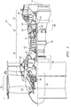
- FIG. 1 schematically illustrates a gas turbine engine 20.
- the gas turbine engine 20 as disclosed herein is a two spool turbofan that generally incorporates a fan section 22, a compressor section 24, a combustor section 26, and a turbine section 28.
- the fan section 22 drives air along a bypass flowpath while the compressor section 24 drives air along a core flowpath for compression and communication into the combustor section 26, then expansion through the turbine section 28.
- FIG. 1 schematically illustrates a gas turbine engine 20.
- the gas turbine engine 20 as disclosed herein is a two
- the engine 20 generally includes a low spool 30 and a high spool 32 mounted for rotation around an engine central longitudinal axis A relative to an engine case structure 36 via several bearings 38.
- the low spool 30 generally includes an inner shaft 40 that interconnects a fan 42, a Low Pressure Compressor (“LPC”) 44 and a Low Pressure Turbine (“LPT”) 46.
- the inner shaft 40 drives the fan 42 directly or through a geared architecture 48 to drive the fan 42 at a lower speed than the low spool 30.
- An exemplary reduction transmission is an epicyclic transmission, namely a planetary or star gear system.
- the high spool 32 includes an outer shaft 50 that interconnects a High Pressure Compressor (“HPC”) 52 and High Pressure Turbine (“HPT”) 54.
- a combustor 56 is arranged between the HPC 52 and the HPT 54.
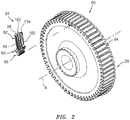
- a rotor assembly 60 such as a turbine rotor assembly includes an array of blades 84 (one shown) circumferentially disposed around a disk 86.
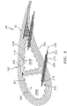
- Each blade 84 includes a root 88, a platform 90 and an airfoil 92.
- the blade root 88 is received within a rim 94 of the disk 86 and the airfoil 92 extends therefrom.
- the platform 90 separates a gas path side inclusive of the airfoil 92 and a non-gas path side inclusive of the root 88.
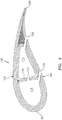
- the airfoil 92 defines a blade chord between a leading edge 98, which may include various forward and/or aft sweep configurations, and a trailing edge 100.
- a first sidewall 102 that may be convex to define a suction side, and a second sidewall 104 that may be concave to define a pressure side are joined at the leading edge 98 and at the axially spaced trailing edge 100.
- the tip 96 extends between the sidewalls 102, 104 opposite the platform 90.
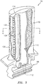
- each blade 84 includes an array of internal passageways 110.
- the array of internal passageways 110 includes a multiple of feed passages 112 through the root 88 that communicates airflow into a multiple of cavities 114 (shown schematically) within the airfoil 92.
- the cavities 114 distribute the cooling flow through passages 130 in the sidewalls 102, 104, leading edge 98, and/or the trailing edge 100 (also shown in FIG. 4 ).
- Impingement passages 132 may also be located though internal walls 134 between one or more of the array of internal passageways 110. It should be appreciated that various feed architectures, cavities, and passageway arrangements will benefit herefrom.
- the example cooled turbine airfoil 84 is manufactured as a CMC component. Though the CMC may have less strength relative to metallic counterparts, CMCs can endure higher material temperatures and are significantly lighter. Although a turbine blade will be used to illustrate the disclosed cooling passage formation method, other components will also benefit herefrom.
- the example turbine airfoil 84 is generally formed from a core 200 which may be formed from multiple portions 200A, 200B which are wrapped with a ceramic material 202.
- the core 200 is later removed such that the cured ceramic material 202 forms the airfoil 92 and the array of internal passageways 110.
- the core 200 may comprise a material such as carbon.
- the core 200 is readily cast and/or machined with conventional methods then later removed without damage to the ceramic material 202.
- the core 200 may include a multiple of longitudinal grooves 201.
- the ceramic material 202 may be an arrangement of ceramic fibers 204. Examples of the ceramic material 202 may include a three-dimensional weave of the ceramic fibers 204. Alternatively, or in addition, the ceramic material 202 may include a two-dimensional weave of the ceramic fibers 204. The ceramic material 202 may include multiple layers of two-dimensional weave of the ceramic fibers 204. Alternatively, or in addition, the ceramic material 202 may include a fiber layup, such as a unidirectional layup. In some examples, each of the ceramic fibers 204 may be a bundle and/or a tow of ceramic fibers. The fibers in each bundle or tow may be braided or otherwise arranged. The ceramic fibers 204 may comprise a material that is stable at temperatures above 1000 degrees Celsius. Examples of the ceramic fibers 204 may include fibers of alumina, mullite, silicon carbide, silicon, zirconia or carbon.
- a method 300 for forming the passages 130 through, for example, the airfoil sidewall 102, 104 ( FIG. 4 ) in a ceramic matrix composite component is illustrated in a schematic block diagram form. It should also be appreciated that application is not limited to aerospace components and various other applications will benefit herefrom.
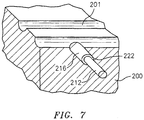
- a counterbored hole 212/216 ( FIG. 7 ) is drilled (304; FIG. 6 ) at each location in which the passages 130 are to be formed.
- the counterbored hole 212/216 includes a blind hole 212 for a rod 214 within a blind hole 216 for a hollow member 218 along a common axis 220 ( FIG. 5 ).
- a step 222 is formed between the blind holes 212, 216 to form a stop for the hollow member 218.
- Each counterbored hole 212/216 is located and oriented to form the respective passages 130.
- the hollow member 218 is located in each blind hole 216 (306, FIG. 6 ; FIG. 8 ).
- the hollow member 218 has an interior diameter equal to or greater to the size of the desired passage 130.
- the outside diameter may be equal to or slightly smaller than the blind hole 216.
- the hollow member 218 may include a sharp end 219 to form a hollow needle and may be manufactured of a metal alloy, a nylon, or any other rigid material that is compatible with the CMC material.
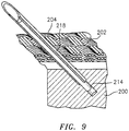
- the core 200 is wrapped with the ceramic material 202 using the hollow member 218 to pierce through the ceramic material 202 (308, FIG. 6 ; FIG. 9 ).
- the ceramic material 202 comprises the plurality of fibers 204 through which the hollow member 218 extends but does not cut.
- the hollow members 218 are of a strength to penetrate and separate the plurality of fibers 204.
- the core 200 is wrapped with the ceramic material 202 to form a ceramic matrix composite body that may be the CMC component in which the passage 130 is to be formed.
- the ceramic matrix composite body may be a component of the CMC component in which the passage 130 is to be formed.
- the ceramic matrix composite body may comprise of, for example, a silicon carbide ceramic matrix composite.
- the ceramic matrix composite body may have any shape or form, not just the shape illustrated.
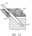
- the rod 214 is shaped and sized to form the desired passages 130.
- the rod 214 may be formed of the same material as the core such as a carbon.
- the rod 214 may be circular, rectilinear, oval, racetrack, or of other cross-sectional shape.
- each rod 214 may be glued into each blind hole 212 with a glue 223.
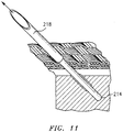
- the hollow member 218 is removed (312, FIG. 6 ; FIG. 11 ) leaving the rod 214 in place.
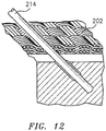
- the ceramic material 202 then closes ( FIG. 12 ) around the rod 214.
- the ceramic fibers 204 of the ceramic material 202 are not broken in this process, such that it is readily apparent that this method was used because any drilling method would result in the cutting of the ceramic fibers 204.
- the hollow member 218 can be manufactured of a material such as a nylon which can be readily burned out with the core 200 and then the rod 214 is burned out so that the hollow member need not be removed. That is, the hollow member 218 burns out at a lower temperature than infiltration temps then the rod 214 burns out with the core 200.
- the ceramic material 202 is cured (314, FIG. 6 ) per conventional CMC manufacturing procedures to form the CMC component.
- Forming the cooled turbine airfoil 84 as the CMC component may include infiltrating a molten metal or alloy into the ceramic material 202.
- the multiple of longitudinal grooves 201 ( FIG. 7 ) facilitate the infiltration.
- the molten metal or alloy fills the gaps between the ceramic fibers 204 and the rods 214.
- the molten metal or alloy may also react with a reactive element source present in the ceramic material 202 to form the ceramic matrix material.
- a chemical vapor infiltration coating may be applied to the ceramic material 202 prior to the melt infiltration to stiffen the ceramic fibers 204.
- forming the CMC component from the ceramic material 202 may include chemical vapor infiltrating the ceramic material 202 instead of melt infiltrating.
- the core 200 and rods 214 are removed (316, FIG. 6 ) via heat, acid, or other method which does not harm the ceramic material 202 per conventional CMC manufacturing procedures. Once the core 200 and rods 214 are removed, the passages 130 and the array of internal passageways 114 are formed.
- the "cast in" passages 130 are readily identifiable, may be of various cross-sectional shapes, reduce machining time, and facilitate the manufacture of long passages through CMC components such as those through the trailing edge of an airfoil.
Landscapes
- Engineering & Computer Science (AREA)
- Chemical & Material Sciences (AREA)
- Mechanical Engineering (AREA)
- General Engineering & Computer Science (AREA)
- Ceramic Engineering (AREA)
- Materials Engineering (AREA)
- Manufacturing & Machinery (AREA)
- Combustion & Propulsion (AREA)
- Composite Materials (AREA)
- Architecture (AREA)
- Turbine Rotor Nozzle Sealing (AREA)
- Manufacture Of Alloys Or Alloy Compounds (AREA)
Description
- The present disclosure relates to ceramic matrix composite components, and more particularly, to a cooling passage therein.
- Gas turbine engines typically include a compressor section to pressurize airflow, a combustor section to burn a hydrocarbon fuel in the presence of the pressurized air, and a turbine section to extract energy from the resultant combustion gases. Gas path components, such as turbine blades, often include airfoil cooling that may be accomplished by external film cooling, internal air impingement, and forced convection, either separately, or in combination.
- Ceramic matrix composite (CMC) components can endure high temperatures, but those temperatures may be below the gas path operational temperatures of some modern turbine engine stages. Internal convective cooling of CMC components may be primarily from impingement baffle like structures and film cooling from cooling passages. The cooling passages are either drilled using laser or Electron Discharge Machining (EDM). Laser passages are ideal for relatively short passages such as those at the leading edge of an airfoil, while EDM is ideal for long passages such as those at the trailing edge. EDM relies on a current supplied to an electrode which is discharged through a grounded part, however CMC material cannot carry current, and cannot use EDM. Machining cooling passages in the CMC component may result in cut fibers in the CMC material which may weaken the CMC component or expose a surface to environmental attacks.
-
US 2017/328217 A1 discloses prior art ceramic matrix composite airfoil cooling. -
US 2008/203236 A1 discloses a prior art CMC airfoil with a thin trailing edge. -
US2016/348515 discloses a method to form a hole in a ceramic matrix composite component, the method comprising: inserting a monolithic rod into a porous ceramic preform comprising a plurality of ceramic fibers; forming the ceramic preform into a ceramic matrix composite body, the ceramic matrix composite body including the monolithic rod; and removing a first portion of the monolithic rod, wherein a second portion of the monolithic rod remaining in the ceramic matrix composite body after the first portion is removed includes walls that define an opening in the ceramic matrix composite body. The component is an airfoil. - From one aspect, there is provided a method for forming a passage in a ceramic matrix composite component as recited in claim 1.
- In an embodiment, the ceramic material includes a plurality of fibers through which the hollow member extends but does not cut.
- Another embodiment includes separating a plurality of fibers around the hollow member.
- Another embodiment of any of the above includes penetrating the ceramic material with the hollow member.
- In another embodiment of any of the above, the rod is manufactured of the same material as the core.
- In another embodiment of any of the above, the rod is of a desired cooling passage shape.
- In another embodiment of any of the above, the hollow member includes a sharpened end.
- In another embodiment of any of the above, the hollow member is a needle.
- In another embodiment of any of the above, an inner surface of hollow member is sized to receive the rod.
- In another embodiment of any of the above, the hollow member is manufactured of metal.
- Another embodiment of any of the above includes coaxially forming a blind hole in the core for the rod within a blind hole in the core for the hollow member.
- Another embodiment of any of the above includes gluing the rod into the blind hole.
- Another embodiment of any of the above includes removing the hollow member and leaving the rod in the core.
- Another embodiment of any of the above includes removing the core and the rod from the ceramic material.
- Another embodiment of any of the above includes burning out the core and the rod from the ceramic material.
- Another embodiment of any of the above includes forming the hollow member of a nylon.
- Another embodiment of any of the above includes burning out the core, the hollow member, and the rod from the ceramic material.
- These features and elements as well as the operation thereof will become more apparent in light of the following description and the accompanying drawings. It should be understood, however, the following description and drawings are intended to be exemplary in nature and non-limiting.
- Various features will become apparent to those skilled in the art from the following detailed description of the disclosed non-limiting embodiment. The drawings that accompany the detailed description can be briefly described as follows:
-
FIG. 1 is a schematic cross-section of an example gas turbine engine architecture; -
FIG. 2 is an exploded view of rotor assembly with a single representative ceramic matrix composite turbine blade; -
FIG. 3 is a cross-sectional illustration of an example ceramic matrix composite turbine blade of the gas turbine engine. -
FIG. 4 is a cross-sectional illustration of an example ceramic matrix composite turbine blade taken along line 4-4 inFIG. 3 . -
FIG. 5 is a cross-sectional illustration of an example ceramic matrix composite turbine blade taken along line 4-4 inFIG. 3 illustrating formation of a passage in the ceramic matrix composite component according to one disclosed non-limiting embodiment. -
FIG. 6 illustrates a flow diagram of an example method to form a passage in the ceramic matrix composite component according to one disclosed non-limiting embodiment. -
FIG. 7 illustrates a cross-sectional view of a core for a ceramic matrix composite component illustrating a step of the method ofFIG. 6 illustrating drilling a counterbored hole. -
FIG. 8 illustrates a cross-sectional view of a core for a ceramic matrix composite component illustrating a step of the method ofFIG. 6 illustrating embedding a hollow member into the core. -
FIG. 9 illustrates a cross-sectional view of a core for a ceramic matrix composite component illustrating a step of the method ofFIG. 6 illustrating wrapping with a ceramic material such that the hollow member penetrates therethrough. -
FIG. 10 illustrates a cross-sectional view of a core for a ceramic matrix composite component illustrating a step of the method ofFIG. 6 illustrating inserting a rod into the hollow member. -
FIG. 11 illustrates a cross-sectional view of a core for a ceramic matrix composite component illustrating a step of the method ofFIG. 6 illustrating removing the hollow member. -
FIG. 12 illustrates a cross-sectional view of a core for a ceramic matrix composite component illustrating a step of the method ofFIG. 6 illustrating the ceramic material closing around the rod. -
FIG. 1 schematically illustrates agas turbine engine 20. Thegas turbine engine 20 as disclosed herein is a two spool turbofan that generally incorporates afan section 22, acompressor section 24, acombustor section 26, and aturbine section 28. Thefan section 22 drives air along a bypass flowpath while thecompressor section 24 drives air along a core flowpath for compression and communication into thecombustor section 26, then expansion through theturbine section 28. Although depicted as a high bypass gas turbofan engine architecture in the disclosed non-limiting embodiment, it should be appreciated that the concepts described herein are not limited only thereto. - The
engine 20 generally includes alow spool 30 and ahigh spool 32 mounted for rotation around an engine central longitudinal axis A relative to anengine case structure 36 viaseveral bearings 38. Thelow spool 30 generally includes aninner shaft 40 that interconnects afan 42, a Low Pressure Compressor ("LPC") 44 and a Low Pressure Turbine ("LPT") 46. Theinner shaft 40 drives thefan 42 directly or through a gearedarchitecture 48 to drive thefan 42 at a lower speed than thelow spool 30. An exemplary reduction transmission is an epicyclic transmission, namely a planetary or star gear system. Thehigh spool 32 includes anouter shaft 50 that interconnects a High Pressure Compressor ("HPC") 52 and High Pressure Turbine ("HPT") 54. Acombustor 56 is arranged between the HPC 52 and the HPT 54. - With reference to
FIG. 2 , arotor assembly 60 such as a turbine rotor assembly includes an array of blades 84 (one shown) circumferentially disposed around adisk 86. Eachblade 84 includes aroot 88, aplatform 90 and anairfoil 92. Theblade root 88 is received within arim 94 of thedisk 86 and theairfoil 92 extends therefrom. - The
platform 90 separates a gas path side inclusive of theairfoil 92 and a non-gas path side inclusive of theroot 88. Theairfoil 92 defines a blade chord between a leadingedge 98, which may include various forward and/or aft sweep configurations, and atrailing edge 100. Afirst sidewall 102 that may be convex to define a suction side, and asecond sidewall 104 that may be concave to define a pressure side are joined at theleading edge 98 and at the axially spaced trailingedge 100. Thetip 96 extends between thesidewalls platform 90. - With reference to
FIG. 3 , to resist the high temperature stress environment in the gas path of a turbine engine, eachblade 84 includes an array ofinternal passageways 110. The array ofinternal passageways 110 includes a multiple offeed passages 112 through theroot 88 that communicates airflow into a multiple of cavities 114 (shown schematically) within theairfoil 92. Thecavities 114 distribute the cooling flow throughpassages 130 in thesidewalls edge 98, and/or the trailing edge 100 (also shown inFIG. 4 ). Impingement passages 132 (FIG.4 ) may also be located thoughinternal walls 134 between one or more of the array ofinternal passageways 110. It should be appreciated that various feed architectures, cavities, and passageway arrangements will benefit herefrom. - With reference to
FIG.5 , the example cooledturbine airfoil 84 is manufactured as a CMC component. Though the CMC may have less strength relative to metallic counterparts, CMCs can endure higher material temperatures and are significantly lighter. Although a turbine blade will be used to illustrate the disclosed cooling passage formation method, other components will also benefit herefrom. - The
example turbine airfoil 84 is generally formed from acore 200 which may be formed frommultiple portions ceramic material 202. Thecore 200 is later removed such that the curedceramic material 202 forms theairfoil 92 and the array ofinternal passageways 110. Thecore 200 may comprise a material such as carbon. Thecore 200 is readily cast and/or machined with conventional methods then later removed without damage to theceramic material 202. Thecore 200 may include a multiple oflongitudinal grooves 201. - The
ceramic material 202 may be an arrangement ofceramic fibers 204. Examples of theceramic material 202 may include a three-dimensional weave of theceramic fibers 204. Alternatively, or in addition, theceramic material 202 may include a two-dimensional weave of theceramic fibers 204. Theceramic material 202 may include multiple layers of two-dimensional weave of theceramic fibers 204. Alternatively, or in addition, theceramic material 202 may include a fiber layup, such as a unidirectional layup. In some examples, each of theceramic fibers 204 may be a bundle and/or a tow of ceramic fibers. The fibers in each bundle or tow may be braided or otherwise arranged. Theceramic fibers 204 may comprise a material that is stable at temperatures above 1000 degrees Celsius. Examples of theceramic fibers 204 may include fibers of alumina, mullite, silicon carbide, silicon, zirconia or carbon. - With reference to
FIG. 6 , amethod 300 for forming thepassages 130 through, for example, theairfoil sidewall 102, 104 (FIG. 4 ) in a ceramic matrix composite component is illustrated in a schematic block diagram form. It should also be appreciated that application is not limited to aerospace components and various other applications will benefit herefrom. - Once the
core 200 is manufactured (302), acounterbored hole 212/216 (FIG. 7 ) is drilled (304;FIG. 6 ) at each location in which thepassages 130 are to be formed. Thecounterbored hole 212/216 includes ablind hole 212 for arod 214 within ablind hole 216 for ahollow member 218 along a common axis 220 (FIG. 5 ). Astep 222 is formed between theblind holes hollow member 218. Eachcounterbored hole 212/216 is located and oriented to form therespective passages 130. - Next, the
hollow member 218 is located in each blind hole 216 (306,FIG. 6 ;FIG. 8 ). Thehollow member 218 has an interior diameter equal to or greater to the size of the desiredpassage 130. The outside diameter may be equal to or slightly smaller than theblind hole 216. Thehollow member 218 may include asharp end 219 to form a hollow needle and may be manufactured of a metal alloy, a nylon, or any other rigid material that is compatible with the CMC material. - Next, the
core 200 is wrapped with theceramic material 202 using thehollow member 218 to pierce through the ceramic material 202 (308,FIG. 6 ;FIG. 9 ). Theceramic material 202 comprises the plurality offibers 204 through which thehollow member 218 extends but does not cut. Thehollow members 218 are of a strength to penetrate and separate the plurality offibers 204. - The
core 200 is wrapped with theceramic material 202 to form a ceramic matrix composite body that may be the CMC component in which thepassage 130 is to be formed. Alternatively, the ceramic matrix composite body may be a component of the CMC component in which thepassage 130 is to be formed. The ceramic matrix composite body may comprise of, for example, a silicon carbide ceramic matrix composite. The ceramic matrix composite body may have any shape or form, not just the shape illustrated. Once all the layers of theceramic material 202 are in place, onerod 214 is inserted into each hollow member 218 (310,FIG. 6 ;FIG. 10 ). - The
rod 214 is shaped and sized to form the desiredpassages 130. Therod 214 may be formed of the same material as the core such as a carbon. Therod 214 may be circular, rectilinear, oval, racetrack, or of other cross-sectional shape. Optionally, eachrod 214 may be glued into eachblind hole 212 with aglue 223. - Next, the
hollow member 218 is removed (312,FIG. 6 ;FIG. 11 ) leaving therod 214 in place. Theceramic material 202 then closes (FIG. 12 ) around therod 214. Theceramic fibers 204 of theceramic material 202 are not broken in this process, such that it is readily apparent that this method was used because any drilling method would result in the cutting of theceramic fibers 204. Alternatively, thehollow member 218 can be manufactured of a material such as a nylon which can be readily burned out with thecore 200 and then therod 214 is burned out so that the hollow member need not be removed. That is, thehollow member 218 burns out at a lower temperature than infiltration temps then therod 214 burns out with thecore 200. - Next, the
ceramic material 202 is cured (314,FIG. 6 ) per conventional CMC manufacturing procedures to form the CMC component. Forming the cooledturbine airfoil 84 as the CMC component may include infiltrating a molten metal or alloy into theceramic material 202. The multiple of longitudinal grooves 201 (FIG. 7 ) facilitate the infiltration. - The molten metal or alloy fills the gaps between the
ceramic fibers 204 and therods 214. The molten metal or alloy may also react with a reactive element source present in theceramic material 202 to form the ceramic matrix material. In some examples, a chemical vapor infiltration coating may be applied to theceramic material 202 prior to the melt infiltration to stiffen theceramic fibers 204. Alternatively, or in addition, forming the CMC component from theceramic material 202 may include chemical vapor infiltrating theceramic material 202 instead of melt infiltrating. - Finally, the
core 200 androds 214 are removed (316,FIG. 6 ) via heat, acid, or other method which does not harm theceramic material 202 per conventional CMC manufacturing procedures. Once thecore 200 androds 214 are removed, thepassages 130 and the array ofinternal passageways 114 are formed. - The "cast in"
passages 130 are readily identifiable, may be of various cross-sectional shapes, reduce machining time, and facilitate the manufacture of long passages through CMC components such as those through the trailing edge of an airfoil. - The use of the terms "a", "an", "the", and similar references in the context of description (especially in the context of the following claims) are to be construed to cover both the singular and the plural, unless otherwise indicated herein or specifically contradicted by context. The modifier "about" used in connection with a quantity is inclusive of the stated value and has the meaning dictated by the context (e.g., it includes the degree of error associated with measurement of the particular quantity). All ranges disclosed herein are inclusive of the endpoints, and the endpoints are independently combinable with each other.
- Although the different non-limiting embodiments have specific illustrated components, the embodiments of this invention are not limited to those particular combinations.
- It should be appreciated that like reference numerals identify corresponding or similar elements throughout the several drawings. It should also be appreciated that although a particular component arrangement is disclosed in the illustrated embodiment, other arrangements will benefit herefrom.
Claims (15)
- A method for forming a passage (130) in a ceramic matrix composite component (84), the method comprising:forming a core (200) for a ceramic matrix composite component (84);embedding a hollow member (218) into the core (200) at a desired location to form a passage (130) in the ceramic matrix composite component (84);wrapping the core (200) with a ceramic material (202); andinserting a rod (214) through the hollow member (218) and into the core (200).
- The method as recited in claim 1, wherein the ceramic material (202) comprises a plurality of fibers (204) through which the hollow member (218) extends but does not cut.
- The method as recited in claim 1 or 2, wherein wrapping the core (200) with the ceramic material (202) comprises separating a or the plurality of fibers (204) around the hollow member (218).
- The method as recited in any preceding claim, wherein wrapping the core (200) with the ceramic material (202) comprises penetrating the ceramic material (202) with the hollow member (218).
- The method as recited in any preceding claim, wherein the rod (214) is manufactured of the same material as the core (200).
- The method as recited in any preceding claim, wherein the rod (214) is of a desired cooling passage shape.
- The method as recited in any preceding claim, wherein the hollow member (218) comprises a sharpened end (219).
- The method as recited in any preceding claim, wherein the hollow member (218) is a needle.
- The method as recited in any preceding claim, wherein an inner surface of the hollow member (218) is sized to receive the rod (214).
- The method as recited in any preceding claim, further comprising coaxially forming a first blind hole (212) in the core (200) for the rod (214) within a second blind hole (216) in the core (200) for the hollow member (218).
- The method as recited in any preceding claim, further comprising gluing the rod (214) into a or the first blind hole (212) in the core (200).
- The method as recited in any preceding claim, further comprising removing the hollow member (218) and leaving the rod (214) in the core (200).
- The method as recited in claim 12, further comprising removing or burning out the core (200) and the rod (214) from the ceramic material (202).
- The method as recited in any preceding claim, wherein the hollow member (218) is manufactured of metal.
- The method as recited in any of claims 1 to 12, further comprising forming the hollow member (218) of a nylon, and optionally burning out the core (200), the hollow member (218), and the rod (214) from the ceramic material (202).
Priority Applications (1)
| Application Number | Priority Date | Filing Date | Title |
|---|---|---|---|
| EP21160277.6A EP3858568A1 (en) | 2018-01-05 | 2019-01-07 | Needled ceramic matrix composite cooling passages |
Applications Claiming Priority (1)
| Application Number | Priority Date | Filing Date | Title |
|---|---|---|---|
| US15/863,158 US11125087B2 (en) | 2018-01-05 | 2018-01-05 | Needled ceramic matrix composite cooling passages |
Related Child Applications (1)
| Application Number | Title | Priority Date | Filing Date |
|---|---|---|---|
| EP21160277.6A Division EP3858568A1 (en) | 2018-01-05 | 2019-01-07 | Needled ceramic matrix composite cooling passages |
Publications (3)
| Publication Number | Publication Date |
|---|---|
| EP3508317A2 EP3508317A2 (en) | 2019-07-10 |
| EP3508317A3 EP3508317A3 (en) | 2019-10-23 |
| EP3508317B1 true EP3508317B1 (en) | 2021-03-03 |
Family
ID=65003317
Family Applications (2)
| Application Number | Title | Priority Date | Filing Date |
|---|---|---|---|
| EP19150605.4A Active EP3508317B1 (en) | 2018-01-05 | 2019-01-07 | Method for making needled ceramic matrix composite cooling passages |
| EP21160277.6A Pending EP3858568A1 (en) | 2018-01-05 | 2019-01-07 | Needled ceramic matrix composite cooling passages |
Family Applications After (1)
| Application Number | Title | Priority Date | Filing Date |
|---|---|---|---|
| EP21160277.6A Pending EP3858568A1 (en) | 2018-01-05 | 2019-01-07 | Needled ceramic matrix composite cooling passages |
Country Status (2)
| Country | Link |
|---|---|
| US (2) | US11125087B2 (en) |
| EP (2) | EP3508317B1 (en) |
Families Citing this family (7)
| Publication number | Priority date | Publication date | Assignee | Title |
|---|---|---|---|---|
| US11098608B2 (en) * | 2019-03-13 | 2021-08-24 | Raytheon Technologies Corporation | CMC BOAS with internal support structure |
| WO2021034327A1 (en) * | 2019-08-22 | 2021-02-25 | Siemens Energy Global GmbH & Co. KG | Three-dimensional ceramic matrix composite t-joint for airfoils via pin-weaving |
| US20210108517A1 (en) * | 2019-10-15 | 2021-04-15 | United Technologies Corporation | Cmc airfoil with cooling holes |
| US11624287B2 (en) | 2020-02-21 | 2023-04-11 | Raytheon Technologies Corporation | Ceramic matrix composite component having low density core and method of making |
| US12077288B2 (en) * | 2021-02-19 | 2024-09-03 | Rtx Corporation | Bifurcating layup for airfoil rib, methods of manufacture thereof and articles comprising the same |
| US12157708B2 (en) * | 2021-05-07 | 2024-12-03 | Rtx Corporation | Method for creating cooling holes in a CMC laminate |
| US12240144B2 (en) * | 2023-04-14 | 2025-03-04 | Rtx Corporation | Method for CMC airfoil using core tube of rigidized ceramic fabric |
Family Cites Families (22)
| Publication number | Priority date | Publication date | Assignee | Title |
|---|---|---|---|---|
| US5186776A (en) * | 1990-05-07 | 1993-02-16 | Foster-Miller, Inc. | Composite laminate translaminar reinforcement apparatus and method |
| US6627019B2 (en) | 2000-12-18 | 2003-09-30 | David C. Jarmon | Process for making ceramic matrix composite parts with cooling channels |
| US6746755B2 (en) | 2001-09-24 | 2004-06-08 | Siemens Westinghouse Power Corporation | Ceramic matrix composite structure having integral cooling passages and method of manufacture |
| US7247003B2 (en) | 2004-12-02 | 2007-07-24 | Siemens Power Generation, Inc. | Stacked lamellate assembly |
| US7153096B2 (en) | 2004-12-02 | 2006-12-26 | Siemens Power Generation, Inc. | Stacked laminate CMC turbine vane |
| DE102005024408A1 (en) * | 2005-05-27 | 2006-11-30 | Airbus Deutschland Gmbh | Producing fiber reinforced foam materials for aircraft involves engaging through hole from first surface to engage at least one fiber bundle and pulling bundle(s) into through hole in foam material |
| US7600978B2 (en) | 2006-07-27 | 2009-10-13 | Siemens Energy, Inc. | Hollow CMC airfoil with internal stitch |
| US20080199661A1 (en) | 2007-02-15 | 2008-08-21 | Siemens Power Generation, Inc. | Thermally insulated CMC structure with internal cooling |
| US7887300B2 (en) | 2007-02-27 | 2011-02-15 | Siemens Energy, Inc. | CMC airfoil with thin trailing edge |
| FR2924426B1 (en) | 2007-11-30 | 2011-06-03 | Messier Bugatti | PROCESS FOR MANUFACTURING COMPOSITE MATERIAL PARTS WITH CARBON FIBER REINFORCEMENT |
| US8202588B2 (en) | 2008-04-08 | 2012-06-19 | Siemens Energy, Inc. | Hybrid ceramic structure with internal cooling arrangements |
| US8292580B2 (en) | 2008-09-18 | 2012-10-23 | Siemens Energy, Inc. | CMC vane assembly apparatus and method |
| US9161461B2 (en) | 2012-06-14 | 2015-10-13 | Zhuhai Advanced Chip Carriers & Electronic Substrate Solutions Technologies Co. Ltd. | Multilayer electronic structure with stepped holes |
| US20140093392A1 (en) | 2012-10-03 | 2014-04-03 | Rolls-Royce Plc | Gas turbine engine component |
| CA2913031C (en) | 2013-05-29 | 2021-09-21 | General Electric Company | Method of forming a ceramic matrix composite component with cooling features |
| US9664053B2 (en) * | 2014-02-12 | 2017-05-30 | Teledyne Scientific & Imaging, Llc | Integral textile structure for 3-D CMC turbine airfoils |
| US10563522B2 (en) | 2014-09-22 | 2020-02-18 | Rolls-Royce North American Technologies Inc. | Composite airfoil for a gas turbine engine |
| EP3059390B1 (en) | 2015-02-18 | 2020-03-04 | Rolls-Royce Corporation | Vane assembly for a gas turbine engine, airfoil and method of making |
| US10024175B2 (en) * | 2015-05-26 | 2018-07-17 | Rolls-Royce Corporation | Cooling holes manufactured with EBC in place |
| US9797263B2 (en) * | 2015-05-26 | 2017-10-24 | Rolls-Royce Corporation | Monolithic ceramic rods to enable cooling holes in CMC |
| US10605095B2 (en) | 2016-05-11 | 2020-03-31 | General Electric Company | Ceramic matrix composite airfoil cooling |
| US10774005B2 (en) * | 2018-01-05 | 2020-09-15 | Raytheon Technologies Corporation | Needled ceramic matrix composite cooling passages |
-
2018
- 2018-01-05 US US15/863,158 patent/US11125087B2/en active Active
-
2019
- 2019-01-07 EP EP19150605.4A patent/EP3508317B1/en active Active
- 2019-01-07 EP EP21160277.6A patent/EP3858568A1/en active Pending
-
2021
- 2021-08-18 US US17/405,327 patent/US20210381387A1/en active Pending
Non-Patent Citations (1)
| Title |
|---|
| None * |
Also Published As
| Publication number | Publication date |
|---|---|
| US20210381387A1 (en) | 2021-12-09 |
| EP3508317A2 (en) | 2019-07-10 |
| EP3858568A1 (en) | 2021-08-04 |
| EP3508317A3 (en) | 2019-10-23 |
| US20190211695A1 (en) | 2019-07-11 |
| US11125087B2 (en) | 2021-09-21 |
Similar Documents
| Publication | Publication Date | Title |
|---|---|---|
| US12570580B2 (en) | Needled ceramic matrix composite cooling passages | |
| EP3508317B1 (en) | Method for making needled ceramic matrix composite cooling passages | |
| CN109196186B (en) | Ceramic Matrix Composite Airfoil Cooling | |
| US9975176B2 (en) | Method and assembly for forming components having internal passages using a lattice structure | |
| US9138804B2 (en) | Core for a casting process | |
| CN109072701B (en) | Ceramic Matrix Composite Airfoil Cooling | |
| WO2015069411A1 (en) | Gas turbine engine turbine blade tip cooling | |
| EP3044418B1 (en) | Gas turbine engine airfoil with wishbone baffle cooling scheme | |
| EP3757352B1 (en) | Method for forming an airfoil with internal cavities | |
| EP3323612B1 (en) | Method for making ceramic turbine engine article | |
| EP3865663A1 (en) | Extended root region and platform over-wrap for a blade of a gas turbine engine | |
| EP3751103B1 (en) | Ceramic matrix composite rotor blade attachment | |
| GB2606342A (en) | Fibre reinforced gas turbine engine component | |
| US12078081B1 (en) | Airfoil with CMC ply cutouts for cooling channels | |
| EP3757351B1 (en) | Method for manufacturing an airfoil | |
| US20250116197A1 (en) | Cmc airfoil with circumventing cooling passage | |
| EP3287601B1 (en) | Multi-piece non-linear fan blade | |
| EP3705201B1 (en) | Component for a gas turbine engine | |
| EP3412868A1 (en) | Adjustable flow split platform cooling for gas turbine engine | |
| EP3663520B1 (en) | Composite fan blade with leading edge sheath | |
| EP3808940B1 (en) | Cmc airfoil for a gas turbine engine with cooling holes | |
| EP3415716B1 (en) | Blade tip cooling |
Legal Events
| Date | Code | Title | Description |
|---|---|---|---|
| PUAI | Public reference made under article 153(3) epc to a published international application that has entered the european phase |
Free format text: ORIGINAL CODE: 0009012 |
|
| STAA | Information on the status of an ep patent application or granted ep patent |
Free format text: STATUS: THE APPLICATION HAS BEEN PUBLISHED |
|
| AK | Designated contracting states |
Kind code of ref document: A2 Designated state(s): AL AT BE BG CH CY CZ DE DK EE ES FI FR GB GR HR HU IE IS IT LI LT LU LV MC MK MT NL NO PL PT RO RS SE SI SK SM TR |
|
| AX | Request for extension of the european patent |
Extension state: BA ME |
|
| PUAL | Search report despatched |
Free format text: ORIGINAL CODE: 0009013 |
|
| AK | Designated contracting states |
Kind code of ref document: A3 Designated state(s): AL AT BE BG CH CY CZ DE DK EE ES FI FR GB GR HR HU IE IS IT LI LT LU LV MC MK MT NL NO PL PT RO RS SE SI SK SM TR |
|
| AX | Request for extension of the european patent |
Extension state: BA ME |
|
| RIC1 | Information provided on ipc code assigned before grant |
Ipc: B32B 18/00 20060101ALI20190914BHEP Ipc: B28B 7/34 20060101ALI20190914BHEP Ipc: B28B 7/16 20060101AFI20190914BHEP Ipc: F01D 5/18 20060101ALI20190914BHEP Ipc: B28B 7/28 20060101ALI20190914BHEP |
|
| STAA | Information on the status of an ep patent application or granted ep patent |
Free format text: STATUS: REQUEST FOR EXAMINATION WAS MADE |
|
| 17P | Request for examination filed |
Effective date: 20200423 |
|
| RBV | Designated contracting states (corrected) |
Designated state(s): AL AT BE BG CH CY CZ DE DK EE ES FI FR GB GR HR HU IE IS IT LI LT LU LV MC MK MT NL NO PL PT RO RS SE SI SK SM TR |
|
| REG | Reference to a national code |
Ref country code: DE Ref legal event code: R079 Ref document number: 602019002811 Country of ref document: DE Free format text: PREVIOUS MAIN CLASS: B28B0007160000 Ipc: B28B0007340000 |
|
| GRAP | Despatch of communication of intention to grant a patent |
Free format text: ORIGINAL CODE: EPIDOSNIGR1 |
|
| STAA | Information on the status of an ep patent application or granted ep patent |
Free format text: STATUS: GRANT OF PATENT IS INTENDED |
|
| RIC1 | Information provided on ipc code assigned before grant |
Ipc: B28B 7/18 20060101ALI20200724BHEP Ipc: B28B 23/00 20060101ALI20200724BHEP Ipc: F23R 3/00 20060101ALI20200724BHEP Ipc: B32B 18/00 20060101ALI20200724BHEP Ipc: F01D 5/18 20060101ALI20200724BHEP Ipc: F01D 9/06 20060101ALI20200724BHEP Ipc: F23R 3/60 20060101ALI20200724BHEP Ipc: F23R 3/50 20060101ALI20200724BHEP Ipc: F01D 5/28 20060101ALI20200724BHEP Ipc: B28B 7/34 20060101AFI20200724BHEP |
|
| INTG | Intention to grant announced |
Effective date: 20200831 |
|
| GRAS | Grant fee paid |
Free format text: ORIGINAL CODE: EPIDOSNIGR3 |
|
| GRAA | (expected) grant |
Free format text: ORIGINAL CODE: 0009210 |
|
| STAA | Information on the status of an ep patent application or granted ep patent |
Free format text: STATUS: THE PATENT HAS BEEN GRANTED |
|
| AK | Designated contracting states |
Kind code of ref document: B1 Designated state(s): AL AT BE BG CH CY CZ DE DK EE ES FI FR GB GR HR HU IE IS IT LI LT LU LV MC MK MT NL NO PL PT RO RS SE SI SK SM TR |
|
| REG | Reference to a national code |
Ref country code: GB Ref legal event code: FG4D |
|
| REG | Reference to a national code |
Ref country code: DE Ref legal event code: R081 Ref document number: 602019002811 Country of ref document: DE Owner name: RAYTHEON TECHNOLOGIES CORPORATION, FARMINGTON, US Free format text: FORMER OWNER: UNITED TECHNOLOGIES CORPORATION, FARMINGTON, CONN., US Ref country code: DE Ref legal event code: R081 Ref document number: 602019002811 Country of ref document: DE Owner name: RTX CORPORATION (N.D.GES.D. STAATES DELAWARE),, US Free format text: FORMER OWNER: UNITED TECHNOLOGIES CORPORATION, FARMINGTON, CONN., US |
|
| REG | Reference to a national code |
Ref country code: CH Ref legal event code: EP Ref country code: AT Ref legal event code: REF Ref document number: 1366713 Country of ref document: AT Kind code of ref document: T Effective date: 20210315 |
|
| REG | Reference to a national code |
Ref country code: DE Ref legal event code: R096 Ref document number: 602019002811 Country of ref document: DE |
|
| RAP2 | Party data changed (patent owner data changed or rights of a patent transferred) |
Owner name: RAYTHEON TECHNOLOGIES CORPORATION |
|
| REG | Reference to a national code |
Ref country code: IE Ref legal event code: FG4D |
|
| REG | Reference to a national code |
Ref country code: LT Ref legal event code: MG9D |
|
| PG25 | Lapsed in a contracting state [announced via postgrant information from national office to epo] |
Ref country code: LT Free format text: LAPSE BECAUSE OF FAILURE TO SUBMIT A TRANSLATION OF THE DESCRIPTION OR TO PAY THE FEE WITHIN THE PRESCRIBED TIME-LIMIT Effective date: 20210303 Ref country code: NO Free format text: LAPSE BECAUSE OF FAILURE TO SUBMIT A TRANSLATION OF THE DESCRIPTION OR TO PAY THE FEE WITHIN THE PRESCRIBED TIME-LIMIT Effective date: 20210603 Ref country code: BG Free format text: LAPSE BECAUSE OF FAILURE TO SUBMIT A TRANSLATION OF THE DESCRIPTION OR TO PAY THE FEE WITHIN THE PRESCRIBED TIME-LIMIT Effective date: 20210603 Ref country code: HR Free format text: LAPSE BECAUSE OF FAILURE TO SUBMIT A TRANSLATION OF THE DESCRIPTION OR TO PAY THE FEE WITHIN THE PRESCRIBED TIME-LIMIT Effective date: 20210303 Ref country code: GR Free format text: LAPSE BECAUSE OF FAILURE TO SUBMIT A TRANSLATION OF THE DESCRIPTION OR TO PAY THE FEE WITHIN THE PRESCRIBED TIME-LIMIT Effective date: 20210604 Ref country code: FI Free format text: LAPSE BECAUSE OF FAILURE TO SUBMIT A TRANSLATION OF THE DESCRIPTION OR TO PAY THE FEE WITHIN THE PRESCRIBED TIME-LIMIT Effective date: 20210303 |
|
| REG | Reference to a national code |
Ref country code: NL Ref legal event code: MP Effective date: 20210303 |
|
| REG | Reference to a national code |
Ref country code: AT Ref legal event code: MK05 Ref document number: 1366713 Country of ref document: AT Kind code of ref document: T Effective date: 20210303 |
|
| PG25 | Lapsed in a contracting state [announced via postgrant information from national office to epo] |
Ref country code: SE Free format text: LAPSE BECAUSE OF FAILURE TO SUBMIT A TRANSLATION OF THE DESCRIPTION OR TO PAY THE FEE WITHIN THE PRESCRIBED TIME-LIMIT Effective date: 20210303 Ref country code: RS Free format text: LAPSE BECAUSE OF FAILURE TO SUBMIT A TRANSLATION OF THE DESCRIPTION OR TO PAY THE FEE WITHIN THE PRESCRIBED TIME-LIMIT Effective date: 20210303 Ref country code: PL Free format text: LAPSE BECAUSE OF FAILURE TO SUBMIT A TRANSLATION OF THE DESCRIPTION OR TO PAY THE FEE WITHIN THE PRESCRIBED TIME-LIMIT Effective date: 20210303 Ref country code: LV Free format text: LAPSE BECAUSE OF FAILURE TO SUBMIT A TRANSLATION OF THE DESCRIPTION OR TO PAY THE FEE WITHIN THE PRESCRIBED TIME-LIMIT Effective date: 20210303 |
|
| PG25 | Lapsed in a contracting state [announced via postgrant information from national office to epo] |
Ref country code: NL Free format text: LAPSE BECAUSE OF FAILURE TO SUBMIT A TRANSLATION OF THE DESCRIPTION OR TO PAY THE FEE WITHIN THE PRESCRIBED TIME-LIMIT Effective date: 20210303 |
|
| PG25 | Lapsed in a contracting state [announced via postgrant information from national office to epo] |
Ref country code: AT Free format text: LAPSE BECAUSE OF FAILURE TO SUBMIT A TRANSLATION OF THE DESCRIPTION OR TO PAY THE FEE WITHIN THE PRESCRIBED TIME-LIMIT Effective date: 20210303 Ref country code: SM Free format text: LAPSE BECAUSE OF FAILURE TO SUBMIT A TRANSLATION OF THE DESCRIPTION OR TO PAY THE FEE WITHIN THE PRESCRIBED TIME-LIMIT Effective date: 20210303 Ref country code: EE Free format text: LAPSE BECAUSE OF FAILURE TO SUBMIT A TRANSLATION OF THE DESCRIPTION OR TO PAY THE FEE WITHIN THE PRESCRIBED TIME-LIMIT Effective date: 20210303 Ref country code: CZ Free format text: LAPSE BECAUSE OF FAILURE TO SUBMIT A TRANSLATION OF THE DESCRIPTION OR TO PAY THE FEE WITHIN THE PRESCRIBED TIME-LIMIT Effective date: 20210303 |
|
| PG25 | Lapsed in a contracting state [announced via postgrant information from national office to epo] |
Ref country code: IS Free format text: LAPSE BECAUSE OF FAILURE TO SUBMIT A TRANSLATION OF THE DESCRIPTION OR TO PAY THE FEE WITHIN THE PRESCRIBED TIME-LIMIT Effective date: 20210703 Ref country code: RO Free format text: LAPSE BECAUSE OF FAILURE TO SUBMIT A TRANSLATION OF THE DESCRIPTION OR TO PAY THE FEE WITHIN THE PRESCRIBED TIME-LIMIT Effective date: 20210303 Ref country code: PT Free format text: LAPSE BECAUSE OF FAILURE TO SUBMIT A TRANSLATION OF THE DESCRIPTION OR TO PAY THE FEE WITHIN THE PRESCRIBED TIME-LIMIT Effective date: 20210705 Ref country code: SK Free format text: LAPSE BECAUSE OF FAILURE TO SUBMIT A TRANSLATION OF THE DESCRIPTION OR TO PAY THE FEE WITHIN THE PRESCRIBED TIME-LIMIT Effective date: 20210303 |
|
| REG | Reference to a national code |
Ref country code: DE Ref legal event code: R097 Ref document number: 602019002811 Country of ref document: DE |
|
| PLBE | No opposition filed within time limit |
Free format text: ORIGINAL CODE: 0009261 |
|
| STAA | Information on the status of an ep patent application or granted ep patent |
Free format text: STATUS: NO OPPOSITION FILED WITHIN TIME LIMIT |
|
| PG25 | Lapsed in a contracting state [announced via postgrant information from national office to epo] |
Ref country code: DK Free format text: LAPSE BECAUSE OF FAILURE TO SUBMIT A TRANSLATION OF THE DESCRIPTION OR TO PAY THE FEE WITHIN THE PRESCRIBED TIME-LIMIT Effective date: 20210303 Ref country code: AL Free format text: LAPSE BECAUSE OF FAILURE TO SUBMIT A TRANSLATION OF THE DESCRIPTION OR TO PAY THE FEE WITHIN THE PRESCRIBED TIME-LIMIT Effective date: 20210303 Ref country code: ES Free format text: LAPSE BECAUSE OF FAILURE TO SUBMIT A TRANSLATION OF THE DESCRIPTION OR TO PAY THE FEE WITHIN THE PRESCRIBED TIME-LIMIT Effective date: 20210303 |
|
| 26N | No opposition filed |
Effective date: 20211206 |
|
| PG25 | Lapsed in a contracting state [announced via postgrant information from national office to epo] |
Ref country code: SI Free format text: LAPSE BECAUSE OF FAILURE TO SUBMIT A TRANSLATION OF THE DESCRIPTION OR TO PAY THE FEE WITHIN THE PRESCRIBED TIME-LIMIT Effective date: 20210303 |
|
| PG25 | Lapsed in a contracting state [announced via postgrant information from national office to epo] |
Ref country code: IT Free format text: LAPSE BECAUSE OF FAILURE TO SUBMIT A TRANSLATION OF THE DESCRIPTION OR TO PAY THE FEE WITHIN THE PRESCRIBED TIME-LIMIT Effective date: 20210303 |
|
| PG25 | Lapsed in a contracting state [announced via postgrant information from national office to epo] |
Ref country code: IS Free format text: LAPSE BECAUSE OF FAILURE TO SUBMIT A TRANSLATION OF THE DESCRIPTION OR TO PAY THE FEE WITHIN THE PRESCRIBED TIME-LIMIT Effective date: 20210703 |
|
| PG25 | Lapsed in a contracting state [announced via postgrant information from national office to epo] |
Ref country code: MC Free format text: LAPSE BECAUSE OF FAILURE TO SUBMIT A TRANSLATION OF THE DESCRIPTION OR TO PAY THE FEE WITHIN THE PRESCRIBED TIME-LIMIT Effective date: 20210303 |
|
| REG | Reference to a national code |
Ref country code: CH Ref legal event code: PL |
|
| REG | Reference to a national code |
Ref country code: BE Ref legal event code: MM Effective date: 20220131 |
|
| PG25 | Lapsed in a contracting state [announced via postgrant information from national office to epo] |
Ref country code: LU Free format text: LAPSE BECAUSE OF NON-PAYMENT OF DUE FEES Effective date: 20220107 |
|
| PG25 | Lapsed in a contracting state [announced via postgrant information from national office to epo] |
Ref country code: BE Free format text: LAPSE BECAUSE OF NON-PAYMENT OF DUE FEES Effective date: 20220131 |
|
| PG25 | Lapsed in a contracting state [announced via postgrant information from national office to epo] |
Ref country code: LI Free format text: LAPSE BECAUSE OF NON-PAYMENT OF DUE FEES Effective date: 20220131 Ref country code: CH Free format text: LAPSE BECAUSE OF NON-PAYMENT OF DUE FEES Effective date: 20220131 |
|
| PG25 | Lapsed in a contracting state [announced via postgrant information from national office to epo] |
Ref country code: IE Free format text: LAPSE BECAUSE OF NON-PAYMENT OF DUE FEES Effective date: 20220107 |
|
| P01 | Opt-out of the competence of the unified patent court (upc) registered |
Effective date: 20230521 |
|
| PG25 | Lapsed in a contracting state [announced via postgrant information from national office to epo] |
Ref country code: HU Free format text: LAPSE BECAUSE OF FAILURE TO SUBMIT A TRANSLATION OF THE DESCRIPTION OR TO PAY THE FEE WITHIN THE PRESCRIBED TIME-LIMIT; INVALID AB INITIO Effective date: 20190107 |
|
| PG25 | Lapsed in a contracting state [announced via postgrant information from national office to epo] |
Ref country code: MK Free format text: LAPSE BECAUSE OF FAILURE TO SUBMIT A TRANSLATION OF THE DESCRIPTION OR TO PAY THE FEE WITHIN THE PRESCRIBED TIME-LIMIT Effective date: 20210303 Ref country code: CY Free format text: LAPSE BECAUSE OF FAILURE TO SUBMIT A TRANSLATION OF THE DESCRIPTION OR TO PAY THE FEE WITHIN THE PRESCRIBED TIME-LIMIT Effective date: 20210303 |
|
| PG25 | Lapsed in a contracting state [announced via postgrant information from national office to epo] |
Ref country code: TR Free format text: LAPSE BECAUSE OF FAILURE TO SUBMIT A TRANSLATION OF THE DESCRIPTION OR TO PAY THE FEE WITHIN THE PRESCRIBED TIME-LIMIT Effective date: 20210303 |
|
| PG25 | Lapsed in a contracting state [announced via postgrant information from national office to epo] |
Ref country code: MT Free format text: LAPSE BECAUSE OF FAILURE TO SUBMIT A TRANSLATION OF THE DESCRIPTION OR TO PAY THE FEE WITHIN THE PRESCRIBED TIME-LIMIT Effective date: 20210303 |
|
| REG | Reference to a national code |
Ref country code: DE Ref legal event code: R081 Ref document number: 602019002811 Country of ref document: DE Owner name: RTX CORPORATION (N.D.GES.D. STAATES DELAWARE),, US Free format text: FORMER OWNER: RAYTHEON TECHNOLOGIES CORPORATION, FARMINGTON, CT, US |
|
| PGFP | Annual fee paid to national office [announced via postgrant information from national office to epo] |
Ref country code: GB Payment date: 20251220 Year of fee payment: 8 |
|
| PGFP | Annual fee paid to national office [announced via postgrant information from national office to epo] |
Ref country code: FR Payment date: 20251217 Year of fee payment: 8 |
|
| PGFP | Annual fee paid to national office [announced via postgrant information from national office to epo] |
Ref country code: DE Payment date: 20251217 Year of fee payment: 8 |