EP3508288B1 - Hybride generative fertigung - Google Patents
Hybride generative fertigung Download PDFInfo
- Publication number
- EP3508288B1 EP3508288B1 EP19150769.8A EP19150769A EP3508288B1 EP 3508288 B1 EP3508288 B1 EP 3508288B1 EP 19150769 A EP19150769 A EP 19150769A EP 3508288 B1 EP3508288 B1 EP 3508288B1
- Authority
- EP
- European Patent Office
- Prior art keywords
- preform
- elevation
- metallic powder
- powder
- build platform
- Prior art date
- Legal status (The legal status is an assumption and is not a legal conclusion. Google has not performed a legal analysis and makes no representation as to the accuracy of the status listed.)
- Active
Links
Images

Classifications
-
- B—PERFORMING OPERATIONS; TRANSPORTING
- B22—CASTING; POWDER METALLURGY
- B22F—WORKING METALLIC POWDER; MANUFACTURE OF ARTICLES FROM METALLIC POWDER; MAKING METALLIC POWDER; APPARATUS OR DEVICES SPECIALLY ADAPTED FOR METALLIC POWDER
- B22F7/00—Manufacture of composite layers, workpieces, or articles, comprising metallic powder, by sintering the powder, with or without compacting wherein at least one part is obtained by sintering or compression
- B22F7/06—Manufacture of composite layers, workpieces, or articles, comprising metallic powder, by sintering the powder, with or without compacting wherein at least one part is obtained by sintering or compression of composite workpieces or articles from parts, e.g. to form tipped tools
- B22F7/08—Manufacture of composite layers, workpieces, or articles, comprising metallic powder, by sintering the powder, with or without compacting wherein at least one part is obtained by sintering or compression of composite workpieces or articles from parts, e.g. to form tipped tools with one or more parts not made from powder
-
- B—PERFORMING OPERATIONS; TRANSPORTING
- B22—CASTING; POWDER METALLURGY
- B22F—WORKING METALLIC POWDER; MANUFACTURE OF ARTICLES FROM METALLIC POWDER; MAKING METALLIC POWDER; APPARATUS OR DEVICES SPECIALLY ADAPTED FOR METALLIC POWDER
- B22F10/00—Additive manufacturing of workpieces or articles from metallic powder
- B22F10/20—Direct sintering or melting
- B22F10/28—Powder bed fusion, e.g. selective laser melting [SLM] or electron beam melting [EBM]
-
- B—PERFORMING OPERATIONS; TRANSPORTING
- B22—CASTING; POWDER METALLURGY
- B22F—WORKING METALLIC POWDER; MANUFACTURE OF ARTICLES FROM METALLIC POWDER; MAKING METALLIC POWDER; APPARATUS OR DEVICES SPECIALLY ADAPTED FOR METALLIC POWDER
- B22F12/00—Apparatus or devices specially adapted for additive manufacturing; Auxiliary means for additive manufacturing; Combinations of additive manufacturing apparatus or devices with other processing apparatus or devices
- B22F12/50—Means for feeding of material, e.g. heads
-
- B—PERFORMING OPERATIONS; TRANSPORTING
- B22—CASTING; POWDER METALLURGY
- B22F—WORKING METALLIC POWDER; MANUFACTURE OF ARTICLES FROM METALLIC POWDER; MAKING METALLIC POWDER; APPARATUS OR DEVICES SPECIALLY ADAPTED FOR METALLIC POWDER
- B22F7/00—Manufacture of composite layers, workpieces, or articles, comprising metallic powder, by sintering the powder, with or without compacting wherein at least one part is obtained by sintering or compression
- B22F7/02—Manufacture of composite layers, workpieces, or articles, comprising metallic powder, by sintering the powder, with or without compacting wherein at least one part is obtained by sintering or compression of composite layers
- B22F7/04—Manufacture of composite layers, workpieces, or articles, comprising metallic powder, by sintering the powder, with or without compacting wherein at least one part is obtained by sintering or compression of composite layers with one or more layers not made from powder, e.g. made from solid metal
-
- B—PERFORMING OPERATIONS; TRANSPORTING
- B33—ADDITIVE MANUFACTURING TECHNOLOGY
- B33Y—ADDITIVE MANUFACTURING, i.e. MANUFACTURING OF THREE-DIMENSIONAL [3D] OBJECTS BY ADDITIVE DEPOSITION, ADDITIVE AGGLOMERATION OR ADDITIVE LAYERING, e.g. BY 3D PRINTING, STEREOLITHOGRAPHY OR SELECTIVE LASER SINTERING
- B33Y10/00—Processes of additive manufacturing
-
- B—PERFORMING OPERATIONS; TRANSPORTING
- B33—ADDITIVE MANUFACTURING TECHNOLOGY
- B33Y—ADDITIVE MANUFACTURING, i.e. MANUFACTURING OF THREE-DIMENSIONAL [3D] OBJECTS BY ADDITIVE DEPOSITION, ADDITIVE AGGLOMERATION OR ADDITIVE LAYERING, e.g. BY 3D PRINTING, STEREOLITHOGRAPHY OR SELECTIVE LASER SINTERING
- B33Y30/00—Apparatus for additive manufacturing; Details thereof or accessories therefor
-
- B—PERFORMING OPERATIONS; TRANSPORTING
- B22—CASTING; POWDER METALLURGY
- B22F—WORKING METALLIC POWDER; MANUFACTURE OF ARTICLES FROM METALLIC POWDER; MAKING METALLIC POWDER; APPARATUS OR DEVICES SPECIALLY ADAPTED FOR METALLIC POWDER
- B22F2999/00—Aspects linked to processes or compositions used in powder metallurgy
-
- Y—GENERAL TAGGING OF NEW TECHNOLOGICAL DEVELOPMENTS; GENERAL TAGGING OF CROSS-SECTIONAL TECHNOLOGIES SPANNING OVER SEVERAL SECTIONS OF THE IPC; TECHNICAL SUBJECTS COVERED BY FORMER USPC CROSS-REFERENCE ART COLLECTIONS [XRACs] AND DIGESTS
- Y02—TECHNOLOGIES OR APPLICATIONS FOR MITIGATION OR ADAPTATION AGAINST CLIMATE CHANGE
- Y02P—CLIMATE CHANGE MITIGATION TECHNOLOGIES IN THE PRODUCTION OR PROCESSING OF GOODS
- Y02P10/00—Technologies related to metal processing
- Y02P10/25—Process efficiency
Definitions
- Additive manufacturing is a useful process for forming three-dimensional components by creating successive layers of material.
- metallic powder is spread along a build surface, and an energy source is used to rapidly and locally fuse the powder. The metal solidifies into successive layers that build up to form the desired part.
- a prior art additive manufacturing system having the features of the preamble of claim 1 is disclosed in US 2017/333994 A1 . Further prior art systems are provided in KR 2012 0063385 A , WO 2016/152012 A1 and US 2017/259329 A1 .
- an additive manufacturing system for fabricating a hybrid component is provided as set forth in claim 1.
- a method of fabricating a hybrid component is provided as set forth in claim 4.
- the present invention is directed to a system and method of fabricating a hybrid component using additive manufacturing.
- one or more preform structures are secured to a build platform, and successive layers of metallic powder are deposited over and/or around the preform by a powder deposition device positioned above the preform and build platform.
- the preform is designed to a desired specification, thus allowing for the fabrication of components with complex geometries and/or high-strength portions that would otherwise be difficult to form using a metal additive manufacturing process.
- FIGS. 1A and 1B are simplified illustrations of the claimed additive manufacturing system 10.
- System 10 includes build platform 12, preforms 14 and 16, metallic powder 18, powder distribution device 20, and energy source 22.
- Build platform 12 can be a generally planar structure and includes platform surface 24, upon which a component can be formed.
- Build platform 12 further includes first end 26 and an opposing second end 28.
- preform 14 is a hollow, cylindrical structure having an outer surface 30 and an inner surface 32.
- Preform 16 is a flanged structure having upper horizontal surface 34 and downward-facing surface 36. Surfaces 30 and 34, as shown, are higher than platform surface 24, and are generally capable of receiving metallic powder 18.
- Preforms 14 and 16 can be a metal or metal alloy formed using any traditional or additive manufacturing process known in the art as suitable for fabricating metal components. If necessary, preforms 14 and 16 can undergo secondary processing or finishing (e.g. milling, drilling, or polishing) to achieve desired features or surface finishes. For example, preform 14 can become a portion of a fluid passage, and thus it may be desirable for inner surface 32 to have a smooth finish.
- Preforms 14 and 16 can be secured to surface 24 of platform 12 using, for example, a welding or a brazing technique. Preforms 14 and 16 can alternatively be secured on or proximate to surface 24 using a fastening device, such as a clamp.
- Powder distribution device 20 is located at an elevation E above build platform 12 and the uppermost surfaces of preforms 14 and 16, which are outer surfaces 30 and 34, respectively.
- device 20 is a retractable conveyor belt configured to move over the build platform at elevation E, using a system of moving and fixed rollers. Specifically, device 20 can begin the position shown in FIG. 1A , and move from first end 26 to second end 28 distributing metallic powder 18 at predetermined locations on platform surface 24 and outer surfaces 30 and 34 of preforms 14 and 16. Metallic powder 18 will not be deposited onto inner surface 32 of preform 14, or downward-facing surface 36 of preform 16. When device 20 has reached the position shown in FIG. 1B , it can return to the position shown in FIG. 1A , or to some intermediate position (not shown), depending on the build parameters of the component being formed.
- Metallic powder 18 can be a homogenous or heterogeneous metal or metal alloy powder, and can include materials like aluminum, nickel, titanium, cobalt, and chromium, to name a few, non-limiting examples.
- metallic powder 18 and one or both of preforms 14 and 16 can be formed from the same material, while in other embodiments, powder 18 and one or both of preforms 14 and 16 can be formed from different materials.
- Factors influencing materials selection include the process used to fabricate the preforms, compatibility of the preforms and the metallic powder, and the desired mechanical properties of the hybrid component.
- Energy source 22 can be used to energize and fuse deposited layers of metallic powder 18.
- Energy source 22 can be any directed energy source known in the art for use with metal additive manufacturing systems, such as a laser or electron beam.
- Energy source 22 can be fixed in place, or can be configured to move along build platform 12 in a manner similar to device 20.
- Device 20 and energy source 22 continue to operate together, depositing and fusing powder in a layer-by-layer fashion, until the hybrid component is formed.
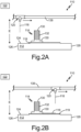
- FIGS. 2A and 2B are simplified illustrations of alternative additive manufacturing system 110, outside the wording of the claims.
- System 110 includes build platform 112, preform 114, metallic powder 118, powder distribution device 120, and energy source 122.
- Build platform 112, metallic powder 118, and energy source 122 can be formed and/or operate in a manner substantially similar to build platform 12, metallic powder 18, and energy source 22 of system 10.
- preform 114 includes generally horizontal surfaces 130, each of which are relatively higher than platform surface 124, and are generally capable of receiving metallic powder 118.
- Preform 114 also includes threaded surface 132.
- Preform 114 can be formed in a manner substantially similar to preforms 14 and 16 of system 10. As can be seen in FIGS. 2A and 2B , preform 114 is secured to build platform 112 via a fused layer of metallic powder 119 disposed along platform surface 124 underneath preform 114. Such an arrangement can be desirable depending on how the preform is incorporated into the design of the hybrid component. In other embodiments, preform 114 can be in contact with only a portion of the fused layer, or it can be secured to build platform 112 in any manner discussed above with respect to preforms 14 and 16.
- Powder distribution device 120 is configured as a biaxial gantry system, and like device 20, is located at an elevation E above build platform 112 and the uppermost surface of preform 114.
- device 120 moves along rail 138 between first end 126 and second end 128 of build platform 112, and deposits metallic powder 118 onto any of surface 124 and surfaces 130. Between each round of deposition, device 120 can further move in a direction orthogonal to its movement along rail 138, in order to deposit metallic powder 118 along the necessary area of build platform 112.
- Device 120 continues to deposit layers of metallic powder 118, and energy source 122 fuses the layers until the hybrid component is complete.
- a hybrid component formed with preform 114 can be, for example, a bracket requiring one or more threaded structures.
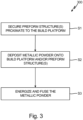
- FIG. 3 illustrates method 300 for fabricating a hybrid component using systems 10 and 110.
- step S1 one or more preforms are secured proximate to the build platform.
- step S2 the powder deposition device deposits metallic powder on the build platform surface and/or the preform surface as it moves from one end of the build platform to another.
- step S3 The deposited powder is energized by the directed energy source to form a fused layer. Steps S2 and S3 are repeated, as necessary, until the desired component is formed.
- Systems 10 and 110 can include additional and/or alternative features beyond those described above. It is further envisioned that many of the features of systems 10 and 110 can be interchangeable.
- systems 10 and 110 can include one or more preforms, and the preforms can be uniform in design or vary. Preforms can include additional shapes and geometries, such as fins, apertures, conical, pyramidal, to name a few, non-limiting examples, and can be variably secured to either or both the platform surface and fused metallic powder, or secured above the platform surface in free space.
- Powder distribution devices 20 and 120 can also be used with either system. Alternative distribution devices, such as a multiaxial robotic arm, are also contemplated.
- Such a device can be used when more precise deposition of metallic powder at various elevations is desired, as well as deposition along non-horizontal surfaces.
- the disclosed systems can alternatively use a fluidized bed powder distribution device to deposit metallic powder onto the build plate and/or preforms.
- Platforms 12 and 112 can be formed as generally planar structures, or can be formed with contours or other surface features to facilitate the securing of the preforms, or to correspond to a desired shape of an additively manufactured portion of the hybrid component.
- Systems 10 and 110 can be used to form any number of hybrid components for use in aerospace, such as turbine engine cooling system components, flow control manifolds, fluid/resin distribution manifolds, heat exchangers, airfoils, and more.
- the disclosed systems and method are further applicable to automotive, maritime, and other transportation industries, as well as industrial and power generation systems.
Landscapes
- Engineering & Computer Science (AREA)
- Chemical & Material Sciences (AREA)
- Manufacturing & Machinery (AREA)
- Materials Engineering (AREA)
- Composite Materials (AREA)
- Mechanical Engineering (AREA)
- Physics & Mathematics (AREA)
- Plasma & Fusion (AREA)
- Powder Metallurgy (AREA)
Claims (10)
- System zum generativen Fertigen (10) zum Herstellen einer hybriden Komponente, wobei das System (10) umfasst:eine Bauplattform (12), umfassend eine Plattformoberfläche (24), die auf einer ersten Höhe lokalisiert ist;eine erste Vorformstruktur (14), die nahe der Bauplattform (12) gesichert ist, wobei die erste Vorformstruktur (14) eine erste Vorformoberfläche (30), die auf einer zweiten Höhe lokalisiert ist, und eine zweite Vorformoberfläche (32) umfasst, wobei die erste Vorformoberfläche (30) eine oberste, äußere Oberfläche der ersten Vorformstruktur (14) ist; undeine Pulverabscheidungsvorrichtung (20), die oberhalb der Bauplattform (12) auf einer dritten Höhe (E) angeordnet ist, wobei die dritte Höhe (E) größer ist als die erste und zweite Höhe,dadurch gekennzeichnet, dass:das System ferner eine zweite Vorformstruktur (16) umfasst, die nahe der Bauplattform (12) gesichert ist, wobei die zweite Vorformstruktur (16) eine äußere Oberfläche (34) und eine nach unten gerichtete Oberfläche (36) umfasst, wobei die äußere Oberfläche (34) eine oberste Oberfläche der zweiten Vorformstruktur (16) ist, die zweite Vorformoberfläche (32) eine innere Oberfläche ist, und die Pulverabscheidungsvorrichtung (20) dazu konfiguriert ist, ein Metallpulver (18) auf die Plattformoberfläche (24), die erste Vorformoberfläche (30) und die äußere Oberfläche (34), aber nicht auf die zweite Vorformoberfläche (32) oder die nach unten gerichtete Oberfläche (36) abzuscheiden; undwobei die Pulverabscheidungsvorrichtung (20) ein einziehbares Förderband (20) umfasst.
- System nach Anspruch 1, wobei die zweite Höhe größer ist als die erste Höhe.
- System nach Anspruch 1 oder 2, ferner umfassend eine gerichtete Energiequelle (22), die dazu konfiguriert ist, das Metallpulver (18) mit Energie zu versorgen und zu schmelzen.
- Verfahren (300) zum Herstellen einer hybriden Komponente, wobei das Verfahren (300) umfasst:Sichern einer ersten Vorformstruktur (14) und einer zweiten Vorformstruktur (16) nahe einer Bauplattform (12), wobei die erste Vorformstruktur (14) eine erste Vorformoberfläche (30) und eine zweite Vorformoberfläche (32) umfasst und die zweite Vorformstruktur (16) eine äußere Oberfläche (34) und eine nach unten gerichtete Oberfläche (36) umfasst, wobei die zweite Vorformoberfläche (32) eine innere Oberfläche ist, die erste Vorformoberfläche (30) eine oberste, äußere Oberfläche der ersten Vorformstruktur (14) ist und die äußere Oberfläche (34) eine oberste Oberfläche der zweiten Vorformstruktur (16) ist;Abscheiden einer ersten Menge eines Metallpulvers (18) auf einer Plattformoberfläche (24), wobei die Plattformoberfläche (24) auf einer ersten Höhe lokalisiert ist;Abscheiden einer zweiten Menge des Metallpulvers (18) auf der ersten Vorformoberfläche (30), wobei die erste Vorformoberfläche (30) auf einer zweiten Höhe lokalisiert ist, und Abscheiden einer dritten Menge des Metallpulvers (18) auf der äußeren Oberfläche (34), aber nicht Abscheiden des Metallpulvers (18) auf der zweiten Vorformoberfläche (32) oder der nach unten gerichteten Oberfläche (36), wobei die erste, zweite und dritte Menge des Metallpulvers (18) unter Verwendung einer Pulverabscheidungsvorrichtung (20) abgeschieden werden, die oberhalb der Bauplattform (12) auf einer dritten Höhe (E) größer als die zweite Höhe angeordnet ist;Versorgen der ersten, zweiten und dritten Menge des Metallpulvers (18) mit Energie, um eine verschmolzene Schicht zu bilden; undWiederholen der Schritte des Abscheidens und des Versorgens mit Energie, um die hybride Komponente zu bilden, wobei die hybride Komponente die erste und zweite Vorformstruktur (14, 16) und eine Vielzahl von verschmolzenen Schichten umfasst.
- Verfahren nach Anspruch 4, wobei die zweite Höhe größer ist als die erste Höhe.
- Verfahren nach Anspruch 4 oder 5, wobei die Pulverabscheidungsvorrichtung (20) ein einziehbares Förderband (20) umfasst.
- Verfahren nach Anspruch 4, 5 oder 6, wobei Sichern der ersten und zweiten Vorformstruktur (14, 16) Löten oder Schweißen der ersten und zweiten Vorformstruktur (14, 16) an einer Oberfläche (24) der Bauplattform (12) umfasst.
- Verfahren nach einem der Ansprüche 4 bis 7, wobei Versorgen des Metallpulvers (18) mit Energie durch eine gerichtete Energiequelle (22) durchgeführt wird, und optional die gerichtete Energiequelle (22) ein Laser oder ein Elektronenstrahl ist.
- Verfahren nach einem der Ansprüche 4 bis 8, wobei das Metallpulver (18) ein Metall oder eine Metalllegierung umfasst, ausgewählt aus der Gruppe, die aus Aluminium, Nickel, Titan, Kobalt, Chrom und Kombinationen davon besteht.
- Verfahren nach einem der Ansprüche 4 bis 9, wobei die erste und/oder zweite Vorformstruktur (14, 16) aus dem gleichen Material wie das Metallpulver (18) gebildet wird.
Applications Claiming Priority (1)
| Application Number | Priority Date | Filing Date | Title |
|---|---|---|---|
| US15/864,771 US20190210113A1 (en) | 2018-01-08 | 2018-01-08 | Hybrid additive manufacturing |
Publications (2)
| Publication Number | Publication Date |
|---|---|
| EP3508288A1 EP3508288A1 (de) | 2019-07-10 |
| EP3508288B1 true EP3508288B1 (de) | 2024-07-17 |
Family
ID=65010612
Family Applications (1)
| Application Number | Title | Priority Date | Filing Date |
|---|---|---|---|
| EP19150769.8A Active EP3508288B1 (de) | 2018-01-08 | 2019-01-08 | Hybride generative fertigung |
Country Status (2)
| Country | Link |
|---|---|
| US (1) | US20190210113A1 (de) |
| EP (1) | EP3508288B1 (de) |
Family Cites Families (11)
| Publication number | Priority date | Publication date | Assignee | Title |
|---|---|---|---|---|
| EP2319641B1 (de) * | 2009-10-30 | 2017-07-19 | Ansaldo Energia IP UK Limited | Verfahren zur Anwendung mehrerer Materialien mit selektivem Laserschmelzen auf einem dreidimensionalen Artikel |
| KR20120063385A (ko) * | 2010-12-07 | 2012-06-15 | 현대자동차주식회사 | 금형 인서트 코어 제조장치 및 방법 |
| US9004866B2 (en) * | 2011-12-06 | 2015-04-14 | Siemens Aktiengesellschaft | Turbine blade incorporating trailing edge cooling design |
| EP3028793A1 (de) * | 2014-12-04 | 2016-06-08 | Siemens Aktiengesellschaft | Verfahren zur Herstellung einer Laufschaufel |
| US10099290B2 (en) * | 2014-12-18 | 2018-10-16 | General Electric Company | Hybrid additive manufacturing methods using hybrid additively manufactured features for hybrid components |
| WO2016152012A1 (ja) * | 2015-03-25 | 2016-09-29 | 株式会社デンソー | 部材の製造方法、多品種部材の製造方法、部材の製造装置、及び、多品種部材の製造システム |
| JP2018523595A (ja) * | 2015-07-17 | 2018-08-23 | アプライド マテリアルズ インコーポレイテッドApplied Materials,Incorporated | 付加製造における複数層の材料の選択的分注及び溶融 |
| US10702921B2 (en) * | 2016-02-05 | 2020-07-07 | Incodema3D, LLC | Additive manufacturing system employing pre-fabricated component bracing |
| EP3442772A4 (de) * | 2016-04-14 | 2019-11-13 | Desktop Metal, Inc. | Generative fertigung mit stützstrukturen |
| US10105902B2 (en) * | 2016-04-18 | 2018-10-23 | Evolve Additive Solutions, Inc. | Electrophotography-based additive manufacturing with part molding |
| US10493532B2 (en) * | 2017-01-17 | 2019-12-03 | General Electric Company | Thermal expansion fit build plate for additive manufacturing |
-
2018
- 2018-01-08 US US15/864,771 patent/US20190210113A1/en not_active Abandoned
-
2019
- 2019-01-08 EP EP19150769.8A patent/EP3508288B1/de active Active
Also Published As
| Publication number | Publication date |
|---|---|
| EP3508288A1 (de) | 2019-07-10 |
| US20190210113A1 (en) | 2019-07-11 |
Similar Documents
| Publication | Publication Date | Title |
|---|---|---|
| Jiménez et al. | Powder-based laser hybrid additive manufacturing of metals: a review | |
| KR20240051135A (ko) | 단일 기계장치에서 비슷하지 않은 작업을 수행하기 위한 시스템 및 방법 | |
| Ding et al. | Wire-feed additive manufacturing of metal components: technologies, developments and future interests | |
| CN109941358B (zh) | 将金属材料加强件施加于金属材料构件的方法 | |
| Duda et al. | 3D metal printing technology | |
| US20200180211A1 (en) | Gear product having reinforced deposition surface and deposition system for manufacturing the same | |
| US8316687B2 (en) | Method for making a tool used to manufacture composite parts | |
| RU2723496C2 (ru) | Способ создания металлических деталей, в котором используется осаждение материала, и устройство для осуществления этого способа | |
| US9562616B2 (en) | Spring assemblies for use in gas turbine engines and methods for their manufacture | |
| CN113084327A (zh) | 用于制造物品的增材搅拌摩擦沉积方法 | |
| KR101860776B1 (ko) | 용접 블랭크 어셈블리 및 방법 | |
| EP3682987A1 (de) | System und verfahren zur herstellung eines objekts | |
| EP3363585A1 (de) | Hergestellter artikel und verfahren | |
| CN107921586B (zh) | 用于制造塑料金属混合构件的方法 | |
| EP1230055A1 (de) | Verfahren zur herstellung von formkörpern oder zum auftragen von beschichtungen | |
| Kapil et al. | 5-axis slicing methods for additive manufacturing process | |
| KR20230095076A (ko) | 저용융점 및 고용융정 초합금의 분말 혼합물의 저온 분사를 사용하여 초합금 부품에 원하는 기하학적 구조를 형성하는 방법 | |
| Sarma et al. | A comparative analysis of trochoidal toolpath with traditional toolpaths used in wire arc-based directed energy deposition process | |
| EP3508288A1 (de) | Hybride generative fertigung | |
| Karunakaran | Hybrid manufacturing | |
| EP0375114A1 (de) | Aufbauen von Werkstücken durch Auftragschweissen | |
| Singh et al. | A nature-inspired build strategy for consistently fabricating intricate objects by wire-arc-based directed energy deposition | |
| CA3188468A1 (en) | Method for producing a layer, manufacturing system and component | |
| Junker et al. | Tailor-made forging tools by Laser Metal Deposition | |
| Kathirvel et al. | A Review on Additive Manufacturing in Industrial Environment |
Legal Events
| Date | Code | Title | Description |
|---|---|---|---|
| PUAI | Public reference made under article 153(3) epc to a published international application that has entered the european phase |
Free format text: ORIGINAL CODE: 0009012 |
|
| STAA | Information on the status of an ep patent application or granted ep patent |
Free format text: STATUS: THE APPLICATION HAS BEEN PUBLISHED |
|
| AK | Designated contracting states |
Kind code of ref document: A1 Designated state(s): AL AT BE BG CH CY CZ DE DK EE ES FI FR GB GR HR HU IE IS IT LI LT LU LV MC MK MT NL NO PL PT RO RS SE SI SK SM TR |
|
| AX | Request for extension of the european patent |
Extension state: BA ME |
|
| STAA | Information on the status of an ep patent application or granted ep patent |
Free format text: STATUS: REQUEST FOR EXAMINATION WAS MADE |
|
| 17P | Request for examination filed |
Effective date: 20200110 |
|
| RBV | Designated contracting states (corrected) |
Designated state(s): AL AT BE BG CH CY CZ DE DK EE ES FI FR GB GR HR HU IE IS IT LI LT LU LV MC MK MT NL NO PL PT RO RS SE SI SK SM TR |
|
| STAA | Information on the status of an ep patent application or granted ep patent |
Free format text: STATUS: EXAMINATION IS IN PROGRESS |
|
| 17Q | First examination report despatched |
Effective date: 20200608 |
|
| RAP1 | Party data changed (applicant data changed or rights of an application transferred) |
Owner name: RAYTHEON TECHNOLOGIES CORPORATION |
|
| REG | Reference to a national code |
Ref country code: DE Ref legal event code: R079 Free format text: PREVIOUS MAIN CLASS: B22F0003105000 Ipc: B22F0010200000 Ref country code: DE Ref legal event code: R079 Ref document number: 602019055239 Country of ref document: DE Free format text: PREVIOUS MAIN CLASS: B22F0003105000 Ipc: B22F0010200000 |
|
| RIC1 | Information provided on ipc code assigned before grant |
Ipc: B22F 10/20 20210101AFI20210527BHEP Ipc: B22F 12/00 20210101ALI20210527BHEP Ipc: B33Y 10/00 20150101ALI20210527BHEP Ipc: B33Y 30/00 20150101ALI20210527BHEP Ipc: B22F 7/08 20060101ALI20210527BHEP |
|
| RAP3 | Party data changed (applicant data changed or rights of an application transferred) |
Owner name: RTX CORPORATION |
|
| REG | Reference to a national code |
Ref country code: DE Ref legal event code: R079 Free format text: PREVIOUS MAIN CLASS: B22F0010200000 Ipc: B33Y0010000000 Ref country code: DE Ref legal event code: R079 Ref document number: 602019055239 Country of ref document: DE Free format text: PREVIOUS MAIN CLASS: B22F0010200000 Ipc: B33Y0010000000 |
|
| GRAP | Despatch of communication of intention to grant a patent |
Free format text: ORIGINAL CODE: EPIDOSNIGR1 |
|
| STAA | Information on the status of an ep patent application or granted ep patent |
Free format text: STATUS: GRANT OF PATENT IS INTENDED |
|
| RIC1 | Information provided on ipc code assigned before grant |
Ipc: B22F 12/50 20210101ALI20240201BHEP Ipc: B22F 10/28 20210101ALI20240201BHEP Ipc: B22F 7/08 20060101ALI20240201BHEP Ipc: B33Y 30/00 20150101ALI20240201BHEP Ipc: B33Y 10/00 20150101AFI20240201BHEP |
|
| INTG | Intention to grant announced |
Effective date: 20240214 |
|
| RIN1 | Information on inventor provided before grant (corrected) |
Inventor name: TWELVES, JR., WENDELL V. Inventor name: THAYER, HENRY H. |
|
| GRAS | Grant fee paid |
Free format text: ORIGINAL CODE: EPIDOSNIGR3 |
|
| GRAA | (expected) grant |
Free format text: ORIGINAL CODE: 0009210 |
|
| STAA | Information on the status of an ep patent application or granted ep patent |
Free format text: STATUS: THE PATENT HAS BEEN GRANTED |
|
| AK | Designated contracting states |
Kind code of ref document: B1 Designated state(s): AL AT BE BG CH CY CZ DE DK EE ES FI FR GB GR HR HU IE IS IT LI LT LU LV MC MK MT NL NO PL PT RO RS SE SI SK SM TR |
|
| REG | Reference to a national code |
Ref country code: CH Ref legal event code: EP |
|
| REG | Reference to a national code |
Ref country code: DE Ref legal event code: R096 Ref document number: 602019055239 Country of ref document: DE |
|
| REG | Reference to a national code |
Ref country code: IE Ref legal event code: FG4D |
|
| REG | Reference to a national code |
Ref country code: LT Ref legal event code: MG9D |
|
| REG | Reference to a national code |
Ref country code: NL Ref legal event code: MP Effective date: 20240717 |
|
| PG25 | Lapsed in a contracting state [announced via postgrant information from national office to epo] |
Ref country code: PT Free format text: LAPSE BECAUSE OF FAILURE TO SUBMIT A TRANSLATION OF THE DESCRIPTION OR TO PAY THE FEE WITHIN THE PRESCRIBED TIME-LIMIT Effective date: 20241118 |
|
| REG | Reference to a national code |
Ref country code: AT Ref legal event code: MK05 Ref document number: 1703765 Country of ref document: AT Kind code of ref document: T Effective date: 20240717 |
|
| PG25 | Lapsed in a contracting state [announced via postgrant information from national office to epo] |
Ref country code: NL Free format text: LAPSE BECAUSE OF FAILURE TO SUBMIT A TRANSLATION OF THE DESCRIPTION OR TO PAY THE FEE WITHIN THE PRESCRIBED TIME-LIMIT Effective date: 20240717 |
|
| PG25 | Lapsed in a contracting state [announced via postgrant information from national office to epo] |
Ref country code: PT Free format text: LAPSE BECAUSE OF FAILURE TO SUBMIT A TRANSLATION OF THE DESCRIPTION OR TO PAY THE FEE WITHIN THE PRESCRIBED TIME-LIMIT Effective date: 20241118 Ref country code: NL Free format text: LAPSE BECAUSE OF FAILURE TO SUBMIT A TRANSLATION OF THE DESCRIPTION OR TO PAY THE FEE WITHIN THE PRESCRIBED TIME-LIMIT Effective date: 20240717 |
|
| PG25 | Lapsed in a contracting state [announced via postgrant information from national office to epo] |
Ref country code: NO Free format text: LAPSE BECAUSE OF FAILURE TO SUBMIT A TRANSLATION OF THE DESCRIPTION OR TO PAY THE FEE WITHIN THE PRESCRIBED TIME-LIMIT Effective date: 20241017 |
|
| PG25 | Lapsed in a contracting state [announced via postgrant information from national office to epo] |
Ref country code: FI Free format text: LAPSE BECAUSE OF FAILURE TO SUBMIT A TRANSLATION OF THE DESCRIPTION OR TO PAY THE FEE WITHIN THE PRESCRIBED TIME-LIMIT Effective date: 20240717 Ref country code: GR Free format text: LAPSE BECAUSE OF FAILURE TO SUBMIT A TRANSLATION OF THE DESCRIPTION OR TO PAY THE FEE WITHIN THE PRESCRIBED TIME-LIMIT Effective date: 20241018 Ref country code: PL Free format text: LAPSE BECAUSE OF FAILURE TO SUBMIT A TRANSLATION OF THE DESCRIPTION OR TO PAY THE FEE WITHIN THE PRESCRIBED TIME-LIMIT Effective date: 20240717 |
|
| PG25 | Lapsed in a contracting state [announced via postgrant information from national office to epo] |
Ref country code: BG Free format text: LAPSE BECAUSE OF FAILURE TO SUBMIT A TRANSLATION OF THE DESCRIPTION OR TO PAY THE FEE WITHIN THE PRESCRIBED TIME-LIMIT Effective date: 20240717 |
|
| PG25 | Lapsed in a contracting state [announced via postgrant information from national office to epo] |
Ref country code: LV Free format text: LAPSE BECAUSE OF FAILURE TO SUBMIT A TRANSLATION OF THE DESCRIPTION OR TO PAY THE FEE WITHIN THE PRESCRIBED TIME-LIMIT Effective date: 20240717 |
|
| PG25 | Lapsed in a contracting state [announced via postgrant information from national office to epo] |
Ref country code: IS Free format text: LAPSE BECAUSE OF FAILURE TO SUBMIT A TRANSLATION OF THE DESCRIPTION OR TO PAY THE FEE WITHIN THE PRESCRIBED TIME-LIMIT Effective date: 20241117 Ref country code: AT Free format text: LAPSE BECAUSE OF FAILURE TO SUBMIT A TRANSLATION OF THE DESCRIPTION OR TO PAY THE FEE WITHIN THE PRESCRIBED TIME-LIMIT Effective date: 20240717 |
|
| PG25 | Lapsed in a contracting state [announced via postgrant information from national office to epo] |
Ref country code: HR Free format text: LAPSE BECAUSE OF FAILURE TO SUBMIT A TRANSLATION OF THE DESCRIPTION OR TO PAY THE FEE WITHIN THE PRESCRIBED TIME-LIMIT Effective date: 20240717 |
|
| PG25 | Lapsed in a contracting state [announced via postgrant information from national office to epo] |
Ref country code: ES Free format text: LAPSE BECAUSE OF FAILURE TO SUBMIT A TRANSLATION OF THE DESCRIPTION OR TO PAY THE FEE WITHIN THE PRESCRIBED TIME-LIMIT Effective date: 20240717 Ref country code: RS Free format text: LAPSE BECAUSE OF FAILURE TO SUBMIT A TRANSLATION OF THE DESCRIPTION OR TO PAY THE FEE WITHIN THE PRESCRIBED TIME-LIMIT Effective date: 20241017 |
|
| PG25 | Lapsed in a contracting state [announced via postgrant information from national office to epo] |
Ref country code: RS Free format text: LAPSE BECAUSE OF FAILURE TO SUBMIT A TRANSLATION OF THE DESCRIPTION OR TO PAY THE FEE WITHIN THE PRESCRIBED TIME-LIMIT Effective date: 20241017 Ref country code: PL Free format text: LAPSE BECAUSE OF FAILURE TO SUBMIT A TRANSLATION OF THE DESCRIPTION OR TO PAY THE FEE WITHIN THE PRESCRIBED TIME-LIMIT Effective date: 20240717 Ref country code: NO Free format text: LAPSE BECAUSE OF FAILURE TO SUBMIT A TRANSLATION OF THE DESCRIPTION OR TO PAY THE FEE WITHIN THE PRESCRIBED TIME-LIMIT Effective date: 20241017 Ref country code: LV Free format text: LAPSE BECAUSE OF FAILURE TO SUBMIT A TRANSLATION OF THE DESCRIPTION OR TO PAY THE FEE WITHIN THE PRESCRIBED TIME-LIMIT Effective date: 20240717 Ref country code: IS Free format text: LAPSE BECAUSE OF FAILURE TO SUBMIT A TRANSLATION OF THE DESCRIPTION OR TO PAY THE FEE WITHIN THE PRESCRIBED TIME-LIMIT Effective date: 20241117 Ref country code: HR Free format text: LAPSE BECAUSE OF FAILURE TO SUBMIT A TRANSLATION OF THE DESCRIPTION OR TO PAY THE FEE WITHIN THE PRESCRIBED TIME-LIMIT Effective date: 20240717 Ref country code: GR Free format text: LAPSE BECAUSE OF FAILURE TO SUBMIT A TRANSLATION OF THE DESCRIPTION OR TO PAY THE FEE WITHIN THE PRESCRIBED TIME-LIMIT Effective date: 20241018 Ref country code: FI Free format text: LAPSE BECAUSE OF FAILURE TO SUBMIT A TRANSLATION OF THE DESCRIPTION OR TO PAY THE FEE WITHIN THE PRESCRIBED TIME-LIMIT Effective date: 20240717 Ref country code: ES Free format text: LAPSE BECAUSE OF FAILURE TO SUBMIT A TRANSLATION OF THE DESCRIPTION OR TO PAY THE FEE WITHIN THE PRESCRIBED TIME-LIMIT Effective date: 20240717 Ref country code: BG Free format text: LAPSE BECAUSE OF FAILURE TO SUBMIT A TRANSLATION OF THE DESCRIPTION OR TO PAY THE FEE WITHIN THE PRESCRIBED TIME-LIMIT Effective date: 20240717 Ref country code: AT Free format text: LAPSE BECAUSE OF FAILURE TO SUBMIT A TRANSLATION OF THE DESCRIPTION OR TO PAY THE FEE WITHIN THE PRESCRIBED TIME-LIMIT Effective date: 20240717 |
|
| PG25 | Lapsed in a contracting state [announced via postgrant information from national office to epo] |
Ref country code: SM Free format text: LAPSE BECAUSE OF FAILURE TO SUBMIT A TRANSLATION OF THE DESCRIPTION OR TO PAY THE FEE WITHIN THE PRESCRIBED TIME-LIMIT Effective date: 20240717 Ref country code: DK Free format text: LAPSE BECAUSE OF FAILURE TO SUBMIT A TRANSLATION OF THE DESCRIPTION OR TO PAY THE FEE WITHIN THE PRESCRIBED TIME-LIMIT Effective date: 20240717 Ref country code: RO Free format text: LAPSE BECAUSE OF FAILURE TO SUBMIT A TRANSLATION OF THE DESCRIPTION OR TO PAY THE FEE WITHIN THE PRESCRIBED TIME-LIMIT Effective date: 20240717 |
|
| REG | Reference to a national code |
Ref country code: DE Ref legal event code: R097 Ref document number: 602019055239 Country of ref document: DE |
|
| PG25 | Lapsed in a contracting state [announced via postgrant information from national office to epo] |
Ref country code: EE Free format text: LAPSE BECAUSE OF FAILURE TO SUBMIT A TRANSLATION OF THE DESCRIPTION OR TO PAY THE FEE WITHIN THE PRESCRIBED TIME-LIMIT Effective date: 20240717 |
|
| PG25 | Lapsed in a contracting state [announced via postgrant information from national office to epo] |
Ref country code: CZ Free format text: LAPSE BECAUSE OF FAILURE TO SUBMIT A TRANSLATION OF THE DESCRIPTION OR TO PAY THE FEE WITHIN THE PRESCRIBED TIME-LIMIT Effective date: 20240717 |
|
| PG25 | Lapsed in a contracting state [announced via postgrant information from national office to epo] |
Ref country code: SK Free format text: LAPSE BECAUSE OF FAILURE TO SUBMIT A TRANSLATION OF THE DESCRIPTION OR TO PAY THE FEE WITHIN THE PRESCRIBED TIME-LIMIT Effective date: 20240717 |
|
| PLBE | No opposition filed within time limit |
Free format text: ORIGINAL CODE: 0009261 |
|
| STAA | Information on the status of an ep patent application or granted ep patent |
Free format text: STATUS: NO OPPOSITION FILED WITHIN TIME LIMIT |
|
| 26N | No opposition filed |
Effective date: 20250422 |
|
| REG | Reference to a national code |
Ref country code: CH Ref legal event code: PL |
|
| PG25 | Lapsed in a contracting state [announced via postgrant information from national office to epo] |
Ref country code: SE Free format text: LAPSE BECAUSE OF FAILURE TO SUBMIT A TRANSLATION OF THE DESCRIPTION OR TO PAY THE FEE WITHIN THE PRESCRIBED TIME-LIMIT Effective date: 20240717 |
|
| PG25 | Lapsed in a contracting state [announced via postgrant information from national office to epo] |
Ref country code: MC Free format text: LAPSE BECAUSE OF FAILURE TO SUBMIT A TRANSLATION OF THE DESCRIPTION OR TO PAY THE FEE WITHIN THE PRESCRIBED TIME-LIMIT Effective date: 20240717 Ref country code: LU Free format text: LAPSE BECAUSE OF NON-PAYMENT OF DUE FEES Effective date: 20250108 |
|
| PG25 | Lapsed in a contracting state [announced via postgrant information from national office to epo] |
Ref country code: BE Free format text: LAPSE BECAUSE OF NON-PAYMENT OF DUE FEES Effective date: 20250131 |
|
| PG25 | Lapsed in a contracting state [announced via postgrant information from national office to epo] |
Ref country code: CH Free format text: LAPSE BECAUSE OF NON-PAYMENT OF DUE FEES Effective date: 20250131 |
|
| REG | Reference to a national code |
Ref country code: BE Ref legal event code: MM Effective date: 20250131 |
|
| PGFP | Annual fee paid to national office [announced via postgrant information from national office to epo] |
Ref country code: GB Payment date: 20251220 Year of fee payment: 8 |
|
| PGFP | Annual fee paid to national office [announced via postgrant information from national office to epo] |
Ref country code: FR Payment date: 20251218 Year of fee payment: 8 |
|
| PG25 | Lapsed in a contracting state [announced via postgrant information from national office to epo] |
Ref country code: IE Free format text: LAPSE BECAUSE OF NON-PAYMENT OF DUE FEES Effective date: 20250108 |
|
| PG25 | Lapsed in a contracting state [announced via postgrant information from national office to epo] |
Ref country code: IT Free format text: LAPSE BECAUSE OF FAILURE TO SUBMIT A TRANSLATION OF THE DESCRIPTION OR TO PAY THE FEE WITHIN THE PRESCRIBED TIME-LIMIT Effective date: 20240717 |
|
| PGFP | Annual fee paid to national office [announced via postgrant information from national office to epo] |
Ref country code: DE Payment date: 20251217 Year of fee payment: 8 |