EP3508238A1 - Support structure - Google Patents
Support structure Download PDFInfo
- Publication number
- EP3508238A1 EP3508238A1 EP18150301.2A EP18150301A EP3508238A1 EP 3508238 A1 EP3508238 A1 EP 3508238A1 EP 18150301 A EP18150301 A EP 18150301A EP 3508238 A1 EP3508238 A1 EP 3508238A1
- Authority
- EP
- European Patent Office
- Prior art keywords
- intermediate structure
- medicament container
- medicament
- flexible
- shaped
- Prior art date
- Legal status (The legal status is an assumption and is not a legal conclusion. Google has not performed a legal analysis and makes no representation as to the accuracy of the status listed.)
- Granted
Links
Images


Classifications
-
- A—HUMAN NECESSITIES
- A61—MEDICAL OR VETERINARY SCIENCE; HYGIENE
- A61M—DEVICES FOR INTRODUCING MEDIA INTO, OR ONTO, THE BODY; DEVICES FOR TRANSDUCING BODY MEDIA OR FOR TAKING MEDIA FROM THE BODY; DEVICES FOR PRODUCING OR ENDING SLEEP OR STUPOR
- A61M5/00—Devices for bringing media into the body in a subcutaneous, intra-vascular or intramuscular way; Accessories therefor, e.g. filling or cleaning devices, arm-rests
- A61M5/178—Syringes
- A61M5/24—Ampoule syringes, i.e. syringes with needle for use in combination with replaceable ampoules or carpules, e.g. automatic
-
- A—HUMAN NECESSITIES
- A61—MEDICAL OR VETERINARY SCIENCE; HYGIENE
- A61M—DEVICES FOR INTRODUCING MEDIA INTO, OR ONTO, THE BODY; DEVICES FOR TRANSDUCING BODY MEDIA OR FOR TAKING MEDIA FROM THE BODY; DEVICES FOR PRODUCING OR ENDING SLEEP OR STUPOR
- A61M5/00—Devices for bringing media into the body in a subcutaneous, intra-vascular or intramuscular way; Accessories therefor, e.g. filling or cleaning devices, arm-rests
- A61M5/002—Packages specially adapted therefor, e.g. for syringes or needles, kits for diabetics
-
- A—HUMAN NECESSITIES
- A61—MEDICAL OR VETERINARY SCIENCE; HYGIENE
- A61M—DEVICES FOR INTRODUCING MEDIA INTO, OR ONTO, THE BODY; DEVICES FOR TRANSDUCING BODY MEDIA OR FOR TAKING MEDIA FROM THE BODY; DEVICES FOR PRODUCING OR ENDING SLEEP OR STUPOR
- A61M5/00—Devices for bringing media into the body in a subcutaneous, intra-vascular or intramuscular way; Accessories therefor, e.g. filling or cleaning devices, arm-rests
- A61M5/178—Syringes
- A61M5/31—Details
- A61M5/3129—Syringe barrels
- A61M5/3135—Syringe barrels characterised by constructional features of the proximal end
-
- A—HUMAN NECESSITIES
- A61—MEDICAL OR VETERINARY SCIENCE; HYGIENE
- A61M—DEVICES FOR INTRODUCING MEDIA INTO, OR ONTO, THE BODY; DEVICES FOR TRANSDUCING BODY MEDIA OR FOR TAKING MEDIA FROM THE BODY; DEVICES FOR PRODUCING OR ENDING SLEEP OR STUPOR
- A61M5/00—Devices for bringing media into the body in a subcutaneous, intra-vascular or intramuscular way; Accessories therefor, e.g. filling or cleaning devices, arm-rests
- A61M5/178—Syringes
- A61M5/20—Automatic syringes, e.g. with automatically actuated piston rod, with automatic needle injection, filling automatically
- A61M2005/2006—Having specific accessories
- A61M2005/2013—Having specific accessories triggering of discharging means by contact of injector with patient body
-
- A—HUMAN NECESSITIES
- A61—MEDICAL OR VETERINARY SCIENCE; HYGIENE
- A61M—DEVICES FOR INTRODUCING MEDIA INTO, OR ONTO, THE BODY; DEVICES FOR TRANSDUCING BODY MEDIA OR FOR TAKING MEDIA FROM THE BODY; DEVICES FOR PRODUCING OR ENDING SLEEP OR STUPOR
- A61M5/00—Devices for bringing media into the body in a subcutaneous, intra-vascular or intramuscular way; Accessories therefor, e.g. filling or cleaning devices, arm-rests
- A61M5/178—Syringes
- A61M5/24—Ampoule syringes, i.e. syringes with needle for use in combination with replaceable ampoules or carpules, e.g. automatic
- A61M2005/2418—Ampoule syringes, i.e. syringes with needle for use in combination with replaceable ampoules or carpules, e.g. automatic comprising means for damping shocks on ampoule
-
- A—HUMAN NECESSITIES
- A61—MEDICAL OR VETERINARY SCIENCE; HYGIENE
- A61M—DEVICES FOR INTRODUCING MEDIA INTO, OR ONTO, THE BODY; DEVICES FOR TRANSDUCING BODY MEDIA OR FOR TAKING MEDIA FROM THE BODY; DEVICES FOR PRODUCING OR ENDING SLEEP OR STUPOR
- A61M5/00—Devices for bringing media into the body in a subcutaneous, intra-vascular or intramuscular way; Accessories therefor, e.g. filling or cleaning devices, arm-rests
- A61M5/178—Syringes
- A61M5/24—Ampoule syringes, i.e. syringes with needle for use in combination with replaceable ampoules or carpules, e.g. automatic
- A61M2005/2433—Ampoule fixed to ampoule holder
- A61M2005/2437—Ampoule fixed to ampoule holder by clamping means
-
- A—HUMAN NECESSITIES
- A61—MEDICAL OR VETERINARY SCIENCE; HYGIENE
- A61M—DEVICES FOR INTRODUCING MEDIA INTO, OR ONTO, THE BODY; DEVICES FOR TRANSDUCING BODY MEDIA OR FOR TAKING MEDIA FROM THE BODY; DEVICES FOR PRODUCING OR ENDING SLEEP OR STUPOR
- A61M5/00—Devices for bringing media into the body in a subcutaneous, intra-vascular or intramuscular way; Accessories therefor, e.g. filling or cleaning devices, arm-rests
- A61M5/178—Syringes
- A61M5/31—Details
- A61M5/32—Needles; Details of needles pertaining to their connection with syringe or hub; Accessories for bringing the needle into, or holding the needle on, the body; Devices for protection of needles
- A61M5/3205—Apparatus for removing or disposing of used needles or syringes, e.g. containers; Means for protection against accidental injuries from used needles
- A61M5/321—Means for protection against accidental injuries by used needles
- A61M5/3243—Means for protection against accidental injuries by used needles being axially-extensible, e.g. protective sleeves coaxially slidable on the syringe barrel
- A61M5/326—Fully automatic sleeve extension, i.e. in which triggering of the sleeve does not require a deliberate action by the user
- A61M2005/3267—Biased sleeves where the needle is uncovered by insertion of the needle into a patient's body
-
- A—HUMAN NECESSITIES
- A61—MEDICAL OR VETERINARY SCIENCE; HYGIENE
- A61M—DEVICES FOR INTRODUCING MEDIA INTO, OR ONTO, THE BODY; DEVICES FOR TRANSDUCING BODY MEDIA OR FOR TAKING MEDIA FROM THE BODY; DEVICES FOR PRODUCING OR ENDING SLEEP OR STUPOR
- A61M2209/00—Ancillary equipment
- A61M2209/08—Supports for equipment
-
- A—HUMAN NECESSITIES
- A61—MEDICAL OR VETERINARY SCIENCE; HYGIENE
- A61M—DEVICES FOR INTRODUCING MEDIA INTO, OR ONTO, THE BODY; DEVICES FOR TRANSDUCING BODY MEDIA OR FOR TAKING MEDIA FROM THE BODY; DEVICES FOR PRODUCING OR ENDING SLEEP OR STUPOR
- A61M5/00—Devices for bringing media into the body in a subcutaneous, intra-vascular or intramuscular way; Accessories therefor, e.g. filling or cleaning devices, arm-rests
- A61M5/178—Syringes
- A61M5/20—Automatic syringes, e.g. with automatically actuated piston rod, with automatic needle injection, filling automatically
- A61M5/2033—Spring-loaded one-shot injectors with or without automatic needle insertion
-
- A—HUMAN NECESSITIES
- A61—MEDICAL OR VETERINARY SCIENCE; HYGIENE
- A61M—DEVICES FOR INTRODUCING MEDIA INTO, OR ONTO, THE BODY; DEVICES FOR TRANSDUCING BODY MEDIA OR FOR TAKING MEDIA FROM THE BODY; DEVICES FOR PRODUCING OR ENDING SLEEP OR STUPOR
- A61M5/00—Devices for bringing media into the body in a subcutaneous, intra-vascular or intramuscular way; Accessories therefor, e.g. filling or cleaning devices, arm-rests
- A61M5/178—Syringes
- A61M5/31—Details
- A61M5/315—Pistons; Piston-rods; Guiding, blocking or restricting the movement of the rod or piston; Appliances on the rod for facilitating dosing ; Dosing mechanisms
- A61M5/31565—Administration mechanisms, i.e. constructional features, modes of administering a dose
- A61M5/31576—Constructional features or modes of drive mechanisms for piston rods
- A61M5/31578—Constructional features or modes of drive mechanisms for piston rods based on axial translation, i.e. components directly operatively associated and axially moved with plunger rod
- A61M5/3158—Constructional features or modes of drive mechanisms for piston rods based on axial translation, i.e. components directly operatively associated and axially moved with plunger rod performed by axially moving actuator operated by user, e.g. an injection button
Definitions
- the present application relates to a support structure for a medicament container for the purpose of holding the medicament container in a steady state inside a medicament delivery device.
- any support for a medicament container should preferably be flexible and possibly also resilient in order to handle forces exerted on the medicament delivery device and thus the medicament container if it e.g. is dropped onto a hard surface.
- the document WO 2011/123024 discloses a medicament delivery device provided with a number of automatic functions, which medicament delivery device has been very well received on the market.
- the medicament delivery device comprises a support structure in the form of arc-shaped flexible elements that are to come in contact with a distal end surface of a medicament container placed in the medicament delivery device.
- the support structure then exerts a force in the proximal direction of the medicament container for preventing movement of the medicament container.
- distal part/end refers to the part/end of the device, or the parts/ends of the members thereof, which during use of the device is located the furthest away from the medicament delivery site of the patient.
- proximal part/end refers to the part/end of the device, or the parts/ends of the members thereof, which during use of the device is located closest to the medicament delivery site of the patient.
- the aim of the present application is to remedy the risks associated with the state of the art technology.
- the aim is solved by the features of the independent patent claims.
- Preferable embodiments form the subject of the dependent patent claims.
- the support structure comprises an intermediate structure for a support structure of a medicament delivery device, where the support structure is arranged to cooperate with a medicament container.
- the support structure comprises a flexible element arranged to exert a force on a distal end surface of the medicament container.
- the intermediate structure is arranged between the flexible element and the end surface and is arranged to guide the flexible element in an outwardly direction in relation to a longitudinal axis when exerting a force on the medicament container.
- the intermediate structure thus ensures that the flexible element of the support structure is guided away from the passage of the medicament container, thus preventing or minimising the risk of a jamming of the flexible element between the medicament container and a plunger rod that is forced to push on a stopper of the medicament container for expelling a dose of medicament.
- the intermediate structure may comprise a ring-shaped element arranged to be placed at a distal passage of the medicament container.
- the ring-shape will have the advantages that it will not add very much to the length of the medicament delivery device since its thickness is reduced.
- the ring-shape will also allow the plunger rod to access the distal end of the medicament container for expelling a dose of medicament.
- the intermediate structure may further comprise a guide element arranged to releasably connect to and guide the flexible element.
- the guide element further provides a safety against the flexible element entering into the distal end of the medicament container.
- the flexible element may comprise at least one arc-shaped structure arranged to a proximal end of a body of the support structure.
- the arc-shaped structure may extend in an inclined direction in relation to the extension of the body.
- the guide element may comprise at least one connection element arranged to engage an outer surface of the arc-shaped structure.
- connection element may comprise a hook, facilitating the connection of the intermediate structure with the flexible elements.
- connection element may comprise distally extending protrusions that are in frictional engagement with the outer surface of the arc-shaped structure. This also facilitates the connection of the intermediate structure with the flexible elements.
- connection elements when two arc-shaped structures are arranged, then two connection elements are arranged, each on an outer side surface of respective arc-shaped structure.
- the connection elements may be resiliently flexible in directions transversal to the longitudinal direction.
- FIG. 1 shows an example of a medicament delivery device in which the intermediate structure according the present application may be utilized.
- the medicament delivery device 10 comprises an elongated housing 12 having a proximal end 14 and a distal end 16 and extending along a longitudinal axis L.
- the interior of the housing is arranged to accommodate a medicament container 18.
- the medicament container 18 shown is provided with an integrated needle 20 and has a movable stopper 22 inside the tubular body thereof.
- the distal end of the medicament container 18 is arranged with a radially extending flange 24.
- the proximal end of the housing 12 is further arranged with a generally tubular medicament delivery member guard 26 that is movable between and extended position, as shown, covering the needle 20 and a retracted position wherein a penetration may be performed with the needle 20.
- the medicament delivery member guard 26 is preferably urged in the proximal direction by a medicament delivery member guard spring 28.
- the distal end of the housing 12 is provided with a power pack 30 comprising an elongated plunger rod 32 that is arranged to act on the stopper 22 for delivering a dose of medicament through the needle 20.
- the plunger rod 32 is driven by a compression spring 34.
- the plunger rod 32 is held with the spring 34 in a tensioned state by radially flexible arms 36 on a generally tubular body 38 of a rear cap 40, which forms a support structure.
- the arms 36 are provided with inwardly directed protrusions 42 that fit into recesses 44 of the plunger rod 32.
- the arms 36 are prevented from releasing the plunger rod 32 by a generally tubular rotator 46 positioned radially outside the arms 36 with inner surfaces of the rotator 46 in contact with outer surfaces of the arms 36.
- the rear cap 40 is attached to the distal end of the housing 12, wherein the distal end of the spring 34 is abutting the rear cap 40.
- the medicament delivery member guard 26 In order to activate the medicament delivery device, the medicament delivery member guard 26 is pushed in the distal direction.
- the distal part of the medicament delivery member guard 26 is arranged with elements that are capable of turning the rotator 46 such that it is no longer in contact with the arms 36.
- the arms 36 are free to move radially outwards and thereby release the plunger rod 32 for a dose delivery sequence.
- the rear cap 40 is further arranged with elements 48 that are flexible in a generally longitudinal direction and that are designed to exert a force on a distal end of the medicament container 18 when the medicament container 18 is inserted into the medicament delivery device.
- the flexible elements 48 comprise two generally arc-shaped structures that are somewhat outwardly inclined in relation to the longitudinal axis of the medicament delivery device.
- an intermediate structure is arranged between the flexible elements 48 and the distal end of the medicament container 18 in order to ensure that the flexible elements 48 cannot enter into the body of the medicament container 18 and possibly get stuck or jammed between the interior of the medicament container 18 and the plunger rod 32.
- Figures 2-6 show a first embodiment of an intermediate structure 50 comprising a ring-shaped element 52 that is intended to abut the distal end surface of the flange 24 of the medicament container 18.
- the ring-shaped element 52 is arranged with a central passage 54 with a diameter somewhat larger than the inner diameter of the medicament container 18.
- the guide elements of the second embodiment comprise two distally directed protrusions or tongues 56.
- the tongues 56 are made integral with the ring-shaped element 52 and are created in a material that permit bending of the tongues pointing in the distal direction. It is however possible that the connection elements are made as rigid protrusions directed in the distal direction.
- the distance D between outer surfaces of the two tongues 56 is chosen such that when the intermediate structure 50 is connected to the flexible elements 48, the flexible elements 48 will flex radially outwards somewhat due to that the outer surfaces of the tongues 56 are in contact with the inwardly directed surfaces of the flexible elements 48, whereby a frictional connection force is obtained, Figs. 4 and 5 .
- the intermediate structure 50 is thus releasably connected to the flexible elements 48.
- the ring-shaped element 52 of the intermediate structure 50 will abut the distal surface of the medicament container 18 whereby the flexible elements 48 will flex radially outwards, Fig. 11 . Due to the connection elements 56, the flexible elements 48 are prevented from entering the distal passage of the medicament container 18. Instead, the connection elements 56 ensure that the flexible elements 48 always are flexing outwards. The flexible elements 48 will lose contact with the connection elements 56 as seen in Fig. 6 , but the intermediate structure 50 will be held in place by the resilient force from the flexible elements 48, pressing the ring-shaped element 52 against the medicament container 18. The central passage 54 of the ring-shaped element 52 will then allow the plunger rod 32 to pass through during a dose delivery sequence of the medicament delivery device.
- a second embodiment of an intermediate structure 60 is shown. It also comprises a ring-shaped element 62 that is intended to abut a distal end surface of the medicament container 18 and in the embodiment shown a surface of the flange 24 of the medicament container 18.
- the ring-shaped element 62 has a central, generally circular, passage 64 that has a diameter that preferably is larger than the inner diameter of the medicament container 18, as will be explained below.
- One side surface of the ring-shaped element 62 is provided with a guide element 66 that in the embodiment shown is in the form of a hook having a gap 68 between the end of the hook 66 and the ring-shaped element 62, forming a connection element. In the embodiment shown the gap 68 is directed inwards.
- the gap may also be directed outwards.
- the dimensions of the hook 66 and the measure of the gap 68 are chosen such that one of the flexible elements 48 may pass the gap 68 and be placed inside the hook 66.
- the cross-sectional shape of the flexible element 48 may be such that the flexible element passes the gap when the intermediate structure 60 is held in one direction and then be turned wherein the flexible element 48 cannot easily pass the gap 68, Fig. 10 .
- the material of the hook 66 may be such that the hook can flex, temporarily widening the gap 68 when the flexible element 48 is pushed through the gap 68.
- the intermediate structure 60 When the intermediate structure 60 is connected to one of the flexible elements 48 I and the ring-shaped element 62 is in contact with the medicament container 18, the other flexible element 48" rests against the ring-shaped element 62 on the opposite side of the hook 66, Fig. 5 .
- the medicament delivery device When now the medicament delivery device is assembled the flexible elements 48 are pressed against the ring-shaped element 62 such that they are flexing radially outwards, Fig. 6 . Since one of the flexible elements 48 I is connected to the hook 66, it is prevented from entering the interior of the medicament container 18. Further because of the connection, the ring-shaped element 62 will move in a radial direction as the connected flexible element 48 I is flexing outwards. The movement of the ring-shaped element 62 will also reduce the risk of the second flexible element 48" from entering the passage of the medicament container as seen in Fig. 11 .
- the intermediate structure of both embodiments may be made in different materials such as metal or plastic, preferably displaying certain resilient properties.
- the first embodiment is preferably made of metal, providing a very thin ring-shaped element with integrated tongues, whereby the distance between the distal end of the medicament container 18 and the proximal end of the body 38 is not limited too much, providing accurate flexing action of the flexible elements 48.
Landscapes
- Health & Medical Sciences (AREA)
- Vascular Medicine (AREA)
- Engineering & Computer Science (AREA)
- Anesthesiology (AREA)
- Biomedical Technology (AREA)
- Heart & Thoracic Surgery (AREA)
- Hematology (AREA)
- Life Sciences & Earth Sciences (AREA)
- Animal Behavior & Ethology (AREA)
- General Health & Medical Sciences (AREA)
- Public Health (AREA)
- Veterinary Medicine (AREA)
- Diabetes (AREA)
- Infusion, Injection, And Reservoir Apparatuses (AREA)
Abstract
Description
- The present application relates to a support structure for a medicament container for the purpose of holding the medicament container in a steady state inside a medicament delivery device.
- Regarding medicament delivery devices having a medicament container assembled therein, it is often a desire that the medicament container is supported such that it may not rattle or move inside the housing of the medicament delivery device. Due to tolerance variations of both the medicament container and the medicament delivery device as such, any support for a medicament container should preferably be flexible and possibly also resilient in order to handle forces exerted on the medicament delivery device and thus the medicament container if it e.g. is dropped onto a hard surface.
- The document
WO 2011/123024 discloses a medicament delivery device provided with a number of automatic functions, which medicament delivery device has been very well received on the market. The medicament delivery device comprises a support structure in the form of arc-shaped flexible elements that are to come in contact with a distal end surface of a medicament container placed in the medicament delivery device. The support structure then exerts a force in the proximal direction of the medicament container for preventing movement of the medicament container. - In most instances this solution works very well. However, there have been instances where the medicament container delivered have had dimensions outside the specification that the medicament delivery device was designed for, and most notably there has been variations in the radius measures of the transition surface between the inner surface of the barrel of the medicament container and the distally directed surface of the flange at the distal end of the medicament container. For batches of medicament containers having large radiuses, there is a risk that the arc-shaped support structures enter into the passage of the medicament container between its inner surface and the plunger rod, thereby risking a jamming of the plunger rod and thereby a malfunction of the medicament delivery device.
- In the present application, when the term "distal part/end" is used, this refers to the part/end of the device, or the parts/ends of the members thereof, which during use of the device is located the furthest away from the medicament delivery site of the patient. Correspondingly, when the term "proximal part/end" is used, this refers to the part/end of the device, or the parts/ends of the members thereof, which during use of the device is located closest to the medicament delivery site of the patient.
- The aim of the present application is to remedy the risks associated with the state of the art technology. The aim is solved by the features of the independent patent claims. Preferable embodiments form the subject of the dependent patent claims.
- According to a main aspect of the application it comprises an intermediate structure for a support structure of a medicament delivery device, where the support structure is arranged to cooperate with a medicament container. The support structure comprises a flexible element arranged to exert a force on a distal end surface of the medicament container. The intermediate structure is arranged between the flexible element and the end surface and is arranged to guide the flexible element in an outwardly direction in relation to a longitudinal axis when exerting a force on the medicament container.
- The intermediate structure thus ensures that the flexible element of the support structure is guided away from the passage of the medicament container, thus preventing or minimising the risk of a jamming of the flexible element between the medicament container and a plunger rod that is forced to push on a stopper of the medicament container for expelling a dose of medicament.
- According to one feasible solution, the intermediate structure may comprise a ring-shaped element arranged to be placed at a distal passage of the medicament container. The ring-shape will have the advantages that it will not add very much to the length of the medicament delivery device since its thickness is reduced. The ring-shape will also allow the plunger rod to access the distal end of the medicament container for expelling a dose of medicament.
- The intermediate structure may further comprise a guide element arranged to releasably connect to and guide the flexible element. The guide element further provides a safety against the flexible element entering into the distal end of the medicament container.
- According to one aspect, the flexible element may comprise at least one arc-shaped structure arranged to a proximal end of a body of the support structure. The arc-shaped structure may extend in an inclined direction in relation to the extension of the body. Further, the guide element may comprise at least one connection element arranged to engage an outer surface of the arc-shaped structure.
- According to one solution the connection element may comprise a hook, facilitating the connection of the intermediate structure with the flexible elements.
- As an alternative, the connection element may comprise distally extending protrusions that are in frictional engagement with the outer surface of the arc-shaped structure. This also facilitates the connection of the intermediate structure with the flexible elements.
- With this solution, when two arc-shaped structures are arranged, then two connection elements are arranged, each on an outer side surface of respective arc-shaped structure. In this regard, the connection elements may be resiliently flexible in directions transversal to the longitudinal direction.
- These and other aspects of, and advantages with, the present invention will become apparent from the following detailed description of the invention and from the accompanying drawings.
- In the following detailed description of the invention, reference will be made to the accompanying drawings, of which
-
Fig. 1 is a cross-sectional view of a medicament delivery device that may utilize the solution according to the present application, -
Fig. 2 is a perspective side view of a first embodiment of an intermediate structure positioned between elements of the medicament delivery device ofFig. 1 , -
Fig. 3 is a perspective view of the intermediate structure ofFig. 2 , -
Fig. 4 is a side view in detail of the intermediate structure ofFig. 2 connected to a flexible element, -
Figs. 5 and 6 are cross-sectional side views of the function of the intermediate structure ofFig. 2 , -
Fig. 7 is a perspective side view of a second embodiment of an intermediate structure positioned between elements of the medicament delivery device ofFig. 1 , -
Fig. 8 is a perspective view of the intermediate structure ofFig. 7 , -
Fig. 9 is a side view in detail of the intermediate structure ofFig. 7 connected to two flexible elements, and -
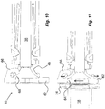
Figs. 10 and 11 are cross-sectional side views of the function of the intermediate structure ofFig. 7 . -
Figure 1 shows an example of a medicament delivery device in which the intermediate structure according the present application may be utilized. Themedicament delivery device 10 comprises anelongated housing 12 having aproximal end 14 and adistal end 16 and extending along a longitudinal axis L. The interior of the housing is arranged to accommodate amedicament container 18. Themedicament container 18 shown is provided with an integratedneedle 20 and has amovable stopper 22 inside the tubular body thereof. The distal end of themedicament container 18 is arranged with a radially extendingflange 24. The proximal end of thehousing 12 is further arranged with a generally tubular medicamentdelivery member guard 26 that is movable between and extended position, as shown, covering theneedle 20 and a retracted position wherein a penetration may be performed with theneedle 20. The medicamentdelivery member guard 26 is preferably urged in the proximal direction by a medicament deliverymember guard spring 28. The distal end of thehousing 12 is provided with apower pack 30 comprising anelongated plunger rod 32 that is arranged to act on thestopper 22 for delivering a dose of medicament through theneedle 20. Theplunger rod 32 is driven by a compression spring 34. - The
plunger rod 32 is held with the spring 34 in a tensioned state by radiallyflexible arms 36 on a generallytubular body 38 of arear cap 40, which forms a support structure. Thearms 36 are provided with inwardly directedprotrusions 42 that fit intorecesses 44 of theplunger rod 32. Thearms 36 are prevented from releasing theplunger rod 32 by a generallytubular rotator 46 positioned radially outside thearms 36 with inner surfaces of therotator 46 in contact with outer surfaces of thearms 36. Therear cap 40 is attached to the distal end of thehousing 12, wherein the distal end of the spring 34 is abutting therear cap 40. - In order to activate the medicament delivery device, the medicament
delivery member guard 26 is pushed in the distal direction. The distal part of the medicamentdelivery member guard 26 is arranged with elements that are capable of turning therotator 46 such that it is no longer in contact with thearms 36. Thus thearms 36 are free to move radially outwards and thereby release theplunger rod 32 for a dose delivery sequence. - The
rear cap 40 is further arranged withelements 48 that are flexible in a generally longitudinal direction and that are designed to exert a force on a distal end of themedicament container 18 when themedicament container 18 is inserted into the medicament delivery device. In the embodiment shown, theflexible elements 48 comprise two generally arc-shaped structures that are somewhat outwardly inclined in relation to the longitudinal axis of the medicament delivery device. - According to the application, an intermediate structure is arranged between the
flexible elements 48 and the distal end of themedicament container 18 in order to ensure that theflexible elements 48 cannot enter into the body of themedicament container 18 and possibly get stuck or jammed between the interior of themedicament container 18 and theplunger rod 32.Figures 2-6 show a first embodiment of anintermediate structure 50 comprising a ring-shapedelement 52 that is intended to abut the distal end surface of theflange 24 of themedicament container 18. The ring-shapedelement 52 is arranged with acentral passage 54 with a diameter somewhat larger than the inner diameter of themedicament container 18. The guide elements of the second embodiment comprise two distally directed protrusions ortongues 56. In the embodiment shown thetongues 56 are made integral with the ring-shapedelement 52 and are created in a material that permit bending of the tongues pointing in the distal direction. It is however possible that the connection elements are made as rigid protrusions directed in the distal direction. The distance D between outer surfaces of the twotongues 56 is chosen such that when theintermediate structure 50 is connected to theflexible elements 48, theflexible elements 48 will flex radially outwards somewhat due to that the outer surfaces of thetongues 56 are in contact with the inwardly directed surfaces of theflexible elements 48, whereby a frictional connection force is obtained,Figs. 4 and5 . Theintermediate structure 50 is thus releasably connected to theflexible elements 48. - When now the
rear cap 40 is to be assembled with themedicament container 18 inside the housing, the ring-shapedelement 52 of theintermediate structure 50 will abut the distal surface of themedicament container 18 whereby theflexible elements 48 will flex radially outwards,Fig. 11 . Due to theconnection elements 56, theflexible elements 48 are prevented from entering the distal passage of themedicament container 18. Instead, theconnection elements 56 ensure that theflexible elements 48 always are flexing outwards. Theflexible elements 48 will lose contact with theconnection elements 56 as seen inFig. 6 , but theintermediate structure 50 will be held in place by the resilient force from theflexible elements 48, pressing the ring-shapedelement 52 against themedicament container 18. Thecentral passage 54 of the ring-shapedelement 52 will then allow theplunger rod 32 to pass through during a dose delivery sequence of the medicament delivery device. - In
figures 7-11 a second embodiment of anintermediate structure 60 is shown. It also comprises a ring-shapedelement 62 that is intended to abut a distal end surface of themedicament container 18 and in the embodiment shown a surface of theflange 24 of themedicament container 18. The ring-shapedelement 62 has a central, generally circular,passage 64 that has a diameter that preferably is larger than the inner diameter of themedicament container 18, as will be explained below. One side surface of the ring-shapedelement 62 is provided with aguide element 66 that in the embodiment shown is in the form of a hook having agap 68 between the end of thehook 66 and the ring-shapedelement 62, forming a connection element. In the embodiment shown thegap 68 is directed inwards. However, it is to be understood that the gap may also be directed outwards. The dimensions of thehook 66 and the measure of thegap 68 are chosen such that one of theflexible elements 48 may pass thegap 68 and be placed inside thehook 66. In this regard the cross-sectional shape of theflexible element 48 may be such that the flexible element passes the gap when theintermediate structure 60 is held in one direction and then be turned wherein theflexible element 48 cannot easily pass thegap 68,Fig. 10 . As an alternative or as an addition the material of thehook 66 may be such that the hook can flex, temporarily widening thegap 68 when theflexible element 48 is pushed through thegap 68. - When the
intermediate structure 60 is connected to one of theflexible elements 48I and the ring-shapedelement 62 is in contact with themedicament container 18, the otherflexible element 48" rests against the ring-shapedelement 62 on the opposite side of thehook 66,Fig. 5 . When now the medicament delivery device is assembled theflexible elements 48 are pressed against the ring-shapedelement 62 such that they are flexing radially outwards,Fig. 6 . Since one of theflexible elements 48I is connected to thehook 66, it is prevented from entering the interior of themedicament container 18. Further because of the connection, the ring-shapedelement 62 will move in a radial direction as the connectedflexible element 48I is flexing outwards. The movement of the ring-shapedelement 62 will also reduce the risk of the secondflexible element 48" from entering the passage of the medicament container as seen inFig. 11 . - The intermediate structure of both embodiments may be made in different materials such as metal or plastic, preferably displaying certain resilient properties. The first embodiment is preferably made of metal, providing a very thin ring-shaped element with integrated tongues, whereby the distance between the distal end of the
medicament container 18 and the proximal end of thebody 38 is not limited too much, providing accurate flexing action of theflexible elements 48. - It is to be understood that the embodiments described above and shown in the drawings are only to be regarded as non-limiting examples and that the present application may be modified in many ways within the scope of the patent claims.
Claims (10)
- Intermediate structure (50; 60) for a support structure (40) of a medicament delivery device, which support structure is to cooperate with a medicament container (18), said support structure (40) comprising a flexible element (48) arranged to exert a force on a distal end surface of said medicament container (18), wherein said intermediate structure (50; 60) is arranged between said flexible element (48) and said end surface and arranged to guide said flexible element (48) in an outwardly direction in relation to a longitudinal axis (L) when exerting a force on said medicament container (18).
- Intermediate structure (50; 60) according to claim 1, comprising a ring-shaped element (52; 62) arranged to be placed at a distal passage of said medicament container (18).
- Intermediate structure (50; 60) according to claim 1 or 2, comprising a guide element (56; 66) arranged to releasably connect to and guide said flexible element (48).
- Intermediate structure (50; 60) according to claim 3, wherein said flexible element (48) comprises at least one arc-shaped structure arranged to a proximal end of a body (38) of said support structure (40) and extending in an inclined direction in relation to the extension of the body (38) and wherein said guide element (56; 66) are arranged to engage an outer surface of said arc-shaped structure (48).
- Intermediate structure (50; 60) according to claim 4, wherein said guide element comprises distally extending elements (56) that are in frictional engagement with the outer surface of the arc-shaped structure (48).
- Intermediate structure (50; 60) according to claim 6, wherein two arc-shaped structures (48) are arranged and wherein two guide elements (56) are arranged, each on an outer side surface of respective arc-shaped structure (48).
- Intermediate structure (50; 60) according to claim 7, wherein said guide elements are resilient tongues (56) flexible in directions transversal to a longitudinal direction (L).
- Intermediate structure (50; 60) according to claim 4, wherein said guide element comprises a hook (66).
- Intermediate structure (50; 60) according to any of the preceding claims, wherein said body (38) is arranged to accommodate a plunger rod (32) and wherein said intermediate structure (50; 60) is arranged with a passage (54; 64) for said plunger rod.
- Medicament delivery device comprising an intermediate structure (50; 60) according to any of the claims 1 to 9.
Priority Applications (2)
| Application Number | Priority Date | Filing Date | Title |
|---|---|---|---|
| EP18150301.2A EP3508238B1 (en) | 2018-01-04 | 2018-01-04 | Support structure |
| US16/221,357 US10857285B2 (en) | 2018-01-04 | 2018-12-14 | Support structure |
Applications Claiming Priority (1)
| Application Number | Priority Date | Filing Date | Title |
|---|---|---|---|
| EP18150301.2A EP3508238B1 (en) | 2018-01-04 | 2018-01-04 | Support structure |
Publications (2)
| Publication Number | Publication Date |
|---|---|
| EP3508238A1 true EP3508238A1 (en) | 2019-07-10 |
| EP3508238B1 EP3508238B1 (en) | 2023-04-12 |
Family
ID=60923399
Family Applications (1)
| Application Number | Title | Priority Date | Filing Date |
|---|---|---|---|
| EP18150301.2A Active EP3508238B1 (en) | 2018-01-04 | 2018-01-04 | Support structure |
Country Status (2)
| Country | Link |
|---|---|
| US (1) | US10857285B2 (en) |
| EP (1) | EP3508238B1 (en) |
Cited By (1)
| Publication number | Priority date | Publication date | Assignee | Title |
|---|---|---|---|---|
| WO2023088687A1 (en) * | 2021-11-17 | 2023-05-25 | Shl Medical Ag | Components and sub-assemblies for medicament delivery devices |
Families Citing this family (2)
| Publication number | Priority date | Publication date | Assignee | Title |
|---|---|---|---|---|
| EP3999149A1 (en) | 2019-07-18 | 2022-05-25 | SHL Medical AG | Support structure, medicament delivery device and method of assemblying |
| US12569621B2 (en) * | 2020-04-07 | 2026-03-10 | Shl Medical Ag | Sub-assembly for medicament delivery device, and medicament delivery device comprising the sub-assembly |
Citations (5)
| Publication number | Priority date | Publication date | Assignee | Title |
|---|---|---|---|---|
| EP0160711A1 (en) * | 1984-05-03 | 1985-11-13 | Bünder Glas GmbH | Injection syringe |
| US20020188251A1 (en) * | 2001-06-08 | 2002-12-12 | Bioject, Inc. | Jet injector apparatus and method |
| JP2004313369A (en) * | 2003-04-15 | 2004-11-11 | Menicon Co Ltd | Cartridge injector, cartridge and ophthalmic injector set equipped with the injector |
| WO2011123024A1 (en) | 2010-03-31 | 2011-10-06 | Shl Group Ab | Medicament delivery device comprising feedback signalling means |
| US20160287790A1 (en) * | 2013-11-01 | 2016-10-06 | Alastair Willoughby | Medicament delivery device sub-assembly |
-
2018
- 2018-01-04 EP EP18150301.2A patent/EP3508238B1/en active Active
- 2018-12-14 US US16/221,357 patent/US10857285B2/en active Active
Patent Citations (5)
| Publication number | Priority date | Publication date | Assignee | Title |
|---|---|---|---|---|
| EP0160711A1 (en) * | 1984-05-03 | 1985-11-13 | Bünder Glas GmbH | Injection syringe |
| US20020188251A1 (en) * | 2001-06-08 | 2002-12-12 | Bioject, Inc. | Jet injector apparatus and method |
| JP2004313369A (en) * | 2003-04-15 | 2004-11-11 | Menicon Co Ltd | Cartridge injector, cartridge and ophthalmic injector set equipped with the injector |
| WO2011123024A1 (en) | 2010-03-31 | 2011-10-06 | Shl Group Ab | Medicament delivery device comprising feedback signalling means |
| US20160287790A1 (en) * | 2013-11-01 | 2016-10-06 | Alastair Willoughby | Medicament delivery device sub-assembly |
Cited By (1)
| Publication number | Priority date | Publication date | Assignee | Title |
|---|---|---|---|---|
| WO2023088687A1 (en) * | 2021-11-17 | 2023-05-25 | Shl Medical Ag | Components and sub-assemblies for medicament delivery devices |
Also Published As
| Publication number | Publication date |
|---|---|
| US20190201612A1 (en) | 2019-07-04 |
| US10857285B2 (en) | 2020-12-08 |
| EP3508238B1 (en) | 2023-04-12 |
Similar Documents
| Publication | Publication Date | Title |
|---|---|---|
| EP3737442B1 (en) | Support structure | |
| US20230347070A1 (en) | Medicament delivery device | |
| KR102399468B1 (en) | Dosing assembly for drug delivery device and drug delivery device comprising same | |
| KR102414648B1 (en) | Dosing assembly for drug delivery device and drug delivery device comprising same | |
| EP3452146B1 (en) | Drive assembly for a medicament delivery device | |
| EP3104914B1 (en) | Rigid needle shield gripping cap assembly | |
| EP3030287B1 (en) | Power unit | |
| EP3285832B1 (en) | Drive mechanism for an autoinjector | |
| EP2451506B1 (en) | Injection device | |
| CN107438442B (en) | Drug delivery device | |
| EP3362127B1 (en) | Injection device | |
| CN107735124B (en) | Injection device | |
| EP3285829B1 (en) | Drive mechanism | |
| EP3908349B1 (en) | Medicament delivery device | |
| JP2010517714A (en) | Disposable syringe having at least one central traction rod | |
| EP3323448A1 (en) | Medicament delivery device | |
| EP2887983B1 (en) | Medicament delivery device | |
| US10857285B2 (en) | Support structure | |
| EP3348294A1 (en) | Medicament delivery device | |
| KR20180015188A (en) | Drug delivery device | |
| KR20190003623A (en) | Operating mechanism | |
| EP3481466B1 (en) | Device for a medicament container |
Legal Events
| Date | Code | Title | Description |
|---|---|---|---|
| PUAI | Public reference made under article 153(3) epc to a published international application that has entered the european phase |
Free format text: ORIGINAL CODE: 0009012 |
|
| STAA | Information on the status of an ep patent application or granted ep patent |
Free format text: STATUS: THE APPLICATION HAS BEEN PUBLISHED |
|
| AK | Designated contracting states |
Kind code of ref document: A1 Designated state(s): AL AT BE BG CH CY CZ DE DK EE ES FI FR GB GR HR HU IE IS IT LI LT LU LV MC MK MT NL NO PL PT RO RS SE SI SK SM TR |
|
| AX | Request for extension of the european patent |
Extension state: BA ME |
|
| STAA | Information on the status of an ep patent application or granted ep patent |
Free format text: STATUS: REQUEST FOR EXAMINATION WAS MADE |
|
| 17P | Request for examination filed |
Effective date: 20190717 |
|
| RBV | Designated contracting states (corrected) |
Designated state(s): AL AT BE BG CH CY CZ DE DK EE ES FI FR GB GR HR HU IE IS IT LI LT LU LV MC MK MT NL NO PL PT RO RS SE SI SK SM TR |
|
| STAA | Information on the status of an ep patent application or granted ep patent |
Free format text: STATUS: EXAMINATION IS IN PROGRESS |
|
| 17Q | First examination report despatched |
Effective date: 20200318 |
|
| GRAP | Despatch of communication of intention to grant a patent |
Free format text: ORIGINAL CODE: EPIDOSNIGR1 |
|
| STAA | Information on the status of an ep patent application or granted ep patent |
Free format text: STATUS: GRANT OF PATENT IS INTENDED |
|
| GRAS | Grant fee paid |
Free format text: ORIGINAL CODE: EPIDOSNIGR3 |
|
| INTG | Intention to grant announced |
Effective date: 20230131 |
|
| GRAA | (expected) grant |
Free format text: ORIGINAL CODE: 0009210 |
|
| STAA | Information on the status of an ep patent application or granted ep patent |
Free format text: STATUS: THE PATENT HAS BEEN GRANTED |
|
| AK | Designated contracting states |
Kind code of ref document: B1 Designated state(s): AL AT BE BG CH CY CZ DE DK EE ES FI FR GB GR HR HU IE IS IT LI LT LU LV MC MK MT NL NO PL PT RO RS SE SI SK SM TR |
|
| REG | Reference to a national code |
Ref country code: GB Ref legal event code: FG4D |
|
| REG | Reference to a national code |
Ref country code: CH Ref legal event code: EP |
|
| REG | Reference to a national code |
Ref country code: DE Ref legal event code: R096 Ref document number: 602018048238 Country of ref document: DE |
|
| REG | Reference to a national code |
Ref country code: IE Ref legal event code: FG4D |
|
| REG | Reference to a national code |
Ref country code: AT Ref legal event code: REF Ref document number: 1559437 Country of ref document: AT Kind code of ref document: T Effective date: 20230515 |
|
| P01 | Opt-out of the competence of the unified patent court (upc) registered |
Effective date: 20230425 |
|
| REG | Reference to a national code |
Ref country code: LT Ref legal event code: MG9D |
|
| REG | Reference to a national code |
Ref country code: NL Ref legal event code: MP Effective date: 20230412 |
|
| REG | Reference to a national code |
Ref country code: AT Ref legal event code: MK05 Ref document number: 1559437 Country of ref document: AT Kind code of ref document: T Effective date: 20230412 |
|
| PG25 | Lapsed in a contracting state [announced via postgrant information from national office to epo] |
Ref country code: NL Free format text: LAPSE BECAUSE OF FAILURE TO SUBMIT A TRANSLATION OF THE DESCRIPTION OR TO PAY THE FEE WITHIN THE PRESCRIBED TIME-LIMIT Effective date: 20230412 |
|
| PG25 | Lapsed in a contracting state [announced via postgrant information from national office to epo] |
Ref country code: SE Free format text: LAPSE BECAUSE OF FAILURE TO SUBMIT A TRANSLATION OF THE DESCRIPTION OR TO PAY THE FEE WITHIN THE PRESCRIBED TIME-LIMIT Effective date: 20230412 Ref country code: PT Free format text: LAPSE BECAUSE OF FAILURE TO SUBMIT A TRANSLATION OF THE DESCRIPTION OR TO PAY THE FEE WITHIN THE PRESCRIBED TIME-LIMIT Effective date: 20230814 Ref country code: NO Free format text: LAPSE BECAUSE OF FAILURE TO SUBMIT A TRANSLATION OF THE DESCRIPTION OR TO PAY THE FEE WITHIN THE PRESCRIBED TIME-LIMIT Effective date: 20230712 Ref country code: ES Free format text: LAPSE BECAUSE OF FAILURE TO SUBMIT A TRANSLATION OF THE DESCRIPTION OR TO PAY THE FEE WITHIN THE PRESCRIBED TIME-LIMIT Effective date: 20230412 Ref country code: AT Free format text: LAPSE BECAUSE OF FAILURE TO SUBMIT A TRANSLATION OF THE DESCRIPTION OR TO PAY THE FEE WITHIN THE PRESCRIBED TIME-LIMIT Effective date: 20230412 |
|
| PG25 | Lapsed in a contracting state [announced via postgrant information from national office to epo] |
Ref country code: RS Free format text: LAPSE BECAUSE OF FAILURE TO SUBMIT A TRANSLATION OF THE DESCRIPTION OR TO PAY THE FEE WITHIN THE PRESCRIBED TIME-LIMIT Effective date: 20230412 Ref country code: PL Free format text: LAPSE BECAUSE OF FAILURE TO SUBMIT A TRANSLATION OF THE DESCRIPTION OR TO PAY THE FEE WITHIN THE PRESCRIBED TIME-LIMIT Effective date: 20230412 Ref country code: LV Free format text: LAPSE BECAUSE OF FAILURE TO SUBMIT A TRANSLATION OF THE DESCRIPTION OR TO PAY THE FEE WITHIN THE PRESCRIBED TIME-LIMIT Effective date: 20230412 Ref country code: LT Free format text: LAPSE BECAUSE OF FAILURE TO SUBMIT A TRANSLATION OF THE DESCRIPTION OR TO PAY THE FEE WITHIN THE PRESCRIBED TIME-LIMIT Effective date: 20230412 Ref country code: IS Free format text: LAPSE BECAUSE OF FAILURE TO SUBMIT A TRANSLATION OF THE DESCRIPTION OR TO PAY THE FEE WITHIN THE PRESCRIBED TIME-LIMIT Effective date: 20230812 Ref country code: HR Free format text: LAPSE BECAUSE OF FAILURE TO SUBMIT A TRANSLATION OF THE DESCRIPTION OR TO PAY THE FEE WITHIN THE PRESCRIBED TIME-LIMIT Effective date: 20230412 Ref country code: GR Free format text: LAPSE BECAUSE OF FAILURE TO SUBMIT A TRANSLATION OF THE DESCRIPTION OR TO PAY THE FEE WITHIN THE PRESCRIBED TIME-LIMIT Effective date: 20230713 Ref country code: AL Free format text: LAPSE BECAUSE OF FAILURE TO SUBMIT A TRANSLATION OF THE DESCRIPTION OR TO PAY THE FEE WITHIN THE PRESCRIBED TIME-LIMIT Effective date: 20230412 |
|
| PG25 | Lapsed in a contracting state [announced via postgrant information from national office to epo] |
Ref country code: FI Free format text: LAPSE BECAUSE OF FAILURE TO SUBMIT A TRANSLATION OF THE DESCRIPTION OR TO PAY THE FEE WITHIN THE PRESCRIBED TIME-LIMIT Effective date: 20230412 |
|
| REG | Reference to a national code |
Ref country code: DE Ref legal event code: R097 Ref document number: 602018048238 Country of ref document: DE |
|
| PG25 | Lapsed in a contracting state [announced via postgrant information from national office to epo] |
Ref country code: SK Free format text: LAPSE BECAUSE OF FAILURE TO SUBMIT A TRANSLATION OF THE DESCRIPTION OR TO PAY THE FEE WITHIN THE PRESCRIBED TIME-LIMIT Effective date: 20230412 |
|
| PG25 | Lapsed in a contracting state [announced via postgrant information from national office to epo] |
Ref country code: SM Free format text: LAPSE BECAUSE OF FAILURE TO SUBMIT A TRANSLATION OF THE DESCRIPTION OR TO PAY THE FEE WITHIN THE PRESCRIBED TIME-LIMIT Effective date: 20230412 Ref country code: SK Free format text: LAPSE BECAUSE OF FAILURE TO SUBMIT A TRANSLATION OF THE DESCRIPTION OR TO PAY THE FEE WITHIN THE PRESCRIBED TIME-LIMIT Effective date: 20230412 Ref country code: RO Free format text: LAPSE BECAUSE OF FAILURE TO SUBMIT A TRANSLATION OF THE DESCRIPTION OR TO PAY THE FEE WITHIN THE PRESCRIBED TIME-LIMIT Effective date: 20230412 Ref country code: EE Free format text: LAPSE BECAUSE OF FAILURE TO SUBMIT A TRANSLATION OF THE DESCRIPTION OR TO PAY THE FEE WITHIN THE PRESCRIBED TIME-LIMIT Effective date: 20230412 Ref country code: DK Free format text: LAPSE BECAUSE OF FAILURE TO SUBMIT A TRANSLATION OF THE DESCRIPTION OR TO PAY THE FEE WITHIN THE PRESCRIBED TIME-LIMIT Effective date: 20230412 Ref country code: CZ Free format text: LAPSE BECAUSE OF FAILURE TO SUBMIT A TRANSLATION OF THE DESCRIPTION OR TO PAY THE FEE WITHIN THE PRESCRIBED TIME-LIMIT Effective date: 20230412 |
|
| PLBE | No opposition filed within time limit |
Free format text: ORIGINAL CODE: 0009261 |
|
| STAA | Information on the status of an ep patent application or granted ep patent |
Free format text: STATUS: NO OPPOSITION FILED WITHIN TIME LIMIT |
|
| 26N | No opposition filed |
Effective date: 20240115 |
|
| PG25 | Lapsed in a contracting state [announced via postgrant information from national office to epo] |
Ref country code: SI Free format text: LAPSE BECAUSE OF FAILURE TO SUBMIT A TRANSLATION OF THE DESCRIPTION OR TO PAY THE FEE WITHIN THE PRESCRIBED TIME-LIMIT Effective date: 20230412 |
|
| PG25 | Lapsed in a contracting state [announced via postgrant information from national office to epo] |
Ref country code: SI Free format text: LAPSE BECAUSE OF FAILURE TO SUBMIT A TRANSLATION OF THE DESCRIPTION OR TO PAY THE FEE WITHIN THE PRESCRIBED TIME-LIMIT Effective date: 20230412 Ref country code: IT Free format text: LAPSE BECAUSE OF FAILURE TO SUBMIT A TRANSLATION OF THE DESCRIPTION OR TO PAY THE FEE WITHIN THE PRESCRIBED TIME-LIMIT Effective date: 20230412 |
|
| PG25 | Lapsed in a contracting state [announced via postgrant information from national office to epo] |
Ref country code: MC Free format text: LAPSE BECAUSE OF FAILURE TO SUBMIT A TRANSLATION OF THE DESCRIPTION OR TO PAY THE FEE WITHIN THE PRESCRIBED TIME-LIMIT Effective date: 20230412 |
|
| PG25 | Lapsed in a contracting state [announced via postgrant information from national office to epo] |
Ref country code: MC Free format text: LAPSE BECAUSE OF FAILURE TO SUBMIT A TRANSLATION OF THE DESCRIPTION OR TO PAY THE FEE WITHIN THE PRESCRIBED TIME-LIMIT Effective date: 20230412 |
|
| PG25 | Lapsed in a contracting state [announced via postgrant information from national office to epo] |
Ref country code: LU Free format text: LAPSE BECAUSE OF NON-PAYMENT OF DUE FEES Effective date: 20240104 |
|
| PG25 | Lapsed in a contracting state [announced via postgrant information from national office to epo] |
Ref country code: LU Free format text: LAPSE BECAUSE OF NON-PAYMENT OF DUE FEES Effective date: 20240104 |
|
| PG25 | Lapsed in a contracting state [announced via postgrant information from national office to epo] |
Ref country code: BE Free format text: LAPSE BECAUSE OF NON-PAYMENT OF DUE FEES Effective date: 20240131 |
|
| PG25 | Lapsed in a contracting state [announced via postgrant information from national office to epo] |
Ref country code: BE Free format text: LAPSE BECAUSE OF NON-PAYMENT OF DUE FEES Effective date: 20240131 |
|
| REG | Reference to a national code |
Ref country code: BE Ref legal event code: MM Effective date: 20240131 |
|
| PG25 | Lapsed in a contracting state [announced via postgrant information from national office to epo] |
Ref country code: BG Free format text: LAPSE BECAUSE OF FAILURE TO SUBMIT A TRANSLATION OF THE DESCRIPTION OR TO PAY THE FEE WITHIN THE PRESCRIBED TIME-LIMIT Effective date: 20230412 |
|
| PG25 | Lapsed in a contracting state [announced via postgrant information from national office to epo] |
Ref country code: BG Free format text: LAPSE BECAUSE OF FAILURE TO SUBMIT A TRANSLATION OF THE DESCRIPTION OR TO PAY THE FEE WITHIN THE PRESCRIBED TIME-LIMIT Effective date: 20230412 |
|
| PG25 | Lapsed in a contracting state [announced via postgrant information from national office to epo] |
Ref country code: IE Free format text: LAPSE BECAUSE OF NON-PAYMENT OF DUE FEES Effective date: 20240104 |
|
| PG25 | Lapsed in a contracting state [announced via postgrant information from national office to epo] |
Ref country code: IE Free format text: LAPSE BECAUSE OF NON-PAYMENT OF DUE FEES Effective date: 20240104 |
|
| PG25 | Lapsed in a contracting state [announced via postgrant information from national office to epo] |
Ref country code: CY Free format text: LAPSE BECAUSE OF FAILURE TO SUBMIT A TRANSLATION OF THE DESCRIPTION OR TO PAY THE FEE WITHIN THE PRESCRIBED TIME-LIMIT; INVALID AB INITIO Effective date: 20180104 |
|
| PG25 | Lapsed in a contracting state [announced via postgrant information from national office to epo] |
Ref country code: HU Free format text: LAPSE BECAUSE OF FAILURE TO SUBMIT A TRANSLATION OF THE DESCRIPTION OR TO PAY THE FEE WITHIN THE PRESCRIBED TIME-LIMIT; INVALID AB INITIO Effective date: 20180104 |
|
| PG25 | Lapsed in a contracting state [announced via postgrant information from national office to epo] |
Ref country code: TR Free format text: LAPSE BECAUSE OF FAILURE TO SUBMIT A TRANSLATION OF THE DESCRIPTION OR TO PAY THE FEE WITHIN THE PRESCRIBED TIME-LIMIT Effective date: 20230412 |
|
| REG | Reference to a national code |
Ref country code: CH Ref legal event code: U11 Free format text: ST27 STATUS EVENT CODE: U-0-0-U10-U11 (AS PROVIDED BY THE NATIONAL OFFICE) Effective date: 20260201 |
|
| PGFP | Annual fee paid to national office [announced via postgrant information from national office to epo] |
Ref country code: GB Payment date: 20260126 Year of fee payment: 9 |
|
| PGFP | Annual fee paid to national office [announced via postgrant information from national office to epo] |
Ref country code: DE Payment date: 20260127 Year of fee payment: 9 |
|
| PGFP | Annual fee paid to national office [announced via postgrant information from national office to epo] |
Ref country code: FR Payment date: 20260126 Year of fee payment: 9 |
|
| PGFP | Annual fee paid to national office [announced via postgrant information from national office to epo] |
Ref country code: CH Payment date: 20260201 Year of fee payment: 9 |