EP3507671B1 - Single thermostat with multiple thermostatic radiator valve controllers - Google Patents
Single thermostat with multiple thermostatic radiator valve controllers Download PDFInfo
- Publication number
- EP3507671B1 EP3507671B1 EP17705221.4A EP17705221A EP3507671B1 EP 3507671 B1 EP3507671 B1 EP 3507671B1 EP 17705221 A EP17705221 A EP 17705221A EP 3507671 B1 EP3507671 B1 EP 3507671B1
- Authority
- EP
- European Patent Office
- Prior art keywords
- trv
- controller
- pin
- valve
- radiator
- Prior art date
- Legal status (The legal status is an assumption and is not a legal conclusion. Google has not performed a legal analysis and makes no representation as to the accuracy of the status listed.)
- Active
Links
Images

Classifications
-
- F—MECHANICAL ENGINEERING; LIGHTING; HEATING; WEAPONS; BLASTING
- F24—HEATING; RANGES; VENTILATING
- F24D—DOMESTIC- OR SPACE-HEATING SYSTEMS, e.g. CENTRAL HEATING SYSTEMS; DOMESTIC HOT-WATER SUPPLY SYSTEMS; ELEMENTS OR COMPONENTS THEREFOR
- F24D19/00—Details
- F24D19/10—Arrangement or mounting of control or safety devices
- F24D19/1006—Arrangement or mounting of control or safety devices for water heating systems
- F24D19/1009—Arrangement or mounting of control or safety devices for water heating systems for central heating
- F24D19/1015—Arrangement or mounting of control or safety devices for water heating systems for central heating using a valve or valves
- F24D19/1018—Radiator valves
-
- F—MECHANICAL ENGINEERING; LIGHTING; HEATING; WEAPONS; BLASTING
- F16—ENGINEERING ELEMENTS AND UNITS; GENERAL MEASURES FOR PRODUCING AND MAINTAINING EFFECTIVE FUNCTIONING OF MACHINES OR INSTALLATIONS; THERMAL INSULATION IN GENERAL
- F16K—VALVES; TAPS; COCKS; ACTUATING-FLOATS; DEVICES FOR VENTING OR AERATING
- F16K31/00—Actuating devices; Operating means; Releasing devices
- F16K31/02—Actuating devices; Operating means; Releasing devices electric; magnetic
- F16K31/04—Actuating devices; Operating means; Releasing devices electric; magnetic using a motor
-
- F—MECHANICAL ENGINEERING; LIGHTING; HEATING; WEAPONS; BLASTING
- F16—ENGINEERING ELEMENTS AND UNITS; GENERAL MEASURES FOR PRODUCING AND MAINTAINING EFFECTIVE FUNCTIONING OF MACHINES OR INSTALLATIONS; THERMAL INSULATION IN GENERAL
- F16K—VALVES; TAPS; COCKS; ACTUATING-FLOATS; DEVICES FOR VENTING OR AERATING
- F16K37/00—Special means in or on valves or other cut-off apparatus for indicating or recording operation thereof, or for enabling an alarm to be given
- F16K37/0075—For recording or indicating the functioning of a valve in combination with test equipment
- F16K37/0083—For recording or indicating the functioning of a valve in combination with test equipment by measuring valve parameters
-
- F—MECHANICAL ENGINEERING; LIGHTING; HEATING; WEAPONS; BLASTING
- F24—HEATING; RANGES; VENTILATING
- F24D—DOMESTIC- OR SPACE-HEATING SYSTEMS, e.g. CENTRAL HEATING SYSTEMS; DOMESTIC HOT-WATER SUPPLY SYSTEMS; ELEMENTS OR COMPONENTS THEREFOR
- F24D19/00—Details
- F24D19/0002—Means for connecting central heating radiators to circulation pipes
- F24D19/0056—Supplies from the central heating system
-
- F—MECHANICAL ENGINEERING; LIGHTING; HEATING; WEAPONS; BLASTING
- F24—HEATING; RANGES; VENTILATING
- F24D—DOMESTIC- OR SPACE-HEATING SYSTEMS, e.g. CENTRAL HEATING SYSTEMS; DOMESTIC HOT-WATER SUPPLY SYSTEMS; ELEMENTS OR COMPONENTS THEREFOR
- F24D19/00—Details
- F24D19/0002—Means for connecting central heating radiators to circulation pipes
- F24D19/0075—Valves for isolating the radiator from the system
-
- G—PHYSICS
- G05—CONTROLLING; REGULATING
- G05D—SYSTEMS FOR CONTROLLING OR REGULATING NON-ELECTRIC VARIABLES
- G05D23/00—Control of temperature
- G05D23/19—Control of temperature characterised by the use of electric means
- G05D23/1902—Control of temperature characterised by the use of electric means characterised by the use of a variable reference value
- G05D23/1905—Control of temperature characterised by the use of electric means characterised by the use of a variable reference value associated with tele control
Definitions
- a thermostatic radiator valve (TRV) controller typically operates in a standalone manner by measuring the surrounding temperature close to the associated radiator and regulates the temperature by adjusting the valve opening.
- the temperature close to the radiator is usually hotter than the actual room temperature.
- the TRV controller can work with a remote thermostat to regulate the room temperature based on the temperature measured with a thermostat mounted on the wall.
- each TRV controller often requires an associated thermostat to operate properly, thus increasing the cost and also complicating the setup of the system.
- EP 2886916 discloses a valve for a heating system comprising a valve closing member movable between a closed position and an open position.
- a control unit is provided which comprises an electronic memory adapted to receive and store an opening limitation value, being a selected intermediate position between the fully open position and the fully closed position of the valve closing member.
- the control unit controls an actuation device controlling the position of the valve closing member.
- a thermostatic radiator valve (TRV) controller comprising: a TRV wireless module; a temperature sensor configured to measure a radiator temperature at a predetermined distance from the radiator; and a TRV controller computing device configured to: perform auto-detection, wherein auto-detection comprises determining a minimum opening position of a pin of a valve of the radiator, and determining a maximum opening position of the pin; receive position information for an operating position of the pin through the TRV wireless module via a wireless channel; and adjust the operating position of the pin between the minimum opening position and the maximum opening position from the position information; characterized in that the step of determining the maximum position of the pin comprises: sensing when the first radiator is transferring a maximum amount of heat; in response to the sensing, registering a first pin position when the maximum amount of heat is transferred; and equating the first maximum opening position to the first pin position.
- auto-detection comprises determining a minimum opening position of a pin of a valve of the radiator, and determining a maximum opening position
- a first thermostatic radiator valve (TRV) controller may be provided with and a single thermostat for use in a heating system for a surrounding room, the thermostat comprising: a thermostat computing device; and a thermostat wireless module; the thermostat computing device configured to perform: sensing a room temperature of the surrounding room; determining a first operating position of a first pin of a first thermostatic valve from the room temperature and a set point temperature of the surrounding room; determining a second operating position of a second pin of a second thermostatic valve from the room temperature and the set point temperature of the surrounding room; and sending first and second position information to the first and second TRV controllers, respectively, through the thermostat wireless module via a wireless channel.
- TRV thermostatic radiator valve
- a heating system may be provided comprising: a first thermostatic radiator valve (TRV) controller according to the first aspect, a second thermostatic radiator valve (TRV) controller according to the first aspect and the single thermostat; a first radiator configured to transfer heat to a surrounding room and comprising a first valve; the first thermostatic radiator valve (TRV) controller configured to control the first valve of the first radiator; and the first valve comprising a first pin, wherein a first operating position of the first pin determines a first amount of heat transferred to the first radiator; the first TRV controller configured to carry out auto-detection in order to automatically determine a first minimum opening position and a first maximum opening position of the first pin; the single thermostat configured to determine the first operating position of the first pin from a room temperature and a set point temperature of the surrounding room and to send first position information indicative of the first operating position to the first TRV controller via a wireless channel; and the first TRV controller configured to adjust the first operating position between the first minimum opening position and the first maximum opening position from the first position information, the heating system further
- the heating system may include a single thermostat that controls multiple thermostatic radiator valve controllers that control heat transfer to radiators in a room.
- the thermostat may include a microcontroller, radio frequency (RF) module or integrated RF circuitry, temperature sensor to sense the room temperature.
- Each thermostatic radiator valve controller may include a microcontroller, RF module or integrated RF circuitry, and temperature sensor to sense the temperature around radiator and is controlled by the thermostat through a wireless channel.
- the thermostat may sense the room temperature and send room temperature, set point temperature, and/or differential of set point temperature and room temperature to thermostatic radiator valve (TRV) controllers.
- TRV thermostatic radiator valve
- the thermostat may sense the room temperature and send a determined valve pin position percentage to the TRV controllers.
- the TRV controller may have the ability to automatically detect the open/closing point of the valve of a radiator by sensing the temperature turning point and register the position as the open/closing point. All further determined pin positions may refer to this open/closing point as the start point of calculation.
- the automatic detection of open/closing point may be performed soon after installation or initiated by an RF command or by an entered command through a keypad in which a sequence of keys represents the entered command entered through a user interface.
- the TRV controller may automatically detect winter operation by checking a signature indicative of a call for heat in order to initiate the auto detection again.
- the TRV controller detects the maximum power output point by checking the rate of temperature rising of the radiator. By acquiring the pin position for maximum heat transfer from the radiator, the TRV controller may register the point as the 100% opening for all subsequent calculations rather than using the fully pin open position.
- FIG. 1 shows a heating system for heating room 100 with multiple thermostatic radiator valve (TRV) controllers 109-111 and single thermostat 112 in accordance with an embodiment of the invention.
- TRV controller 109-111 controls a corresponding valve 106-108, which in turn controls the heat transfer through heat conduit 105 (e.g., heated water pipe from heat source 101) to radiators 102-104, respectively.
- heat conduit 105 e.g., heated water pipe from heat source 101
- Different components may communicate with each other through wireless communication channels via antennas 120-124 or through wired connections.
- Wireless communications may utilize different frequency spectra, including radio frequency (RF), light, and infrared.
- RF radio frequency
- TRV controller 109-111 uses an internal temperature sensor 130-132 to detect the opening point (minimum opening position where the valve begins to open from the closed position) so that all TRV controller 109-111 of room 100 can be operated with the correct opening point when instructed by single thermostat 112. Temperature sensor 130-132 is situated in close proximity of associated radiator 102-104 to properly measure the radiator's temperature. The temperature sensor 130-132 may be housed within the TRV controller 109-111 which is close to the radiator 102-104 or connected via wires to the radiator itself 102-104.
- TRV controller 109-111 also detects the maximum power output point by checking the rate of temperature rising of the radiator as measured through temperature sensors 130-132. By acquiring the maximum power pin position, the TRV controller 109-111 registers the pin position as 100% opening for all subsequent calculations rather than using the fully pin open position.
- Each TRV controller 109-111 adjusts heat transfer to associated radiator 102-104 by controlling the pin position of valve 106-108.
- the amount of the pin movement determines how much the corresponding valve 106-108 is open and consequently the amount of heat transfer from heat conduit 105 to radiator 102-104.
- each TRV controller 109-111 calibrates operation to the actual dimensions of valve 106-108. As will be discussed, TRV controller 109-111 detects the minimum opening position and maximum opening position of the valve pin.
- single thermostat 112 senses room temperature and sends a calculated pin position percentage to TRV controller 109-111, where the percentage is in relation to the open/closed position (0 percentage) to the maximum opening position (100 percentage). Because of characteristic differences among valves 106-108, the associated minimum opening and maximum opening position vary among valves 106-108. However, by providing the calculated pin position percentage by thermostat 112, operation is normalized among TRV controllers 109-111. With an embodiment, the pin percentage sent by the single thermostat 112 does not vary as the TRV controllers 109-111 all receive the same pin percentage.
- Figure 1 shows a system for heating room 100
- some embodiments may be directed to cooling room 100 by cold water rather than hot water being transported by conduit 105.
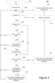
- FIG. 2 shows process 200 for controlling a heating system with single thermostat 112 and at least one thermostatic radiator valve (TRV) controller 109-111 in accordance with an embodiment of the invention.
- process 200 may be performed by each TRV controller 109-111, where processing device 501, as shown in Figure 5 , executes process 200.
- TRV thermostatic radiator valve
- TRV controller 109-111 starts process 212 (e.g., electrical power is applied after installation) at block 201 and initializes at block 202.
- TRV controller 109-111 determines if it is calibrated. For example, as will be discussed, calibration includes the determination of the minimum opening and maximum opening position for associated valve 106-108. If not calibrated, TRV controller executes blocks 204-211 as will be discussed.
- process 200 determines whether the winter flag is set denoting winter mode. While winter mode is typically activated during the winter season, winter mode may be activated during the summer so that TRV controller 109-111 can be calibrated at a desired time. If the winter flag is not set, process 200 continues to block 205. Otherwise, process 200 continues to block 208.
- process 200 determines whether there is a call for heat from the single thermostat 112. If not, process 200 returns to block 203. Otherwise, process 200 continues to block 206.
- TRV controller 109-111 determines whether the temperature has increased by comparing the room temperature as provided by single thermostat 112 from the temperature sensor 403 and the measured temperature from temperature sensor 503 as shown in Figure 5 . If so, process 200 sets the winter flag at block 207 and continues to block 208; otherwise, process 200 returns to block 203.
- process 200 determines whether there is a call for heat. If so, process 200 automatically detects the maximum power point (maximum opening position) at block 211 by associated valve 106-108. With some embodiments, TRV controller 109-111 detects the maximum power output point by checking the rate of temperature rising of the radiator as measured by temperature sensor 503 as shown in Figure 5 . By acquiring the maximum power pin position, TRV controller 109-111 registers the point as the 100 percentage opening for all future calculation rather than using the fully pin open position.
- TRV controller 109-111 determines if the sensor temperature is near room temperature, which is indicative that the pin position is approximately at the opening/closing point of valve 106-108. All further expecting pin position will refer to this open/closing point as the start point of calculation.
- the process 200 automatically detects winter operation by checking a signature indicative of a call for heat in order to initiate the auto detection again. For example, if there is no call for heat for x days, the winter flag is cleared at block 213 and blocks 204-211 are repeated.
- the automatic detection of the open/closing point (minimum pin position) and the maximum power point (maximum opening position) is executed at blocks 210 and 211, respectively, soon after installation, or through a RF command, or through a keypad in which a sequence of keys representing a corresponding command is entered through user interface 505 as shown in Figure 5 .
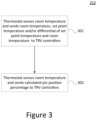
- Figure 3 shows process 212 performed during normal operation in accordance with an embodiment.
- Step 301 may be performed with or without step 302 and step 302 may be performed with or without step 301.
- single thermostat 112 senses the room temperature and sends room temperature, set point temperature and/or differential of set point temperature and room temperature to TRV controllers 109-111. From this data the TRV controllers 109-11 can decide to open or close the valve 106-108.
- single thermostat 112 senses the room temperature and sends a calculated pin position percentage to TRV controller 109, where 0 percentage corresponds to the open/closed position and 100 percentage corresponds to the maximum opening position. From this data the TRV controllers 109-111 can move the valve to the correct position.
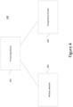
- FIG. 4 shows single thermostat 112 in accordance with an embodiment of the invention.
- Single thermostat 112 comprises processing device 401, wireless module 402 or integrated circuitry, and temperature sensor 403.
- Processing device 401 may assume different forms such as a microcontroller (or MCU, short for microcontroller unit) that may comprise a small computer (SoC) on a single integrated circuit containing a processor core, memory, and programmable input/output peripherals.
- SoC small computer
- Single thermostat 112 may communicate with TRV controllers 109-111 via wireless module 402 via a wireless channel in order to convey information (e.g., a pin position percentage). However, with some embodiments, thermostat 112 and TRV controller 109-111 may communication via a wired configuration.
- the heating system may comprise single thermostat 112 with a microcontroller, radio frequency (RF) module or integrated RF circuitry, and temperature sensor to sense the room temperature.
- RF radio frequency
- Thermostat 112 senses the room temperature utilizing temperature sensor 403 and sends the room temperature, the pin position percentage, set point temperature and/or differential of set point temperature and room temperature to TRV controllers 109-111.
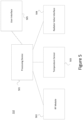
- FIG. 5 shows thermostatic radiator valve (TRV) controller 109 in accordance with an embodiment of the invention.
- TRV controller comprises processing device 501, wireless module 502 or integrated circuitry, temperature sensor 503, radiator valve interface 504, and user interface 505.
- TRV controller 109 may execute in a standalone-mode by measuring the surrounding temperature close to the radiator through temperature sensor 503 and may regulate the temperature by adjusting the valve opening through valve interface 504.
- valve interface 504 comprises a servo motor that moves the valve pin to a desired position and circuitry to control the servo motor.
- the servo motor enables TRV controller 109 to control the linear position of the pin within a desired amount of preciseness.
- temperature sensor 503 is typically close to associated radiator 102-104 (as shown in Figure 1 ), the measured temperature is typically hotter than the actual room temperature when the valve 106 - 108 is open.
- TRV controller 109 can regulate the room temperature based on the temperature measured with thermostat 112 mounted, for example, on a wall or table within the room. The TRV controller 109 now has the room temperature reading from thermostat 112 and can therefore adjust the radiator valve 108 correctly.
- the automatic detection of the open/closing point (minimum pin position) and the maximum power point (maximum opening position) as executed at blocks 210 and 211 shown in Figure 2 , respectively, may be initiated soon after installation, through a command from wireless module 502, or through a keypad in which a sequence of keys are pressed that is indicative of a command via user interface 505. While the keypad may be directly associated with TRV controller 109-111, some embodiments may support a keypad at thermostat 112. In such a case, the entered command may be sent over wireless module 402 to TRV controller 109-111.
- the computing system environment may include a computing device wherein the processes (e.g., shown in Figures 2 and 3 ) discussed herein may be implemented.
- the computing device may have a processor for controlling overall operation of the computing device and its associated components, including RAM, ROM, communications module, and memory device.
- the computing device typically includes a variety of computer readable media.
- Computer readable media may be any available media that may be accessed by computing device and include both volatile and nonvolatile media, removable and non-removable media.
- computer readable media may comprise a combination of computer storage media and communication media.
- Computer storage media may include volatile and nonvolatile, removable and non-removable media implemented in any method or technology for storage of information such as computer readable instructions, data structures, program modules or other data.
- Computer storage media include, but is not limited to, random access memory (RAM), read only memory (ROM), electronically erasable programmable read only memory (EEPROM), flash memory or other memory technology, CD-ROM, digital versatile disks (DVD) or other optical disk storage, magnetic cassettes, magnetic tape, magnetic disk storage or other magnetic storage devices, or any other medium that can be used to store the desired information and that can be accessed by the computing device.
- Communication media typically embodies computer readable instructions, data structures, program modules or other data in a modulated data signal such as a carrier wave or other transport mechanism and includes any information delivery media.
- Modulated data signal is a signal that has one or more of its characteristics set or changed in such a manner as to encode information in the signal.
- communication media includes wired media such as a wired network or direct-wired connection, and wireless media such as acoustic, RF, infrared and other wireless media.
- the computer system may include at least one computer such as a microprocessor, digital signal processor, and associated peripheral electronic circuitry.
Landscapes
- Engineering & Computer Science (AREA)
- General Engineering & Computer Science (AREA)
- Mechanical Engineering (AREA)
- Physics & Mathematics (AREA)
- Thermal Sciences (AREA)
- Chemical & Material Sciences (AREA)
- Combustion & Propulsion (AREA)
- General Physics & Mathematics (AREA)
- Automation & Control Theory (AREA)
- Steam Or Hot-Water Central Heating Systems (AREA)
- Control Of Temperature (AREA)
Description
- This Application claims priority to
U.S. Patent Application No. 15/254042 filed September 1, 2016 - A thermostatic radiator valve (TRV) controller typically operates in a standalone manner by measuring the surrounding temperature close to the associated radiator and regulates the temperature by adjusting the valve opening. However, the temperature close to the radiator is usually hotter than the actual room temperature. With the current RF technology, the TRV controller can work with a remote thermostat to regulate the room temperature based on the temperature measured with a thermostat mounted on the wall.
- However, for larger rooms, there is usually more than one radiator, requiring multiple TRV controllers to control the room. Even with current RF technology, each TRV controller often requires an associated thermostat to operate properly, thus increasing the cost and also complicating the setup of the system.
- Consequently, there is a need for a single thermostat in a room to control multiple TRV controllers in the market. However, with the typical tolerance of the valve's pin length, rubber hardness, and mechanical structure, it is very difficult to adjust the correct opening point for the valve through a TRV controller to have synchronized control of the system when multiple TRV controllers are used in one room.
-
EP 2886916 discloses a valve for a heating system comprising a valve closing member movable between a closed position and an open position. A control unit is provided which comprises an electronic memory adapted to receive and store an opening limitation value, being a selected intermediate position between the fully open position and the fully closed position of the valve closing member. The control unit controls an actuation device controlling the position of the valve closing member. - According to a first aspect of the invention, a thermostatic radiator valve (TRV) controller is provided comprising: a TRV wireless module; a temperature sensor configured to measure a radiator temperature at a predetermined distance from the radiator; and a TRV controller computing device configured to: perform auto-detection, wherein auto-detection comprises determining a minimum opening position of a pin of a valve of the radiator, and determining a maximum opening position of the pin; receive position information for an operating position of the pin through the TRV wireless module via a wireless channel; and adjust the operating position of the pin between the minimum opening position and the maximum opening position from the position information; characterized in that the step of determining the maximum position of the pin comprises: sensing when the first radiator is transferring a maximum amount of heat; in response to the sensing, registering a first pin position when the maximum amount of heat is transferred; and equating the first maximum opening position to the first pin position.
- A first thermostatic radiator valve (TRV) controller according to the first aspect, and a second TRV controller according to the first aspect, may be provided with and a single thermostat for use in a heating system for a surrounding room, the thermostat comprising: a thermostat computing device; and a thermostat wireless module; the thermostat computing device configured to perform: sensing a room temperature of the surrounding room; determining a first operating position of a first pin of a first thermostatic valve from the room temperature and a set point temperature of the surrounding room; determining a second operating position of a second pin of a second thermostatic valve from the room temperature and the set point temperature of the surrounding room; and sending first and second position information to the first and second TRV controllers, respectively, through the thermostat wireless module via a wireless channel.
- A heating system may be provided comprising: a first thermostatic radiator valve (TRV) controller according to the first aspect, a second thermostatic radiator valve (TRV) controller according to the first aspect and the single thermostat; a first radiator configured to transfer heat to a surrounding room and comprising a first valve; the first thermostatic radiator valve (TRV) controller configured to control the first valve of the first radiator; and the first valve comprising a first pin, wherein a first operating position of the first pin determines a first amount of heat transferred to the first radiator; the first TRV controller configured to carry out auto-detection in order to automatically determine a first minimum opening position and a first maximum opening position of the first pin; the single thermostat configured to determine the first operating position of the first pin from a room temperature and a set point temperature of the surrounding room and to send first position information indicative of the first operating position to the first TRV controller via a wireless channel; and the first TRV controller configured to adjust the first operating position between the first minimum opening position and the first maximum opening position from the first position information, the heating system further comprising: a second radiator configured to transfer heat to the surrounding room and comprising a second valve; the second TRV controller configured to control the second valve of the second radiator; the second valve comprising a second pin, wherein a second operating position of the second pin determines a second amount of heat transferred to the second radiator; the second TRV controller configured to automatically determine a second minimum opening position and a second maximum opening position of the second pin; the single thermostat configured to determine the second operating position of the second pin from the room temperature and a set point temperature of the surrounding room and to send second position information indicative of the second operating position to the second TRV controller via a wireless channel; and the second TRV controller configured to adjust the second operating position between the second minimum opening position and the second maximum opening position from the second position information.
- The heating system may include a single thermostat that controls multiple thermostatic radiator valve controllers that control heat transfer to radiators in a room. The thermostat may include a microcontroller, radio frequency (RF) module or integrated RF circuitry, temperature sensor to sense the room temperature. Each thermostatic radiator valve controller may include a microcontroller, RF module or integrated RF circuitry, and temperature sensor to sense the temperature around radiator and is controlled by the thermostat through a wireless channel.
- The thermostat may sense the room temperature and send room temperature, set point temperature, and/or differential of set point temperature and room temperature to thermostatic radiator valve (TRV) controllers.
- The thermostat may sense the room temperature and send a determined valve pin position percentage to the TRV controllers.
- The TRV controller may have the ability to automatically detect the open/closing point of the valve of a radiator by sensing the temperature turning point and register the position as the open/closing point. All further determined pin positions may refer to this open/closing point as the start point of calculation.
- The automatic detection of open/closing point may be performed soon after installation or initiated by an RF command or by an entered command through a keypad in which a sequence of keys represents the entered command entered through a user interface.
- If auto detection fails during summer operation, the TRV controller may automatically detect winter operation by checking a signature indicative of a call for heat in order to initiate the auto detection again.
- The TRV controller detects the maximum power output point by checking the rate of temperature rising of the radiator. By acquiring the pin position for maximum heat transfer from the radiator, the TRV controller may register the point as the 100% opening for all subsequent calculations rather than using the fully pin open position.
- The foregoing summary of the invention, as well as the following detailed description of exemplary embodiments of the invention, is better understood when read in conjunction with the accompanying drawings, which are included by way of example, and not by way of limitation with regard to the claimed invention.
-
Figure 1 shows a heating system for heating a room with multiple thermostatic radiator valve (TRV) controllers and a single thermostat in accordance with an embodiment of the invention. -
Figure 2 shows a flowchart for controlling a heating system with a single thermostat and at least one thermostatic radiator valve (TRV) controller in accordance with an embodiment of the invention. -
Figure 3 shows a flowchart during normal operation in accordance with an embodiment of the invention. -
Figure 4 shows a thermostat in accordance with an embodiment of the invention. -
Figure 5 shows a thermostatic radiator valve (TRV) controller in accordance with an embodiment of the invention. - When heating a larger room, there is usually more than one radiator requiring multiple controllers to control the heating of the room. With traditional systems, each controller often requires an associated thermostat thus increasing the cost and also complicating system setup.
-
Figure 1 shows a heating system forheating room 100 with multiple thermostatic radiator valve (TRV) controllers 109-111 andsingle thermostat 112 in accordance with an embodiment of the invention. Each TRV controller 109-111 controls a corresponding valve 106-108, which in turn controls the heat transfer through heat conduit 105 (e.g., heated water pipe from heat source 101) to radiators 102-104, respectively. - Different components (e.g.,
single thermostat 112, TRV controllers 109-111, and heat source 101) may communicate with each other through wireless communication channels via antennas 120-124 or through wired connections. Wireless communications may utilize different frequency spectra, including radio frequency (RF), light, and infrared. - With traditional heating systems, it is typically difficult to adjust the correct opening point of the valve in order to have synchronized control of the system with multiple valve controllers in one room.
- TRV controller 109-111 uses an internal temperature sensor 130-132 to detect the opening point (minimum opening position where the valve begins to open from the closed position) so that all TRV controller 109-111 of
room 100 can be operated with the correct opening point when instructed bysingle thermostat 112. Temperature sensor 130-132 is situated in close proximity of associated radiator 102-104 to properly measure the radiator's temperature. The temperature sensor 130-132 may be housed within the TRV controller 109-111 which is close to the radiator 102-104 or connected via wires to the radiator itself 102-104. - TRV controller 109-111 also detects the maximum power output point by checking the rate of temperature rising of the radiator as measured through temperature sensors 130-132. By acquiring the maximum power pin position, the TRV controller 109-111 registers the pin position as 100% opening for all subsequent calculations rather than using the fully pin open position.
- Each TRV controller 109-111 adjusts heat transfer to associated radiator 102-104 by controlling the pin position of valve 106-108. The amount of the pin movement determines how much the corresponding valve 106-108 is open and consequently the amount of heat transfer from
heat conduit 105 to radiator 102-104. However, with the tolerance of the valve pin length and rubber hardness and mechanical structure of the valve, each TRV controller 109-111 calibrates operation to the actual dimensions of valve 106-108. As will be discussed, TRV controller 109-111 detects the minimum opening position and maximum opening position of the valve pin. - During normal operation (as will be discussed with
Figure 3 ),single thermostat 112 senses room temperature and sends a calculated pin position percentage to TRV controller 109-111, where the percentage is in relation to the open/closed position (0 percentage) to the maximum opening position (100 percentage). Because of characteristic differences among valves 106-108, the associated minimum opening and maximum opening position vary among valves 106-108. However, by providing the calculated pin position percentage bythermostat 112, operation is normalized among TRV controllers 109-111. With an embodiment, the pin percentage sent by thesingle thermostat 112 does not vary as the TRV controllers 109-111 all receive the same pin percentage. - While
Figure 1 shows a system forheating room 100, some embodiments may be directed tocooling room 100 by cold water rather than hot water being transported byconduit 105. -
Figure 2 showsprocess 200 for controlling a heating system withsingle thermostat 112 and at least one thermostatic radiator valve (TRV) controller 109-111 in accordance with an embodiment of the invention. With some embodiments,process 200 may be performed by each TRV controller 109-111, whereprocessing device 501, as shown inFigure 5 , executesprocess 200. - TRV controller 109-111 starts process 212 (e.g., electrical power is applied after installation) at
block 201 and initializes atblock 202. - At
block 203, TRV controller 109-111 determines if it is calibrated. For example, as will be discussed, calibration includes the determination of the minimum opening and maximum opening position for associated valve 106-108. If not calibrated, TRV controller executes blocks 204-211 as will be discussed. - At
block 204,process 200 determines whether the winter flag is set denoting winter mode. While winter mode is typically activated during the winter season, winter mode may be activated during the summer so that TRV controller 109-111 can be calibrated at a desired time. If the winter flag is not set,process 200 continues to block 205. Otherwise,process 200 continues to block 208. - At
block 205,process 200 determines whether there is a call for heat from thesingle thermostat 112. If not,process 200 returns to block 203. Otherwise,process 200 continues to block 206. - At
block 206, TRV controller 109-111 determines whether the temperature has increased by comparing the room temperature as provided bysingle thermostat 112 from thetemperature sensor 403 and the measured temperature fromtemperature sensor 503 as shown inFigure 5 . If so,process 200 sets the winter flag atblock 207 and continues to block 208; otherwise,process 200 returns to block 203. - At
block 208,process 200 determines whether there is a call for heat. If so,process 200 automatically detects the maximum power point (maximum opening position) atblock 211 by associated valve 106-108. With some embodiments, TRV controller 109-111 detects the maximum power output point by checking the rate of temperature rising of the radiator as measured bytemperature sensor 503 as shown inFigure 5 . By acquiring the maximum power pin position, TRV controller 109-111 registers the point as the 100 percentage opening for all future calculation rather than using the fully pin open position. - At
block 208, ifprocess 200 determines that there is no call for heat, TRV controller 109-111 determines if the sensor temperature is near room temperature, which is indicative that the pin position is approximately at the opening/closing point of valve 106-108. All further expecting pin position will refer to this open/closing point as the start point of calculation. - If during summer operation automatic detection fails, the
process 200 automatically detects winter operation by checking a signature indicative of a call for heat in order to initiate the auto detection again. For example, if there is no call for heat for x days, the winter flag is cleared atblock 213 and blocks 204-211 are repeated. - The automatic detection of the open/closing point (minimum pin position) and the maximum power point (maximum opening position) is executed at
blocks user interface 505 as shown inFigure 5 . -
Figure 3 showsprocess 212 performed during normal operation in accordance with an embodiment. Step 301 may be performed with or withoutstep 302 and step 302 may be performed with or withoutstep 301. - At
block 301,single thermostat 112 senses the room temperature and sends room temperature, set point temperature and/or differential of set point temperature and room temperature to TRV controllers 109-111. From this data the TRV controllers 109-11 can decide to open or close the valve 106-108. - At
block 302,single thermostat 112 senses the room temperature and sends a calculated pin position percentage toTRV controller 109, where 0 percentage corresponds to the open/closed position and 100 percentage corresponds to the maximum opening position. From this data the TRV controllers 109-111 can move the valve to the correct position. -
Figure 4 showssingle thermostat 112 in accordance with an embodiment of the invention.Single thermostat 112 comprisesprocessing device 401,wireless module 402 or integrated circuitry, andtemperature sensor 403.Processing device 401 may assume different forms such as a microcontroller (or MCU, short for microcontroller unit) that may comprise a small computer (SoC) on a single integrated circuit containing a processor core, memory, and programmable input/output peripherals. -
Single thermostat 112 may communicate with TRV controllers 109-111 viawireless module 402 via a wireless channel in order to convey information (e.g., a pin position percentage). However, with some embodiments,thermostat 112 and TRV controller 109-111 may communication via a wired configuration. - The heating system may comprise
single thermostat 112 with a microcontroller, radio frequency (RF) module or integrated RF circuitry, and temperature sensor to sense the room temperature. -
Thermostat 112 senses the room temperature utilizingtemperature sensor 403 and sends the room temperature, the pin position percentage, set point temperature and/or differential of set point temperature and room temperature to TRV controllers 109-111. -
Figure 5 shows thermostatic radiator valve (TRV)controller 109 in accordance with an embodiment of the invention. TRV controller comprisesprocessing device 501,wireless module 502 or integrated circuitry,temperature sensor 503,radiator valve interface 504, anduser interface 505. -
TRV controller 109 may execute in a standalone-mode by measuring the surrounding temperature close to the radiator throughtemperature sensor 503 and may regulate the temperature by adjusting the valve opening throughvalve interface 504. - With some embodiments,
valve interface 504 comprises a servo motor that moves the valve pin to a desired position and circuitry to control the servo motor. The servo motor enablesTRV controller 109 to control the linear position of the pin within a desired amount of preciseness. - Because
temperature sensor 503 is typically close to associated radiator 102-104 (as shown inFigure 1 ), the measured temperature is typically hotter than the actual room temperature when the valve 106 - 108 is open. By communicating withthermostat 112 throughwireless module 502,TRV controller 109 can regulate the room temperature based on the temperature measured withthermostat 112 mounted, for example, on a wall or table within the room. TheTRV controller 109 now has the room temperature reading fromthermostat 112 and can therefore adjust theradiator valve 108 correctly. - The automatic detection of the open/closing point (minimum pin position) and the maximum power point (maximum opening position) as executed at
blocks Figure 2 , respectively, may be initiated soon after installation, through a command fromwireless module 502, or through a keypad in which a sequence of keys are pressed that is indicative of a command viauser interface 505. While the keypad may be directly associated with TRV controller 109-111, some embodiments may support a keypad atthermostat 112. In such a case, the entered command may be sent overwireless module 402 to TRV controller 109-111. - With reference to
Figures 4 and5 , the computing system environment may include a computing device wherein the processes (e.g., shown inFigures 2 and3 ) discussed herein may be implemented. The computing device may have a processor for controlling overall operation of the computing device and its associated components, including RAM, ROM, communications module, and memory device. The computing device typically includes a variety of computer readable media. Computer readable media may be any available media that may be accessed by computing device and include both volatile and nonvolatile media, removable and non-removable media. By way of example, and not limitation, computer readable media may comprise a combination of computer storage media and communication media. - Computer storage media may include volatile and nonvolatile, removable and non-removable media implemented in any method or technology for storage of information such as computer readable instructions, data structures, program modules or other data. Computer storage media include, but is not limited to, random access memory (RAM), read only memory (ROM), electronically erasable programmable read only memory (EEPROM), flash memory or other memory technology, CD-ROM, digital versatile disks (DVD) or other optical disk storage, magnetic cassettes, magnetic tape, magnetic disk storage or other magnetic storage devices, or any other medium that can be used to store the desired information and that can be accessed by the computing device.
- Communication media typically embodies computer readable instructions, data structures, program modules or other data in a modulated data signal such as a carrier wave or other transport mechanism and includes any information delivery media. Modulated data signal is a signal that has one or more of its characteristics set or changed in such a manner as to encode information in the signal. By way of example, and not limitation, communication media includes wired media such as a wired network or direct-wired connection, and wireless media such as acoustic, RF, infrared and other wireless media.
- As can be appreciated by one skilled in the art, a computer system with an associated computer-readable medium containing instructions for controlling the computer system can be utilized to implement the exemplary embodiments that are disclosed herein. The computer system may include at least one computer such as a microprocessor, digital signal processor, and associated peripheral electronic circuitry.
Claims (11)
- A thermostatic radiator valve (TRV) controller (109) comprising:a TRV wireless module (502);a temperature sensor (503) configured to measure a radiator temperature at a predetermined distance from the radiator (102); anda TRV controller computing device configured to:perform auto-detection, wherein auto-detection comprises determining a minimum opening position of a pin of a valve (106) of the radiator, and determining a maximum opening position of the pin;receive position information for an operating position of the pin through the TRV wireless module via a wireless channel; andadjust the operating position of the pin between the minimum opening positionand the maximum opening position from the position information; characterized in that the step of determining the maximum position of the pin comprises:sensing when the first radiator (102) is transferring a maximum amount of heat;in response to the sensing, registering a first pin position when the maximum amount of heat is transferred; andequating the first maximum opening position to the first pin position.
- A thermostatic radiator valve (TRV) controller (109) of claim 1, wherein the determining the minimum position of the pin comprises:sensing a temperature turning point; andin response to the sensing, registering the first minimum opening position of the first pin.
- A first thermostatic radiator valve (TRV) controller (109), a second TRV controller (110), and a single thermostat (112) for use in a heating system for a surrounding room (100), wherein the first and second TRV controllers are TRV controllers according to claim 1 or 2, the thermostat comprising:a thermostat computing device; anda thermostat wireless module (402);the thermostat computing device configured to perform:sensing a room temperature of the surrounding room;determining a first operating position of a first pin of a first thermostatic valve (106) from the room temperature and a set point temperature of the surrounding room;determining a second operating position of a second pin of a second thermostatic valve (107) from the room temperature and the set point temperature of the surrounding room; andsending first and second position information to the first and second TRV controllers (109, 110), respectively, through the thermostat wireless module via a wireless channel.
- The first thermostatic radiator valve (TRV) controller (109), the second thermostatic radiator valve (TRV) controller (110) and the thermostat of claim 3, wherein the thermostat computing device is configured to perform:
sending the room temperature and the set point temperature to the first and second TRV controllers (109, 110). - The first thermostatic radiator valve (TRV) controller (109), the second thermostatic radiator valve (TRV) controller (110) and thermostat of claim 3 or 4, wherein the thermostat computing device is configured to perform:
sending a differential room temperature and a differential set point temperature to the first and second TRV controllers (109, 110). - The first thermostatic radiator valve (TRV) controller (109), the second thermostatic radiator valve (TRV) controller (110) and the thermostat of claim 3, 4 or 5, wherein:the first operating position is indicative of a determined percentage between a first minimum opening position and a first maximum opening position;the second operating position is indicative of the determined percentage between a second minimum opening position and a second maximum opening position;the first minimum opening position and the second minimum opening position are different; andthe first maximum opening position and the second maximum opening position are different.
- A heating system comprising:the first thermostatic radiator valve (TRV) controller (109), the second thermostatic radiator valve (TRV) controller (110) and the single thermostat of any of claims 3 to 6;a first radiator (102) configured to transfer heat to a surrounding room (100) and comprising a first valve (106);the first thermostatic radiator valve (TRV) controller (109) configured to control the first valve of the first radiator; andthe first valve comprising a first pin, wherein a first operating position of the first pin determines a first amount of heat transferred to the first radiator;the first TRV controller configured to carry out auto-detection in order to automatically determine a first minimum opening position and a first maximum opening position of the first pin;the single thermostat configured to determine the first operating position of the first pin from a room temperature and a set point temperature of the surrounding room and to send first position information indicative of the first operating position to the first TRV controller via a wireless channel; andthe first TRV controller configured to adjust the first operating position between the first minimum opening position and the first maximum opening position from the first position information, the heating system further comprising:a second radiator (103) configured to transfer heat to the surrounding room (100) and comprising a second valve (107);the second TRV controller configured to control the second valve of the second radiator;the second valve comprising a second pin, wherein a second operating position of the second pin determines a second amount of heat transferred to the second radiator;the second TRV controller configured to automatically determine a second minimum opening position and a second maximum opening position of the second pin;the single thermostat (112) configured to determine the second operating position of the second pin from the room temperature and a set point temperature of the surrounding room and to send second position information indicative of the second operating position to the second TRV controller via a wireless channel; andthe second TRV controller configured to adjust the second operating position between the second minimum opening position and the second maximum opening position from the second position information.
- The heating system of claim 7, wherein the thermostat comprises:
a temperature sensor (403) configured to measure the room temperature. - The heating system of claim 7 or 8, wherein the first TRV controller comprises:a temperature sensor (503) configured to measure a radiator temperature at a determined distance from the first radiator (102); anda radiator valve interface (504) configured to control a first pin; and/orwherein the first TRV controller (109) is configured to automatically determine the first minimum opening position by:sensing a temperature turning point; andin response to the sensing, registering the first minimum opening position of the first pin; and/orwherein the first TRV controller (109) is configured to automatically determine the first minimum opening position when the TRV controller is installed; and/orwherein the first TRV controller (109) is configured to automatically determine the first minimum opening position when the TRV controller determines when a predetermined command sequence is entered.
- The heating system of any of claims 7, 8 or 9, wherein first and second minimum opening positions are different; and/or
wherein first and second maximum opening positions of the first and second valves, respectively are different. - The heating system of any of claims 7 to 10, wherein:the single thermostat transmits the first position information through the thermostat wireless module; andthe first TRV controller receives the first position information through the first TRV wireless module.
Applications Claiming Priority (2)
| Application Number | Priority Date | Filing Date | Title |
|---|---|---|---|
| US15/254,042 US10578318B2 (en) | 2016-09-01 | 2016-09-01 | Single thermostat with multiple thermostatic radiator valve controllers |
| PCT/US2017/015353 WO2018044344A1 (en) | 2016-09-01 | 2017-01-27 | Single thermostat with multiple thermostatic radiator valve controllers |
Publications (2)
| Publication Number | Publication Date |
|---|---|
| EP3507671A1 EP3507671A1 (en) | 2019-07-10 |
| EP3507671B1 true EP3507671B1 (en) | 2024-09-18 |
Family
ID=58044163
Family Applications (1)
| Application Number | Title | Priority Date | Filing Date |
|---|---|---|---|
| EP17705221.4A Active EP3507671B1 (en) | 2016-09-01 | 2017-01-27 | Single thermostat with multiple thermostatic radiator valve controllers |
Country Status (4)
| Country | Link |
|---|---|
| US (1) | US10578318B2 (en) |
| EP (1) | EP3507671B1 (en) |
| CN (1) | CN109906417B (en) |
| WO (1) | WO2018044344A1 (en) |
Families Citing this family (9)
| Publication number | Priority date | Publication date | Assignee | Title |
|---|---|---|---|---|
| US10697650B2 (en) * | 2016-07-27 | 2020-06-30 | Computime Ltd. | Automatic balance valve control |
| EP3321760B1 (en) | 2016-11-09 | 2021-07-21 | Schneider Electric Controls UK Limited | User interface for a thermostat |
| EP3321596B1 (en) * | 2016-11-09 | 2021-07-28 | Schneider Electric Controls UK Limited | Zoned radiant heating system and method |
| EP3321595B1 (en) | 2016-11-09 | 2020-06-03 | Schneider Electric Controls UK Limited | Zoned radiant heating system and method |
| US10950384B2 (en) | 2017-08-30 | 2021-03-16 | Micron Technology, Inc. | Method used in forming an electronic device comprising conductive material and ferroelectric material |
| US10739017B2 (en) * | 2018-08-20 | 2020-08-11 | Computime Ltd. | Determination of hydronic valve opening point |
| CN110261008B (en) * | 2019-06-11 | 2021-12-14 | 北京无线电计量测试研究所 | Water load calorimeter |
| FR3155049B1 (en) * | 2023-11-02 | 2025-11-07 | Delta Dore | METHOD FOR SETTING A THERMOSTATIC VALVE |
| SK10179Y1 (en) | 2024-02-12 | 2024-11-06 | Amicus Sk, S.R.O. | Heating element valve head, heating control system and method therefor |
Family Cites Families (31)
| Publication number | Priority date | Publication date | Assignee | Title |
|---|---|---|---|---|
| US2210122A (en) * | 1935-05-24 | 1940-08-06 | Honeywell Regulator Co | Control system |
| US3132659A (en) * | 1959-09-01 | 1964-05-12 | North American Aviation Inc | Fluid pressure regulator |
| US4279381A (en) * | 1979-09-28 | 1981-07-21 | Yang Yueh | Method for uniformly heating a multi-level building |
| US4702412A (en) * | 1986-08-15 | 1987-10-27 | Alex Zelczer | Zone control apparatus for central heating and/or cooling systems |
| DK160648B (en) * | 1988-08-05 | 1991-04-02 | Frese Armatur | PROCEDURE FOR REGULATING A CENTRAL OR REMOVAL HEATING SYSTEM WITH A DIFFERENCE PRESSURE VALVE AND PLANT FOR USE THEREOF |
| JPH03251629A (en) * | 1990-03-01 | 1991-11-11 | Matsushita Seiko Co Ltd | Automatic operation device for ventilating fan for bath room |
| CN2064907U (en) * | 1990-03-20 | 1990-10-31 | 吴刚 | Thermostat device |
| US5119988A (en) * | 1990-06-28 | 1992-06-09 | Joachim Fiedrich | Hydronic heating water temperature control system |
| GB2276941A (en) * | 1993-04-08 | 1994-10-12 | Drayton Controls | Controllers for radiator valves |
| DE4319814C1 (en) * | 1993-06-15 | 1995-02-16 | Danfoss As | Radiator thermostatic valve |
| KR100189257B1 (en) * | 1996-06-11 | 1999-06-01 | 정몽규 | Radiator grill adjustable device of vehicle |
| FR2786257B1 (en) * | 1998-11-25 | 2001-01-12 | Comap | HYDRAULIC BALANCING DEVICE FOR A HEATING SYSTEM |
| GB2461857B (en) * | 2008-07-11 | 2012-12-12 | Pegler Ltd | Thermostatic radiator valves and control thereof |
| US20100045470A1 (en) * | 2008-07-31 | 2010-02-25 | Araiza Steven P | Steam distribution control system and method for a steam heating system |
| US8024161B2 (en) * | 2008-08-19 | 2011-09-20 | Honeywell International Inc. | Method and system for model-based multivariable balancing for distributed hydronic networks |
| GB2464095B (en) * | 2008-10-01 | 2012-07-04 | Abdool Raheed Moedeen | Thermostatic heating control system, apparatus and method |
| US8109289B2 (en) * | 2008-12-16 | 2012-02-07 | Honeywell International Inc. | System and method for decentralized balancing of hydronic networks |
| IT1398943B1 (en) * | 2010-03-17 | 2013-03-28 | Ivar Spa | METHOD AND EQUIPMENT TO ADJUST THE TEMPERATURE IN A PLURALITY OF A BUILDING LOCAL |
| SE534920C2 (en) | 2010-06-28 | 2012-02-14 | Tour & Andersson Ab | Valve device for a differential pressure transducer with safety valve |
| US8410944B2 (en) * | 2010-11-18 | 2013-04-02 | Wen-Hui Hung | Radiator detecting device |
| US9423036B1 (en) * | 2011-03-29 | 2016-08-23 | Danfoss A/S | Thermostatic radiator valve insert |
| US8992074B2 (en) * | 2012-02-17 | 2015-03-31 | Cypress Envirosystems, Inc. | System and method for conducting heating, ventilation, and air conditioning analytics |
| CH707402A2 (en) * | 2012-12-18 | 2014-06-30 | Belimo Holding Ag | Method and device for balancing a group of consumers in a fluid transport system. |
| EP3702873A1 (en) * | 2013-12-20 | 2020-09-02 | IMI Hydronic Engineering International SA | A valve and a method of operating a valve |
| CN107110538A (en) * | 2014-10-27 | 2017-08-29 | 胡布控制有限公司 | For temperature controlled system and device |
| US9864383B2 (en) * | 2015-04-02 | 2018-01-09 | Belimo Holding Ag | Method and system for determining characteristic parameters of a hydraulic network |
| US10697650B2 (en) * | 2016-07-27 | 2020-06-30 | Computime Ltd. | Automatic balance valve control |
| EP3339754B1 (en) * | 2016-12-22 | 2020-09-09 | Netatmo | System and method for balancing temperature within a building |
| EP3340003A1 (en) * | 2016-12-22 | 2018-06-27 | Netatmo | Temperature synchronization in a smart thermal management system |
| US10551073B2 (en) * | 2017-03-13 | 2020-02-04 | Schneider Electric Controls Uk Limited | Thermostatic actuator for radiator valve and zoned heating system comprising same |
| DK3404499T3 (en) * | 2017-05-19 | 2021-10-25 | Qsec Ab | PROCEDURE FOR ADJUSTING A CLIMATE SYSTEM |
-
2016
- 2016-09-01 US US15/254,042 patent/US10578318B2/en active Active
-
2017
- 2017-01-27 CN CN201780066166.5A patent/CN109906417B/en active Active
- 2017-01-27 WO PCT/US2017/015353 patent/WO2018044344A1/en not_active Ceased
- 2017-01-27 EP EP17705221.4A patent/EP3507671B1/en active Active
Also Published As
| Publication number | Publication date |
|---|---|
| CN109906417B (en) | 2021-09-14 |
| US20180058705A1 (en) | 2018-03-01 |
| WO2018044344A1 (en) | 2018-03-08 |
| US10578318B2 (en) | 2020-03-03 |
| CN109906417A (en) | 2019-06-18 |
| EP3507671A1 (en) | 2019-07-10 |
Similar Documents
| Publication | Publication Date | Title |
|---|---|---|
| US10578318B2 (en) | Single thermostat with multiple thermostatic radiator valve controllers | |
| RU2660721C2 (en) | Device and method for controlling opening of valve in hvac system | |
| US6522954B1 (en) | Smart control strategy for regulating a temperature controller | |
| EP3561399B1 (en) | Temperature delta control for a hydronic heating/cooling system | |
| CN109764243B (en) | Method for controlling fluid flow through a valve | |
| EP4167376B1 (en) | Heating, ventilation, air conditioning and cooling system comprising antenna extension system and actuator | |
| EP3339754B1 (en) | System and method for balancing temperature within a building | |
| EP3276267B1 (en) | Automatic balance valve assembly, method for controlling water flow and computer-readable medium | |
| EP3115703B1 (en) | Control of heating, ventilation, air conditioning | |
| RU2671139C1 (en) | Indoor temperature control system | |
| EP3997545B1 (en) | Method and system for controlling the temperature of a room | |
| US20230129818A1 (en) | Orientation-based hvac control | |
| EP3039502B1 (en) | Method for temperature control | |
| EP3841332B1 (en) | Determination of hydronic valve opening point | |
| EP3587932B1 (en) | Pulse modulated heating, ventilation, and air conditioning (hvac) control | |
| HK40008561A (en) | Single thermostat with multiple thermostatic radiator valve controllers | |
| HK40008561B (en) | Single thermostat with multiple thermostatic radiator valve controllers | |
| EP3859485B1 (en) | Adaptive boiler control | |
| CN119802717B (en) | Methods and apparatus for controlling underfloor heating, underfloor heating systems, and storage media. | |
| US11959657B2 (en) | Methods and apparatuses for controlling HVAC for user comfort using heat signals | |
| HK40020324A (en) | Pulse modulated heating, ventilation, and air conditioning (hvac) control | |
| KR20240106797A (en) | Apparatus and methods for correcting frequency |
Legal Events
| Date | Code | Title | Description |
|---|---|---|---|
| STAA | Information on the status of an ep patent application or granted ep patent |
Free format text: STATUS: UNKNOWN |
|
| STAA | Information on the status of an ep patent application or granted ep patent |
Free format text: STATUS: THE INTERNATIONAL PUBLICATION HAS BEEN MADE |
|
| PUAI | Public reference made under article 153(3) epc to a published international application that has entered the european phase |
Free format text: ORIGINAL CODE: 0009012 |
|
| STAA | Information on the status of an ep patent application or granted ep patent |
Free format text: STATUS: REQUEST FOR EXAMINATION WAS MADE |
|
| 17P | Request for examination filed |
Effective date: 20190401 |
|
| AK | Designated contracting states |
Kind code of ref document: A1 Designated state(s): AL AT BE BG CH CY CZ DE DK EE ES FI FR GB GR HR HU IE IS IT LI LT LU LV MC MK MT NL NO PL PT RO RS SE SI SK SM TR |
|
| AX | Request for extension of the european patent |
Extension state: BA ME |
|
| DAV | Request for validation of the european patent (deleted) | ||
| DAX | Request for extension of the european patent (deleted) | ||
| STAA | Information on the status of an ep patent application or granted ep patent |
Free format text: STATUS: EXAMINATION IS IN PROGRESS |
|
| 17Q | First examination report despatched |
Effective date: 20200403 |
|
| RAP3 | Party data changed (applicant data changed or rights of an application transferred) |
Owner name: COMPUTIME LTD. |
|
| RIN1 | Information on inventor provided before grant (corrected) |
Inventor name: HA, WAI-LEUNG Inventor name: SMITH, PHILIP JOHN Inventor name: LIAO, HONG BIN |
|
| REG | Reference to a national code |
Ref country code: DE Ref legal event code: R079 Free format text: PREVIOUS MAIN CLASS: G05D0023000000 Ipc: F24D0019000000 Ref country code: DE Ref legal event code: R079 Ref document number: 602017084903 Country of ref document: DE Free format text: PREVIOUS MAIN CLASS: G05D0023000000 Ipc: F24D0019000000 |
|
| RIC1 | Information provided on ipc code assigned before grant |
Ipc: F16K 37/00 20060101ALI20230530BHEP Ipc: F16K 31/04 20060101ALI20230530BHEP Ipc: G05D 23/19 20060101ALI20230530BHEP Ipc: F24D 19/10 20060101ALI20230530BHEP Ipc: F24D 19/00 20060101AFI20230530BHEP |
|
| GRAP | Despatch of communication of intention to grant a patent |
Free format text: ORIGINAL CODE: EPIDOSNIGR1 |
|
| STAA | Information on the status of an ep patent application or granted ep patent |
Free format text: STATUS: GRANT OF PATENT IS INTENDED |
|
| INTG | Intention to grant announced |
Effective date: 20240415 |
|
| GRAS | Grant fee paid |
Free format text: ORIGINAL CODE: EPIDOSNIGR3 |
|
| GRAA | (expected) grant |
Free format text: ORIGINAL CODE: 0009210 |
|
| STAA | Information on the status of an ep patent application or granted ep patent |
Free format text: STATUS: THE PATENT HAS BEEN GRANTED |
|
| AK | Designated contracting states |
Kind code of ref document: B1 Designated state(s): AL AT BE BG CH CY CZ DE DK EE ES FI FR GB GR HR HU IE IS IT LI LT LU LV MC MK MT NL NO PL PT RO RS SE SI SK SM TR |
|
| REG | Reference to a national code |
Ref country code: GB Ref legal event code: FG4D |
|
| REG | Reference to a national code |
Ref country code: CH Ref legal event code: EP |
|
| REG | Reference to a national code |
Ref country code: IE Ref legal event code: FG4D |
|
| REG | Reference to a national code |
Ref country code: DE Ref legal event code: R096 Ref document number: 602017084903 Country of ref document: DE |
|
| REG | Reference to a national code |
Ref country code: LT Ref legal event code: MG9D |
|
| PG25 | Lapsed in a contracting state [announced via postgrant information from national office to epo] |
Ref country code: NO Free format text: LAPSE BECAUSE OF FAILURE TO SUBMIT A TRANSLATION OF THE DESCRIPTION OR TO PAY THE FEE WITHIN THE PRESCRIBED TIME-LIMIT Effective date: 20241218 |
|
| PG25 | Lapsed in a contracting state [announced via postgrant information from national office to epo] |
Ref country code: GR Free format text: LAPSE BECAUSE OF FAILURE TO SUBMIT A TRANSLATION OF THE DESCRIPTION OR TO PAY THE FEE WITHIN THE PRESCRIBED TIME-LIMIT Effective date: 20241219 Ref country code: FI Free format text: LAPSE BECAUSE OF FAILURE TO SUBMIT A TRANSLATION OF THE DESCRIPTION OR TO PAY THE FEE WITHIN THE PRESCRIBED TIME-LIMIT Effective date: 20240918 |
|
| PG25 | Lapsed in a contracting state [announced via postgrant information from national office to epo] |
Ref country code: BG Free format text: LAPSE BECAUSE OF FAILURE TO SUBMIT A TRANSLATION OF THE DESCRIPTION OR TO PAY THE FEE WITHIN THE PRESCRIBED TIME-LIMIT Effective date: 20240918 |
|
| PG25 | Lapsed in a contracting state [announced via postgrant information from national office to epo] |
Ref country code: LV Free format text: LAPSE BECAUSE OF FAILURE TO SUBMIT A TRANSLATION OF THE DESCRIPTION OR TO PAY THE FEE WITHIN THE PRESCRIBED TIME-LIMIT Effective date: 20240918 |
|
| PG25 | Lapsed in a contracting state [announced via postgrant information from national office to epo] |
Ref country code: HR Free format text: LAPSE BECAUSE OF FAILURE TO SUBMIT A TRANSLATION OF THE DESCRIPTION OR TO PAY THE FEE WITHIN THE PRESCRIBED TIME-LIMIT Effective date: 20240918 |
|
| REG | Reference to a national code |
Ref country code: NL Ref legal event code: MP Effective date: 20240918 |
|
| PG25 | Lapsed in a contracting state [announced via postgrant information from national office to epo] |
Ref country code: RS Free format text: LAPSE BECAUSE OF FAILURE TO SUBMIT A TRANSLATION OF THE DESCRIPTION OR TO PAY THE FEE WITHIN THE PRESCRIBED TIME-LIMIT Effective date: 20241218 |
|
| PG25 | Lapsed in a contracting state [announced via postgrant information from national office to epo] |
Ref country code: RS Free format text: LAPSE BECAUSE OF FAILURE TO SUBMIT A TRANSLATION OF THE DESCRIPTION OR TO PAY THE FEE WITHIN THE PRESCRIBED TIME-LIMIT Effective date: 20241218 Ref country code: NO Free format text: LAPSE BECAUSE OF FAILURE TO SUBMIT A TRANSLATION OF THE DESCRIPTION OR TO PAY THE FEE WITHIN THE PRESCRIBED TIME-LIMIT Effective date: 20241218 Ref country code: LV Free format text: LAPSE BECAUSE OF FAILURE TO SUBMIT A TRANSLATION OF THE DESCRIPTION OR TO PAY THE FEE WITHIN THE PRESCRIBED TIME-LIMIT Effective date: 20240918 Ref country code: HR Free format text: LAPSE BECAUSE OF FAILURE TO SUBMIT A TRANSLATION OF THE DESCRIPTION OR TO PAY THE FEE WITHIN THE PRESCRIBED TIME-LIMIT Effective date: 20240918 Ref country code: GR Free format text: LAPSE BECAUSE OF FAILURE TO SUBMIT A TRANSLATION OF THE DESCRIPTION OR TO PAY THE FEE WITHIN THE PRESCRIBED TIME-LIMIT Effective date: 20241219 Ref country code: FI Free format text: LAPSE BECAUSE OF FAILURE TO SUBMIT A TRANSLATION OF THE DESCRIPTION OR TO PAY THE FEE WITHIN THE PRESCRIBED TIME-LIMIT Effective date: 20240918 Ref country code: BG Free format text: LAPSE BECAUSE OF FAILURE TO SUBMIT A TRANSLATION OF THE DESCRIPTION OR TO PAY THE FEE WITHIN THE PRESCRIBED TIME-LIMIT Effective date: 20240918 |
|
| REG | Reference to a national code |
Ref country code: AT Ref legal event code: MK05 Ref document number: 1724987 Country of ref document: AT Kind code of ref document: T Effective date: 20240918 |
|
| PG25 | Lapsed in a contracting state [announced via postgrant information from national office to epo] |
Ref country code: NL Free format text: LAPSE BECAUSE OF FAILURE TO SUBMIT A TRANSLATION OF THE DESCRIPTION OR TO PAY THE FEE WITHIN THE PRESCRIBED TIME-LIMIT Effective date: 20240918 |
|
| PG25 | Lapsed in a contracting state [announced via postgrant information from national office to epo] |
Ref country code: PT Free format text: LAPSE BECAUSE OF FAILURE TO SUBMIT A TRANSLATION OF THE DESCRIPTION OR TO PAY THE FEE WITHIN THE PRESCRIBED TIME-LIMIT Effective date: 20250120 Ref country code: IS Free format text: LAPSE BECAUSE OF FAILURE TO SUBMIT A TRANSLATION OF THE DESCRIPTION OR TO PAY THE FEE WITHIN THE PRESCRIBED TIME-LIMIT Effective date: 20250118 |
|
| PG25 | Lapsed in a contracting state [announced via postgrant information from national office to epo] |
Ref country code: SM Free format text: LAPSE BECAUSE OF FAILURE TO SUBMIT A TRANSLATION OF THE DESCRIPTION OR TO PAY THE FEE WITHIN THE PRESCRIBED TIME-LIMIT Effective date: 20240918 Ref country code: RO Free format text: LAPSE BECAUSE OF FAILURE TO SUBMIT A TRANSLATION OF THE DESCRIPTION OR TO PAY THE FEE WITHIN THE PRESCRIBED TIME-LIMIT Effective date: 20240918 |
|
| PG25 | Lapsed in a contracting state [announced via postgrant information from national office to epo] |
Ref country code: ES Free format text: LAPSE BECAUSE OF FAILURE TO SUBMIT A TRANSLATION OF THE DESCRIPTION OR TO PAY THE FEE WITHIN THE PRESCRIBED TIME-LIMIT Effective date: 20240918 |
|
| PG25 | Lapsed in a contracting state [announced via postgrant information from national office to epo] |
Ref country code: EE Free format text: LAPSE BECAUSE OF FAILURE TO SUBMIT A TRANSLATION OF THE DESCRIPTION OR TO PAY THE FEE WITHIN THE PRESCRIBED TIME-LIMIT Effective date: 20240918 Ref country code: AT Free format text: LAPSE BECAUSE OF FAILURE TO SUBMIT A TRANSLATION OF THE DESCRIPTION OR TO PAY THE FEE WITHIN THE PRESCRIBED TIME-LIMIT Effective date: 20240918 |
|
| PG25 | Lapsed in a contracting state [announced via postgrant information from national office to epo] |
Ref country code: PL Free format text: LAPSE BECAUSE OF FAILURE TO SUBMIT A TRANSLATION OF THE DESCRIPTION OR TO PAY THE FEE WITHIN THE PRESCRIBED TIME-LIMIT Effective date: 20240918 Ref country code: CZ Free format text: LAPSE BECAUSE OF FAILURE TO SUBMIT A TRANSLATION OF THE DESCRIPTION OR TO PAY THE FEE WITHIN THE PRESCRIBED TIME-LIMIT Effective date: 20240918 |
|
| PG25 | Lapsed in a contracting state [announced via postgrant information from national office to epo] |
Ref country code: SK Free format text: LAPSE BECAUSE OF FAILURE TO SUBMIT A TRANSLATION OF THE DESCRIPTION OR TO PAY THE FEE WITHIN THE PRESCRIBED TIME-LIMIT Effective date: 20240918 Ref country code: IT Free format text: LAPSE BECAUSE OF FAILURE TO SUBMIT A TRANSLATION OF THE DESCRIPTION OR TO PAY THE FEE WITHIN THE PRESCRIBED TIME-LIMIT Effective date: 20240918 |
|
| REG | Reference to a national code |
Ref country code: DE Ref legal event code: R097 Ref document number: 602017084903 Country of ref document: DE |
|
| PG25 | Lapsed in a contracting state [announced via postgrant information from national office to epo] |
Ref country code: DK Free format text: LAPSE BECAUSE OF FAILURE TO SUBMIT A TRANSLATION OF THE DESCRIPTION OR TO PAY THE FEE WITHIN THE PRESCRIBED TIME-LIMIT Effective date: 20240918 |
|
| PLBE | No opposition filed within time limit |
Free format text: ORIGINAL CODE: 0009261 |
|
| STAA | Information on the status of an ep patent application or granted ep patent |
Free format text: STATUS: NO OPPOSITION FILED WITHIN TIME LIMIT |
|
| 26N | No opposition filed |
Effective date: 20250619 |
|
| REG | Reference to a national code |
Ref country code: CH Ref legal event code: PL |
|
| PG25 | Lapsed in a contracting state [announced via postgrant information from national office to epo] |
Ref country code: SE Free format text: LAPSE BECAUSE OF FAILURE TO SUBMIT A TRANSLATION OF THE DESCRIPTION OR TO PAY THE FEE WITHIN THE PRESCRIBED TIME-LIMIT Effective date: 20240918 |
|
| PG25 | Lapsed in a contracting state [announced via postgrant information from national office to epo] |
Ref country code: MC Free format text: LAPSE BECAUSE OF FAILURE TO SUBMIT A TRANSLATION OF THE DESCRIPTION OR TO PAY THE FEE WITHIN THE PRESCRIBED TIME-LIMIT Effective date: 20240918 Ref country code: LU Free format text: LAPSE BECAUSE OF NON-PAYMENT OF DUE FEES Effective date: 20250127 |
|
| PG25 | Lapsed in a contracting state [announced via postgrant information from national office to epo] |
Ref country code: BE Free format text: LAPSE BECAUSE OF NON-PAYMENT OF DUE FEES Effective date: 20250131 |
|
| PG25 | Lapsed in a contracting state [announced via postgrant information from national office to epo] |
Ref country code: CH Free format text: LAPSE BECAUSE OF NON-PAYMENT OF DUE FEES Effective date: 20250131 |
|
| REG | Reference to a national code |
Ref country code: BE Ref legal event code: MM Effective date: 20250131 |
|
| PG25 | Lapsed in a contracting state [announced via postgrant information from national office to epo] |
Ref country code: IE Free format text: LAPSE BECAUSE OF NON-PAYMENT OF DUE FEES Effective date: 20250127 |
|
| PGFP | Annual fee paid to national office [announced via postgrant information from national office to epo] |
Ref country code: GB Payment date: 20260127 Year of fee payment: 10 |
|
| PGFP | Annual fee paid to national office [announced via postgrant information from national office to epo] |
Ref country code: DE Payment date: 20260128 Year of fee payment: 10 |
|
| PGFP | Annual fee paid to national office [announced via postgrant information from national office to epo] |
Ref country code: FR Payment date: 20260126 Year of fee payment: 10 |