EP3507123B1 - Electric drive axle powerpath&the drive axle made therewith - Google Patents
Electric drive axle powerpath&the drive axle made therewith Download PDFInfo
- Publication number
- EP3507123B1 EP3507123B1 EP17768548.4A EP17768548A EP3507123B1 EP 3507123 B1 EP3507123 B1 EP 3507123B1 EP 17768548 A EP17768548 A EP 17768548A EP 3507123 B1 EP3507123 B1 EP 3507123B1
- Authority
- EP
- European Patent Office
- Prior art keywords
- gear
- layshaft
- coupled
- shaft
- drive axle
- Prior art date
- Legal status (The legal status is an assumption and is not a legal conclusion. Google has not performed a legal analysis and makes no representation as to the accuracy of the status listed.)
- Active
Links
Images


Classifications
-
- B—PERFORMING OPERATIONS; TRANSPORTING
- B60—VEHICLES IN GENERAL
- B60K—ARRANGEMENT OR MOUNTING OF PROPULSION UNITS OR OF TRANSMISSIONS IN VEHICLES; ARRANGEMENT OR MOUNTING OF PLURAL DIVERSE PRIME-MOVERS IN VEHICLES; AUXILIARY DRIVES FOR VEHICLES; INSTRUMENTATION OR DASHBOARDS FOR VEHICLES; ARRANGEMENTS IN CONNECTION WITH COOLING, AIR INTAKE, GAS EXHAUST OR FUEL SUPPLY OF PROPULSION UNITS IN VEHICLES
- B60K7/00—Disposition of motor in, or adjacent to, traction wheel
- B60K7/0007—Disposition of motor in, or adjacent to, traction wheel the motor being electric
-
- B—PERFORMING OPERATIONS; TRANSPORTING
- B60—VEHICLES IN GENERAL
- B60K—ARRANGEMENT OR MOUNTING OF PROPULSION UNITS OR OF TRANSMISSIONS IN VEHICLES; ARRANGEMENT OR MOUNTING OF PLURAL DIVERSE PRIME-MOVERS IN VEHICLES; AUXILIARY DRIVES FOR VEHICLES; INSTRUMENTATION OR DASHBOARDS FOR VEHICLES; ARRANGEMENTS IN CONNECTION WITH COOLING, AIR INTAKE, GAS EXHAUST OR FUEL SUPPLY OF PROPULSION UNITS IN VEHICLES
- B60K1/00—Arrangement or mounting of electrical propulsion units
-
- B—PERFORMING OPERATIONS; TRANSPORTING
- B60—VEHICLES IN GENERAL
- B60K—ARRANGEMENT OR MOUNTING OF PROPULSION UNITS OR OF TRANSMISSIONS IN VEHICLES; ARRANGEMENT OR MOUNTING OF PLURAL DIVERSE PRIME-MOVERS IN VEHICLES; AUXILIARY DRIVES FOR VEHICLES; INSTRUMENTATION OR DASHBOARDS FOR VEHICLES; ARRANGEMENTS IN CONNECTION WITH COOLING, AIR INTAKE, GAS EXHAUST OR FUEL SUPPLY OF PROPULSION UNITS IN VEHICLES
- B60K17/00—Arrangement or mounting of transmissions in vehicles
- B60K17/02—Arrangement or mounting of transmissions in vehicles characterised by arrangement, location, or kind of clutch
-
- B—PERFORMING OPERATIONS; TRANSPORTING
- B60—VEHICLES IN GENERAL
- B60K—ARRANGEMENT OR MOUNTING OF PROPULSION UNITS OR OF TRANSMISSIONS IN VEHICLES; ARRANGEMENT OR MOUNTING OF PLURAL DIVERSE PRIME-MOVERS IN VEHICLES; AUXILIARY DRIVES FOR VEHICLES; INSTRUMENTATION OR DASHBOARDS FOR VEHICLES; ARRANGEMENTS IN CONNECTION WITH COOLING, AIR INTAKE, GAS EXHAUST OR FUEL SUPPLY OF PROPULSION UNITS IN VEHICLES
- B60K17/00—Arrangement or mounting of transmissions in vehicles
- B60K17/04—Arrangement or mounting of transmissions in vehicles characterised by arrangement, location or kind of gearing
- B60K17/043—Transmission unit disposed in on near the vehicle wheel, or between the differential gear unit and the wheel
- B60K17/046—Transmission unit disposed in on near the vehicle wheel, or between the differential gear unit and the wheel with planetary gearing having orbital motion
-
- B—PERFORMING OPERATIONS; TRANSPORTING
- B60—VEHICLES IN GENERAL
- B60K—ARRANGEMENT OR MOUNTING OF PROPULSION UNITS OR OF TRANSMISSIONS IN VEHICLES; ARRANGEMENT OR MOUNTING OF PLURAL DIVERSE PRIME-MOVERS IN VEHICLES; AUXILIARY DRIVES FOR VEHICLES; INSTRUMENTATION OR DASHBOARDS FOR VEHICLES; ARRANGEMENTS IN CONNECTION WITH COOLING, AIR INTAKE, GAS EXHAUST OR FUEL SUPPLY OF PROPULSION UNITS IN VEHICLES
- B60K17/00—Arrangement or mounting of transmissions in vehicles
- B60K17/04—Arrangement or mounting of transmissions in vehicles characterised by arrangement, location or kind of gearing
- B60K17/06—Arrangement or mounting of transmissions in vehicles characterised by arrangement, location or kind of gearing of change-speed gearing
-
- B—PERFORMING OPERATIONS; TRANSPORTING
- B60—VEHICLES IN GENERAL
- B60K—ARRANGEMENT OR MOUNTING OF PROPULSION UNITS OR OF TRANSMISSIONS IN VEHICLES; ARRANGEMENT OR MOUNTING OF PLURAL DIVERSE PRIME-MOVERS IN VEHICLES; AUXILIARY DRIVES FOR VEHICLES; INSTRUMENTATION OR DASHBOARDS FOR VEHICLES; ARRANGEMENTS IN CONNECTION WITH COOLING, AIR INTAKE, GAS EXHAUST OR FUEL SUPPLY OF PROPULSION UNITS IN VEHICLES
- B60K17/00—Arrangement or mounting of transmissions in vehicles
- B60K17/04—Arrangement or mounting of transmissions in vehicles characterised by arrangement, location or kind of gearing
- B60K17/16—Arrangement or mounting of transmissions in vehicles characterised by arrangement, location or kind of gearing of differential gearing
-
- B—PERFORMING OPERATIONS; TRANSPORTING
- B60—VEHICLES IN GENERAL
- B60K—ARRANGEMENT OR MOUNTING OF PROPULSION UNITS OR OF TRANSMISSIONS IN VEHICLES; ARRANGEMENT OR MOUNTING OF PLURAL DIVERSE PRIME-MOVERS IN VEHICLES; AUXILIARY DRIVES FOR VEHICLES; INSTRUMENTATION OR DASHBOARDS FOR VEHICLES; ARRANGEMENTS IN CONNECTION WITH COOLING, AIR INTAKE, GAS EXHAUST OR FUEL SUPPLY OF PROPULSION UNITS IN VEHICLES
- B60K1/00—Arrangement or mounting of electrical propulsion units
- B60K2001/001—Arrangement or mounting of electrical propulsion units one motor mounted on a propulsion axle for rotating right and left wheels of this axle
-
- B—PERFORMING OPERATIONS; TRANSPORTING
- B60—VEHICLES IN GENERAL
- B60K—ARRANGEMENT OR MOUNTING OF PROPULSION UNITS OR OF TRANSMISSIONS IN VEHICLES; ARRANGEMENT OR MOUNTING OF PLURAL DIVERSE PRIME-MOVERS IN VEHICLES; AUXILIARY DRIVES FOR VEHICLES; INSTRUMENTATION OR DASHBOARDS FOR VEHICLES; ARRANGEMENTS IN CONNECTION WITH COOLING, AIR INTAKE, GAS EXHAUST OR FUEL SUPPLY OF PROPULSION UNITS IN VEHICLES
- B60K7/00—Disposition of motor in, or adjacent to, traction wheel
- B60K2007/0061—Disposition of motor in, or adjacent to, traction wheel the motor axle being parallel to the wheel axle
-
- F—MECHANICAL ENGINEERING; LIGHTING; HEATING; WEAPONS; BLASTING
- F16—ENGINEERING ELEMENTS AND UNITS; GENERAL MEASURES FOR PRODUCING AND MAINTAINING EFFECTIVE FUNCTIONING OF MACHINES OR INSTALLATIONS; THERMAL INSULATION IN GENERAL
- F16H—GEARING
- F16H2200/00—Transmissions for multiple ratios
- F16H2200/0021—Transmissions for multiple ratios specially adapted for electric vehicles
-
- F—MECHANICAL ENGINEERING; LIGHTING; HEATING; WEAPONS; BLASTING
- F16—ENGINEERING ELEMENTS AND UNITS; GENERAL MEASURES FOR PRODUCING AND MAINTAINING EFFECTIVE FUNCTIONING OF MACHINES OR INSTALLATIONS; THERMAL INSULATION IN GENERAL
- F16H—GEARING
- F16H2200/00—Transmissions for multiple ratios
- F16H2200/003—Transmissions for multiple ratios characterised by the number of forward speeds
- F16H2200/0034—Transmissions for multiple ratios characterised by the number of forward speeds the gear ratios comprising two forward speeds
-
- F—MECHANICAL ENGINEERING; LIGHTING; HEATING; WEAPONS; BLASTING
- F16—ENGINEERING ELEMENTS AND UNITS; GENERAL MEASURES FOR PRODUCING AND MAINTAINING EFFECTIVE FUNCTIONING OF MACHINES OR INSTALLATIONS; THERMAL INSULATION IN GENERAL
- F16H—GEARING
- F16H3/00—Toothed gearings for conveying rotary motion with variable gear ratio or for reversing rotary motion
- F16H3/02—Toothed gearings for conveying rotary motion with variable gear ratio or for reversing rotary motion without gears having orbital motion
- F16H3/08—Toothed gearings for conveying rotary motion with variable gear ratio or for reversing rotary motion without gears having orbital motion exclusively or essentially with continuously meshing gears, that can be disengaged from their shafts
- F16H3/087—Toothed gearings for conveying rotary motion with variable gear ratio or for reversing rotary motion without gears having orbital motion exclusively or essentially with continuously meshing gears, that can be disengaged from their shafts characterised by the disposition of the gears
- F16H3/089—Toothed gearings for conveying rotary motion with variable gear ratio or for reversing rotary motion without gears having orbital motion exclusively or essentially with continuously meshing gears, that can be disengaged from their shafts characterised by the disposition of the gears all of the meshing gears being supported by a pair of parallel shafts, one being the input shaft and the other the output shaft, there being no countershaft involved
-
- F—MECHANICAL ENGINEERING; LIGHTING; HEATING; WEAPONS; BLASTING
- F16—ENGINEERING ELEMENTS AND UNITS; GENERAL MEASURES FOR PRODUCING AND MAINTAINING EFFECTIVE FUNCTIONING OF MACHINES OR INSTALLATIONS; THERMAL INSULATION IN GENERAL
- F16H—GEARING
- F16H37/00—Combinations of mechanical gearings, not provided for in groups F16H1/00 - F16H35/00
- F16H37/02—Combinations of mechanical gearings, not provided for in groups F16H1/00 - F16H35/00 comprising essentially only toothed or friction gearings
- F16H37/06—Combinations of mechanical gearings, not provided for in groups F16H1/00 - F16H35/00 comprising essentially only toothed or friction gearings with a plurality of driving or driven shafts; with arrangements for dividing torque between two or more intermediate shafts
- F16H37/08—Combinations of mechanical gearings, not provided for in groups F16H1/00 - F16H35/00 comprising essentially only toothed or friction gearings with a plurality of driving or driven shafts; with arrangements for dividing torque between two or more intermediate shafts with differential gearing
- F16H37/0806—Combinations of mechanical gearings, not provided for in groups F16H1/00 - F16H35/00 comprising essentially only toothed or friction gearings with a plurality of driving or driven shafts; with arrangements for dividing torque between two or more intermediate shafts with differential gearing with a plurality of driving or driven shafts
- F16H37/0813—Combinations of mechanical gearings, not provided for in groups F16H1/00 - F16H35/00 comprising essentially only toothed or friction gearings with a plurality of driving or driven shafts; with arrangements for dividing torque between two or more intermediate shafts with differential gearing with a plurality of driving or driven shafts with only one input shaft
- F16H37/082—Combinations of mechanical gearings, not provided for in groups F16H1/00 - F16H35/00 comprising essentially only toothed or friction gearings with a plurality of driving or driven shafts; with arrangements for dividing torque between two or more intermediate shafts with differential gearing with a plurality of driving or driven shafts with only one input shaft and additional planetary reduction gears
Definitions
- the present disclosure relates to electric drive axles and more particularly to powerpaths for an electric axle.
- Electric and hybrid-electric vehicles utilize an electric power source in communication with an electric motor to provide drive, or augmented drive, to the vehicle.
- Electric vehicles have several characteristics superior to conventional internal combustion engine driven vehicles. For example, electric motors produce fewer vibrations than internal combustion engines, and electric motors achieve maximum torque more quickly than internal combustion engines.
- conventional electric vehicles utilize a drive axle driven by an electric motor without a gearbox.
- the electric motor In order for the conventional electric vehicle to achieve sufficient speed, the electric motor must allow for reasonable power over a broad speed range.
- An electric motor which can provide reasonable power over a broad speed range is typically large and heavy.
- Prior art document EP 1 526 027 A2 relates to a power transmission apparatus for vehicles.
- the power transmission apparatus comprises a motor, a reduction gear unit for decelerating power outputted from the motor, and a differential gear unit for distributing the power decelerated by the reduction gear unit to left and right wheels.
- the reduction gear unit is a reduction gear mechanism including a plurality of gears mounted over a shaft, which is rotatably held by a housing in a fixed position.
- This document does not relate to a shift element having a first position, wherein a first driving gear is coupled for rotation with a driving shaft, and a second position wherein a second driving gear is coupled for rotation with a driving shaft. Further prior art can be found, e.g., in documents DE 10 2010 024603 A1 and FR 2 805 221 A1 .
- the present invention relates to an electric drive axle.
- the claimed electric drive axle comprises: a first axle shaft; a second axle shaft coaxial with said first axle shaft; a differential apparatus having a differential case, wherein said differential apparatus operatively connects said first and second axle shafts; an electric motor having a stator and a rotor; a driving shaft coupled for rotation with said rotor disposed parallel with said first axle shaft; a first driving gear disposed on said driving shaft; a driven shaft having a first driven gear and a second driven gear, wherein said first driven gear meshes with said first driving gear; a layshaft disposed parallel with said first axle shaft; a first layshaft gear coupled with said layshaft and meshed with said second driven gear; a second layshaft gear disposed on said layshaft; and a first drive gear coupled with said differential case and in meshed engagement with said second layshaft gear.
- the claimed electric drive axle further comprises: a third driven gear coupled with said driven shaft; a second driving gear disposed on said driving shaft and in meshed engagement with said third driven gear; and a shift element having a first position wherein said first driving gear is coupled for rotation with said driving shaft, and a second position wherein said second driving gear is coupled for rotation with said driving shaft.
- the electric drive axle is utilized with a pure electric vehicle (not depicted) where the electric drive axle is the only driving axle.
- the electric drive axle is utilized with a hybrid four-wheel-drive vehicle (not depicted) where the front axle is driven by an internal combustion engine, and the rear axle is the electric drive axle (or vice versa).
- the electric drive axle is utilized in a hybrid commercial vehicle (not depicted) comprising a tandem axle in which the front tandem axle is driven by an internal combustion engine, and the rear tandem axle is the electric drive axle (or vice versa).
- the electric drive axle may have applications in commercial vehicles, both light duty and heavy duty vehicles, and for passenger, off-highway, and sport utility vehicles. Additionally, the electric drive axle described herein may be adapted for use in front and/or rear driving axles, and in steerable and non-steerable axles. It would be understood by one of ordinary skill in the art that the electric drive axle also has industrial, locomotive, military, agricultural, and aerospace applications.
- an electric drive axle may be described herein utilizing the terms “driven shaft” and “driving shaft.”
- driven shaft and “driving shaft.”
- driving shafts are driving, and the driving shafts are driven.
- an electric drive axle couples an electric motor with a differential case without any shifting capability.
- an electric drive axle comprises a shifting capability, which may be indicated as a two-speed gearbox.
- the one-speed and two-speed electric drive axles of the presently disclosed subject matter may also comprise a mechanical differential lock (not depicted) and a parking brake/pawl.
- an electric drive axle 100 may comprise an integrated drive system.
- the electric drive axle 100 includes a two-speed gearbox 102 and an electric motor 104 (e.g., electromotor).
- the electric drive axle 100 also comprises a drive axle having a pair of side shafts 110, 112, a pair of wheels (not depicted), and a differential apparatus 114.
- the electric drive axle 100 comprises an inverter (not depicted) for converting direct current to alternating current when the electric motor 104 is utilized to drive the vehicle, and for converting alternating current to direct current when the vehicle decelerates.
- the electric drive axle 100 also comprises a shifting mechanism 116.
- the electric drive axle 100 includes cooling fluid (not depicted) such as, but not limited to, automatic transmission fluid or axle oil integrated with the electric drive axle 100 lubricant for cooling the electric motor 104 and the inverter.
- cooling fluid such as, but not limited to, automatic transmission fluid or axle oil integrated with the electric drive axle 100 lubricant for cooling the electric motor 104 and the inverter.
- the cooling fluid for the electric motor 104 and the inverter may not be integrated with the axle oil.
- the two-speed gearbox 102 enables the electric drive axle 100 to utilize the electric motor 104 having a compact speed range, as compared to conventional electric motors. Because the electric motor 104 has a compact speed range, it may be smaller than a conventional electric motor, and it may use less expensive material and fewer rare materials than a conventional electric motor. In an example not encompassed by the wording of the claims, the electric motor 104 is a permanent magnet synchronous machine comprising a stator 106 disposed concentrically about a rotor 108.
- a driving shaft 118 is coupled with the rotor 108 for rotation therewith.
- the driving shaft 118 comprises an end having gear teeth 120.
- the gear teeth 120 may comprise a gear coupled for rotation with the driving shaft 118.
- the driving shaft 118 is in driving engagement with a layshaft 122 of the two-speed gearbox 102 via the gear teeth 120.
- the gear teeth 120 are in meshed engagement with a gear 124 disposed on the layshaft 122.
- a first gear 128 and a second gear 130 are disposed concentrically about a portion of the layshaft 122.
- the first and second gears 128, 130 are selectively, and independently, drivingly engaged with the layshaft 122 via the shifting mechanism 116.
- a driven shaft 132 is disposed about the axle half shaft 112 coaxial with the driving shaft 118.
- a first driven gear 134 is coupled with the driven shaft 132 for rotation therewith.
- the first driven gear 134 is in constant meshed engagement with the first gear 128 to create a first gear ratio.
- a second driven gear 136 is also coupled with the driven shaft 132 for rotation therewith.
- the second driven gear 136 is in constant meshed engagement with the second gear 130 to create a second gear ratio.
- the shift element 116 may be a synchronizer. In another example not encompassed by the wording of the claims, the shift element 116 may be a dog clutch. In yet another example not encompassed by the wording of the claims, the shift element 116 may be a pair of wet clutches.
- the two-speed gearbox 102 further comprises a planetary gear system 140 disposed between the differential apparatus 114 and the electric motor 104.
- the planetary gear system 140 comprises a sun gear 142 coupled for rotation with the driven shaft 132.
- a plurality of planet gears 144 are in meshed engagement with the sun gear 142, and are driven thereby.
- the planet gears 144 are also in meshed engagement with a source for ground, such as a stationary housing 146.
- the stationary housing 146 comprises a locked planetary ring gear.
- the planet gears 144 are carried by a planet carrier 148 coupled for rotation with a differential case 150.
- the differential apparatus 114 comprises two or more differential pinions 152.
- the differential pinions 152 are coupled with the differential case 150 via a pinion shaft 154 (i.e., spider shaft).
- the pinion shaft 154 may comprise a cross member.
- the differential pinions 152 are in meshed engagement with a pair of side gears 156, 158 coupled for rotation with the drive axle half shafts 110, 112, respectively.
- an electric drive axle 200 may comprise an integrated drive system.
- the electric drive axle 200 includes a two-speed gearbox 202 and an electric motor 204.
- the electric motor 204 comprises a stator 206 and a rotor 208.
- the electric drive axle 200 also comprises a drive axle having a pair of side shafts 210, 212, a pair of wheels (not depicted), and a differential apparatus 214.
- the electric drive axle 200 may comprise an inverter (not depicted) for converting direct current to alternating current when the electric motor 204 is utilized to drive the vehicle, and for converting alternating current to direct current when the vehicle decelerates.
- a driving shaft 218 is coupled with the rotor 208 for rotation therewith.
- a driving gear 220 is coupled with the driving shaft 218.
- the driving shaft 218 comprises an end having driving gear 220.
- the driving shaft 218 is in driving engagement with a layshaft 222 of the two-speed gearbox 202 via the driving gear 220.
- the driving gear 220 may be in meshed engagement with a spur gear 224 disposed on the layshaft 222.
- a planetary gear system 226 is disposed on, and driven by, the layshaft 222.
- the planetary gear system 226 comprises a sun gear 228 in driving engagement with the layshaft 222.
- a plurality of planet gears 230 are in meshed engagement with the sun gear 228, and are driven thereby.
- the planet gears 230 are also in meshed engagement with a planetary ring gear 232.
- the planet gears 230 are carried by a planet carrier 234 coupled for rotation with a driven shaft 236.
- the planet carrier 234 extends on either side of the plurality of planet gears 230.
- a first engagement element 238 is disposed on the layshaft 222 for selectively engaging the layshaft 222 and the planet carrier 234.
- the first engagement element 238 may comprise a synchronizer apparatus.
- the first engagement element 238 may comprise a dog clutch.
- the first engagement element 238 may comprise any shift element suitable for selectively engaging the layshaft 222 and the planet carrier 234.
- the first engagement element 238 locks the planetary gear system 226 such that the planetary gear system 226 rotates without a reduction.
- locking the planetary gear system 226 may be realized by engaging two elements of the planetary gear system 226, such as the sun gear 228, ring gear 232, or planet carrier 234.
- a second engagement element 240 is coupled with a stationary housing portion 242 of the gearbox 202.
- the second engagement element 240 selectively engages the planetary ring gear 232 to provide a source for ground for the planetary gear system 226.
- the second engagement element 240 may comprises any shift element suitable for selectively engaging the stationary housing 242 and the planetary ring gear 232.
- the second engagement element 240 may comprise a multi-plate clutch.
- the second engagement element 240 may comprise a dog clutch.
- the first engagement element 238 is operative to couple the layshaft 222 and the planet carrier 234, and the second engagement element 240 is inoperative such that the planetary ring gear 232 rotates with the plurality of planet gears 230.
- the planet carrier 234 drives the driven shaft 236 without a reduction through the planetary gear system 226.
- the first engagement element 238 is inoperative such that the layshaft 222 drives the sun gear 228, and the second engagement element 240 is operative to lock the planetary ring gear 232 to the stationary housing 242.
- the sun gear 228 drives the plurality of planet gears 230 within the planetary ring gear 232 and the planet carrier 234 drives the driven shaft 236 producing a reduction through the planetary gear system 226.
- first and second engagement elements 238, 240 are simultaneously engaged, the gearbox 202 becomes locked and there is not rotation through the electric drive axle 200. Simultaneously engaging the first and second engagement elements 238, 240 may be utilized as a parking brake, or as a supplement to a conventional parking brake.
- a gear 244 is disposed on the driven shaft 236 for rotation therewith.
- the gear 244 is in meshed engagement with a gear 246 coupled with a differential case 248.
- Two or more differential pinions 252 are coupled with the differential case 248 via a pinion shaft 254 (i.e., spider shaft).
- the pinion shaft 254 may comprise a cross member.
- the differential pinions 252 are in meshed engagement with a pair of side gears 256, 258 coupled for rotation with the drive axle half shafts 210, 212, respectively.
- the electric drive axle 200 may comprise a stepped pinion planetary gear set 260.
- a stepped pinion planetary gear set 260 enables a greater, or smaller, planetary ring gear 232 to sun gear 228 ratio.
- the stepped pinion planetary gear set 260 includes the sun gear 228 in driving engagement with a first set of planet gears 262.
- the first set of planet gears 262 is rotatably disposed on the planet carrier 234.
- a second set of planet gears 264 is rotatably disposed on the planet carrier 234 inboard of the first set of planet gears 262.
- the second set of planet gears 264 each have a smaller diameter than the first set of planet gears 262.
- the second set of planet gears 264 each have a larger diameter than the first set of planet gears 262.
- the second set of planet gears 264 is in meshed engagement with the planetary ring gear 232.
- the other elements of the electric drive axle 200 operate as described above in relation to FIG. 2 .
- the electric drive axle 200 may comprise a double pinion planetary gear set 270.
- the double pinion planetary gear set 270 includes the sun gear 228 in driving engagement with a first set of planet gears 266.
- the first set of planet gears 266 is rotatably disposed on the planet carrier 234 via corresponding pins thereon.
- a second set of planet gears 268 is rotatably disposed on the planet carrier 234 radially outward of the first set of planet gears 266.
- the second set of planet gears 268 each have a greater diameter than the first set of planet gears 264.
- the second set of planet gears 268 each have a smaller diameter than the first set of planet gears 264.
- the second set of planet gears 268 is in meshed engagement with the planetary ring gear 232 and the first set of planet gears 266.
- the first and second sets of planet gears 266, 268 are each illustrated as comprising three gears; however, the double pinion planetary gear set 270 is not limited thereto, and may comprise a greater or fewer number of planet gears.
- the rotational direction of the gear 244 disposed on the driven shaft 236 is reversed when the second engagement element 240 is engaged and the first engagement element 238 is disengaged.
- the rotational direction of the electric motor 204 is reversed when the second engagement element 240 is engaged.
- the other elements of the electric drive axle 200 operate as described above in relation to FIG. 2 .
- an electric drive axle 300 may comprise an integrated drive system having a similar geometry to the electric drive axle 200.
- the electric drive axle 300 includes a two-speed gearbox 302 and an electric motor 304.
- the electric motor 304 comprises a stator 306 and a rotor 308.
- the electric drive axle 300 also comprises a drive axle having a pair of side shafts 310, 312, a pair of wheels (not depicted), and a differential apparatus 314.
- the electric drive axle 300 may comprise an inverter (not depicted) for converting direct current to alternating current when the electric motor 304 is utilized to drive the vehicle, and for converting alternating current to direct current when the vehicle decelerates.
- a driving shaft 318 is coupled with the rotor 308 for rotation therewith.
- the driving shaft 318 is coupled for rotation with a gear 320 disposed at an inboard end thereof.
- the driving shaft 318 is in driving engagement with a layshaft 322 of the two-speed gearbox 302 via the gear 320.
- the gear 320 is in meshed engagement with a driven gear 324 disposed on the layshaft 322.
- a planetary gear system 326 is disposed on, and driven by, the layshaft 322.
- the planetary gear system 326 comprises a sun gear 328 in driving engagement with the layshaft 322.
- a plurality of planet gears 330 are in meshed engagement with the sun gear 328, and are driven thereby.
- the planet gears 330 are also in meshed engagement with a planetary ring gear 332.
- the planet gears 330 are carried by a planet carrier 334.
- the planet carrier 334 is selectively engageable with the layshaft 322 for rotation therewith via a first engagement element 338.
- the first engagement element 338 is disposed on the layshaft 322 for selectively engaging the layshaft 322 and the planet carrier 334.
- the first engagement element 338 may comprise a synchronizer, a dog clutch, a multi-plate clutch, or any shift element suitable for selectively engaging the layshaft 322 and the planet carrier 334.
- a second engagement element 340 is coupled with a stationary housing portion 342 of the gearbox 302.
- the second engagement element 340 selectively engages the planet carrier 334 with the stationary housing 342.
- the second engagement element 340 may comprise any shift element suitable for selectively engaging the stationary housing 342 and the planet carrier 334.
- the second engagement element 340 may comprise a multi-plate clutch.
- the second engagement element 340 may comprise a dog clutch, or a synchronizer.
- the first engagement element 338 is operative to couple the layshaft 322 and the planet carrier 334, and the second engagement element 340 is inoperative such that the planet carrier 334 rotates with the plurality of planet gears 330.
- the planet carrier 334 drives the planetary ring gear 332, and the planetary ring gear 332 drives a driven shaft 336 coupled therewith without a reduction through the planetary gear system 326.
- the first engagement element 338 is inoperative such that the layshaft 322 drives the sun gear 328, and the second engagement element 340 is operative to lock the planet carrier 334 to the stationary housing 342.
- the sun gear 328 drives the plurality of planet gears 330 which drive the planetary ring gear 332, and the planetary ring gear 332 drives the driven shaft 336 producing a reduction through the planetary gear system 326.
- a gear 344 is disposed on the driven shaft 336 for rotation therewith.
- the gear 344 is in meshed engagement with a gear 346 coupled with a differential case 348.
- Two or more differential pinions 352 are coupled with the differential case 348 via a pinion shaft 354 (i.e., spider shaft).
- the pinion shaft 354 may comprise a cross member.
- the differential pinions 352 are in meshed engagement with a pair of side gears 356, 358 coupled for rotation with the drive axle half shafts 310, 312, respectively.
- the rotational direction of the gear 344 disposed on the driven shaft 336 is reversed when the second engagement element 340 is engaged and the first engagement element 338 is disengaged.
- the rotational direction of the electric motor 304 is reversed when the second engagement element 340 is engaged. If both the first and second engagement elements 338, 340 are simultaneously engaged, the gearbox 302 becomes locked and there is not rotation through the electric drive axle 300. Simultaneously engaging the first and second engagement elements 338, 340 may be utilized as a parking brake, or as a supplement to a conventional parking brake.
- the planetary gear system 326 may comprise a double pinion planetary gear system. Where the planetary gear system 326 comprises a double pinion planetary gear system, the second speed reduction mode will cause the gear 344 on the driven shaft 336 to rotate in the opposite direction. In this example not encompassed by the wording of the claims, to maintain the direction of driving rotation to the differential mechanism 314 in both the first and second speed reduction modes, the direction of rotation of the electric motor 304 is switched when the second speed reduction mode is engaged.
- an electric drive axle 400 may comprise an integrated drive system having a similar geometry to the electric drive axle 100.
- the electric drive axle 400 includes a two-speed gearbox 402 and an electric motor 404.
- the electric motor 404 comprises a stator 406 and a rotor 408.
- the electric drive axle 400 also comprises a drive axle having a pair of side shafts 410, 412, a pair of wheels (not depicted), and a differential apparatus 414.
- the electric drive axle 400 may comprise an inverter (not depicted) for converting direct current to alternating current when the electric motor 404 is utilized to drive the vehicle, and for converting alternating current to direct current when the vehicle decelerates.
- a driving shaft 418 is coupled with the rotor 408 for rotation therewith.
- the driving shaft 418 is coupled for rotation with a gear 420 disposed at an inboard end thereof.
- the driving shaft 418 is in driving engagement with a layshaft 422 of the two-speed gearbox 402 via the gear 420.
- the gear 420 is in meshed engagement with a driven gear 424 disposed on the layshaft 422.
- a planetary gear system 426 is disposed on, and driven by, the layshaft 422.
- the planetary gear system 426 comprises a sun gear 428 in driving engagement with the layshaft 422.
- a plurality of planet gears 430 are in meshed engagement with the sun gear 428, and are driven thereby.
- the planet gears 430 are also in meshed engagement with a planetary ring gear 432.
- the planetary ring gear 432 is fixedly coupled with a stationary housing portion 442.
- the planet gears 430 are carried by a planet carrier 434.
- the planet carrier 434 is coupled for rotation with a driven shaft 436.
- a first gear 438 and a second gear 440 are disposed on the driven shaft 436.
- the first and second gears 438, 440 are independently selectively engageable with the driven shaft 436 for rotation therewith.
- a first engagement element 460 is coupled with the driven shaft 436.
- the first engagement element 460 selectively couples the first gear 438 with the driven shaft 436 to be driven thereby.
- a second engagement element 462 is coupled with the driven shaft 436 adjacent to the first engagement element.
- the second engagement element 462 selectively couples the second gear 440 with the driven shaft 436 to be driven thereby.
- the first and second selective engagement elements 460, 462 may comprise a synchronizer apparatus. In another example not encompassed by the wording of the claims, the first and second selective engagement elements 460, 462 may comprise dog clutches. In yet another example not encompassed by the wording of the claims, the first and second selective engagement elements 460, 462 may comprise a pair of multi-plate clutches. In still another example not encompassed by the wording of the claims, the first and second selective engagement elements 460, 462 may comprise a wet clutch powershift design. The first and second selective engagement elements 460, 462 may be operated by one or more actuators (e.g., an electromechanical, hydraulic, or pneumatic actuator).
- actuators e.g., an electromechanical, hydraulic, or pneumatic actuator
- first and second engagement elements 460, 462 are simultaneously engaged, the gearbox 402 becomes locked and there is not rotation through the electric drive axle 400. Simultaneously engaging the first and second engagement elements 460, 462 may be utilized as a parking brake, or as a supplement to a conventional parking brake.
- the first gear 438 is in driving engagement with a first differential gear 464.
- the first differential gear 464 is fixedly coupled with a differential case 448.
- the second gear 440 is in driving engagement with a second differential gear 466.
- the second differential gear 466 is also fixedly coupled with the differential case 448.
- Two or more differential pinions 452 are coupled within the differential case 448 via a pinion shaft 454 (i.e., spider shaft).
- the pinion shaft 454 may comprise a cross member.
- the differential pinions 452 are in meshed engagement with a pair of side gears 456, 458 coupled for rotation with the drive axle half shafts 410, 412, respectively.
- a one-speed electric drive axle 500 may comprise an integrated drive system having a similar geometry to the electric drive axle 100.
- the electric drive axle 500 includes a one-speed gearbox 502 and an electric motor 504.
- the electric motor 504 comprises a stator 506 and a rotor 508.
- the electric drive axle 500 also comprises a drive axle having a pair of side shafts 510, 512, a pair of wheels (not depicted), and a differential apparatus 514.
- the electric drive axle 500 may comprise an inverter (not depicted) for converting direct current to alternating current when the electric motor 504 is utilized to drive the vehicle, and for converting alternating current to direct current when the vehicle decelerates.
- a driving shaft 518 is coupled with the rotor 508 for rotation therewith.
- the driving shaft 518 is coupled for rotation with a gear 520 disposed at an inboard end thereof.
- the driving shaft 518 is in driving engagement with a layshaft 522 of the one-speed gearbox 502 via the gear 520.
- the gear 520 is in meshed engagement with a layshaft input gear 524 disposed on the layshaft 522.
- a layshaft output gear 526 is also disposed on the layshaft 522 at an inboard end thereof.
- the layshaft output gear 526 is coupled for rotation with the layshaft 522 and in meshed engagement with an input gear 528 of a driven shaft 530.
- the driven shaft 530 is disposed concentrically about the axle half shaft 512.
- the gearbox 502 also comprises a planetary gear system 532.
- the planetary gear system 532 comprises a sun gear 534 disposed on the driven shaft 530 for rotation therewith.
- a plurality of planet gears 536 are in meshed engagement with the sun gear 534, and are driven thereby.
- the planet gears 536 are also in meshed engagement with a planetary ring gear 538.
- the planetary ring gear 538 comprises a stationary housing portion. In another example not encompassed by the wording of the claims, the planetary ring gear 538 may be and independent component fixedly coupled with the stationary housing.
- the planet gears 536 are carried by a planet carrier 540.
- the planet carrier 540 is fixedly coupled with a differential case 542.
- the differential case 542 is rotatably driven via the planet carrier 540.
- Two or more differential pinions 544 are coupled within the differential case 542 via a pinion shaft 546 (i.e., spider shaft).
- the pinion shaft 546 may comprise a cross member.
- the differential pinions 544 are in meshed engagement with a pair of side gears 548, 550.
- the side gears 548, 500 are coupled for rotation with the drive axle half shafts 510, 512, respectively.
- an example not encompassed by the wording of the claims of a one-speed electric drive axle 600 may comprise an integrated drive system.
- the electric drive axle 600 includes an electric motor 604 that is radially concentric with one of a pair of axle half shafts 610, 612 extending from a differential 614.
- the electric motor 604 comprises a stator 606 and a rotor 608.
- the electric drive axle 600 may comprise an inverter (not depicted) for converting direct current to alternating current when the electric motor 604 is utilized to drive the vehicle, and for converting alternating current to direct current when the vehicle decelerates.
- a driving shaft 618 is coupled with the rotor 608 for rotation therewith.
- the driving shaft 618 is disposed concentrically about the axle half shaft 612.
- the electric drive axle 600 also includes three planetary gear systems.
- a first planetary gear system 620 is provided inboard of the electric motor 604, and is disposed concentric with the axle half shaft 612.
- the driving shaft 618 is coupled for rotation with a first sun gear 622 disposed at an inboard end thereof.
- the first sun gear 622 provides an input to the first planetary gear system 620.
- a plurality of planet gears 624 are in meshed engagement with the sun gear 622, and are driven thereby.
- the planet gears 624 are also in meshed engagement with a planetary ring gear 626.
- the planetary ring gear 626 may comprise a portion of a stationary housing. In another example not encompassed by the wording of the claims, the planetary ring gear 626 may be an independent component fixedly coupled with the stationary housing. As illustrated in FIG. 8 , the planetary ring gear 626 is a fixed (i.e., non-rotating) component. Additionally, the planet gears 624 are carried by a planet carrier 628.
- the planet carrier 628 comprises a driven shaft 630 disposed concentrically about the axle half shaft 612.
- a second planetary gear system 632 is provided between the differential 614 and the first planetary gear system 620, and disposed concentrically about the axle half shaft 612.
- the first and second planetary gear systems 620, 632 function to provide a large speed reduction between the differential 614 and the electric motor 604.
- Coupled with an end of the driven shaft 630 is a second sun gear 634.
- the second sun gear 634 inputs a driving force to the second planetary gear system 632.
- a plurality of planet gears 636 are in meshed engagement with the sun gear 634, and are driven thereby.
- the planet gear The second planetary ring gear 638 is a non-rotating gear element which may comprise a portion of a stationary housing or an independent component fixedly coupled with the stationary housing.
- the planet gears 636 are carried by a planet carrier 640.
- the planet carrier 640 is coupled for rotation with a differential case 642.
- the differential case 642 is rotatably driven via the planet carrier 640.
- Two or more differential pinions 644 are coupled within the differential case 642 via a pinion shaft 646 (i.e., spider shaft).
- the pinion shaft 646 may comprise a cross member.
- the differential pinions 644 are in meshed engagement with a pair of side gears 648, 650.
- the side gears 648, 650 are coupled for rotation with the drive axle half shafts 610, 612, respectively.
- a third planetary gear system 652A, 652B is provided at or adjacent to each wheel end of the electric drive axle 600.
- the third planetary gear system 652A, 652B functions as a reduction gear system.
- the third planetary gear system 652A, 652B may be embedded inside each wheel hub, respectively. All of the components between the third planetary gear system 652A, 652B and the electric motor 604 rotate faster, but transfer less torque, such that the components between the third planetary gear system 652A, 652B and the electric motor 604 may be reduced in size.
- a third sun gear 654A is coupled with an outboard end of the axle half shaft 612 to provide driving input to the third planetary gear system 652A disposed at the outboard end of the axle half shaft 612.
- a plurality of planet gears 656A are in meshed engagement with the fourth sun gear 654A, and are driven thereby.
- the planet gears 656A are also in meshed engagement with a third planetary ring gear 658A.
- the third planetary ring gear 638A is a non-rotating gear element which may comprise a portion of the stationary housing or an independent component fixedly coupled with the stationary housing.
- the planet gears 656A are carried by a planet carrier 660A.
- the planet carrier 660A is coupled for rotation with a stub shaft 662A.
- a fourth sun gear 654B is coupled with an outboard end of the axle half shaft 610 to provide driving input to the third planetary gear system 652B disposed at the outboard end of the axle half shaft 610.
- a plurality of planet gears 656B are in meshed engagement with the fourth sun gear 654B, and are driven thereby.
- the planet gears 656B are also in meshed engagement with a fourth planetary ring gear 658B.
- the fourth planetary ring gear 638B is a non-rotating gear element which may comprise a portion of the stationary housing or an independent component fixedly coupled with the stationary housing.
- the planet gears 656B are carried by a planet carrier 660B.
- the planet carrier 660B is coupled for rotation with a stub shaft 662B.
- an example not encompassed by the wording of the claims of a one-speed electric drive axle 700 may comprise an integrated drive system.
- the electric drive axle 700 includes an electric motor 704 that is radially concentric with one of a pair of axle half shafts 710, 712 extending from a differential 714.
- the electric motor 704 comprises a stator 706 and a rotor 708.
- the electric drive axle 700 may comprise an inverter (not depicted) for converting direct current to alternating current when the electric motor 704 is utilized to drive the vehicle, and for converting alternating current to direct current when the vehicle decelerates.
- the electric drive axle 700 is a variation of the one-speed electric drive axle 600. The difference is that in the electric drive axle 700 the planetary gear system disposed between a first planetary gear system 720 and the differential case 742 is eliminated, so that the differential case 742 is coupled with the first planetary gear system 720.
- the electric drive axle 700 comprises the first planetary gear system 720 and a second planetary gear system 752A, 752B disposed at each wheel end.
- the overall speed reduction in the electric drive axle 700 is smaller than the speed reduction in the electric drive axle 600.
- a driving shaft 718 is coupled with the rotor 708 for rotation therewith.
- the driving shaft 718 is disposed concentrically about the axle half shaft 712.
- the electric drive axle 700 also includes three planetary gear systems.
- a first planetary gear system 720 is provided inboard of the electric motor 704, and is disposed concentric with the axle half shaft 712.
- the driving shaft 718 is coupled for rotation with a first sun gear 722 disposed at an inboard end thereof.
- the first sun gear 722 provides an input to the first planetary gear system 720.
- a plurality of planet gears 724 are in meshed engagement with the sun gear 722, and are driven thereby.
- the planet gears 724 are also in meshed engagement with a planetary ring gear 726.
- the planetary ring gear 726 may comprise a portion of a stationary housing. In another example not encompassed by the wording of the claims, the planetary ring gear 726 may be an independent component fixedly coupled with the stationary housing. Additionally, the planet gears 724 are carried by a planet carrier 728. The planet carrier 728 is coupled with the differential case 742.
- the differential case 742 is rotatably driven via the planet carrier 740.
- Two or more differential pinions 744 are coupled within the differential case 742 via a pinion shaft 746 (i.e., spider shaft).
- the pinion shaft 746 may comprise a cross member.
- the differential pinions 744 are in meshed engagement with a pair of side gears 748, 750.
- the side gears 748, 750 are coupled for rotation with the drive axle half shafts 710, 712, respectively.
- the second planetary gear system 752A, 752B is provided at or adjacent to each wheel end of the electric drive axle 700.
- the second planetary gear system 752A, 752B functions as a reduction gear system.
- a second sun gear 754A is coupled with an outboard end of the axle half shaft 712 to provide driving input to the second planetary gear system 752A disposed at the outboard end of the axle half shaft 712.
- a plurality of planet gears 756A are in meshed engagement with the second sun gear 754A, and are driven thereby.
- the planet gears 756A are also in meshed engagement with a second planetary ring gear 758A.
- the second planetary ring gear 738A is a non-rotating gear element which may comprise a portion of the stationary housing or an independent component fixedly coupled with the stationary housing. Additionally, the planet gears 756A are carried by a planet carrier 760A. The planet carrier 760A is coupled for rotation with a stub shaft 762A.
- a third sun gear 754B is coupled with an outboard end of the axle half shaft 710 to provide driving input to the third planetary gear system 752B disposed at the outboard end of the axle half shaft 710.
- a plurality of planet gears 756B are in meshed engagement with the third sun gear 754B, and are driven thereby.
- the planet gears 756B are also in meshed engagement with a third planetary ring gear 758B.
- the third planetary ring gear 738B is a non-rotating gear element which may comprise a portion of the stationary housing or an independent component fixedly coupled with the stationary housing.
- the planet gears 756B are carried by a planet carrier 760B.
- the planet carrier 760B is coupled for rotation with a stub shaft 762B.
- an example not encompassed by the wording of the claims of a one-speed electric drive axle 800 may comprise an integrated drive system.
- the electric drive axle 800 is another variant of the electric drive axle 600 depicted in FIG. 8 .
- the difference between the electric drive axle 600 and the electric drive axle 800 is that the wheel end planetary gear systems have been eliminated. A person having skill in the art can readily appreciate that this results in no speed reduction at the wheel ends.
- components shared by the electric drive axles 600 and 800 are given like reference numbers.
- an example not encompassed by the wording of the claims of a one-speed electric drive axle 900 may comprise an integrated drive system.
- the electric drive axle 900 includes an electric motor 904 that is radially concentric with one of a pair of axle half shafts 910, 912 extending from a differential 914.
- the electric motor 904 comprises a stator 906 and a rotor 908.
- the electric drive axle 900 may comprise an inverter (not depicted) for converting direct current to alternating current when the electric motor 904 is utilized to drive the vehicle, and for converting alternating current to direct current when the vehicle decelerates.
- the electric drive axle 900 comprises a single planetary gear system 920.
- a driving shaft 918 is coupled with the rotor 908 for rotation therewith.
- the driving shaft 918 is coupled for rotation with a sun gear 922 disposed at an inboard end thereof.
- the sun gear 922 inputs driving rotation to a planetary gear system 920.
- a plurality of planet gears 924 are in meshed engagement with the sun gear 922, and are driven thereby.
- the planet gears 924 are also in meshed engagement with a planetary ring gear 926.
- the planetary ring gear 926 comprises a stationary housing portion.
- the planetary ring gear 926 may be an independent component fixedly coupled with the stationary housing.
- the planet gears 924 are carried by a planet carrier 928.
- the planet carrier 928 comprises a driven shaft 930 concentrically disposed about the axle half shaft 912.
- the driven shaft 930 is coupled with a driven gear 932 also concentrically disposed about the axle half shaft 912.
- the driven gear 932 is disposed at an end of the driven shaft 930 opposite the planet gears 924.
- a layshaft 934 is disposed generally parallel to the axle half shaft 910, 912.
- the layshaft 934 includes an input gear 936 disposed thereon and in meshed engagement with the driven gear 932.
- a layshaft output gear 938 is also disposed on the layshaft 934 at an inboard end thereof.
- the layshaft output gear 938 is coupled for rotation with the layshaft 934 and in meshed engagement with a drive gear 940.
- the drive gear 940 is fixedly coupled with a differential case 942.
- the differential case 942 is rotatably driven via the drive gear 940.
- Two or more differential pinions 944 are coupled within the differential case 942 via a pinion shaft 946 (i.e., spider shaft).
- the pinion shaft 946 may comprise a cross member.
- the differential pinions 944 are in meshed engagement with a pair of side gears 948, 950.
- the side gears 948, 950 are coupled for rotation with the drive axle half shafts 910, 912, respectively.
- the layshaft 934 provides a second speed reducer/increaser coupled with the planetary gear system 920.
- the layshaft 934 reduction gear set is comprised of two gears 936, 938, but a greater or fewer number of gears may be utilized to produce a predetermined speed through the gear set.
- the electric drive axle 1000 includes an electric motor 1004 that is disposed offset from of a pair of axle half shafts 1010, 1012 extending from a differential apparatus 1014.
- the electric motor 1004 comprises a stator 1006 and a rotor 1008.
- the electric drive axle 1000 may comprise an inverter (not depicted) for converting direct current to alternating current when the electric motor 1004 is utilized to drive the vehicle, and for converting alternating current to direct current when the vehicle decelerates.
- a driving shaft 1018 is coupled with the rotor 1008 for rotation therewith.
- a driving gear 1020 is disposed on the driving shaft 1018 at an inboard end thereof.
- the driving gear 1020 is in driving engagement with a driven shaft 1022 via meshed engagement with a first driven gear 1024 disposed on the driven shaft 1022.
- the driven shaft 1022 is disposed concentrically about the axle half shaft 1010.
- a second driven gear 1026 is disposed on the driven shaft 1022 opposite the first driven gear 1024.
- the second driven gear 1026 is coupled with the driven shaft 1022 for rotation therewith.
- the second driven gear 1026 is in meshed engagement with a first layshaft gear 1028.
- the first layshaft gear 1028 is disposed on a layshaft 1030 offset from the axle half shaft 1010, 1012.
- the first layshaft gear 1028 is coupled with the layshaft 1030 for rotation therewith.
- the layshaft 1030 may be disposed coaxially with the driving shaft 1018.
- a second layshaft gear 1032 is disposed on the layshaft 1030 opposite the first layshaft gear 1028, and is coupled with the layshaft 1030 for rotation therewith.
- the second layshaft gear 1032 is in meshed engagement with a drive gear 1040.
- the drive gear 1040 is fixedly coupled with a differential case 1042.
- the differential case 1042 is rotatably driven via the drive gear 1040.
- Two or more differential pinions 1044 are coupled within the differential case 1042 via a pinion shaft 1046 (i.e., spider shaft).
- the pinion shaft 1046 may comprise a cross member.
- the differential pinions 1044 are in meshed engagement with a pair of side gears 1048, 1050.
- the side gears 1048, 1050 are coupled for rotation with the drive axle half shafts 1010, 1012, respectively.
- the electric motor 1004 drives a three gear reduction set 1020-1024, 1026-1028, 1032-1040 wherein the final gear 1040 is connected to the differential case 1042.
- the layshaft 1030 and the electric motor 1004 are not disposed concentric with either axle half shaft 1010, 1012. Instead, the electric motor 1004 and the layshaft 1030 are offset from the axle half shafts 1010, 1012.
- an example not encompassed by the wording of the claims of a two-speed electric drive axle 1100 may comprise an integrated drive system.
- the electric drive axle 1100 is a two-speed variant of the electric drive axle 600 depicted in FIG. 8 .
- components shared by the electric drive axles 600 and 1100 are given like reference numbers.
- the electric drive axle 1100 comprises a two-speed electric drive axle system having the three planetary gear systems 620, 632, and 652A, 652B described in relation to the electric drive axle 600. Additionally, the electric drive axle 1100 comprises first and second engagement elements 664, 668.
- the first engagement element 664 is disposed on the second planet carrier 640 for selectively engaging the second planet carrier 640 and the first planet carrier 628.
- the first engagement element 664 may comprise a synchronizer apparatus.
- the first engagement element 664 may comprise a dog clutch.
- the first engagement element 664 may comprise any shift element suitable for selectively engaging the second planet carrier 640 with the first planet carrier 628.
- the first engagement element 664 may also be disposed on the first planet carrier 628 for selectively engaging the first planet carrier 628 with the second planet carrier 640.
- the first engagement element 664 selectively connects/disconnects the first planetary gear system 620 and the second planetary gear system 632.
- a second engagement element 668 is coupled with a stationary housing portion of the electric drive axle 1100.
- the second engagement element 668 selectively engages the planetary ring gear 638 to provide a source for ground for the second planetary gear system 632.
- the second engagement element 668 may comprise any shift element suitable for selectively engaging the stationary housing and the planetary ring gear 638.
- the second engagement element 668 may comprise a multi-plate clutch.
- the second engagement element 668 may comprise a dog clutch.
- the first engagement element 664 is operative to couple the first planet carrier 628 and the second planet carrier 640, and the second engagement element 668 is inoperative such that the planetary ring gear 638 rotates with the plurality of planet gears 636.
- the first planet carrier 628 drives the second planet carrier without a reduction through the second planetary gear system 632.
- the first engagement element 664 is inoperative such that the first planet carrier 628 does not drive the second planet carrier 640, and the second engagement element 668 is operative to lock the planetary ring gear 638 to the stationary housing.
- the first planet carrier 628 drives the driven shaft 630 which drive the sun gear 634, and the sun gear 634 drives the plurality of planet gears 636 within the planetary ring gear 638 producing a reduction through the second planetary gear system 632.
- first and second engagement elements 664, 668 are simultaneously engaged, the electric drive axle 1100 becomes locked and there is not rotation to the axle half shafts 610, 612. Simultaneously engaging the first and second engagement elements 610, 612 may be utilized as a parking brake, or as a supplement to a conventional parking brake.
- an example not encompassed by the wording of the claims of a one-speed electric drive axle 1200 may comprise an integrated drive system.
- the electric drive axle 1200 includes an electric motor 1204 that is radially concentric with one of a pair of axle half shafts 1210, 1212 extending from a differential 1214.
- the electric motor 1204 comprises a stator 1206 and a rotor 1208.
- the electric drive axle 1200 may comprise an inverter (not depicted) for converting direct current to alternating current when the electric motor 1204 is utilized to drive the vehicle, and for converting alternating current to direct current when the vehicle decelerates.
- a driving shaft 1218 is coupled with the rotor 1208 for rotation therewith.
- the driving shaft 1218 is disposed concentrically about the axle half shaft 1212.
- the electric drive axle 1200 includes three planetary gear systems.
- a first planetary gear system 1220 is provided inboard of the electric motor 1204, and is disposed concentric with the axle half shaft 1212.
- the driving shaft 1218 is coupled for rotation with a first sun gear 1222 disposed at an inboard end thereof.
- the first sun gear 1222 provides an input to the first planetary gear system 1220.
- a plurality of planet gears 1224 are in meshed engagement with the sun gear 1222, and are driven thereby.
- the planet gears 1224 are also in meshed engagement with a planetary ring gear 1226.
- the planetary ring gear 1226 may comprise a portion of a stationary housing or may be an independent component fixedly coupled with the stationary housing. As illustrated in FIG. 14 , the planetary ring gear 1226 is a fixed (i.e., non-rotating) component. Additionally, the planet gears 1224 are carried by a planet carrier 1228.
- the planet carrier 1228 comprises a driven shaft 1230 disposed concentrically about the axle half shaft 1212.
- a second planetary gear system 1232 is provided between the differential 1214 and the first planetary gear system 1220, and disposed concentrically about the axle half shaft 1212.
- the second planetary gear system 1232 comprises a second sun gear 1234 coupled with an end of the driven shaft 1230.
- the second sun gear 1234 inputs a driving force to the second planetary gear system 1232.
- a plurality of planet gears 1236 are in meshed engagement with the second sun gear 1234, and are driven thereby.
- the planet gears 1236 are also in meshed engagement with a second planetary ring gear 1238.
- the second planetary ring gear 1238 is a non-rotating gear element which may comprise a portion of a stationary housing or an independent component fixedly coupled with the stationary housing.
- the planet gears 1236 are carried by a second planet carrier 1240.
- the second planet carrier 1240 comprises a second driven shaft 1242 disposed concentrically about the axle half shaft 1212.
- the electric drive axle 1200 comprises first and second engagement elements 1244, 1246.
- the first engagement element 1244 is disposed on the second planet carrier 1240 for selectively engaging the second planet carrier 1240 and the first planet carrier 1228.
- the first engagement element 1244 may comprise a synchronizer apparatus.
- the first engagement element 1244 may comprise a dog clutch.
- the first engagement element 1244 may comprise any shift element suitable for selectively engaging the second planet carrier 1240 with the first planet carrier 1228.
- the first engagement element 1244 may also be disposed on the first planet carrier 1228 for selectively engaging the first planet carrier 1228 with the second planet carrier 1240.
- the first engagement element 1244 selectively connects/disconnects the first planetary gear system 1220 and the second planetary gear system 1232.
- a second engagement element 1246 is coupled with a stationary housing portion of the electric drive axle 1200.
- the second engagement element 1246 selectively engages the second planetary ring gear 1238 to provide a source for ground for the second planetary gear system 1232.
- the second engagement element 1246 may comprise any shift element suitable for selectively engaging the stationary housing and the second planetary ring gear 1238.
- the second engagement element 1246 may comprise a multi-plate clutch.
- the second engagement element 1246 may comprise a dog clutch.
- a third planetary gear system 1250 is provided between the differential 1214 and the second planetary gear system 1232, and disposed concentrically about the axle half shaft 1212.
- the first, second, and third planetary gear systems 1220, 1232, 1250 function to provide a large speed reduction between the differential 1214 and the electric motor 1204.
- the third planetary gear system 1250 comprises a third sun gear 1252 coupled with an end of the driven shaft 1242.
- the third sun gear 1252 inputs a driving force to the third planetary gear system 1250.
- a plurality of planet gears 1254 are in meshed engagement with the third sun gear 1252, and are driven thereby.
- the planet gears 1254 are also in meshed engagement with a third planetary ring gear 1256.
- the third planetary ring gear 1256 is a non-rotating gear element which may comprise a portion of a stationary housing or an independent component fixedly coupled with the stationary housing. Additionally, the planet gears 1254 are carried by a third planet carrier 1258 coupled for rotation with a differential case 1260.
- the differential case 1260 is rotatably driven via the third planet carrier 1258.
- Two or more differential pinions 1262 are coupled within the differential case 1260 via a pinion shaft 1264 (i.e., spider shaft).
- the pinion shaft 1264 may comprise a cross member.
- the differential pinions 1262 are in meshed engagement with a pair of side gears 1266, 1268.
- the side gears 1266, 1268 are coupled for rotation with the drive axle half shafts 1210, 1212, respectively.
- the first engagement element 1244 is operative to couple the first planet carrier 1228 and the second planet carrier 1240, and the second engagement element 1246 is inoperative such that the planetary ring gear 1238 rotates with the plurality of planet gears 1236.
- the first planet carrier 1228 drives the second planet carrier 1240 without a reduction through the second planetary gear system 1232.
- the first engagement element 1244 is inoperative such that the first planet carrier 1228 does not drive the second planet carrier 1240, and the second engagement element 1246 is operative to lock the second planetary ring gear 1238 to the stationary housing.
- the first planet carrier 1228 drives the driven shaft 1230 which drives the sun gear 1234, and the sun gear 1234 drives the plurality of planet gears 1236 within the planetary ring gear 1238 producing a reduction through the second planetary gear system 1232.
- first and second engagement elements 1244, 1246 are simultaneously engaged, the electric drive axle 1200 becomes locked and there is not rotation to the axle half shafts 1210, 1212. Simultaneously engaging the first and second engagement elements 1244, 1246 may be utilized as a parking brake, or as a supplement to a conventional parking brake.
- an example not encompassed by the wording of the claims of a two-speed electric drive axle 1300 may comprise an integrated drive system.
- the electric drive axle 1300 is a variant of the electric drive axle 1200 depicted in FIG. 14 .
- components shared by the electric drive axles 1200 and 1300 are given like reference numbers.
- the electric drive axle 1300 comprises a two-speed electric drive axle system having three planetary gear systems 1220, 1232, and 1350.
- the third planetary gear system 1350 is provided between the differential 1314 and the second planetary gear system 1232, and disposed concentrically about the axle half shaft 1212.
- the first, second, and third planetary gear systems 1220, 1232, 1350 function to provide a large speed reduction between the differential 1314 and the electric motor 1204.
- the third planetary gear system 1350 comprises a third sun gear 1352 coupled with an end of the driven shaft 1242.
- the third sun gear 1352 inputs a driving force to the third planetary gear system 1350.
- a plurality of planet gears 1354 are in meshed engagement with the third sun gear 1352, and are driven thereby.
- the planet gears 1354 are carried by a third planet carrier 1358 attached to ground.
- the third planet carrier 1358 is fixedly coupled with the stationary housing of the electric drive axle 1300.
- the planet gears 1354 are also in meshed engagement with a differential case 1360 comprising an integrated planetary ring gear 1362.
- the third planetary ring gear 1356 is a rotatable component of the third planetary gear system 1350 which drives the differential case 1360.
- the third planetary ring gear 1356 may comprise an outer diameter greater than the outer diameter of the other portions of the differential case 1360.
- the differential case 1360 is rotatably driven via the third planetary ring gear 1362.
- Two or more differential pinions 1364 are coupled within the differential case 1360 via a pinion shaft 1366 (i.e., spider shaft).
- the pinion shaft 1366 may comprise a cross member.
- the differential pinions 1364 are in meshed engagement with a pair of side gears 1368, 1370.
- the side gears 1368, 1370 are coupled for rotation with the drive axle half shafts 1210, 1212, respectively.
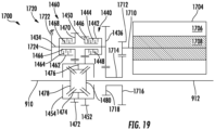
- an example not encompassed by the wording of the claims of a two-speed electric drive axle 1400 may comprise an integrated drive system.
- the electric drive axle 1400 is a two-speed variant of the electric drive axle 900 depicted in FIG. 11 .
- components shared by the electric drive axles 900 and 1400 are given like reference numbers.
- the electric drive axle 1400 comprises a two-speed electric drive axle system having a single planetary gear system 920 as described in relation to the electric drive axle 900. Additionally, the electric drive axle 1400 comprises a layshaft 1434 having first and second engagement elements 1440, 1460.
- the first and second engagement elements 1440, 1460 may comprise a wet clutch powershift design such that during the engagement/disengagement of the first and second engagement elements 1440, 1460 torque can be transferred without a power drop to zero.
- the first and second engagement elements 1440, 1460 may comprise a synchronizer system.
- the first and second engagement elements 1440, 1460 may comprise a first and second dog clutch.
- the first and second engagement elements 1440, 1460 may be referred to herein as a shift element.
- the layshaft 1434 is disposed generally parallel to the axle half shafts 910, 912.
- the layshaft 1434 includes an input gear 1436 disposed thereon and in meshed engagement with the driven gear 932.
- the first engagement element 1440 is disposed concentric with the layshaft 1434 and adjacent to the input gear 1436.
- the first engagement element 1440 comprises a clutch drum 1442 coupled with the layshaft 1434 for rotation therewith.
- the clutch drum 1442 comprises a plurality of radially inward extending clutch plates 1444.
- the clutch plates 1444 are coupled with the clutch drum 1442 for axial movement therealong.
- the first engagement element 1440 also comprises a clutch hub 1446 concentrically disposed about the layshaft 1434.
- the clutch hub 1446 comprises a plurality of radially outward extending clutch plates 1448 interleaved with the clutch plates 1444.
- the clutch plates 1448 are connected to the clutch hub 1446 for axial movement therealong.
- the clutch hub 1446 is selectively rotatable with regard to the layshaft 1434.
- the clutch hub 1446 further comprises a hub gear 1450.
- the hub gear 1450 is in meshed engagement with a first gear 1452.
- the first gear 1452 is coupled for rotation with a differential case 1454.
- the second engagement element 1460 is also disposed concentric with the layshaft 1434 adjacent to the first engagement element 1440.
- the second engagement element 1460 comprises a clutch drum 1462 coupled with the layshaft 1434 for rotation therewith.
- the clutch drum 1462 comprises a plurality of radially inward extending clutch plates 1464.
- the clutch plates 1464 are coupled with the clutch drum 1462 for axial movement therealong.
- the second engagement element 1460 also comprises a clutch hub 1466 concentrically disposed about the layshaft 1434.
- the clutch hub 1466 comprises a plurality of radially outward extending clutch plates 1468 interleaved with the clutch plates 1464.
- the clutch plates 1468 are connected to the clutch hub 1466 for axial movement therealong.
- the clutch hub 1466 is selectively rotatable with regard to the layshaft 1434.
- the clutch hub 1466 further comprises a hub gear 1470.
- the hub gear 1470 is in meshed engagement with a second gear 1472.
- the second gear 1472 is coupled for rotation with the differential case 1454.
- the differential case 1454 is selectively driven via the first gear 1452 or the second gear 1472.
- Two or more differential pinions 1474 are coupled within the differential case 1454 via a pinion shaft 1476 (i.e., spider shaft).
- the pinion shaft 1476 may comprise a cross member.
- the differential pinions 1474 are in meshed engagement with a pair of side gears 1478, 1480.
- the side gears 1478, 1480 are coupled for rotation with the drive axle half shafts 910, 912, respectively.
- a first engagement element actuator selectively compresses the plurality of clutch plates 1444, 14448 in the first engagement element 1440 to lock the clutch plates 1444, 1448 together. Compression of the clutch plates 1444, 1448 causes them to rotate together. When the first engagement element actuator relaxes, or releases, the compression, the clutch plates 1444, 1448 rotate with respect to one another.
- the first engagement element actuator may be such as an electromagnetic actuator, a hydraulic actuator, a pneumatic actuator, or a mechanical actuator.
- a second engagement element actuator selectively compresses the plurality of clutch plates 1464, 1468 in the second engagement element 1460 to lock them together. Compression of the clutch plates 1464, 1468 causes them to rotate together. When the second engagement element actuator relaxes, or releases, the compression, the clutch plates 1464, 1468 rotate with respect to one another.
- the second engagement element actuator may be such as an electromagnetic actuator, a hydraulic actuator, a pneumatic actuator, or a mechanical actuator.
- the first and second engagement element actuators work independently of one another.
- the gear ratio of the second clutch hub gear 1470 and the second gear 1472 is different from the gear ratio of the first clutch hub gear 1450 and the first gear 1452.
- first speed reduction mode the first engagement element 1440 is closed and the second engagement element 1460 is open.
- rotation is provided through the layshaft 1434, through the first engagement element 1440 to the gear ratio defined by the clutch hub gear 1450 and the first gear 1452 on the differential case 1454.
- second speed reduction mode the second engagement element 1460 is closed and the first engagement element 1440 is open.
- rotation is provided through the layshaft 1434, through the second engagement element 1460 to the gear ratio defined by the clutch hub gear 1470 and the second gear 1472 on the differential case 1454.
- a first layshaft gear and a second layshaft gear are disposed on the layshaft 1434.
- the first layshaft gear is in meshed engagement with the first drive gear 1452
- the second layshaft gear is in meshed engagement with the second drive gear 1472.
- the shift element couples the first layshaft gear with the layshaft 1434 to transfer torque from the layshaft 1434 to the first drive gear 1452.
- the shift element couples the second layshaft gear with the layshaft 1434 to transfer torque from the layshaft 1434 to the second drive gear 1472.
- an example not encompassed by the wording of the claims of a two-speed electric drive axle 1500 may comprise an integrated drive system.
- the electric drive axle 1500 includes an electric motor 1504 that is radially concentric with one of a pair of axle half shafts 1510, 1512 extending from a differential 1514.
- the electric motor 1504 comprises a stator 1506 and a rotor 1508.
- the electric drive axle 1500 may comprise an inverter (not depicted) for converting direct current to alternating current when the electric motor 1504 is utilized to drive the vehicle, and for converting alternating current to direct current when the vehicle decelerates.
- the electric drive axle 1500 comprises a single planetary gear system 1520.
- a driving shaft 1518 is coupled with the rotor 1508 for rotation therewith.
- the driving shaft 1518 is coupled for rotation with a sun gear 1522 disposed at an inboard end thereof.
- the sun gear 1522 inputs driving rotation to the planetary gear system 1520.
- a plurality of planet gears 1524 are in meshed engagement with the sun gear 1522, and are driven thereby.
- the planet gears 1524 are also in meshed engagement with a planetary ring gear 1526.
- the planetary ring gear 1526 may comprise a stationary housing portion or an independent component fixedly coupled with the stationary housing.
- the planet gears 1524 are carried by a planet carrier 1528.
- the planet carrier 1528 comprises a driven shaft 1530 concentrically disposed about the axle half shaft 1512.
- a first engagement element 1532 is disposed concentric with the driven shaft 1530.
- the first engagement element 1532 comprises a clutch drum 1534 coupled with the driven shaft 1530 for rotation therewith.
- the clutch drum 1534 comprises a plurality of radially inward extending clutch plates 1536.
- the clutch plates 1536 are coupled with the clutch drum 1534 for axial movement therealong.
- the first engagement element 1532 also comprises a clutch hub 1538 concentrically disposed about the driven shaft 1530.
- the clutch hub 1538 comprises a plurality of radially outward extending clutch plates 1540 interleaved with the clutch plates 1536.
- the clutch plates 1540 are connected to the clutch hub 1538 for axial movement therealong.
- the clutch hub 1538 is selectively rotatable with regard to the driven shaft 1530.
- the clutch hub 1538 further comprises a hub gear 1542.
- the hub gear 1542 is in meshed engagement with a first layshaft gear 1544.
- the first layshaft gear 1544 is coupled for rotation with a layshaft 1546.
- a second engagement element 1550 is also disposed concentric with the driven shaft 1530, and is located adjacent to the first engagement element 1532.
- the second engagement element 1550 comprises a clutch drum 1552 coupled with the driven shaft 1530 for rotation therewith.
- the clutch drum 1552 comprises a plurality of radially inward extending clutch plates 1554.
- the clutch plates 1554 are coupled with the clutch drum 1552 for axial movement therealong.
- the second engagement element 1550 also comprises a clutch hub 1556 concentrically disposed about the driven shaft 1530.
- the clutch hub 1556 comprises a plurality of radially outward extending clutch plates 1558 interleaved with the clutch plates 1554.
- the clutch plates 1558 are connected to the clutch hub 1556 for axial movement therealong.
- the clutch hub 1556 is selectively rotatable with regard to the driven shaft 1530.
- the clutch hub 1556 also comprises a hub gear 1560.
- the hub gear 1560 is in meshed engagement with a second layshaft gear 1562.
- the second layshaft gear 1562 is coupled for rotation with the layshaft 1546.
- the layshaft 1546 is disposed offset from, and parallel with, the drive axle half shafts 1510, 1512.
- the layshaft 1546 comprises the first layshaft gear 1544 which is in meshed engagement with the first clutch hub gear 1542 to create a first gear ratio.
- the layshaft 1546 also comprises the second layshaft gear 1562 which is in meshed engagement with the second clutch hub gear 1560 to create a second gear ratio.
- the layshaft 1546 further comprises a third layshaft gear 1564 in meshed engagement with a gear 1566 coupled with a differential case 1568.
- a first engagement element actuator selectively compresses the plurality of clutch plates 1536, 1540 in the first engagement element 1532 to lock the clutch plates 1536, 1540 together. Compression of the clutch plates 1536, 1540 causes them to rotate together. When the first engagement element actuator relaxes, or releases, the compression, the clutch plates 1536, 1540 rotate with respect to one another.
- the first engagement element actuator may be such as an electromagnetic actuator, a hydraulic actuator, a pneumatic actuator, or a mechanical actuator.
- a second engagement element actuator selectively compresses the plurality of clutch plates 1554, 1558 in the second engagement element 1550 to lock them together. Compression of the clutch plates 1554, 1558 causes them to rotate together. When the second engagement element actuator relaxes, or releases, the compression, the clutch plates 1554, 1558 rotate with respect to one another.
- the second engagement element actuator may be such as an electromagnetic actuator, a hydraulic actuator, a pneumatic actuator, or a mechanical actuator.
- the first and second engagement element actuators work independently of one another.
- first speed reduction mode In a first speed reduction mode the first engagement element 1532 is closed and the second engagement element 1550 is open. In the first speed reduction mode, rotation is provided through the planetary gear system 1520, through the first engagement element 1532, through the first gear ratio defined by the first clutch hub gear 1542 and the first layshaft gear 1544, and through the third layshaft gear 1564 to the gear 1566 on the differential case 1568.
- second speed reduction mode the second engagement element 1550 is closed and the first engagement element 1532 is open.
- rotation is provided through the planetary gear system 1520, through the second engagement element 1550, through the second gear ratio defined by the second clutch hub gear 1560 and the second layshaft gear 1562, and through the third layshaft gear 1564 to the drive gear 1566 on the differential case 1568.
- the differential case 1568 is driven via the third layshaft gear 1564.
- Two or more differential pinions 1570 are coupled within the differential case 1568 via a pinion shaft 1572 (i.e., spider shaft).
- the pinion shaft 1572 may comprise a cross member.
- the differential pinions 1570 are in meshed engagement with a pair of side gears 1574, 1576.
- the side gears 1574, 1576 are coupled for rotation with the drive axle half shafts 1510, 1512, respectively.
- the first and second engagement elements 1532, 1550 may comprise a synchronizer system. In still another example not encompassed by the wording of the claims, the first and second engagement elements 1532, 1550 may comprise a first and second dog clutch. The first and second engagement elements 1532, 1550 may be referred to herein as a shift element.
- a first driving gear and a second driving gear are disposed on the driven shaft 1530. The first driving gear is in meshed engagement with the first layshaft gear 1544, and the second driving gear is in meshed engagement with the second layshaft gear 1562.
- the shift element couples the first driving gear with the driven shaft 1530 to transfer torque from the driven shaft 1530 to the first layshaft gear 1544. In a second position, the shift element couples the second driving gear with the driven shaft 1530 to transfer torque from the driven shaft 1530 to the second layshaft gear 1562.
- an embodiment of a two-speed electric drive axle 1600 may comprise an integrated drive system.
- FIG. 18 illustrates an embodiment of the claimed invention.
- the electric drive axle 1600 is a two-speed variant of the electric drive axle 1000 depicted in FIG. 12 .
- components shared by the electric drive axles 1600 and 1000 are given like reference numbers.
- the electric drive axle 1600 includes an electric motor 1004 that is disposed offset from of a pair of axle half shafts 1010, 1012 extending from a differential 1014.
- the electric motor 1004 comprises a stator 1006 and a rotor 1008.
- the electric drive axle 1600 may comprise an inverter (not depicted) for converting direct current to alternating current when the electric motor 1004 is utilized to drive the vehicle, and for converting alternating current to direct current when the vehicle decelerates.
- a driving shaft 1018 is coupled with the rotor 1008 for rotation therewith.
- a first engagement element 1610 is disposed concentric with the driving shaft 1018.
- the first engagement element 1610 comprises a clutch drum 1612 coupled with the driving shaft 1018 for rotation therewith.
- the clutch drum 1612 comprises a plurality of radially inward extending clutch plates 1614.
- the clutch plates 1614 are coupled with the clutch drum 1612 for axial movement therealong.
- the first engagement element 1610 also comprises a clutch hub 1616 concentrically disposed about the driving shaft 1018.
- the clutch hub 1616 comprises a plurality of radially outward extending clutch plates 1618 interleaved with the clutch plates 1614.
- the clutch plates 1618 are connected to the clutch hub 1616 for axial movement therealong.
- the clutch hub 1616 is selectively rotatable with regard to the driving shaft 1018.
- the clutch hub 1616 further comprises a hub gear 1620.
- the hub gear 1620 is in meshed engagement with a first driven gear 1624.
- the first driven gear 1624 is coupled for rotation with a driven shaft 1622.
- a second engagement element 1630 is also disposed concentric with the driving shaft 1018, and is located adjacent to the first engagement element 1610.
- the second engagement element 1630 comprises a clutch drum 1632 coupled with the driving shaft 1018 for rotation therewith.
- the clutch drum 1632 comprises a plurality of radially inward extending clutch plates 1634.
- the clutch plates 1634 are coupled with the clutch drum 1632 for axial movement therealong.
- the second engagement element 1630 also comprises a clutch hub 1636 concentrically disposed about the driving shaft 1018.
- the clutch hub 1636 comprises a plurality of radially outward extending clutch plates 1638 interleaved with the clutch plates 1618.
- the clutch plates 1638 are connected to the clutch hub 1636 for axial movement therealong.
- the clutch hub 1636 is selectively rotatable with regard to the driving shaft 1018.
- the clutch hub 1636 also comprises a hub gear 1640.
- the hub gear 1640 is in meshed engagement with a second driven gear 1642.
- the second driven gear 1642 is coupled for rotation with the driven shaft 1622.
- the driven shaft 1622 is disposed concentrically about the drive axle half shaft 1010.
- the driven shaft 1622 comprises the first driven gear 1624 which is in meshed engagement with the first clutch hub gear 1620 to create a first gear ratio.
- the driven shaft 1622 also comprises the second driven gear 1642 which is in meshed engagement with the second clutch hub gear 1640 to create a second gear ratio.
- a third driven gear 1644 is coupled with the driven shaft 1622 for rotation therewith.
- the third driven gear 1644 is in meshed engagement with a first layshaft gear 1028 coupled with a layshaft 1030 for rotation therewith.
- the layshaft 1030 is disposed offset from, and parallel to, the axle half shafts 1010, 1012.
- the first layshaft gear 1028 is coupled with the layshaft 1030 for rotation therewith.
- the layshaft 1030 may be disposed coaxially with the driving shaft 1018.
- a second layshaft gear 1032 is disposed on the layshaft 1030 opposite the first layshaft gear 1028, and is coupled with the layshaft 1030 for rotation therewith.
- the second layshaft gear is in meshed engagement with a drive gear 1040.
- the drive gear 1040 is fixedly coupled with a differential case 1042.
- the differential case 1042 is rotatably driven via the drive gear 1040.
- Two or more differential pinions 1044 are coupled within the differential case 1042 via a pinion shaft 1046 (i.e., spider shaft).
- the pinion shaft 1046 may comprise a cross member.
- the differential pinions 1044 are in meshed engagement with a pair of side gears 1048, 1050.
- the side gears 1048, 1050 are coupled for rotation with the drive axle half shafts 1010, 1012, respectively.
- a first engagement element actuator selectively compresses the plurality of clutch plates 1614, 1618 in the first engagement element 1610 to lock the clutch plates 1614, 1618 together. Compression of the clutch plates 1614, 1618 causes them to rotate together. When the first engagement element actuator relaxes, or releases, the compression, the clutch plates 1614, 1618 rotate with respect to one another.
- the first engagement element actuator may be such as an electromagnetic actuator, a hydraulic actuator, a pneumatic actuator, or a mechanical actuator.
- a second engagement element actuator selectively compresses the plurality of clutch plates 1634, 1638 in the second engagement element 1630 to lock them together. Compression of the clutch plates 1634, 1638 causes them to rotate together. When the second engagement element actuator relaxes, or releases, the compression, the clutch plates 1634, 1638 rotate with respect to one another.
- the second engagement element actuator may be such as an electromagnetic actuator, a hydraulic actuator, a pneumatic actuator, or a mechanical actuator.
- the first and second engagement element actuators work independently of one another.
- first speed reduction mode In a first speed reduction mode the first engagement element 1610 is closed and the second engagement element 1630 is open. In the first speed reduction mode, rotation is provided through the driving shaft 1018, through the first engagement element 1610, through the first gear ratio defined by the first clutch hub gear 1620 and the first driven gear 1624, through the third driven gear 1644 and the first layshaft gear 1028, and through the second layshaft gear 1032 to the drive gear 1040 and the differential 1014.
- second speed reduction mode In a second speed reduction mode the second engagement element 1630 is closed and the first engagement element 1610 is open.
- rotation is provided through the driving shaft 1018, through the second engagement element 1630, through the second gear ratio defined by the second clutch hub gear 1640 and the second driven gear 1642, through the third driven gear 1644 and the first layshaft gear 1028, and through the second layshaft gear 1032 to the drive gear 1040 and the differential 1014.
- the first and second engagement elements 1610, 1630 may comprise a synchronizer system. In still another embodiment, the first and second engagement elements 1610, 1630 may comprise a first and second dog clutch.
- the first and second engagement elements 1610, 1630 may be referred to herein as a shift element.
- a first driving gear and a second driving gear are disposed on the driving shaft 1018. The first driving gear is in meshed engagement with the first driven gear 1624, and the second driving gear is in meshed engagement with the second driven gear 1642. In a first position, the shift element couples the first driving gear with the driving shaft 1018 to transfer torque from the driving shaft 1018 to the first driven gear 1624. In a second position, the shift element couples the second driving gear with the driving shaft 1018 to transfer torque from the driving shaft 1018 to the second driven gear 1642.
- an example not encompassed by the wording of the claims of a two-speed electric drive axle 1700 may comprise an integrated drive system.
- the electric drive axle 1700 is a variant of the electric drive axle 1400 depicted in FIG. 16 .
- the electric drive axle 1700 does not include a reduction through a planetary gear system between the electric motor 904 and the differential case 1454.
- the electric drive axle 1700 may include a parking brake 1720.
- components shared by the electric drive axles 1700 and 1400 are given like reference numbers.
- the electric drive axle 1700 comprises an electric motor/generator 1704 disposed offset from drive axle shafts 910, 912.
- the electric motor/generator comprises a stator 1706 and a rotor 1708.
- a driving shaft 1710 is disposed generally parallel with the drive axle shafts 910, 912, and is drivingly engaged with the rotor 1708.
- a driving gear 1712 is coupled with the driving shaft 1710 for rotation therewith.
- the driving shaft 1710 transfers torque to driven shaft 1714 disposed concentrically about the drive axle shaft 912 via the meshed engagement of the driving gear 1712 and a first driven gear 1716.
- the first driven gear 1716 is coupled with the driven shaft 1714 for rotation therewith.
- a second driven gear 1718 is coupled with the driven shaft 1714 opposite the first driven gear 1716.
- the driven shaft 1714 transfers torque to a layshaft 1434 having first and second engagement elements 1440, 1460, via the meshed engagement of the second driven gear 1718 and a layshaft input gear 1436.
- the layshaft 1434 is disposed generally parallel to the axle half shafts 910, 912.
- the first engagement element 1440 is disposed concentric with the layshaft 1434 and adjacent to the input gear 1436.
- the first engagement element 1440 comprises a clutch drum 1442 coupled with the layshaft 1434 for rotation therewith.
- the clutch drum 1442 comprises a plurality of radially inward extending clutch plates 1444.
- the clutch plates 1444 are coupled with the clutch drum 1442 for axial movement therealong.
- the first engagement element 1440 also comprises a clutch hub 1446 concentrically disposed about the layshaft 1434.
- the clutch hub 1446 comprises a plurality of radially outward extending clutch plates 1448 interleaved with the clutch plates 1444.
- the clutch plates 1448 are connected to the clutch hub 1446 for axial movement therealong.
- the clutch hub 1446 is selectively rotatable with regard to the layshaft 1434.
- the clutch hub 1446 further comprises a hub gear 1450.
- the hub gear 1450 is in meshed engagement with a first gear 1452.
- the first gear 1452 is coupled for rotation with a differential case 1454.
- the second engagement element 1460 is also disposed concentric with the layshaft 1434 adjacent to the first engagement element 1440.
- the second engagement element 1460 comprises a clutch drum 1462 coupled with the layshaft 1434 for rotation therewith.
- the clutch drum 1462 comprises a plurality of radially inward extending clutch plates 1464.
- the clutch plates 1464 are coupled with the clutch drum 1462 for axial movement therealong.
- the second engagement element 1460 also comprises a clutch hub 1466 concentrically disposed about the layshaft 1434.
- the clutch hub 1466 comprises a plurality of radially outward extending clutch plates 1468 interleaved with the clutch plates 1464.
- the clutch plates 1468 are connected to the clutch hub 1466 for axial movement therealong.
- the clutch hub 1466 is selectively rotatable with regard to the layshaft 1434.
- the clutch hub 1466 further comprises a hub gear 1470.
- the hub gear 1470 is in meshed engagement with a second gear 1472.
- the second gear 1472 is coupled for rotation with the differential case 1454.
- the differential case 1454 is selectively driven via the first gear 1452 or the second gear 1472.
- Two or more differential pinions 1474 are coupled within the differential case 1454 via a pinion shaft 1476 (i.e., spider shaft).
- the pinion shaft 1476 may comprise a cross member.
- the differential pinions 1474 are in meshed engagement with a pair of side gears 1478, 1480.
- the side gears 1478, 1480 are coupled for rotation with the drive axle half shafts 910, 912, respectively.
- a first engagement element actuator selectively compresses the plurality of clutch plates 1444, 14448 in the first engagement element 1440 to lock the clutch plates 1444, 1448 together. Compression of the clutch plates 1444, 1448 causes them to rotate together. When the first engagement element actuator relaxes, or releases, the compression, the clutch plates 1444, 1448 rotate with respect to one another.
- the first engagement element actuator may be such as an electromagnetic actuator, a hydraulic actuator, a pneumatic actuator, or a mechanical actuator.
- a second engagement element actuator selectively compresses the plurality of clutch plates 1464, 1468 in the second engagement element 1460 to lock them together. Compression of the clutch plates 1464, 1468 causes them to rotate together. When the second engagement element actuator relaxes, or releases, the compression, the clutch plates 1464, 1468 rotate with respect to one another.
- the second engagement element actuator may be such as an electromagnetic actuator, a hydraulic actuator, a pneumatic actuator, or a mechanical actuator.
- the first and second engagement element actuators work independently of one another.
- the gear ratio of the second clutch hub gear 1470 and the second gear 1472 is different from the gear ratio of the first clutch hub gear 1450 and the first gear 1452.
- first speed reduction mode the first engagement element 1440 is closed and the second engagement element 1460 is open.
- rotation is provided through the layshaft 1434, through the first engagement element 1440 to the gear ratio defined by the clutch hub gear 1450 and the first gear 1452 on the differential case 1454.
- second speed reduction mode the second engagement element 1460 is closed and the first engagement element 1440 is open.
- rotation is provided through the layshaft 1434, through the second engagement element 1460 to the gear ratio defined by the clutch hub gear 1470 and the second gear 1472 on the differential case 1454.
- the first and second engagement elements 1440, 1460 may comprise a synchronizer system. In still another example not encompassed by the wording of the claims, the first and second engagement elements 1440, 1460 may comprise a first and second dog clutch. The first and second engagement elements 1440, 1460 may be referred to herein as a shift element. In an example not encompassed by the wording of the claims, not disposed, a first layshaft gear and a second layshaft gear are disposed on the layshaft 1434. The first layshaft gear is in meshed engagement with the first drive gear 1452, and the second layshaft gear is in meshed engagement with the second drive gear 1472.
- the shift element couples the first layshaft gear with the layshaft 1434 to transfer torque from the layshaft 1434 to the first drive gear 1452.
- the shift element couples the second layshaft gear with the layshaft 1434 to transfer torque from the layshaft 1434 to the second drive gear 1472.
- the parking brake 1720 comprises a first portion 1722 coupled with a stationary housing portion of the electric drive axle 1700 and a second portion 1724 coupled with the layshaft 1434.
- the parking brake first portion 1722 selectively engages the second portion 1724 to mitigate rotation of the layshaft 1434, and therefore the electric drive axle 1700.
- the parking brake 1720 may comprise any shift element suitable for selectively engaging the stationary housing and the layshaft 1434.
- the parking brake 1720 may comprise a multi-plate clutch.
- the parking brake 1720 may comprise a dog clutch.
Landscapes
- Engineering & Computer Science (AREA)
- Chemical & Material Sciences (AREA)
- Combustion & Propulsion (AREA)
- Transportation (AREA)
- Mechanical Engineering (AREA)
- Retarders (AREA)
- Hybrid Electric Vehicles (AREA)
- Arrangement Of Transmissions (AREA)
- Structure Of Transmissions (AREA)
Description
- The present disclosure relates to electric drive axles and more particularly to powerpaths for an electric axle.
- Electric and hybrid-electric vehicles utilize an electric power source in communication with an electric motor to provide drive, or augmented drive, to the vehicle. Electric vehicles have several characteristics superior to conventional internal combustion engine driven vehicles. For example, electric motors produce fewer vibrations than internal combustion engines, and electric motors achieve maximum torque more quickly than internal combustion engines.
- However, conventional electric vehicles utilize a drive axle driven by an electric motor without a gearbox. In order for the conventional electric vehicle to achieve sufficient speed, the electric motor must allow for reasonable power over a broad speed range. An electric motor which can provide reasonable power over a broad speed range is typically large and heavy.
- In view of the above, there remains a need for an electric drive axle that does not require a broad speed range, such that the electric motor may be reduced in size and weight. The present disclosure provides, inter alia, an electric drive axle having reduced size, weight, and production costs. Prior art document
EP 1 526 027 A2 relates to a power transmission apparatus for vehicles. The power transmission apparatus comprises a motor, a reduction gear unit for decelerating power outputted from the motor, and a differential gear unit for distributing the power decelerated by the reduction gear unit to left and right wheels. The reduction gear unit is a reduction gear mechanism including a plurality of gears mounted over a shaft, which is rotatably held by a housing in a fixed position. This document does not relate to a shift element having a first position, wherein a first driving gear is coupled for rotation with a driving shaft, and a second position wherein a second driving gear is coupled for rotation with a driving shaft. Further prior art can be found, e.g., in documentsDE 10 2010 024603 A1 andFR 2 805 221 A1 - The invention is defined by the claims. The present invention relates to an electric drive axle. The claimed electric drive axle comprises: a first axle shaft; a second axle shaft coaxial with said first axle shaft; a differential apparatus having a differential case, wherein said differential apparatus operatively connects said first and second axle shafts; an electric motor having a stator and a rotor; a driving shaft coupled for rotation with said rotor disposed parallel with said first axle shaft; a first driving gear disposed on said driving shaft; a driven shaft having a first driven gear and a second driven gear, wherein said first driven gear meshes with said first driving gear; a layshaft disposed parallel with said first axle shaft; a first layshaft gear coupled with said layshaft and meshed with said second driven gear; a second layshaft gear disposed on said layshaft; and a first drive gear coupled with said differential case and in meshed engagement with said second layshaft gear. The claimed electric drive axle further comprises: a third driven gear coupled with said driven shaft; a second driving gear disposed on said driving shaft and in meshed engagement with said third driven gear; and a shift element having a first position wherein said first driving gear is coupled for rotation with said driving shaft, and a second position wherein said second driving gear is coupled for rotation with said driving shaft.
- The accompanying drawings are incorporated herein as part of the specification. The drawings described herein illustrate embodiments of the presently disclosed subject matter, and are illustrative of selected principles and teachings of the present disclosure. However, the drawings do not illustrate all possible implementations of the presently disclosed subject matter, and are not intended to limit the scope of the present disclosure in any way.
-
FIG. 1 schematically depicts of a two speed electric drive axle system according to an example not encompassed by the wording of the claims; -
FIG. 2 schematically depicts a two speed electric drive axle system according to another example not encompassed by the wording of the claims; -
FIG. 3 schematically depicts the two speed electric drive axle system according toFIG. 2 having a stepped pinion planetary gear set; -
FIG. 4 schematically depicts a two speed electric drive axle system according toFIG. 2 having a double pinion planetary gear set; -
FIG. 4A schematically depicts a portion of the double pinion planetary gear set ofFIG. 4 , according to an example not encompassed by the wording of the claims; -
FIG. 5 schematically depicts a two speed electric drive axle system according to another example not encompassed by the wording of the claims; -
FIG. 6 schematically depicts a two speed electric drive axle system according to another example not encompassed by the wording of the claims; and -
FIG. 7 schematically depicts a one speed electric drive axle system according to another example not encompassed by the wording of the claims; -
FIG. 8 schematically depicts a one-speed electric drive axle system according to another example not encompassed by the wording of the claims; -
FIG. 9 schematically depicts a one-speed electric drive axle system according to another example not encompassed by the wording of the claims; -
FIG. 10 schematically depicts a one-speed electric drive axle system according to another example not encompassed by the wording of the claims; -
FIG. 11 schematically depicts a one-speed electric drive axle system according to another example not encompassed by the wording of the claims; -
FIG. 12 schematically depicts a one-speed electric drive axle system according to another example not encompassed by the wording of the claims; -
FIG. 13 schematically depicts a two-speed electric drive axle system according to an example not encompassed by the wording of the claims; -
FIG. 14 schematically depicts a two-speed electric drive axle system according to another example not encompassed by the wording of the claims; -
FIG. 15 schematically depicts a two-speed electric drive axle system according to another example not encompassed by the wording of the claims; -
FIG. 16 schematically depicts a two-speed electric drive axle system according to another example not encompassed by the wording of the claims; -
FIG. 17 schematically depicts a two-speed electric drive axle system according to another example not encompassed by the wording of the claims; -
FIG. 18 schematically depicts a two-speed electric drive axle system according to an embodiment of the invention; and -
FIG. 19 schematically depicts a two-speed electric drive axle system according to another example not encompassed by the wording of the claims. - The invention is defined by the claims. Also, although they may not be, like elements in various embodiments described herein may be commonly referred to with like reference numerals within this section of the application.
- Embodiments of an electric drive axle are described below. In certain embodiments, the electric drive axle is utilized with a pure electric vehicle (not depicted) where the electric drive axle is the only driving axle. In other embodiments, the electric drive axle is utilized with a hybrid four-wheel-drive vehicle (not depicted) where the front axle is driven by an internal combustion engine, and the rear axle is the electric drive axle (or vice versa). In still other embodiments, the electric drive axle is utilized in a hybrid commercial vehicle (not depicted) comprising a tandem axle in which the front tandem axle is driven by an internal combustion engine, and the rear tandem axle is the electric drive axle (or vice versa). The electric drive axle may have applications in commercial vehicles, both light duty and heavy duty vehicles, and for passenger, off-highway, and sport utility vehicles. Additionally, the electric drive axle described herein may be adapted for use in front and/or rear driving axles, and in steerable and non-steerable axles. It would be understood by one of ordinary skill in the art that the electric drive axle also has industrial, locomotive, military, agricultural, and aerospace applications.
- The embodiments of an electric drive axle may be described herein utilizing the terms "driven shaft" and "driving shaft." A person having skill in the art will recognize that in a regeneration mode, the driven shafts are driving, and the driving shafts are driven.
- The electric drive axle powerpaths disclosed herein can be divided into two distinct classes, one-speed and two-speed. In a one-speed embodiment, an electric drive axle couples an electric motor with a differential case without any shifting capability. In a two-speed embodiment, an electric drive axle comprises a shifting capability, which may be indicated as a two-speed gearbox. The one-speed and two-speed electric drive axles of the presently disclosed subject matter may also comprise a mechanical differential lock (not depicted) and a parking brake/pawl.
- As illustrated in
FIG. 1 , in an example not encompassed by the wording of the claims, anelectric drive axle 100 may comprise an integrated drive system. In an example not encompassed by the wording of the claims, theelectric drive axle 100 includes a two-speed gearbox 102 and an electric motor 104 (e.g., electromotor). Theelectric drive axle 100 also comprises a drive axle having a pair ofside shafts differential apparatus 114. Additionally, theelectric drive axle 100 comprises an inverter (not depicted) for converting direct current to alternating current when theelectric motor 104 is utilized to drive the vehicle, and for converting alternating current to direct current when the vehicle decelerates. Theelectric drive axle 100 also comprises ashifting mechanism 116. - In addition, the
electric drive axle 100 includes cooling fluid (not depicted) such as, but not limited to, automatic transmission fluid or axle oil integrated with theelectric drive axle 100 lubricant for cooling theelectric motor 104 and the inverter. In another example not encompassed by the wording of the claims (not depicted), the cooling fluid for theelectric motor 104 and the inverter may not be integrated with the axle oil. - The two-
speed gearbox 102 enables theelectric drive axle 100 to utilize theelectric motor 104 having a compact speed range, as compared to conventional electric motors. Because theelectric motor 104 has a compact speed range, it may be smaller than a conventional electric motor, and it may use less expensive material and fewer rare materials than a conventional electric motor. In an example not encompassed by the wording of the claims, theelectric motor 104 is a permanent magnet synchronous machine comprising astator 106 disposed concentrically about arotor 108. - A driving shaft 118 is coupled with the
rotor 108 for rotation therewith. In an example not encompassed by the wording of the claims, the driving shaft 118 comprises an end havinggear teeth 120. In another example not encompassed by the wording of the claims, thegear teeth 120 may comprise a gear coupled for rotation with the driving shaft 118. The driving shaft 118 is in driving engagement with a layshaft 122 of the two-speed gearbox 102 via thegear teeth 120. Thegear teeth 120 are in meshed engagement with agear 124 disposed on the layshaft 122. - A first gear 128 and a
second gear 130 are disposed concentrically about a portion of the layshaft 122. The first andsecond gears 128, 130 are selectively, and independently, drivingly engaged with the layshaft 122 via theshifting mechanism 116. A drivenshaft 132 is disposed about theaxle half shaft 112 coaxial with the driving shaft 118. A first driven gear 134 is coupled with the drivenshaft 132 for rotation therewith. The first driven gear 134 is in constant meshed engagement with the first gear 128 to create a first gear ratio. A second drivengear 136 is also coupled with the drivenshaft 132 for rotation therewith. The second drivengear 136 is in constant meshed engagement with thesecond gear 130 to create a second gear ratio. - In an example not encompassed by the wording of the claims, the
shift element 116 may be a synchronizer. In another example not encompassed by the wording of the claims, theshift element 116 may be a dog clutch. In yet another example not encompassed by the wording of the claims, theshift element 116 may be a pair of wet clutches. When theshift element 116 is actuated such that theshift element 116 drivingly engages the layshaft 122 with the first gear 128, thegear box 102 is placed in a first speed reduction mode. When theshift element 116 is actuated such that theshift element 116 drivingly engages the layshaft 122 with thesecond gear 130, thegear box 102 is placed in a second speed reduction mode. - Simultaneously engaging both the first and
second gears 128, 130 with the layshaft 122 via theshift element 116 locks thegearbox 102, and there is no rotation through theelectric drive axle 100. Simultaneously engaging the first andsecond gears 128, 130 with the layshaft 122 may be utilized as a parking brake, or as a supplement to a conventional parking brake. - The two-
speed gearbox 102 further comprises aplanetary gear system 140 disposed between thedifferential apparatus 114 and theelectric motor 104. Theplanetary gear system 140 comprises asun gear 142 coupled for rotation with the drivenshaft 132. A plurality of planet gears 144 are in meshed engagement with thesun gear 142, and are driven thereby. The planet gears 144 are also in meshed engagement with a source for ground, such as astationary housing 146. In an example not encompassed by the wording of the claims, thestationary housing 146 comprises a locked planetary ring gear. In addition, the planet gears 144 are carried by aplanet carrier 148 coupled for rotation with adifferential case 150. - The
differential apparatus 114 comprises two or moredifferential pinions 152. Thedifferential pinions 152 are coupled with thedifferential case 150 via a pinion shaft 154 (i.e., spider shaft). In an example not encompassed by the wording of the claims, thepinion shaft 154 may comprise a cross member. Thedifferential pinions 152 are in meshed engagement with a pair of side gears 156, 158 coupled for rotation with the driveaxle half shafts - As illustrated in
FIG. 2 , in another example not encompassed by the wording of the claims, anelectric drive axle 200 may comprise an integrated drive system. Theelectric drive axle 200 includes a two-speed gearbox 202 and anelectric motor 204. Theelectric motor 204 comprises astator 206 and arotor 208. Theelectric drive axle 200 also comprises a drive axle having a pair ofside shafts differential apparatus 214. Additionally, theelectric drive axle 200 may comprise an inverter (not depicted) for converting direct current to alternating current when theelectric motor 204 is utilized to drive the vehicle, and for converting alternating current to direct current when the vehicle decelerates. - A driving
shaft 218 is coupled with therotor 208 for rotation therewith. In an example not encompassed by the wording of the claims, adriving gear 220 is coupled with the drivingshaft 218. In another example not encompassed by the wording of the claims, the drivingshaft 218 comprises an end havingdriving gear 220. The drivingshaft 218 is in driving engagement with alayshaft 222 of the two-speed gearbox 202 via thedriving gear 220. Thedriving gear 220 may be in meshed engagement with aspur gear 224 disposed on thelayshaft 222. - A
planetary gear system 226 is disposed on, and driven by, thelayshaft 222. Theplanetary gear system 226 comprises asun gear 228 in driving engagement with thelayshaft 222. A plurality of planet gears 230 are in meshed engagement with thesun gear 228, and are driven thereby. The planet gears 230 are also in meshed engagement with aplanetary ring gear 232. In addition, the planet gears 230 are carried by aplanet carrier 234 coupled for rotation with a drivenshaft 236. Theplanet carrier 234 extends on either side of the plurality of planet gears 230. - A
first engagement element 238 is disposed on thelayshaft 222 for selectively engaging thelayshaft 222 and theplanet carrier 234. In an example not encompassed by the wording of the claims, thefirst engagement element 238 may comprise a synchronizer apparatus. In another example not encompassed by the wording of the claims, thefirst engagement element 238 may comprise a dog clutch. In yet other example not encompassed by the wording of the claimss, thefirst engagement element 238 may comprise any shift element suitable for selectively engaging thelayshaft 222 and theplanet carrier 234. Thefirst engagement element 238 locks theplanetary gear system 226 such that theplanetary gear system 226 rotates without a reduction. In another example not encompassed by the wording of the claims, locking theplanetary gear system 226 may be realized by engaging two elements of theplanetary gear system 226, such as thesun gear 228,ring gear 232, orplanet carrier 234. - A
second engagement element 240 is coupled with astationary housing portion 242 of thegearbox 202. Thesecond engagement element 240 selectively engages theplanetary ring gear 232 to provide a source for ground for theplanetary gear system 226. Thesecond engagement element 240 may comprises any shift element suitable for selectively engaging thestationary housing 242 and theplanetary ring gear 232. In an example not encompassed by the wording of the claims, thesecond engagement element 240 may comprise a multi-plate clutch. In another example not encompassed by the wording of the claims, thesecond engagement element 240 may comprise a dog clutch. - In a first speed reduction mode, the
first engagement element 238 is operative to couple thelayshaft 222 and theplanet carrier 234, and thesecond engagement element 240 is inoperative such that theplanetary ring gear 232 rotates with the plurality of planet gears 230. In the first speed reduction mode, theplanet carrier 234 drives the drivenshaft 236 without a reduction through theplanetary gear system 226. - In a second speed reduction mode, the
first engagement element 238 is inoperative such that thelayshaft 222 drives thesun gear 228, and thesecond engagement element 240 is operative to lock theplanetary ring gear 232 to thestationary housing 242. In the second speed reduction mode, thesun gear 228 drives the plurality of planet gears 230 within theplanetary ring gear 232 and theplanet carrier 234 drives the drivenshaft 236 producing a reduction through theplanetary gear system 226. - If both the first and
second engagement elements gearbox 202 becomes locked and there is not rotation through theelectric drive axle 200. Simultaneously engaging the first andsecond engagement elements - A
gear 244 is disposed on the drivenshaft 236 for rotation therewith. Thegear 244 is in meshed engagement with agear 246 coupled with adifferential case 248. Two or moredifferential pinions 252 are coupled with thedifferential case 248 via a pinion shaft 254 (i.e., spider shaft). In an example not encompassed by the wording of the claims, thepinion shaft 254 may comprise a cross member. Thedifferential pinions 252 are in meshed engagement with a pair of side gears 256, 258 coupled for rotation with the driveaxle half shafts - In another example not encompassed by the wording of the claims, as illustrated in
FIG. 3 , theelectric drive axle 200 may comprise a stepped pinion planetary gear set 260. Utilizing a stepped pinion planetary gear set 260 enables a greater, or smaller,planetary ring gear 232 tosun gear 228 ratio. The stepped pinion planetary gear set 260 includes thesun gear 228 in driving engagement with a first set of planet gears 262. The first set of planet gears 262 is rotatably disposed on theplanet carrier 234. A second set of planet gears 264 is rotatably disposed on theplanet carrier 234 inboard of the first set of planet gears 262. The second set of planet gears 264 each have a smaller diameter than the first set of planet gears 262. In an example not encompassed by the wording of the claims, the second set of planet gears 264 each have a larger diameter than the first set of planet gears 262. The second set of planet gears 264 is in meshed engagement with theplanetary ring gear 232. The other elements of theelectric drive axle 200 operate as described above in relation toFIG. 2 . - As illustrated in
FIGS. 4 and4A , in an example not encompassed by the wording of the claims, theelectric drive axle 200 may comprise a double pinion planetary gear set 270. The double pinion planetary gear set 270 includes thesun gear 228 in driving engagement with a first set of planet gears 266. The first set of planet gears 266 is rotatably disposed on theplanet carrier 234 via corresponding pins thereon. A second set of planet gears 268 is rotatably disposed on theplanet carrier 234 radially outward of the first set of planet gears 266. The second set of planet gears 268 each have a greater diameter than the first set of planet gears 264. In an example not encompassed by the wording of the claims, the second set of planet gears 268 each have a smaller diameter than the first set of planet gears 264. The second set of planet gears 268 is in meshed engagement with theplanetary ring gear 232 and the first set of planet gears 266. InFIG. 4A , the first and second sets of planet gears 266, 268 are each illustrated as comprising three gears; however, the double pinion planetary gear set 270 is not limited thereto, and may comprise a greater or fewer number of planet gears. - The rotational direction of the
gear 244 disposed on the drivenshaft 236 is reversed when thesecond engagement element 240 is engaged and thefirst engagement element 238 is disengaged. To maintain the direction of rotation of the output, the rotational direction of theelectric motor 204 is reversed when thesecond engagement element 240 is engaged. The other elements of theelectric drive axle 200 operate as described above in relation toFIG. 2 . - As illustrated in
FIG. 5 , in another example not encompassed by the wording of the claims, anelectric drive axle 300 may comprise an integrated drive system having a similar geometry to theelectric drive axle 200. Theelectric drive axle 300 includes a two-speed gearbox 302 and anelectric motor 304. Theelectric motor 304 comprises astator 306 and arotor 308. Theelectric drive axle 300 also comprises a drive axle having a pair ofside shafts differential apparatus 314. Additionally, theelectric drive axle 300 may comprise an inverter (not depicted) for converting direct current to alternating current when theelectric motor 304 is utilized to drive the vehicle, and for converting alternating current to direct current when the vehicle decelerates. - A driving
shaft 318 is coupled with therotor 308 for rotation therewith. The drivingshaft 318 is coupled for rotation with agear 320 disposed at an inboard end thereof. The drivingshaft 318 is in driving engagement with alayshaft 322 of the two-speed gearbox 302 via thegear 320. Thegear 320 is in meshed engagement with a drivengear 324 disposed on thelayshaft 322. - A
planetary gear system 326 is disposed on, and driven by, thelayshaft 322. Theplanetary gear system 326 comprises asun gear 328 in driving engagement with thelayshaft 322. A plurality of planet gears 330 are in meshed engagement with thesun gear 328, and are driven thereby. The planet gears 330 are also in meshed engagement with aplanetary ring gear 332. In addition, the planet gears 330 are carried by aplanet carrier 334. Theplanet carrier 334 is selectively engageable with thelayshaft 322 for rotation therewith via afirst engagement element 338. - The
first engagement element 338 is disposed on thelayshaft 322 for selectively engaging thelayshaft 322 and theplanet carrier 334. Thefirst engagement element 338 may comprise a synchronizer, a dog clutch, a multi-plate clutch, or any shift element suitable for selectively engaging thelayshaft 322 and theplanet carrier 334. - A
second engagement element 340 is coupled with astationary housing portion 342 of thegearbox 302. Thesecond engagement element 340 selectively engages theplanet carrier 334 with thestationary housing 342. Thesecond engagement element 340 may comprise any shift element suitable for selectively engaging thestationary housing 342 and theplanet carrier 334. In an example not encompassed by the wording of the claims, thesecond engagement element 340 may comprise a multi-plate clutch. In other examples not encompassed by the wording of the claims, thesecond engagement element 340 may comprise a dog clutch, or a synchronizer. - In a first speed reduction mode, the
first engagement element 338 is operative to couple thelayshaft 322 and theplanet carrier 334, and thesecond engagement element 340 is inoperative such that theplanet carrier 334 rotates with the plurality of planet gears 330. In the first speed reduction mode, theplanet carrier 334 drives theplanetary ring gear 332, and theplanetary ring gear 332 drives a drivenshaft 336 coupled therewith without a reduction through theplanetary gear system 326. - In a second speed reduction mode, the
first engagement element 338 is inoperative such that thelayshaft 322 drives thesun gear 328, and thesecond engagement element 340 is operative to lock theplanet carrier 334 to thestationary housing 342. In the second speed reduction mode, thesun gear 328 drives the plurality of planet gears 330 which drive theplanetary ring gear 332, and theplanetary ring gear 332 drives the drivenshaft 336 producing a reduction through theplanetary gear system 326. - A
gear 344 is disposed on the drivenshaft 336 for rotation therewith. Thegear 344 is in meshed engagement with agear 346 coupled with adifferential case 348. Two or moredifferential pinions 352 are coupled with thedifferential case 348 via a pinion shaft 354 (i.e., spider shaft). In an example not encompassed by the wording of the claims, thepinion shaft 354 may comprise a cross member. Thedifferential pinions 352 are in meshed engagement with a pair of side gears 356, 358 coupled for rotation with the driveaxle half shafts - The rotational direction of the
gear 344 disposed on the drivenshaft 336 is reversed when thesecond engagement element 340 is engaged and thefirst engagement element 338 is disengaged. To maintain the direction of rotation of the output, the rotational direction of theelectric motor 304 is reversed when thesecond engagement element 340 is engaged. If both the first andsecond engagement elements gearbox 302 becomes locked and there is not rotation through theelectric drive axle 300. Simultaneously engaging the first andsecond engagement elements - In an example not encompassed by the wording of the claims (not depicted), the
planetary gear system 326 may comprise a double pinion planetary gear system. Where theplanetary gear system 326 comprises a double pinion planetary gear system, the second speed reduction mode will cause thegear 344 on the drivenshaft 336 to rotate in the opposite direction. In this example not encompassed by the wording of the claims, to maintain the direction of driving rotation to thedifferential mechanism 314 in both the first and second speed reduction modes, the direction of rotation of theelectric motor 304 is switched when the second speed reduction mode is engaged. - As illustrated in
FIG. 6 , in another example not encompassed by the wording of the claims, anelectric drive axle 400 may comprise an integrated drive system having a similar geometry to theelectric drive axle 100. Theelectric drive axle 400 includes a two-speed gearbox 402 and anelectric motor 404. Theelectric motor 404 comprises astator 406 and arotor 408. Theelectric drive axle 400 also comprises a drive axle having a pair ofside shafts differential apparatus 414. Additionally, theelectric drive axle 400 may comprise an inverter (not depicted) for converting direct current to alternating current when theelectric motor 404 is utilized to drive the vehicle, and for converting alternating current to direct current when the vehicle decelerates. - A driving
shaft 418 is coupled with therotor 408 for rotation therewith. In an example not encompassed by the wording of the claims, the drivingshaft 418 is coupled for rotation with agear 420 disposed at an inboard end thereof. The drivingshaft 418 is in driving engagement with alayshaft 422 of the two-speed gearbox 402 via thegear 420. Thegear 420 is in meshed engagement with a drivengear 424 disposed on thelayshaft 422. - A
planetary gear system 426 is disposed on, and driven by, thelayshaft 422. Theplanetary gear system 426 comprises asun gear 428 in driving engagement with thelayshaft 422. A plurality of planet gears 430 are in meshed engagement with thesun gear 428, and are driven thereby. The planet gears 430 are also in meshed engagement with aplanetary ring gear 432. Theplanetary ring gear 432 is fixedly coupled with astationary housing portion 442. In addition, the planet gears 430 are carried by aplanet carrier 434. - The
planet carrier 434 is coupled for rotation with a drivenshaft 436. Afirst gear 438 and asecond gear 440 are disposed on the drivenshaft 436. The first andsecond gears shaft 436 for rotation therewith. Afirst engagement element 460 is coupled with the drivenshaft 436. Thefirst engagement element 460 selectively couples thefirst gear 438 with the drivenshaft 436 to be driven thereby. Asecond engagement element 462 is coupled with the drivenshaft 436 adjacent to the first engagement element. Thesecond engagement element 462 selectively couples thesecond gear 440 with the drivenshaft 436 to be driven thereby. - In an example not encompassed by the wording of the claims, the first and second
selective engagement elements selective engagement elements selective engagement elements selective engagement elements selective engagement elements second engagement elements gearbox 402 becomes locked and there is not rotation through theelectric drive axle 400. Simultaneously engaging the first andsecond engagement elements - The
first gear 438 is in driving engagement with a firstdifferential gear 464. The firstdifferential gear 464 is fixedly coupled with adifferential case 448. Thesecond gear 440 is in driving engagement with a seconddifferential gear 466. The seconddifferential gear 466 is also fixedly coupled with thedifferential case 448. Two or moredifferential pinions 452 are coupled within thedifferential case 448 via a pinion shaft 454 (i.e., spider shaft). In an example not encompassed by the wording of the claims, thepinion shaft 454 may comprise a cross member. Thedifferential pinions 452 are in meshed engagement with a pair of side gears 456, 458 coupled for rotation with the driveaxle half shafts - As illustrated in
FIG. 7 , in another example not encompassed by the wording of the claims, a one-speedelectric drive axle 500 may comprise an integrated drive system having a similar geometry to theelectric drive axle 100. Theelectric drive axle 500 includes a one-speed gearbox 502 and anelectric motor 504. Theelectric motor 504 comprises astator 506 and arotor 508. Theelectric drive axle 500 also comprises a drive axle having a pair ofside shafts differential apparatus 514. Additionally, theelectric drive axle 500 may comprise an inverter (not depicted) for converting direct current to alternating current when theelectric motor 504 is utilized to drive the vehicle, and for converting alternating current to direct current when the vehicle decelerates. - A driving
shaft 518 is coupled with therotor 508 for rotation therewith. In an example not encompassed by the wording of the claims, the drivingshaft 518 is coupled for rotation with agear 520 disposed at an inboard end thereof. The drivingshaft 518 is in driving engagement with alayshaft 522 of the one-speed gearbox 502 via thegear 520. Thegear 520 is in meshed engagement with alayshaft input gear 524 disposed on thelayshaft 522. - A
layshaft output gear 526 is also disposed on thelayshaft 522 at an inboard end thereof. Thelayshaft output gear 526 is coupled for rotation with thelayshaft 522 and in meshed engagement with aninput gear 528 of a drivenshaft 530. The drivenshaft 530 is disposed concentrically about theaxle half shaft 512. - The
gearbox 502 also comprises aplanetary gear system 532. Theplanetary gear system 532 comprises asun gear 534 disposed on the drivenshaft 530 for rotation therewith. A plurality of planet gears 536 are in meshed engagement with thesun gear 534, and are driven thereby. The planet gears 536 are also in meshed engagement with aplanetary ring gear 538. Theplanetary ring gear 538 comprises a stationary housing portion. In another example not encompassed by the wording of the claims, theplanetary ring gear 538 may be and independent component fixedly coupled with the stationary housing. - In addition, the planet gears 536 are carried by a
planet carrier 540. Theplanet carrier 540 is fixedly coupled with adifferential case 542. Thedifferential case 542 is rotatably driven via theplanet carrier 540. Two or moredifferential pinions 544 are coupled within thedifferential case 542 via a pinion shaft 546 (i.e., spider shaft). In an example not encompassed by the wording of the claims, thepinion shaft 546 may comprise a cross member. Thedifferential pinions 544 are in meshed engagement with a pair of side gears 548, 550. The side gears 548, 500 are coupled for rotation with the driveaxle half shafts - As illustrated in
FIG. 8 , an example not encompassed by the wording of the claims of a one-speedelectric drive axle 600 may comprise an integrated drive system. Theelectric drive axle 600 includes anelectric motor 604 that is radially concentric with one of a pair ofaxle half shafts electric motor 604 comprises astator 606 and arotor 608. Additionally, theelectric drive axle 600 may comprise an inverter (not depicted) for converting direct current to alternating current when theelectric motor 604 is utilized to drive the vehicle, and for converting alternating current to direct current when the vehicle decelerates. - A driving
shaft 618 is coupled with therotor 608 for rotation therewith. The drivingshaft 618 is disposed concentrically about theaxle half shaft 612. Theelectric drive axle 600 also includes three planetary gear systems. A firstplanetary gear system 620 is provided inboard of theelectric motor 604, and is disposed concentric with theaxle half shaft 612. The drivingshaft 618 is coupled for rotation with afirst sun gear 622 disposed at an inboard end thereof. Thefirst sun gear 622 provides an input to the firstplanetary gear system 620. A plurality of planet gears 624 are in meshed engagement with thesun gear 622, and are driven thereby. The planet gears 624 are also in meshed engagement with aplanetary ring gear 626. Theplanetary ring gear 626 may comprise a portion of a stationary housing. In another example not encompassed by the wording of the claims, theplanetary ring gear 626 may be an independent component fixedly coupled with the stationary housing. As illustrated inFIG. 8 , theplanetary ring gear 626 is a fixed (i.e., non-rotating) component. Additionally, the planet gears 624 are carried by aplanet carrier 628. Theplanet carrier 628 comprises a drivenshaft 630 disposed concentrically about theaxle half shaft 612. - A second
planetary gear system 632 is provided between the differential 614 and the firstplanetary gear system 620, and disposed concentrically about theaxle half shaft 612. The first and secondplanetary gear systems electric motor 604. Coupled with an end of the drivenshaft 630 is asecond sun gear 634. Thesecond sun gear 634 inputs a driving force to the secondplanetary gear system 632. A plurality of planet gears 636 are in meshed engagement with thesun gear 634, and are driven thereby. The planet gear The secondplanetary ring gear 638 is a non-rotating gear element which may comprise a portion of a stationary housing or an independent component fixedly coupled with the stationary housing. Additionally, the planet gears 636 are carried by aplanet carrier 640. Theplanet carrier 640 is coupled for rotation with adifferential case 642. - The
differential case 642 is rotatably driven via theplanet carrier 640. Two or moredifferential pinions 644 are coupled within thedifferential case 642 via a pinion shaft 646 (i.e., spider shaft). In an example not encompassed by the wording of the claims, thepinion shaft 646 may comprise a cross member. Thedifferential pinions 644 are in meshed engagement with a pair of side gears 648, 650. The side gears 648, 650 are coupled for rotation with the driveaxle half shafts - A third
planetary gear system electric drive axle 600. The thirdplanetary gear system planetary gear system planetary gear system electric motor 604 rotate faster, but transfer less torque, such that the components between the thirdplanetary gear system electric motor 604 may be reduced in size. - Referring now to
FIG. 8 , athird sun gear 654A is coupled with an outboard end of theaxle half shaft 612 to provide driving input to the thirdplanetary gear system 652A disposed at the outboard end of theaxle half shaft 612. A plurality of planet gears 656A are in meshed engagement with thefourth sun gear 654A, and are driven thereby. The planet gears 656A are also in meshed engagement with a thirdplanetary ring gear 658A. The third planetary ring gear 638A is a non-rotating gear element which may comprise a portion of the stationary housing or an independent component fixedly coupled with the stationary housing. Additionally, the planet gears 656A are carried by aplanet carrier 660A. Theplanet carrier 660A is coupled for rotation with astub shaft 662A. - A
fourth sun gear 654B is coupled with an outboard end of theaxle half shaft 610 to provide driving input to the thirdplanetary gear system 652B disposed at the outboard end of theaxle half shaft 610. A plurality of planet gears 656B are in meshed engagement with thefourth sun gear 654B, and are driven thereby. The planet gears 656B are also in meshed engagement with a fourthplanetary ring gear 658B. The fourth planetary ring gear 638B is a non-rotating gear element which may comprise a portion of the stationary housing or an independent component fixedly coupled with the stationary housing. Additionally, the planet gears 656B are carried by aplanet carrier 660B. Theplanet carrier 660B is coupled for rotation with astub shaft 662B. - As illustrated in
FIG. 9 , an example not encompassed by the wording of the claims of a one-speedelectric drive axle 700 may comprise an integrated drive system. Theelectric drive axle 700 includes anelectric motor 704 that is radially concentric with one of a pair ofaxle half shafts electric motor 704 comprises astator 706 and arotor 708. Additionally, theelectric drive axle 700 may comprise an inverter (not depicted) for converting direct current to alternating current when theelectric motor 704 is utilized to drive the vehicle, and for converting alternating current to direct current when the vehicle decelerates. - The
electric drive axle 700 is a variation of the one-speedelectric drive axle 600. The difference is that in theelectric drive axle 700 the planetary gear system disposed between a firstplanetary gear system 720 and thedifferential case 742 is eliminated, so that thedifferential case 742 is coupled with the firstplanetary gear system 720. Theelectric drive axle 700 comprises the firstplanetary gear system 720 and a secondplanetary gear system electric drive axle 600 depicted inFIG. 8 , the overall speed reduction in theelectric drive axle 700 is smaller than the speed reduction in theelectric drive axle 600. - Similar to the
electric drive axle 600, in the electric drive axle 700 a drivingshaft 718 is coupled with therotor 708 for rotation therewith. The drivingshaft 718 is disposed concentrically about theaxle half shaft 712. Theelectric drive axle 700 also includes three planetary gear systems. A firstplanetary gear system 720 is provided inboard of theelectric motor 704, and is disposed concentric with theaxle half shaft 712. The drivingshaft 718 is coupled for rotation with afirst sun gear 722 disposed at an inboard end thereof. Thefirst sun gear 722 provides an input to the firstplanetary gear system 720. A plurality of planet gears 724 are in meshed engagement with thesun gear 722, and are driven thereby. The planet gears 724 are also in meshed engagement with aplanetary ring gear 726. Theplanetary ring gear 726 may comprise a portion of a stationary housing. In another example not encompassed by the wording of the claims, theplanetary ring gear 726 may be an independent component fixedly coupled with the stationary housing. Additionally, the planet gears 724 are carried by aplanet carrier 728. Theplanet carrier 728 is coupled with thedifferential case 742. - The
differential case 742 is rotatably driven via the planet carrier 740. Two or moredifferential pinions 744 are coupled within thedifferential case 742 via a pinion shaft 746 (i.e., spider shaft). In an example not encompassed by the wording of the claims, thepinion shaft 746 may comprise a cross member. Thedifferential pinions 744 are in meshed engagement with a pair of side gears 748, 750. The side gears 748, 750 are coupled for rotation with the driveaxle half shafts - The second
planetary gear system electric drive axle 700. The secondplanetary gear system second sun gear 754A is coupled with an outboard end of theaxle half shaft 712 to provide driving input to the secondplanetary gear system 752A disposed at the outboard end of theaxle half shaft 712. A plurality of planet gears 756A are in meshed engagement with thesecond sun gear 754A, and are driven thereby. The planet gears 756A are also in meshed engagement with a secondplanetary ring gear 758A. The second planetary ring gear 738A is a non-rotating gear element which may comprise a portion of the stationary housing or an independent component fixedly coupled with the stationary housing. Additionally, the planet gears 756A are carried by aplanet carrier 760A. Theplanet carrier 760A is coupled for rotation with astub shaft 762A. - A
third sun gear 754B is coupled with an outboard end of theaxle half shaft 710 to provide driving input to the thirdplanetary gear system 752B disposed at the outboard end of theaxle half shaft 710. A plurality of planet gears 756B are in meshed engagement with thethird sun gear 754B, and are driven thereby. The planet gears 756B are also in meshed engagement with a thirdplanetary ring gear 758B. The third planetary ring gear 738B is a non-rotating gear element which may comprise a portion of the stationary housing or an independent component fixedly coupled with the stationary housing. Additionally, the planet gears 756B are carried by aplanet carrier 760B. Theplanet carrier 760B is coupled for rotation with astub shaft 762B. - As illustrated in
FIG. 10 , an example not encompassed by the wording of the claims of a one-speedelectric drive axle 800 may comprise an integrated drive system. Theelectric drive axle 800 is another variant of theelectric drive axle 600 depicted inFIG. 8 . The difference between theelectric drive axle 600 and theelectric drive axle 800 is that the wheel end planetary gear systems have been eliminated. A person having skill in the art can readily appreciate that this results in no speed reduction at the wheel ends. As illustrated inFIG. 10 , components shared by theelectric drive axles - As illustrated in
FIG. 11 , an example not encompassed by the wording of the claims of a one-speedelectric drive axle 900 may comprise an integrated drive system. Theelectric drive axle 900 includes anelectric motor 904 that is radially concentric with one of a pair ofaxle half shafts electric motor 904 comprises astator 906 and arotor 908. Additionally, theelectric drive axle 900 may comprise an inverter (not depicted) for converting direct current to alternating current when theelectric motor 904 is utilized to drive the vehicle, and for converting alternating current to direct current when the vehicle decelerates. - The
electric drive axle 900 comprises a singleplanetary gear system 920. A drivingshaft 918 is coupled with therotor 908 for rotation therewith. In an example not encompassed by the wording of the claims, the drivingshaft 918 is coupled for rotation with asun gear 922 disposed at an inboard end thereof. Thesun gear 922 inputs driving rotation to aplanetary gear system 920. A plurality of planet gears 924 are in meshed engagement with thesun gear 922, and are driven thereby. The planet gears 924 are also in meshed engagement with aplanetary ring gear 926. Theplanetary ring gear 926 comprises a stationary housing portion. In another example not encompassed by the wording of the claims, theplanetary ring gear 926 may be an independent component fixedly coupled with the stationary housing. - In addition, the planet gears 924 are carried by a
planet carrier 928. Theplanet carrier 928 comprises a drivenshaft 930 concentrically disposed about theaxle half shaft 912. The drivenshaft 930 is coupled with a drivengear 932 also concentrically disposed about theaxle half shaft 912. Additionally, the drivengear 932 is disposed at an end of the drivenshaft 930 opposite the planet gears 924. Alayshaft 934 is disposed generally parallel to theaxle half shaft layshaft 934 includes aninput gear 936 disposed thereon and in meshed engagement with the drivengear 932. Alayshaft output gear 938 is also disposed on thelayshaft 934 at an inboard end thereof. Thelayshaft output gear 938 is coupled for rotation with thelayshaft 934 and in meshed engagement with adrive gear 940. - The
drive gear 940 is fixedly coupled with adifferential case 942. Thedifferential case 942 is rotatably driven via thedrive gear 940. Two or moredifferential pinions 944 are coupled within thedifferential case 942 via a pinion shaft 946 (i.e., spider shaft). In an example not encompassed by the wording of the claims, thepinion shaft 946 may comprise a cross member. Thedifferential pinions 944 are in meshed engagement with a pair of side gears 948, 950. The side gears 948, 950 are coupled for rotation with the driveaxle half shafts - In this example not encompassed by the wording of the claims, the
layshaft 934 provides a second speed reducer/increaser coupled with theplanetary gear system 920. As illustrated inFIG. 11 , thelayshaft 934 reduction gear set is comprised of twogears - Referring now to
FIG. 12 , an example not encompassed by the wording of the claims of a one-speedelectric drive axle 1000 comprising an integrated drive system is depicted. Theelectric drive axle 1000 includes anelectric motor 1004 that is disposed offset from of a pair ofaxle half shafts differential apparatus 1014. Theelectric motor 1004 comprises astator 1006 and arotor 1008. Additionally, theelectric drive axle 1000 may comprise an inverter (not depicted) for converting direct current to alternating current when theelectric motor 1004 is utilized to drive the vehicle, and for converting alternating current to direct current when the vehicle decelerates. - A driving
shaft 1018 is coupled with therotor 1008 for rotation therewith. Adriving gear 1020 is disposed on the drivingshaft 1018 at an inboard end thereof. Thedriving gear 1020 is in driving engagement with a drivenshaft 1022 via meshed engagement with a first drivengear 1024 disposed on the drivenshaft 1022. The drivenshaft 1022 is disposed concentrically about theaxle half shaft 1010. A second drivengear 1026 is disposed on the drivenshaft 1022 opposite the first drivengear 1024. The second drivengear 1026 is coupled with the drivenshaft 1022 for rotation therewith. - The second driven
gear 1026 is in meshed engagement with afirst layshaft gear 1028. Thefirst layshaft gear 1028 is disposed on alayshaft 1030 offset from theaxle half shaft first layshaft gear 1028 is coupled with thelayshaft 1030 for rotation therewith. In an example not encompassed by the wording of the claims, thelayshaft 1030 may be disposed coaxially with the drivingshaft 1018. Asecond layshaft gear 1032 is disposed on thelayshaft 1030 opposite thefirst layshaft gear 1028, and is coupled with thelayshaft 1030 for rotation therewith. Thesecond layshaft gear 1032 is in meshed engagement with adrive gear 1040. - The
drive gear 1040 is fixedly coupled with adifferential case 1042. Thedifferential case 1042 is rotatably driven via thedrive gear 1040. Two or moredifferential pinions 1044 are coupled within thedifferential case 1042 via a pinion shaft 1046 (i.e., spider shaft). In an example not encompassed by the wording of the claims, thepinion shaft 1046 may comprise a cross member. Thedifferential pinions 1044 are in meshed engagement with a pair of side gears 1048, 1050. The side gears 1048, 1050 are coupled for rotation with the driveaxle half shafts - In the
electric drive axle 1000, theelectric motor 1004 drives a three gear reduction set 1020-1024, 1026-1028, 1032-1040 wherein thefinal gear 1040 is connected to thedifferential case 1042. In this example not encompassed by the wording of the claims, thelayshaft 1030 and theelectric motor 1004 are not disposed concentric with eitheraxle half shaft electric motor 1004 and thelayshaft 1030 are offset from theaxle half shafts - As illustrated in
FIG. 13 , an example not encompassed by the wording of the claims of a two-speedelectric drive axle 1100 may comprise an integrated drive system. Theelectric drive axle 1100 is a two-speed variant of theelectric drive axle 600 depicted inFIG. 8 . As illustrated inFIG. 13 , components shared by theelectric drive axles - The
electric drive axle 1100 comprises a two-speed electric drive axle system having the threeplanetary gear systems electric drive axle 600. Additionally, theelectric drive axle 1100 comprises first andsecond engagement elements first engagement element 664 is disposed on thesecond planet carrier 640 for selectively engaging thesecond planet carrier 640 and thefirst planet carrier 628. In an example not encompassed by the wording of the claims, thefirst engagement element 664 may comprise a synchronizer apparatus. In another example not encompassed by the wording of the claims, thefirst engagement element 664 may comprise a dog clutch. In yet other example not encompassed by the wording of the claimss, thefirst engagement element 664 may comprise any shift element suitable for selectively engaging thesecond planet carrier 640 with thefirst planet carrier 628. Thefirst engagement element 664 may also be disposed on thefirst planet carrier 628 for selectively engaging thefirst planet carrier 628 with thesecond planet carrier 640. Thefirst engagement element 664 selectively connects/disconnects the firstplanetary gear system 620 and the secondplanetary gear system 632. - A
second engagement element 668 is coupled with a stationary housing portion of theelectric drive axle 1100. Thesecond engagement element 668 selectively engages theplanetary ring gear 638 to provide a source for ground for the secondplanetary gear system 632. Thesecond engagement element 668 may comprise any shift element suitable for selectively engaging the stationary housing and theplanetary ring gear 638. In an example not encompassed by the wording of the claims, thesecond engagement element 668 may comprise a multi-plate clutch. In another example not encompassed by the wording of the claims, thesecond engagement element 668 may comprise a dog clutch. - In a first speed reduction mode, the
first engagement element 664 is operative to couple thefirst planet carrier 628 and thesecond planet carrier 640, and thesecond engagement element 668 is inoperative such that theplanetary ring gear 638 rotates with the plurality of planet gears 636. In the first speed reduction mode, thefirst planet carrier 628 drives the second planet carrier without a reduction through the secondplanetary gear system 632. - In a second speed reduction mode, the
first engagement element 664 is inoperative such that thefirst planet carrier 628 does not drive thesecond planet carrier 640, and thesecond engagement element 668 is operative to lock theplanetary ring gear 638 to the stationary housing. In the second speed reduction mode, thefirst planet carrier 628 drives the drivenshaft 630 which drive thesun gear 634, and thesun gear 634 drives the plurality of planet gears 636 within theplanetary ring gear 638 producing a reduction through the secondplanetary gear system 632. - If both the first and
second engagement elements electric drive axle 1100 becomes locked and there is not rotation to theaxle half shafts second engagement elements - As illustrated in
FIG. 14 , an example not encompassed by the wording of the claims of a one-speedelectric drive axle 1200 may comprise an integrated drive system. Theelectric drive axle 1200 includes anelectric motor 1204 that is radially concentric with one of a pair ofaxle half shafts electric motor 1204 comprises astator 1206 and arotor 1208. Additionally, theelectric drive axle 1200 may comprise an inverter (not depicted) for converting direct current to alternating current when theelectric motor 1204 is utilized to drive the vehicle, and for converting alternating current to direct current when the vehicle decelerates. - A driving
shaft 1218 is coupled with therotor 1208 for rotation therewith. The drivingshaft 1218 is disposed concentrically about theaxle half shaft 1212. Theelectric drive axle 1200 includes three planetary gear systems. A firstplanetary gear system 1220 is provided inboard of theelectric motor 1204, and is disposed concentric with theaxle half shaft 1212. The drivingshaft 1218 is coupled for rotation with afirst sun gear 1222 disposed at an inboard end thereof. Thefirst sun gear 1222 provides an input to the firstplanetary gear system 1220. A plurality ofplanet gears 1224 are in meshed engagement with thesun gear 1222, and are driven thereby. The planet gears 1224 are also in meshed engagement with aplanetary ring gear 1226. Theplanetary ring gear 1226 may comprise a portion of a stationary housing or may be an independent component fixedly coupled with the stationary housing. As illustrated inFIG. 14 , theplanetary ring gear 1226 is a fixed (i.e., non-rotating) component. Additionally, the planet gears 1224 are carried by aplanet carrier 1228. Theplanet carrier 1228 comprises a drivenshaft 1230 disposed concentrically about theaxle half shaft 1212. - A second
planetary gear system 1232 is provided between the differential 1214 and the firstplanetary gear system 1220, and disposed concentrically about theaxle half shaft 1212. The secondplanetary gear system 1232 comprises asecond sun gear 1234 coupled with an end of the drivenshaft 1230. Thesecond sun gear 1234 inputs a driving force to the secondplanetary gear system 1232. A plurality ofplanet gears 1236 are in meshed engagement with thesecond sun gear 1234, and are driven thereby. The planet gears 1236 are also in meshed engagement with a secondplanetary ring gear 1238. The secondplanetary ring gear 1238 is a non-rotating gear element which may comprise a portion of a stationary housing or an independent component fixedly coupled with the stationary housing. Additionally, the planet gears 1236 are carried by asecond planet carrier 1240. Thesecond planet carrier 1240 comprises a second drivenshaft 1242 disposed concentrically about theaxle half shaft 1212. - Additionally, the
electric drive axle 1200 comprises first andsecond engagement elements first engagement element 1244 is disposed on thesecond planet carrier 1240 for selectively engaging thesecond planet carrier 1240 and thefirst planet carrier 1228. In an example not encompassed by the wording of the claims, thefirst engagement element 1244 may comprise a synchronizer apparatus. In another example not encompassed by the wording of the claims, thefirst engagement element 1244 may comprise a dog clutch. In yet other examples not encompassed by the wording of the claims, thefirst engagement element 1244 may comprise any shift element suitable for selectively engaging thesecond planet carrier 1240 with thefirst planet carrier 1228. Thefirst engagement element 1244 may also be disposed on thefirst planet carrier 1228 for selectively engaging thefirst planet carrier 1228 with thesecond planet carrier 1240. Thefirst engagement element 1244 selectively connects/disconnects the firstplanetary gear system 1220 and the secondplanetary gear system 1232. - A
second engagement element 1246 is coupled with a stationary housing portion of theelectric drive axle 1200. Thesecond engagement element 1246 selectively engages the secondplanetary ring gear 1238 to provide a source for ground for the secondplanetary gear system 1232. Thesecond engagement element 1246 may comprise any shift element suitable for selectively engaging the stationary housing and the secondplanetary ring gear 1238. In an example not encompassed by the wording of the claims, thesecond engagement element 1246 may comprise a multi-plate clutch. In another example not encompassed by the wording of the claims, thesecond engagement element 1246 may comprise a dog clutch. - A third
planetary gear system 1250 is provided between the differential 1214 and the secondplanetary gear system 1232, and disposed concentrically about theaxle half shaft 1212. The first, second, and thirdplanetary gear systems electric motor 1204. The thirdplanetary gear system 1250 comprises athird sun gear 1252 coupled with an end of the drivenshaft 1242. Thethird sun gear 1252 inputs a driving force to the thirdplanetary gear system 1250. A plurality ofplanet gears 1254 are in meshed engagement with thethird sun gear 1252, and are driven thereby. The planet gears 1254 are also in meshed engagement with a thirdplanetary ring gear 1256. The thirdplanetary ring gear 1256 is a non-rotating gear element which may comprise a portion of a stationary housing or an independent component fixedly coupled with the stationary housing. Additionally, the planet gears 1254 are carried by athird planet carrier 1258 coupled for rotation with adifferential case 1260. - The
differential case 1260 is rotatably driven via thethird planet carrier 1258. Two or moredifferential pinions 1262 are coupled within thedifferential case 1260 via a pinion shaft 1264 (i.e., spider shaft). In an example not encompassed by the wording of the claims, thepinion shaft 1264 may comprise a cross member. Thedifferential pinions 1262 are in meshed engagement with a pair of side gears 1266, 1268. The side gears 1266, 1268 are coupled for rotation with the driveaxle half shafts - In a first speed reduction mode, the
first engagement element 1244 is operative to couple thefirst planet carrier 1228 and thesecond planet carrier 1240, and thesecond engagement element 1246 is inoperative such that theplanetary ring gear 1238 rotates with the plurality of planet gears 1236. In the first speed reduction mode, thefirst planet carrier 1228 drives thesecond planet carrier 1240 without a reduction through the secondplanetary gear system 1232. - In a second speed reduction mode, the
first engagement element 1244 is inoperative such that thefirst planet carrier 1228 does not drive thesecond planet carrier 1240, and thesecond engagement element 1246 is operative to lock the secondplanetary ring gear 1238 to the stationary housing. In the second speed reduction mode, thefirst planet carrier 1228 drives the drivenshaft 1230 which drives thesun gear 1234, and thesun gear 1234 drives the plurality ofplanet gears 1236 within theplanetary ring gear 1238 producing a reduction through the secondplanetary gear system 1232. - If both the first and
second engagement elements electric drive axle 1200 becomes locked and there is not rotation to theaxle half shafts second engagement elements - As illustrated in
FIG. 15 , an example not encompassed by the wording of the claims of a two-speedelectric drive axle 1300 may comprise an integrated drive system. Theelectric drive axle 1300 is a variant of theelectric drive axle 1200 depicted inFIG. 14 . As illustrated inFIG. 15 , components shared by theelectric drive axles - The
electric drive axle 1300 comprises a two-speed electric drive axle system having threeplanetary gear systems planetary gear system 1350 is provided between the differential 1314 and the secondplanetary gear system 1232, and disposed concentrically about theaxle half shaft 1212. The first, second, and thirdplanetary gear systems electric motor 1204. The thirdplanetary gear system 1350 comprises athird sun gear 1352 coupled with an end of the drivenshaft 1242. Thethird sun gear 1352 inputs a driving force to the thirdplanetary gear system 1350. A plurality ofplanet gears 1354 are in meshed engagement with thethird sun gear 1352, and are driven thereby. The planet gears 1354 are carried by athird planet carrier 1358 attached to ground. In an example not encompassed by the wording of the claims, thethird planet carrier 1358 is fixedly coupled with the stationary housing of theelectric drive axle 1300. - The planet gears 1354 are also in meshed engagement with a
differential case 1360 comprising an integratedplanetary ring gear 1362. The third planetary ring gear 1356 is a rotatable component of the thirdplanetary gear system 1350 which drives thedifferential case 1360. In an example not encompassed by the wording of the claims, the third planetary ring gear 1356 may comprise an outer diameter greater than the outer diameter of the other portions of thedifferential case 1360. - The
differential case 1360 is rotatably driven via the thirdplanetary ring gear 1362. Two or moredifferential pinions 1364 are coupled within thedifferential case 1360 via a pinion shaft 1366 (i.e., spider shaft). In an example not encompassed by the wording of the claims, thepinion shaft 1366 may comprise a cross member. Thedifferential pinions 1364 are in meshed engagement with a pair of side gears 1368, 1370. The side gears 1368, 1370 are coupled for rotation with the driveaxle half shafts - As illustrated in
FIG. 16 , an example not encompassed by the wording of the claims of a two-speedelectric drive axle 1400 may comprise an integrated drive system. Theelectric drive axle 1400 is a two-speed variant of theelectric drive axle 900 depicted inFIG. 11 . As illustrated inFIG. 16 , components shared by theelectric drive axles - The
electric drive axle 1400 comprises a two-speed electric drive axle system having a singleplanetary gear system 920 as described in relation to theelectric drive axle 900. Additionally, theelectric drive axle 1400 comprises alayshaft 1434 having first andsecond engagement elements FIG. 16 , the first andsecond engagement elements second engagement elements second engagement elements second engagement elements second engagement elements - Referring now to
FIG. 16 , thelayshaft 1434 is disposed generally parallel to theaxle half shafts layshaft 1434 includes aninput gear 1436 disposed thereon and in meshed engagement with the drivengear 932. Thefirst engagement element 1440 is disposed concentric with thelayshaft 1434 and adjacent to theinput gear 1436. In an example not encompassed by the wording of the claims, thefirst engagement element 1440 comprises aclutch drum 1442 coupled with thelayshaft 1434 for rotation therewith. Theclutch drum 1442 comprises a plurality of radially inward extendingclutch plates 1444. Theclutch plates 1444 are coupled with theclutch drum 1442 for axial movement therealong. - The
first engagement element 1440 also comprises aclutch hub 1446 concentrically disposed about thelayshaft 1434. Theclutch hub 1446 comprises a plurality of radially outward extendingclutch plates 1448 interleaved with theclutch plates 1444. Theclutch plates 1448 are connected to theclutch hub 1446 for axial movement therealong. Theclutch hub 1446 is selectively rotatable with regard to thelayshaft 1434. Theclutch hub 1446 further comprises ahub gear 1450. Thehub gear 1450 is in meshed engagement with afirst gear 1452. Thefirst gear 1452 is coupled for rotation with adifferential case 1454. - The
second engagement element 1460 is also disposed concentric with thelayshaft 1434 adjacent to thefirst engagement element 1440. In an example not encompassed by the wording of the claims, thesecond engagement element 1460 comprises aclutch drum 1462 coupled with thelayshaft 1434 for rotation therewith. Theclutch drum 1462 comprises a plurality of radially inward extendingclutch plates 1464. Theclutch plates 1464 are coupled with theclutch drum 1462 for axial movement therealong. - The
second engagement element 1460 also comprises aclutch hub 1466 concentrically disposed about thelayshaft 1434. Theclutch hub 1466 comprises a plurality of radially outward extendingclutch plates 1468 interleaved with theclutch plates 1464. Theclutch plates 1468 are connected to theclutch hub 1466 for axial movement therealong. Theclutch hub 1466 is selectively rotatable with regard to thelayshaft 1434. Theclutch hub 1466 further comprises ahub gear 1470. Thehub gear 1470 is in meshed engagement with asecond gear 1472. Thesecond gear 1472 is coupled for rotation with thedifferential case 1454. - The
differential case 1454 is selectively driven via thefirst gear 1452 or thesecond gear 1472. Two or moredifferential pinions 1474 are coupled within thedifferential case 1454 via a pinion shaft 1476 (i.e., spider shaft). In an example not encompassed by the wording of the claims, thepinion shaft 1476 may comprise a cross member. Thedifferential pinions 1474 are in meshed engagement with a pair of side gears 1478, 1480. The side gears 1478, 1480 are coupled for rotation with the driveaxle half shafts - A first engagement element actuator (not depicted) selectively compresses the plurality of
clutch plates 1444, 14448 in thefirst engagement element 1440 to lock theclutch plates clutch plates clutch plates - A second engagement element actuator (not depicted) selectively compresses the plurality of
clutch plates second engagement element 1460 to lock them together. Compression of theclutch plates clutch plates - The gear ratio of the second
clutch hub gear 1470 and thesecond gear 1472 is different from the gear ratio of the firstclutch hub gear 1450 and thefirst gear 1452. In a first speed reduction mode thefirst engagement element 1440 is closed and thesecond engagement element 1460 is open. In the first speed reduction mode rotation is provided through thelayshaft 1434, through thefirst engagement element 1440 to the gear ratio defined by theclutch hub gear 1450 and thefirst gear 1452 on thedifferential case 1454. In a second speed reduction mode thesecond engagement element 1460 is closed and thefirst engagement element 1440 is open. In the second speed reduction mode rotation is provided through thelayshaft 1434, through thesecond engagement element 1460 to the gear ratio defined by theclutch hub gear 1470 and thesecond gear 1472 on thedifferential case 1454. - In an example not encompassed by the wording of the claims, not disposed, a first layshaft gear and a second layshaft gear are disposed on the
layshaft 1434. The first layshaft gear is in meshed engagement with thefirst drive gear 1452, and the second layshaft gear is in meshed engagement with thesecond drive gear 1472. In a first position, the shift element couples the first layshaft gear with thelayshaft 1434 to transfer torque from thelayshaft 1434 to thefirst drive gear 1452. In a second position, the shift element couples the second layshaft gear with thelayshaft 1434 to transfer torque from thelayshaft 1434 to thesecond drive gear 1472. - As illustrated in
FIG. 17 , an example not encompassed by the wording of the claims of a two-speedelectric drive axle 1500 may comprise an integrated drive system. Theelectric drive axle 1500 includes anelectric motor 1504 that is radially concentric with one of a pair ofaxle half shafts electric motor 1504 comprises astator 1506 and arotor 1508. Additionally, theelectric drive axle 1500 may comprise an inverter (not depicted) for converting direct current to alternating current when theelectric motor 1504 is utilized to drive the vehicle, and for converting alternating current to direct current when the vehicle decelerates. - The
electric drive axle 1500 comprises a singleplanetary gear system 1520. A drivingshaft 1518 is coupled with therotor 1508 for rotation therewith. The drivingshaft 1518 is coupled for rotation with asun gear 1522 disposed at an inboard end thereof. Thesun gear 1522 inputs driving rotation to theplanetary gear system 1520. A plurality ofplanet gears 1524 are in meshed engagement with thesun gear 1522, and are driven thereby. The planet gears 1524 are also in meshed engagement with aplanetary ring gear 1526. Theplanetary ring gear 1526 may comprise a stationary housing portion or an independent component fixedly coupled with the stationary housing. - In addition, the planet gears 1524 are carried by a
planet carrier 1528. Theplanet carrier 1528 comprises a drivenshaft 1530 concentrically disposed about theaxle half shaft 1512. Afirst engagement element 1532 is disposed concentric with the drivenshaft 1530. In an example not encompassed by the wording of the claims, thefirst engagement element 1532 comprises aclutch drum 1534 coupled with the drivenshaft 1530 for rotation therewith. Theclutch drum 1534 comprises a plurality of radially inward extendingclutch plates 1536. Theclutch plates 1536 are coupled with theclutch drum 1534 for axial movement therealong. - The
first engagement element 1532 also comprises aclutch hub 1538 concentrically disposed about the drivenshaft 1530. Theclutch hub 1538 comprises a plurality of radially outward extendingclutch plates 1540 interleaved with theclutch plates 1536. Theclutch plates 1540 are connected to theclutch hub 1538 for axial movement therealong. Theclutch hub 1538 is selectively rotatable with regard to the drivenshaft 1530. Theclutch hub 1538 further comprises ahub gear 1542. Thehub gear 1542 is in meshed engagement with afirst layshaft gear 1544. Thefirst layshaft gear 1544 is coupled for rotation with alayshaft 1546. - A
second engagement element 1550 is also disposed concentric with the drivenshaft 1530, and is located adjacent to thefirst engagement element 1532. In an example not encompassed by the wording of the claims, thesecond engagement element 1550 comprises aclutch drum 1552 coupled with the drivenshaft 1530 for rotation therewith. Theclutch drum 1552 comprises a plurality of radially inward extending clutch plates 1554. The clutch plates 1554 are coupled with theclutch drum 1552 for axial movement therealong. - The
second engagement element 1550 also comprises a clutch hub 1556 concentrically disposed about the drivenshaft 1530. The clutch hub 1556 comprises a plurality of radially outward extendingclutch plates 1558 interleaved with the clutch plates 1554. Theclutch plates 1558 are connected to the clutch hub 1556 for axial movement therealong. The clutch hub 1556 is selectively rotatable with regard to the drivenshaft 1530. The clutch hub 1556 also comprises ahub gear 1560. Thehub gear 1560 is in meshed engagement with asecond layshaft gear 1562. Thesecond layshaft gear 1562 is coupled for rotation with thelayshaft 1546. - The
layshaft 1546 is disposed offset from, and parallel with, the driveaxle half shafts layshaft 1546 comprises thefirst layshaft gear 1544 which is in meshed engagement with the firstclutch hub gear 1542 to create a first gear ratio. Thelayshaft 1546 also comprises thesecond layshaft gear 1562 which is in meshed engagement with the secondclutch hub gear 1560 to create a second gear ratio. Thelayshaft 1546 further comprises athird layshaft gear 1564 in meshed engagement with a gear 1566 coupled with adifferential case 1568. - A first engagement element actuator (not depicted) selectively compresses the plurality of
clutch plates first engagement element 1532 to lock theclutch plates clutch plates clutch plates - A second engagement element actuator (not depicted) selectively compresses the plurality of
clutch plates 1554, 1558 in thesecond engagement element 1550 to lock them together. Compression of theclutch plates 1554, 1558 causes them to rotate together. When the second engagement element actuator relaxes, or releases, the compression, theclutch plates 1554, 1558 rotate with respect to one another. The second engagement element actuator may be such as an electromagnetic actuator, a hydraulic actuator, a pneumatic actuator, or a mechanical actuator. The first and second engagement element actuators work independently of one another. - In a first speed reduction mode the
first engagement element 1532 is closed and thesecond engagement element 1550 is open. In the first speed reduction mode, rotation is provided through theplanetary gear system 1520, through thefirst engagement element 1532, through the first gear ratio defined by the firstclutch hub gear 1542 and thefirst layshaft gear 1544, and through thethird layshaft gear 1564 to the gear 1566 on thedifferential case 1568. In a second speed reduction mode thesecond engagement element 1550 is closed and thefirst engagement element 1532 is open. In the second speed reduction mode, rotation is provided through theplanetary gear system 1520, through thesecond engagement element 1550, through the second gear ratio defined by the secondclutch hub gear 1560 and thesecond layshaft gear 1562, and through thethird layshaft gear 1564 to the drive gear 1566 on thedifferential case 1568. - The
differential case 1568 is driven via thethird layshaft gear 1564. Two or moredifferential pinions 1570 are coupled within thedifferential case 1568 via a pinion shaft 1572 (i.e., spider shaft). In an example not encompassed by the wording of the claims, the pinion shaft 1572 may comprise a cross member. Thedifferential pinions 1570 are in meshed engagement with a pair of side gears 1574, 1576. The side gears 1574, 1576 are coupled for rotation with the driveaxle half shafts - In another example not encompassed by the wording of the claims, not depicted, the first and
second engagement elements second engagement elements second engagement elements shaft 1530. The first driving gear is in meshed engagement with thefirst layshaft gear 1544, and the second driving gear is in meshed engagement with thesecond layshaft gear 1562. In a first position, the shift element couples the first driving gear with the drivenshaft 1530 to transfer torque from the drivenshaft 1530 to thefirst layshaft gear 1544. In a second position, the shift element couples the second driving gear with the drivenshaft 1530 to transfer torque from the drivenshaft 1530 to thesecond layshaft gear 1562. - As illustrated in
FIG. 18 , an embodiment of a two-speedelectric drive axle 1600 may comprise an integrated drive system.FIG. 18 illustrates an embodiment of the claimed invention. Theelectric drive axle 1600 is a two-speed variant of theelectric drive axle 1000 depicted inFIG. 12 . As illustrated inFIG. 18 , components shared by theelectric drive axles - The
electric drive axle 1600 includes anelectric motor 1004 that is disposed offset from of a pair ofaxle half shafts electric motor 1004 comprises astator 1006 and arotor 1008. Additionally, theelectric drive axle 1600 may comprise an inverter (not depicted) for converting direct current to alternating current when theelectric motor 1004 is utilized to drive the vehicle, and for converting alternating current to direct current when the vehicle decelerates. - A driving
shaft 1018 is coupled with therotor 1008 for rotation therewith. Afirst engagement element 1610 is disposed concentric with the drivingshaft 1018. In an embodiment, thefirst engagement element 1610 comprises aclutch drum 1612 coupled with the drivingshaft 1018 for rotation therewith. Theclutch drum 1612 comprises a plurality of radially inward extendingclutch plates 1614. Theclutch plates 1614 are coupled with theclutch drum 1612 for axial movement therealong. - The
first engagement element 1610 also comprises aclutch hub 1616 concentrically disposed about the drivingshaft 1018. Theclutch hub 1616 comprises a plurality of radially outward extendingclutch plates 1618 interleaved with theclutch plates 1614. Theclutch plates 1618 are connected to theclutch hub 1616 for axial movement therealong. Theclutch hub 1616 is selectively rotatable with regard to the drivingshaft 1018. Theclutch hub 1616 further comprises ahub gear 1620. Thehub gear 1620 is in meshed engagement with a first drivengear 1624. The first drivengear 1624 is coupled for rotation with a drivenshaft 1622. - A
second engagement element 1630 is also disposed concentric with the drivingshaft 1018, and is located adjacent to thefirst engagement element 1610. In an embodiment, thesecond engagement element 1630 comprises aclutch drum 1632 coupled with the drivingshaft 1018 for rotation therewith. Theclutch drum 1632 comprises a plurality of radially inward extendingclutch plates 1634. Theclutch plates 1634 are coupled with theclutch drum 1632 for axial movement therealong. - The
second engagement element 1630 also comprises aclutch hub 1636 concentrically disposed about the drivingshaft 1018. Theclutch hub 1636 comprises a plurality of radially outward extendingclutch plates 1638 interleaved with theclutch plates 1618. Theclutch plates 1638 are connected to theclutch hub 1636 for axial movement therealong. Theclutch hub 1636 is selectively rotatable with regard to the drivingshaft 1018. Theclutch hub 1636 also comprises ahub gear 1640. Thehub gear 1640 is in meshed engagement with a second drivengear 1642. The second drivengear 1642 is coupled for rotation with the drivenshaft 1622. - The driven
shaft 1622 is disposed concentrically about the driveaxle half shaft 1010. The drivenshaft 1622 comprises the first drivengear 1624 which is in meshed engagement with the firstclutch hub gear 1620 to create a first gear ratio. The drivenshaft 1622 also comprises the second drivengear 1642 which is in meshed engagement with the secondclutch hub gear 1640 to create a second gear ratio. A third drivengear 1644 is coupled with the drivenshaft 1622 for rotation therewith. The third drivengear 1644 is in meshed engagement with afirst layshaft gear 1028 coupled with alayshaft 1030 for rotation therewith. - The
layshaft 1030 is disposed offset from, and parallel to, theaxle half shafts first layshaft gear 1028 is coupled with thelayshaft 1030 for rotation therewith. In an embodiment, thelayshaft 1030 may be disposed coaxially with the drivingshaft 1018. Asecond layshaft gear 1032 is disposed on thelayshaft 1030 opposite thefirst layshaft gear 1028, and is coupled with thelayshaft 1030 for rotation therewith. The second layshaft gear is in meshed engagement with adrive gear 1040. - The
drive gear 1040 is fixedly coupled with adifferential case 1042. Thedifferential case 1042 is rotatably driven via thedrive gear 1040. Two or moredifferential pinions 1044 are coupled within thedifferential case 1042 via a pinion shaft 1046 (i.e., spider shaft). In an embodiment, thepinion shaft 1046 may comprise a cross member. Thedifferential pinions 1044 are in meshed engagement with a pair of side gears 1048, 1050. The side gears 1048, 1050 are coupled for rotation with the driveaxle half shafts - A first engagement element actuator (not depicted) selectively compresses the plurality of
clutch plates first engagement element 1610 to lock theclutch plates clutch plates clutch plates - A second engagement element actuator (not depicted) selectively compresses the plurality of
clutch plates second engagement element 1630 to lock them together. Compression of theclutch plates clutch plates - In a first speed reduction mode the
first engagement element 1610 is closed and thesecond engagement element 1630 is open. In the first speed reduction mode, rotation is provided through the drivingshaft 1018, through thefirst engagement element 1610, through the first gear ratio defined by the firstclutch hub gear 1620 and the first drivengear 1624, through the third drivengear 1644 and thefirst layshaft gear 1028, and through thesecond layshaft gear 1032 to thedrive gear 1040 and the differential 1014. In a second speed reduction mode thesecond engagement element 1630 is closed and thefirst engagement element 1610 is open. In the second speed reduction mode, rotation is provided through the drivingshaft 1018, through thesecond engagement element 1630, through the second gear ratio defined by the secondclutch hub gear 1640 and the second drivengear 1642, through the third drivengear 1644 and thefirst layshaft gear 1028, and through thesecond layshaft gear 1032 to thedrive gear 1040 and the differential 1014. - In another embodiment, not depicted, the first and
second engagement elements second engagement elements second engagement elements shaft 1018. The first driving gear is in meshed engagement with the first drivengear 1624, and the second driving gear is in meshed engagement with the second drivengear 1642. In a first position, the shift element couples the first driving gear with the drivingshaft 1018 to transfer torque from the drivingshaft 1018 to the first drivengear 1624. In a second position, the shift element couples the second driving gear with the drivingshaft 1018 to transfer torque from the drivingshaft 1018 to the second drivengear 1642. - As illustrated in
FIG. 19 , an example not encompassed by the wording of the claims of a two-speedelectric drive axle 1700 may comprise an integrated drive system. Theelectric drive axle 1700 is a variant of theelectric drive axle 1400 depicted inFIG. 16 . Theelectric drive axle 1700 does not include a reduction through a planetary gear system between theelectric motor 904 and thedifferential case 1454. However, theelectric drive axle 1700 may include aparking brake 1720. As illustrated inFIG. 19 , components shared by theelectric drive axles - The
electric drive axle 1700 comprises an electric motor/generator 1704 disposed offset fromdrive axle shafts stator 1706 and arotor 1708. A drivingshaft 1710 is disposed generally parallel with thedrive axle shafts rotor 1708. Adriving gear 1712 is coupled with the drivingshaft 1710 for rotation therewith. - The driving
shaft 1710 transfers torque to drivenshaft 1714 disposed concentrically about thedrive axle shaft 912 via the meshed engagement of thedriving gear 1712 and a first drivengear 1716. The first drivengear 1716 is coupled with the drivenshaft 1714 for rotation therewith. A second drivengear 1718 is coupled with the drivenshaft 1714 opposite the first drivengear 1716. The drivenshaft 1714 transfers torque to alayshaft 1434 having first andsecond engagement elements gear 1718 and alayshaft input gear 1436. - The
layshaft 1434 is disposed generally parallel to theaxle half shafts first engagement element 1440 is disposed concentric with thelayshaft 1434 and adjacent to theinput gear 1436. In an example not encompassed by the wording of the claims, thefirst engagement element 1440 comprises aclutch drum 1442 coupled with thelayshaft 1434 for rotation therewith. Theclutch drum 1442 comprises a plurality of radially inward extendingclutch plates 1444. Theclutch plates 1444 are coupled with theclutch drum 1442 for axial movement therealong. - The
first engagement element 1440 also comprises aclutch hub 1446 concentrically disposed about thelayshaft 1434. Theclutch hub 1446 comprises a plurality of radially outward extendingclutch plates 1448 interleaved with theclutch plates 1444. Theclutch plates 1448 are connected to theclutch hub 1446 for axial movement therealong. Theclutch hub 1446 is selectively rotatable with regard to thelayshaft 1434. Theclutch hub 1446 further comprises ahub gear 1450. Thehub gear 1450 is in meshed engagement with afirst gear 1452. Thefirst gear 1452 is coupled for rotation with adifferential case 1454. - The
second engagement element 1460 is also disposed concentric with thelayshaft 1434 adjacent to thefirst engagement element 1440. In an example not encompassed by the wording of the claims, thesecond engagement element 1460 comprises aclutch drum 1462 coupled with thelayshaft 1434 for rotation therewith. Theclutch drum 1462 comprises a plurality of radially inward extendingclutch plates 1464. Theclutch plates 1464 are coupled with theclutch drum 1462 for axial movement therealong. - The
second engagement element 1460 also comprises aclutch hub 1466 concentrically disposed about thelayshaft 1434. Theclutch hub 1466 comprises a plurality of radially outward extendingclutch plates 1468 interleaved with theclutch plates 1464. Theclutch plates 1468 are connected to theclutch hub 1466 for axial movement therealong. Theclutch hub 1466 is selectively rotatable with regard to thelayshaft 1434. Theclutch hub 1466 further comprises ahub gear 1470. Thehub gear 1470 is in meshed engagement with asecond gear 1472. Thesecond gear 1472 is coupled for rotation with thedifferential case 1454. - The
differential case 1454 is selectively driven via thefirst gear 1452 or thesecond gear 1472. Two or moredifferential pinions 1474 are coupled within thedifferential case 1454 via a pinion shaft 1476 (i.e., spider shaft). In an example not encompassed by the wording of the claims, thepinion shaft 1476 may comprise a cross member. Thedifferential pinions 1474 are in meshed engagement with a pair of side gears 1478, 1480. The side gears 1478, 1480 are coupled for rotation with the driveaxle half shafts - A first engagement element actuator (not depicted) selectively compresses the plurality of
clutch plates 1444, 14448 in thefirst engagement element 1440 to lock theclutch plates clutch plates clutch plates - A second engagement element actuator (not depicted) selectively compresses the plurality of
clutch plates second engagement element 1460 to lock them together. Compression of theclutch plates clutch plates - The gear ratio of the second
clutch hub gear 1470 and thesecond gear 1472 is different from the gear ratio of the firstclutch hub gear 1450 and thefirst gear 1452. In a first speed reduction mode thefirst engagement element 1440 is closed and thesecond engagement element 1460 is open. In the first speed reduction mode rotation is provided through thelayshaft 1434, through thefirst engagement element 1440 to the gear ratio defined by theclutch hub gear 1450 and thefirst gear 1452 on thedifferential case 1454. In a second speed reduction mode thesecond engagement element 1460 is closed and thefirst engagement element 1440 is open. In the second speed reduction mode rotation is provided through thelayshaft 1434, through thesecond engagement element 1460 to the gear ratio defined by theclutch hub gear 1470 and thesecond gear 1472 on thedifferential case 1454. - In another example not encompassed by the wording of the claims, not depicted, the first and
second engagement elements second engagement elements second engagement elements layshaft 1434. The first layshaft gear is in meshed engagement with thefirst drive gear 1452, and the second layshaft gear is in meshed engagement with thesecond drive gear 1472. In a first position, the shift element couples the first layshaft gear with thelayshaft 1434 to transfer torque from thelayshaft 1434 to thefirst drive gear 1452. In a second position, the shift element couples the second layshaft gear with thelayshaft 1434 to transfer torque from thelayshaft 1434 to thesecond drive gear 1472. - The
parking brake 1720 comprises afirst portion 1722 coupled with a stationary housing portion of theelectric drive axle 1700 and asecond portion 1724 coupled with thelayshaft 1434. The parking brakefirst portion 1722 selectively engages thesecond portion 1724 to mitigate rotation of thelayshaft 1434, and therefore theelectric drive axle 1700. Theparking brake 1720 may comprise any shift element suitable for selectively engaging the stationary housing and thelayshaft 1434. In an example not encompassed by the wording of the claims, theparking brake 1720 may comprise a multi-plate clutch. In another example not encompassed by the wording of the claims, theparking brake 1720 may comprise a dog clutch. - While various embodiments have been described above, it should be understood that they have been presented by way of example, and not limitation. It will be apparent to persons skilled in the relevant arts that the disclosed subject matter may be embodied in other specific forms without departing from the scope of the claimed invention. The embodiments described above are therefore to be considered in all respects as illustrative, not restrictive.
Claims (7)
- An electric drive axle, comprising:a first axle shaft (1010);a second axle shaft (1012) coaxial with said first axle shaft (1010);a differential apparatus (1014) having a differential case (1042), wherein said differential apparatus (1014) operatively connects said first and second axle shafts (1010, 1012);an electric motor (1004) having a stator (1006) and a rotor (1008);a driving shaft (1018) coupled for rotation with said rotor (1008) disposed parallel with said first axle shaft (1010);a first driving gear disposed on said driving shaft (1018);a driven shaft (1622) having a first driven gear (1624) and a second driven gear (1644), wherein said first driven gear (1624) meshes with said first driving gear;a layshaft (1030) disposed parallel with said first axle shaft (1010);a first layshaft gear (1028) coupled with said layshaft (1030) and meshed with said second driven gear (1644);a second layshaft gear (1032) disposed on said layshaft (1030); anda first drive gear (1040) coupled with said differential case (1042) and in meshed engagement with said second layshaft gear (1032),characterized bya third driven gear (1642) coupled with said driven shaft (1622);a second driving gear disposed on said driving shaft (1018) and in meshed engagement with said third driven gear (1642); anda shift element (1610, 1630) having a first position wherein said first driving gear is coupled for rotation with said driving shaft (1018), and a second position wherein said second driving gear is coupled for rotation with said driving shaft (1018).
- The electric drive axle of claim 1, wherein:
said driven shaft (1622) is disposed concentrically about said first axle shaft (1010). - The electric drive axle of claim 1, wherein:
said electric motor (1004) is radially offset from said first and second axle shafts (1010, 1012). - The electric drive axle of claim 1, further comprising:a first clutch drum (1612) coupled with said driving shaft (1018);a first clutch hub (1616) rotatably disposed about said driving shaft (1018), wherein said first driving gear comprises a first hub gear (1620) of said first clutch hub (1616);a first actuation mechanism, whereby said first clutch hub (1616) is selectively engaged with said first clutch drum (1612);a second clutch drum (1632) coupled with said driving shaft (1018);a second clutch hub (1636) rotatably disposed about said driving shaft (1018) comprising a second hub gear (1640), wherein said second clutch hub (1636) is selectively engaged with said second clutch drum (1632) via a second actuation mechanism; anda third driven gear (1642) coupled with said driven shaft (1622) and in meshed engagement with said second hub gear (1640).
- The electric drive axle of claim 1, further comprising:a third layshaft gear (1564) disposed on said layshaft;a second drive gear coupled with said differential case and in meshed engagement with said third layshaft gear (1564); anda shift element having a first position wherein said second layshaft gear is coupled for rotation with said layshaft, and a second position wherein said third layshaft gear is coupled for rotation with said layshaft.
- The electric drive axle of claim 1, further comprising:a first clutch drum coupled with said layshaft;a first clutch hub rotatably disposed about said layshaft, wherein said second layshaft gear comprises a first hub gear of said first clutch hub;a first actuation mechanism, whereby said first clutch hub is selectively engaged with said first clutch drum;a second clutch drum coupled with said layshaft;a second clutch hub rotatably disposed about said layshaft comprising a second hub gear, wherein said second clutch hub is selectively engaged with said second clutch drum via a second actuation mechanism; anda second drive gear coupled with said differential case and in meshed engagement with said second hub gear.
- The electric drive axle of claim 1, further comprising:
a parking brake (1720) having a first portion coupled with an axle housing portion and a second portion coupled with said layshaft, wherein said parking brake selectively engages said layshaft and said axle housing portion.
Applications Claiming Priority (3)
| Application Number | Priority Date | Filing Date | Title |
|---|---|---|---|
| US201662381218P | 2016-08-30 | 2016-08-30 | |
| US201762513150P | 2017-05-31 | 2017-05-31 | |
| PCT/US2017/049369 WO2018045027A1 (en) | 2016-08-30 | 2017-08-30 | Electric drive axle powerpath & the drive axle made therewith |
Publications (2)
| Publication Number | Publication Date |
|---|---|
| EP3507123A1 EP3507123A1 (en) | 2019-07-10 |
| EP3507123B1 true EP3507123B1 (en) | 2024-04-03 |
Family
ID=59895369
Family Applications (1)
| Application Number | Title | Priority Date | Filing Date |
|---|---|---|---|
| EP17768548.4A Active EP3507123B1 (en) | 2016-08-30 | 2017-08-30 | Electric drive axle powerpath&the drive axle made therewith |
Country Status (4)
| Country | Link |
|---|---|
| US (1) | US11273701B2 (en) |
| EP (1) | EP3507123B1 (en) |
| CN (1) | CN109890642B (en) |
| WO (1) | WO2018045027A1 (en) |
Families Citing this family (38)
| Publication number | Priority date | Publication date | Assignee | Title |
|---|---|---|---|---|
| CN113815393A (en) | 2016-05-06 | 2021-12-21 | 艾里逊变速箱公司 | Axle assembly with electric motor |
| CN110406362A (en) * | 2018-04-28 | 2019-11-05 | 舍弗勒技术股份两合公司 | Electric automobile and power assembly thereof |
| US11149823B2 (en) | 2018-07-31 | 2021-10-19 | Dana Automotive Systems Group, Llc | Planetary gear system with disconnect and the drive axle made therewith |
| USD927578S1 (en) | 2018-09-27 | 2021-08-10 | Allison Transmission, Inc. | Axle assembly |
| CN109466294A (en) * | 2018-11-30 | 2019-03-15 | 浙江伊控动力系统有限公司 | Two gear coaxial power shift power drive systems and process for gear |
| CN109442014A (en) * | 2018-11-30 | 2019-03-08 | 浙江伊控动力系统有限公司 | Two speed transmission and method for changing speed for pure electric vehicle |
| CN109915554B (en) * | 2019-03-29 | 2024-07-16 | 王劼 | Electric drive axle with gear-shifting speed reducer |
| DE102019130901B4 (en) * | 2019-11-15 | 2026-01-08 | Schaeffler Technologies AG & Co. KG | Electric drive unit in reduction gear design with coaxial arrangement of electric machine and differential |
| US11440513B2 (en) | 2020-06-04 | 2022-09-13 | Bendix Commercial Vehicle Systems, Llc | Parking brake for an electric vehicle with multi-speed gearbox |
| US11054001B1 (en) * | 2020-07-15 | 2021-07-06 | GM Global Technology Operations LLC | Electric drive unit with double helical gear |
| BR102020020462A2 (en) * | 2020-10-05 | 2022-04-19 | Fras Le S A | Self-propelled commercial vehicle, auxiliary axle for self-propelled commercial vehicle, device and method of coupling and/or uncoupling of axle of self-propelled commercial vehicle |
| CN112706598A (en) * | 2021-01-12 | 2021-04-27 | 中国重汽集团济南动力有限公司 | Vehicle with double-motor drive axle |
| DE102021203417A1 (en) * | 2021-04-07 | 2022-04-07 | Zf Friedrichshafen Ag | Transmission for a vehicle |
| DE102021208564B3 (en) * | 2021-08-06 | 2022-12-08 | Zf Friedrichshafen Ag | Transmission and drive train for a vehicle |
| FR3127270B1 (en) * | 2021-09-20 | 2023-12-22 | Valeo Embrayages | TRANSMISSION MECHANISM AND ASSOCIATED PROPULSION ASSEMBLY |
| US20230099321A1 (en) * | 2021-09-20 | 2023-03-30 | Dana Belgium N.V. | Electric driveline system and electric driveline system operating method |
| WO2023095822A1 (en) * | 2021-11-24 | 2023-06-01 | 株式会社アイシン | Drive device for vehicle |
| US11667189B1 (en) * | 2022-04-22 | 2023-06-06 | Dana Automotive Systems Group, Llc | Electric drive axle with a gearbox and gearbox operating method |
| DE102022204752A1 (en) | 2022-05-16 | 2023-11-16 | Zf Friedrichshafen Ag | Axle system, drive system and vehicle |
| DE102022204851A1 (en) | 2022-05-17 | 2023-11-23 | Zf Friedrichshafen Ag | Motor vehicle transmission, in particular axle transmission for a drive axle of an at least partially electrically driven motor vehicle |
| DE102022204850A1 (en) | 2022-05-17 | 2023-11-23 | Zf Friedrichshafen Ag | Motor vehicle transmission, in particular axle transmission for a drive axle of an at least partially electrically driven motor vehicle |
| CN115817142A (en) * | 2022-12-13 | 2023-03-21 | 浙江万里扬新能源驱动有限公司 | Generator-motor bias series variable speed hybrid system |
| DE102022214115A1 (en) | 2022-12-21 | 2024-06-27 | Zf Friedrichshafen Ag | Motor vehicle transmission for an at least partially electrically powered motor vehicle |
| DE102022214117A1 (en) | 2022-12-21 | 2024-06-27 | Zf Friedrichshafen Ag | Motor vehicle transmission for an at least partially electrically powered motor vehicle |
| DE102022214109A1 (en) | 2022-12-21 | 2024-06-27 | Zf Friedrichshafen Ag | Motor vehicle transmission for an at least partially electrically powered motor vehicle |
| US12459569B2 (en) * | 2023-01-23 | 2025-11-04 | Fca Us Llc | Tank steer system for vehicle |
| EP4414584A1 (en) | 2023-02-10 | 2024-08-14 | hofer powertrain innovation GmbH | Drivetrain with a disconnect device and a parking lock for a vehicle |
| FR3149661B1 (en) * | 2023-06-09 | 2025-04-25 | Renault Sas | Transmission assembly in a motor vehicle and comprising a locking device |
| WO2025049666A1 (en) | 2023-08-30 | 2025-03-06 | Borgwarner Inc. | Drive module assembly |
| WO2025049723A1 (en) | 2023-08-30 | 2025-03-06 | Borgwarner Inc. | Drive module assembly |
| IT202300021981A1 (en) * | 2023-10-20 | 2025-04-20 | Fpt Ind Spa | IMPROVED ELECTRIC DRIVE AXLE/BRIDGE |
| IT202300021978A1 (en) * | 2023-10-20 | 2025-04-20 | Fpt Ind Spa | IMPROVED ELECTRIC DRIVE AXLE/BRIDGE |
| DE102023212757A1 (en) * | 2023-12-15 | 2025-06-18 | Zf Friedrichshafen Ag | Drive device with a parking lock arrangement and drivable vehicle axle with a drive device |
| WO2025136926A1 (en) | 2023-12-18 | 2025-06-26 | Magna Powertrain Of America, Inc. | Electrically driven transmission within integrated friction clutch and dog clutch on layshaft |
| DE102024201381A1 (en) * | 2024-02-15 | 2025-08-21 | Zf Friedrichshafen Ag | Electric drive for a vehicle and vehicle |
| CN118617973A (en) * | 2024-07-03 | 2024-09-10 | 精进电动科技股份有限公司 | Electric drive bridge and automobile |
| CN121448047A (en) * | 2024-07-31 | 2026-02-03 | 阿文美驰技术有限责任公司 | Electric axle architecture with improved efficiency and serviceability |
| US20260078813A1 (en) * | 2024-09-18 | 2026-03-19 | Fca Us Llc | E-beams with drive shafts offset from rotor shaft |
Family Cites Families (22)
| Publication number | Priority date | Publication date | Assignee | Title |
|---|---|---|---|---|
| AT372342B (en) * | 1980-09-30 | 1983-09-26 | Muehlbacher Karl | BATTERY-POWERED ELECTRIC VEHICLE |
| US5562178A (en) * | 1995-05-08 | 1996-10-08 | Solectria Corporation | Rear drive electric vehicle |
| US5577973A (en) | 1995-07-20 | 1996-11-26 | General Motors Corporation | Two-mode, split power, electro-mechanical transmission |
| DE19632167C2 (en) * | 1996-08-09 | 2000-08-31 | Fag Automobiltechnik Ag | Unit consisting of an electric motor and a driven machine driven by it |
| FR2805221B1 (en) * | 2000-02-18 | 2002-06-07 | Peugeot Citroen Automobiles Sa | MOTION TRANSMISSION SYSTEM FOR HYBRID PROPULSION VEHICLE |
| US6360836B1 (en) * | 2000-09-29 | 2002-03-26 | Seitz Corporation | Add-on drive assembly for baby strollers and carriages |
| JP2003312282A (en) | 2002-04-19 | 2003-11-06 | Fuji Heavy Ind Ltd | Vehicle drive system |
| US7028583B2 (en) * | 2003-07-30 | 2006-04-18 | Arvinmeritor Technology, Llc | Axle assembly with transverse mounted electric motors |
| EP1526027A3 (en) * | 2003-10-23 | 2006-02-01 | Hitachi, Ltd. | Power transmission for a motor vehicle comprising an electric driving motor |
| US7624828B2 (en) * | 2006-05-04 | 2009-12-01 | Ford Global Technologies, Llc | Vehicle power transfer system and method, and vehicle using the same |
| US7644639B2 (en) * | 2007-02-23 | 2010-01-12 | Gm Global Technology Operations, Inc. | Multi-speed transmission with countershaft gearing |
| US8241167B2 (en) * | 2008-04-21 | 2012-08-14 | GM Global Technology Operations LLC | Multi-speed transaxle |
| DE102010024603B4 (en) * | 2010-06-22 | 2012-09-20 | Schaeffler Technologies Gmbh & Co. Kg | Drive unit with an electric motor drive for two differential shafts of a differential gear |
| FR2962379B1 (en) * | 2010-07-08 | 2012-07-13 | Inst Francais Du Petrole | SPEED TRANSMISSION DEVICE FOR A HYBRID TYPE MOTOR VEHICLE |
| JP5738240B2 (en) | 2012-07-24 | 2015-06-17 | アイシン精機株式会社 | Reducer lubrication structure |
| US20150240880A1 (en) * | 2014-02-21 | 2015-08-27 | Sypris Technologies, Inc. | Torque limiting axle assembly |
| US9707834B2 (en) | 2014-05-13 | 2017-07-18 | GM Global Technology Operations LLC | Vehicle transmission with common carrier planetary gear set |
| US10844935B2 (en) | 2014-07-18 | 2020-11-24 | Uvic Industry Partnerships Inc. | Electric drive system with a novel dual-clutch transmission |
| DE102014117227A1 (en) | 2014-11-25 | 2016-05-25 | Dr. Ing. H.C. F. Porsche Aktiengesellschaft | Electric final drive for a motor vehicle |
| US9944166B2 (en) | 2015-03-09 | 2018-04-17 | Ford Global Technologies, Llc | Axle assembly for hybrid electric vehicle |
| US9637127B1 (en) | 2015-12-29 | 2017-05-02 | Dana Automotive Systems Group, Llc | Two-speed electric drive unit |
| CN205326796U (en) * | 2015-12-31 | 2016-06-22 | 比亚迪股份有限公司 | Electric drive axle assembly and have vehicle of this electric drive axle assembly |
-
2017
- 2017-08-30 CN CN201780067186.4A patent/CN109890642B/en active Active
- 2017-08-30 WO PCT/US2017/049369 patent/WO2018045027A1/en not_active Ceased
- 2017-08-30 US US16/328,388 patent/US11273701B2/en active Active
- 2017-08-30 EP EP17768548.4A patent/EP3507123B1/en active Active
Also Published As
| Publication number | Publication date |
|---|---|
| CN109890642A (en) | 2019-06-14 |
| CN109890642B (en) | 2022-05-10 |
| US20210276409A1 (en) | 2021-09-09 |
| US11273701B2 (en) | 2022-03-15 |
| EP3507123A1 (en) | 2019-07-10 |
| WO2018045027A1 (en) | 2018-03-08 |
Similar Documents
| Publication | Publication Date | Title |
|---|---|---|
| EP3507123B1 (en) | Electric drive axle powerpath&the drive axle made therewith | |
| CN212685116U (en) | Electric drive axle | |
| CN113427987B (en) | Drive axle system with multiple motors | |
| US11441652B2 (en) | Multi-speed gearbox with high torque ratio and the drive axle made therewith | |
| US11351849B2 (en) | Electric drive device for a motor vehicle, in particular for an automobile | |
| JP6527955B2 (en) | Electric axle drive for cars | |
| CN111699099B (en) | Electric drive for motor vehicles, especially automobiles | |
| US9841092B2 (en) | Multi-speed transaxle for electric and hybrid vehicle application | |
| EP3630521B1 (en) | Electric drive unit assembly | |
| US11312231B2 (en) | Power-shift multi-speed transmission | |
| US11207962B2 (en) | Electric drive axle with multi-speed gearbox | |
| CN110832226A (en) | Transmission device for an electric drive of a motor vehicle and electric drive for a motor vehicle | |
| JP2013512646A (en) | Electric drive system | |
| CN111806214B (en) | Method and system for a multi-speed electric bridge assembly | |
| CN112752666A (en) | Drive device for an electric drive axle of a motor vehicle | |
| CN107345558A (en) | Pure electronic two grades of transaxles and electric car | |
| CN107152507A (en) | Electronic a11wheel drive two speed separate double reduction planetary gear | |
| KR20210144759A (en) | Transmission devices, drive systems and motor vehicles for hybrid drive systems in motor vehicles | |
| EP4055301B1 (en) | Transmission assembly for a vehicle | |
| KR102517678B1 (en) | Electric Vehicle Power Transmission | |
| CN112313429B (en) | Transmission equipment for motor vehicles, especially automobiles | |
| CN115087555A (en) | Hybrid drive system with a multi-gear transmission device and motor vehicle | |
| CN112406509B (en) | Hybrid power device and planetary gear set | |
| CN112752667A (en) | Motor vehicle transmission for a hybrid drive train and hybrid drive train | |
| CN115076307A (en) | Transmission for vehicle |
Legal Events
| Date | Code | Title | Description |
|---|---|---|---|
| STAA | Information on the status of an ep patent application or granted ep patent |
Free format text: STATUS: UNKNOWN |
|
| STAA | Information on the status of an ep patent application or granted ep patent |
Free format text: STATUS: THE INTERNATIONAL PUBLICATION HAS BEEN MADE |
|
| PUAI | Public reference made under article 153(3) epc to a published international application that has entered the european phase |
Free format text: ORIGINAL CODE: 0009012 |
|
| STAA | Information on the status of an ep patent application or granted ep patent |
Free format text: STATUS: REQUEST FOR EXAMINATION WAS MADE |
|
| 17P | Request for examination filed |
Effective date: 20190221 |
|
| AK | Designated contracting states |
Kind code of ref document: A1 Designated state(s): AL AT BE BG CH CY CZ DE DK EE ES FI FR GB GR HR HU IE IS IT LI LT LU LV MC MK MT NL NO PL PT RO RS SE SI SK SM TR |
|
| AX | Request for extension of the european patent |
Extension state: BA ME |
|
| DAV | Request for validation of the european patent (deleted) | ||
| DAX | Request for extension of the european patent (deleted) | ||
| STAA | Information on the status of an ep patent application or granted ep patent |
Free format text: STATUS: EXAMINATION IS IN PROGRESS |
|
| 17Q | First examination report despatched |
Effective date: 20201106 |
|
| GRAP | Despatch of communication of intention to grant a patent |
Free format text: ORIGINAL CODE: EPIDOSNIGR1 |
|
| STAA | Information on the status of an ep patent application or granted ep patent |
Free format text: STATUS: GRANT OF PATENT IS INTENDED |
|
| INTG | Intention to grant announced |
Effective date: 20231016 |
|
| GRAS | Grant fee paid |
Free format text: ORIGINAL CODE: EPIDOSNIGR3 |
|
| GRAA | (expected) grant |
Free format text: ORIGINAL CODE: 0009210 |
|
| STAA | Information on the status of an ep patent application or granted ep patent |
Free format text: STATUS: THE PATENT HAS BEEN GRANTED |
|
| P01 | Opt-out of the competence of the unified patent court (upc) registered |
Effective date: 20240221 |
|
| AK | Designated contracting states |
Kind code of ref document: B1 Designated state(s): AL AT BE BG CH CY CZ DE DK EE ES FI FR GB GR HR HU IE IS IT LI LT LU LV MC MK MT NL NO PL PT RO RS SE SI SK SM TR |
|
| REG | Reference to a national code |
Ref country code: GB Ref legal event code: FG4D |
|
| REG | Reference to a national code |
Ref country code: CH Ref legal event code: EP |
|
| REG | Reference to a national code |
Ref country code: IE Ref legal event code: FG4D |
|
| REG | Reference to a national code |
Ref country code: DE Ref legal event code: R096 Ref document number: 602017080621 Country of ref document: DE |
|
| REG | Reference to a national code |
Ref country code: LT Ref legal event code: MG9D |
|
| REG | Reference to a national code |
Ref country code: NL Ref legal event code: MP Effective date: 20240403 |
|
| REG | Reference to a national code |
Ref country code: AT Ref legal event code: MK05 Ref document number: 1671905 Country of ref document: AT Kind code of ref document: T Effective date: 20240403 |
|
| PG25 | Lapsed in a contracting state [announced via postgrant information from national office to epo] |
Ref country code: NL Free format text: LAPSE BECAUSE OF FAILURE TO SUBMIT A TRANSLATION OF THE DESCRIPTION OR TO PAY THE FEE WITHIN THE PRESCRIBED TIME-LIMIT Effective date: 20240403 |
|
| PG25 | Lapsed in a contracting state [announced via postgrant information from national office to epo] |
Ref country code: NL Free format text: LAPSE BECAUSE OF FAILURE TO SUBMIT A TRANSLATION OF THE DESCRIPTION OR TO PAY THE FEE WITHIN THE PRESCRIBED TIME-LIMIT Effective date: 20240403 |
|
| PG25 | Lapsed in a contracting state [announced via postgrant information from national office to epo] |
Ref country code: IS Free format text: LAPSE BECAUSE OF FAILURE TO SUBMIT A TRANSLATION OF THE DESCRIPTION OR TO PAY THE FEE WITHIN THE PRESCRIBED TIME-LIMIT Effective date: 20240803 |
|
| PG25 | Lapsed in a contracting state [announced via postgrant information from national office to epo] |
Ref country code: BG Free format text: LAPSE BECAUSE OF FAILURE TO SUBMIT A TRANSLATION OF THE DESCRIPTION OR TO PAY THE FEE WITHIN THE PRESCRIBED TIME-LIMIT Effective date: 20240403 |
|
| PG25 | Lapsed in a contracting state [announced via postgrant information from national office to epo] |
Ref country code: HR Free format text: LAPSE BECAUSE OF FAILURE TO SUBMIT A TRANSLATION OF THE DESCRIPTION OR TO PAY THE FEE WITHIN THE PRESCRIBED TIME-LIMIT Effective date: 20240403 Ref country code: FI Free format text: LAPSE BECAUSE OF FAILURE TO SUBMIT A TRANSLATION OF THE DESCRIPTION OR TO PAY THE FEE WITHIN THE PRESCRIBED TIME-LIMIT Effective date: 20240403 |
|
| PG25 | Lapsed in a contracting state [announced via postgrant information from national office to epo] |
Ref country code: GR Free format text: LAPSE BECAUSE OF FAILURE TO SUBMIT A TRANSLATION OF THE DESCRIPTION OR TO PAY THE FEE WITHIN THE PRESCRIBED TIME-LIMIT Effective date: 20240704 |
|
| PG25 | Lapsed in a contracting state [announced via postgrant information from national office to epo] |
Ref country code: PT Free format text: LAPSE BECAUSE OF FAILURE TO SUBMIT A TRANSLATION OF THE DESCRIPTION OR TO PAY THE FEE WITHIN THE PRESCRIBED TIME-LIMIT Effective date: 20240805 |
|
| PG25 | Lapsed in a contracting state [announced via postgrant information from national office to epo] |
Ref country code: ES Free format text: LAPSE BECAUSE OF FAILURE TO SUBMIT A TRANSLATION OF THE DESCRIPTION OR TO PAY THE FEE WITHIN THE PRESCRIBED TIME-LIMIT Effective date: 20240403 |
|
| PG25 | Lapsed in a contracting state [announced via postgrant information from national office to epo] |
Ref country code: CZ Free format text: LAPSE BECAUSE OF FAILURE TO SUBMIT A TRANSLATION OF THE DESCRIPTION OR TO PAY THE FEE WITHIN THE PRESCRIBED TIME-LIMIT Effective date: 20240403 |
|
| PG25 | Lapsed in a contracting state [announced via postgrant information from national office to epo] |
Ref country code: AT Free format text: LAPSE BECAUSE OF FAILURE TO SUBMIT A TRANSLATION OF THE DESCRIPTION OR TO PAY THE FEE WITHIN THE PRESCRIBED TIME-LIMIT Effective date: 20240403 |
|
| PG25 | Lapsed in a contracting state [announced via postgrant information from national office to epo] |
Ref country code: PL Free format text: LAPSE BECAUSE OF FAILURE TO SUBMIT A TRANSLATION OF THE DESCRIPTION OR TO PAY THE FEE WITHIN THE PRESCRIBED TIME-LIMIT Effective date: 20240403 |
|
| PG25 | Lapsed in a contracting state [announced via postgrant information from national office to epo] |
Ref country code: LV Free format text: LAPSE BECAUSE OF FAILURE TO SUBMIT A TRANSLATION OF THE DESCRIPTION OR TO PAY THE FEE WITHIN THE PRESCRIBED TIME-LIMIT Effective date: 20240403 |
|
| PG25 | Lapsed in a contracting state [announced via postgrant information from national office to epo] |
Ref country code: PT Free format text: LAPSE BECAUSE OF FAILURE TO SUBMIT A TRANSLATION OF THE DESCRIPTION OR TO PAY THE FEE WITHIN THE PRESCRIBED TIME-LIMIT Effective date: 20240805 Ref country code: PL Free format text: LAPSE BECAUSE OF FAILURE TO SUBMIT A TRANSLATION OF THE DESCRIPTION OR TO PAY THE FEE WITHIN THE PRESCRIBED TIME-LIMIT Effective date: 20240403 Ref country code: NO Free format text: LAPSE BECAUSE OF FAILURE TO SUBMIT A TRANSLATION OF THE DESCRIPTION OR TO PAY THE FEE WITHIN THE PRESCRIBED TIME-LIMIT Effective date: 20240703 Ref country code: LV Free format text: LAPSE BECAUSE OF FAILURE TO SUBMIT A TRANSLATION OF THE DESCRIPTION OR TO PAY THE FEE WITHIN THE PRESCRIBED TIME-LIMIT Effective date: 20240403 Ref country code: IS Free format text: LAPSE BECAUSE OF FAILURE TO SUBMIT A TRANSLATION OF THE DESCRIPTION OR TO PAY THE FEE WITHIN THE PRESCRIBED TIME-LIMIT Effective date: 20240803 Ref country code: HR Free format text: LAPSE BECAUSE OF FAILURE TO SUBMIT A TRANSLATION OF THE DESCRIPTION OR TO PAY THE FEE WITHIN THE PRESCRIBED TIME-LIMIT Effective date: 20240403 Ref country code: GR Free format text: LAPSE BECAUSE OF FAILURE TO SUBMIT A TRANSLATION OF THE DESCRIPTION OR TO PAY THE FEE WITHIN THE PRESCRIBED TIME-LIMIT Effective date: 20240704 Ref country code: FI Free format text: LAPSE BECAUSE OF FAILURE TO SUBMIT A TRANSLATION OF THE DESCRIPTION OR TO PAY THE FEE WITHIN THE PRESCRIBED TIME-LIMIT Effective date: 20240403 Ref country code: ES Free format text: LAPSE BECAUSE OF FAILURE TO SUBMIT A TRANSLATION OF THE DESCRIPTION OR TO PAY THE FEE WITHIN THE PRESCRIBED TIME-LIMIT Effective date: 20240403 Ref country code: CZ Free format text: LAPSE BECAUSE OF FAILURE TO SUBMIT A TRANSLATION OF THE DESCRIPTION OR TO PAY THE FEE WITHIN THE PRESCRIBED TIME-LIMIT Effective date: 20240403 Ref country code: BG Free format text: LAPSE BECAUSE OF FAILURE TO SUBMIT A TRANSLATION OF THE DESCRIPTION OR TO PAY THE FEE WITHIN THE PRESCRIBED TIME-LIMIT Effective date: 20240403 Ref country code: AT Free format text: LAPSE BECAUSE OF FAILURE TO SUBMIT A TRANSLATION OF THE DESCRIPTION OR TO PAY THE FEE WITHIN THE PRESCRIBED TIME-LIMIT Effective date: 20240403 Ref country code: RS Free format text: LAPSE BECAUSE OF FAILURE TO SUBMIT A TRANSLATION OF THE DESCRIPTION OR TO PAY THE FEE WITHIN THE PRESCRIBED TIME-LIMIT Effective date: 20240703 |
|
| REG | Reference to a national code |
Ref country code: DE Ref legal event code: R097 Ref document number: 602017080621 Country of ref document: DE |
|
| PG25 | Lapsed in a contracting state [announced via postgrant information from national office to epo] |
Ref country code: DK Free format text: LAPSE BECAUSE OF FAILURE TO SUBMIT A TRANSLATION OF THE DESCRIPTION OR TO PAY THE FEE WITHIN THE PRESCRIBED TIME-LIMIT Effective date: 20240403 |
|
| PG25 | Lapsed in a contracting state [announced via postgrant information from national office to epo] |
Ref country code: EE Free format text: LAPSE BECAUSE OF FAILURE TO SUBMIT A TRANSLATION OF THE DESCRIPTION OR TO PAY THE FEE WITHIN THE PRESCRIBED TIME-LIMIT Effective date: 20240403 |
|
| PG25 | Lapsed in a contracting state [announced via postgrant information from national office to epo] |
Ref country code: SK Free format text: LAPSE BECAUSE OF FAILURE TO SUBMIT A TRANSLATION OF THE DESCRIPTION OR TO PAY THE FEE WITHIN THE PRESCRIBED TIME-LIMIT Effective date: 20240403 Ref country code: RO Free format text: LAPSE BECAUSE OF FAILURE TO SUBMIT A TRANSLATION OF THE DESCRIPTION OR TO PAY THE FEE WITHIN THE PRESCRIBED TIME-LIMIT Effective date: 20240403 |
|
| PG25 | Lapsed in a contracting state [announced via postgrant information from national office to epo] |
Ref country code: SM Free format text: LAPSE BECAUSE OF FAILURE TO SUBMIT A TRANSLATION OF THE DESCRIPTION OR TO PAY THE FEE WITHIN THE PRESCRIBED TIME-LIMIT Effective date: 20240403 |
|
| PG25 | Lapsed in a contracting state [announced via postgrant information from national office to epo] |
Ref country code: SM Free format text: LAPSE BECAUSE OF FAILURE TO SUBMIT A TRANSLATION OF THE DESCRIPTION OR TO PAY THE FEE WITHIN THE PRESCRIBED TIME-LIMIT Effective date: 20240403 Ref country code: SK Free format text: LAPSE BECAUSE OF FAILURE TO SUBMIT A TRANSLATION OF THE DESCRIPTION OR TO PAY THE FEE WITHIN THE PRESCRIBED TIME-LIMIT Effective date: 20240403 Ref country code: RO Free format text: LAPSE BECAUSE OF FAILURE TO SUBMIT A TRANSLATION OF THE DESCRIPTION OR TO PAY THE FEE WITHIN THE PRESCRIBED TIME-LIMIT Effective date: 20240403 Ref country code: EE Free format text: LAPSE BECAUSE OF FAILURE TO SUBMIT A TRANSLATION OF THE DESCRIPTION OR TO PAY THE FEE WITHIN THE PRESCRIBED TIME-LIMIT Effective date: 20240403 Ref country code: DK Free format text: LAPSE BECAUSE OF FAILURE TO SUBMIT A TRANSLATION OF THE DESCRIPTION OR TO PAY THE FEE WITHIN THE PRESCRIBED TIME-LIMIT Effective date: 20240403 |
|
| PLBE | No opposition filed within time limit |
Free format text: ORIGINAL CODE: 0009261 |
|
| STAA | Information on the status of an ep patent application or granted ep patent |
Free format text: STATUS: NO OPPOSITION FILED WITHIN TIME LIMIT |
|
| 26N | No opposition filed |
Effective date: 20250106 |
|
| REG | Reference to a national code |
Ref country code: CH Ref legal event code: PL |
|
| PG25 | Lapsed in a contracting state [announced via postgrant information from national office to epo] |
Ref country code: LU Free format text: LAPSE BECAUSE OF NON-PAYMENT OF DUE FEES Effective date: 20240830 |
|
| GBPC | Gb: european patent ceased through non-payment of renewal fee |
Effective date: 20240830 |
|
| PG25 | Lapsed in a contracting state [announced via postgrant information from national office to epo] |
Ref country code: SI Free format text: LAPSE BECAUSE OF FAILURE TO SUBMIT A TRANSLATION OF THE DESCRIPTION OR TO PAY THE FEE WITHIN THE PRESCRIBED TIME-LIMIT Effective date: 20240403 Ref country code: MC Free format text: LAPSE BECAUSE OF FAILURE TO SUBMIT A TRANSLATION OF THE DESCRIPTION OR TO PAY THE FEE WITHIN THE PRESCRIBED TIME-LIMIT Effective date: 20240403 Ref country code: CH Free format text: LAPSE BECAUSE OF NON-PAYMENT OF DUE FEES Effective date: 20240831 |
|
| REG | Reference to a national code |
Ref country code: BE Ref legal event code: MM Effective date: 20240831 |
|
| PG25 | Lapsed in a contracting state [announced via postgrant information from national office to epo] |
Ref country code: GB Free format text: LAPSE BECAUSE OF NON-PAYMENT OF DUE FEES Effective date: 20240830 |
|
| PG25 | Lapsed in a contracting state [announced via postgrant information from national office to epo] |
Ref country code: BE Free format text: LAPSE BECAUSE OF NON-PAYMENT OF DUE FEES Effective date: 20240831 |
|
| PG25 | Lapsed in a contracting state [announced via postgrant information from national office to epo] |
Ref country code: FR Free format text: LAPSE BECAUSE OF NON-PAYMENT OF DUE FEES Effective date: 20240831 |
|
| PG25 | Lapsed in a contracting state [announced via postgrant information from national office to epo] |
Ref country code: IE Free format text: LAPSE BECAUSE OF NON-PAYMENT OF DUE FEES Effective date: 20240830 |
|
| PG25 | Lapsed in a contracting state [announced via postgrant information from national office to epo] |
Ref country code: SE Free format text: LAPSE BECAUSE OF FAILURE TO SUBMIT A TRANSLATION OF THE DESCRIPTION OR TO PAY THE FEE WITHIN THE PRESCRIBED TIME-LIMIT Effective date: 20240403 |
|
| PGFP | Annual fee paid to national office [announced via postgrant information from national office to epo] |
Ref country code: DE Payment date: 20250724 Year of fee payment: 9 |
|
| PG25 | Lapsed in a contracting state [announced via postgrant information from national office to epo] |
Ref country code: IT Free format text: LAPSE BECAUSE OF FAILURE TO SUBMIT A TRANSLATION OF THE DESCRIPTION OR TO PAY THE FEE WITHIN THE PRESCRIBED TIME-LIMIT Effective date: 20240403 Ref country code: CY Free format text: LAPSE BECAUSE OF FAILURE TO SUBMIT A TRANSLATION OF THE DESCRIPTION OR TO PAY THE FEE WITHIN THE PRESCRIBED TIME-LIMIT; INVALID AB INITIO Effective date: 20170830 |
|
| PG25 | Lapsed in a contracting state [announced via postgrant information from national office to epo] |
Ref country code: HU Free format text: LAPSE BECAUSE OF FAILURE TO SUBMIT A TRANSLATION OF THE DESCRIPTION OR TO PAY THE FEE WITHIN THE PRESCRIBED TIME-LIMIT; INVALID AB INITIO Effective date: 20170830 |