EP3506578B1 - Verfahren zur detektion von funksignalsendern, und entsprechende vorrichtung - Google Patents
Verfahren zur detektion von funksignalsendern, und entsprechende vorrichtung Download PDFInfo
- Publication number
- EP3506578B1 EP3506578B1 EP18214722.3A EP18214722A EP3506578B1 EP 3506578 B1 EP3506578 B1 EP 3506578B1 EP 18214722 A EP18214722 A EP 18214722A EP 3506578 B1 EP3506578 B1 EP 3506578B1
- Authority
- EP
- European Patent Office
- Prior art keywords
- block
- bin
- sub
- signal
- signals
- Prior art date
- Legal status (The legal status is an assumption and is not a legal conclusion. Google has not performed a legal analysis and makes no representation as to the accuracy of the status listed.)
- Active
Links
- 238000001514 detection method Methods 0.000 title claims description 39
- 238000001228 spectrum Methods 0.000 claims description 45
- 239000011159 matrix material Substances 0.000 claims description 37
- 238000000034 method Methods 0.000 claims description 28
- 238000005259 measurement Methods 0.000 claims description 23
- 238000007781 pre-processing Methods 0.000 claims description 5
- 238000004590 computer program Methods 0.000 claims description 3
- 238000012935 Averaging Methods 0.000 claims description 2
- 238000012545 processing Methods 0.000 claims description 2
- 238000004364 calculation method Methods 0.000 description 16
- 238000010586 diagram Methods 0.000 description 7
- 239000013598 vector Substances 0.000 description 7
- 230000002123 temporal effect Effects 0.000 description 5
- 230000001960 triggered effect Effects 0.000 description 4
- 230000003595 spectral effect Effects 0.000 description 3
- 241000985719 Antennariidae Species 0.000 description 1
- 101100037618 Neurospora crassa (strain ATCC 24698 / 74-OR23-1A / CBS 708.71 / DSM 1257 / FGSC 987) ant-1 gene Proteins 0.000 description 1
- 238000013459 approach Methods 0.000 description 1
- 230000001427 coherent effect Effects 0.000 description 1
- 238000013461 design Methods 0.000 description 1
- 239000006185 dispersion Substances 0.000 description 1
- 230000000694 effects Effects 0.000 description 1
- 238000001914 filtration Methods 0.000 description 1
Images


Classifications
-
- H—ELECTRICITY
- H04—ELECTRIC COMMUNICATION TECHNIQUE
- H04L—TRANSMISSION OF DIGITAL INFORMATION, e.g. TELEGRAPHIC COMMUNICATION
- H04L25/00—Baseband systems
- H04L25/02—Details ; arrangements for supplying electrical power along data transmission lines
-
- H—ELECTRICITY
- H04—ELECTRIC COMMUNICATION TECHNIQUE
- H04B—TRANSMISSION
- H04B7/00—Radio transmission systems, i.e. using radiation field
- H04B7/02—Diversity systems; Multi-antenna system, i.e. transmission or reception using multiple antennas
- H04B7/04—Diversity systems; Multi-antenna system, i.e. transmission or reception using multiple antennas using two or more spaced independent antennas
- H04B7/08—Diversity systems; Multi-antenna system, i.e. transmission or reception using multiple antennas using two or more spaced independent antennas at the receiving station
- H04B7/0891—Space-time diversity
-
- H—ELECTRICITY
- H04—ELECTRIC COMMUNICATION TECHNIQUE
- H04L—TRANSMISSION OF DIGITAL INFORMATION, e.g. TELEGRAPHIC COMMUNICATION
- H04L1/00—Arrangements for detecting or preventing errors in the information received
- H04L1/0001—Systems modifying transmission characteristics according to link quality, e.g. power backoff
- H04L1/0036—Systems modifying transmission characteristics according to link quality, e.g. power backoff arrangements specific to the receiver
Definitions
- the technical field of the invention is that of the detection of radio transmitters.
- the present invention relates in particular to a method of detecting radio transmitters implemented by a device comprising a simultaneous acquisition antenna array.
- the present invention also relates to a device, a computer program product and a recording medium for implementing such a method.
- Conventional detection algorithms detect radio transmitters by studying the power of the signal received by an acquisition device comprising one or more antennas. Indeed, in the absence of transmitters, the value of the power of the received signal is lower than in the presence of a transmitter and therefore, by choosing a suitable threshold, the presence of a transmitter can be detected by thresholding. the strength of the received signal.
- the algorithms combine this study of the power of the received signal with a frequency analysis by calculating the spectrum of the received signal. In the presence of an emitter, a frequency peak appears on the spectrum and we can therefore detect the presence of an emitter.
- the invention offers a solution to the problems mentioned above, by making it possible to discriminate a plurality of transmitters which transmit at very close instants and at very close frequencies, that is to say which are not discriminable in time and frequency.
- the position information of each transmitter is integrated within the detection method.
- the generation of a plurality of spectra from the digitized signal of an antenna makes it possible to construct a time-frequency diagram or spectrogram which gives the amplitude and the phase of the digitized signal of the antenna for each time slot. frequency.
- a spectrogram is constructed for each antenna and each transmitter produces different amplitude and phase results on the different spectrograms depending on its position and orientation with respect to the antenna array. The relative differences in amplitude and phase between the different spectrograms are modeled by covariance matrices.
- the detection method according to a first aspect of the invention can exhibit one or more additional characteristics among the following, considered individually or according to all the technically possible combinations.
- a plurality of spectra of the digitized signal of an antenna is generated which will make it possible to construct a time-frequency diagram or spectrogram of the antenna indicating for each time-frequency box the amplitude and the phase of the corresponding digitized sub-signal.
- the step of generating spectra of the detection method comprises a pre-processing sub-step for formatting the digitized signal before the cutting sub-step.
- each window covers part of the previous window.
- the information given by the spectrogram overlaps between different neighboring time-frequency boxes which makes it possible to obtain a better temporal resolution without modifying the frequency resolution and to attenuate the effects of a possible sub-step weighting of the sub-signals. digitized.
- the step of generating spectra of the detection method according to a first aspect of the invention comprises a sub-step of weighting the digitized sub-signals before the calculation of the discrete Fourier transforms of each digitized sub-signal.
- the block covariance matrices of the detection method according to a first aspect of the invention are formed by averaging the values of the covariance matrices corresponding to a same block of duration.
- the signal to noise ratio is improved by constructing the time-frequency diagram of block covariance matrices rather than the time-frequency diagram of covariance matrices.
- the first measurement of collinearity of the detection method is a measurement of scalar product normalized between the block covariance matrix of a first duration block and the block covariance matrix of a second duration block, the second duration block being the block of duration following the first duration block.
- the second measurement of collinearity of the detection method according to a first aspect of the invention is a measurement of the normalized scalar product between the block covariance matrix of a first bin and the block covariance matrix of a second bin, second bin being the bin following the first bin in the same block of duration.
- the first collinearity measurement quantifies the collinearity along the time axis of the block covariance matrix spectrogram and the second collinearity measurement quantifies the collinearity along the frequency axis of the block covariance matrix spectrogram.
- the definitions of the first and the second collinearity measurement make it possible to obtain simple measurements with values between 0 and 1, the 1 signifying that the block covariance matrices are perfectly collinear and therefore that they are linked to the same transmitter. .
- the value of the threshold chosen for the detection step of the detection method according to a first aspect of the invention depends on the frequency resolution chosen and on the acquisition sub-duration corresponding to a duration block.
- the threshold depends on the dimensions of the time-frequency bins of the block covariance matrix spectrogram. The larger the boxes, the more difficult it is to discriminate the emitters from ambient noise and therefore the higher the threshold is to guard against false alarms, that is to say detections triggered by noise.
- a third aspect of the invention relates to a computer program product comprising instructions which, when the program is executed by a computer, lead the latter to implement the method according to a first aspect of the invention.
- a fourth aspect of the invention relates to a computer readable recording medium comprising instructions which, when they are executed by a computer, lead the latter to implement the method according to a first aspect of the invention.
- a first aspect of the invention relates to a method 100 for detecting the presence of one or more radio transmitters 300 in an environment close to a device 200 according to a second aspect of the invention, allowing the implementation of the method. detection 100.
- environment is meant an angular coverage zone corresponding to a cone of revolution having as its axis a given direction which can be any direction starting from the device 200.
- the device 200 defines a horizon plane dividing the space into two half-spaces, a first half-space containing the ground and a second half-space containing the sky.
- the cone of revolution has for example an opening between 15 ° and 80 ° in the first half-space for each direction starting from the device 200.
- radioelectric transmitter or transmitter electronic telecommunications equipment which transmits signals in the form of electromagnetic waves.
- signals can be, for example, radio or television broadcasting programs, PMR signals (for “Professional Mobile Radio), satellite telephony signals, a telephone conversation or even a radar remote sensing pulse.
- the method 100 comprises several steps, the sequence of which is shown in figure 1 . These steps are implemented by the device 200 according to a second aspect of the invention, shown in figure 2 .
- the device 200 can be used on any type of carrier, land, sea or airborne.
- the device 200 comprises a calculation unit 201 performing the steps 102 to 106 of calculating the method 100 and an antenna array 202 performing the step 101 of acquisition and digitization.
- the antenna array 202 comprises a plurality of antennas 203 which simultaneously pick up acquisition signals 1010 coming from the close environment during an acquisition period 1011, that is to say that each antenna 203 receives a acquisition signal 1010 different but the acquisition is triggered simultaneously for all the antennas 203.
- the acquisition time 1011 is the same for all the antennas 203.
- the term antenna 203 is understood to mean a device comprising an antenna element capable of capturing signals. signals from its surroundings and from an analog-to-digital converter capable of digitizing a signal.
- the acquisition signal 1010 received by each antenna 203 is then digitized so that all the acquisition signals 1010 received by the antennas 203 are digitized simultaneously.
- each antenna 203 transmits the digitized signal 1020 obtained after digitization of the acquisition signal 1010 to the calculation unit 201.
- the calculation unit refers to a device having a memory and functions of calculation and of detection on digitized signals 1020.
- the ability of the method 100 to detect and separate the transmitters 300 is closely related to the design of the antenna array 202.
- the antenna array varies in size.
- the number of antennas 203 of the antenna array 202 is variable.
- the number of antennas 203 of the antenna array 202 is greater than or equal to 6.
- the antenna array can for example fit within a meter of circumference.
- the calculation unit 201 implements the steps 102 to 106 for calculating the method 100.
- the calculation unit can previously perform a pre-processing step making it possible to condition the digitized signals 1020 in a manner that they are well formatted before application of the calculations.
- This pre-processing step comprises one or more sub-steps.
- the pre-processing step can for example comprise three sub-steps, a sub-step of interpolation of the digitized signals 1020 by a factor of two, then a sub-step of filtering of the digitized signals 1020 by a low-pass filter, then a sub-step of decimating the digitized signals 1020 by a factor of three.
- the step 102 for generating spectra 1030 consists in calculating a series of spectra 1030 on the digitized signal 1020 of each antenna 203.
- spectrum 1030 is meant the diagram which associates an intensity or a power with each frequency.
- the number of spectra 1030 is chosen as a function of a frequency resolution 1032 chosen and of the acquisition time 1011: preferably, the acquisition time 1011 corresponds to an integer number of spectra 1030.
- the spectra 1030 are calculated by applying d a discrete Fourier transform or FFT on the discrete digitized signal 1020 of an antenna 203: an FFT needs a certain number of points N of the digitized signal 1020 for the calculation to be possible.
- the spectra 1030 are calculated with a temporal overlap and more preferably with a temporal overlap of one half, that is to say that the first half of a sub-signal 1022 is equal to the second half of the sub-signal. previous 1022 signal.
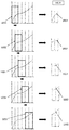
- the principle of splitting the digitized signal 1020 into sub-signals 1022 with an overlap of half is shown in figure 3 . We take a window 1021 having a size along the x-axis of twice the number of points N necessary for the calculation of the FFT.
- the window is placed at the start of the digitized signal 1020 and the digitized signal 1020 contained in the window 1021 is extracted to produce a sub-signal 1022.
- the window 1021 is then dragged by half the size of the window 1021 along the axis. abscissa and the digitized signal 1020 contained in the window 1021 is extracted in order to produce another sub-signal 1022.
- the procedure begins again until the end of the digitized signal 1020.
- sub-signals 1022 of the signal digitized 1020 we have sub-signals 1022 of the signal digitized 1020 to which we will apply the FFT.
- spectral leakage phenomenon is meant a dispersion of the power of a signal over several frequencies adjacent to the signal frequency and which therefore distorts the frequency analysis.
- Each sub-signal 1022 will give rise to a spectrum 1030 which is calculated discretely by the FFT, that is to say that for each point of the discrete sub-signal 1022, a point of the spectrum 1030 is calculated. As illustrated. to the figure 4 , the points of the spectrum are numbered with integers and these integers are called bins 1031.
- a spectrum of the sub-signal 1022 comprising N bins 1031 is thus obtained. This operation is carried out for each sub-signal 1022 of the digitized signal 1020 then for each digitized signal 1020 of each antenna 203.
- the device 200 comprises A antennas 203 , we obtain A xi spectra 1030 and A xix N bins 1031.
- a spectrogram indicates for each bin 1031 and each spectrum 1030 the amplitude and the phase of the acquisition signal 1010, delimiting time-frequency boxes. These amplitudes and these phases are a function of the position and orientation of the antennas 203 with respect to the transmitters 300.
- the frequency resolution 1032 makes it possible to define the size in frequency of the time-frequency bins of the spectrogram.
- V T denoting the conjugate transpose of V
- m the number of the sub-signal 1022
- k the number of the bin 1031.
- Each bin 1031 thus obtains a covariance matrix 1040 associated with it.
- Each covariance matrix 1040 translates the relative differences in amplitude and in phase between the different spectra 1030 contained in the vector V which was used to calculate it.
- the step 104 for calculating the block 1050 covariance matrices consists in grouping the covariance matrices 1040 corresponding to sub-signals 1022 belonging to the same block of duration 1051.
- a block of duration 1051 is defined as a sub-duration of the acquisition duration 1011, that is to say a duration less than the acquisition duration 1011, extracted from the acquisition duration 1011.
- a block of duration 1051 is for example a quarter of the acquisition duration 1011 .
- this sub-duration is rounded to correspond to a number integer of spectra 1030, that is to say to an integer number of sub-signals 1022.
- the number of blocks of duration 1051 is always greater than or equal to four.
- the spectra straddling two blocks of duration 1051 are not taken into account in the calculation of the block 1050 covariance matrices.
- Cov block mbloc k 1 B ⁇ m ⁇ block Cov m k
- B is for example the number of spectra 1030 per block rounded to the higher power of 2.
- the block covariance matrix 1050 is an averaged version of the covariance matrices 1040 over a block of duration 1051. It is now possible to construct a block covariance matrix spectrogram indicating the value of the block covariance matrix for each time-frequency slot. . This operation by block of duration 1051 makes it possible to improve the signal-to-noise ratio of the spectrogram of covariance matrices block 1050 compared to a spectrogram of covariance matrices 1040.
- the duration block 1051 makes it possible to define the size in time of the time cells.
- frequency of the block covariance matrix spectrogram and the frequency resolution 1032 makes it possible to define the frequency size of the time-frequency bins of the block covariance matrix spectrogram.
- the time-frequency bins of the block covariance matrix spectrogram are shown at figure 5 .
- the values of the duration block 1051 and the frequency resolution 1032 are chosen so that the transmitters occupy several time-frequency slots on the block covariance matrix spectrogram.
- the principle of detection used in the method 100 exploits the fact that the signals generated by the transmitters 300 have a spatial coherence greater than that of the ambient noise, that is to say that the stability between two block covariance matrices neighbors associated with an emitter signal 300 are more stable with each other than two neighboring block covariance matrices associated with noise. It is therefore no longer possible to distinguish a transmitter from ambient noise if it occupies a single time-frequency slot.
- the more the size of the time-frequency boxes increases the more the noise becomes spatially coherent because it is averaged over the time-frequency box, and the more difficult it is to detect the transmitters 300. It is therefore necessary to choose the size of the time-boxes. frequency so that the block 1050 covariance matrices of the time-frequency bins associated with the noise are considered non-collinear.
- the efficiency of the method 100 is maximum when the speed of the emitters is less than 50 km / h.
- the stability reflects the percentage of collinearity between neighboring 1050 block covariance matrices.
- a first collinearity measurement 1061 is calculated between two block 1050 covariance matrices having two neighboring blocks of duration 1051 on the block 1050 covariance matrix spectrogram and a second collinearity measurement 1062 between two block 1050 covariance matrices having two neighboring bins 1031 within the same block of duration 1051 on the block 1050 covariance matrix spectrogram.
- the first collinearity measurement 1061 makes it possible to quantify the collinearity of the block covariance matrices along the axis temporal and the second collinearity measurement 1062 makes it possible to quantify the collinearity of the block covariance matrices along the frequency axis.
- Cov block mbloc + 1 , k ⁇ ⁇ Cov block mbloc k ⁇ ⁇ Cov block mbloc + 1 , k ⁇ measured 2 mbloc k ⁇ Cov block mbloc k
- the values of the first 1061 and second collinearity measure 1062 are between 0 and 1: if the block 1050 covariance matrices are orthogonal, the first 1061 and the second 1062 collinearity measure are equal to 0 and if the block 1050 covariance matrices are collinear, the first 1061 and second collinearity measure 1062 are equal to 1.
- a collinearity product 1063 is produced between the first 1061 and second 1062 collinearity measurements during the detection step 106 for each bin 1031.
- a detection threshold 1064 is chosen. This depends on the product between the frequency resolution 1032 and the duration block 1051. In fact, the larger this product, the larger the time-frequency bins and therefore the more difficult it becomes to distinguish the emitters from the ambient noise: it It is therefore necessary to have a higher detection threshold value 1064 for protect against false alarms or detections triggered when there is no transmitter.
- the detection threshold 1064 is also chosen to guard against false detections triggered by the acquisition signals 1010 but which must not be taken into account.
- the detection threshold 1064 can for example be positioned at a value greater than 0.90.
- the number of start bins 1065 of a block of duration 1051 gives the number of transmitters whose signals were picked up over the sub-duration of the acquisition duration 1011 corresponding to the block of duration 1051. For example, if three start bins 1065 are found on the second block of duration 1051, three transmitters 300 have been detected which transmitted over the sub-duration of the acquisition duration 1011 corresponding to the second block of duration 1051.
- the transmitters 300 can be characterized to provide parameters of interest such as the center frequency, the bandwidth or even the power of the signal associated with each transmitter 300. It is also possible to locate the transmitters 300 by using for example direction finding algorithms or to follow the temporal evolution of the transmitters 300 block of duration by block of duration.
Claims (12)
- Erkennungsverfahren (100) des Vorhandenseins eines oder mehrerer funkelektrischer Sender (300) in einer Umgebung, wobei das Verfahren durch eine Vorrichtung (200) umgesetzt wird, umfassend eine Berechnungseinheit (201) und ein Antennennetz (202), umfassend eine Vielzahl von Antennen (203), die geeignet sind, simultane Erfassungen der Umgebung in Form von Erfassungssignalen (1010) während einer Erfassungsdauer (1011) zu realisieren und die Erfassungssignale (1010) simultan in digitaler Form auf die Berechnungseinheit (201) zu empfangen und zu übertragen, wobei die Berechnungseinheit (201) geeignet ist, Verarbeitungen auf digitalisierten Signalen (1020) zu realisieren, wobei das Verfahren (100) die folgenden unterschiedlichen Schritte umfasst:- Für jede Antenne (203).wobei das Verfahren (100) dadurch gekennzeichnet ist, dass es die folgenden Schritte umfasst:• Empfangen und digitalisieren des Erfassungssignals (1010) in Form eines digitalisierten Signals (1020) und übertragen des digitalisierten Signals (1020) auf die Berechnungseinheit (201) (101);• Erzeugen einer Vielzahl von Spektren (1030) ausgehend von dem digitalisierten Signal (1009) mit einer gewählten Frequenzauflösung (1032), einem Spektrum (1020), das eine Vielzahl von Punkten umfasst, wobei jeder Punkt einer als Bin (1031) (102) bezeichneten Nummer zugeordnet ist;- Für jedes Bin (1031), zusammenfassen die Spektren (1030) der unterschiedlichen Antennen (203), die dem Bin (1031) entsprechen, und berechnen eine Kovarianzmatrix (1040) (103);- Zusammenfassen der Kovarianzmatrizes (1040), deren zugeordnete Spektren (1030) einem gleichen Dauerblock (1051) entsprechen, wobei ein Dauerblock (1051) als eine Teildauer der Erfassungsdauer (1011) definiert wird, um Block-Kovarianzmatrizes (1050) (104) zu bilden;- Berechnen einer ersten Kollinearitätsmessung (1061) der Block-Kovarianzmatrizes (1050) zwischen zwei konsekutiven Dauerblöcken (1051) und einer zweiten Kollinearitätsmessung (1062) der Block-Kovarianzmatrizes (1050) zwischen zwei konsekutiven (105) Bins (1031) eines und desselben Dauerblocks (1051);- Erkennen eines oder mehrerer funkelektrischer Sender (300) durch Realisieren der folgenden Schritte:• Für jedes Bin (1031) berechnen des Produkts zwischen der ersten (1061) und der zweiten Kollinearitätsmessung (1062) zum Bilden eines Kollinearitätsprodukts (1063);• Für jeden Dauerblock (1051):∘ Erfassen der Nummer der Anfangsbins (1065), für die das Kollinearitätsprodukt (1063) über einen Schwellenwert (1064) hinausgeht, d. h., dass der Wert des Kollinearitätsprodukts (1063) für ein Anfangsbin (1065) oberhalb des Schwellenwerts (1064) und des Wertes des Kollinearitätsprodukts (1063) für das Bin (103), das diesem Anfangsbin (1065) vorausgeht, unterhalb des Schwellenwertes (1064) ist;∘ Die Anzahl der Anfangsbins (1065) ergibt die Anzahl von funkelektrischen Sendern (300), die im Dauerblock (1051) erkannt werden.
- Erkennungsverfahren (100) gemäß Anspruch 1, dadurch gekennzeichnet, dass der Schritt (102) zum Erzeugen von Spektren (1030) die folgenden Teilschritte umfasst:- Zerschneiden des digitalisierten Signals (1020) in eine Vielzahl von Fenstern (1021) derart, dass digitalisierte Teilsignale (1022) gebildet werden;- Für jedes digitalisierte Teilsignal (1022), berechnen einer diskreten Fourier-Transformierten zum erhalten eines Spektrums (1030).
- Erkennungsverfahren (100) gemäß Anspruch 2, dadurch gekennzeichnet, dass der Schritt (102) zum Erzeugen von Spektren (1030) einen Teilschritt der Vorverarbeitung zum Formatieren des digitalisierten Signals (1020) vor dem Teilschritt des Zerschneidens umfasst.
- Erkennungsverfahren (100) gemäß irgendeinem der Ansprüche 2 oder 3, dadurch gekennzeichnet, dass jedes Fenster (1021) einen Teil des vorherigen Fensters (1021) abdeckt.
- Erkennungsverfahren (100) gemäß irgendeinem der Ansprüche 2 bis 4, dadurch gekennzeichnet, dass der Schritt (102) zum erzeugen von Spektren (1030) einen Gewichtungs-Teilschritt der digitalisierten Teilsignale (1022) vor der Berechnung der diskreten Fourier-Transformierten jedes digitalisierten Teilsignals (1022) umfasst.
- Erkennungsverfahren (100) gemäß irgendeinem der voranstehenden Ansprüche, dadurch gekennzeichnet, dass die Block-Kovarianzmatrizes (1050) per Mittelung der Werte der Kovarianzmatrizes (1040) gebildet werden, die einem und demselben Dauerblock (1051) entsprechen.
- Erkennungsverfahren (100) gemäß irgendeinem der voranstehenden Ansprüche, dadurch gekennzeichnet, dass die erste Kollinearitätsmessung (1061) eine Messung des normalisierten Skalarprodukts zwischen der Block-Kovarianzmatrix (1050) eines ersten Dauerblocks (1051) und der Block-Kovarianzmatrix (1050) eines zweiten Dauerblocks (1051) ist, wobei der zweite Dauerblock (1051) der Dauerblock (1051) ist, der auf den ersten Dauerblock (1051) folgt.
- Erkennungsverfahren (100) gemäß irgendeinem der voranstehenden Ansprüche, dadurch gekennzeichnet, dass die zweite Kollinearitätsmessung (1062) eine Messung des normalisierten Skalarprodukts zwischen der Block-Kovarianzmatrix (1050) eines ersten Bins (1031) und der Block-Kovarianzmatrix (1050) eines zweiten Bins (1031) ist, wobei das zweite Bin (1031) das Bin (1031) ist, das auf das erste Bin (1031) folgt.
- Erkennungsverfahren (100) gemäß irgendeinem der voranstehenden Ansprüche, dadurch gekennzeichnet, dass der gewählte Schwellenwert (1064) von der gewählten Frequenzauflösung (1032) und der Erfassungs-Teildauer, die einem Dauerblock (1051) entspricht, abhängt.
- Vorrichtung (200), die zum umsetzen des Verfahrens gemäß irgendeinem der voranstehenden Ansprüche geeignet ist, dadurch gekennzeichnet, dass es umfasst:- Ein Antennennetz (202), umfassend eine Vielzahl von Antennen (203), die geeignet sind, Erfassungssignale (1010) gleichzeitig zu empfangen und zu digitalisieren, um sie in Form von digitalisierten Signalen (1020) auf eine Berechnungseinheit (201) zu übertragen;- Eine Berechnungseinheit (201), die geeignet ist, Berechnungs- und Erkennungsfunktionen auf digitalisierten Signalen (1020) zu realisieren.
- Computerprogramm-Produkt, umfassend Anweisungen, die, wenn das Programm von einem Computer ausgeführt wird, diesen dazu veranlassen, das Verfahren (100) gemäß irgendeinem der Ansprüche 1 bis 9 umzusetzen.
- Per Computer lesbarer Aufzeichnungsträger, umfassend Anweisungen, die, wenn sie von einem Computer ausgeführt werden, diesen dazu veranlassen, das Verfahren (100) gemäß irgendeinem der Ansprüche 1 bis 9 auszuführen.
Applications Claiming Priority (1)
| Application Number | Priority Date | Filing Date | Title |
|---|---|---|---|
| FR1701385A FR3076133B1 (fr) | 2017-12-27 | 2017-12-27 | Procede de detection d'emetteurs radioelectriques et dispositif associe |
Publications (2)
| Publication Number | Publication Date |
|---|---|
| EP3506578A1 EP3506578A1 (de) | 2019-07-03 |
| EP3506578B1 true EP3506578B1 (de) | 2020-10-21 |
Family
ID=62597541
Family Applications (1)
| Application Number | Title | Priority Date | Filing Date |
|---|---|---|---|
| EP18214722.3A Active EP3506578B1 (de) | 2017-12-27 | 2018-12-20 | Verfahren zur detektion von funksignalsendern, und entsprechende vorrichtung |
Country Status (4)
| Country | Link |
|---|---|
| US (1) | US10454742B2 (de) |
| EP (1) | EP3506578B1 (de) |
| FR (1) | FR3076133B1 (de) |
| IL (1) | IL264308A (de) |
Family Cites Families (3)
| Publication number | Priority date | Publication date | Assignee | Title |
|---|---|---|---|---|
| US8285221B2 (en) * | 2009-08-31 | 2012-10-09 | Motorola Mobility Llc | Scalable self-calibrating and configuring radio frequency head for a wireless communication system |
| FR3009912B1 (fr) * | 2013-08-23 | 2015-08-28 | Thales Sa | Procede de detection d'un signal electromagnetique par un reseau antennaire et dispositif mettant en oeuvre un procede |
| US9245433B1 (en) * | 2013-12-20 | 2016-01-26 | Amazon Technologies, Inc. | Passive device monitoring using radio frequency signals |
-
2017
- 2017-12-27 FR FR1701385A patent/FR3076133B1/fr active Active
-
2018
- 2018-12-20 EP EP18214722.3A patent/EP3506578B1/de active Active
- 2018-12-21 US US16/229,849 patent/US10454742B2/en active Active
-
2019
- 2019-01-17 IL IL264308A patent/IL264308A/en unknown
Non-Patent Citations (1)
| Title |
|---|
| None * |
Also Published As
| Publication number | Publication date |
|---|---|
| US10454742B2 (en) | 2019-10-22 |
| US20190199568A1 (en) | 2019-06-27 |
| EP3506578A1 (de) | 2019-07-03 |
| FR3076133A1 (fr) | 2019-06-28 |
| IL264308A (en) | 2019-05-30 |
| FR3076133B1 (fr) | 2019-12-27 |
Similar Documents
| Publication | Publication Date | Title |
|---|---|---|
| EP0681190B1 (de) | System und Verfahren zur diskreten Radarerkennung | |
| EP0322005B1 (de) | Radioelektrischer Sensor zur Erstellung einer radioelektrischen Karte einer Landschaft | |
| EP2344902B1 (de) | Verfahren zur bestimmung der ankunftsrichtung im hinblick auf lage einer hochfrequenten elektromagnetischen welle | |
| EP3049822B1 (de) | Verfahren zur nichtüberwachten entschachtelung durch n-dimensionale anreicherung | |
| EP3394630B1 (de) | Verfahren zur bestimmung der ankunftsrichtung in gegenwart von aliasing und zugehörige vorrichtung | |
| EP3506578B1 (de) | Verfahren zur detektion von funksignalsendern, und entsprechende vorrichtung | |
| EP3672088B1 (de) | Bipolarisiertes digitales interferometer mit unterabtastung | |
| EP2544020B1 (de) | Verfahren und Vorrichtung zur Detektion eines Ziels, das von starken Energiereflektoren maskiert wird | |
| WO2005124386A1 (fr) | Procede de detection et visualisation de sources acoustiques de faible puissance en mouvement | |
| EP3420642B1 (de) | Eingebauter sensor zum abfangen von radioelektrischen com/rad-emissionen | |
| EP4009068B1 (de) | System und verfahren zum abfangen von nicht-diskursiven elektromagnetischen signalen, die in einem breiten frequenzbereich übertragen werden | |
| EP1018654A2 (de) | Entdeckungsverfahren, insbesondere für kleine Wasserziele | |
| EP3948337B1 (de) | Verfahren und vorrichtung zur berechnung von sichtbarkeitsfunktionen für ein interferometrisches radiometer mit synthetischer apertur | |
| US9429644B1 (en) | Subaperture clutter filter with CFAR signal detection | |
| US9857453B1 (en) | High-frequency indicator phase system and method | |
| EP2662701A1 (de) | Sequenzierungsverfahren eines Empfängers | |
| FR2997252A1 (fr) | Procede et systeme de detection de signaux de diffusion emis par des sources terrestres et recus par un satellite | |
| EP3674717B1 (de) | Vorrichtung zur bestimmung des spektrums eines signals über eine grosse frequenzbandbreite durch mehrfachabtastung, und entsprechendes verfahren | |
| FR2949882A1 (fr) | Methode de traitement du signal comportant une etape d'estimation de la matrice mediane d'un echantillon de matrices | |
| EP3470871B1 (de) | Radarsignal-detektionsverfahren | |
| FR3018915A1 (fr) | Procede de detection d'un signal cible dans un signal de mesure d'un instrument embarque dans un engin spatial et systeme de mesure | |
| EP2504715B1 (de) | Mehrkanaliges empfangssystem | |
| EP3213112A1 (de) | Verfahren zur verarbeitung eines radarsignals in einem land/see-detektionsmodus, verarbeitungssystem und zugehöriges computerprogrammprodukt | |
| FR2769373A1 (fr) | Procede de detection doppler de cibles a vitesse radiale faible ou nulle | |
| FR2892831A1 (fr) | "systeme de radar a onde continue modulee en frequence et son application a la detection d'objets". |
Legal Events
| Date | Code | Title | Description |
|---|---|---|---|
| PUAI | Public reference made under article 153(3) epc to a published international application that has entered the european phase |
Free format text: ORIGINAL CODE: 0009012 |
|
| STAA | Information on the status of an ep patent application or granted ep patent |
Free format text: STATUS: THE APPLICATION HAS BEEN PUBLISHED |
|
| AK | Designated contracting states |
Kind code of ref document: A1 Designated state(s): AL AT BE BG CH CY CZ DE DK EE ES FI FR GB GR HR HU IE IS IT LI LT LU LV MC MK MT NL NO PL PT RO RS SE SI SK SM TR |
|
| AX | Request for extension of the european patent |
Extension state: BA ME |
|
| STAA | Information on the status of an ep patent application or granted ep patent |
Free format text: STATUS: REQUEST FOR EXAMINATION WAS MADE |
|
| 17P | Request for examination filed |
Effective date: 20200102 |
|
| RBV | Designated contracting states (corrected) |
Designated state(s): AL AT BE BG CH CY CZ DE DK EE ES FI FR GB GR HR HU IE IS IT LI LT LU LV MC MK MT NL NO PL PT RO RS SE SI SK SM TR |
|
| GRAP | Despatch of communication of intention to grant a patent |
Free format text: ORIGINAL CODE: EPIDOSNIGR1 |
|
| STAA | Information on the status of an ep patent application or granted ep patent |
Free format text: STATUS: GRANT OF PATENT IS INTENDED |
|
| INTG | Intention to grant announced |
Effective date: 20200529 |
|
| RAP1 | Party data changed (applicant data changed or rights of an application transferred) |
Owner name: AVANTIX |
|
| GRAS | Grant fee paid |
Free format text: ORIGINAL CODE: EPIDOSNIGR3 |
|
| GRAA | (expected) grant |
Free format text: ORIGINAL CODE: 0009210 |
|
| STAA | Information on the status of an ep patent application or granted ep patent |
Free format text: STATUS: THE PATENT HAS BEEN GRANTED |
|
| AK | Designated contracting states |
Kind code of ref document: B1 Designated state(s): AL AT BE BG CH CY CZ DE DK EE ES FI FR GB GR HR HU IE IS IT LI LT LU LV MC MK MT NL NO PL PT RO RS SE SI SK SM TR |
|
| REG | Reference to a national code |
Ref country code: GB Ref legal event code: FG4D Free format text: NOT ENGLISH |
|
| REG | Reference to a national code |
Ref country code: CH Ref legal event code: EP |
|
| REG | Reference to a national code |
Ref country code: IE Ref legal event code: FG4D Free format text: LANGUAGE OF EP DOCUMENT: FRENCH |
|
| REG | Reference to a national code |
Ref country code: DE Ref legal event code: R096 Ref document number: 602018008933 Country of ref document: DE |
|
| REG | Reference to a national code |
Ref country code: AT Ref legal event code: REF Ref document number: 1326974 Country of ref document: AT Kind code of ref document: T Effective date: 20201115 |
|
| REG | Reference to a national code |
Ref country code: AT Ref legal event code: MK05 Ref document number: 1326974 Country of ref document: AT Kind code of ref document: T Effective date: 20201021 |
|
| REG | Reference to a national code |
Ref country code: NL Ref legal event code: MP Effective date: 20201021 |
|
| PG25 | Lapsed in a contracting state [announced via postgrant information from national office to epo] |
Ref country code: GR Free format text: LAPSE BECAUSE OF FAILURE TO SUBMIT A TRANSLATION OF THE DESCRIPTION OR TO PAY THE FEE WITHIN THE PRESCRIBED TIME-LIMIT Effective date: 20210122 Ref country code: NO Free format text: LAPSE BECAUSE OF FAILURE TO SUBMIT A TRANSLATION OF THE DESCRIPTION OR TO PAY THE FEE WITHIN THE PRESCRIBED TIME-LIMIT Effective date: 20210121 Ref country code: PT Free format text: LAPSE BECAUSE OF FAILURE TO SUBMIT A TRANSLATION OF THE DESCRIPTION OR TO PAY THE FEE WITHIN THE PRESCRIBED TIME-LIMIT Effective date: 20210222 Ref country code: RS Free format text: LAPSE BECAUSE OF FAILURE TO SUBMIT A TRANSLATION OF THE DESCRIPTION OR TO PAY THE FEE WITHIN THE PRESCRIBED TIME-LIMIT Effective date: 20201021 Ref country code: FI Free format text: LAPSE BECAUSE OF FAILURE TO SUBMIT A TRANSLATION OF THE DESCRIPTION OR TO PAY THE FEE WITHIN THE PRESCRIBED TIME-LIMIT Effective date: 20201021 |
|
| REG | Reference to a national code |
Ref country code: LT Ref legal event code: MG4D |
|
| PG25 | Lapsed in a contracting state [announced via postgrant information from national office to epo] |
Ref country code: SE Free format text: LAPSE BECAUSE OF FAILURE TO SUBMIT A TRANSLATION OF THE DESCRIPTION OR TO PAY THE FEE WITHIN THE PRESCRIBED TIME-LIMIT Effective date: 20201021 Ref country code: LV Free format text: LAPSE BECAUSE OF FAILURE TO SUBMIT A TRANSLATION OF THE DESCRIPTION OR TO PAY THE FEE WITHIN THE PRESCRIBED TIME-LIMIT Effective date: 20201021 Ref country code: PL Free format text: LAPSE BECAUSE OF FAILURE TO SUBMIT A TRANSLATION OF THE DESCRIPTION OR TO PAY THE FEE WITHIN THE PRESCRIBED TIME-LIMIT Effective date: 20201021 Ref country code: IS Free format text: LAPSE BECAUSE OF FAILURE TO SUBMIT A TRANSLATION OF THE DESCRIPTION OR TO PAY THE FEE WITHIN THE PRESCRIBED TIME-LIMIT Effective date: 20210221 Ref country code: BG Free format text: LAPSE BECAUSE OF FAILURE TO SUBMIT A TRANSLATION OF THE DESCRIPTION OR TO PAY THE FEE WITHIN THE PRESCRIBED TIME-LIMIT Effective date: 20210121 Ref country code: ES Free format text: LAPSE BECAUSE OF FAILURE TO SUBMIT A TRANSLATION OF THE DESCRIPTION OR TO PAY THE FEE WITHIN THE PRESCRIBED TIME-LIMIT Effective date: 20201021 Ref country code: AT Free format text: LAPSE BECAUSE OF FAILURE TO SUBMIT A TRANSLATION OF THE DESCRIPTION OR TO PAY THE FEE WITHIN THE PRESCRIBED TIME-LIMIT Effective date: 20201021 |
|
| PG25 | Lapsed in a contracting state [announced via postgrant information from national office to epo] |
Ref country code: NL Free format text: LAPSE BECAUSE OF FAILURE TO SUBMIT A TRANSLATION OF THE DESCRIPTION OR TO PAY THE FEE WITHIN THE PRESCRIBED TIME-LIMIT Effective date: 20201021 Ref country code: HR Free format text: LAPSE BECAUSE OF FAILURE TO SUBMIT A TRANSLATION OF THE DESCRIPTION OR TO PAY THE FEE WITHIN THE PRESCRIBED TIME-LIMIT Effective date: 20201021 |
|
| REG | Reference to a national code |
Ref country code: DE Ref legal event code: R097 Ref document number: 602018008933 Country of ref document: DE |
|
| PG25 | Lapsed in a contracting state [announced via postgrant information from national office to epo] |
Ref country code: RO Free format text: LAPSE BECAUSE OF FAILURE TO SUBMIT A TRANSLATION OF THE DESCRIPTION OR TO PAY THE FEE WITHIN THE PRESCRIBED TIME-LIMIT Effective date: 20201021 Ref country code: LT Free format text: LAPSE BECAUSE OF FAILURE TO SUBMIT A TRANSLATION OF THE DESCRIPTION OR TO PAY THE FEE WITHIN THE PRESCRIBED TIME-LIMIT Effective date: 20201021 Ref country code: SK Free format text: LAPSE BECAUSE OF FAILURE TO SUBMIT A TRANSLATION OF THE DESCRIPTION OR TO PAY THE FEE WITHIN THE PRESCRIBED TIME-LIMIT Effective date: 20201021 Ref country code: SM Free format text: LAPSE BECAUSE OF FAILURE TO SUBMIT A TRANSLATION OF THE DESCRIPTION OR TO PAY THE FEE WITHIN THE PRESCRIBED TIME-LIMIT Effective date: 20201021 Ref country code: CZ Free format text: LAPSE BECAUSE OF FAILURE TO SUBMIT A TRANSLATION OF THE DESCRIPTION OR TO PAY THE FEE WITHIN THE PRESCRIBED TIME-LIMIT Effective date: 20201021 Ref country code: EE Free format text: LAPSE BECAUSE OF FAILURE TO SUBMIT A TRANSLATION OF THE DESCRIPTION OR TO PAY THE FEE WITHIN THE PRESCRIBED TIME-LIMIT Effective date: 20201021 |
|
| PLBE | No opposition filed within time limit |
Free format text: ORIGINAL CODE: 0009261 |
|
| STAA | Information on the status of an ep patent application or granted ep patent |
Free format text: STATUS: NO OPPOSITION FILED WITHIN TIME LIMIT |
|
| PG25 | Lapsed in a contracting state [announced via postgrant information from national office to epo] |
Ref country code: MC Free format text: LAPSE BECAUSE OF FAILURE TO SUBMIT A TRANSLATION OF THE DESCRIPTION OR TO PAY THE FEE WITHIN THE PRESCRIBED TIME-LIMIT Effective date: 20201021 Ref country code: DK Free format text: LAPSE BECAUSE OF FAILURE TO SUBMIT A TRANSLATION OF THE DESCRIPTION OR TO PAY THE FEE WITHIN THE PRESCRIBED TIME-LIMIT Effective date: 20201021 |
|
| REG | Reference to a national code |
Ref country code: BE Ref legal event code: MM Effective date: 20201231 |
|
| 26N | No opposition filed |
Effective date: 20210722 |
|
| PG25 | Lapsed in a contracting state [announced via postgrant information from national office to epo] |
Ref country code: IE Free format text: LAPSE BECAUSE OF NON-PAYMENT OF DUE FEES Effective date: 20201220 Ref country code: LU Free format text: LAPSE BECAUSE OF NON-PAYMENT OF DUE FEES Effective date: 20201220 Ref country code: IT Free format text: LAPSE BECAUSE OF FAILURE TO SUBMIT A TRANSLATION OF THE DESCRIPTION OR TO PAY THE FEE WITHIN THE PRESCRIBED TIME-LIMIT Effective date: 20201021 Ref country code: AL Free format text: LAPSE BECAUSE OF FAILURE TO SUBMIT A TRANSLATION OF THE DESCRIPTION OR TO PAY THE FEE WITHIN THE PRESCRIBED TIME-LIMIT Effective date: 20201021 |
|
| PG25 | Lapsed in a contracting state [announced via postgrant information from national office to epo] |
Ref country code: SI Free format text: LAPSE BECAUSE OF FAILURE TO SUBMIT A TRANSLATION OF THE DESCRIPTION OR TO PAY THE FEE WITHIN THE PRESCRIBED TIME-LIMIT Effective date: 20201021 |
|
| PG25 | Lapsed in a contracting state [announced via postgrant information from national office to epo] |
Ref country code: IS Free format text: LAPSE BECAUSE OF FAILURE TO SUBMIT A TRANSLATION OF THE DESCRIPTION OR TO PAY THE FEE WITHIN THE PRESCRIBED TIME-LIMIT Effective date: 20210221 Ref country code: TR Free format text: LAPSE BECAUSE OF FAILURE TO SUBMIT A TRANSLATION OF THE DESCRIPTION OR TO PAY THE FEE WITHIN THE PRESCRIBED TIME-LIMIT Effective date: 20201021 Ref country code: MT Free format text: LAPSE BECAUSE OF FAILURE TO SUBMIT A TRANSLATION OF THE DESCRIPTION OR TO PAY THE FEE WITHIN THE PRESCRIBED TIME-LIMIT Effective date: 20201021 Ref country code: CY Free format text: LAPSE BECAUSE OF FAILURE TO SUBMIT A TRANSLATION OF THE DESCRIPTION OR TO PAY THE FEE WITHIN THE PRESCRIBED TIME-LIMIT Effective date: 20201021 |
|
| PG25 | Lapsed in a contracting state [announced via postgrant information from national office to epo] |
Ref country code: MK Free format text: LAPSE BECAUSE OF FAILURE TO SUBMIT A TRANSLATION OF THE DESCRIPTION OR TO PAY THE FEE WITHIN THE PRESCRIBED TIME-LIMIT Effective date: 20201021 |
|
| PG25 | Lapsed in a contracting state [announced via postgrant information from national office to epo] |
Ref country code: BE Free format text: LAPSE BECAUSE OF NON-PAYMENT OF DUE FEES Effective date: 20201231 |
|
| REG | Reference to a national code |
Ref country code: CH Ref legal event code: PL |
|
| PG25 | Lapsed in a contracting state [announced via postgrant information from national office to epo] |
Ref country code: LI Free format text: LAPSE BECAUSE OF NON-PAYMENT OF DUE FEES Effective date: 20211231 Ref country code: CH Free format text: LAPSE BECAUSE OF NON-PAYMENT OF DUE FEES Effective date: 20211231 |
|
| P01 | Opt-out of the competence of the unified patent court (upc) registered |
Effective date: 20230330 |
|
| PGFP | Annual fee paid to national office [announced via postgrant information from national office to epo] |
Ref country code: GB Payment date: 20231220 Year of fee payment: 6 |
|
| PGFP | Annual fee paid to national office [announced via postgrant information from national office to epo] |
Ref country code: FR Payment date: 20231219 Year of fee payment: 6 Ref country code: DE Payment date: 20231214 Year of fee payment: 6 |