EP3506464A1 - Shaft sealing device and electric rotary machine - Google Patents
Shaft sealing device and electric rotary machine Download PDFInfo
- Publication number
- EP3506464A1 EP3506464A1 EP18213450.2A EP18213450A EP3506464A1 EP 3506464 A1 EP3506464 A1 EP 3506464A1 EP 18213450 A EP18213450 A EP 18213450A EP 3506464 A1 EP3506464 A1 EP 3506464A1
- Authority
- EP
- European Patent Office
- Prior art keywords
- machine
- seal ring
- ring member
- exterior
- peripheral surface
- Prior art date
- Legal status (The legal status is an assumption and is not a legal conclusion. Google has not performed a legal analysis and makes no representation as to the accuracy of the status listed.)
- Granted
Links
Images





Classifications
-
- F—MECHANICAL ENGINEERING; LIGHTING; HEATING; WEAPONS; BLASTING
- F16—ENGINEERING ELEMENTS AND UNITS; GENERAL MEASURES FOR PRODUCING AND MAINTAINING EFFECTIVE FUNCTIONING OF MACHINES OR INSTALLATIONS; THERMAL INSULATION IN GENERAL
- F16J—PISTONS; CYLINDERS; SEALINGS
- F16J15/00—Sealings
- F16J15/16—Sealings between relatively-moving surfaces
- F16J15/162—Special parts or details relating to lubrication or cooling of the sealing itself
-
- F—MECHANICAL ENGINEERING; LIGHTING; HEATING; WEAPONS; BLASTING
- F16—ENGINEERING ELEMENTS AND UNITS; GENERAL MEASURES FOR PRODUCING AND MAINTAINING EFFECTIVE FUNCTIONING OF MACHINES OR INSTALLATIONS; THERMAL INSULATION IN GENERAL
- F16J—PISTONS; CYLINDERS; SEALINGS
- F16J15/00—Sealings
- F16J15/16—Sealings between relatively-moving surfaces
- F16J15/40—Sealings between relatively-moving surfaces by means of fluid
-
- F—MECHANICAL ENGINEERING; LIGHTING; HEATING; WEAPONS; BLASTING
- F16—ENGINEERING ELEMENTS AND UNITS; GENERAL MEASURES FOR PRODUCING AND MAINTAINING EFFECTIVE FUNCTIONING OF MACHINES OR INSTALLATIONS; THERMAL INSULATION IN GENERAL
- F16J—PISTONS; CYLINDERS; SEALINGS
- F16J15/00—Sealings
- F16J15/16—Sealings between relatively-moving surfaces
- F16J15/32—Sealings between relatively-moving surfaces with elastic sealings, e.g. O-rings
-
- F—MECHANICAL ENGINEERING; LIGHTING; HEATING; WEAPONS; BLASTING
- F16—ENGINEERING ELEMENTS AND UNITS; GENERAL MEASURES FOR PRODUCING AND MAINTAINING EFFECTIVE FUNCTIONING OF MACHINES OR INSTALLATIONS; THERMAL INSULATION IN GENERAL
- F16J—PISTONS; CYLINDERS; SEALINGS
- F16J15/00—Sealings
- F16J15/44—Free-space packings
- F16J15/441—Free-space packings with floating ring
-
- H—ELECTRICITY
- H02—GENERATION; CONVERSION OR DISTRIBUTION OF ELECTRIC POWER
- H02K—DYNAMO-ELECTRIC MACHINES
- H02K5/00—Casings; Enclosures; Supports
- H02K5/04—Casings or enclosures characterised by the shape, form or construction thereof
- H02K5/12—Casings or enclosures characterised by the shape, form or construction thereof specially adapted for operating in liquid or gas
- H02K5/124—Sealing of shafts
-
- H—ELECTRICITY
- H02—GENERATION; CONVERSION OR DISTRIBUTION OF ELECTRIC POWER
- H02K—DYNAMO-ELECTRIC MACHINES
- H02K5/00—Casings; Enclosures; Supports
- H02K5/04—Casings or enclosures characterised by the shape, form or construction thereof
- H02K5/15—Mounting arrangements for bearing-shields or end plates
-
- H—ELECTRICITY
- H02—GENERATION; CONVERSION OR DISTRIBUTION OF ELECTRIC POWER
- H02K—DYNAMO-ELECTRIC MACHINES
- H02K7/00—Arrangements for handling mechanical energy structurally associated with dynamo-electric machines, e.g. structural association with mechanical driving motors or auxiliary dynamo-electric machines
- H02K7/18—Structural association of electric generators with mechanical driving motors, e.g. with turbines
- H02K7/1807—Rotary generators
- H02K7/1823—Rotary generators structurally associated with turbines or similar engines
-
- H—ELECTRICITY
- H02—GENERATION; CONVERSION OR DISTRIBUTION OF ELECTRIC POWER
- H02K—DYNAMO-ELECTRIC MACHINES
- H02K9/00—Arrangements for cooling or ventilating
- H02K9/10—Arrangements for cooling or ventilating by gaseous cooling medium flowing in closed circuit, a part of which is external to the machine casing
- H02K9/12—Arrangements for cooling or ventilating by gaseous cooling medium flowing in closed circuit, a part of which is external to the machine casing wherein the cooling medium circulates freely within the casing
-
- H—ELECTRICITY
- H02—GENERATION; CONVERSION OR DISTRIBUTION OF ELECTRIC POWER
- H02K—DYNAMO-ELECTRIC MACHINES
- H02K9/00—Arrangements for cooling or ventilating
- H02K9/08—Arrangements for cooling or ventilating by gaseous cooling medium circulating wholly within the machine casing
Definitions
- Embodiments of the present invention relate to shaft sealing devices and electric rotary machines.
- Electric rotary machines include a device such as a turbine electric generator and are configured such that a rotor rotates inside a stator, for example.
- a rotor rotates inside a stator
- the interior thereof is filled with a hydrogen gas, and this filling hydrogen gas is used as a cooling gas that cools a rotor and a stator.
- a shaft sealing device is provided to prevent a cooling gas, such as a hydrogen gas, from leaking to the outside.
- the right-left direction is a horizontal direction (x) and substantially corresponds to the axial direction extending along the center axis of rotation AX of a rotor of the electric rotary machine 1.
- the up-down direction is a vertical direction (z) and substantially corresponds to a part of the radial direction perpendicular to the center axis of rotation AX.
- the electric rotary machine 1 includes a rotary shaft 4 that penetrates an electric rotary machine casing 3, and a shaft sealing device 10J provided between the electric rotary machine casing 3 and the rotary shaft 4.
- a gas chamber provided on a machine interior side IN (interior) of the electric rotary machine casing 3 is filled with a cooling gas.
- a pressure P IN on the machine interior side IN is higher than a pressure P OUT (atmospheric pressure) on a machine exterior side OT (exterior) (P IN > P OUT ).
- a stator (not illustrated) is provided inside the electric rotary machine casing 3. In the stator, a stator coil (not illustrated) is disposed on a stator core (not illustrated).
- the rotary shaft 4 has a columnar outer shape and is rotatably supported by a bearing (not illustrated) such that the axial direction of the rotary shaft 4 extending along the center axis of rotation AX coincides with the horizontal direction (x).
- the rotary shaft 4 has a rotor (not illustrated).
- a rotor coil (not illustrated) is disposed on a rotor core (iron core; not illustrated).
- the rotor is housed, for example, in the stator, and the electricity is generated, for example, as the rotor rotates along with the rotary shaft 4.
- the rotor and the stator are cooled by the cooling gas filling the machine interior side IN of the electric rotary machine casing 3.
- the rotor and the stator are cooled as the cooling gas flows through a rotor cooling channel (not illustrated) formed in the rotor and a stator cooling channel (not illustrated) formed in the stator, respectively.
- the shaft sealing device 10J is provided to seal the cooling gas inside the electric rotary machine casing 3.
- the shaft sealing device 10J is a stationary member and is disposed on the electric rotary machine casing 3.
- the shaft sealing device 10J is interposed between the rotary shaft 4 and the electric rotary machine casing 3 provided around the rotary shaft 4 to prevent the cooling gas from leaking from the machine interior side IN to the machine exterior side OT of the electric rotary machine casing 3.
- Fig. 13 is an enlarged cross-sectional view taken along a vertical plane (xz plane).
- the right-left direction (x) corresponds to the axial direction
- the up-down direction (z) corresponds to a part of the radial direction.
- the shaft sealing device 10J is of a floating type, and a seal ring 30 and a coil spring 80 are housed in a seal casing 20. Details of the components constituting the shaft sealing device 10J will be described in order.
- the seal casing 20 is an annular member and is provided around the rotary shaft 4. Specifically, the seal casing 20 is disposed to surround the rotary shaft 4 in a direction of rotation T (circumferential direction) at a position closer to the outside than an outer peripheral surface of the rotary shaft 4 in the radial direction (z). An air gap G is left between an inner peripheral surface P20 of the seal casing 20 and an outer peripheral surface P4 of the rotary shaft 4.
- a seal casing chamber 21 is formed inside the seal casing 20.
- An oil inlet 211 is formed in the seal casing 20 at a position closer to the outside than the seal casing chamber 21 in the radial direction (z).
- the oil inlet 211 communicates with the seal casing chamber 21.
- a sealing oil SO is supplied into the seal casing chamber 21 through the oil inlet 211.
- the sealing oil SO having a higher pressure than the cooling gas is supplied, details of which will be described later.
- a seal casing opening 22 is formed in the seal casing 20 at a position closer to the interior than the seal casing chamber 21 in the radial direction (z).
- the seal casing opening 22 communicates with the seal casing chamber 21.
- the width of the seal casing opening 22 in the axial direction (x) is smaller than the width of the seal casing chamber 21 in the axial direction (x).
- the seal ring 30 is an annular member and is housed in the seal casing chamber 21 of the seal casing 20 such that the seal ring surrounds the rotary shaft 4. Specifically, similar to the seal casing 20, the seal ring 30 surrounds the rotary shaft 4 in the direction of rotation T at a position closer to the outside than the outer peripheral surface of the rotary shaft 4 in the radial direction (z).
- a portion located outward in the radial direction (z) and a portion located inward in the radial direction (z) differ from each other in the width in the axial direction (x).
- the width, in the axial direction (x), of the portion located outward in the radial direction (z) is greater than the width, in the axial direction (x), of the portion located inward in the radial direction (z).
- the portion of the seal ring 30 that is located outward in the radial direction (z) is housed inside the seal casing chamber 21.
- the portion of the seal ring 30 that is located inward in the radial direction (z) penetrates the seal casing opening 22.
- the seal ring 30 includes an upper half and a lower half, and the upper half and the lower half are tightened and coupled to each other with a tightening member, such as a bolt.
- the seal ring 30 includes a machine-interior-side seal ring member 30a and a machine-exterior-side seal ring member 30b.
- the machine-interior-side seal ring member 30a is located on the machine interior side IN, which is the interior of the electric rotary machine casing 3 in the electric rotary machine 1.
- the machine-exterior-side seal ring member 30b is located closer to the machine exterior side OT, which is the exterior of the electric rotary machine casing 3, than the machine-interior-side seal ring member 30a in the axial direction (x) of the rotary shaft 4.
- the machine-interior-side seal ring member 30a and the machine-exterior-side seal ring member 30b are disposed side by side in the axial direction (x).
- a ring gap RG is left between the machine-interior-side seal ring member 30a and the machine-exterior-side seal ring member 30b.
- a seal gap SG is left between an inner peripheral surface P30a of the machine-interior-side seal ring member 30a and the outer peripheral surface P4 of the rotary shaft 4, and the seal gap SG is also left between an inner peripheral surface P30b of the machine-exterior-side seal ring member 30b and the outer peripheral surface P4 of the rotary shaft 4.
- the inner peripheral surface P30a of the machine-interior-side seal ring member 30a is a flat surface that generally follows along the outer peripheral surface P4 of the rotary shaft 4.
- the inner peripheral surface P30b of the machine-exterior-side seal ring member 30b is a flat surface that generally follows along the outer peripheral surface P4 of the rotary shaft 4.
- a portion located outward in the radial direction (z) is tapered and formed such that the width in the axial direction (x) decreases from the outer side toward the inner side in the radial direction (z).
- a portion located inward in the radial direction (z) has a constant width in the axial direction (x).
- the coil spring 80 is located around the rotary shaft 4 and housed in the seal casing chamber 21 of the seal casing 20.
- the coil spring 80 urges the seal ring 30 toward the inner peripheral side in the radial direction (z).
- the coil spring 80 is housed in the seal casing chamber 21.
- the coil spring 80 is provided in the tapered portion of the ring gap RG in the seal ring 30 that is located on an outer peripheral side in the radial direction (z).
- the coil spring 80 urges the machine-interior-side seal ring member 30a and the machine-exterior-side seal ring member 30b inward in the radial direction (z).
- the coil spring 80 urges the machine-interior-side seal ring member 30a toward the machine interior side IN in the axial direction (x) and urges the machine-exterior-side seal ring member 30b toward the machine exterior side OT in the axial direction (x).
- the coil spring 80 urges the upper half of the seal ring 30, and another coil spring 80 urges the lower half of the seal ring 30.
- the urging force of the coil spring 80 that urges the upper half of the seal ring 30 and the urging force of the coil spring 80 that urges the lower half of the seal ring 30 differ from each other.
- the urging force of the coil spring 80 that urges the lower half of the seal ring 30 is greater than the urging force of the coil spring 80 that urges the upper half of the seal ring 30.
- the sealing oil SO is supplied into the seal casing 20 from a supply source (not illustrated).
- the sealing oil SO is supplied into the seal casing chamber 21 through the oil inlet 211.
- the sealing oil SO is supplied into the seal casing 20 at a pressure higher than the pressure of the cooling gas filling the interior of the electric rotary machine casing 3.
- the pressure of the sealing oil SO is, for example, higher than the pressure of the cooling gas by approximately 0.05 MPa.
- a resultant force Fx in the axial direction (x) and a resultant force Fr in the radial direction (z) are each exerted on the seal ring 30.
- the resultant force Fx in the axial direction (x) is exerted on the machine-interior-side seal ring member 30a toward the machine interior side IN in the axial direction (x).
- the resultant force Fx in the axial direction (x) is exerted on the machine-exterior-side seal ring member 30b toward the machine exterior side OT in the axial direction (x).
- the portion of the seal ring 30 that is located inward in the radial direction (z) makes tight contact with the portion of the seal casing 20 that is located inward in the radial direction (z) and in which the seal casing opening 22 is formed.
- a side surface S30a of the machine-interior-side seal ring member 30a that is located on the machine interior side IN makes tight contact with a side surface S22a of the seal casing opening 22 that is located on the machine interior side IN.
- a side surface S30b of the machine-exterior-side seal ring member 30b that is located on the machine exterior side OT makes tight contact with a side surface S22b of the seal casing opening 22 that is located on the machine exterior side OT.
- the resultant force Fr in the radial direction (z) is exerted on the machine-interior-side seal ring member 30a and the machine-exterior-side seal ring member 30b toward the inner side in the radial direction (z).
- the seal ring 30 slides in the radial direction (z) while being in tight contact with the seal casing 20.
- the sealing oil SO flows into the ring gap RG in the seal ring 30 from the seal casing chamber 21.
- the sealing oil SO that has flowed into the ring gap RG is supplied to the seal gap SG left between the inner peripheral surface P30a of the machine-interior-side seal ring member 30a and the outer peripheral surface P4 of the rotary shaft 4 and to the seal gap SG left between the inner peripheral surface P30b of the machine-exterior-side seal ring member 30b and the outer peripheral surface P4 of the rotary shaft 4.
- an oil film of the sealing oil SO is formed in the seal gap SG.
- the shaft sealing device 10J can seal the cooling gas into the machine interior side IN so that the cooling gas does not leak from the machine interior side IN to the machine exterior side OT.
- the seal ring 30 is pressed toward the outer peripheral side by the pressure of the oil film formed in the seal gap SG.
- the seal gap SG is retained between the seal ring 30 and the rotary shaft 4.
- the seal ring 30 In the shaft sealing device 10J of a floating type, a force such as a bearing counterforce is produced due to the rotation of the rotary shaft 4, and thus the seal ring 30 may become eccentric with respect to the rotary shaft 4. In this case, the seal ring 30 moves in the radial direction (z) due to the pressure produced by the oil film formed in the seal gap SG. As a result, in the shaft sealing device 10J, the alignment is corrected automatically to achieve a coaxial state in which the center axis of rotation AX of the rotary shaft 4 coincides with the center axis of the seal ring 30.
- the machine-interior-side seal ring member 30a and the machine-exterior-side seal ring member 30b of the seal ring 30 slide in the radial direction (z) while the seal ring members 30a and 30b are in tight contact with the seal casing 20 in the axial direction (x), respectively. Therefore, friction is produced between the seal casing 20 and the seal ring 30. Consequently, the temperature rises locally therebetween, and seizure may occur. As a result, the alignment may not be corrected automatically, and the sealing of the cooling gas may become insufficient.
- Examples include providing a groove having a spiral shape or the like in an inner peripheral surface of the seal ring 30 to increase the pressure effect and forming a coating layer having a small friction coefficient on a slide surface of the seal casing 20.
- the pressure P IN on the machine interior side IN filled with the cooling gas in the electric rotary machine casing 3 of the electric rotary machine 1 is higher than the pressure P OUT (atmospheric pressure) on the machine exterior side OT located outside the electric rotary machine casing 3. Therefore, in the shaft sealing device 10J, a difference ( ⁇ Pb) between a pressure P S of the seal casing chamber 21 to which the sealing oil SO has been supplied and the pressure P OUT on the machine exterior side OT of the electric rotary machine casing 3 is greater than a difference ( ⁇ Pa) between the pressure P S of the seal casing chamber 21 and the pressure P IN on the machine interior side IN ( ⁇ Pb > ⁇ Pa).
- the sealing oil SO more easily moves to the outside through the gap between the machine-exterior-side seal ring member 30b and the rotary shaft 4 than through the gap between the machine-interior-side seal ring member 30a and the rotary shaft 4, and thus the oil film may not be formed sufficiently.
- the alignment even when the alignment is automatically corrected properly in the machine-interior-side seal ring member 30a, the alignment may not be automatically corrected properly in the machine-exterior-side seal ring member 30b.
- the following performance of the machine-exterior-side seal ring member 30b is lower than the following performance of the machine-interior-side seal ring member 30a.
- the sealing of the cooling gas may become insufficient. This issue is becoming more prominent particularly with an increase in the pressure of the cooling gas.
- an object of the present invention is provide a shaft sealing device that can effectively seal a cooling gas, and an electric rotary machine that can effectively seal the cooling gas.
- a shaft sealing device is disposed between an electric rotary machine casing and a rotary shaft penetrating the electric rotary machine casing.
- the pressure inside the electric rotary machine casing filled with a cooling gas is higher than the pressure outside the electric rotary machine casing.
- the shaft sealing device tightly seals the cooling gas inside the electric rotary machine casing.
- the shaft sealing device includes a seal casing and a seal ring.
- a seal casing chamber is formed inside the seal casing, and a sealing oil having a pressure higher than the pressure of the cooling gas is supplied into the seal casing chamber.
- the seal ring is housed in the seal casing chamber.
- the seal ring includes a machine-interior-side seal ring member and a machine-exterior-side seal ring member.
- the machine-exterior-side seal ring member is located closer to the exterior of the electric rotary machine casing than the machine-interior-side seal ring member in an axial direction of the rotary shaft.
- a ring gap is left between the machine-interior-side seal ring member and the machine-exterior-side seal ring member.
- a seal gap is left between an inner peripheral surface of the machine-interior-side seal ring member and an outer peripheral surface of the rotary shaft and between an inner peripheral surface of the machine-exterior-side seal ring member and the outer peripheral surface of the rotary shaft.
- the inner peripheral surface of the machine-interior-side seal ring member is a flat surface that generally follows along the outer peripheral surface of the rotary shaft.
- a groove extending along the direction of rotation of the rotary shaft is formed in the inner peripheral surface of the machine-exterior-side seal ring member.
- the sealing oil is supplied into the seal gap from the seal casing chamber via the ring gap.
- the sealing oil is supplied into the groove from the seal casing chamber.
- a shaft sealing device 10 according to a first embodiment will be described with reference to Fig. 1 , Fig. 2 and Fig. 3 .
- Fig. 1 illustrates a cross-sectional view of the shaft sealing device 10 taken along a vertical plane (xz plane).
- Fig. 2 illustrates an inner peripheral surface of a seal ring 30 of the shaft sealing device 10.
- the up-down direction substantially corresponds to an axial direction (x) extending along a center axis of rotation AX.
- the upper side is a machine interior side IN
- the lower side is a machine exterior side OT.
- the right-left direction substantially corresponds to a direction of rotation T.
- the left side is a forward side Fw in the direction of rotation T
- the right side is a backward side Bw.
- FIG. 3 illustrates a cross-sectional view of the shaft sealing device 10 taken along the X-X plane indicated in Fig. 2 .
- the up-down direction substantially corresponds to a radial direction (z)
- the right-left direction substantially corresponds to the direction of rotation T.
- the seal ring 30 of the shaft sealing device 10 includes a machine-interior-side seal ring member 30a and a machine-exterior-side seal ring member 30b.
- the machine-interior-side seal ring member 30a and the machine-exterior-side seal ring member 30b are disposed side by side in the axial direction (x) with a ring gap RG left between the two ring members 30a and 30b.
- an inner peripheral surface P30a of the machine-interior-side seal ring member 30a is a flat surface that generally follows along an outer peripheral surface P4 of a rotary shaft 4.
- an inner peripheral surface P30b of the machine-exterior-side seal ring member 30b is not a flat surface that generally follows along the outer peripheral surface P4 of the rotary shaft 4.
- the shaft sealing device 10 of this embodiment differs from the above-described related art in terms of a part of the configuration of the seal ring 30.
- this embodiment is similar to the above-described related art. Therefore, descriptions of matters that are duplicate of those of the above-described related art will be omitted as appropriate in this embodiment.
- a groove 40 and an introduction portion 50 are formed in the inner peripheral surface P30b of the machine-exterior-side seal ring member 30b (see Fig. 1 to Fig. 3 ).
- a plurality of grooves 40 and a plurality of introduction portions 50 are formed in the direction of rotation T.
- the groove 40 is a groove (pocket groove) formed in the inner peripheral surface P30b of the machine-exterior-side seal ring member 30b such that the groove 40 extends along the direction of rotation T.
- the groove 40 is located in the inner peripheral surface P30b of the machine-exterior-side seal ring member 30b at a position closer to the forward side Fw than the introduction portion 50 in the direction of rotation T.
- the groove 40 is located in a middle portion of the inner peripheral surface P30b of the machine-exterior-side seal ring member 30b in the axial direction (x).
- a bottom surface P40 of the groove 40 opposes the outer peripheral surface P4 of the rotary shaft 4 in the radial direction (z) with a gap left between the bottom surface P40 and the outer peripheral surface P4.
- a distance HI across the gap between the bottom surface P40 of the groove 40 and the outer peripheral surface P4 of the rotary shaft 4 is constant in the direction of rotation T.
- An end surface S40 of the groove 40 located on the forward side Fw in the direction of rotation T extends along the axial direction (x) and the radial direction (z).
- the introduction portion 50 is located closer to the backward side Bw than the groove 40 in the direction of rotation T in the inner peripheral surface P30b of the machine-exterior-side seal ring member 30b.
- the introduction portion 50 is provided to introduce, into the groove 40, a sealing oil SO supplied to a seal casing chamber 21.
- the introduction portion 50 includes an introduction groove 51 and an introduction hole 53. The sealing oil SO is introduced into the groove 40 through the introduction hole 53 and the introduction groove 51 in order.
- the introduction groove 51 is located on the backward side Bw of the groove 40 in the direction of rotation T and communicates with the groove 40. Similar to the groove 40, the introduction groove 51 is located in a middle portion of the inner peripheral surface P30b of the machine-exterior-side seal ring member 30b in the axial direction (x). The introduction groove 51 is formed to have the same width as the groove 40 in the axial direction (x).
- the introduction groove 51 includes a bottom surface P51, and the bottom surface P51 opposes the outer peripheral surface P4 of the rotary shaft 4 in the radial direction (z) with a gap left between the bottom surface P51 and the outer peripheral surface P4.
- the introduction groove 51 is formed such that a distance H2 across the gap between the bottom surface P51 of the introduction groove 51 and the outer peripheral surface P4 of the rotary shaft 4 is constant in the direction of rotation T.
- the distance H2 across the gap between the bottom surface P51 of the introduction groove 51 and the outer peripheral surface P4 of the rotary shaft 4 is greater than the distance HI across the gap between the bottom surface P40 of the groove 40 and the outer peripheral surface P4 of the rotary shaft 4.
- the introduction groove 51 is deeper than the groove 40.
- an end surface S51a upstream end surface located on the backward side Bw in the direction of rotation T extends along the axial direction (x) and the radial direction (z).
- an end surface S51b downstream end surface located on the forward side Fw in the direction of rotation T extends along the axial direction (x) and the radial direction (z).
- the introduction hole 53 penetrates the inner peripheral surface P30b of the machine-exterior-side seal ring member 30b in the radial direction (z).
- the introduction hole 53 includes an oil inlet 53A and an oil outlet 53B.
- the sealing oil SO flows into the introduction hole 53 through the oil inlet 53A, and the sealing oil SO flows out through the oil outlet 53B.
- the oil inlet 53A of the introduction hole 53 is, for example, circular and is provided in an outer peripheral surface P31b of the machine-exterior-side seal ring member 30b.
- the oil outlet 53B of the introduction hole 53 is circular, for example.
- the oil outlet 53B is formed in the inner peripheral surface P30b of the machine-exterior-side seal ring member 30b and communicates with the introduction groove 51.
- the oil outlet 53B is located on the backward side Bw of the introduction groove 51 in the direction of rotation T.
- the oil outlet 53B is formed such that an end portion of the oil outlet 53B that is located on the backward side Bw in the direction of rotation T coincides with the end surface S51a of the introduction groove 51 that is located on the backward side Bw in the direction of rotation T.
- the sealing oil SO after having been supplied into the seal casing chamber 21, flows into the ring gap RG in the seal ring 30 from the seal casing chamber 21.
- the sealing oil SO that has flowed into the ring gap RG is supplied to the seal gap SG left between an inner peripheral surface P30 of the seal ring 30 and the outer peripheral surface P4 of the rotary shaft 4.
- the sealing oil SO is supplied to the seal gap SG left between the inner peripheral surface P30a of the machine-interior-side seal ring member 30a and the outer peripheral surface P4 of the rotary shaft 4, and the sealing oil SO is also supplied to the seal gap SG left between the inner peripheral surface P30b of the machine-exterior-side seal ring member 30b and the outer peripheral surface P4 of the rotary shaft 4.
- an oil film of the sealing oil SO is formed in the seal gap SG.
- a difference ( ⁇ Pb) between a pressure of the seal casing chamber 21 to which the sealing oil SO has been supplied in the shaft sealing device 10 and the pressure on the machine exterior side OT of the electric rotary machine casing 3 is greater than a difference ( ⁇ Pa) between the pressure of the seal casing chamber 21 and the pressure on the machine interior side IN ( ⁇ Pb > ⁇ Pa). Therefore, the sealing oil SO more easily moves to the outside through the gap between the machine-exterior-side seal ring member 30b and the rotary shaft 4 than through the gap between the machine-interior-side seal ring member 30a and the rotary shaft 4. Thus, the oil film of the sealing oil SO may not be formed sufficiently. As a result, the automatic alignment correction may not take place sufficiently in the machine-exterior-side seal ring member 30b as compared to the machine-interior-side seal ring member 30a.
- the groove 40 and the introduction portion 50 are formed in the inner peripheral surface P30b of the machine-exterior-side seal ring member 30b, and the sealing oil SO is supplied into the groove 40 via the introduction portion 50. Therefore, the alignment is automatically corrected properly in the machine-exterior-side seal ring member 30b, as in the machine-interior-side seal ring member 30a.
- the sealing oil SO supplied to the seal casing chamber 21 flows into the introduction groove 51 after having passed through the introduction hole 53. Then, the sealing oil SO that has flowed into the introduction groove 51 is introduced into the groove 40. Accordingly, the sealing oil SO is further supplied to the seal gap SG between the inner peripheral surface P30b of the machine-exterior-side seal ring member 30b and the outer peripheral surface P4 of the rotary shaft 4, and thus the oil film is formed sufficiently.
- the alignment is automatically corrected properly in the machine-exterior-side seal ring member 30b, as in the machine-interior-side seal ring member 30a, and the sealing performance improves.
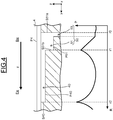
- Fig. 4 to Fig. 6 each illustrate a pressure distribution of the sealing oil SO introduced into the groove 40 and the introduction portion 50 in the machine-exterior-side seal ring member 30b.
- a cross-sectional view taken along the X-X plane indicated in Fig. 2 (similar to Fig. 3 ) is illustrated in the upper part of the drawing, and the pressure distribution of the sealing oil SO along that cross-section is illustrated in the lower part of the drawing.
- the vertical axis represents the pressure P (pressure)
- the horizontal axis represents the position in the direction of rotation T.
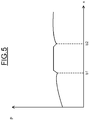
- FIG. 5 illustrates a pressure distribution at a portion r0 (the end surface S51a of the introduction groove 51 that is located on the backward side Bw in the direction of rotation T) indicated in Fig. 4 .
- the vertical axis represents the pressure P (pressure), and the horizontal axis represents the position in the axial direction (x).
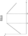
- Fig. 6 illustrates a pressure distribution at a portion r1 (the end surface S51b of the introduction groove 51 that is located on the forward side Fw in the direction of rotation T) indicated in Fig. 4 .
- the vertical axis represents the pressure P (pressure)
- the horizontal axis represents the position in the axial direction (x).
- b2 is the position of one end surface of the introduction groove 51 that is located closer to the ring gap RG
- b1 is the position of another end surface (opposite end surface) of the introduction groove 51 that is located farther from the ring gap RG.
- the sealing oil SO flows from the introduction hole 53 into the introduction groove 51 having a greater channel area than the introduction hole 53 (see Fig. 4 ).
- the introduction hole 53 is formed on the side of the end surface S51a (portion r0) of the introduction groove 51 that is located on the backward side Bw in the direction of rotation T. Therefore, the flow rate of the sealing oil SO increases on the side of the end surface S51a (portion r0), and the sealing oil SO is introduced into the introduction groove 51 without a decrease in the pressure P of the sealing oil SO.
- the pressure P of the sealing oil SO is higher inside the introduction groove 51 (the range from b1 to b2) than around the introduction groove 51 (outside the range from b1 to b2).
- the pressure P of the sealing oil SO inside the introduction groove 51 is uniformly distributed in the axial direction (x).
- the sealing oil SO flows along the direction of rotation T of the rotary shaft 4.
- the sealing oil SO flows from the end surface S51a (portion r0) located on the backward side Bw in the direction of rotation T toward the end surface S51b (portion r1) located on the forward side Fw (see Fig. 4 ).
- the pressure P of the sealing oil SO rises along the direction of rotation T.
- the pressure P of the sealing oil SO is higher inside the introduction groove 51 (the range from b1 to b2) than around the introduction groove 51 (outside the range from b1 to b2).
- the pressure P of the sealing oil SO inside the introduction groove 51 is uniformly distributed in the axial direction (x).
- the pressure P of the sealing oil SO introduced into the introduction groove 51 is higher than the pressure of an oil film formed around the introduction groove 51.
- the sealing oil SO forming the oil film around the introduction groove 51 is less likely to enter the introduction groove 51 from the machine interior side IN. Accordingly, the cooling gas filling the interior of the electric rotary machine 1 is less likely to leak through the introduction groove 51.
- the sealing oil SO supplied to the introduction groove 51 is introduced into the groove 40.
- the sealing oil SO flows along the direction of rotation T of the rotary shaft 4.
- the pressure P of the sealing oil SO decreases along the direction of rotation T.
- the sealing oil SO reaches the end surface S40 (portion r2) of the groove 40 that is located on the forward side Fw in the direction of rotation T, the kinetic energy of the sealing oil SO is converted to the pressure energy. Therefore, the pressure P of the sealing oil SO, after having decreased along the direction of rotation T, rises as the sealing oil SO approaches the end surface S40 of the groove 40 that is located on the forward side Fw in the direction of rotation T.
- the pressure of the sealing oil SO in the groove 40 is further exerted on the machine-exterior-side seal ring member 30b, and thus the machine-exterior-side seal ring member 30b is pressed further toward the outer peripheral side in the radial direction (z) than the machine-interior-side seal ring member 30a.
- the sealing oil SO is supplied into the groove 40 via the introduction portion 50.
- the alignment is automatically corrected properly in the machine-exterior-side seal ring member 30b, as in the machine-interior-side seal ring member 30a, and thus the sealing performance of the shaft sealing device 10 improves.
- the inner peripheral surface P30a of the machine-interior-side seal ring member 30a is a flat surface that generally follows along the outer peripheral surface P4 of the rotary shaft 4.
- the inner peripheral surface P30a of the machine-interior-side seal ring member 30a has neither the introduction portion 50 nor the groove 40 formed therein and is not configured such that the sealing oil SO is supplied into the groove 40 via the introduction portion 50.
- an increase in the sealing oil SO is suppressed as compared to a case in which the introduction portion 50 and the groove 40 are formed in each of the inner peripheral surface P30b of the machine-exterior-side seal ring member 30b and the inner peripheral surface P30a of the machine-interior-side seal ring member 30a, and thus the sealing oil SO can be used effectively.
- FIG. 7 shows an inner peripheral surface of a seal ring 30 of the shaft sealing device 10.
- a waste oil groove 45 is formed in the inner peripheral surface P30b of the machine-exterior-side seal ring member 30b.
- the waste oil groove 45 communicates with the groove 40 at a position on the forward side Fw in the direction of rotation T.
- the waste oil groove 45 is configured to discharge the sealing oil SO to the machine exterior side OT (exterior) of the electric rotary machine casing 3 from the groove 40.
- the waste oil groove 45 extends along the axial direction (x), and its inlet and outlet are located at the same position when viewed in the direction of rotation T.
- the pressure of the sealing oil SO in the groove 40 of the machine-exterior-side seal ring member 30b is high at the end surface S40 that is located on the forward side Fw in the direction of rotation T.
- the pressure of the sealing oil SO at the end surface S40 is higher than the pressure of the sealing oil SO in the seal casing chamber 21.
- the sealing oil SO tends to flow to not only the machine exterior side OT of the electric rotary machine casing 3 but the machine interior side IN of the electric rotary machine casing 3.
- the sealing oil OS enters the gap between the inner peripheral surface P30a of the machine-interior-side seal ring member 30a and the outer peripheral surface P4 of the rotary shaft 4 from the groove 40 of the machine-exterior-side seal ring member 30b, and an amount of the sealing oil SO increases.
- an amount of the sealing oil SO increases, an amount of the hydrogen gas, which is the cooling gas, to be absorbed by the sealing oil SO increases. Accordingly, an amount of the hydrogen gas, i.e., the cooling gas, to be consumed increases.
- the sealing oil OS exits to the machine exterior side OT (exterior) of the electric rotary machine casing 3 from the waste oil groove 45 of the groove 40 that is located on the forward side Fw in the direction of rotation T. In this embodiment, therefore, an amount of the sealing oil OS that flows to the machine interior side IN of the electric rotary machine casing 3 from the groove 40 of the machine-exterior-side seal ring member 30b decreases.
- this embodiment can demonstrate the same advantages as the first embodiment, and can also suppress the increase in the amount of consumption of the hydrogen gas, i.e., the cooling gas.
- the waste oil groove 45 extends along the axial direction (x), and its inlet and outlet are located at the same position when viewed in the direction of rotation T.
- the second embodiment is not limited to this configuration.
- FIG. 8 shows an inner peripheral surface of a seal ring 30 of the shaft sealing device 10.
- the extending direction of the waste oil groove 45 may incline relative to the direction of rotation T such that the inlet of the waste oil groove 45 is located closer to the forward side Fw than the outlet of the waste oil groove 45 when viewed in the direction of rotation T.
- the end surface S40 of the groove 40 of the machine-exterior-side seal ring member 30b that is located on the forward side Fw in the direction of rotation T may incline relative to the direction of rotation T.
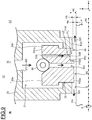
- FIG. 9 illustrates a cross-sectional view of the shaft sealing device 10 taken along a vertical plane (xz plane).
- Fig. 10 illustrates an inner peripheral surface of a seal ring 30 of the shaft sealing device 10.
- the inner peripheral surface P30b of the machine-exterior-side seal ring member 30b of the seal ring 30 of this embodiment is partially different from that of the first embodiment (see Fig. 1 and Fig. 2 ). Except for this difference and associated differences, this embodiment is similar to Embodiment 1. Thus, the duplicated description between the first embodiment and the third embodiment will be omitted as appropriate in the following passages.
- a waste oil opening 46 is formed in the inner peripheral surface P30b of the machine-exterior-side seal ring member 30b such that the waste oil opening 46 is provided in a portion closer to the machine exterior side OT than the groove 40.
- the waste oil opening 46 is formed in the ring shape along the direction of rotation T.
- the portion, which is closer to the machine exterior side OT than the groove 40, of the inner peripheral surface P30b of the machine-exterior-side seal ring member 30b is more distant from the outer peripheral surface P4 of the rotary shaft 4 than a portion, which is closer to the machine interior side IN than the groove 40, of the inner peripheral surface P30b of the machine-exterior-side seal ring member 30b.
- a distance Hb between the inner peripheral surface P30b of the machine-exterior-side seal ring member 30b that is located closer to the machine exterior side OT than the groove 40 and the outer peripheral surface P4 of the rotary shaft 4 is longer than a distance Ha between the inner peripheral surface P30b of the machine-exterior-side seal ring member 30b that is located closer to the machine interior side IN than the groove 40 and the outer peripheral surface P4 of the rotary shaft 4.
- the waste oil opening 46 is formed in the portion of the inner peripheral surface P30b of the machine-exterior-side seal ring member 30b that is closer to the machine exterior side OT than the groove 40.
- the seal gap SG between the machine-exterior-side seal ring member 30b and the rotary shaft 4 is greater in the portion, which is closer to the machine exterior side OT than the groove 40, than in the portion, which is closer to the machine interior side IN than the groove 40.
- the sealing oil SO supplied to the groove 40 of the machine-exterior-side seal ring member 30b tends to flow to the machine exterior side OT than to the machine interior side IN.
- an amount of the sealing oil SO that flows to the machine interior side IN of the electric rotary machine casing 3 from the groove 40 of the machine-exterior-side seal ring member 30b decreases.
- This embodiment therefore, can suppress the increase in the amount of consumption of the hydrogen gas, i.e., the cooling gas, as understood from the description of the second embodiment.
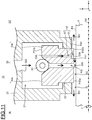
- FIG. 11 illustrates a cross-sectional view of a portion of the electric rotary machine 1, on which the shaft sealing device 10 is provided, taken along a vertical plane (xz plane).
- a protrusion 300 is formed on the outer peripheral surface P4 of the rotary shaft 4 of the electric rotary machine 1 in this embodiment. Except for this configuration and associated structures, this embodiment is similar to Embodiment 1. Thus, the duplicated description between the first embodiment and the fourth embodiment will be omitted as appropriate in the following passages.
- the protrusion 300 stands (protrudes) in the radial direction (z) of the rotary shaft 4, and has a ring shape that extends in the direction of rotation T.
- the protrusion 300 is provided on the outer peripheral surface P4 of the rotary shaft 4 at a portion closer to the machine interior side IN of the electric rotary machine casing 3 than the groove 40 of the machine-exterior-side seal ring member 30b. Specifically, the protrusion 300 is provided at the portion of the outer peripheral surface P4 of the rotary shaft 4 that faces the ring gap RG.
- This embodiment therefore, can suppress the increase in the amount of consumption of the hydrogen gas, i.e., the cooling gas, as understood from the description of the second embodiment.
Landscapes
- Engineering & Computer Science (AREA)
- General Engineering & Computer Science (AREA)
- Mechanical Engineering (AREA)
- Power Engineering (AREA)
- Motor Or Generator Cooling System (AREA)
- Mechanical Sealing (AREA)
- Motor Or Generator Frames (AREA)
- Sealing Using Fluids, Sealing Without Contact, And Removal Of Oil (AREA)
- Sealing Devices (AREA)
Abstract
Description
- Embodiments of the present invention relate to shaft sealing devices and electric rotary machines.
- Electric rotary machines include a device such as a turbine electric generator and are configured such that a rotor rotates inside a stator, for example. In an electric rotary machine, such as a turbine electric generator, the interior thereof is filled with a hydrogen gas, and this filling hydrogen gas is used as a cooling gas that cools a rotor and a stator. In an electric rotary machine, a shaft sealing device is provided to prevent a cooling gas, such as a hydrogen gas, from leaking to the outside.
- An
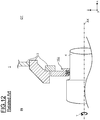
electric rotary machine 1 according to a related art will be described with reference toFig. 12 of the accompanying drawings. InFig. 12 , the right-left direction is a horizontal direction (x) and substantially corresponds to the axial direction extending along the center axis of rotation AX of a rotor of theelectric rotary machine 1. In addition, inFig. 12 , the up-down direction is a vertical direction (z) and substantially corresponds to a part of the radial direction perpendicular to the center axis of rotation AX. - As illustrated in
Fig. 12 , theelectric rotary machine 1 includes arotary shaft 4 that penetrates an electricrotary machine casing 3, and ashaft sealing device 10J provided between the electricrotary machine casing 3 and therotary shaft 4. - In the
electric rotary machine 1, a gas chamber provided on a machine interior side IN (interior) of the electricrotary machine casing 3 is filled with a cooling gas. In the electricrotary machine casing 3, a pressure PIN on the machine interior side IN is higher than a pressure POUT (atmospheric pressure) on a machine exterior side OT (exterior) (PIN > POUT). A stator (not illustrated) is provided inside the electricrotary machine casing 3. In the stator, a stator coil (not illustrated) is disposed on a stator core (not illustrated). - The
rotary shaft 4 has a columnar outer shape and is rotatably supported by a bearing (not illustrated) such that the axial direction of therotary shaft 4 extending along the center axis of rotation AX coincides with the horizontal direction (x). Therotary shaft 4 has a rotor (not illustrated). In the rotor, a rotor coil (not illustrated) is disposed on a rotor core (iron core; not illustrated). The rotor is housed, for example, in the stator, and the electricity is generated, for example, as the rotor rotates along with therotary shaft 4. Inside the electricrotary machine casing 3, the rotor and the stator are cooled by the cooling gas filling the machine interior side IN of the electricrotary machine casing 3. For example, the rotor and the stator are cooled as the cooling gas flows through a rotor cooling channel (not illustrated) formed in the rotor and a stator cooling channel (not illustrated) formed in the stator, respectively. - The
shaft sealing device 10J is provided to seal the cooling gas inside the electricrotary machine casing 3. Theshaft sealing device 10J is a stationary member and is disposed on the electricrotary machine casing 3. Theshaft sealing device 10J is interposed between therotary shaft 4 and the electricrotary machine casing 3 provided around therotary shaft 4 to prevent the cooling gas from leaking from the machine interior side IN to the machine exterior side OT of the electricrotary machine casing 3. - An example of the
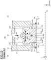
shaft sealing device 10J of theelectric rotary machine 1 according to the related art will be described with reference toFig. 13 of the accompanying drawings.Fig. 13 is an enlarged cross-sectional view taken along a vertical plane (xz plane). InFig. 13 , the right-left direction (x) corresponds to the axial direction, and the up-down direction (z) corresponds to a part of the radial direction. - As illustrated in
Fig. 13 , theshaft sealing device 10J is of a floating type, and aseal ring 30 and acoil spring 80 are housed in aseal casing 20. Details of the components constituting theshaft sealing device 10J will be described in order. - The
seal casing 20 is an annular member and is provided around therotary shaft 4. Specifically, theseal casing 20 is disposed to surround therotary shaft 4 in a direction of rotation T (circumferential direction) at a position closer to the outside than an outer peripheral surface of therotary shaft 4 in the radial direction (z). An air gap G is left between an inner peripheral surface P20 of theseal casing 20 and an outer peripheral surface P4 of therotary shaft 4. - A
seal casing chamber 21 is formed inside theseal casing 20. Anoil inlet 211 is formed in theseal casing 20 at a position closer to the outside than theseal casing chamber 21 in the radial direction (z). Theoil inlet 211 communicates with theseal casing chamber 21. In theseal casing 20, a sealing oil SO is supplied into theseal casing chamber 21 through theoil inlet 211. The sealing oil SO having a higher pressure than the cooling gas is supplied, details of which will be described later. - A
seal casing opening 22 is formed in theseal casing 20 at a position closer to the interior than theseal casing chamber 21 in the radial direction (z). The seal casing opening 22 communicates with theseal casing chamber 21. The width of the seal casing opening 22 in the axial direction (x) is smaller than the width of theseal casing chamber 21 in the axial direction (x). - The
seal ring 30 is an annular member and is housed in theseal casing chamber 21 of theseal casing 20 such that the seal ring surrounds therotary shaft 4. Specifically, similar to theseal casing 20, theseal ring 30 surrounds therotary shaft 4 in the direction of rotation T at a position closer to the outside than the outer peripheral surface of therotary shaft 4 in the radial direction (z). - In the
seal ring 30, a portion located outward in the radial direction (z) and a portion located inward in the radial direction (z) differ from each other in the width in the axial direction (x). The width, in the axial direction (x), of the portion located outward in the radial direction (z) is greater than the width, in the axial direction (x), of the portion located inward in the radial direction (z). - The portion of the
seal ring 30 that is located outward in the radial direction (z) is housed inside theseal casing chamber 21. The portion of theseal ring 30 that is located inward in the radial direction (z) penetrates the seal casing opening 22. - Although not illustrated, the
seal ring 30 includes an upper half and a lower half, and the upper half and the lower half are tightened and coupled to each other with a tightening member, such as a bolt. - The
seal ring 30 includes a machine-interior-sideseal ring member 30a and a machine-exterior-sideseal ring member 30b. The machine-interior-sideseal ring member 30a is located on the machine interior side IN, which is the interior of the electricrotary machine casing 3 in theelectric rotary machine 1. In contrast, the machine-exterior-sideseal ring member 30b is located closer to the machine exterior side OT, which is the exterior of the electricrotary machine casing 3, than the machine-interior-sideseal ring member 30a in the axial direction (x) of therotary shaft 4. The machine-interior-sideseal ring member 30a and the machine-exterior-sideseal ring member 30b are disposed side by side in the axial direction (x). A ring gap RG is left between the machine-interior-sideseal ring member 30a and the machine-exterior-sideseal ring member 30b. A seal gap SG is left between an inner peripheral surface P30a of the machine-interior-sideseal ring member 30a and the outer peripheral surface P4 of therotary shaft 4, and the seal gap SG is also left between an inner peripheral surface P30b of the machine-exterior-sideseal ring member 30b and the outer peripheral surface P4 of therotary shaft 4. - The inner peripheral surface P30a of the machine-interior-side
seal ring member 30a is a flat surface that generally follows along the outer peripheral surface P4 of therotary shaft 4. In a similar manner, the inner peripheral surface P30b of the machine-exterior-sideseal ring member 30b is a flat surface that generally follows along the outer peripheral surface P4 of therotary shaft 4. - In the ring gap RG, a portion located outward in the radial direction (z) is tapered and formed such that the width in the axial direction (x) decreases from the outer side toward the inner side in the radial direction (z). In the ring gap RG, a portion located inward in the radial direction (z) has a constant width in the axial direction (x).
- The
coil spring 80 is located around therotary shaft 4 and housed in theseal casing chamber 21 of theseal casing 20. Thecoil spring 80 urges theseal ring 30 toward the inner peripheral side in the radial direction (z). - Specifically, the
coil spring 80 is housed in theseal casing chamber 21. Thecoil spring 80 is provided in the tapered portion of the ring gap RG in theseal ring 30 that is located on an outer peripheral side in the radial direction (z). Thecoil spring 80 urges the machine-interior-sideseal ring member 30a and the machine-exterior-sideseal ring member 30b inward in the radial direction (z). In addition, thecoil spring 80 urges the machine-interior-sideseal ring member 30a toward the machine interior side IN in the axial direction (x) and urges the machine-exterior-sideseal ring member 30b toward the machine exterior side OT in the axial direction (x). - Although not illustrated, the
coil spring 80 urges the upper half of theseal ring 30, and anothercoil spring 80 urges the lower half of theseal ring 30. The urging force of thecoil spring 80 that urges the upper half of theseal ring 30 and the urging force of thecoil spring 80 that urges the lower half of theseal ring 30 differ from each other. Typically, to support theseal ring 30, the urging force of thecoil spring 80 that urges the lower half of theseal ring 30 is greater than the urging force of thecoil spring 80 that urges the upper half of theseal ring 30. - An operation of the above-described
shaft sealing device 10J will be described. - When the electric
rotary machine 1 is operated, the sealing oil SO is supplied into the seal casing 20 from a supply source (not illustrated). In theseal casing 20, the sealing oil SO is supplied into theseal casing chamber 21 through theoil inlet 211. The sealing oil SO is supplied into theseal casing 20 at a pressure higher than the pressure of the cooling gas filling the interior of the electricrotary machine casing 3. The pressure of the sealing oil SO is, for example, higher than the pressure of the cooling gas by approximately 0.05 MPa. Thus, a resultant force of the urging force of thecoil spring 80 and the pressure of the sealing oil SO is exerted on theseal ring 30 in theshaft sealing device 10J. - Specifically, a resultant force Fx in the axial direction (x) and a resultant force Fr in the radial direction (z) are each exerted on the
seal ring 30. The resultant force Fx in the axial direction (x) is exerted on the machine-interior-sideseal ring member 30a toward the machine interior side IN in the axial direction (x). In a similar manner, the resultant force Fx in the axial direction (x) is exerted on the machine-exterior-sideseal ring member 30b toward the machine exterior side OT in the axial direction (x). As a result, the portion of theseal ring 30 that is located inward in the radial direction (z) makes tight contact with the portion of theseal casing 20 that is located inward in the radial direction (z) and in which theseal casing opening 22 is formed. In other words, a side surface S30a of the machine-interior-sideseal ring member 30a that is located on the machine interior side IN makes tight contact with a side surface S22a of theseal casing opening 22 that is located on the machine interior side IN. In addition, a side surface S30b of the machine-exterior-sideseal ring member 30b that is located on the machine exterior side OT makes tight contact with a side surface S22b of theseal casing opening 22 that is located on the machine exterior side OT. - Aside from the above, the resultant force Fr in the radial direction (z) is exerted on the machine-interior-side
seal ring member 30a and the machine-exterior-sideseal ring member 30b toward the inner side in the radial direction (z). As a result, theseal ring 30 slides in the radial direction (z) while being in tight contact with theseal casing 20. - In the
shaft sealing device 10J, the sealing oil SO, after having been supplied into theseal casing chamber 21, flows into the ring gap RG in theseal ring 30 from theseal casing chamber 21. The sealing oil SO that has flowed into the ring gap RG is supplied to the seal gap SG left between the inner peripheral surface P30a of the machine-interior-sideseal ring member 30a and the outer peripheral surface P4 of therotary shaft 4 and to the seal gap SG left between the inner peripheral surface P30b of the machine-exterior-sideseal ring member 30b and the outer peripheral surface P4 of therotary shaft 4. Thus, an oil film of the sealing oil SO is formed in the seal gap SG. As a result, theshaft sealing device 10J can seal the cooling gas into the machine interior side IN so that the cooling gas does not leak from the machine interior side IN to the machine exterior side OT. Theseal ring 30 is pressed toward the outer peripheral side by the pressure of the oil film formed in the seal gap SG. Thus, the seal gap SG is retained between theseal ring 30 and therotary shaft 4. - In the
shaft sealing device 10J of a floating type, a force such as a bearing counterforce is produced due to the rotation of therotary shaft 4, and thus theseal ring 30 may become eccentric with respect to therotary shaft 4. In this case, theseal ring 30 moves in the radial direction (z) due to the pressure produced by the oil film formed in the seal gap SG. As a result, in theshaft sealing device 10J, the alignment is corrected automatically to achieve a coaxial state in which the center axis of rotation AX of therotary shaft 4 coincides with the center axis of theseal ring 30. - For example, when the
rotary shaft 4 moves upward, the pressure of the oil film rises in the seal gap SG located on an upper side of therotary shaft 4, and thus theseal ring 30 located on an upper side of therotary shaft 4 moves upward. Then, the pressure of the oil film decreases in the seal gap SG located on a lower side of therotary shaft 4, and thus theseal ring 30 located on a lower side of therotary shaft 4 moves upward due to the urging force of thecoil spring 80. In other words, when therotary shaft 4 moves, theseal ring 30 also moves to follow therotary shaft 4. Accordingly, the alignment is corrected automatically as described above. - As already described above, in the
shaft sealing device 10J of a floating type, the machine-interior-sideseal ring member 30a and the machine-exterior-sideseal ring member 30b of theseal ring 30 slide in the radial direction (z) while theseal ring members seal casing 20 in the axial direction (x), respectively. Therefore, friction is produced between theseal casing 20 and theseal ring 30. Consequently, the temperature rises locally therebetween, and seizure may occur. As a result, the alignment may not be corrected automatically, and the sealing of the cooling gas may become insufficient. - To address these issues, a variety of techniques are proposed. Examples include providing a groove having a spiral shape or the like in an inner peripheral surface of the
seal ring 30 to increase the pressure effect and forming a coating layer having a small friction coefficient on a slide surface of theseal casing 20. - However, an increase in the capacity of the electric
rotary machine 1 has led to an increase in the pressure of the cooling gas filling the machine interior side IN of the electricrotary machine casing 3. In association therewith, the pressure of the sealing oil SO supplied into theseal casing 20 is also increased. Accordingly, the pressing force with which theseal ring 30 presses theseal casing 20 is increasing, and thus the frictional force produced between theseal ring 30 and theseal casing 20 is increasing. As a result, the alignment may not be corrected automatically, and the sealing of the cooling gas may become insufficient. - As described above, the pressure PIN on the machine interior side IN filled with the cooling gas in the electric
rotary machine casing 3 of the electricrotary machine 1 is higher than the pressure POUT (atmospheric pressure) on the machine exterior side OT located outside the electricrotary machine casing 3. Therefore, in theshaft sealing device 10J, a difference (ΔPb) between a pressure PS of theseal casing chamber 21 to which the sealing oil SO has been supplied and the pressure POUT on the machine exterior side OT of the electricrotary machine casing 3 is greater than a difference (ΔPa) between the pressure PS of theseal casing chamber 21 and the pressure PIN on the machine interior side IN (ΔPb > ΔPa). Accordingly, the sealing oil SO more easily moves to the outside through the gap between the machine-exterior-sideseal ring member 30b and therotary shaft 4 than through the gap between the machine-interior-sideseal ring member 30a and therotary shaft 4, and thus the oil film may not be formed sufficiently. As a result, even when the alignment is automatically corrected properly in the machine-interior-sideseal ring member 30a, the alignment may not be automatically corrected properly in the machine-exterior-sideseal ring member 30b. In other words, the following performance of the machine-exterior-sideseal ring member 30b is lower than the following performance of the machine-interior-sideseal ring member 30a. As a result, the sealing of the cooling gas may become insufficient. This issue is becoming more prominent particularly with an increase in the pressure of the cooling gas. - Accordingly, an object of the present invention is provide a shaft sealing device that can effectively seal a cooling gas, and an electric rotary machine that can effectively seal the cooling gas.
-
-
Fig. 1 illustrates a primary portion of a shaft sealing device in an electric rotary machine according to a first embodiment of the present invention. -
Fig. 2 illustrates another primary portion of the shaft sealing device in the electric rotary machine according to the first embodiment. -
Fig. 3 illustrates still another primary portion of the shaft sealing device in the electric rotary machine according to the first embodiment. -
Fig. 4 illustrates a pressure distribution of a sealing oil introduced into a groove and an introduction portion in a seal ring of the shaft sealing device according to the first embodiment. -
Fig. 5 illustrates a particular part of the pressure distribution of the sealing oil introduced into the groove and the introduction portion in the seal ring of the shaft sealing device according to the first embodiment. -
Fig. 6 illustrates another part of the pressure distribution of the sealing oil introduced into the groove and the introduction portion in the seal ring of the shaft sealing device according to the first embodiment. -
Fig. 7 is a cross-sectional view illustrating a primary portion of a shaft sealing device in an electric rotary machine according to a second embodiment. -
Fig. 8 illustrates a primary portion of a shaft sealing device according to a modification of the second embodiment. -
Fig. 9 illustrates a primary portion of a shaft sealing device in an electric rotary machine according to a third embodiment. -
Fig. 10 illustrates another primary portion of the shaft sealing device in the electric rotary machine according to the third embodiment. -
Fig. 11 illustrates a portion in which a shaft sealing device is provided in an electric rotary machine according to a fourth embodiment. -
Fig. 12 is a fragmentary cross-sectional view illustrating a primary portion of an electric rotary machine according to a related art. -
Fig. 13 illustrates a primary portion of the shaft sealing device in the electric rotary machine according to the related art. - A shaft sealing device according to an embodiment is disposed between an electric rotary machine casing and a rotary shaft penetrating the electric rotary machine casing. The pressure inside the electric rotary machine casing filled with a cooling gas is higher than the pressure outside the electric rotary machine casing. The shaft sealing device tightly seals the cooling gas inside the electric rotary machine casing. The shaft sealing device includes a seal casing and a seal ring. A seal casing chamber is formed inside the seal casing, and a sealing oil having a pressure higher than the pressure of the cooling gas is supplied into the seal casing chamber. The seal ring is housed in the seal casing chamber. The seal ring includes a machine-interior-side seal ring member and a machine-exterior-side seal ring member. The machine-exterior-side seal ring member is located closer to the exterior of the electric rotary machine casing than the machine-interior-side seal ring member in an axial direction of the rotary shaft. A ring gap is left between the machine-interior-side seal ring member and the machine-exterior-side seal ring member. In addition, a seal gap is left between an inner peripheral surface of the machine-interior-side seal ring member and an outer peripheral surface of the rotary shaft and between an inner peripheral surface of the machine-exterior-side seal ring member and the outer peripheral surface of the rotary shaft. The inner peripheral surface of the machine-interior-side seal ring member is a flat surface that generally follows along the outer peripheral surface of the rotary shaft. A groove extending along the direction of rotation of the rotary shaft is formed in the inner peripheral surface of the machine-exterior-side seal ring member. The sealing oil is supplied into the seal gap from the seal casing chamber via the ring gap. In addition, the sealing oil is supplied into the groove from the seal casing chamber.
- A
shaft sealing device 10 according to a first embodiment will be described with reference toFig. 1 ,Fig. 2 andFig. 3 . - Similar to
Fig. 13 ,Fig. 1 illustrates a cross-sectional view of theshaft sealing device 10 taken along a vertical plane (xz plane).Fig. 2 illustrates an inner peripheral surface of aseal ring 30 of theshaft sealing device 10. InFig. 2 , the up-down direction substantially corresponds to an axial direction (x) extending along a center axis of rotation AX. The upper side is a machine interior side IN, and the lower side is a machine exterior side OT. InFig. 2 , the right-left direction substantially corresponds to a direction of rotation T. The left side is a forward side Fw in the direction of rotation T, and the right side is a backward side Bw.Fig. 3 illustrates a cross-sectional view of theshaft sealing device 10 taken along the X-X plane indicated inFig. 2 . InFig. 3 , the up-down direction substantially corresponds to a radial direction (z), and the right-left direction substantially corresponds to the direction of rotation T. - As illustrated in
Fig. 1 andFig. 2 , similar to the device of the above-described related art (seeFig. 13 ), theseal ring 30 of theshaft sealing device 10 includes a machine-interior-sideseal ring member 30a and a machine-exterior-sideseal ring member 30b. The machine-interior-sideseal ring member 30a and the machine-exterior-sideseal ring member 30b are disposed side by side in the axial direction (x) with a ring gap RG left between the tworing members - Similar to the device of the above-described related art, an inner peripheral surface P30a of the machine-interior-side
seal ring member 30a is a flat surface that generally follows along an outer peripheral surface P4 of arotary shaft 4. In this embodiment, however, unlike the device of the above-described related art, an inner peripheral surface P30b of the machine-exterior-sideseal ring member 30b is not a flat surface that generally follows along the outer peripheral surface P4 of therotary shaft 4. In this manner, theshaft sealing device 10 of this embodiment differs from the above-described related art in terms of a part of the configuration of theseal ring 30. Other than this feature and features related thereto, this embodiment is similar to the above-described related art. Therefore, descriptions of matters that are duplicate of those of the above-described related art will be omitted as appropriate in this embodiment. - In this embodiment, unlike the device of the above-described related art, a
groove 40 and anintroduction portion 50 are formed in the inner peripheral surface P30b of the machine-exterior-sideseal ring member 30b (seeFig. 1 to Fig. 3 ). A plurality ofgrooves 40 and a plurality ofintroduction portions 50 are formed in the direction of rotation T. - The
groove 40 is a groove (pocket groove) formed in the inner peripheral surface P30b of the machine-exterior-sideseal ring member 30b such that thegroove 40 extends along the direction of rotation T. Thegroove 40 is located in the inner peripheral surface P30b of the machine-exterior-sideseal ring member 30b at a position closer to the forward side Fw than theintroduction portion 50 in the direction of rotation T. In addition, thegroove 40 is located in a middle portion of the inner peripheral surface P30b of the machine-exterior-sideseal ring member 30b in the axial direction (x). A bottom surface P40 of thegroove 40 opposes the outer peripheral surface P4 of therotary shaft 4 in the radial direction (z) with a gap left between the bottom surface P40 and the outer peripheral surface P4. - A distance HI across the gap between the bottom surface P40 of the
groove 40 and the outer peripheral surface P4 of therotary shaft 4 is constant in the direction of rotation T. - An end surface S40 of the
groove 40 located on the forward side Fw in the direction of rotation T extends along the axial direction (x) and the radial direction (z). - The
introduction portion 50 is located closer to the backward side Bw than thegroove 40 in the direction of rotation T in the inner peripheral surface P30b of the machine-exterior-sideseal ring member 30b. Theintroduction portion 50 is provided to introduce, into thegroove 40, a sealing oil SO supplied to aseal casing chamber 21. Theintroduction portion 50 includes anintroduction groove 51 and anintroduction hole 53. The sealing oil SO is introduced into thegroove 40 through theintroduction hole 53 and theintroduction groove 51 in order. - Of the
introduction portion 50, theintroduction groove 51 is located on the backward side Bw of thegroove 40 in the direction of rotation T and communicates with thegroove 40. Similar to thegroove 40, theintroduction groove 51 is located in a middle portion of the inner peripheral surface P30b of the machine-exterior-sideseal ring member 30b in the axial direction (x). Theintroduction groove 51 is formed to have the same width as thegroove 40 in the axial direction (x). - The
introduction groove 51 includes a bottom surface P51, and the bottom surface P51 opposes the outer peripheral surface P4 of therotary shaft 4 in the radial direction (z) with a gap left between the bottom surface P51 and the outer peripheral surface P4. Theintroduction groove 51 is formed such that a distance H2 across the gap between the bottom surface P51 of theintroduction groove 51 and the outer peripheral surface P4 of therotary shaft 4 is constant in the direction of rotation T. The distance H2 across the gap between the bottom surface P51 of theintroduction groove 51 and the outer peripheral surface P4 of therotary shaft 4 is greater than the distance HI across the gap between the bottom surface P40 of thegroove 40 and the outer peripheral surface P4 of therotary shaft 4. In other words, theintroduction groove 51 is deeper than thegroove 40. - In the
introduction groove 51, an end surface S51a (upstream end surface) located on the backward side Bw in the direction of rotation T extends along the axial direction (x) and the radial direction (z). In a similar manner, in theintroduction groove 51, an end surface S51b (downstream end surface) located on the forward side Fw in the direction of rotation T extends along the axial direction (x) and the radial direction (z). - Of the
introduction portion 50, theintroduction hole 53 penetrates the inner peripheral surface P30b of the machine-exterior-sideseal ring member 30b in the radial direction (z). Theintroduction hole 53 includes anoil inlet 53A and anoil outlet 53B. The sealing oil SO flows into theintroduction hole 53 through theoil inlet 53A, and the sealing oil SO flows out through theoil outlet 53B. - The
oil inlet 53A of theintroduction hole 53 is, for example, circular and is provided in an outer peripheral surface P31b of the machine-exterior-sideseal ring member 30b. - Similar to the
oil inlet 53A of theintroduction hole 53, theoil outlet 53B of theintroduction hole 53 is circular, for example. Theoil outlet 53B is formed in the inner peripheral surface P30b of the machine-exterior-sideseal ring member 30b and communicates with theintroduction groove 51. Theoil outlet 53B is located on the backward side Bw of theintroduction groove 51 in the direction of rotation T. Theoil outlet 53B is formed such that an end portion of theoil outlet 53B that is located on the backward side Bw in the direction of rotation T coincides with the end surface S51a of theintroduction groove 51 that is located on the backward side Bw in the direction of rotation T. - An operation of the above-described
shaft sealing device 10 will be described. - In the
shaft sealing device 10, similar to the device of the above-described related art, the sealing oil SO, after having been supplied into theseal casing chamber 21, flows into the ring gap RG in theseal ring 30 from theseal casing chamber 21. The sealing oil SO that has flowed into the ring gap RG is supplied to the seal gap SG left between an inner peripheral surface P30 of theseal ring 30 and the outer peripheral surface P4 of therotary shaft 4. Specifically, the sealing oil SO is supplied to the seal gap SG left between the inner peripheral surface P30a of the machine-interior-sideseal ring member 30a and the outer peripheral surface P4 of therotary shaft 4, and the sealing oil SO is also supplied to the seal gap SG left between the inner peripheral surface P30b of the machine-exterior-sideseal ring member 30b and the outer peripheral surface P4 of therotary shaft 4. Thus, an oil film of the sealing oil SO is formed in the seal gap SG. - As described above, a difference (ΔPb) between a pressure of the
seal casing chamber 21 to which the sealing oil SO has been supplied in theshaft sealing device 10 and the pressure on the machine exterior side OT of the electricrotary machine casing 3 is greater than a difference (ΔPa) between the pressure of theseal casing chamber 21 and the pressure on the machine interior side IN (ΔPb > ΔPa). Therefore, the sealing oil SO more easily moves to the outside through the gap between the machine-exterior-sideseal ring member 30b and therotary shaft 4 than through the gap between the machine-interior-sideseal ring member 30a and therotary shaft 4. Thus, the oil film of the sealing oil SO may not be formed sufficiently. As a result, the automatic alignment correction may not take place sufficiently in the machine-exterior-sideseal ring member 30b as compared to the machine-interior-sideseal ring member 30a. - In this embodiment, however, the
groove 40 and theintroduction portion 50 are formed in the inner peripheral surface P30b of the machine-exterior-sideseal ring member 30b, and the sealing oil SO is supplied into thegroove 40 via theintroduction portion 50. Therefore, the alignment is automatically corrected properly in the machine-exterior-sideseal ring member 30b, as in the machine-interior-sideseal ring member 30a. - Specifically, in the machine-exterior-side
seal ring member 30b, unlike the device of the above-described related art, the sealing oil SO supplied to theseal casing chamber 21 flows into theintroduction groove 51 after having passed through theintroduction hole 53. Then, the sealing oil SO that has flowed into theintroduction groove 51 is introduced into thegroove 40. Accordingly, the sealing oil SO is further supplied to the seal gap SG between the inner peripheral surface P30b of the machine-exterior-sideseal ring member 30b and the outer peripheral surface P4 of therotary shaft 4, and thus the oil film is formed sufficiently. As a result, in theshaft sealing device 10, the alignment is automatically corrected properly in the machine-exterior-sideseal ring member 30b, as in the machine-interior-sideseal ring member 30a, and the sealing performance improves. - Workings and effects of the above-described device will be described in further detail with reference to
Fig. 4 ,Fig. 5 , andFig. 6 . -
Fig. 4 to Fig. 6 each illustrate a pressure distribution of the sealing oil SO introduced into thegroove 40 and theintroduction portion 50 in the machine-exterior-sideseal ring member 30b. InFig. 4 , a cross-sectional view taken along the X-X plane indicated inFig. 2 (similar toFig. 3 ) is illustrated in the upper part of the drawing, and the pressure distribution of the sealing oil SO along that cross-section is illustrated in the lower part of the drawing. With regard to the pressure distribution illustrated in the lower part ofFig. 4 , the vertical axis represents the pressure P (pressure), and the horizontal axis represents the position in the direction of rotation T.Fig. 5 illustrates a pressure distribution at a portion r0 (the end surface S51a of theintroduction groove 51 that is located on the backward side Bw in the direction of rotation T) indicated inFig. 4 . The vertical axis represents the pressure P (pressure), and the horizontal axis represents the position in the axial direction (x).Fig. 6 illustrates a pressure distribution at a portion r1 (the end surface S51b of theintroduction groove 51 that is located on the forward side Fw in the direction of rotation T) indicated inFig. 4 . The vertical axis represents the pressure P (pressure), and the horizontal axis represents the position in the axial direction (x). With regard to the horizontal axes ofFig. 5 andFig. 6 , b2 is the position of one end surface of theintroduction groove 51 that is located closer to the ring gap RG, and b1 is the position of another end surface (opposite end surface) of theintroduction groove 51 that is located farther from the ring gap RG. - In the machine-exterior-side
seal ring member 30b, the sealing oil SO flows from theintroduction hole 53 into theintroduction groove 51 having a greater channel area than the introduction hole 53 (seeFig. 4 ). Theintroduction hole 53 is formed on the side of the end surface S51a (portion r0) of theintroduction groove 51 that is located on the backward side Bw in the direction of rotation T. Therefore, the flow rate of the sealing oil SO increases on the side of the end surface S51a (portion r0), and the sealing oil SO is introduced into theintroduction groove 51 without a decrease in the pressure P of the sealing oil SO. - As illustrated in
Fig. 5 , at the end surface S51a (portion r0) of theintroduction groove 51 that is located on the backward side Bw in the direction of rotation T, the pressure P of the sealing oil SO is higher inside the introduction groove 51 (the range from b1 to b2) than around the introduction groove 51 (outside the range from b1 to b2). The pressure P of the sealing oil SO inside theintroduction groove 51 is uniformly distributed in the axial direction (x). - In the
introduction groove 51, the sealing oil SO flows along the direction of rotation T of therotary shaft 4. In other words, in theintroduction groove 51, the sealing oil SO flows from the end surface S51a (portion r0) located on the backward side Bw in the direction of rotation T toward the end surface S51b (portion r1) located on the forward side Fw (seeFig. 4 ). When the sealing oil SO flows in this way, the pressure P of the sealing oil SO rises along the direction of rotation T. - As illustrated in
Fig. 6 , at the end surface S51b (portion r1) of theintroduction groove 51 that is located on the forward side Fw in the direction of rotation T, the pressure P of the sealing oil SO is higher inside the introduction groove 51 (the range from b1 to b2) than around the introduction groove 51 (outside the range from b1 to b2). The pressure P of the sealing oil SO inside theintroduction groove 51 is uniformly distributed in the axial direction (x). - As described above, in the machine-exterior-side
seal ring member 30b, the pressure P of the sealing oil SO introduced into theintroduction groove 51 is higher than the pressure of an oil film formed around theintroduction groove 51. As a result, the sealing oil SO forming the oil film around theintroduction groove 51 is less likely to enter theintroduction groove 51 from the machine interior side IN. Accordingly, the cooling gas filling the interior of the electricrotary machine 1 is less likely to leak through theintroduction groove 51. - Thereafter, the sealing oil SO supplied to the
introduction groove 51 is introduced into thegroove 40. In thegroove 40, the sealing oil SO flows along the direction of rotation T of therotary shaft 4. When the sealing oil SO is introduced from theintroduction groove 51, the pressure P of the sealing oil SO decreases along the direction of rotation T. When the sealing oil SO reaches the end surface S40 (portion r2) of thegroove 40 that is located on the forward side Fw in the direction of rotation T, the kinetic energy of the sealing oil SO is converted to the pressure energy. Therefore, the pressure P of the sealing oil SO, after having decreased along the direction of rotation T, rises as the sealing oil SO approaches the end surface S40 of thegroove 40 that is located on the forward side Fw in the direction of rotation T. Accordingly, unlike the machine-interior-sideseal ring member 30a, the pressure of the sealing oil SO in thegroove 40 is further exerted on the machine-exterior-sideseal ring member 30b, and thus the machine-exterior-sideseal ring member 30b is pressed further toward the outer peripheral side in the radial direction (z) than the machine-interior-sideseal ring member 30a. - Accordingly, unlike the device of the related art, in the inner peripheral surface P30b of the machine-exterior-side
seal ring member 30b according to this embodiment, the sealing oil SO is supplied into thegroove 40 via theintroduction portion 50. In this embodiment, the alignment is automatically corrected properly in the machine-exterior-sideseal ring member 30b, as in the machine-interior-sideseal ring member 30a, and thus the sealing performance of theshaft sealing device 10 improves. - In this embodiment, unlike the inner peripheral surface P30b of the machine-exterior-side
seal ring member 30b, the inner peripheral surface P30a of the machine-interior-sideseal ring member 30a is a flat surface that generally follows along the outer peripheral surface P4 of therotary shaft 4. In other words, unlike the inner peripheral surface P30b of the machine-exterior-sideseal ring member 30b, the inner peripheral surface P30a of the machine-interior-sideseal ring member 30a has neither theintroduction portion 50 nor thegroove 40 formed therein and is not configured such that the sealing oil SO is supplied into thegroove 40 via theintroduction portion 50. Therefore, in this embodiment, an increase in the sealing oil SO is suppressed as compared to a case in which theintroduction portion 50 and thegroove 40 are formed in each of the inner peripheral surface P30b of the machine-exterior-sideseal ring member 30b and the inner peripheral surface P30a of the machine-interior-sideseal ring member 30a, and thus the sealing oil SO can be used effectively. - A
shaft sealing device 10 according to a second embodiment will be described with reference toFig. 7 . Similar toFig. 2 ,Fig. 7 shows an inner peripheral surface of aseal ring 30 of theshaft sealing device 10. - A depicted in
Fig. 7 , the inner peripheral surface P30b of the machine-exterior-sideseal ring member 30b of theseal ring 30 of this embodiment is partially different from that of the first embodiment (seeFig. 2 ). Except for this difference and associated differences, this embodiment is similar toEmbodiment 1. Thus, the duplicated description between the first embodiment and the second embodiment will be omitted as appropriate in the following passages. - In this embodiment, a
waste oil groove 45 is formed in the inner peripheral surface P30b of the machine-exterior-sideseal ring member 30b. Thewaste oil groove 45 communicates with thegroove 40 at a position on the forward side Fw in the direction of rotation T. Thewaste oil groove 45 is configured to discharge the sealing oil SO to the machine exterior side OT (exterior) of the electricrotary machine casing 3 from thegroove 40. In this embodiment, thewaste oil groove 45 extends along the axial direction (x), and its inlet and outlet are located at the same position when viewed in the direction of rotation T. - The operation and advantages of this embodiment will be described.
- In the first embodiment, as shown in
Fig. 4 , the pressure of the sealing oil SO in thegroove 40 of the machine-exterior-sideseal ring member 30b is high at the end surface S40 that is located on the forward side Fw in the direction of rotation T. The pressure of the sealing oil SO at the end surface S40 is higher than the pressure of the sealing oil SO in theseal casing chamber 21. At the end surface S40 of thegroove 40 that is located on the forward side Fw in the direction of rotation T, therefore, the sealing oil SO tends to flow to not only the machine exterior side OT of the electricrotary machine casing 3 but the machine interior side IN of the electricrotary machine casing 3. As a result, the sealing oil OS enters the gap between the inner peripheral surface P30a of the machine-interior-sideseal ring member 30a and the outer peripheral surface P4 of therotary shaft 4 from thegroove 40 of the machine-exterior-sideseal ring member 30b, and an amount of the sealing oil SO increases. As an amount of the sealing oil SO increases, an amount of the hydrogen gas, which is the cooling gas, to be absorbed by the sealing oil SO increases. Accordingly, an amount of the hydrogen gas, i.e., the cooling gas, to be consumed increases. - In this embodiment, however, the sealing oil OS exits to the machine exterior side OT (exterior) of the electric
rotary machine casing 3 from thewaste oil groove 45 of thegroove 40 that is located on the forward side Fw in the direction of rotation T. In this embodiment, therefore, an amount of the sealing oil OS that flows to the machine interior side IN of the electricrotary machine casing 3 from thegroove 40 of the machine-exterior-sideseal ring member 30b decreases. - Thus, this embodiment can demonstrate the same advantages as the first embodiment, and can also suppress the increase in the amount of consumption of the hydrogen gas, i.e., the cooling gas.
- In the above-described embodiment, described is a configuration in which the
waste oil groove 45 extends along the axial direction (x), and its inlet and outlet are located at the same position when viewed in the direction of rotation T. The second embodiment is not limited to this configuration. - A
shaft sealing device 10 according to a modification to the second embodiment will be described with reference toFig. 8 . Similar toFig. 7 ,Fig. 8 shows an inner peripheral surface of aseal ring 30 of theshaft sealing device 10. - As shown in
Fig. 8 , the extending direction of thewaste oil groove 45 may incline relative to the direction of rotation T such that the inlet of thewaste oil groove 45 is located closer to the forward side Fw than the outlet of thewaste oil groove 45 when viewed in the direction of rotation T. Similar to the extending direction of thewaste oil groove 45, the end surface S40 of thegroove 40 of the machine-exterior-sideseal ring member 30b that is located on the forward side Fw in the direction of rotation T may incline relative to the direction of rotation T. With this configuration, a resistance to the flow of the sealing oil SO drops. As a result, it is possible to further advantageously decrease an amount of the sealing oil SO that flows to the machine interior side IN of the electricrotary machine casing 3 from thegroove 40 of the machine-exterior-sideseal ring member 30b. This modified embodiment, therefore, can suppress the increase in the amount of consumption of the hydrogen gas, i.e., the cooling gas, in a more effective manner. - A
shaft sealing device 10 according to a third embodiment will be described with reference toFig. 9 andFig 10 . Similar toFig. 1 ,Fig. 9 illustrates a cross-sectional view of theshaft sealing device 10 taken along a vertical plane (xz plane). Similar toFig. 2 ,Fig. 10 illustrates an inner peripheral surface of aseal ring 30 of theshaft sealing device 10. - As shown in
Fig. 9 andFig. 10 , the inner peripheral surface P30b of the machine-exterior-sideseal ring member 30b of theseal ring 30 of this embodiment is partially different from that of the first embodiment (seeFig. 1 andFig. 2 ). Except for this difference and associated differences, this embodiment is similar toEmbodiment 1. Thus, the duplicated description between the first embodiment and the third embodiment will be omitted as appropriate in the following passages. - In this embodiment, a
waste oil opening 46 is formed in the inner peripheral surface P30b of the machine-exterior-sideseal ring member 30b such that thewaste oil opening 46 is provided in a portion closer to the machine exterior side OT than thegroove 40. Thewaste oil opening 46 is formed in the ring shape along the direction of rotation T. - Because of the
waste oil opening 46, the portion, which is closer to the machine exterior side OT than thegroove 40, of the inner peripheral surface P30b of the machine-exterior-sideseal ring member 30b is more distant from the outer peripheral surface P4 of therotary shaft 4 than a portion, which is closer to the machine interior side IN than thegroove 40, of the inner peripheral surface P30b of the machine-exterior-sideseal ring member 30b. In other words, a distance Hb between the inner peripheral surface P30b of the machine-exterior-sideseal ring member 30b that is located closer to the machine exterior side OT than thegroove 40 and the outer peripheral surface P4 of therotary shaft 4 is longer than a distance Ha between the inner peripheral surface P30b of the machine-exterior-sideseal ring member 30b that is located closer to the machine interior side IN than thegroove 40 and the outer peripheral surface P4 of therotary shaft 4. - In this embodiment, as described above, the
waste oil opening 46 is formed in the portion of the inner peripheral surface P30b of the machine-exterior-sideseal ring member 30b that is closer to the machine exterior side OT than thegroove 40. Thus, the seal gap SG between the machine-exterior-sideseal ring member 30b and therotary shaft 4 is greater in the portion, which is closer to the machine exterior side OT than thegroove 40, than in the portion, which is closer to the machine interior side IN than thegroove 40. Thus, the sealing oil SO supplied to thegroove 40 of the machine-exterior-sideseal ring member 30b tends to flow to the machine exterior side OT than to the machine interior side IN. As a result, in this embodiment, an amount of the sealing oil SO that flows to the machine interior side IN of the electricrotary machine casing 3 from thegroove 40 of the machine-exterior-sideseal ring member 30b decreases. - This embodiment, therefore, can suppress the increase in the amount of consumption of the hydrogen gas, i.e., the cooling gas, as understood from the description of the second embodiment.
- An electric
rotary machine 1 according to a fourth embodiment will be described with reference toFig. 11 . Similar toFig. 1 ,Fig. 11 illustrates a cross-sectional view of a portion of the electricrotary machine 1, on which theshaft sealing device 10 is provided, taken along a vertical plane (xz plane). - As shown in
Fig. 11 , aprotrusion 300 is formed on the outer peripheral surface P4 of therotary shaft 4 of the electricrotary machine 1 in this embodiment. Except for this configuration and associated structures, this embodiment is similar toEmbodiment 1. Thus, the duplicated description between the first embodiment and the fourth embodiment will be omitted as appropriate in the following passages. - The
protrusion 300 stands (protrudes) in the radial direction (z) of therotary shaft 4, and has a ring shape that extends in the direction of rotation T. - In this embodiment, the
protrusion 300 is provided on the outer peripheral surface P4 of therotary shaft 4 at a portion closer to the machine interior side IN of the electricrotary machine casing 3 than thegroove 40 of the machine-exterior-sideseal ring member 30b. Specifically, theprotrusion 300 is provided at the portion of the outer peripheral surface P4 of therotary shaft 4 that faces the ring gap RG. - In this embodiment, therefore, the flow of the sealing oil SO supplied to the
groove 40 of the machine-exterior-sideseal ring member 30b, which is directed to the machine interior side IN of the electricrotary machine casing 3, is hindered by theprotrusion 300. As a result, in this embodiment, an amount of the sealing oil SO that flows to the machine interior side IN of the electricrotary machine casing 3 from thegroove 40 of the machine-exterior-sideseal ring member 30b decreases. - This embodiment, therefore, can suppress the increase in the amount of consumption of the hydrogen gas, i.e., the cooling gas, as understood from the description of the second embodiment.
- While certain embodiments have been described, these embodiments have been presented by way of example only, and are not intended to limit the scope of the inventions. Indeed, the novel embodiments described herein may be embodied in a variety of other forms; furthermore, various omissions, substitutions and changes in the form of the embodiments described herein may be made without departing from the spirit of the inventions. The accompanying claims and their equivalents are intended to cover such forms or modifications as would fall within the scope and spirit of the inventions.
Claims (7)
- A shaft sealing device disposed between an electric rotary machine casing and a rotary shaft penetrating the electric rotary machine casing, an interior of the electric rotary machine casing being filled with a cooling gas such that the interior of the electric rotary machine casing has a higher pressure than an exterior of the electric rotary machine casing, the shaft sealing device configured to seal the cooling gas in the interior of the electric rotary machine casing, the shaft sealing device comprising:a seal casing having a seal casing chamber formed therein, such that a sealing oil having a higher pressure than the cooling gas is supplied to the seal casing chamber; anda seal ring housed in the seal casing chamber,the seal ring including:a machine-interior-side seal ring member; anda machine-exterior-side seal ring member located closer to the exterior of the electric rotary machine casing than the machine-interior-side seal ring member in an axial direction of the rotary shaft,a ring gap being left between the machine-interior-side seal ring member and the machine-exterior-side seal ring member, and a seal gap being left between an inner peripheral surface of the machine-interior-side seal ring member and an outer peripheral surface of the rotary shaft and between an inner peripheral surface of the machine-exterior-side seal ring member and the outer peripheral surface of the rotary shaft,the inner peripheral surface of the machine-interior-side seal ring member being a flat surface that generally follows along the outer peripheral surface of the rotary shaft, and a groove extending along a direction of rotation of the rotary shaft being formed in the inner peripheral surface of the machine-exterior-side seal ring member, andthe sealing oil being supplied into the seal gap from the seal casing chamber via the ring gap, and the sealing oil being also supplied into the groove from the seal casing chamber.
- The shaft sealing device according to claim 1, wherein an introduction groove is formed in the inner peripheral surface of the machine-exterior-side seal ring member to introduce the sealing oil to the groove from the seal casing chamber, and
the introduction groove is located closer to a backward side than the groove in the direction of rotation. - The shaft sealing device according to claim 2, wherein a waste oil groove is formed in the inner peripheral surface of the machine-exterior-side seal ring member to discharge the sealing oil to the exterior of the electric rotary machine casing from the groove, and
the waste oil groove is located on a forward side of the groove in the direction of rotation. - The shaft sealing device according to claim 3, wherein the waste oil groove inclines relative to the direction of rotation such that an inlet of the waste oil groove is located closer to the forward side than an outlet of the waste oil groove when viewed in the direction of rotation.
- The shaft sealing device according to claim 1 or 2, wherein the seal gap is greater in a portion, which is closer to the exterior of the electric rotary machine casing than the groove, than in another portion, which is closer to the interior of the electric rotary machine casing than the groove.
- An electric rotary machine comprising:an electric rotary machine casing, an interior of which is filled with a cooling gas such that the interior of the electric rotary machine casing has a higher pressure than an exterior of the electric rotary machine casing;a rotary shaft penetrating the electric rotary machine casing; anda shaft sealing device disposed between the electric rotary machine casing and the rotary shaft, and configured to seal the cooling gas in the interior of the electric rotary machine casing,the shaft sealing device including:a seal casing having a seal casing chamber formed therein, such that a sealing oil having a higher pressure than the cooling gas is supplied to the seal casing chamber; anda seal ring housed in the seal casing chamber,the seal ring including:a machine-interior-side seal ring member; anda machine-exterior-side seal ring member located closer to the exterior of the electric rotary machine casing than the machine-interior-side seal ring member in an axial direction of the rotary shaft,a ring gap being left between the machine-interior-side seal ring member and the machine-exterior-side seal ring member, and a seal gap being left between an inner peripheral surface of the machine-interior-side seal ring member and an outer peripheral surface of the rotary shaft and between an inner peripheral surface of the machine-exterior-side seal ring member and the outer peripheral surface of the rotary shaft,the inner peripheral surface of the machine-interior-side seal ring member being a flat surface that generally follows along the outer peripheral surface of the rotary shaft, and a groove extending along a direction of rotation of the rotary shaft being formed in the inner peripheral surface of the machine-exterior-side seal ring member, andthe sealing oil being supplied into the seal gap from the seal casing chamber via the ring gap, and the sealing oil being also supplied into the groove from the seal casing chamber.
- The electric rotary machine according to claim 6, wherein a protrusion that protrudes in a radial direction of the rotary shaft is formed on the outer peripheral surface of the rotary shaft at a portion closer to the interior of the electric rotary machine casing than the groove.
Priority Applications (1)
| Application Number | Priority Date | Filing Date | Title |
|---|---|---|---|
| PL18213450T PL3506464T3 (en) | 2017-12-26 | 2018-12-18 | Shaft sealing device and electric rotary machine |
Applications Claiming Priority (1)
| Application Number | Priority Date | Filing Date | Title |
|---|---|---|---|
| JP2017249836A JP6925959B2 (en) | 2017-12-26 | 2017-12-26 | Shaft sealing device and rotary electric machine |
Publications (2)
| Publication Number | Publication Date |
|---|---|
| EP3506464A1 true EP3506464A1 (en) | 2019-07-03 |
| EP3506464B1 EP3506464B1 (en) | 2020-09-09 |
Family
ID=64744650
Family Applications (1)
| Application Number | Title | Priority Date | Filing Date |
|---|---|---|---|
| EP18213450.2A Active EP3506464B1 (en) | 2017-12-26 | 2018-12-18 | Shaft sealing device and electric rotary machine |
Country Status (5)
| Country | Link |
|---|---|
| US (1) | US10895323B2 (en) |
| EP (1) | EP3506464B1 (en) |
| JP (1) | JP6925959B2 (en) |
| CN (1) | CN110034635B (en) |
| PL (1) | PL3506464T3 (en) |
Cited By (1)
| Publication number | Priority date | Publication date | Assignee | Title |
|---|---|---|---|---|
| IT202200010703A1 (en) * | 2022-05-24 | 2023-11-24 | Nuovo Pignone Tecnologie Srl | Permanent magnet motor/generator sealing system |
Families Citing this family (31)
| Publication number | Priority date | Publication date | Assignee | Title |
|---|---|---|---|---|
| JP7283258B2 (en) * | 2019-06-26 | 2023-05-30 | 株式会社三洋物産 | game machine |
| JP7285426B2 (en) * | 2019-06-26 | 2023-06-02 | 株式会社三洋物産 | game machine |
| JP7283261B2 (en) * | 2019-06-26 | 2023-05-30 | 株式会社三洋物産 | game machine |
| JP7283259B2 (en) * | 2019-06-26 | 2023-05-30 | 株式会社三洋物産 | game machine |
| JP7275908B2 (en) * | 2019-06-27 | 2023-05-18 | 株式会社三洋物産 | game machine |
| JP7275914B2 (en) * | 2019-06-27 | 2023-05-18 | 株式会社三洋物産 | game machine |
| JP7275909B2 (en) * | 2019-06-27 | 2023-05-18 | 株式会社三洋物産 | game machine |
| JP7275910B2 (en) * | 2019-06-27 | 2023-05-18 | 株式会社三洋物産 | game machine |
| JP7275916B2 (en) * | 2019-06-27 | 2023-05-18 | 株式会社三洋物産 | game machine |
| JP7275913B2 (en) * | 2019-06-27 | 2023-05-18 | 株式会社三洋物産 | game machine |
| JP7275911B2 (en) * | 2019-06-27 | 2023-05-18 | 株式会社三洋物産 | game machine |
| JP7275915B2 (en) * | 2019-06-27 | 2023-05-18 | 株式会社三洋物産 | game machine |
| JP7275912B2 (en) * | 2019-06-27 | 2023-05-18 | 株式会社三洋物産 | game machine |
| JP7302375B2 (en) * | 2019-08-22 | 2023-07-04 | 株式会社三洋物産 | game machine |
| JP7302378B2 (en) * | 2019-08-22 | 2023-07-04 | 株式会社三洋物産 | game machine |
| JP7302377B2 (en) * | 2019-08-22 | 2023-07-04 | 株式会社三洋物産 | game machine |
| JP7307330B2 (en) * | 2019-08-22 | 2023-07-12 | 株式会社三洋物産 | game machine |
| JP7302376B2 (en) * | 2019-08-22 | 2023-07-04 | 株式会社三洋物産 | game machine |
| JP7302373B2 (en) * | 2019-08-22 | 2023-07-04 | 株式会社三洋物産 | game machine |
| JP7302374B2 (en) * | 2019-08-22 | 2023-07-04 | 株式会社三洋物産 | game machine |
| JP7302372B2 (en) * | 2019-08-22 | 2023-07-04 | 株式会社三洋物産 | game machine |
| JP7307331B2 (en) * | 2019-08-23 | 2023-07-12 | 株式会社三洋物産 | game machine |
| JP7302379B2 (en) * | 2019-08-23 | 2023-07-04 | 株式会社三洋物産 | game machine |
| JP7342588B2 (en) * | 2019-10-03 | 2023-09-12 | 株式会社三洋物産 | gaming machine |
| JP7342586B2 (en) * | 2019-10-03 | 2023-09-12 | 株式会社三洋物産 | gaming machine |
| JP7342587B2 (en) * | 2019-10-03 | 2023-09-12 | 株式会社三洋物産 | gaming machine |
| JP7342585B2 (en) * | 2019-10-03 | 2023-09-12 | 株式会社三洋物産 | gaming machine |
| JP7342584B2 (en) * | 2019-10-03 | 2023-09-12 | 株式会社三洋物産 | gaming machine |
| JP7342589B2 (en) * | 2019-10-03 | 2023-09-12 | 株式会社三洋物産 | gaming machine |
| US11542819B2 (en) * | 2021-02-17 | 2023-01-03 | Pratt & Whitney Canada Corp. | Split ring seal for gas turbine engine rotor |
| US11506071B2 (en) * | 2021-03-02 | 2022-11-22 | Raytheon Technologies Corporation | Piston ring shuttle carrier |
Citations (3)
| Publication number | Priority date | Publication date | Assignee | Title |
|---|---|---|---|---|
| JPS5793076U (en) * | 1980-11-28 | 1982-06-08 | ||
| JPH06193743A (en) * | 1992-12-24 | 1994-07-15 | Toshiba Corp | Rotating machine shaft sealing device |
| JP2008301575A (en) * | 2007-05-29 | 2008-12-11 | Toshiba Corp | Rotating electrical machine shaft seal device and rotating electrical machine |
Family Cites Families (13)
| Publication number | Priority date | Publication date | Assignee | Title |
|---|---|---|---|---|
| JPS5341741B2 (en) * | 1974-05-27 | 1978-11-06 | ||
| JPS57127572U (en) * | 1981-01-30 | 1982-08-09 | ||
| JPS60145666U (en) * | 1984-03-08 | 1985-09-27 | 三菱重工業株式会社 | Shaft sealing device |
| FR2644205B1 (en) * | 1989-03-08 | 1991-05-03 | Snecma | TURBOMACHINE BEARING WITH INTEGRATED SEAL |
| US5516118A (en) * | 1993-07-19 | 1996-05-14 | Stein Seal Company | Circumferential hydrodynamic seals for sealing a bidirectionally rotatable member |
| US5509664A (en) * | 1993-07-19 | 1996-04-23 | Stein Seal Company | Segmented hydrodynamic seals for sealing a rotatable shaft |
| JPH0775291A (en) | 1993-09-01 | 1995-03-17 | Toshiba Corp | Rotating machinery shaft seal device |
| JPH1014158A (en) | 1996-06-25 | 1998-01-16 | Toshiba Corp | Shaft sealing device for rotating electric machines |
| US6431550B1 (en) * | 2000-09-25 | 2002-08-13 | General Electric Company | Hydrogen seal ring having seal at ring intersegment |
| WO2015065731A1 (en) * | 2013-10-28 | 2015-05-07 | United Technologies Corporation | Radial seal with offset relief cut |
| JP2015115991A (en) * | 2013-12-09 | 2015-06-22 | 東芝三菱電機産業システム株式会社 | Rotary electric machine |
| US9695940B2 (en) * | 2013-12-18 | 2017-07-04 | Kaydon Ring & Seal, Inc. | Bidirectional lift-off circumferential shaft seal segment and a shaft seal including a plurality of the segments |
| CN107086743B (en) * | 2017-05-22 | 2023-03-28 | 哈尔滨电气动力装备有限公司 | Oil-lubricated main cooling fan motor of high-temperature gas cooled reactor nuclear power plant |
-
2017
- 2017-12-26 JP JP2017249836A patent/JP6925959B2/en active Active
-
2018
- 2018-12-18 EP EP18213450.2A patent/EP3506464B1/en active Active
- 2018-12-18 PL PL18213450T patent/PL3506464T3/en unknown
- 2018-12-19 CN CN201811553823.1A patent/CN110034635B/en active Active
- 2018-12-21 US US16/228,851 patent/US10895323B2/en active Active
Patent Citations (3)
| Publication number | Priority date | Publication date | Assignee | Title |
|---|---|---|---|---|
| JPS5793076U (en) * | 1980-11-28 | 1982-06-08 | ||
| JPH06193743A (en) * | 1992-12-24 | 1994-07-15 | Toshiba Corp | Rotating machine shaft sealing device |
| JP2008301575A (en) * | 2007-05-29 | 2008-12-11 | Toshiba Corp | Rotating electrical machine shaft seal device and rotating electrical machine |
Cited By (2)
| Publication number | Priority date | Publication date | Assignee | Title |
|---|---|---|---|---|
| IT202200010703A1 (en) * | 2022-05-24 | 2023-11-24 | Nuovo Pignone Tecnologie Srl | Permanent magnet motor/generator sealing system |
| WO2023227241A1 (en) * | 2022-05-24 | 2023-11-30 | Nuovo Pignone Tecnologie - S.R.L. | Sealing system for permanent magnet motor/generator |
Also Published As
| Publication number | Publication date |
|---|---|
| CN110034635B (en) | 2021-03-12 |
| JP2019118163A (en) | 2019-07-18 |
| US20190195364A1 (en) | 2019-06-27 |
| PL3506464T3 (en) | 2020-12-28 |
| JP6925959B2 (en) | 2021-08-25 |
| EP3506464B1 (en) | 2020-09-09 |
| US10895323B2 (en) | 2021-01-19 |
| CN110034635A (en) | 2019-07-19 |
Similar Documents
| Publication | Publication Date | Title |
|---|---|---|
| EP3506464B1 (en) | Shaft sealing device and electric rotary machine | |
| US20200182299A1 (en) | Sliding part | |
| US20170051788A1 (en) | Hybrid Foil Bearings Having Integrated Gas Flow Paths | |
| US10396618B2 (en) | Rotating electric machine with shaft-seal devices having partition plate | |
| JP6184299B2 (en) | Tilting pad type thrust bearing and rotating machine equipped with the same | |
| US20160333711A1 (en) | Flanged spring guide for a face seal arrangement | |
| US11041401B2 (en) | Inlet guide vane and compressor | |
| US9377051B2 (en) | Duplex bearing device | |
| US9534632B2 (en) | Bearing structure of turbo charger | |
| US20090243222A1 (en) | Sealing arrangement for a gas turbine | |
| US7538464B2 (en) | Seal for generator | |
| JP2016223433A (en) | Centrifugal compressor and rotary machine | |
| WO2018117276A8 (en) | Screw compressor | |
| JP6674351B2 (en) | Shaft sealing device and rotating electric machine | |
| JPWO2016125665A1 (en) | mechanical seal | |
| JP2012211615A (en) | Seal structure for rotating shaft | |
| JP2011202641A (en) | Electric compressor | |
| EP2527693B1 (en) | Shaft sealing structure and rotary fluid machine | |
| CN110293415B (en) | Electric spindle pipeline layout system | |
| JP2014095421A (en) | Electricity generator | |
| CN203978833U (en) | A kind of sealing configuration of Roots pump | |
| CN112283331B (en) | Oil circuit sealing structure and gear box | |
| EP3015748A1 (en) | Sealing device | |
| CN110513555A (en) | Rotary joint for wind power generation equipment | |
| CN102338119A (en) | Sealing device of multistage centrifugal pump |
Legal Events
| Date | Code | Title | Description |
|---|---|---|---|
| PUAI | Public reference made under article 153(3) epc to a published international application that has entered the european phase |
Free format text: ORIGINAL CODE: 0009012 |
|
| STAA | Information on the status of an ep patent application or granted ep patent |
Free format text: STATUS: THE APPLICATION HAS BEEN PUBLISHED |
|
| AK | Designated contracting states |
Kind code of ref document: A1 Designated state(s): AL AT BE BG CH CY CZ DE DK EE ES FI FR GB GR HR HU IE IS IT LI LT LU LV MC MK MT NL NO PL PT RO RS SE SI SK SM TR |
|
| AX | Request for extension of the european patent |
Extension state: BA ME |
|
| STAA | Information on the status of an ep patent application or granted ep patent |
Free format text: STATUS: REQUEST FOR EXAMINATION WAS MADE |
|
| 17P | Request for examination filed |
Effective date: 20191218 |
|
| RBV | Designated contracting states (corrected) |
Designated state(s): AL AT BE BG CH CY CZ DE DK EE ES FI FR GB GR HR HU IE IS IT LI LT LU LV MC MK MT NL NO PL PT RO RS SE SI SK SM TR |
|
| GRAP | Despatch of communication of intention to grant a patent |
Free format text: ORIGINAL CODE: EPIDOSNIGR1 |
|
| STAA | Information on the status of an ep patent application or granted ep patent |
Free format text: STATUS: GRANT OF PATENT IS INTENDED |
|
| RIC1 | Information provided on ipc code assigned before grant |
Ipc: H02K 5/124 20060101AFI20200302BHEP Ipc: F16J 15/40 20060101ALI20200302BHEP Ipc: H02K 9/08 20060101ALN20200302BHEP |
|
| RIC1 | Information provided on ipc code assigned before grant |
Ipc: H02K 9/08 20060101ALN20200316BHEP Ipc: H02K 5/124 20060101AFI20200316BHEP Ipc: F16J 15/40 20060101ALI20200316BHEP |
|
| INTG | Intention to grant announced |
Effective date: 20200403 |
|
| GRAS | Grant fee paid |
Free format text: ORIGINAL CODE: EPIDOSNIGR3 |
|
| GRAA | (expected) grant |
Free format text: ORIGINAL CODE: 0009210 |
|
| STAA | Information on the status of an ep patent application or granted ep patent |
Free format text: STATUS: THE PATENT HAS BEEN GRANTED |
|
| AK | Designated contracting states |
Kind code of ref document: B1 Designated state(s): AL AT BE BG CH CY CZ DE DK EE ES FI FR GB GR HR HU IE IS IT LI LT LU LV MC MK MT NL NO PL PT RO RS SE SI SK SM TR |
|
| REG | Reference to a national code |
Ref country code: GB Ref legal event code: FG4D |
|
| REG | Reference to a national code |
Ref country code: AT Ref legal event code: REF Ref document number: 1312783 Country of ref document: AT Kind code of ref document: T Effective date: 20200915 Ref country code: CH Ref legal event code: EP |
|
| REG | Reference to a national code |
Ref country code: IE Ref legal event code: FG4D |
|
| REG | Reference to a national code |
Ref country code: DE Ref legal event code: R096 Ref document number: 602018007660 Country of ref document: DE |
|
| REG | Reference to a national code |
Ref country code: LT Ref legal event code: MG4D |
|
| PG25 | Lapsed in a contracting state [announced via postgrant information from national office to epo] |
Ref country code: FI Free format text: LAPSE BECAUSE OF FAILURE TO SUBMIT A TRANSLATION OF THE DESCRIPTION OR TO PAY THE FEE WITHIN THE PRESCRIBED TIME-LIMIT Effective date: 20200909 Ref country code: GR Free format text: LAPSE BECAUSE OF FAILURE TO SUBMIT A TRANSLATION OF THE DESCRIPTION OR TO PAY THE FEE WITHIN THE PRESCRIBED TIME-LIMIT Effective date: 20201210 Ref country code: LT Free format text: LAPSE BECAUSE OF FAILURE TO SUBMIT A TRANSLATION OF THE DESCRIPTION OR TO PAY THE FEE WITHIN THE PRESCRIBED TIME-LIMIT Effective date: 20200909 Ref country code: HR Free format text: LAPSE BECAUSE OF FAILURE TO SUBMIT A TRANSLATION OF THE DESCRIPTION OR TO PAY THE FEE WITHIN THE PRESCRIBED TIME-LIMIT Effective date: 20200909 Ref country code: SE Free format text: LAPSE BECAUSE OF FAILURE TO SUBMIT A TRANSLATION OF THE DESCRIPTION OR TO PAY THE FEE WITHIN THE PRESCRIBED TIME-LIMIT Effective date: 20200909 Ref country code: BG Free format text: LAPSE BECAUSE OF FAILURE TO SUBMIT A TRANSLATION OF THE DESCRIPTION OR TO PAY THE FEE WITHIN THE PRESCRIBED TIME-LIMIT Effective date: 20201209 Ref country code: NO Free format text: LAPSE BECAUSE OF FAILURE TO SUBMIT A TRANSLATION OF THE DESCRIPTION OR TO PAY THE FEE WITHIN THE PRESCRIBED TIME-LIMIT Effective date: 20201209 |
|
| REG | Reference to a national code |
Ref country code: AT Ref legal event code: MK05 Ref document number: 1312783 Country of ref document: AT Kind code of ref document: T Effective date: 20200909 |
|
| REG | Reference to a national code |
Ref country code: NL Ref legal event code: MP Effective date: 20200909 |
|
| PG25 | Lapsed in a contracting state [announced via postgrant information from national office to epo] |
Ref country code: RS Free format text: LAPSE BECAUSE OF FAILURE TO SUBMIT A TRANSLATION OF THE DESCRIPTION OR TO PAY THE FEE WITHIN THE PRESCRIBED TIME-LIMIT Effective date: 20200909 Ref country code: LV Free format text: LAPSE BECAUSE OF FAILURE TO SUBMIT A TRANSLATION OF THE DESCRIPTION OR TO PAY THE FEE WITHIN THE PRESCRIBED TIME-LIMIT Effective date: 20200909 |
|
| PG25 | Lapsed in a contracting state [announced via postgrant information from national office to epo] |
Ref country code: EE Free format text: LAPSE BECAUSE OF FAILURE TO SUBMIT A TRANSLATION OF THE DESCRIPTION OR TO PAY THE FEE WITHIN THE PRESCRIBED TIME-LIMIT Effective date: 20200909 Ref country code: CZ Free format text: LAPSE BECAUSE OF FAILURE TO SUBMIT A TRANSLATION OF THE DESCRIPTION OR TO PAY THE FEE WITHIN THE PRESCRIBED TIME-LIMIT Effective date: 20200909 Ref country code: RO Free format text: LAPSE BECAUSE OF FAILURE TO SUBMIT A TRANSLATION OF THE DESCRIPTION OR TO PAY THE FEE WITHIN THE PRESCRIBED TIME-LIMIT Effective date: 20200909 Ref country code: PT Free format text: LAPSE BECAUSE OF FAILURE TO SUBMIT A TRANSLATION OF THE DESCRIPTION OR TO PAY THE FEE WITHIN THE PRESCRIBED TIME-LIMIT Effective date: 20210111 Ref country code: SM Free format text: LAPSE BECAUSE OF FAILURE TO SUBMIT A TRANSLATION OF THE DESCRIPTION OR TO PAY THE FEE WITHIN THE PRESCRIBED TIME-LIMIT Effective date: 20200909 |
|
| PG25 | Lapsed in a contracting state [announced via postgrant information from national office to epo] |
Ref country code: IS Free format text: LAPSE BECAUSE OF FAILURE TO SUBMIT A TRANSLATION OF THE DESCRIPTION OR TO PAY THE FEE WITHIN THE PRESCRIBED TIME-LIMIT Effective date: 20210109 Ref country code: ES Free format text: LAPSE BECAUSE OF FAILURE TO SUBMIT A TRANSLATION OF THE DESCRIPTION OR TO PAY THE FEE WITHIN THE PRESCRIBED TIME-LIMIT Effective date: 20200909 Ref country code: AL Free format text: LAPSE BECAUSE OF FAILURE TO SUBMIT A TRANSLATION OF THE DESCRIPTION OR TO PAY THE FEE WITHIN THE PRESCRIBED TIME-LIMIT Effective date: 20200909 Ref country code: AT Free format text: LAPSE BECAUSE OF FAILURE TO SUBMIT A TRANSLATION OF THE DESCRIPTION OR TO PAY THE FEE WITHIN THE PRESCRIBED TIME-LIMIT Effective date: 20200909 |
|
| REG | Reference to a national code |
Ref country code: DE Ref legal event code: R097 Ref document number: 602018007660 Country of ref document: DE |
|
| PG25 | Lapsed in a contracting state [announced via postgrant information from national office to epo] |
Ref country code: SK Free format text: LAPSE BECAUSE OF FAILURE TO SUBMIT A TRANSLATION OF THE DESCRIPTION OR TO PAY THE FEE WITHIN THE PRESCRIBED TIME-LIMIT Effective date: 20200909 |
|
| PLBE | No opposition filed within time limit |
Free format text: ORIGINAL CODE: 0009261 |
|
| STAA | Information on the status of an ep patent application or granted ep patent |
Free format text: STATUS: NO OPPOSITION FILED WITHIN TIME LIMIT |
|
| 26N | No opposition filed |
Effective date: 20210610 |
|
| PG25 | Lapsed in a contracting state [announced via postgrant information from national office to epo] |
Ref country code: MC Free format text: LAPSE BECAUSE OF FAILURE TO SUBMIT A TRANSLATION OF THE DESCRIPTION OR TO PAY THE FEE WITHIN THE PRESCRIBED TIME-LIMIT Effective date: 20200909 Ref country code: SI Free format text: LAPSE BECAUSE OF FAILURE TO SUBMIT A TRANSLATION OF THE DESCRIPTION OR TO PAY THE FEE WITHIN THE PRESCRIBED TIME-LIMIT Effective date: 20200909 Ref country code: DK Free format text: LAPSE BECAUSE OF FAILURE TO SUBMIT A TRANSLATION OF THE DESCRIPTION OR TO PAY THE FEE WITHIN THE PRESCRIBED TIME-LIMIT Effective date: 20200909 |
|
| REG | Reference to a national code |
Ref country code: BE Ref legal event code: MM Effective date: 20201231 |
|
| PG25 | Lapsed in a contracting state [announced via postgrant information from national office to epo] |
Ref country code: LU Free format text: LAPSE BECAUSE OF NON-PAYMENT OF DUE FEES Effective date: 20201218 Ref country code: IT Free format text: LAPSE BECAUSE OF FAILURE TO SUBMIT A TRANSLATION OF THE DESCRIPTION OR TO PAY THE FEE WITHIN THE PRESCRIBED TIME-LIMIT Effective date: 20200909 Ref country code: FR Free format text: LAPSE BECAUSE OF NON-PAYMENT OF DUE FEES Effective date: 20201231 Ref country code: IE Free format text: LAPSE BECAUSE OF NON-PAYMENT OF DUE FEES Effective date: 20201218 |
|
| PG25 | Lapsed in a contracting state [announced via postgrant information from national office to epo] |
Ref country code: TR Free format text: LAPSE BECAUSE OF FAILURE TO SUBMIT A TRANSLATION OF THE DESCRIPTION OR TO PAY THE FEE WITHIN THE PRESCRIBED TIME-LIMIT Effective date: 20200909 Ref country code: MT Free format text: LAPSE BECAUSE OF FAILURE TO SUBMIT A TRANSLATION OF THE DESCRIPTION OR TO PAY THE FEE WITHIN THE PRESCRIBED TIME-LIMIT Effective date: 20200909 Ref country code: CY Free format text: LAPSE BECAUSE OF FAILURE TO SUBMIT A TRANSLATION OF THE DESCRIPTION OR TO PAY THE FEE WITHIN THE PRESCRIBED TIME-LIMIT Effective date: 20200909 |
|
| PG25 | Lapsed in a contracting state [announced via postgrant information from national office to epo] |
Ref country code: MK Free format text: LAPSE BECAUSE OF FAILURE TO SUBMIT A TRANSLATION OF THE DESCRIPTION OR TO PAY THE FEE WITHIN THE PRESCRIBED TIME-LIMIT Effective date: 20200909 |
|
| PG25 | Lapsed in a contracting state [announced via postgrant information from national office to epo] |
Ref country code: BE Free format text: LAPSE BECAUSE OF NON-PAYMENT OF DUE FEES Effective date: 20201231 |
|
| REG | Reference to a national code |
Ref country code: CH Ref legal event code: PL |
|
| PG25 | Lapsed in a contracting state [announced via postgrant information from national office to epo] |
Ref country code: LI Free format text: LAPSE BECAUSE OF NON-PAYMENT OF DUE FEES Effective date: 20211231 Ref country code: CH Free format text: LAPSE BECAUSE OF NON-PAYMENT OF DUE FEES Effective date: 20211231 |
|
| PG25 | Lapsed in a contracting state [announced via postgrant information from national office to epo] |
Ref country code: NL Free format text: LAPSE BECAUSE OF NON-PAYMENT OF DUE FEES Effective date: 20200923 |
|
| GBPC | Gb: european patent ceased through non-payment of renewal fee |
Effective date: 20221218 |
|
| PG25 | Lapsed in a contracting state [announced via postgrant information from national office to epo] |
Ref country code: GB Free format text: LAPSE BECAUSE OF NON-PAYMENT OF DUE FEES Effective date: 20221218 |
|
| PGFP | Annual fee paid to national office [announced via postgrant information from national office to epo] |
Ref country code: PL Payment date: 20250929 Year of fee payment: 8 |
|
| PGFP | Annual fee paid to national office [announced via postgrant information from national office to epo] |
Ref country code: DE Payment date: 20250930 Year of fee payment: 8 |