EP3506369A1 - Semiconductor device and method for manufacturing same - Google Patents
Semiconductor device and method for manufacturing same Download PDFInfo
- Publication number
- EP3506369A1 EP3506369A1 EP17843193.8A EP17843193A EP3506369A1 EP 3506369 A1 EP3506369 A1 EP 3506369A1 EP 17843193 A EP17843193 A EP 17843193A EP 3506369 A1 EP3506369 A1 EP 3506369A1
- Authority
- EP
- European Patent Office
- Prior art keywords
- semiconductor layer
- semiconductor
- type
- layer
- electrode
- Prior art date
- Legal status (The legal status is an assumption and is not a legal conclusion. Google has not performed a legal analysis and makes no representation as to the accuracy of the status listed.)
- Granted
Links
Images



Classifications
-
- H—ELECTRICITY
- H10—SEMICONDUCTOR DEVICES; ELECTRIC SOLID-STATE DEVICES NOT OTHERWISE PROVIDED FOR
- H10D—INORGANIC ELECTRIC SEMICONDUCTOR DEVICES
- H10D8/00—Diodes
- H10D8/60—Schottky-barrier diodes
-
- C—CHEMISTRY; METALLURGY
- C23—COATING METALLIC MATERIAL; COATING MATERIAL WITH METALLIC MATERIAL; CHEMICAL SURFACE TREATMENT; DIFFUSION TREATMENT OF METALLIC MATERIAL; COATING BY VACUUM EVAPORATION, BY SPUTTERING, BY ION IMPLANTATION OR BY CHEMICAL VAPOUR DEPOSITION, IN GENERAL; INHIBITING CORROSION OF METALLIC MATERIAL OR INCRUSTATION IN GENERAL
- C23C—COATING METALLIC MATERIAL; COATING MATERIAL WITH METALLIC MATERIAL; SURFACE TREATMENT OF METALLIC MATERIAL BY DIFFUSION INTO THE SURFACE, BY CHEMICAL CONVERSION OR SUBSTITUTION; COATING BY VACUUM EVAPORATION, BY SPUTTERING, BY ION IMPLANTATION OR BY CHEMICAL VAPOUR DEPOSITION, IN GENERAL
- C23C16/00—Chemical coating by decomposition of gaseous compounds, without leaving reaction products of surface material in the coating, i.e. chemical vapour deposition [CVD] processes
- C23C16/22—Chemical coating by decomposition of gaseous compounds, without leaving reaction products of surface material in the coating, i.e. chemical vapour deposition [CVD] processes characterised by the deposition of inorganic material, other than metallic material
- C23C16/30—Deposition of compounds, mixtures or solid solutions, e.g. borides, carbides, nitrides
- C23C16/34—Nitrides
-
- H—ELECTRICITY
- H10—SEMICONDUCTOR DEVICES; ELECTRIC SOLID-STATE DEVICES NOT OTHERWISE PROVIDED FOR
- H10D—INORGANIC ELECTRIC SEMICONDUCTOR DEVICES
- H10D62/00—Semiconductor bodies, or regions thereof, of devices having potential barriers
- H10D62/10—Shapes, relative sizes or dispositions of the regions of the semiconductor bodies; Shapes of the semiconductor bodies
- H10D62/102—Constructional design considerations for preventing surface leakage or controlling electric field concentration
- H10D62/103—Constructional design considerations for preventing surface leakage or controlling electric field concentration for increasing or controlling the breakdown voltage of reverse-biased devices
- H10D62/105—Constructional design considerations for preventing surface leakage or controlling electric field concentration for increasing or controlling the breakdown voltage of reverse-biased devices by having particular doping profiles, shapes or arrangements of PN junctions; by having supplementary regions, e.g. junction termination extension [JTE]
- H10D62/106—Constructional design considerations for preventing surface leakage or controlling electric field concentration for increasing or controlling the breakdown voltage of reverse-biased devices by having particular doping profiles, shapes or arrangements of PN junctions; by having supplementary regions, e.g. junction termination extension [JTE] having supplementary regions doped oppositely to or in rectifying contact with regions of the semiconductor bodies, e.g. guard rings with PN or Schottky junctions
-
- H—ELECTRICITY
- H10—SEMICONDUCTOR DEVICES; ELECTRIC SOLID-STATE DEVICES NOT OTHERWISE PROVIDED FOR
- H10D—INORGANIC ELECTRIC SEMICONDUCTOR DEVICES
- H10D62/00—Semiconductor bodies, or regions thereof, of devices having potential barriers
- H10D62/80—Semiconductor bodies, or regions thereof, of devices having potential barriers characterised by the materials
- H10D62/85—Semiconductor bodies, or regions thereof, of devices having potential barriers characterised by the materials being Group III-V materials, e.g. GaAs
- H10D62/8503—Nitride Group III-V materials, e.g. AlN or GaN
-
- H—ELECTRICITY
- H10—SEMICONDUCTOR DEVICES; ELECTRIC SOLID-STATE DEVICES NOT OTHERWISE PROVIDED FOR
- H10D—INORGANIC ELECTRIC SEMICONDUCTOR DEVICES
- H10D64/00—Electrodes of devices having potential barriers
- H10D64/111—Field plates
-
- H—ELECTRICITY
- H10—SEMICONDUCTOR DEVICES; ELECTRIC SOLID-STATE DEVICES NOT OTHERWISE PROVIDED FOR
- H10D—INORGANIC ELECTRIC SEMICONDUCTOR DEVICES
- H10D64/00—Electrodes of devices having potential barriers
- H10D64/60—Electrodes characterised by their materials
- H10D64/64—Electrodes comprising a Schottky barrier to a semiconductor
-
- H—ELECTRICITY
- H10—SEMICONDUCTOR DEVICES; ELECTRIC SOLID-STATE DEVICES NOT OTHERWISE PROVIDED FOR
- H10D—INORGANIC ELECTRIC SEMICONDUCTOR DEVICES
- H10D8/00—Diodes
-
- H—ELECTRICITY
- H10—SEMICONDUCTOR DEVICES; ELECTRIC SOLID-STATE DEVICES NOT OTHERWISE PROVIDED FOR
- H10D—INORGANIC ELECTRIC SEMICONDUCTOR DEVICES
- H10D8/00—Diodes
- H10D8/01—Manufacture or treatment
- H10D8/043—Manufacture or treatment of planar diodes
-
- H—ELECTRICITY
- H10—SEMICONDUCTOR DEVICES; ELECTRIC SOLID-STATE DEVICES NOT OTHERWISE PROVIDED FOR
- H10D—INORGANIC ELECTRIC SEMICONDUCTOR DEVICES
- H10D8/00—Diodes
- H10D8/01—Manufacture or treatment
- H10D8/045—Manufacture or treatment of PN junction diodes
-
- H—ELECTRICITY
- H10—SEMICONDUCTOR DEVICES; ELECTRIC SOLID-STATE DEVICES NOT OTHERWISE PROVIDED FOR
- H10D—INORGANIC ELECTRIC SEMICONDUCTOR DEVICES
- H10D8/00—Diodes
- H10D8/01—Manufacture or treatment
- H10D8/051—Manufacture or treatment of Schottky diodes
-
- H—ELECTRICITY
- H10—SEMICONDUCTOR DEVICES; ELECTRIC SOLID-STATE DEVICES NOT OTHERWISE PROVIDED FOR
- H10D—INORGANIC ELECTRIC SEMICONDUCTOR DEVICES
- H10D8/00—Diodes
- H10D8/422—PN diodes having the PN junctions in mesas
-
- H—ELECTRICITY
- H10—SEMICONDUCTOR DEVICES; ELECTRIC SOLID-STATE DEVICES NOT OTHERWISE PROVIDED FOR
- H10D—INORGANIC ELECTRIC SEMICONDUCTOR DEVICES
- H10D8/00—Diodes
- H10D8/50—PIN diodes
-
- H—ELECTRICITY
- H10—SEMICONDUCTOR DEVICES; ELECTRIC SOLID-STATE DEVICES NOT OTHERWISE PROVIDED FOR
- H10H—INORGANIC LIGHT-EMITTING SEMICONDUCTOR DEVICES HAVING POTENTIAL BARRIERS
- H10H20/00—Individual inorganic light-emitting semiconductor devices having potential barriers, e.g. light-emitting diodes [LED]
- H10H20/80—Constructional details
- H10H20/81—Bodies
- H10H20/822—Materials of the light-emitting regions
- H10H20/824—Materials of the light-emitting regions comprising only Group III-V materials, e.g. GaP
- H10H20/825—Materials of the light-emitting regions comprising only Group III-V materials, e.g. GaP containing nitrogen, e.g. GaN
-
- H—ELECTRICITY
- H10—SEMICONDUCTOR DEVICES; ELECTRIC SOLID-STATE DEVICES NOT OTHERWISE PROVIDED FOR
- H10P—GENERIC PROCESSES OR APPARATUS FOR THE MANUFACTURE OR TREATMENT OF DEVICES COVERED BY CLASS H10
- H10P14/00—Formation of materials, e.g. in the shape of layers or pillars
- H10P14/20—Formation of materials, e.g. in the shape of layers or pillars of semiconductor materials
-
- H—ELECTRICITY
- H10—SEMICONDUCTOR DEVICES; ELECTRIC SOLID-STATE DEVICES NOT OTHERWISE PROVIDED FOR
- H10D—INORGANIC ELECTRIC SEMICONDUCTOR DEVICES
- H10D62/00—Semiconductor bodies, or regions thereof, of devices having potential barriers
- H10D62/80—Semiconductor bodies, or regions thereof, of devices having potential barriers characterised by the materials
- H10D62/85—Semiconductor bodies, or regions thereof, of devices having potential barriers characterised by the materials being Group III-V materials, e.g. GaAs
-
- H—ELECTRICITY
- H10—SEMICONDUCTOR DEVICES; ELECTRIC SOLID-STATE DEVICES NOT OTHERWISE PROVIDED FOR
- H10D—INORGANIC ELECTRIC SEMICONDUCTOR DEVICES
- H10D64/00—Electrodes of devices having potential barriers
- H10D64/60—Electrodes characterised by their materials
- H10D64/62—Electrodes ohmically coupled to a semiconductor
Definitions
- the present disclosure relates to a semiconductor device and a method for manufacturing the same.
- GaN gallium nitride
- a p-type semiconductor layer is configured by a laminated structure of a p-type GaN-based semiconductor layer whose p-type impurity concentration is about 10 18 cm -3 and whose thickness is about several hundred nanometers (nm), and a p-type GaN-based semiconductor layer whose p-type impurity concentration is about 10 20 cm -3 and whose thickness is about several ten nm (see patent document 1, for example).
- Patent Document 1 Japanese Patent Laid Open Publication No. 2015-149391
- Simplifying a configuration of the p-type semiconductor layer is preferable from a viewpoint of simplifying a manufacturing process of the p-type semiconductor layer, and the like.
- An object of the present disclosure is to provide a semiconductor device capable of functioning as a pn-junction diode using the GaN-based semiconductor and capable of simplifying a configuration of the p-type semiconductor layer, a method for manufacturing the same, and a semiconductor laminate that can be used therefore.
- a semiconductor device that functions as a pn-junction diode, including:
- a method for manufacturing a semiconductor device that functions as a pn-junction diode including:
- a semiconductor laminate capable of functioning as a pn-junction diode including:
- a diode using the gallium nitride-based semiconductor can be formed by pn-junction using the p-type semiconductor layer (the second semiconductor layer) whose p-type impurity concentration is 1 ⁇ 10 20 cm -3 or more. Therefore, a p-type gallium nitride-based semiconductor layer whose p-type impurity concentration is less than 1 ⁇ 10 20 cm -3 (for example, about 10 18 cm -3 ), is unnecessary. Thereby, the configuration of the p-type semiconductor layer can be simplified, and the manufacturing process of the p-type semiconductor layer can be simplified. Further, the p-type semiconductor layer can be thinned, a resistance due to the p-type semiconductor layer during a forward operation can be reduced, and energy consumption can be reduced.
- FIG. 1 is a schematic cross-sectional view of the semiconductor device 100 according to the first embodiment.
- the semiconductor device 100 includes a semiconductor layer 10 with n-type conductivity, a semiconductor layer 20 with p-type conductivity, an electrode 30, and an electrode 40, and functions as a pn-junction diode.
- the semiconductor layer 10 contains a gallium nitride (GaN)-based semiconductor.
- the semiconductor layer 20 is laminated directly on the n-type semiconductor layer 10, and contains a GaN-based semiconductor added with a p-type impurity at a concentration of 1 ⁇ 10 20 cm -3 or more.
- the electrode 30 is disposed in contact with the semiconductor layer 10.
- the electrode 40 is disposed in contact with the semiconductor layer 20.
- the semiconductor layer 10 is also referred to as an n-type semiconductor layer 10
- the semiconductor layer 20 is also referred to as a p-type semiconductor layer 20
- the electrode 30 is also referred to as an n-side electrode 30
- the electrode 40 is also referred to as a p-side electrode 40.
- GaN is used as the GaN-based semiconductor, namely, semiconductor including gallium (Ga) and nitrogen (N).
- GaN-based semiconductor is not limited to GaN.
- a semiconductor including a group-III element other than Ga in addition to Ga and N as required can be used as the GaN-based semiconductor.
- the group-III element other than Ga is preferably contained so that a lattice mismatch with GaN of the GaN-based semiconductor containing the group-III element other than Ga is 1 % or less.
- a content of Al in AlGaN allowed in the GaN-based semiconductor is 40 atomic % or less in the group-III element.
- a content of In in InGaN allowed in the GaN-based semiconductor is 10 atomic % or less in the group-III element.
- InAlGaN in combination of GaN and InAlN having In content in InAlN is 10 atomic % or more and 30 atomic % or less in the group-III element, at arbitrary composition.
- Al and In compositions are within the above range, the lattice strain from GaN is hardly increased, and therefore cracks hardly occur.
- the n-type semiconductor layer 10 has a laminated structure in which an n-type GaN substrate 11, an n-type GaN layer 12, and an n-type GaN layer 13 are laminated.
- the n-type GaN substrate 11 is a substrate added with silicon (Si) as an n-type impurity at a concentration of 2 ⁇ 10 18 cm -3 for example, and having a thickness of 400 ⁇ m for example.
- the n-type GaN layer 12 is a layer (n layer) added with Si at a concentration of 2 ⁇ 10 18 cm -3 for example, and having a thickness of 2 ⁇ m for example.
- the n-type GaN layer 13 is a layer (n - layer) added with Si at a concentration of 1.2 ⁇ 10 16 cm -3 for example, and having a thickness of 13 ⁇ m for example.
- a structure of the n-type semiconductor layer 10 is not particularly limited.
- the n-type semiconductor layer 10 may be configured including an undoped n-type GaN layer with the n-type conductivity although the n-type impurity is not added.
- the p-type semiconductor layer 20 is laminated directly on the n-type semiconductor layer 10, namely, directly on the n-type GaN layer (n - layer) 13.
- the p-type semiconductor layer 20 is configured by a p-type GaN layer 21.
- the p-type GaN layer 21 is a layer (p ++ layer) added with magnesium (Mg) as the p-type impurity at a concentration of 2 ⁇ 10 20 cm -3 for example, and having a thickness of 30 nm for example.
- Pn-junction is formed by the p-type semiconductor layer 20 and the n-type semiconductor layer 10, namely, by the p-type GaN layer 21 and the n-type GaN layer 13. Since the p-type semiconductor layer 20 is laminated on the n-type semiconductor layer 10, an upper surface of the p-type semiconductor layer 20 is disposed at a higher position (at a position farther away from the substrate 11) than an upper surface of the n-type semiconductor layer 10 (a height of the upper surface of the p-type semiconductor layer 20 differs from a height of the upper surface of the n-type semiconductor layer 10). Further, a pn-junction interface is flat.
- the n-side electrode 30 is provided on a lower surface of the n-type GaN substrate 11. Namely, the n-side electrode 30 is disposed in contact with the n-type semiconductor layer 10 on the lower surface of the n-type semiconductor layer 10.
- the n-side electrode 30 is formed of a laminated film in which a titanium (Ti) layer with a thickness of 50 nm and an aluminum (Al) layer with a thickness of 250 nm are laminated in this order from an n-type semiconductor layer 10 side.
- the p-side electrode 40 is provided on an upper surface of the p-type GaN layer 21. Namely, the p-side electrode 40 is disposed in contact with the p-type semiconductor layer 20 on the upper surface of the p-type semiconductor layer 20. In the semiconductor device 100 according to the first embodiment, the p-side electrode 40 is disposed in contact with the p-type semiconductor layer 20 and not in contact with the n-type semiconductor layer 10.
- the p-side electrode 40 has a laminated structure in which a p-side bottom electrode 41 and a p-side top electrode 42 are laminated.
- the p-side bottom electrode 41 is provided on the upper surface of the p-type semiconductor layer 20 so as to be included in the p-type semiconductor layer 20 in a planar view.
- the p-side bottom electrode 41 has a circular shape in planar view.
- the p-side bottom electrode 41 is formed of a laminated film in which a palladium (Pd) layer with a thickness of 200 nm and a nickel (Ni) layer with a thickness of 100 nm are laminated in this order from a p-type semiconductor layer 20 side.
- the p-side top electrode 42 will be described in detail later.
- the semiconductor device 100 shown in the example has a mesa structure, and has an insulating protective film 50 provided so as to cover the upper surface of the n-type semiconductor layer 10 disposed at an outside of the mesa structure, a lateral surface of the mesa structure, and an edge portion of the upper surface of the p-type semiconductor layer 20 constituting an upper surface of the mesa structure.
- the protective film 50 is formed of a laminated film of a silicon oxide (SiO 2 ) film by a spin-on-glass and a SiO 2 -film by a sputtering method.
- a thickness of the protective film 50 is about 600 nm for example.
- the protective film 50 has an opening on the upper surface of the p-type semiconductor layer 20. An opening edge portion of the protective film 50 is provided so as to ride on an edge portion of the p-side bottom electrode 41, and an upper surface of the p-side bottom electrode 41 is exposed in the opening of the protective film 50.
- the p-side top electrode 42 is provided on the upper surface of the p-side bottom electrode 41 exposed in the opening of the protective film 50, and extends on the protective film 50 so as to reach the upper surface of the n-type semiconductor layer 10 at the outside of the mesa structure in a planar view.
- the p-side top electrode 42 functions as a field plate electrode portion for improving a breakdown voltage (reverse breakdown voltage) when applying a reverse voltage.
- the p-side top electrode 42 is formed of a laminated film in which a Ti-layer with a thickness of 30 nm and an Al-layer with a thickness of 250 nm are laminated in this order from the p-type semiconductor layer 20 side.
- a structure of the p-side electrode 40 is not limited particularly.
- the p-side electrode 40 may be not the laminated structure of the p-side bottom electrode 41 and the p-side top electrode 42 but a single layer structure.
- the p-side electrode 40 may not have the field plate electrode portion.
- the semiconductor device 100 has a characteristic that the p-type semiconductor layer 20 is configured by a p-type GaN-based semiconductor layer added with the p-type impurity at a concentration of 1 ⁇ 10 20 cm -3 or more. Such a characteristic will be described hereafter while contrasting with a semiconductor device according to a comparative embodiment.
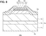
- FIG. 8 is a schematic cross-sectional view of a semiconductor device 100a according to the comparative embodiment. Members and structures of the comparative embodiment corresponding to the first embodiment will be described, with using reference numbers adding "a" to the reference numbers of the first embodiment.
- the semiconductor device 100a according to the comparative embodiment differs from the semiconductor device 100 according to the first embodiment, in a point that a p-type semiconductor layer 20a has a laminated structure in which a p-type GaN layer 22a and a p-type GaN layer 21a are laminated.
- the p-type GaN layer 22a is a layer (p layer) added with Mg at a concentration of 1 ⁇ 10 18 cm -3 for example, and has a thickness of 400 nm for example.
- the p-type GaN layer 21a is a layer (p ++ layer) added with Mg at a concentration of 2 ⁇ 10 20 cm -3 for example, and has a thickness of 30 nm for example.
- a p-type GaN-based semiconductor layer is used, whose p-type impurity concentration is suppressed to 10 19 cm -3 order at most, namely, less than 1 ⁇ 10 20 cm -3 , from a viewpoint of suppressing a deterioration of a crystal quality.
- the p-type GaN-based semiconductor layer whose p-type impurity concentration is 10 20 cm -3 or more order, namely, 1 ⁇ 10 20 cm -3 or more, cannot be utilized for forming pn-junction that functions as the diode, because it has a poor crystal quality due to a high impurity concentration.
- the p-type GaN-based semiconductor layer with a thickness of about several hundred nm is used, from a viewpoint of improving the reverse breakdown voltage. It is conceivable that the p-type GaN-based semiconductor layer with a thickness of less than 100 nm cannot be utilized for forming pn-junction that function as the diode because it is too thin and cannot ensure the reverse breakdown voltage.
- the p-type GaN layer (p layer) 22a is laminated directly on an n-type semiconductor layer 10a, the p-type GaN layer 22a being added with Mg at a concentration of 1 ⁇ 10 18 cm -3 and having a thickness of 400 nm.
- pn-junction is formed by the p-type GaN layer (p layer) 22a whose p-type impurity concentration is suppressed to less than 1 ⁇ 10 20 cm -3 and the n-type semiconductor layer 10a.
- a p-side electrode 40a is provided on an upper surface of the p-type GaN layer (p ++ layer) 21a added with Mg at a concentration of 2 ⁇ 10 20 cm -3 and having a thickness of 30 nm, namely, the p-type GaN layer (p ++ layer) 21a whose p-type impurity concentration is 1 ⁇ 10 20 cm -3 or more.
- the p-type GaN layer (p ++ layer) 21a is laminated on the p-type GaN layer (p layer) 22a, for the purpose of forming an excellent ohmic contact with the p-side electrode 40a.
- the p-type GaN layer (p ++ layer) 21a is provided for the purpose of forming the excellent ohmic contact with the p-side electrode 40a, and is not provided for the purpose of forming pn-junction.
- the semiconductor device 100 according to the embodiment will be further described hereafter.
- a concentration of the p-type impurity added into the p-type GaN layer 21, namely, the p-type semiconductor layer 20, is preferably 1 ⁇ 10 20 cm -3 or more, more preferably 2 ⁇ 10 20 cm -3 or more.
- the p-side electrode 40 can be excellently in ohmic contact with the p-type GaN layer 21. Namely, pn-junction that functions excellently as the diode can be formed, and the excellent ohmic contact with the p-side electrode 40 can be obtained, using the p-type semiconductor layer 20 configured by the p-type GaN layer 21.
- the p-type semiconductor layer 20 can be configured without using the thick p-type GaN layer (p layer) 22a with a thickness of about several hundred nm required for the comparative embodiment.
- a configuration of the p-type semiconductor layer 20 can be simplified, and a manufacturing process of the p-type semiconductor layer 20 can be simplified. Further, the p-type semiconductor layer 20 can be thinned, a resistance due to the p-type semiconductor layer 20 during a forward operation can be reduced, and energy consumption can be reduced.
- the p-type impurity concentration is 1 ⁇ 10 20 cm -3 or more, a high reverse breakdown voltage of several hundred volt (V) to 1000 V or more can be obtained even when the thin p-type GaN layer 21 with a thickness of less than 100 nm is used.
- the p-type impurity concentration of the p-type GaN layer 21 may be more than 1 ⁇ 10 20 cm -3 .
- the p-type impurity concentration of the p-type GaN layer 21 is more preferably 2 ⁇ 10 20 cm -3 or more.
- the concentration of the p-type impurity added into the p-type GaN layer 21, namely, the p-type semiconductor layer 20 is preferably less than 1 ⁇ 10 21 cm -3 , more preferably 6 ⁇ 10 20 cm -3 or less, and further more preferably 3 ⁇ 10 20 cm -3 or less.
- the p-type impurity concentration increases, a surface flatness of the p-type GaN layer deteriorates.
- the surface flatness of the p-type GaN layer deteriorates excessively, the p-type GaN layer cannot be formed into a film shape covering an entire surface of a base.
- the present inventors performed an experiment in which the p-type GaN layer with the Mg-concentration of 6 ⁇ 10 20 cm -3 and the thickness of 30 nm was grown. As a result, irregularities with a deepness of about 30 nm was observed on a crystal surface.
- the present inventors performed an experiment in which the p-type GaN layer with the Mg-concentration of 3 ⁇ 10 20 cm -3 and the thickness of 30 nm was grown. As a result, an abnormal growth did not occur, and the surface flatness was improved as compared to a case that Mg-concentration is 6 ⁇ 10 20 cm -3 . Even when Mg-concentration is the same as that of the above experiments, the surface flatness is expected to improve to some extent by optimizing a growth condition.
- the p-type impurity concentration of the p-type GaN layer 21 is 10 20 cm -3 order, namely, when the p-type impurity concentration is less than 1 ⁇ 10 21 cm -3 , the p-type GaN layer 21 can be formed into a film shape covering the entire surface of the base.
- the p-type impurity concentration of the p-type GaN layer 21 is more preferably 6 ⁇ 10 20 cm -3 or less from a viewpoint of improving the surface flatness, and further more preferably 3 ⁇ 10 20 cm -3 or less from a viewpoint of more improving the surface flatness and facilitating a film formation.
- a thickness of the p-type GaN layer 21, namely, the p-type semiconductor layer 20 is preferably less than 100 nm, and more preferably 30 nm or less.
- the thickness of the p-type GaN layer 21 is preferably less than 100 nm, and more preferably 30 nm or less.
- the p-type GaN layer 21 has the thin thickness of less than 100 nm, also from a viewpoint of facilitating a patterning which is performed for removing an entire surface of an unnecessary portion of the p-type GaN layer 21 when forming the mesa structure or JBS-diode described later, etc., for example.
- the thickness of the p-type GaN layer 21, namely, the p-type semiconductor layer 20 is preferably 2 nm or more, and more preferably 10 nm or more.
- a depletion layer extends from the pn-junction interface toward both the n-type semiconductor layer 10 side and the p-type semiconductor layer 20 side, namely, toward both an n-type GaN layer 13 side and a p-type GaN layer 21 side.
- a ratio between a thickness of the depletion layer extending toward the n-type GaN layer 13 side and a thickness of the depletion layer extending toward the p-type GaN layer 21 side is inversely proportional to a ratio between a donor concentration in the n-type GaN layer 13 and an acceptor concentration in the p-type GaN layer 21. Therefore, as the acceptor concentration in the p-type GaN layer 21 is higher, namely, as the p-type impurity concentration is higher, the thickness of the depletion layer extending toward the p-type GaN layer 21 side becomes thin.
- the p-type GaN layer 21 is configured to have a thickness that the depletion layer does not reach the p-side electrode 40 when applying the reverse voltage, it is possible to ensure the reverse breakdown voltage of the p-type GaN layer 21.
- the present inventors estimated the acceptor concentration when the Mg-concentration of the p-type GaN layer was 2 ⁇ 10 20 cm -3 , based on a reverse breakdown voltage of manufactured pn-junction diode. As a result, it was found that the acceptor concentration of about 5 ⁇ 10 19 cm -3 can be expected.
- the present inventors estimated the thickness of the depletion layer extending toward the p-type GaN layer side, when the acceptor concentration of the p-type GaN layer was 5 ⁇ 10 19 cm -3 , the donor concentration of the n-type GaN layer was 1 ⁇ 10 16 cm -3 , and the reverse applied voltage was 1000 V. As a result, it was found that the thickness of the depletion layer extending toward the p-type GaN layer side was about 2 nm.
- a ratio of the thickness of the depletion layer extending toward the p-type GaN layer side to the thickness of the depletion layer extending toward the n-type GaN layer side is 1/5000.
- the thickness of the depletion layer on the p-type GaN layer side is estimated to be about 4 nm. Further, when the Mg-concentration of the p-type GaN layer is 1 ⁇ 10 20 cm -3 and the reverse voltage is 500 V, the thickness of the depletion layer on the p-type GaN layer side is estimated to be about 2 nm.
- the thickness of the p-type GaN layer 21 is preferably 2 nm or more from a viewpoint of obtaining the high reverse breakdown voltage of about 500 V or more for example, and more preferably 10 nm or more from a viewpoint of more improving the reverse breakdown voltage.
- the p-type impurity concentration of the p-type GaN layer 21 is 1 ⁇ 10 20 cm -3 or more, the high reverse breakdown voltage of several hundred V to 1000 V or more can be obtained even when using the thin p-type GaN layer 21 with the thickness of about several nm to several ten nm (namely, the thickness of less than 100 nm). For example, as shown in experimental results described later, it is confirmed that the reverse breakdown voltage of at least 400 V or more can be obtained.
- a ratio of the concentration of the p-type impurity to the concentration of the n-type impurity is preferably 10000 times or more, the p-type impurity being added into the p-type semiconductor layer 20, and the n-type impurity being added into a portion of the n-type semiconductor layer 10 where pn-junction with the p-type semiconductor layer 20 is formed.
- a ratio of the p-type impurity concentration to the n-type impurity concentration is preferably 10000 times or more, the p-type impurity being added into the p-type GaN layer 21, and the n-type impurity being added into the n-type GaN layer 13.
- the ratio between the thickness of the depletion layer extending toward the n-type GaN layer 13 side and the thickness of the depletion layer extending toward the p-type GaN layer 21 side is inversely proportional to the ratio between the donor concentration in the n-type GaN layer 13 and the acceptor concentration in the p-type GaN layer 21. Therefore, from a viewpoint that the p-type GaN layer 21 is thinned while obtaining the high reverse breakdown voltage, the ratio of the p-type impurity concentration to the n-type impurity concentration is preferably 10000 times or more, the p-type impurity being added into the p-type GaN layer 21, and the n-type impurity being added into the n-type GaN layer 13.
- a positive hole concentration in the p-type GaN layer 21, namely, the p-type semiconductor layer 20 is preferably 1 ⁇ 10 16 cm -3 or more.
- the present inventors estimated the positive hole concentration when the Mg-concentration of the p-type GaN layer was 2 ⁇ 10 20 cm -3 . As a result, it was found that the positive hole concentration was about 7 ⁇ 10 16 cm -3 . Thereby, the positive hole concentration of the p-type GaN layer 21 is at least 1 ⁇ 10 16 cm -3 or more.
- the positive hole concentration of the p-type GaN layer 21 is preferably 1 ⁇ 10 16 cm -3 or more, from a viewpoint of obtaining the p-type GaN layer 21 with a low resistance.
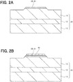
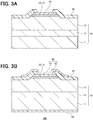
- FIGs. 2A , 2B , 3A, and 3B are schematic cross-sectional views showing a manufacturing process of the semiconductor device 100 according to the first embodiment.
- FIG. 2A will be referenced.
- the n-type GaN layer 12 is grown on the n-type GaN substrate 11, and the n-type GaN layer 13 is grown on the n-type GaN layer 12, to thereby form the n-type semiconductor layer 10.
- the p-type GaN layer 21 is grown on the n-type semiconductor layer 10, namely, on the n-type GaN layer 13, to thereby form the p-type semiconductor layer 20.
- the impurity concentration added into each layer, and the thickness of each layer, etc., are described above for example.
- a growth method and a raw material of each layer are not particularly limited.
- an organic metal vapor phase epitaxy (MOVPE) can be used as the growth method.
- Trimethylgallium (TMG) for example can be used as a Ga-source
- ammonia (NH 3 ) for example can be used as an N-source
- mono-silane (SiH 4 ) for example can be used as a Si-source
- bis-cyclopentadienyl-magnesium (Cp 2 Mg) for example can be used as an Mg-source.
- a semiconductor laminate is prepared, in which the p-type semiconductor layer 20 is laminated on the n-type semiconductor layer 10, and thereafter the mesa structure is formed by etching using a mask covering a portion on the upper surface of the p-type GaN layer 21 constituting the upper surface of the mesa structure.
- FIG. 2B will be referenced.
- a resist pattern having an opening in a formation area of the p-side bottom electrode 41 is formed, and then an electrode material for forming the p-side bottom electrode 41 is deposited. Then, the p-side bottom electrode 41 is formed by lift-off to remove an unnecessary portion of the electrode material together with the resist pattern.
- the material and the thickness of the p-side bottom electrode 41, etc., are described above for example.
- FIG. 3A will be referenced.
- An insulating material for forming the protective film 50 is deposited on an entire surface on a mesa structure side (the p-type semiconductor layer 20 side). Then, a resist pattern is formed, having an opening on the p-side bottom electrode 41, and thereafter the protective film 50 is formed by exposing the p-side bottom electrode 41 by removing an unnecessary portion of the insulating material using etching.
- the material and the thickness of the protective film 50, etc., are described above for example.
- FIG. 3B will be referenced.
- An electrode material for forming the n-side electrode 30 is deposited on an entire surface opposite to the mesa structure (on an entire surface on the n-type semiconductor layer 10 side), to thereby form the n-side electrode 30.
- the material and the thickness of the n-side electrode 30, etc., are described above for example.
- a resist pattern is formed on the upper surface of the mesa structure side (the p-type semiconductor layer 20 side), the resist pattern having an opening in a formation area of the p-side top electrode 42 is formed, and then an electrode material for forming the p-side top electrode 42 is deposited. Then, the p-side top electrode 42 is formed by lift-off to remove an unnecessary portion of the electrode material together with the resist pattern.
- the material and the thickness of the p-side top electrode 42, etc., are described above for example. In this manner, the semiconductor device 100 according to the first embodiment is manufactured.
- An n-type GaN layer with a Si-concentration of 2 ⁇ 10 18 cm -3 and a thickness of 2 ⁇ m was grown on an n-type GaN substrate with a Si-concentration of 2 ⁇ 10 18 cm -3 and a thickness of 400 ⁇ m, and an n-type GaN layer with a Si-concentration of 1.2 ⁇ 10 16 cm -3 and a thickness of 5 ⁇ m was grown on the n-type GaN layer, to thereby form an n-type semiconductor layer.
- a p-type GaN layer with an Mg-concentration of 2 ⁇ 10 20 cm -3 and a thickness of 20 nm was grown on the n-type semiconductor layer, to thereby form a p-type semiconductor layer.
- Electrodes not having a field plate electrode portion and having a diameter of 60 ⁇ m, 100 ⁇ m, and 200 ⁇ m respectively were formed as the p-side electrode. In this way, samples of a pn-junction diode were manufactured.
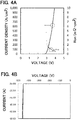
- FIG. 4A is a graph for the sample with the p-side electrode diameter of 100 ⁇ m, showing a current-voltage characteristic in a forward direction. It is found that the current-voltage characteristic in the forward direction showing a rise at a voltage of about 3 V is obtained. It is noted that an on-resistance is also shown in FIG. 4A .
- FIG. 4B is a graph for each sample with p-side electrode diameter of 60 ⁇ m, 100 ⁇ m, and 200 ⁇ m, showing current-voltage characteristic in the backward direction. It is found that the current-voltage characteristics in the backward direction with the reverse breakdown voltage of 400 V or more (about 450 V to 460 V) are obtained, even when the samples have any one of the above electrode diameters.
- a sample (other sample) has a p-type semiconductor layer configured by a p-type GaN layer with an Mg-concentration of 2 ⁇ 10 20 cm -3 and a thickness of 10 nm.
- a sample (other sample) has a p-type semiconductor layer configured by a p-type GaN layer with an Mg-concentration of 2 ⁇ 10 20 cm -3 and a thickness of 30 nm.
- Current-voltage characteristics in the forward and backward directions were also measured for these other samples.
- the present inventors found that pn-junction using the p-type GaN-based semiconductor layer added with the p-type impurity at the concentration of 1 ⁇ 10 20 cm -3 or more, functioned excellently as the diode. Further, the present inventors found that pn-junction that functions excellently as the diode with the high reverse breakdown voltage of several hundred V or more can be formed, even though such a p-type GaN-based semiconductor layer had an extremely thin thickness of less than 100 nm.
- FIG. 5 is a schematic cross-sectional view of the semiconductor device 100 according to the second embodiment, and also shows a schematic planar view showing a shape of a p-side bottom electrode 41 on an upper side in the drawing.
- a member and a structure according to the second embodiment corresponding to the first embodiment will be described, using the same numerals as the first embodiment.
- JBS Junction Barrier Schottky
- the semiconductor device 100 according to the second embodiment differs from the semiconductor device 100 according to the first embodiment, in a point that the p-type semiconductor layer 20 is patterned so as to partially remove the entire thickness, and the p-side electrode 40 is disposed in contact with the p-type semiconductor layer 20 and the n-type semiconductor layer 10.
- the p-type semiconductor layer 20, namely, the p-type GaN layer 21 is patterned so that a plurality of circular portions 121 are left concentrically for example, inside of the p-side bottom electrode 41. At a gap between the adjacent circular portions 121, the entire thickness of the p-type GaN layer 21 is removed, and the upper surface of the n-type semiconductor layer 10, namely, an upper surface of the n-type GaN layer 13 is exposed.
- a structure in which the p-type GaN layer 21 and the n-type GaN layer 13 are arranged alternately in a radial direction of the circular portion 121 in a planar view.
- a disposition area of the p-type GaN layer 21 is indicated by hatching, and a disposition area of the n-type GaN layer 13 is indicated as an open area.
- a width of the circular portion 121 is about 1 ⁇ m to 10 ⁇ m for example, and a gap width between the adjacent circular portions 121 is about 1 ⁇ m to 10 ⁇ m for example.
- the p-side bottom electrode 41 namely, the p-side electrode 40 is in contact with the p-type GaN layer 21, namely, the p-type semiconductor layer 20 on the upper surface of the p-type GaN layer 21, and is in contact with the n-type GaN layer 13, namely, the n-type semiconductor layer 10 on the upper surface of the n-type GaN layer 13.
- a structure is configured, in which the p-side electrode 40 is disposed in contact with the p-type semiconductor layer 20 and the n-type semiconductor layer 10.
- a structure of the p-side top electrode 42 is similar to the first embodiment.
- the JBS diode is configured.
- a proportion of an area where the p-side electrode 40 is in contact with the p-type semiconductor layer 20, based on the sum of an area where the p-side electrode 40 is in contact with the p-type semiconductor layer 20 and an area where the p-side electrode 40 is in contact with the n-type semiconductor layer 10, is preferably 20 % or more and 80 % or less, from a viewpoint of obtaining an excellent operation as the JBS diode.
- the concentric circular shape pattern is exemplified as an aspect of the patterning of the p-type semiconductor layer 20 to configure the JBS diode.
- other pattern such as a stripe shape may be used for the above patterning, as required.
- the p-side bottom electrode 41 is in contact with the p-type GaN layer 21 on the upper surface of the p-type GaN layer 21, and is in contact with the n-type GaN layer 13 on the upper surface of the n-type GaN layer 13 exposed by patterning the p-type GaN layer 21.
- the upper surface of the n-type semiconductor layer 10 in contact with the p-side electrode 40 is disposed at a lower position (a position closer to the substrate 11) than the upper surface of the p-type semiconductor layer 20 in contact with the p-side electrode 40 (a height of the upper surface of the p-type semiconductor layer 20 in contact with the p-side electrode 40, differs from a height of the upper surface of the n-type semiconductor layer 10 in contact with the p-side electrode 40).
- the p-type GaN layer 21 can be formed to have a thin thickness of less than 100 nm. Since the p-type GaN layer 21 is thin, it is easy to perform the patterning of removing the entire thickness of the unnecessary portion of the p-type GaN layer 21, and easy to manufacture the JBS diode.
- the p-type GaN layer 21 Since the p-type GaN layer 21 is thin, it is easy to remove the entire thickness of the unnecessary portion of the p-type GaN layer 21 by a wet etching.
- An anodization for example can be used as the wet etching.
- the anodization is preferable because the p-type GaN layer 21 can be selectively etched to the n-type GaN layer 13.
- a defect density of a portion covering with the p-type GaN layer 21 is equal to a defect density of an exposed portion by removing the p-type GaN layer 21 (a portion in contact with the p-side electrode 40).
- equal defect density means that an increase of the defect density of the exposed portion by removing the p-type GaN layer 21 (portion in contact with the p-side electrode 40), from the defect density of the portion covered with the p-type GaN layer 21, is 10 % or less.
- a dry etching may be used for the patterning of the p-type GaN layer 21, as required. Since the p-type GaN layer 21 is thin, it is possible to perform the processing under a mild condition for a short time and to suppress the damage to the exposed n-type GaN layer 13 even when using the dry etching.
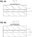
- FIG. 6A and FIG. 6B are schematic cross-sectional views showing a manufacturing process of the semiconductor device 100 according to the second embodiment.
- a semiconductor laminate is prepared, in which the n-type semiconductor layer 10 and the p-type semiconductor layer 20 are laminated, and the mesa structure is formed, similarly to the process described in the first embodiment with reference to FIG. 2A .
- FIG. 6A will be referenced.
- a mask is formed, which has an opening in an area where the n-type GaN layer 13 on the p-type GaN layer 21 is exposed, and a patterning for removing the p-type GaN layer 21 in an opening portion by etching is performed.
- a wet etching is preferably used for the patterning of the p-type GaN layer 21, and the anodization is preferably used as the wet etching.
- the patterning of the p-type GaN layer 21 using the anodization is performed as follows for example.
- a SiO 2 -film to be a mask is formed on the p-type GaN layer 21 by a spin-on-glass, a PECVD method, or a sputtering method.
- a resist pattern for JBS is formed, the SiO 2 -film is etched using a buffered hydrofluoric acid (BHF), and the mask for the anodization is formed.
- BHF buffered hydrofluoric acid
- the n-type GaN substrate 11, the n-type GaN layer 12, the n-type GaN layer 13 (n-type semiconductor layer 10), and a side of the p-type GaN layer 21 (p-type semiconductor layer 20) is prevented from being brought into contact with an electrolytic solution.
- the p-type GaN layer 21 and an anode electrode are immersed in the electrolytic solution.
- a Pt-net is used as the anode electrode, and a silver-silver chloride electrode is used as a reference electrode.
- the anodization is performed by applying a voltage between the p-type semiconductor layer 20 (the p-type GaN layer 21) and the n-type semiconductor layer 10 (the n-type GaN substrate 11, the n-type GaN layer 12, and the n-type GaN layer 13), through the electrolytic solution and the anode electrode.
- An electrode may be formed on a back surface of the n-type GaN substrate 11 after forming the SiO 2 -mask, and may be used as a cathode electrode.
- FIG. 6B will be referenced. Similarly to the process described in the first embodiment with reference to FIG. 2B , a resist pattern having an opening in a formation area of the p-side bottom electrode 41 is formed, and an electrode material for forming the p-side bottom electrode 41 is deposited. Then, the p-side bottom electrode 41 is formed by lift-off to remove an unnecessary portion of the electrode material together with the resist pattern.
- the electrode material is deposited not only on the upper surface of the p-type GaN layer 21 but also on the upper surface of the n-type GaN layer 13 exposed at the gap of the p-type GaN layer 21.
- the p-side bottom electrode 41 is formed so as to have a shape extending from a surface of the p-type GaN layer 21 to a surface of the exposed n-type GaN layer 13, and therefore the p-side bottom electrode 41 in contact with both the p-type GaN layer 21 and the n-type GaN layer 13 is formed.
- the protective film 50, the n-side electrode 30, and the p-side top electrode 42 are formed, similarly to the process described in the first embodiment with reference to FIG. 3A and FIG. 3B .
- the semiconductor device 100 according to the second embodiment is manufactured.
- a semiconductor laminate 110 may be prepared, in which the n-type semiconductor layer 10 and the p-type semiconductor layer 20 are laminated in advance.
- the semiconductor laminate 110 may be prepared, in which the n-type semiconductor layer 10 and the p-type semiconductor layer 20 are laminated.
- this n-type semiconductor layer 10 contains the GaN-based semiconductor.
- this p-type semiconductor layer 20 is laminated directly on the n-type semiconductor layer 10, and contains the GaN-based semiconductor added with the p-type impurity at a concentration of 1 ⁇ 10 20 cm -3 or more.
- the semiconductor laminate 110 is a semiconductor laminate capable of functioning as the pn-junction diode by applying the voltage to pn-junction formed by the p-type semiconductor layer 20 and the n-type semiconductor layer 10.
- FIG. 7 is a schematic cross-sectional view showing an example of the semiconductor laminate 110.
- the n-type semiconductor layer 10 is formed by growing the n-type GaN layer 12 and the n-type GaN layer 13 on the n-type GaN substrate 11.
- the p-type semiconductor layer 20 is formed by growing the p-type GaN layer 21 on the n-type semiconductor layer 10, namely, on the n-type GaN layer 13.
- the p-type GaN layer 21, namely, the p-type semiconductor layer 20 is formed on an entire surface of the n-type GaN layer 13, namely, of the n-type semiconductor layer 10.
- the pn-junction interface is flat, which is formed by the p-type GaN layer 21 and the n-type GaN layer 13, namely, is formed by the p-type semiconductor layer 20 and the n-type semiconductor layer 10. (At least a part of) the upper surface of the p-type GaN layer 21, namely, the upper surface of the p-type semiconductor layer 20 is prepared as a formation area (contact area) of the p-side electrode 40.
- the semiconductor laminate 110 is used, in which the n-type semiconductor layer 10 and the p-type semiconductor layer 20 are laminated in advance, it is possible to omit a process in which a semiconductor layer such as the n-type GaN layer 12 or the p-type GaN layer 21 is epitaxially grown, and it is easy to manufacture the semiconductor device 100.
- the p-type GaN layer 21, namely, the p-type semiconductor layer 20 can be patterned in a prescribed shape using the wet etching by the anodization for example as described above.
- the semiconductor laminate 110 itself may be distributed on a market. Namely, for example, the semiconductor laminate 110 may be distributed on the market in a state that the n-side electrode 30 connected electrically to the n-type semiconductor layer 10 or the p-side electrode 40 connected electrically to the p-type semiconductor layer 20, etc., is not formed, and for example, in a state that the upper surface of the p-type semiconductor layer 20 is an upper surface of the semiconductor laminate 110.
- the semiconductor laminate 110 may be used for manufacturing a semiconductor device having a configuration other than the semiconductor device 100 according to the first embodiment or the second embodiment.
- a diode using the GaN-based semiconductor can be formed by pn-junction using the p-type semiconductor layer whose p-type impurity concentration is 1 ⁇ 10 20 cm -3 or more. Therefore, the p-type GaN-based semiconductor layer whose p-type impurity concentration is less than 1 ⁇ 10 20 cm -3 (for example, about 10 18 cm -3 ), is unnecessary. Thereby, the configuration of the p-type semiconductor layer can be simplified, and the manufacturing process of the p-type semiconductor layer can be simplified. Further, the p-type semiconductor layer can be thinned, the resistance due to the p-type semiconductor layer during the forward operation can be reduced, and the energy consumption can be reduced.
- a semiconductor device that functions as a pn-junction diode, including:
- the semiconductor device according to the supplementary description 1 or 2, wherein the concentration of the p-type impurity added into the second semiconductor layer is preferably less than 1 ⁇ 10 21 cm -3 , more preferably 6 ⁇ 10 20 cm -3 or less, and further more preferably 3 ⁇ 10 20 cm -3 or less.
- a thickness of the second semiconductor layer is preferably less than 100 nm, and more preferably 30 nm or less.
- a thickness of the second semiconductor layer is preferably 2 nm or more, and more preferably 10 nm or more.
- the semiconductor device according to any one of the supplementary descriptions 1 to 5, wherein an n-type impurity is added into the first semiconductor layer; and a ratio of the concentration of the p-type impurity to the concentration of the n-type impurity is 10000 times or more, the p-type impurity being added into the second semiconductor layer, and the n-type impurity added into a portion of the first semiconductor layer where pn-junction with the second semiconductor layer is formed.
- a positive hole concentration in the second semiconductor layer is 1 ⁇ 10 16 cm -3 or more.
- a breakdown voltage is 400 V or more when a reverse voltage is applied.
- an upper surface of the second semiconductor layer is disposed at a higher position than an upper surface of the first semiconductor layer (a height of an upper surface of the second semiconductor layer differs from a height of an upper surface of the first layer).
- the semiconductor device according to any one of the supplementary descriptions 1 to 9, wherein the second electrode is disposed in contact with the second semiconductor layer and not in contact with the first semiconductor layer.
- the semiconductor device according to any one of the supplementary descriptions 1 to 9, wherein the second electrode is disposed in contact with the second semiconductor layer and the first semiconductor layer; and the semiconductor device is a Junction Barrier Schottky diode that functions as the pn-junction diode and functions as a Schottky barrier diode.
- a proportion of an area where the second electrode is in contact with the second semiconductor layer, based on the sum of an area where the second electrode is in contact with the second semiconductor layer and an area where the second electrode is in contact with the first semiconductor layer, is 20 % or more.
- a proportion of an area where the second electrode is in contact with the second semiconductor layer, based on the sum of an area where the second electrode is in contact with the second semiconductor layer and an area where the second electrode is in contact with the first semiconductor layer, is 80 % or less.
- the semiconductor device according to any one of the supplementary descriptions 11 to 14, wherein the upper surface of the first semiconductor layer in contact with the second electrode, is disposed at a lower position than the upper surface of the second semiconductor layer in contact with the second electrode (a height of the upper surface of the first semiconductor layer in contact with the second electrode, differs from a height of the upper surface of the second semiconductor layer in contact with the second electrode).
- a method for manufacturing a semiconductor device that functions as a pn-junction diode including:
- the method according to the supplementary description 16 further including removing partially an entire thickness of the second semiconductor layer by a wet etching, and exposing the first semiconductor layer, wherein forming the second electrode is forming the second electrode so as to have a shape extending from a surface of the second semiconductor layer to a surface of the first semiconductor layer which is exposed by the wet etching, and thereby forming the second electrode disposed in contact with the second semiconductor layer and the first semiconductor layer; and a Junction Barrier Schottky diode that functions as the pn-junction diode and functions as a Schottky Barrier diode is manufactured as the semiconductor device.
- a semiconductor laminate capable of functioning as a pn-junction diode including:
Landscapes
- Chemical & Material Sciences (AREA)
- Inorganic Chemistry (AREA)
- General Chemical & Material Sciences (AREA)
- Chemical Kinetics & Catalysis (AREA)
- Engineering & Computer Science (AREA)
- Materials Engineering (AREA)
- Mechanical Engineering (AREA)
- Metallurgy (AREA)
- Organic Chemistry (AREA)
- Electrodes Of Semiconductors (AREA)
- Led Devices (AREA)
- Chemical Vapour Deposition (AREA)
- Recrystallisation Techniques (AREA)
Abstract
Description
- The present disclosure relates to a semiconductor device and a method for manufacturing the same.
- Attention has been payed to gallium nitride (GaN)-based semiconductors, as a high-frequency electronic element material with a high breakdown voltage and a high output, and a light emitting element material capable of emitting light from red to ultraviolet.
- When pn-junction that functions as a diode is formed using the GaN-based semiconductor, for example, a p-type semiconductor layer is configured by a laminated structure of a p-type GaN-based semiconductor layer whose p-type impurity concentration is about 1018 cm-3 and whose thickness is about several hundred nanometers (nm), and a p-type GaN-based semiconductor layer whose p-type impurity concentration is about 1020 cm-3 and whose thickness is about several ten nm (see
patent document 1, for example). - [Patent Document 1] Japanese Patent Laid Open Publication No.
2015-149391 - Simplifying a configuration of the p-type semiconductor layer is preferable from a viewpoint of simplifying a manufacturing process of the p-type semiconductor layer, and the like.
- An object of the present disclosure is to provide a semiconductor device capable of functioning as a pn-junction diode using the GaN-based semiconductor and capable of simplifying a configuration of the p-type semiconductor layer, a method for manufacturing the same, and a semiconductor laminate that can be used therefore.
- According to an aspect of the present disclosure, there is provided a semiconductor device that functions as a pn-junction diode, including:
- a first semiconductor layer with n-type conductivity, containing a gallium nitride-based semiconductor;
- a second semiconductor layer with p-type conductivity, which is laminated directly on the first semiconductor layer, and contains a gallium nitride-based semiconductor added with a p-type impurity at a concentration of 1 × 1020 cm-3 or more;
- a first electrode disposed in contact with the first semiconductor layer; and
- a second electrode disposed in contact with the second semiconductor layer.
- According to another aspect of the present disclosure, there is provided a method for manufacturing a semiconductor device that functions as a pn-junction diode, including:
- preparing a semiconductor laminate including a first semiconductor layer with n-type conductivity, which contains a gallium nitride-based semiconductor, and a second semiconductor layer with p-type conductivity, which is laminated directly on the first semiconductor layer and contains a gallium nitride-based semiconductor added with a p-type impurity at a concentration of 1 × 1020 cm-3 or more;
- forming a first electrode disposed in contact with the first semiconductor layer; and
- forming a second electrode disposed in contact with the second semiconductor layer.
- According to further another aspect of the present disclosure, there is provided a semiconductor laminate capable of functioning as a pn-junction diode, including:
- a first semiconductor layer with n-type conductivity, comprising (containing) a gallium nitride-based semiconductor; and
- a second semiconductor layer with p-type conductivity, which is laminated directly on the first semiconductor layer, and contains a gallium nitride-based semiconductor added with a p-type impurity at a concentration of 1 × 1020 cm-3 or more.
- A diode using the gallium nitride-based semiconductor can be formed by pn-junction using the p-type semiconductor layer (the second semiconductor layer) whose p-type impurity concentration is 1 × 1020 cm-3 or more. Therefore, a p-type gallium nitride-based semiconductor layer whose p-type impurity concentration is less than 1 × 1020 cm-3 (for example, about 1018 cm-3), is unnecessary. Thereby, the configuration of the p-type semiconductor layer can be simplified, and the manufacturing process of the p-type semiconductor layer can be simplified. Further, the p-type semiconductor layer can be thinned, a resistance due to the p-type semiconductor layer during a forward operation can be reduced, and energy consumption can be reduced.
-
-
FIG. 1 is a schematic cross-sectional view of a semiconductor device according to a first embodiment of the present disclosure. -
FIGs. 2A and 2B are schematic cross-sectional views showing a manufacturing process of the semiconductor device according to the first embodiment. -
FIGs. 3A and 3B are schematic cross-sectional views showing a manufacturing process of the semiconductor device according to the first embodiment. -
FIG. 4A is a graph for manufactured samples of the pn-junction diode, showing a current-voltage characteristic in a forward direction, andFIG. 4B is a graph for manufactured samples of the pn-junction diode, showing a current-voltage characteristic in a backward direction. -
FIG. 5 is a schematic cross-sectional view of a semiconductor device according to a second embodiment, and a schematic planar view showing a shape of a p-side bottom electrode. -
FIGs. 6A and 6B are schematic cross-sectional views showing a manufacturing process of the semiconductor device according to the second embodiment. -
FIG. 7 is a schematic cross-sectional view showing an example of a semiconductor laminate. -
FIG. 8 is a schematic cross-sectional view of a semiconductor device according to a comparative embodiment. - A
semiconductor device 100 according to a first embodiment of the present disclosure will be exemplarily described, with reference toFIG. 1. FIG. 1 is a schematic cross-sectional view of thesemiconductor device 100 according to the first embodiment. - The
semiconductor device 100 includes asemiconductor layer 10 with n-type conductivity, a semiconductor layer 20 with p-type conductivity, anelectrode 30, and anelectrode 40, and functions as a pn-junction diode. Thesemiconductor layer 10 contains a gallium nitride (GaN)-based semiconductor. The semiconductor layer 20 is laminated directly on the n-type semiconductor layer 10, and contains a GaN-based semiconductor added with a p-type impurity at a concentration of 1 × 1020 cm-3 or more. Theelectrode 30 is disposed in contact with thesemiconductor layer 10. Theelectrode 40 is disposed in contact with the semiconductor layer 20. Thesemiconductor layer 10 is also referred to as an n-type semiconductor layer 10, the semiconductor layer 20 is also referred to as a p-type semiconductor layer 20, theelectrode 30 is also referred to as an n-side electrode 30, and theelectrode 40 is also referred to as a p-side electrode 40. - In an embodiment described hereafter, for example, GaN is used as the GaN-based semiconductor, namely, semiconductor including gallium (Ga) and nitrogen (N). However, the GaN-based semiconductor is not limited to GaN. A semiconductor including a group-III element other than Ga in addition to Ga and N as required can be used as the GaN-based semiconductor.
- For example, aluminum (Al) and indium (In) are used as the group-III element other than Ga. However, from a viewpoint of reducing a lattice strain, the group-III element other than Ga is preferably contained so that a lattice mismatch with GaN of the GaN-based semiconductor containing the group-III element other than Ga is 1 % or less. For example, a content of Al in AlGaN allowed in the GaN-based semiconductor is 40 atomic % or less in the group-III element. Further, for example, a content of In in InGaN allowed in the GaN-based semiconductor is 10 atomic % or less in the group-III element. It is also acceptable to use InAlGaN in combination of GaN and InAlN having In content in InAlN is 10 atomic % or more and 30 atomic % or less in the group-III element, at arbitrary composition. When Al and In compositions are within the above range, the lattice strain from GaN is hardly increased, and therefore cracks hardly occur.
- For example, the n-
type semiconductor layer 10 has a laminated structure in which an n-type GaN substrate 11, an n-type GaN layer 12, and an n-type GaN layer 13 are laminated. The n-type GaN substrate 11 is a substrate added with silicon (Si) as an n-type impurity at a concentration of 2 × 1018 cm-3 for example, and having a thickness of 400 µm for example. The n-type GaN layer 12 is a layer (n layer) added with Si at a concentration of 2 × 1018 cm-3 for example, and having a thickness of 2 µm for example. The n-type GaN layer 13 is a layer (n- layer) added with Si at a concentration of 1.2 × 1016 cm-3 for example, and having a thickness of 13 µm for example. - A structure of the n-
type semiconductor layer 10 is not particularly limited. For example, the n-type semiconductor layer 10 may be configured including an undoped n-type GaN layer with the n-type conductivity although the n-type impurity is not added. - The p-type semiconductor layer 20 is laminated directly on the n-
type semiconductor layer 10, namely, directly on the n-type GaN layer (n- layer) 13. The p-type semiconductor layer 20 is configured by a p-type GaN layer 21. The p-type GaN layer 21 is a layer (p++ layer) added with magnesium (Mg) as the p-type impurity at a concentration of 2 × 1020 cm-3 for example, and having a thickness of 30 nm for example. - Pn-junction is formed by the p-type semiconductor layer 20 and the n-
type semiconductor layer 10, namely, by the p-type GaN layer 21 and the n-type GaN layer 13. Since the p-type semiconductor layer 20 is laminated on the n-type semiconductor layer 10, an upper surface of the p-type semiconductor layer 20 is disposed at a higher position (at a position farther away from the substrate 11) than an upper surface of the n-type semiconductor layer 10 (a height of the upper surface of the p-type semiconductor layer 20 differs from a height of the upper surface of the n-type semiconductor layer 10). Further, a pn-junction interface is flat. - The n-
side electrode 30 is provided on a lower surface of the n-type GaN substrate 11. Namely, the n-side electrode 30 is disposed in contact with the n-type semiconductor layer 10 on the lower surface of the n-type semiconductor layer 10. For example, the n-side electrode 30 is formed of a laminated film in which a titanium (Ti) layer with a thickness of 50 nm and an aluminum (Al) layer with a thickness of 250 nm are laminated in this order from an n-type semiconductor layer 10 side. - The p-
side electrode 40 is provided on an upper surface of the p-type GaN layer 21. Namely, the p-side electrode 40 is disposed in contact with the p-type semiconductor layer 20 on the upper surface of the p-type semiconductor layer 20. In thesemiconductor device 100 according to the first embodiment, the p-side electrode 40 is disposed in contact with the p-type semiconductor layer 20 and not in contact with the n-type semiconductor layer 10. - For example, the p-
side electrode 40 has a laminated structure in which a p-side bottom electrode 41 and a p-side top electrode 42 are laminated. The p-side bottom electrode 41 is provided on the upper surface of the p-type semiconductor layer 20 so as to be included in the p-type semiconductor layer 20 in a planar view. For example, the p-side bottom electrode 41 has a circular shape in planar view. For example, the p-side bottom electrode 41 is formed of a laminated film in which a palladium (Pd) layer with a thickness of 200 nm and a nickel (Ni) layer with a thickness of 100 nm are laminated in this order from a p-type semiconductor layer 20 side. The p-side top electrode 42 will be described in detail later. - The
semiconductor device 100 shown in the example has a mesa structure, and has an insulatingprotective film 50 provided so as to cover the upper surface of the n-type semiconductor layer 10 disposed at an outside of the mesa structure, a lateral surface of the mesa structure, and an edge portion of the upper surface of the p-type semiconductor layer 20 constituting an upper surface of the mesa structure. For example, theprotective film 50 is formed of a laminated film of a silicon oxide (SiO2) film by a spin-on-glass and a SiO2-film by a sputtering method. A thickness of theprotective film 50 is about 600 nm for example. - The
protective film 50 has an opening on the upper surface of the p-type semiconductor layer 20. An opening edge portion of theprotective film 50 is provided so as to ride on an edge portion of the p-side bottom electrode 41, and an upper surface of the p-side bottom electrode 41 is exposed in the opening of theprotective film 50. - The p-
side top electrode 42 is provided on the upper surface of the p-side bottom electrode 41 exposed in the opening of theprotective film 50, and extends on theprotective film 50 so as to reach the upper surface of the n-type semiconductor layer 10 at the outside of the mesa structure in a planar view. The p-side top electrode 42 functions as a field plate electrode portion for improving a breakdown voltage (reverse breakdown voltage) when applying a reverse voltage. For example, the p-side top electrode 42 is formed of a laminated film in which a Ti-layer with a thickness of 30 nm and an Al-layer with a thickness of 250 nm are laminated in this order from the p-type semiconductor layer 20 side. - A structure of the p-
side electrode 40 is not limited particularly. For example, the p-side electrode 40 may be not the laminated structure of the p-side bottom electrode 41 and the p-side top electrode 42 but a single layer structure. Further, for example, the p-side electrode 40 may not have the field plate electrode portion. However, it is preferable to have the field plate electrode portion, from a viewpoint of improving the reverse breakdown voltage. - The
semiconductor device 100 according to the embodiment has a characteristic that the p-type semiconductor layer 20 is configured by a p-type GaN-based semiconductor layer added with the p-type impurity at a concentration of 1 × 1020 cm-3 or more. Such a characteristic will be described hereafter while contrasting with a semiconductor device according to a comparative embodiment. -
FIG. 8 is a schematic cross-sectional view of asemiconductor device 100a according to the comparative embodiment. Members and structures of the comparative embodiment corresponding to the first embodiment will be described, with using reference numbers adding "a" to the reference numbers of the first embodiment. - The
semiconductor device 100a according to the comparative embodiment differs from thesemiconductor device 100 according to the first embodiment, in a point that a p-type semiconductor layer 20a has a laminated structure in which a p-type GaN layer 22a and a p-type GaN layer 21a are laminated. The p-type GaN layer 22a is a layer (p layer) added with Mg at a concentration of 1 × 1018 cm-3 for example, and has a thickness of 400 nm for example. The p-type GaN layer 21a is a layer (p++ layer) added with Mg at a concentration of 2 × 1020 cm-3 for example, and has a thickness of 30 nm for example. - When pn-junction that functions as a diode is formed using the GaN-based semiconductor, according to a common general technical knowledge, a p-type GaN-based semiconductor layer is used, whose p-type impurity concentration is suppressed to 1019 cm-3 order at most, namely, less than 1 × 1020 cm-3, from a viewpoint of suppressing a deterioration of a crystal quality. It is conceivable that the p-type GaN-based semiconductor layer whose p-type impurity concentration is 1020 cm-3 or more order, namely, 1 × 1020 cm-3 or more, cannot be utilized for forming pn-junction that functions as the diode, because it has a poor crystal quality due to a high impurity concentration.
- Further, according to a common general technical knowledge, the p-type GaN-based semiconductor layer with a thickness of about several hundred nm is used, from a viewpoint of improving the reverse breakdown voltage. It is conceivable that the p-type GaN-based semiconductor layer with a thickness of less than 100 nm cannot be utilized for forming pn-junction that function as the diode because it is too thin and cannot ensure the reverse breakdown voltage.
- Therefore, in the comparative embodiment, the p-type GaN layer (p layer) 22a is laminated directly on an n-
type semiconductor layer 10a, the p-type GaN layer 22a being added with Mg at a concentration of 1 × 1018 cm-3 and having a thickness of 400 nm. Namely, pn-junction is formed by the p-type GaN layer (p layer) 22a whose p-type impurity concentration is suppressed to less than 1 × 1020 cm-3 and the n-type semiconductor layer 10a. - A p-
side electrode 40a is provided on an upper surface of the p-type GaN layer (p++ layer) 21a added with Mg at a concentration of 2 × 1020 cm-3 and having a thickness of 30 nm, namely, the p-type GaN layer (p++ layer) 21a whose p-type impurity concentration is 1 × 1020 cm-3 or more. The p-type GaN layer (p++ layer) 21a is laminated on the p-type GaN layer (p layer) 22a, for the purpose of forming an excellent ohmic contact with the p-side electrode 40a. - As described above, in the comparative embodiment, the p-type GaN layer (p++ layer) 21a is provided for the purpose of forming the excellent ohmic contact with the p-
side electrode 40a, and is not provided for the purpose of forming pn-junction. - However, as shown in an experimental result described later, the present inventors found that pn-junction using a p-type GaN-based semiconductor layer added with the p-type impurity at a concentration of 1 × 1020 cm-3 or more, functions excellently as the diode, contrary to a common general technical knowledge. This disclosure is based on such a finding.
- The
semiconductor device 100 according to the embodiment will be further described hereafter. - A concentration of the p-type impurity added into the p-type GaN layer 21, namely, the p-type semiconductor layer 20, is preferably 1 × 1020 cm-3 or more, more preferably 2 × 1020 cm-3 or more.
- Since the p-type impurity concentration of the p-type GaN layer 21 is 1 × 1020 cm-3 or more, the p-
side electrode 40 can be excellently in ohmic contact with the p-type GaN layer 21. Namely, pn-junction that functions excellently as the diode can be formed, and the excellent ohmic contact with the p-side electrode 40 can be obtained, using the p-type semiconductor layer 20 configured by the p-type GaN layer 21. - Therefore, the p-type semiconductor layer 20 can be configured without using the thick p-type GaN layer (p layer) 22a with a thickness of about several hundred nm required for the comparative embodiment.
- Thereby, a configuration of the p-type semiconductor layer 20 can be simplified, and a manufacturing process of the p-type semiconductor layer 20 can be simplified. Further, the p-type semiconductor layer 20 can be thinned, a resistance due to the p-type semiconductor layer 20 during a forward operation can be reduced, and energy consumption can be reduced.
- Further, as described later in detail, since the p-type impurity concentration is 1 × 1020 cm-3 or more, a high reverse breakdown voltage of several hundred volt (V) to 1000 V or more can be obtained even when the thin p-type GaN layer 21 with a thickness of less than 100 nm is used.
- The p-type impurity concentration of the p-type GaN layer 21 may be more than 1 × 1020 cm-3.
- From a viewpoint of more thinning the thickness of the p-type GaN layer 21 capable of obtaining the high reverse breakdown voltage, the p-type impurity concentration of the p-type GaN layer 21 is more preferably 2 × 1020 cm-3 or more.
- The concentration of the p-type impurity added into the p-type GaN layer 21, namely, the p-type semiconductor layer 20 is preferably less than 1 × 1021 cm-3, more preferably 6 × 1020 cm-3 or less, and further more preferably 3 × 1020 cm-3 or less.
- Since the p-type impurity concentration increases, a surface flatness of the p-type GaN layer deteriorates. When the surface flatness of the p-type GaN layer deteriorates excessively, the p-type GaN layer cannot be formed into a film shape covering an entire surface of a base. The present inventors performed an experiment in which the p-type GaN layer with the Mg-concentration of 6 × 1020 cm-3 and the thickness of 30 nm was grown. As a result, irregularities with a deepness of about 30 nm was observed on a crystal surface. Further, the present inventors performed an experiment in which the p-type GaN layer with the Mg-concentration of 3 × 1020 cm-3 and the thickness of 30 nm was grown. As a result, an abnormal growth did not occur, and the surface flatness was improved as compared to a case that Mg-concentration is 6 × 1020 cm-3. Even when Mg-concentration is the same as that of the above experiments, the surface flatness is expected to improve to some extent by optimizing a growth condition.
- Therefore, it is conceivable that when the p-type impurity concentration of the p-type GaN layer 21 is 1020 cm-3 order, namely, when the p-type impurity concentration is less than 1 × 1021 cm-3, the p-type GaN layer 21 can be formed into a film shape covering the entire surface of the base. The p-type impurity concentration of the p-type GaN layer 21 is more preferably 6 × 1020 cm-3 or less from a viewpoint of improving the surface flatness, and further more preferably 3 × 1020 cm-3 or less from a viewpoint of more improving the surface flatness and facilitating a film formation.
- A thickness of the p-type GaN layer 21, namely, the p-type semiconductor layer 20 is preferably less than 100 nm, and more preferably 30 nm or less.
- When the p-type impurity concentration is 1 × 1020 cm-3 or more, it is difficult to grow the p-type GaN layer 21 to a thickness of about several hundred nm. Further, as the p-type GaN layer 21 is thicker, a resistance due to the p-type GaN layer 21 increases, and a time required for growing the p-type GaN layer 21 increases. Therefore, the thickness of the p-type GaN layer 21 is preferably less than 100 nm, and more preferably 30 nm or less.
- It is preferable that the p-type GaN layer 21 has the thin thickness of less than 100 nm, also from a viewpoint of facilitating a patterning which is performed for removing an entire surface of an unnecessary portion of the p-type GaN layer 21 when forming the mesa structure or JBS-diode described later, etc., for example.
- The thickness of the p-type GaN layer 21, namely, the p-type semiconductor layer 20 is preferably 2 nm or more, and more preferably 10 nm or more.
- When the reverse voltage is applied, a depletion layer extends from the pn-junction interface toward both the n-
type semiconductor layer 10 side and the p-type semiconductor layer 20 side, namely, toward both an n-type GaN layer 13 side and a p-type GaN layer 21 side. A ratio between a thickness of the depletion layer extending toward the n-type GaN layer 13 side and a thickness of the depletion layer extending toward the p-type GaN layer 21 side, is inversely proportional to a ratio between a donor concentration in the n-type GaN layer 13 and an acceptor concentration in the p-type GaN layer 21. Therefore, as the acceptor concentration in the p-type GaN layer 21 is higher, namely, as the p-type impurity concentration is higher, the thickness of the depletion layer extending toward the p-type GaN layer 21 side becomes thin. - Since the p-type GaN layer 21 is configured to have a thickness that the depletion layer does not reach the p-
side electrode 40 when applying the reverse voltage, it is possible to ensure the reverse breakdown voltage of the p-type GaN layer 21. - The present inventors estimated the acceptor concentration when the Mg-concentration of the p-type GaN layer was 2 × 1020 cm-3, based on a reverse breakdown voltage of manufactured pn-junction diode. As a result, it was found that the acceptor concentration of about 5 × 1019 cm-3 can be expected.
- The present inventors estimated the thickness of the depletion layer extending toward the p-type GaN layer side, when the acceptor concentration of the p-type GaN layer was 5 × 1019 cm-3, the donor concentration of the n-type GaN layer was 1 × 1016 cm-3, and the reverse applied voltage was 1000 V. As a result, it was found that the thickness of the depletion layer extending toward the p-type GaN layer side was about 2 nm.
- In this example, since the acceptor concentration is 5000 times higher than the donor concentration, a ratio of the thickness of the depletion layer extending toward the p-type GaN layer side to the thickness of the depletion layer extending toward the n-type GaN layer side is 1/5000.
- When the Mg-concentration of the p-type GaN layer is 1 × 1020 cm-3 and the reverse applied voltage is 1000 V, the thickness of the depletion layer on the p-type GaN layer side is estimated to be about 4 nm. Further, when the Mg-concentration of the p-type GaN layer is 1 × 1020 cm-3 and the reverse voltage is 500 V, the thickness of the depletion layer on the p-type GaN layer side is estimated to be about 2 nm.
- From above consideration, the thickness of the p-type GaN layer 21 is preferably 2 nm or more from a viewpoint of obtaining the high reverse breakdown voltage of about 500 V or more for example, and more preferably 10 nm or more from a viewpoint of more improving the reverse breakdown voltage.
- As described above, since the p-type impurity concentration of the p-type GaN layer 21 is 1 × 1020 cm-3 or more, the high reverse breakdown voltage of several hundred V to 1000 V or more can be obtained even when using the thin p-type GaN layer 21 with the thickness of about several nm to several ten nm (namely, the thickness of less than 100 nm). For example, as shown in experimental results described later, it is confirmed that the reverse breakdown voltage of at least 400 V or more can be obtained.
- A ratio of the concentration of the p-type impurity to the concentration of the n-type impurity is preferably 10000 times or more, the p-type impurity being added into the p-type semiconductor layer 20, and the n-type impurity being added into a portion of the n-
type semiconductor layer 10 where pn-junction with the p-type semiconductor layer 20 is formed. Namely, in thesemiconductor device 100 shown in the example, a ratio of the p-type impurity concentration to the n-type impurity concentration is preferably 10000 times or more, the p-type impurity being added into the p-type GaN layer 21, and the n-type impurity being added into the n-type GaN layer 13. - As described above, the ratio between the thickness of the depletion layer extending toward the n-
type GaN layer 13 side and the thickness of the depletion layer extending toward the p-type GaN layer 21 side, is inversely proportional to the ratio between the donor concentration in the n-type GaN layer 13 and the acceptor concentration in the p-type GaN layer 21. Therefore, from a viewpoint that the p-type GaN layer 21 is thinned while obtaining the high reverse breakdown voltage, the ratio of the p-type impurity concentration to the n-type impurity concentration is preferably 10000 times or more, the p-type impurity being added into the p-type GaN layer 21, and the n-type impurity being added into the n-type GaN layer 13. - A positive hole concentration in the p-type GaN layer 21, namely, the p-type semiconductor layer 20 is preferably 1 × 1016 cm-3 or more.
- The present inventors estimated the positive hole concentration when the Mg-concentration of the p-type GaN layer was 2 × 1020 cm-3. As a result, it was found that the positive hole concentration was about 7 × 1016 cm-3. Thereby, the positive hole concentration of the p-type GaN layer 21 is at least 1 × 1016 cm-3 or more. The positive hole concentration of the p-type GaN layer 21 is preferably 1 × 1016 cm-3 or more, from a viewpoint of obtaining the p-type GaN layer 21 with a low resistance.
- Next, a method for manufacturing the
semiconductor device 100 according to the first embodiment will be exemplarily described, with reference toFIG. 2A to FIG. 3B .FIGs. 2A ,2B ,3A, and 3B are schematic cross-sectional views showing a manufacturing process of thesemiconductor device 100 according to the first embodiment. -
FIG. 2A will be referenced. The n-type GaN layer 12 is grown on the n-type GaN substrate 11, and the n-type GaN layer 13 is grown on the n-type GaN layer 12, to thereby form the n-type semiconductor layer 10. Further, the p-type GaN layer 21 is grown on the n-type semiconductor layer 10, namely, on the n-type GaN layer 13, to thereby form the p-type semiconductor layer 20. The impurity concentration added into each layer, and the thickness of each layer, etc., are described above for example. - A growth method and a raw material of each layer are not particularly limited. For example, an organic metal vapor phase epitaxy (MOVPE) can be used as the growth method. Trimethylgallium (TMG) for example can be used as a Ga-source, ammonia (NH3) for example can be used as an N-source, mono-silane (SiH4) for example can be used as a Si-source, and bis-cyclopentadienyl-magnesium (Cp2Mg) for example can be used as an Mg-source.
- After the p-type semiconductor layer 20 is formed, an annealing for activating impurities is performed at 850 °C for 30 minutes for example. In this manner, a semiconductor laminate is prepared, in which the p-type semiconductor layer 20 is laminated on the n-
type semiconductor layer 10, and thereafter the mesa structure is formed by etching using a mask covering a portion on the upper surface of the p-type GaN layer 21 constituting the upper surface of the mesa structure. -
FIG. 2B will be referenced. A resist pattern having an opening in a formation area of the p-side bottom electrode 41 is formed, and then an electrode material for forming the p-side bottom electrode 41 is deposited. Then, the p-side bottom electrode 41 is formed by lift-off to remove an unnecessary portion of the electrode material together with the resist pattern. The material and the thickness of the p-side bottom electrode 41, etc., are described above for example. -
FIG. 3A will be referenced. An insulating material for forming theprotective film 50 is deposited on an entire surface on a mesa structure side (the p-type semiconductor layer 20 side). Then, a resist pattern is formed, having an opening on the p-side bottom electrode 41, and thereafter theprotective film 50 is formed by exposing the p-side bottom electrode 41 by removing an unnecessary portion of the insulating material using etching. The material and the thickness of theprotective film 50, etc., are described above for example. -
FIG. 3B will be referenced. An electrode material for forming the n-side electrode 30 is deposited on an entire surface opposite to the mesa structure (on an entire surface on the n-type semiconductor layer 10 side), to thereby form the n-side electrode 30. The material and the thickness of the n-side electrode 30, etc., are described above for example. - A resist pattern is formed on the upper surface of the mesa structure side (the p-type semiconductor layer 20 side), the resist pattern having an opening in a formation area of the p-
side top electrode 42 is formed, and then an electrode material for forming the p-side top electrode 42 is deposited. Then, the p-side top electrode 42 is formed by lift-off to remove an unnecessary portion of the electrode material together with the resist pattern. The material and the thickness of the p-side top electrode 42, etc., are described above for example. In this manner, thesemiconductor device 100 according to the first embodiment is manufactured. - Next, experimental results in which pn-junction diodes are actually manufactured and current-voltage characteristics in a forward and a backward directions are measured, will be exemplarily described.
- An n-type GaN layer with a Si-concentration of 2 × 1018 cm-3 and a thickness of 2 µm was grown on an n-type GaN substrate with a Si-concentration of 2 × 1018 cm-3 and a thickness of 400 µm, and an n-type GaN layer with a Si-concentration of 1.2 × 1016 cm-3 and a thickness of 5 µm was grown on the n-type GaN layer, to thereby form an n-type semiconductor layer. A p-type GaN layer with an Mg-concentration of 2 × 1020 cm-3 and a thickness of 20 nm was grown on the n-type semiconductor layer, to thereby form a p-type semiconductor layer. Then, a mesa structure was formed, and an n-side electrode and a p-side electrode were formed. Electrodes not having a field plate electrode portion and having a diameter of 60 µm, 100 µm, and 200 µm respectively were formed as the p-side electrode. In this way, samples of a pn-junction diode were manufactured.
-
FIG. 4A is a graph for the sample with the p-side electrode diameter of 100 µm, showing a current-voltage characteristic in a forward direction. It is found that the current-voltage characteristic in the forward direction showing a rise at a voltage of about 3 V is obtained. It is noted that an on-resistance is also shown inFIG. 4A . -
FIG. 4B is a graph for each sample with p-side electrode diameter of 60 µm, 100 µm, and 200 µm, showing current-voltage characteristic in the backward direction. It is found that the current-voltage characteristics in the backward direction with the reverse breakdown voltage of 400 V or more (about 450 V to 460 V) are obtained, even when the samples have any one of the above electrode diameters. - Further, two samples (other samples) as follows were manufacture. A sample (other sample) has a p-type semiconductor layer configured by a p-type GaN layer with an Mg-concentration of 2 × 1020 cm-3 and a thickness of 10 nm. And a sample (other sample) has a p-type semiconductor layer configured by a p-type GaN layer with an Mg-concentration of 2 × 1020 cm-3 and a thickness of 30 nm. Current-voltage characteristics in the forward and backward directions were also measured for these other samples. It was found that in these other samples, similarly to the above samples, the current-voltage characteristic in the forward direction showing a rise at a voltage of about 3 V was obtained, and the current-voltage characteristic in the backward direction with the reverse breakdown voltage of 400 V or more was obtained.
- As described above, the present inventors found that pn-junction using the p-type GaN-based semiconductor layer added with the p-type impurity at the concentration of 1 × 1020 cm-3 or more, functioned excellently as the diode. Further, the present inventors found that pn-junction that functions excellently as the diode with the high reverse breakdown voltage of several hundred V or more can be formed, even though such a p-type GaN-based semiconductor layer had an extremely thin thickness of less than 100 nm.
- Next, a
semiconductor device 100 according to a second embodiment will be exemplarily described, with reference toFIG. 5. FIG. 5 is a schematic cross-sectional view of thesemiconductor device 100 according to the second embodiment, and also shows a schematic planar view showing a shape of a p-side bottom electrode 41 on an upper side in the drawing. A member and a structure according to the second embodiment corresponding to the first embodiment will be described, using the same numerals as the first embodiment. - In the second embodiment, as an application of the pn-junction diode described in the first embodiment, a Junction Barrier Schottky (JBS) diode having both a pn-junction diode portion and a Schottky barrier diode portion will be described.
- The
semiconductor device 100 according to the second embodiment differs from thesemiconductor device 100 according to the first embodiment, in a point that the p-type semiconductor layer 20 is patterned so as to partially remove the entire thickness, and the p-side electrode 40 is disposed in contact with the p-type semiconductor layer 20 and the n-type semiconductor layer 10. - The p-type semiconductor layer 20, namely, the p-type GaN layer 21 is patterned so that a plurality of
circular portions 121 are left concentrically for example, inside of the p-side bottom electrode 41. At a gap between the adjacentcircular portions 121, the entire thickness of the p-type GaN layer 21 is removed, and the upper surface of the n-type semiconductor layer 10, namely, an upper surface of the n-type GaN layer 13 is exposed. - In this way, a structure is configured, in which the p-type GaN layer 21 and the n-
type GaN layer 13 are arranged alternately in a radial direction of thecircular portion 121 in a planar view. In a portion of a planar view showing a shape of the p-side bottom electrode 41, a disposition area of the p-type GaN layer 21 is indicated by hatching, and a disposition area of the n-type GaN layer 13 is indicated as an open area. A width of thecircular portion 121 is about 1 µm to 10 µm for example, and a gap width between the adjacentcircular portions 121 is about 1 µm to 10 µm for example. - In a planar view, the p-
side bottom electrode 41, namely, the p-side electrode 40 is in contact with the p-type GaN layer 21, namely, the p-type semiconductor layer 20 on the upper surface of the p-type GaN layer 21, and is in contact with the n-type GaN layer 13, namely, the n-type semiconductor layer 10 on the upper surface of the n-type GaN layer 13. In this way, a structure is configured, in which the p-side electrode 40 is disposed in contact with the p-type semiconductor layer 20 and the n-type semiconductor layer 10. A structure of the p-side top electrode 42 is similar to the first embodiment. - In a planar view, a region where the p-
side electrode 40 is in contact with the p-type semiconductor layer 20, functions as the pn-junction diode, and a region where the p-side electrode 40 is in contact with the n-type semiconductor layer 10, functions as the Schottky barrier diode. In this way, the JBS diode is configured. - In a planar view, a proportion of an area where the p-
side electrode 40 is in contact with the p-type semiconductor layer 20, based on the sum of an area where the p-side electrode 40 is in contact with the p-type semiconductor layer 20 and an area where the p-side electrode 40 is in contact with the n-type semiconductor layer 10, is preferably 20 % or more and 80 % or less, from a viewpoint of obtaining an excellent operation as the JBS diode. - The concentric circular shape pattern is exemplified as an aspect of the patterning of the p-type semiconductor layer 20 to configure the JBS diode. However, other pattern such as a stripe shape may be used for the above patterning, as required.
- The p-
side bottom electrode 41 is in contact with the p-type GaN layer 21 on the upper surface of the p-type GaN layer 21, and is in contact with the n-type GaN layer 13 on the upper surface of the n-type GaN layer 13 exposed by patterning the p-type GaN layer 21. Namely, the upper surface of the n-type semiconductor layer 10 in contact with the p-side electrode 40, is disposed at a lower position (a position closer to the substrate 11) than the upper surface of the p-type semiconductor layer 20 in contact with the p-side electrode 40 (a height of the upper surface of the p-type semiconductor layer 20 in contact with the p-side electrode 40, differs from a height of the upper surface of the n-type semiconductor layer 10 in contact with the p-side electrode 40). - As described above, since the p-type impurity concentration is 1 × 1020 cm-3 or more, the p-type GaN layer 21 can be formed to have a thin thickness of less than 100 nm. Since the p-type GaN layer 21 is thin, it is easy to perform the patterning of removing the entire thickness of the unnecessary portion of the p-type GaN layer 21, and easy to manufacture the JBS diode.
- Since the p-type GaN layer 21 is thin, it is easy to remove the entire thickness of the unnecessary portion of the p-type GaN layer 21 by a wet etching. An anodization for example can be used as the wet etching. The anodization is preferable because the p-type GaN layer 21 can be selectively etched to the n-
type GaN layer 13. - Since the wet etching such as the anodization is used for the patterning of the p-type GaN layer 21, it is possible to suppress a damage (defect) such that when using a dry etching on the upper surface of the exposed n-
type GaN layer 13. As a result, on the upper surface of the n-type GaN layer 13, the following structure can be obtained: a defect density of a portion covering with the p-type GaN layer 21 is equal to a defect density of an exposed portion by removing the p-type GaN layer 21 (a portion in contact with the p-side electrode 40). Here, equal defect density means that an increase of the defect density of the exposed portion by removing the p-type GaN layer 21 (portion in contact with the p-side electrode 40), from the defect density of the portion covered with the p-type GaN layer 21, is 10 % or less. - A dry etching may be used for the patterning of the p-type GaN layer 21, as required. Since the p-type GaN layer 21 is thin, it is possible to perform the processing under a mild condition for a short time and to suppress the damage to the exposed n-
type GaN layer 13 even when using the dry etching. - Next, a method for manufacturing the
semiconductor device 100 according to the second embodiment will be exemplarily described, with reference toFIG. 6A and FIG. 6B. FIG. 6A and FIG. 6B are schematic cross-sectional views showing a manufacturing process of thesemiconductor device 100 according to the second embodiment. - First, a semiconductor laminate is prepared, in which the n-
type semiconductor layer 10 and the p-type semiconductor layer 20 are laminated, and the mesa structure is formed, similarly to the process described in the first embodiment with reference toFIG. 2A . -
FIG. 6A will be referenced. Next, a mask is formed, which has an opening in an area where the n-type GaN layer 13 on the p-type GaN layer 21 is exposed, and a patterning for removing the p-type GaN layer 21 in an opening portion by etching is performed. A wet etching is preferably used for the patterning of the p-type GaN layer 21, and the anodization is preferably used as the wet etching. - The patterning of the p-type GaN layer 21 using the anodization is performed as follows for example. A SiO2-film to be a mask is formed on the p-type GaN layer 21 by a spin-on-glass, a PECVD method, or a sputtering method. Then, a resist pattern for JBS is formed, the SiO2-film is etched using a buffered hydrofluoric acid (BHF), and the mask for the anodization is formed. Next, using Teflon (registered trademark), etc., and an adhesive agent, the n-
type GaN substrate 11, the n-type GaN layer 12, the n-type GaN layer 13 (n-type semiconductor layer 10), and a side of the p-type GaN layer 21 (p-type semiconductor layer 20) is prevented from being brought into contact with an electrolytic solution. The p-type GaN layer 21 and an anode electrode are immersed in the electrolytic solution. A Pt-net is used as the anode electrode, and a silver-silver chloride electrode is used as a reference electrode. The anodization is performed by applying a voltage between the p-type semiconductor layer 20 (the p-type GaN layer 21) and the n-type semiconductor layer 10 (the n-type GaN substrate 11, the n-type GaN layer 12, and the n-type GaN layer 13), through the electrolytic solution and the anode electrode. An electrode may be formed on a back surface of the n-type GaN substrate 11 after forming the SiO2-mask, and may be used as a cathode electrode. -
FIG. 6B will be referenced. Similarly to the process described in the first embodiment with reference toFIG. 2B , a resist pattern having an opening in a formation area of the p-side bottom electrode 41 is formed, and an electrode material for forming the p-side bottom electrode 41 is deposited. Then, the p-side bottom electrode 41 is formed by lift-off to remove an unnecessary portion of the electrode material together with the resist pattern. - In the second embodiment, since the p-type GaN layer 21 is patterned, the electrode material is deposited not only on the upper surface of the p-type GaN layer 21 but also on the upper surface of the n-
type GaN layer 13 exposed at the gap of the p-type GaN layer 21. In this way, the p-side bottom electrode 41 is formed so as to have a shape extending from a surface of the p-type GaN layer 21 to a surface of the exposed n-type GaN layer 13, and therefore the p-side bottom electrode 41 in contact with both the p-type GaN layer 21 and the n-type GaN layer 13 is formed. - Thereafter, the
protective film 50, the n-side electrode 30, and the p-side top electrode 42 are formed, similarly to the process described in the first embodiment with reference toFIG. 3A and FIG. 3B . As described above, thesemiconductor device 100 according to the second embodiment is manufactured. - When the
semiconductor device 100 according to the first embodiment or the second embodiment is manufactured, asemiconductor laminate 110 may be prepared, in which the n-type semiconductor layer 10 and the p-type semiconductor layer 20 are laminated in advance. Namely, thesemiconductor laminate 110 may be prepared, in which the n-type semiconductor layer 10 and the p-type semiconductor layer 20 are laminated. Here, this n-type semiconductor layer 10 contains the GaN-based semiconductor. Further, this p-type semiconductor layer 20 is laminated directly on the n-type semiconductor layer 10, and contains the GaN-based semiconductor added with the p-type impurity at a concentration of 1 × 1020 cm-3 or more. Thesemiconductor laminate 110 is a semiconductor laminate capable of functioning as the pn-junction diode by applying the voltage to pn-junction formed by the p-type semiconductor layer 20 and the n-type semiconductor layer 10. -
FIG. 7 is a schematic cross-sectional view showing an example of thesemiconductor laminate 110. The n-type semiconductor layer 10 is formed by growing the n-type GaN layer 12 and the n-type GaN layer 13 on the n-type GaN substrate 11. The p-type semiconductor layer 20 is formed by growing the p-type GaN layer 21 on the n-type semiconductor layer 10, namely, on the n-type GaN layer 13. - The p-type GaN layer 21, namely, the p-type semiconductor layer 20 is formed on an entire surface of the n-
type GaN layer 13, namely, of the n-type semiconductor layer 10. The pn-junction interface is flat, which is formed by the p-type GaN layer 21 and the n-type GaN layer 13, namely, is formed by the p-type semiconductor layer 20 and the n-type semiconductor layer 10. (At least a part of) the upper surface of the p-type GaN layer 21, namely, the upper surface of the p-type semiconductor layer 20 is prepared as a formation area (contact area) of the p-side electrode 40. - Since the
semiconductor laminate 110 is used, in which the n-type semiconductor layer 10 and the p-type semiconductor layer 20 are laminated in advance, it is possible to omit a process in which a semiconductor layer such as the n-type GaN layer 12 or the p-type GaN layer 21 is epitaxially grown, and it is easy to manufacture thesemiconductor device 100. The p-type GaN layer 21, namely, the p-type semiconductor layer 20 can be patterned in a prescribed shape using the wet etching by the anodization for example as described above. - The
semiconductor laminate 110 itself may be distributed on a market. Namely, for example, thesemiconductor laminate 110 may be distributed on the market in a state that the n-side electrode 30 connected electrically to the n-type semiconductor layer 10 or the p-side electrode 40 connected electrically to the p-type semiconductor layer 20, etc., is not formed, and for example, in a state that the upper surface of the p-type semiconductor layer 20 is an upper surface of thesemiconductor laminate 110. - The
semiconductor laminate 110 may be used for manufacturing a semiconductor device having a configuration other than thesemiconductor device 100 according to the first embodiment or the second embodiment. - As described above, according to the above embodiment, a diode using the GaN-based semiconductor can be formed by pn-junction using the p-type semiconductor layer whose p-type impurity concentration is 1 × 1020 cm-3 or more. Therefore, the p-type GaN-based semiconductor layer whose p-type impurity concentration is less than 1 × 1020 cm-3 (for example, about 1018 cm-3), is unnecessary. Thereby, the configuration of the p-type semiconductor layer can be simplified, and the manufacturing process of the p-type semiconductor layer can be simplified. Further, the p-type semiconductor layer can be thinned, the resistance due to the p-type semiconductor layer during the forward operation can be reduced, and the energy consumption can be reduced.
- As described above, the present disclosure has been described based on embodiments. However, the present disclosure is not limited thereto. For example, it will be obvious to those skilled in the art that various modifications, improvements, combinations, etc., are possible.
- Preferable aspects of the present disclosure will be supplementarily described hereafter.
- There is provided a semiconductor device that functions as a pn-junction diode, including:
- a first semiconductor layer with n-type conductivity, containing a gallium nitride-based semiconductor;
- a second semiconductor layer with p-type conductivity, which is laminated directly on the first semiconductor layer, and contains a gallium nitride-based semiconductor added with a p-type impurity at a concentration of 1 × 1020 cm-3 or more (concentration of more than 1 × 1020 cm-3);
- a first electrode disposed in contact with the first semiconductor layer; and
- a second electrode disposed in contact with the second semiconductor layer.
- The semiconductor device according to the
supplementary description 1, wherein the concentration of the p-type impurity added into the second semiconductor layer is preferably more than 2 × 1020 cm-3. - The semiconductor device according to the
supplementary description - The semiconductor device according to any one of the
supplementary descriptions 1 to 3, wherein a thickness of the second semiconductor layer is preferably less than 100 nm, and more preferably 30 nm or less. - The semiconductor device according to any one of the
supplementary descriptions 1 to 4, wherein a thickness of the second semiconductor layer is preferably 2 nm or more, and more preferably 10 nm or more. - The semiconductor device according to any one of the
supplementary descriptions 1 to 5, wherein
an n-type impurity is added into the first semiconductor layer; and
a ratio of the concentration of the p-type impurity to the concentration of the n-type impurity is 10000 times or more, the p-type impurity being added into the second semiconductor layer, and the n-type impurity added into a portion of the first semiconductor layer where pn-junction with the second semiconductor layer is formed. - The semiconductor device according to any one of the
supplementary descriptions 1 to 6, wherein a positive hole concentration in the second semiconductor layer is 1 × 1016 cm-3 or more. - The semiconductor device according to any one of the
supplementary descriptions 1 to 7, wherein a breakdown voltage is 400 V or more when a reverse voltage is applied. - The semiconductor device according to any one of the
supplementary descriptions 1 to 8, wherein an upper surface of the second semiconductor layer is disposed at a higher position than an upper surface of the first semiconductor layer (a height of an upper surface of the second semiconductor layer differs from a height of an upper surface of the first layer). - The semiconductor device according to any one of the
supplementary descriptions 1 to 9, wherein the second electrode is disposed in contact with the second semiconductor layer and not in contact with the first semiconductor layer. - The semiconductor device according to any one of the
supplementary descriptions 1 to 9, wherein
the second electrode is disposed in contact with the second semiconductor layer and the first semiconductor layer; and
the semiconductor device is a Junction Barrier Schottky diode that functions as the pn-junction diode and functions as a Schottky barrier diode. - The semiconductor device according to the
supplementary description 11, wherein in a planar view, a proportion of an area where the second electrode is in contact with the second semiconductor layer, based on the sum of an area where the second electrode is in contact with the second semiconductor layer and an area where the second electrode is in contact with the first semiconductor layer, is 20 % or more. - The semiconductor device according to the
supplementary description - The semiconductor device according to any one of the
supplementary descriptions 11 to 13, wherein an increase of a defect density of a portion on an upper surface of the first semiconductor layer in contact with the second electrode, from a defect density of a portion on the upper surface of the first semiconductor layer covered with the second semiconductor layer, is 10 % or less. - The semiconductor device according to any one of the
supplementary descriptions 11 to 14, wherein the upper surface of the first semiconductor layer in contact with the second electrode, is disposed at a lower position than the upper surface of the second semiconductor layer in contact with the second electrode (a height of the upper surface of the first semiconductor layer in contact with the second electrode, differs from a height of the upper surface of the second semiconductor layer in contact with the second electrode). - There is provided a method for manufacturing a semiconductor device that functions as a pn-junction diode, including:
- preparing a semiconductor laminate including a first semiconductor layer with n-type conductivity, which contains a gallium nitride-based semiconductor, and a second semiconductor layer with p-type conductivity, which is laminated directly on the first semiconductor layer and contains a gallium nitride-based semiconductor added with a p-type impurity at a concentration of 1 × 1020 cm-3 or more (a concentration of more than 1 × 1020 cm-3);
- forming a first electrode disposed in contact with the first semiconductor layer; and
- forming a second electrode disposed in contact with the second semiconductor layer.
- The method according to the supplementary description 16, further including removing partially an entire thickness of the second semiconductor layer by a wet etching, and exposing the first semiconductor layer,
wherein forming the second electrode is forming the second electrode so as to have a shape extending from a surface of the second semiconductor layer to a surface of the first semiconductor layer which is exposed by the wet etching, and thereby forming the second electrode disposed in contact with the second semiconductor layer and the first semiconductor layer; and
a Junction Barrier Schottky diode that functions as the pn-junction diode and functions as a Schottky Barrier diode is manufactured as the semiconductor device. - The method according to the supplementary description 17, wherein an anodization is used as the wet etching.
- There is provided a semiconductor laminate capable of functioning as a pn-junction diode, including:
- a first semiconductor layer with n-type conductivity, containing a gallium nitride-based semiconductor; and
- a second semiconductor layer with p-type conductivity, which is laminated directly on the first semiconductor layer, and contains a gallium nitride-based semiconductor added with a p-type impurity at a concentration of 1 × 1020 cm-3 or more (a concentration of more than 1 × 1020 cm-3).
- The semiconductor laminate according to the supplementary description 19, wherein an upper surface of the second semiconductor layer is prepared as a contact area of an electrode.
- The semiconductor laminate according to the supplementary description 19 or 20, wherein the semiconductor laminate is distributed on a market in a state that an upper surface of the second semiconductor layer is an upper surface of the semiconductor laminate.
-
- 10
- n-type semiconductor layer
- 11, 12, 13
- n-type GaN layer
- 20
- p-type semiconductor layer
- 21
- p-type GaN layer
- 30
- n-side electrode
- 40
- p-side electrode
- 41
- p-side bottom electrode
- 42
- p-side top electrode
- 50
- Protective film
- 100
- Semiconductor device
- 110
- Semiconductor laminate
- 121
- Circular portion
Claims (13)
- A semiconductor device that functions as a pn-junction diode, comprising:a first semiconductor layer with n-type conductivity, containing a gallium nitride-based semiconductor;a second semiconductor layer with p-type conductivity, which is laminated directly on the first semiconductor layer, and contains a gallium nitride-based semiconductor added with a p-type impurity at a concentration of 1 × 1020 cm-3 or more;a first electrode disposed in contact with the first semiconductor layer; anda second electrode disposed in contact with the second semiconductor layer.
- The semiconductor device according to claim 1, wherein a thickness of the second semiconductor layer is less than 100 nm.
- The semiconductor device according to claim 1 or 2, wherein a positive hole concentration in the second semiconductor layer is 1 × 1016 cm-3 or more.
- The semiconductor device according to any one of claims 1 to 3, wherein a breakdown voltage is 400 V or more when a reverse voltage is applied.
- The semiconductor device according to any one of claims 1 to 4, wherein the second electrode is disposed in contact with the second semiconductor layer and not in contact with the first semiconductor layer.
- The semiconductor device according to any one of claims 1 to 4, wherein
the second electrode is disposed in contact with the second semiconductor layer and the first semiconductor layer; and
the semiconductor device is a Junction Barrier Schottky diode that functions as the pn-junction diode and functions as a Schottky barrier diode. - The semiconductor device according to claim 6, wherein in a planar view, a proportion of an area where the second electrode is in contact with the second semiconductor layer, based on the sum of an area where the second electrode is in contact with the second semiconductor layer and an area where the second electrode is in contact with the first semiconductor layer, is 20 % or more.
- A method for manufacturing a semiconductor device that functions as a pn-junction diode, comprising:preparing a semiconductor laminate including a first semiconductor layer with n-type conductivity, which contains a gallium nitride-based semiconductor, and a second semiconductor layer with p-type conductivity, which is laminated directly on the first semiconductor layer and contains a gallium nitride-based semiconductor added with a p-type impurity at a concentration of 1 × 1020 cm-3 or more;forming a first electrode disposed in contact with the first semiconductor layer; andforming a second electrode disposed in contact with the second semiconductor layer.
- The method for manufacturing a semiconductor device according to claim 8, further comprising removing partially an entire thickness of the semiconductor layer by a wet etching, and exposing the first semiconductor layer,
wherein forming the second electrode is forming the second electrode so as to have a shape extending from a surface of the second semiconductor layer to a surface of the first semiconductor layer which is exposed by the wet etching, and thereby forming the second electrode disposed in contact with the second semiconductor layer and the first semiconductor layer, and
a Junction Barrier Schottky diode that functions as the pn-junction diode and functions as a Schottky Barrier diode is manufactured as the semiconductor device. - The method for manufacturing a semiconductor device according to claim 9, wherein an anodization is used as the wet etching.
- A semiconductor laminate capable of functioning as a pn-junction diode, comprising:a first semiconductor layer with n-type conductivity, containing a gallium nitride-based semiconductor; anda second semiconductor layer with p-type conductivity, which is laminated directly on the first semiconductor layer, and contains a gallium nitride-based semiconductor added with a p-type impurity at a concentration of 1 × 1020 cm-3 or more.
- The semiconductor laminate according to claim 11, wherein an upper surface of the second semiconductor layer is prepared as a contact area of an electrode.
- The semiconductor laminate according to claim 11 or 12, wherein the semiconductor laminate is distributed on a market in a state that an upper surface of the second semiconductor layer is an upper surface of the semiconductor laminate.
Applications Claiming Priority (2)
| Application Number | Priority Date | Filing Date | Title |
|---|---|---|---|
| JP2016166155A JP6683972B2 (en) | 2016-08-26 | 2016-08-26 | Semiconductor device, method of manufacturing the same, and semiconductor laminate |
| PCT/JP2017/023554 WO2018037705A1 (en) | 2016-08-26 | 2017-06-27 | Semiconductor device and method for manufacturing same |
Publications (3)
| Publication Number | Publication Date |
|---|---|
| EP3506369A1 true EP3506369A1 (en) | 2019-07-03 |
| EP3506369A4 EP3506369A4 (en) | 2020-04-01 |
| EP3506369B1 EP3506369B1 (en) | 2022-08-10 |
Family
ID=61245610
Family Applications (1)
| Application Number | Title | Priority Date | Filing Date |
|---|---|---|---|
| EP17843193.8A Active EP3506369B1 (en) | 2016-08-26 | 2017-06-27 | Semiconductor device and method for manufacturing same |
Country Status (5)
| Country | Link |
|---|---|
| US (1) | US10797181B2 (en) |
| EP (1) | EP3506369B1 (en) |
| JP (1) | JP6683972B2 (en) |
| CN (1) | CN109844958B (en) |
| WO (1) | WO2018037705A1 (en) |
Families Citing this family (7)
| Publication number | Priority date | Publication date | Assignee | Title |
|---|---|---|---|---|
| JP7741488B2 (en) * | 2018-07-12 | 2025-09-18 | 株式会社Flosfia | Semiconductor Devices |
| JP2020021767A (en) * | 2018-07-30 | 2020-02-06 | トヨタ自動車株式会社 | diode |
| JP7279587B2 (en) | 2018-09-25 | 2023-05-23 | 豊田合成株式会社 | Semiconductor device manufacturing method |
| US12094958B2 (en) | 2019-12-05 | 2024-09-17 | Enkris Semiconductor, Inc. | Semiconductor structures and manufacturing methods thereof |
| CN112310212B (en) * | 2020-07-14 | 2025-06-03 | 中山市华南理工大学现代产业技术研究院 | A high linearity GaN-based millimeter wave device and its preparation method |
| CN112186033A (en) * | 2020-10-22 | 2021-01-05 | 西安电子科技大学 | Gallium nitride junction barrier Schottky diode with slant field plate and manufacturing method thereof |
| WO2022110006A1 (en) * | 2020-11-27 | 2022-06-02 | 苏州晶湛半导体有限公司 | Schottky diode |
Family Cites Families (22)
| Publication number | Priority date | Publication date | Assignee | Title |
|---|---|---|---|---|
| US4982260A (en) * | 1989-10-02 | 1991-01-01 | General Electric Company | Power rectifier with trenches |
| JP3495544B2 (en) * | 1997-02-17 | 2004-02-09 | 古河電気工業株式会社 | GaN-based semiconductor device and manufacturing method thereof |
| JP4857484B2 (en) * | 2001-04-20 | 2012-01-18 | 富士電機株式会社 | Semiconductor device and manufacturing method thereof |
| US20070096239A1 (en) | 2005-10-31 | 2007-05-03 | General Electric Company | Semiconductor devices and methods of manufacture |
| JP4986472B2 (en) * | 2006-02-13 | 2012-07-25 | 日本電信電話株式会社 | Nitride semiconductor structure |
| JP2009081269A (en) | 2007-09-26 | 2009-04-16 | Nippon Telegr & Teleph Corp <Ntt> | Vertical nitride semiconductor device and manufacturing method thereof |
| JP5218117B2 (en) * | 2008-03-18 | 2013-06-26 | 三菱電機株式会社 | Nitride semiconductor multilayer structure, optical semiconductor device, and manufacturing method thereof |
| JP5056658B2 (en) * | 2008-08-04 | 2012-10-24 | 住友電気工業株式会社 | Guard ring structure, method for forming the same, and semiconductor device |
| WO2011035265A1 (en) * | 2009-09-18 | 2011-03-24 | Soraa, Inc. | Power light emitting diode and method with current density operation |
| US8822311B2 (en) * | 2011-12-22 | 2014-09-02 | Avogy, Inc. | Method of fabricating a GaN P-i-N diode using implantation |
| US8927999B2 (en) * | 2011-11-21 | 2015-01-06 | Avogy, Inc. | Edge termination by ion implantation in GaN |
| JP5820710B2 (en) * | 2011-12-02 | 2015-11-24 | 新電元工業株式会社 | Semiconductor device |
| JP2013149914A (en) * | 2012-01-23 | 2013-08-01 | Mitsubishi Electric Corp | Photoelectrochemical device and manufacturing method for semiconductor device |
| JP6107430B2 (en) * | 2012-06-08 | 2017-04-05 | 豊田合成株式会社 | Semiconductor device |
| CN102969423A (en) * | 2012-12-10 | 2013-03-13 | 党随虎 | Silver coupling reinforced GaN-based light emitting diode structure and preparation method thereof |
| FR3010575B1 (en) * | 2013-09-09 | 2015-10-02 | Commissariat Energie Atomique | LOCALIZED PHOTONIC CRYSTAL LIGHT EMITTING DIODE |
| JP6175009B2 (en) | 2014-02-06 | 2017-08-02 | 住友化学株式会社 | High breakdown voltage gallium nitride semiconductor device and manufacturing method thereof |
| JP2016025264A (en) * | 2014-07-23 | 2016-02-08 | 住友電気工業株式会社 | Semiconductor device |
| JP2016143780A (en) * | 2015-02-03 | 2016-08-08 | 日本電信電話株式会社 | Element structure for evaluation and evaluation method |
| WO2016125579A1 (en) * | 2015-02-04 | 2016-08-11 | 住友化学株式会社 | Method for manufacturing niobic-acid-based ferroelectric thin-film element |
| CN105321994B (en) * | 2015-11-06 | 2018-08-17 | 江苏能华微电子科技发展有限公司 | A kind of gallium nitride diode and preparation method thereof |
| CN108780815B (en) * | 2016-03-23 | 2021-07-13 | 三菱电机株式会社 | Semiconductor device and method of manufacturing the same |
-
2016
- 2016-08-26 JP JP2016166155A patent/JP6683972B2/en active Active
-
2017
- 2017-06-27 WO PCT/JP2017/023554 patent/WO2018037705A1/en not_active Ceased
- 2017-06-27 US US16/327,969 patent/US10797181B2/en active Active
- 2017-06-27 CN CN201780052279.XA patent/CN109844958B/en not_active Expired - Fee Related
- 2017-06-27 EP EP17843193.8A patent/EP3506369B1/en active Active
Also Published As
| Publication number | Publication date |
|---|---|
| JP2018032828A (en) | 2018-03-01 |
| CN109844958B (en) | 2022-07-08 |
| US10797181B2 (en) | 2020-10-06 |
| CN109844958A (en) | 2019-06-04 |
| EP3506369B1 (en) | 2022-08-10 |
| EP3506369A4 (en) | 2020-04-01 |
| WO2018037705A1 (en) | 2018-03-01 |
| US20190189808A1 (en) | 2019-06-20 |
| JP6683972B2 (en) | 2020-04-22 |
Similar Documents
| Publication | Publication Date | Title |
|---|---|---|
| EP3506369B1 (en) | Semiconductor device and method for manufacturing same | |
| US8354663B2 (en) | Micro-pixel ultraviolet light emitting diode | |
| US8896027B2 (en) | Nitride semiconductor diode | |
| JP6174874B2 (en) | Semiconductor device | |
| US8981381B2 (en) | GaN-based Schottky diode having dual metal, partially recessed electrode | |
| US20090189191A1 (en) | Semiconductor device | |
| US9153648B2 (en) | Semiconductor stacked body, method for manufacturing same, and semiconductor element | |
| US20070210329A1 (en) | Warp-free semiconductor wafer, and devices using the same | |
| US20190341479A1 (en) | Nitride semiconductor epitaxial stack structure and power device thereof | |
| JP5780613B2 (en) | Semiconductor device having improved adhesion and method for manufacturing the same | |
| EP2369626A2 (en) | Semiconductor element | |
| US20140225161A1 (en) | Semiconductor device and method of manufacturing semiconductor device | |
| US20070096239A1 (en) | Semiconductor devices and methods of manufacture | |
| US9231056B2 (en) | Semiconductor device and fabrication method therefor, and power supply apparatus | |
| CN104813479A (en) | GaN-based Schottky diode with partially recessed anode | |
| US20170033098A1 (en) | GaN-BASED SCHOTTKY DIODE RECTIFIER | |
| US10714607B1 (en) | High electron mobility transistor | |
| EP1850401A1 (en) | Semiconductor light emitting element | |
| US11367779B2 (en) | High electron mobility transistor and method for fabricating the same | |
| US7821030B2 (en) | Semiconductor device and method for manufacturing the same | |
| US20170062599A1 (en) | Semiconductor cell | |
| JP5569321B2 (en) | Semiconductor device and manufacturing method thereof | |
| US12369371B2 (en) | High electron mobility transistor and method for fabricating the same | |
| JP2012064663A (en) | Nitride semiconductor device and method of manufacturing the same | |
| US20120241759A1 (en) | Nitride semiconductor device and electronic device |
Legal Events
| Date | Code | Title | Description |
|---|---|---|---|
| STAA | Information on the status of an ep patent application or granted ep patent |
Free format text: STATUS: THE INTERNATIONAL PUBLICATION HAS BEEN MADE |
|
| PUAI | Public reference made under article 153(3) epc to a published international application that has entered the european phase |
Free format text: ORIGINAL CODE: 0009012 |
|
| STAA | Information on the status of an ep patent application or granted ep patent |
Free format text: STATUS: REQUEST FOR EXAMINATION WAS MADE |
|
| 17P | Request for examination filed |
Effective date: 20190326 |
|
| AK | Designated contracting states |
Kind code of ref document: A1 Designated state(s): AL AT BE BG CH CY CZ DE DK EE ES FI FR GB GR HR HU IE IS IT LI LT LU LV MC MK MT NL NO PL PT RO RS SE SI SK SM TR |
|
| AX | Request for extension of the european patent |
Extension state: BA ME |
|
| DAV | Request for validation of the european patent (deleted) | ||
| DAX | Request for extension of the european patent (deleted) | ||
| A4 | Supplementary search report drawn up and despatched |
Effective date: 20200227 |
|
| RIC1 | Information provided on ipc code assigned before grant |
Ipc: H01L 21/329 20060101ALI20200222BHEP Ipc: H01L 29/06 20060101ALI20200222BHEP Ipc: H01L 21/205 20060101ALI20200222BHEP Ipc: H01L 29/20 20060101ALI20200222BHEP Ipc: H01L 29/868 20060101ALI20200222BHEP Ipc: H01L 29/872 20060101ALI20200222BHEP Ipc: H01L 33/32 20100101ALI20200222BHEP Ipc: H01L 29/40 20060101ALI20200222BHEP Ipc: H01L 29/861 20060101AFI20200222BHEP Ipc: C23C 16/34 20060101ALI20200222BHEP Ipc: H01L 29/47 20060101ALI20200222BHEP Ipc: H01L 21/20 20060101ALI20200222BHEP |
|
| STAA | Information on the status of an ep patent application or granted ep patent |
Free format text: STATUS: EXAMINATION IS IN PROGRESS |
|
| 17Q | First examination report despatched |
Effective date: 20210322 |
|
| GRAP | Despatch of communication of intention to grant a patent |
Free format text: ORIGINAL CODE: EPIDOSNIGR1 |
|
| STAA | Information on the status of an ep patent application or granted ep patent |
Free format text: STATUS: GRANT OF PATENT IS INTENDED |
|
| INTG | Intention to grant announced |
Effective date: 20220223 |
|
| RIN1 | Information on inventor provided before grant (corrected) |
Inventor name: HORIKIRI, FUMIMASA Inventor name: MISHIMA, TOMOYOSHI |
|
| GRAS | Grant fee paid |
Free format text: ORIGINAL CODE: EPIDOSNIGR3 |
|
| GRAA | (expected) grant |
Free format text: ORIGINAL CODE: 0009210 |
|
| STAA | Information on the status of an ep patent application or granted ep patent |
Free format text: STATUS: THE PATENT HAS BEEN GRANTED |
|
| AK | Designated contracting states |
Kind code of ref document: B1 Designated state(s): AL AT BE BG CH CY CZ DE DK EE ES FI FR GB GR HR HU IE IS IT LI LT LU LV MC MK MT NL NO PL PT RO RS SE SI SK SM TR |
|
| REG | Reference to a national code |
Ref country code: AT Ref legal event code: REF Ref document number: 1511193 Country of ref document: AT Kind code of ref document: T Effective date: 20220815 Ref country code: CH Ref legal event code: EP |
|
| REG | Reference to a national code |
Ref country code: IE Ref legal event code: FG4D |
|
| REG | Reference to a national code |
Ref country code: DE Ref legal event code: R096 Ref document number: 602017060581 Country of ref document: DE |
|
| REG | Reference to a national code |
Ref country code: NL Ref legal event code: MP Effective date: 20220810 |
|
| REG | Reference to a national code |
Ref country code: DE Ref legal event code: R081 Ref document number: 602017060581 Country of ref document: DE Owner name: SUMITOMO CHEMICAL COMPANY LIMITED, JP Free format text: FORMER OWNERS: HOSEI UNIVERSITY, TOKYO, JP; SCIOCS COMPANY LIMITED, HITACHI-SHI, IBARAKI, JP; SUMITOMO CHEMICAL COMPANY LIMITED, TOKYO, JP Ref country code: DE Ref legal event code: R081 Ref document number: 602017060581 Country of ref document: DE Owner name: HOSEI UNIVERSITY, JP Free format text: FORMER OWNERS: HOSEI UNIVERSITY, TOKYO, JP; SCIOCS COMPANY LIMITED, HITACHI-SHI, IBARAKI, JP; SUMITOMO CHEMICAL COMPANY LIMITED, TOKYO, JP |
|
| REG | Reference to a national code |
Ref country code: LT Ref legal event code: MG9D |
|
| RAP2 | Party data changed (patent owner data changed or rights of a patent transferred) |
Owner name: SUMITOMO CHEMICAL COMPANY, LIMITED Owner name: HOSEI UNIVERSITY |
|
| PG25 | Lapsed in a contracting state [announced via postgrant information from national office to epo] |
Ref country code: SE Free format text: LAPSE BECAUSE OF FAILURE TO SUBMIT A TRANSLATION OF THE DESCRIPTION OR TO PAY THE FEE WITHIN THE PRESCRIBED TIME-LIMIT Effective date: 20220810 Ref country code: RS Free format text: LAPSE BECAUSE OF FAILURE TO SUBMIT A TRANSLATION OF THE DESCRIPTION OR TO PAY THE FEE WITHIN THE PRESCRIBED TIME-LIMIT Effective date: 20220810 Ref country code: PT Free format text: LAPSE BECAUSE OF FAILURE TO SUBMIT A TRANSLATION OF THE DESCRIPTION OR TO PAY THE FEE WITHIN THE PRESCRIBED TIME-LIMIT Effective date: 20221212 Ref country code: NO Free format text: LAPSE BECAUSE OF FAILURE TO SUBMIT A TRANSLATION OF THE DESCRIPTION OR TO PAY THE FEE WITHIN THE PRESCRIBED TIME-LIMIT Effective date: 20221110 Ref country code: NL Free format text: LAPSE BECAUSE OF FAILURE TO SUBMIT A TRANSLATION OF THE DESCRIPTION OR TO PAY THE FEE WITHIN THE PRESCRIBED TIME-LIMIT Effective date: 20220810 Ref country code: LV Free format text: LAPSE BECAUSE OF FAILURE TO SUBMIT A TRANSLATION OF THE DESCRIPTION OR TO PAY THE FEE WITHIN THE PRESCRIBED TIME-LIMIT Effective date: 20220810 Ref country code: LT Free format text: LAPSE BECAUSE OF FAILURE TO SUBMIT A TRANSLATION OF THE DESCRIPTION OR TO PAY THE FEE WITHIN THE PRESCRIBED TIME-LIMIT Effective date: 20220810 Ref country code: FI Free format text: LAPSE BECAUSE OF FAILURE TO SUBMIT A TRANSLATION OF THE DESCRIPTION OR TO PAY THE FEE WITHIN THE PRESCRIBED TIME-LIMIT Effective date: 20220810 |
|
| REG | Reference to a national code |
Ref country code: AT Ref legal event code: MK05 Ref document number: 1511193 Country of ref document: AT Kind code of ref document: T Effective date: 20220810 |
|
| PG25 | Lapsed in a contracting state [announced via postgrant information from national office to epo] |
Ref country code: PL Free format text: LAPSE BECAUSE OF FAILURE TO SUBMIT A TRANSLATION OF THE DESCRIPTION OR TO PAY THE FEE WITHIN THE PRESCRIBED TIME-LIMIT Effective date: 20220810 Ref country code: IS Free format text: LAPSE BECAUSE OF FAILURE TO SUBMIT A TRANSLATION OF THE DESCRIPTION OR TO PAY THE FEE WITHIN THE PRESCRIBED TIME-LIMIT Effective date: 20221210 Ref country code: HR Free format text: LAPSE BECAUSE OF FAILURE TO SUBMIT A TRANSLATION OF THE DESCRIPTION OR TO PAY THE FEE WITHIN THE PRESCRIBED TIME-LIMIT Effective date: 20220810 Ref country code: GR Free format text: LAPSE BECAUSE OF FAILURE TO SUBMIT A TRANSLATION OF THE DESCRIPTION OR TO PAY THE FEE WITHIN THE PRESCRIBED TIME-LIMIT Effective date: 20221111 |
|
| PG25 | Lapsed in a contracting state [announced via postgrant information from national office to epo] |
Ref country code: SM Free format text: LAPSE BECAUSE OF FAILURE TO SUBMIT A TRANSLATION OF THE DESCRIPTION OR TO PAY THE FEE WITHIN THE PRESCRIBED TIME-LIMIT Effective date: 20220810 Ref country code: RO Free format text: LAPSE BECAUSE OF FAILURE TO SUBMIT A TRANSLATION OF THE DESCRIPTION OR TO PAY THE FEE WITHIN THE PRESCRIBED TIME-LIMIT Effective date: 20220810 Ref country code: ES Free format text: LAPSE BECAUSE OF FAILURE TO SUBMIT A TRANSLATION OF THE DESCRIPTION OR TO PAY THE FEE WITHIN THE PRESCRIBED TIME-LIMIT Effective date: 20220810 Ref country code: DK Free format text: LAPSE BECAUSE OF FAILURE TO SUBMIT A TRANSLATION OF THE DESCRIPTION OR TO PAY THE FEE WITHIN THE PRESCRIBED TIME-LIMIT Effective date: 20220810 Ref country code: CZ Free format text: LAPSE BECAUSE OF FAILURE TO SUBMIT A TRANSLATION OF THE DESCRIPTION OR TO PAY THE FEE WITHIN THE PRESCRIBED TIME-LIMIT Effective date: 20220810 Ref country code: AT Free format text: LAPSE BECAUSE OF FAILURE TO SUBMIT A TRANSLATION OF THE DESCRIPTION OR TO PAY THE FEE WITHIN THE PRESCRIBED TIME-LIMIT Effective date: 20220810 |
|
| REG | Reference to a national code |
Ref country code: DE Ref legal event code: R097 Ref document number: 602017060581 Country of ref document: DE |
|
| PG25 | Lapsed in a contracting state [announced via postgrant information from national office to epo] |
Ref country code: SK Free format text: LAPSE BECAUSE OF FAILURE TO SUBMIT A TRANSLATION OF THE DESCRIPTION OR TO PAY THE FEE WITHIN THE PRESCRIBED TIME-LIMIT Effective date: 20220810 Ref country code: EE Free format text: LAPSE BECAUSE OF FAILURE TO SUBMIT A TRANSLATION OF THE DESCRIPTION OR TO PAY THE FEE WITHIN THE PRESCRIBED TIME-LIMIT Effective date: 20220810 |
|
| PLBE | No opposition filed within time limit |
Free format text: ORIGINAL CODE: 0009261 |
|
| STAA | Information on the status of an ep patent application or granted ep patent |
Free format text: STATUS: NO OPPOSITION FILED WITHIN TIME LIMIT |
|
| PG25 | Lapsed in a contracting state [announced via postgrant information from national office to epo] |
Ref country code: AL Free format text: LAPSE BECAUSE OF FAILURE TO SUBMIT A TRANSLATION OF THE DESCRIPTION OR TO PAY THE FEE WITHIN THE PRESCRIBED TIME-LIMIT Effective date: 20220810 |
|
| 26N | No opposition filed |
Effective date: 20230511 |
|
| PG25 | Lapsed in a contracting state [announced via postgrant information from national office to epo] |
Ref country code: SI Free format text: LAPSE BECAUSE OF FAILURE TO SUBMIT A TRANSLATION OF THE DESCRIPTION OR TO PAY THE FEE WITHIN THE PRESCRIBED TIME-LIMIT Effective date: 20220810 |
|
| PG25 | Lapsed in a contracting state [announced via postgrant information from national office to epo] |
Ref country code: MC Free format text: LAPSE BECAUSE OF FAILURE TO SUBMIT A TRANSLATION OF THE DESCRIPTION OR TO PAY THE FEE WITHIN THE PRESCRIBED TIME-LIMIT Effective date: 20220810 |
|
| PG25 | Lapsed in a contracting state [announced via postgrant information from national office to epo] |
Ref country code: MC Free format text: LAPSE BECAUSE OF FAILURE TO SUBMIT A TRANSLATION OF THE DESCRIPTION OR TO PAY THE FEE WITHIN THE PRESCRIBED TIME-LIMIT Effective date: 20220810 |
|
| REG | Reference to a national code |
Ref country code: CH Ref legal event code: PL |
|
| REG | Reference to a national code |
Ref country code: BE Ref legal event code: MM Effective date: 20230630 |
|
| GBPC | Gb: european patent ceased through non-payment of renewal fee |
Effective date: 20230627 |
|
| PG25 | Lapsed in a contracting state [announced via postgrant information from national office to epo] |
Ref country code: LU Free format text: LAPSE BECAUSE OF NON-PAYMENT OF DUE FEES Effective date: 20230627 |
|
| REG | Reference to a national code |
Ref country code: IE Ref legal event code: MM4A |
|
| PG25 | Lapsed in a contracting state [announced via postgrant information from national office to epo] |
Ref country code: LU Free format text: LAPSE BECAUSE OF NON-PAYMENT OF DUE FEES Effective date: 20230627 |
|
| PG25 | Lapsed in a contracting state [announced via postgrant information from national office to epo] |
Ref country code: IE Free format text: LAPSE BECAUSE OF NON-PAYMENT OF DUE FEES Effective date: 20230627 |
|
| PG25 | Lapsed in a contracting state [announced via postgrant information from national office to epo] |
Ref country code: IE Free format text: LAPSE BECAUSE OF NON-PAYMENT OF DUE FEES Effective date: 20230627 Ref country code: GB Free format text: LAPSE BECAUSE OF NON-PAYMENT OF DUE FEES Effective date: 20230627 Ref country code: CH Free format text: LAPSE BECAUSE OF NON-PAYMENT OF DUE FEES Effective date: 20230630 |
|
| PG25 | Lapsed in a contracting state [announced via postgrant information from national office to epo] |
Ref country code: IT Free format text: LAPSE BECAUSE OF FAILURE TO SUBMIT A TRANSLATION OF THE DESCRIPTION OR TO PAY THE FEE WITHIN THE PRESCRIBED TIME-LIMIT Effective date: 20220810 Ref country code: FR Free format text: LAPSE BECAUSE OF NON-PAYMENT OF DUE FEES Effective date: 20230630 Ref country code: BE Free format text: LAPSE BECAUSE OF NON-PAYMENT OF DUE FEES Effective date: 20230630 |
|
| PGFP | Annual fee paid to national office [announced via postgrant information from national office to epo] |
Ref country code: DE Payment date: 20240628 Year of fee payment: 8 |
|
| PG25 | Lapsed in a contracting state [announced via postgrant information from national office to epo] |
Ref country code: BG Free format text: LAPSE BECAUSE OF FAILURE TO SUBMIT A TRANSLATION OF THE DESCRIPTION OR TO PAY THE FEE WITHIN THE PRESCRIBED TIME-LIMIT Effective date: 20220810 |
|
| REG | Reference to a national code |
Ref country code: DE Ref legal event code: R079 Ref document number: 602017060581 Country of ref document: DE Free format text: PREVIOUS MAIN CLASS: H01L0029861000 Ipc: H10D0008000000 |
|
| PG25 | Lapsed in a contracting state [announced via postgrant information from national office to epo] |
Ref country code: BG Free format text: LAPSE BECAUSE OF FAILURE TO SUBMIT A TRANSLATION OF THE DESCRIPTION OR TO PAY THE FEE WITHIN THE PRESCRIBED TIME-LIMIT Effective date: 20220810 |
|
| PG25 | Lapsed in a contracting state [announced via postgrant information from national office to epo] |
Ref country code: CY Free format text: LAPSE BECAUSE OF FAILURE TO SUBMIT A TRANSLATION OF THE DESCRIPTION OR TO PAY THE FEE WITHIN THE PRESCRIBED TIME-LIMIT; INVALID AB INITIO Effective date: 20170627 |
|
| PG25 | Lapsed in a contracting state [announced via postgrant information from national office to epo] |
Ref country code: HU Free format text: LAPSE BECAUSE OF FAILURE TO SUBMIT A TRANSLATION OF THE DESCRIPTION OR TO PAY THE FEE WITHIN THE PRESCRIBED TIME-LIMIT; INVALID AB INITIO Effective date: 20170627 |
|
| PG25 | Lapsed in a contracting state [announced via postgrant information from national office to epo] |
Ref country code: TR Free format text: LAPSE BECAUSE OF FAILURE TO SUBMIT A TRANSLATION OF THE DESCRIPTION OR TO PAY THE FEE WITHIN THE PRESCRIBED TIME-LIMIT Effective date: 20220810 |
|
| REG | Reference to a national code |
Ref country code: DE Ref legal event code: R119 Ref document number: 602017060581 Country of ref document: DE |
|
| PG25 | Lapsed in a contracting state [announced via postgrant information from national office to epo] |
Ref country code: DE Free format text: LAPSE BECAUSE OF NON-PAYMENT OF DUE FEES Effective date: 20260101 |