EP3506046A1 - Foldable display device - Google Patents
Foldable display device Download PDFInfo
- Publication number
- EP3506046A1 EP3506046A1 EP18212538.5A EP18212538A EP3506046A1 EP 3506046 A1 EP3506046 A1 EP 3506046A1 EP 18212538 A EP18212538 A EP 18212538A EP 3506046 A1 EP3506046 A1 EP 3506046A1
- Authority
- EP
- European Patent Office
- Prior art keywords
- cover
- pair
- holding
- display device
- foldable display
- Prior art date
- Legal status (The legal status is an assumption and is not a legal conclusion. Google has not performed a legal analysis and makes no representation as to the accuracy of the status listed.)
- Granted
Links
- 239000000126 substance Substances 0.000 claims description 17
- 230000033001 locomotion Effects 0.000 description 26
- 238000000926 separation method Methods 0.000 description 24
- 230000003247 decreasing effect Effects 0.000 description 11
- 238000004519 manufacturing process Methods 0.000 description 10
- 239000007769 metal material Substances 0.000 description 6
- 239000002184 metal Substances 0.000 description 5
- 239000000463 material Substances 0.000 description 3
- 238000005452 bending Methods 0.000 description 2
- 239000004973 liquid crystal related substance Substances 0.000 description 2
- 238000000034 method Methods 0.000 description 2
- 239000000758 substrate Substances 0.000 description 2
- 238000005516 engineering process Methods 0.000 description 1
- 230000003993 interaction Effects 0.000 description 1
Images


Classifications
-
- H—ELECTRICITY
- H05—ELECTRIC TECHNIQUES NOT OTHERWISE PROVIDED FOR
- H05K—PRINTED CIRCUITS; CASINGS OR CONSTRUCTIONAL DETAILS OF ELECTRIC APPARATUS; MANUFACTURE OF ASSEMBLAGES OF ELECTRICAL COMPONENTS
- H05K5/00—Casings, cabinets or drawers for electric apparatus
- H05K5/02—Details
- H05K5/0217—Mechanical details of casings
- H05K5/0226—Hinges
-
- G—PHYSICS
- G06—COMPUTING; CALCULATING OR COUNTING
- G06F—ELECTRIC DIGITAL DATA PROCESSING
- G06F1/00—Details not covered by groups G06F3/00 - G06F13/00 and G06F21/00
- G06F1/16—Constructional details or arrangements
- G06F1/1613—Constructional details or arrangements for portable computers
- G06F1/1615—Constructional details or arrangements for portable computers with several enclosures having relative motions, each enclosure supporting at least one I/O or computing function
- G06F1/1616—Constructional details or arrangements for portable computers with several enclosures having relative motions, each enclosure supporting at least one I/O or computing function with folding flat displays, e.g. laptop computers or notebooks having a clamshell configuration, with body parts pivoting to an open position around an axis parallel to the plane they define in closed position
-
- G—PHYSICS
- G09—EDUCATION; CRYPTOGRAPHY; DISPLAY; ADVERTISING; SEALS
- G09F—DISPLAYING; ADVERTISING; SIGNS; LABELS OR NAME-PLATES; SEALS
- G09F9/00—Indicating arrangements for variable information in which the information is built-up on a support by selection or combination of individual elements
- G09F9/30—Indicating arrangements for variable information in which the information is built-up on a support by selection or combination of individual elements in which the desired character or characters are formed by combining individual elements
- G09F9/301—Indicating arrangements for variable information in which the information is built-up on a support by selection or combination of individual elements in which the desired character or characters are formed by combining individual elements flexible foldable or roll-able electronic displays, e.g. thin LCD, OLED
-
- E—FIXED CONSTRUCTIONS
- E05—LOCKS; KEYS; WINDOW OR DOOR FITTINGS; SAFES
- E05D—HINGES OR SUSPENSION DEVICES FOR DOORS, WINDOWS OR WINGS
- E05D11/00—Additional features or accessories of hinges
- E05D11/08—Friction devices between relatively-movable hinge parts
- E05D11/087—Friction devices between relatively-movable hinge parts with substantially axial friction, e.g. friction disks
-
- E—FIXED CONSTRUCTIONS
- E05—LOCKS; KEYS; WINDOW OR DOOR FITTINGS; SAFES
- E05D—HINGES OR SUSPENSION DEVICES FOR DOORS, WINDOWS OR WINGS
- E05D11/00—Additional features or accessories of hinges
- E05D11/10—Devices for preventing movement between relatively-movable hinge parts
-
- E—FIXED CONSTRUCTIONS
- E05—LOCKS; KEYS; WINDOW OR DOOR FITTINGS; SAFES
- E05D—HINGES OR SUSPENSION DEVICES FOR DOORS, WINDOWS OR WINGS
- E05D3/00—Hinges with pins
- E05D3/06—Hinges with pins with two or more pins
-
- G—PHYSICS
- G06—COMPUTING; CALCULATING OR COUNTING
- G06F—ELECTRIC DIGITAL DATA PROCESSING
- G06F1/00—Details not covered by groups G06F3/00 - G06F13/00 and G06F21/00
- G06F1/16—Constructional details or arrangements
- G06F1/1613—Constructional details or arrangements for portable computers
- G06F1/1633—Constructional details or arrangements of portable computers not specific to the type of enclosures covered by groups G06F1/1615 - G06F1/1626
- G06F1/1675—Miscellaneous details related to the relative movement between the different enclosures or enclosure parts
- G06F1/1679—Miscellaneous details related to the relative movement between the different enclosures or enclosure parts for locking or maintaining the movable parts of the enclosure in a fixed position, e.g. latching mechanism at the edge of the display in a laptop or for the screen protective cover of a PDA
-
- G—PHYSICS
- G06—COMPUTING; CALCULATING OR COUNTING
- G06F—ELECTRIC DIGITAL DATA PROCESSING
- G06F1/00—Details not covered by groups G06F3/00 - G06F13/00 and G06F21/00
- G06F1/16—Constructional details or arrangements
- G06F1/1613—Constructional details or arrangements for portable computers
- G06F1/1633—Constructional details or arrangements of portable computers not specific to the type of enclosures covered by groups G06F1/1615 - G06F1/1626
- G06F1/1675—Miscellaneous details related to the relative movement between the different enclosures or enclosure parts
- G06F1/1681—Details related solely to hinges
-
- H—ELECTRICITY
- H05—ELECTRIC TECHNIQUES NOT OTHERWISE PROVIDED FOR
- H05K—PRINTED CIRCUITS; CASINGS OR CONSTRUCTIONAL DETAILS OF ELECTRIC APPARATUS; MANUFACTURE OF ASSEMBLAGES OF ELECTRICAL COMPONENTS
- H05K5/00—Casings, cabinets or drawers for electric apparatus
- H05K5/0017—Casings, cabinets or drawers for electric apparatus with operator interface units
-
- H—ELECTRICITY
- H05—ELECTRIC TECHNIQUES NOT OTHERWISE PROVIDED FOR
- H05K—PRINTED CIRCUITS; CASINGS OR CONSTRUCTIONAL DETAILS OF ELECTRIC APPARATUS; MANUFACTURE OF ASSEMBLAGES OF ELECTRICAL COMPONENTS
- H05K5/00—Casings, cabinets or drawers for electric apparatus
- H05K5/02—Details
- H05K5/03—Covers
-
- E—FIXED CONSTRUCTIONS
- E05—LOCKS; KEYS; WINDOW OR DOOR FITTINGS; SAFES
- E05Y—INDEXING SCHEME RELATING TO HINGES OR OTHER SUSPENSION DEVICES FOR DOORS, WINDOWS OR WINGS AND DEVICES FOR MOVING WINGS INTO OPEN OR CLOSED POSITION, CHECKS FOR WINGS AND WING FITTINGS NOT OTHERWISE PROVIDED FOR, CONCERNED WITH THE FUNCTIONING OF THE WING
- E05Y2201/00—Constructional elements; Accessories therefore
- E05Y2201/20—Brakes; Disengaging means, e.g. clutches; Holders, e.g. locks; Stops; Accessories therefore
- E05Y2201/218—Holders
-
- E—FIXED CONSTRUCTIONS
- E05—LOCKS; KEYS; WINDOW OR DOOR FITTINGS; SAFES
- E05Y—INDEXING SCHEME RELATING TO HINGES OR OTHER SUSPENSION DEVICES FOR DOORS, WINDOWS OR WINGS AND DEVICES FOR MOVING WINGS INTO OPEN OR CLOSED POSITION, CHECKS FOR WINGS AND WING FITTINGS NOT OTHERWISE PROVIDED FOR, CONCERNED WITH THE FUNCTIONING OF THE WING
- E05Y2201/00—Constructional elements; Accessories therefore
- E05Y2201/40—Motors; Magnets; Springs; Weights; Accessories therefore
- E05Y2201/46—Magnets
-
- E—FIXED CONSTRUCTIONS
- E05—LOCKS; KEYS; WINDOW OR DOOR FITTINGS; SAFES
- E05Y—INDEXING SCHEME RELATING TO HINGES OR OTHER SUSPENSION DEVICES FOR DOORS, WINDOWS OR WINGS AND DEVICES FOR MOVING WINGS INTO OPEN OR CLOSED POSITION, CHECKS FOR WINGS AND WING FITTINGS NOT OTHERWISE PROVIDED FOR, CONCERNED WITH THE FUNCTIONING OF THE WING
- E05Y2201/00—Constructional elements; Accessories therefore
- E05Y2201/40—Motors; Magnets; Springs; Weights; Accessories therefore
- E05Y2201/47—Springs; Spring tensioners
- E05Y2201/474—Compression springs
-
- E05Y2999/00—
Definitions
- the present disclosure relates to a foldable display device, and more particularly, to a foldable display device that permanently implements a holding force.
- mobile terminals such as a wireless terminal, a personal digital assistant (PDA), a portable multimedia player (PMP), or an electronic notebook are being small-sized to ensure portability.
- PDA personal digital assistant
- PMP portable multimedia player
- an electronic notebook is being small-sized to ensure portability.
- a user wants to receive various information, such as character information, videos, still images, MP3, or games through a screen of the portable terminal, the user requires a large-sized or a wide-sized screen for the display unit.
- the reduction of the portable terminal results in reduction in the size of the screen of the display unit, so that there are limitations for satisfying both requirements.
- a flexible display device such as a bendable display device or a foldable display device is being developed.
- the flexible display device may be implemented by configuring a substrate with a plastic material. When the flexible display device is folded, it is simply carried and when the flexible display device is unfolded, a large screen is implemented so that the flexible display device may be applied to various fields including not only mobile equipment such as a mobile phone, an electronic book, or electronic newspaper, but also a television or a monitor.
- the inventors of the present disclosure invented a structure which uses equipment with a hinge in an area where the display panel is folded to implement a foldable display device. That is, in order to maintain a specific folding angle of the foldable display device when the foldable display is folded and unfolded, the inventors of the present disclosure implement a holding force using a frictional force between components which configure the hinge. However, the inventors of the present disclosure recognized that due to the repeated or consistent folding and unfolding operation of the foldable display device, the components which configure the hinge are worn out to decrease the holding force for maintaining the specific folding angle of the foldable display device.
- the inventors of the present disclosure invented a foldable display device with a new structure which provides the holding force permanently without decreasing the holding force even though the foldable display device is consistently used.
- embodiments of the present disclosure are directed to a foldable display device that substantially obviates one or more of the problems due to limitations and disadvantages of the related art.
- An aspect of the present disclosure is to provide a foldable display device which provides a holding force for maintaining a folding angle of the foldable display device through a hinge including a holding member using a permanent magnet.
- Another aspect of the present disclosure is to provide a foldable display device which provides a holding force for maintaining a folding angle of the foldable display device by disposing a holding unit which uses a permanent magnet on a slide plate.
- Still another aspect of the present disclosure is to provide a foldable display device which improves durability by permanently providing the holding force by a magnetic force.
- Still another aspect of the present disclosure is to provide a foldable display device which may reduce a manufacturing cost by means of a simple hinge structure.
- a foldable display device comprises a display panel disposed on a first cover and a second cover; and at least one hinge which connects the first cover and the second cover and the hinge includes a fixing frame, a pair of hinge shafts which passes through the fixing frame; a pair of rotating plates which is fixed to one end of the pair of hinge shafts and fixed to the first cover and the second cover to rotate together with the first cover and the second cover; and a pair of first holding members which is coupled to the pair of hinge shafts between the fixing frame and the pair of rotating plates and controls a folding angle of the first cover and the second cover by a magnetic force.
- a foldable display device comprises a first cover and a second cover coupled to the first cover; a display panel disposed on the first cover and the second cover; a first slide plate which is fixed to one side of the display panel and is disposed in the first cover to slide along a first direction perpendicular to a boundary line of the first cover and the second cover by the folding of the display panel; and a first holding unit which is disposed between the first cover and the first slide plate to control a folding angle of the first cover and the second cover by a magnetic force.
- a frame device comprises a first supporting unit and a second supporting unit; a hinge which connects the first supporting unit and the second supporting unit; and a holding unit which includes a plurality of magnetic substances disposed in at least any one of the first supporting unit, the second supporting unit, and the hinge to allow the first supporting unit and the second supporting unit to maintain a specific angle, in which an attractive force and a repulsive force of the plurality of magnetic substances are repeated according to the specific angle formed by the first supporting unit and the second supporting unit.
- the holding force of the foldable display device may be permanently provided.
- the holding member of the hinge is configured using a permanent magnet so that the holding force for maintaining a specific folding angle of the foldable display device may be implemented.
- the holding unit is configured using a permanent magnet and is applied to the slide plate so that the holding force for maintaining a specific folding angle of the foldable display device may be implemented.
- a magnetic force of the permanent magnet is used to provide the permanent holding force so that the durability of the foldable display device may be improved.
- a simple hinge structure is implemented by means of a hinge or a holding unit using a permanent magnet, so that the manufacturing cost of the foldable display device may be reduced.
- FIG. 1 is a schematic exploded perspective view of a foldable display device according to an exemplary embodiment of the present disclosure.
- FIG. 2 is a plan view of a foldable display device according to an exemplary embodiment of the present disclosure.
- a foldable display device 100 includes a first cover 110, a second cover 120, a hinge 130, and a display panel 160.
- a first cover 110 a first cover 110
- a second cover 120 a hinge 130
- a display panel 160 a display panel 160.
- FIG. 1 even though components of the foldable display device 100 are briefly illustrated for the convenience of description, actually, various components for driving the foldable display device 100 may be further included. Further, in FIG. 2 , for the convenience of description, the display panel 160 is omitted.
- the first cover 110 and the second cover 120 may serve as supporting units. That is, the first cover 110 and the second cover 120 may be base members for supporting the display panel 160 and various components of the foldable display device 100. Further, the first cover 110 and the second cover 120 may include an accommodating unit S which accommodates various components for driving the foldable display device 100.
- components such as a first slide plate 415, a second slide plate 425, a first holding unit 440, and a second holding unit 450 are further disposed.
- the first cover 110 and the second cover 120 may be disposed in one area and the other area where the foldable display device 100 is folded and unfolded. That is, the foldable display device 100 is folded or unfolded with respect to a boundary area of the first cover 110 and the second cover 120 by an external force which is applied by a user to perform a folding operation. Further, the first cover 110 and the second cover 120 may correspond to one area and the other area of the display panel 160 which will be described below. Therefore, the display panel 160 may also be folded with respect to a boundary line of the first cover 110 and the second cover 120 by folding the foldable display device 100.
- the first cover 110 and the second cover 120 include a first fastening unit 111 and a second fastening unit 121 which are coupled to the hinge 130, respectively.
- the first cover 110 and the second cover 120 may have the same shape and the first fastening unit 111 and the second fastening unit 121 may be symmetrically disposed to face each other.
- the hinge 130 connects the first fastening unit 111 of the first cover 110 and the second fastening unit 121 of the second cover 120. In this case, one or more hinges 130 may be provided if necessary. In FIGs. 1 and 2 , although hinges are provided on one side and the other side of the first fastening unit 111 and the second fastening unit 121, this is just an example for description of the present disclosure and the present disclosure is not limited thereto.
- a pair of hinges 130 may connect one side and the other side of the first fastening unit 111 and the second fastening unit 121, respectively.
- the hinge 130 is disposed in a portion where the foldable display device 100 is folded and unfolded to allow the foldable display device 100 to be easily folded and unfolded.
- the hinge 130 may provide a holding force to maintain a folded state of the foldable display device 100 at a specific angle.
- the holding force of the hinge 130 may be provided from the magnetic force by a permanent magnet.
- the display panel 160 is disposed on one surfaces of the first cover 110 and the second cover 120.
- the display panel 160 may use any one of various display panels such as an organic light emitting display panel or a liquid crystal display panel. Further, the display panel 160 may have flexibility so as to be folded and unfolded in accordance with the folding and unfolding of the foldable display device 100.
- the foldable display device 100 may be folded so that the first cover 110 and the second cover 120 form a specific folding angle. That is, although in FIGs. 1 and 2 , the first cover 110 and the second cover 120 are completely unfolded to at 180 degrees, the foldable display device 100 may be folded at a specific angle. In this case, the display panel 160 disposed on the first cover 110 and the second cover 120 is also folded in accordance with the folding of the first cover 110 and the second cover 120.
- the foldable display device 100 may be folded at a specific angle as intended by the user. Further, the foldable display device 100 may be fully folded or unfolded as intended by the user. Moreover, the foldable display device 100 may be in-folded so that the display panel 160 is folded or unfolded to be disposed therein or may be out-folded so that the display panel 160 is folded or unfolded to be disposed outside therefrom.
- the in-folding and out-folding of the foldable display device 100 will be described below in more detail with respect to FIGs. 13A to 14B .
- the foldable display device 100 may maintain a specific folding angle by the holding force provided by the hinge 130.
- the first cover 110 and the second cover 120 may be fixed while maintaining a specific folding angle by the hinge 130. Therefore, the foldable display device 100 is folded at a specific angle as intended by the user and maintains a folded state at the specific angle by the holding force of the hinge.
- FIG. 3 is an enlarged view of a region A of FIG. 2 .
- FIGs. 4A and 4B are an enlarged view and a cross-sectional view of a hinge of a foldable display device according to an exemplary embodiment of the present disclosure.
- FIGs. 5A and 5B are perspective views for explaining a first holding member and a second holding member of a foldable display device according to an exemplary embodiment of the present disclosure.
- the hinge 130 includes a hinge shaft 131, a rotating plate 132, a first holding member 133, a second holding member 134, a fixing frame 135, a spring 136, and a fixing plate 137.
- the hinge shaft 131 may serve as a center axis to which components of the hinge 130 are coupled.
- a pair of hinge shafts 131 is provided to correspond to the first cover 110 and the second cover 120, respectively. That is, when the first cover 110 and the second cover 120 move, the hinge shaft 131 serves as a rotational center axis of the components coupled to the hinge shaft 131.
- a pair of rotating plates 132 is provided to be coupled to one ends of one pair of hinge shafts 131. Further, the pair of rotating plates 132 may correspond to the first cover 110 and the second cover 120, respectively. That is, the pair of rotating plates 132 includes a plurality of fastening grooves 132a to be fixed to the first fastening unit 111 of the first cover 110 and the second fastening unit 121 of the second cover 120. In this case, the pair of rotating plates 132 may be fixed to the first fastening unit 111 and the second fastening unit 121 by screw connection, but is not limited thereto. Further, when the foldable display device100 is folded or unfolded, the pair of rotating plates 132 may rotate with the movement of the first cover 110 and the second cover 120.
- One pair of first holding members 133 is provided to be coupled to one pair of hinge shafts 131, respectively. Specifically, the pair of first holding members 133 is coupled to an area of the hinge shaft 131 which is adjacent to the pair of rotating plates 132. Further, the pair of first holding members 133 may be fixed to one pair of rotating plates 132 to rotate together with the pair of rotating plates 132. That is, when the foldable display device 100 is folded or unfolded, the pair of first holding members 133 may rotate together with the pair of rotating plates 132 in accordance with the movement of the first cover 110 and the second cover 120.
- the pair of first holding members 133 may be formed of a magnetic substance.
- the pair of first holding members 133 may be cylindrical magnets including through holes through which the hinge shafts 131 penetrate. That is, the pair of first holding members 133 may be a cylindrical magnet including an upper surface and a lower surface on which openings corresponding to the through holes are disposed and an outer surface and an inner surface which connect the upper surface and the lower surface. The upper surface and the lower surface face each other.
- the inner surfaces of the pair of first holding members 133 may correspond to a periphery of the hinge shaft 131.
- the pair of first holding members 133 includes a plurality of negative poles 133a and a plurality of positive poles 133b.
- the plurality of negative poles 133a and the plurality of positive poles 133b may be alternately disposed.
- the plurality of negative poles 133a and the plurality of positive poles 133b are disposed along a direction perpendicular to the hinge shaft 131.
- the plurality of negative poles 133a and the plurality of positive poles 133b may be alternately disposed along a specific interval to surround the hinge shaft 131.
- the plurality of negative poles 133a and the plurality of positive poles 133b may be alternately disposed to surround a circumference of the hinge shaft 131 along a circumferential direction of the hinge shaft 131. Therefore, the pair of first holding members 133 may be cylindrical magnets configured by the plurality of negative poles 133a and the plurality of positive poles 133b which are alternately disposed along the circumferential direction of the pair of hinge shafts 131.
- a length of a boundary line between one of the plurality of negative poles 133a and one of the plurality of positive poles 133b may be equal to a length between the upper surface and the lower surface of the pair of first holding members 133.
- a sum of the intervals or widths of the plurality of negative poles 133a and the plurality of positive poles 133b may be equal to a circumferential length of the pair of first holding members 133 which are perpendicular to a length between the upper surface and the lower surface of the pair of first holding members 133.
- the upper surface or the lower surface of the pair of first holding members 133 may be in contact with the upper surface or the lower surface of the pair of second holding members 134 which will be described below.
- the plurality of negative poles 133a and the plurality of positive poles 133b may be alternately disposed along the circumference of the opening.
- One pair of second holding members 134 is provided to be coupled to one pair of hinge shafts 131, respectively. Specifically, one pair of second holding members 134 is coupled to the pair of first holding members 133 to face each other in an area adjacent to the pair of first holding members 133. In this case, the pair of second holding members 134 may be fixed to the fixing frame 135 which will be described below. That is, even though the foldable display device 100 is folded or unfolded, the pair of second holding members134 is fixed to the fixing frame 135 so as not to rotate.
- the pair of second holding members 134 may have the same shape as the pair of first holding members 133. That is, the pair of second holding member 134 may be formed of a magnetic substance. Specifically, the pair of second holding members 134 may be cylindrical magnets including through holes through which the hinge shafts 131 penetrate. Further, the pair of second holding members 134 may be a cylindrical magnet in which a multiple negative poles 134a and a multiple positive poles 134b are alternately disposed along a direction perpendicular to the hinge shaft 131.
- the upper surface or the lower surface of the pair of second holding members 134 may be in contact with the upper surface or the lower surface of the pair of first holding members 133.
- the plurality of negative poles 134a and the plurality of positive poles 134b may be alternately disposed along the circumference of the opening.
- the pair of first holding members 133 and the pair of second holding members 134 are disposed such that the upper surfaces and the lower surfaces are in contact with each other while facing each other.
- the plurality of negative poles 133a and 134a and the plurality of positive poles 133b and 134b are alternately disposed along the circumference of the opening. Therefore, on contact surfaces of the pair of first holding members 133 and the pair of second holding members 134, magnetic forces may be generated by the plurality of negative poles 133a and 134a and the plurality of positive poles 133b and 134b.
- the pair of first holding members 133 and the pair of second holding members 134 may serve as holding units for implementing the holding force of the hinge 130. That is, the pair of holding units may implement a holding force so that the first cover 110 and the second cover 120 maintain a specific angle by the magnetic force.
- the pair of holding units may implement a holding force so that the first cover 110 and the second cover 120 maintain a specific angle by the magnetic force.
- FIG. 5A when the first holding member 133 and the second holding member 134 are disposed such that different polarities face each other, an attractive force may be generated.
- FIG. 5B when the first holding member 133 and the second holding member 134 are disposed such that same polarities face each other, a repulsive force may be generated.
- the pair of first holding members 133 fixed to the pair of rotating plates 132 may rotate by the movement of the first cover 110 and the second cover 120.
- the pair of second holding members 134 may be fixed to the fixing frame 135 so as not to rotate. Therefore, the plurality of negative poles 134a and the plurality of positive poles 134b of the pair of fixed second holding members 134 may be disposed to alternately face the plurality of negative poles 133a and the plurality of positive poles 133b of the pair of rotating first holding members 133. Therefore, the holding unit may have a structure in which an attractive force or a repulsive force is repeated according to a specific angle formed by the first cover 110 and the second cover 120.
- the attractive force may be generated between the pair of first holding members 133 and the pair of second holding members 134.
- the repulsive force may be generated between the pair of first holding members 133 and the pair of second holding members 134.
- the external force which is applied to the foldable display device 100 by the user may be larger than the attractive force and the repulsive force between the pair of first holding members 133 and the pair of second holding members 134. Therefore, even though the attractive force and the repulsive force are generated between the pair of first holding members 133 and the pair of second holding members 134, the user may fold or unfold the foldable display device 100 at a desired angle.
- the user may more easily perform the folding or unfolding operation of the foldable display device 100 by a pushing force between magnets. That is, when the repulsive force is generated in the pair of holding units, the pair of first holding members 133 and the pair of second holding members 134 may be minutely spaced apart from each other by the repulsive force. In this case, the friction between the pair of first holding members 133 and the pair of second holding members 134 may be minimized. In other words, when the repulsive force is generated in the holding unit, the friction between the pair of first holding members 133 and the pair of second holding members 134 may be minimized as compared with the case that the attractive force is generated in the holding unit.
- the pair of first holding members 133 and the pair of second holding members 134 include the plurality of negative poles 133a and 134a and the plurality of positive poles 133b and 134b along a specific interval, respectively so that a plurality of friction minimizing sections in which the friction is minimized may be provided. That is, the pair of first holding members 133 and the pair of second holding members 134 are disposed along a specific interval such that the same polarities face each other. Therefore, the friction between the pair of first holding members 133 and the pair of second holding members 134 may be minimized. In the friction minimizing section, the user may more easily perform the folding or unfolding operation of the foldable display device 100.
- the friction between the pair of first holding members 133 and the pair of second holding members 134 may be increased. That is, when the attractive force is generated in the holding unit, the attractive force and the friction between the pair of first holding members 133 and the pair of second holding members 134 may be maximized as compared with the case that the repulsive force is generated in the holding unit.
- the holding force of the foldable display device 100 may be most strongly maintained in this section.
- the foldable display device 100 may maintain the specific folding angle by a magnetic force between the pair of first holding members 133 and the pair of second holding members 134.
- the pair of first holding members 133 stops rotation and is fixed to the pair of second holding members 134 so that the holding force may be generated.
- the pair of first holding members 133 may rotate to generate the attractive force with the pair of second holding members 134.
- the pair of first holding members 133 is fixed to the pair of second holding members 134 by the rotation and thus the holding force may be generated therefrom.
- the pair of first holding members 133 may be fixed to the pair of second holding members 134 by the attractive force. Further, as the rotation of the pair of first holding members 133 stops, rotation of the pair of rotating plates 132 may stop. Further, as the rotation of the pair of rotating plates 132 stops, the movement of the first cover 110 and the second cover 120 may stop. That is, the first cover 110 and the second cover 120 of the foldable display device 100 may be fixed to form a specific folding angle by the attractive force between the pair of first holding members 133 and the pair of second holding members 134.
- the pair of first holding members 133 and the pair of second holding members 134 are disposed such that the same polarities face each other, the first holding members 133 may be pushed by the repulsive force.
- the pair of first holding members 133 may rotate in a direction in which the attractive force with the pair of second holding members 134 works.
- the pair of first holding members 133 and the pair of second holding members 134 may have a pattern in which the plurality of negative poles 133a and 134a and the plurality of positive poles 133b and 134b are alternately disposed.
- the attractive force may be generated between the pair of first holding members 133 and the pair of second holding members 134 only by the minute rotation of the pair of first holding members 133.
- the attractive force works between the pair of first holding members 133 and the pair of second holding members 134 so that the first cover 110 and the second cover 120 may be fixed to form a specific folding angle.
- the foldable display device 100 may have various folding angles. That is, the first cover 110 and the second cover 120 may be fixed at angles corresponding to the plurality of negative poles 133a and 134a and the plurality of positive poles 133b and 134b. Therefore, the folding angle of the foldable display device 100 may be controlled by adjusting the number of the plurality of negative poles 133a and 134a and the plurality of positive poles 133b and 134b of the pair of first holding members 133 and the pair of second holding members 134 and the intervals therebetween.
- the holding force of the pair of first holding members 133 and the pair of second holding members 134 may be uniformly maintained. That is, since the pair of first holding members 133 and the pair of second holding members 134 are formed to be same, when the attractive force is generated, different polarities may face each other on the entire contact surface between the pair of first holding members 133 and the pair of second holding members 134. Therefore, the attractive force is generated on the entire contact surface between the pair of first holding members 133 and the pair of second holding members 134 so that the holding force may be uniformly maintained.
- the strength of the holding force of the foldable display device 100 may be controlled by adjusting a strength of the magnetic force of the permanent magnets applied to the pair of first holding members 133 and the pair of second holding members 134.
- the fixing frame 135 is coupled to the pair of hinge shafts 131 and fixes the pair of second holding members 134. That is, the fixing frame 135 may include through holes through which the pair of hinge shafts 133 penetrates, at one side and the other side. Further, the fixing frame 135 is fixed to the pair of second holding members 134 to suppress the rotation of the pair of second holding members 134.
- the fixing frame 135 may be formed of a metal or plastic material, but the present disclosure is not limited thereto.
- a pair of springs 136 is provided to be fixed to the pair of hinge shafts 131.
- the pair of springs 136 is disposed at opposite sides of the pair of first holding members 133 and the pair of second holding members 134 with respect to the fixing frame 135.
- the pair of springs 136 is compressed by the fixing frame 135 and the fixing plate 131 which will be described below to have an elastic force. Therefore, a pressure is applied to the fixing frame 135 due to the elastic force of the pair of springs 136 and thus a surface friction force may be provided between the pair of first holding members 133 and the pair of second holding members 134.
- the rotation of the first holding members 133 may be suppressed by the surface friction force. That is, the folding angle between the first cover 110 and the second cover 120 may be further firmly maintained by the pair of springs 136.
- the pair of springs 136 may be omitted if necessary.
- the fixing plate 137 is fixed to the other ends of the pair of hinge shafts 131.
- the fixing plate 137 may serve to fix the components of the hinge 130. That is, the fixing plate 137 is disposed at the other ends of the pair of hinge shafts 131 to suppress the components fixed to the hinge shaft 131 from being left from the hinge shafts 131. Further, the fixing plate 137 pressurizes the pair of springs 136 to cause the pair of springs 136 to generate the elastic force. Further, a component such as a screw is fastened to a side of the fixing plate 137 which is opposite to the spring 136, so that the fixing plate 137 and the pair of hinge shafts 131 may be further firmly coupled to each other.
- a general hinge implements the holding force by the frictional force between the hinge components to maintain the specific folding angle of the foldable display device.
- the hinge components are worn out due to the frictional force caused by the consistent folding and unfolding operation, so that the holding force is decreased and the durability of the hinge and the foldable display device is lowered.
- a permanent magnet is applied to the hinge 130 so that the holding force for maintaining the folding angle of the foldable display device 100 may be implemented. That is, the holding force may be implemented using the magnetic force between the pair of first holding members 133 and the pair of second holding members 134 including the plurality of negative poles 133a and 134b and the plurality of positive poles 133b and 134b. Specifically, when the pair of first holding members 133 and the pair of second holding members 134 are disposed such that different polarities face each other to generate the attractive force therebetween, the first cover 110 and the second cover 120 may be fixed at a specific folding angle by the attractive force.
- the foldable display device 100 may implement the permanent holding force by the magnetic force between the permanent magnets. That is, even though the pair of first holding members 133 and the pair of second holding members 134 are in contact with each other to cause friction, the magnetic force may be consistently maintained. Therefore, the holding force of the hinge 130 may be permanently maintained. As a result, the decrease of the holding force is reduced so that the durability of the foldable display device 100 may be improved.
- the foldable display device 100 may implement the holding force only using the first holding members 133 and the second holding members 134, so that the structure of the hinge 130 may be simplified. Therefore, the number of components of the hinge 130 is reduced and the manufacturing process is simplified, so that the manufacturing cost may be saved.
- FIGs. 6A and 6B a configuration of a hinge of a foldable display device according to another exemplary embodiment of the present disclosure will be described with reference to FIGs. 6A and 6B .
- FIG. 6A is a plan view of a foldable display device according to another exemplary embodiment of the present disclosure.
- FIG. 6B is an enlarged view of a region B of FIG. 6A .
- a hinge 230 includes a hinge shaft 131, a rotating plate 132, a first holding member 133, a fixing frame 235, a spring 136, a fixing plate 137, and a gear 238.
- the hinge shaft 131, the rotating plate 132, the first holding member 133, the spring 136, and the fixing plate 137 have the same configuration as the hinge 130 which has been described above, so that a redundant description will be omitted.
- a pair of gears 238 is provided to be coupled to the pair of hinge shafts 131 between the pair of rotating plates 132 and the pair of first holding members 133.
- the pair of gears 238 is fixed to the pair of rotating plates 132 to rotate together. That is, when the foldable display device 100 is folded or unfolded, the pair of gears 238 may rotate together with the pair of rotating plates 132 in accordance with the movement of the first cover 110 and the second cover 120.
- a pair of auxiliary gears 238a which is disposed to be engaged with each other is disposed between the pair of gears 238. Further, the pair of auxiliary gears 238a may be disposed to be engaged with the pair of gears 238 between the pair of gears 238 which is spaced apart from each other. Further, the pair of gears 238 and the pair of auxiliary gears 238a may be protected by a guide rail.
- the pair of gears 238 and the pair of auxiliary gears 238a are disposed to be engaged with each other so that the rotation of the rotating plate 132 and the movement of the first cover 110 and the second cover 120 may be more smoothly performed. In the meantime, the pair of gears 238 and the pair of auxiliary gears 238a may be omitted if necessary.
- the pair of first holding members 133 is fixed to the pair of gears 238. Therefore, the pair of first holding members 133 may rotate together with the pair of gears 238. That is, when the foldable display device 100 is folded or unfolded, the pair of first holding members 133 may rotate together with the pair of rotating plates 132 and the pair of gears 238 in accordance with the movement of the first cover 110 and the second cover 120.
- the fixing frame 235 is formed of a metal material and is coupled to the pair of hinge shafts 131. In this case, the fixing frame 235 is in contact with the pair of first holding members 133. Since the fixing frame 235 is formed of metal, the magnetic force may be generated between the fixing frame 235 and the pair of first holding members 133. That is, in the hinge 130 of the foregoing exemplary embodiment, the pair of second holding members 134 is disposed between the fixing frame 135 and the pair of first holding members 133 so that the holding force may be implemented by the attractive force between the pair of first holding members 133 and the pair of second holding members 134. However, in the hinge 230 according to the exemplary embodiment of the present disclosure as shown in Fig. 6A and 6B , the second holding member 134 is omitted and the holding force is implemented by the attractive force between the metallic fixing frame 235 and the pair of first holding members 133.
- the pair of springs 136 is disposed at an opposite side of the pair of first holding members 133 with respect to the fixing frame 235. Further, the pair of springs 136 may have an elastic force by the fixing frame 235 and the fixing plate 131. The surface friction force may be provided between the fixing frame 235 and the pair of first holding members 133 from the elastic force of the pair of springs 136. When the folding angle of the foldable display device is maintained, the rotation of the first holding members 133 may be suppressed by the surface friction force.
- the pair of rotating plates 132, the pair of gears 238, and the pair of first holding members 133 may rotate together in accordance with the movement of the first cover 110 and the second cover 120.
- the external force applied by the user may be larger than the attractive force and the surface friction force between the pair of first holding members 133 and the fixing frame 235. Therefore, the user may fold or unfold the foldable display device at a desired angle.
- the folding angle of the foldable display device may be maintained by the attractive force and the surface friction force between the pair of first holding members 133 and the fixing frame 235. That is, the pair of first holding members 133 stops rotating by the attractive force and the surface friction force and is fixed to the fixing frame 235 so that the holding force may be generated.
- the pair of first holding members 133 may be fixed to the fixing frame 235 by the attractive force and the surface friction force.
- rotation of the pair of first holding members 133 stops rotation of the pair of gears 238 and the pair of rotating plates 132 may stop.
- the movement of the first cover 110 and the second cover 120 may stop. That is, the first cover 110 and the second cover 120 of the foldable display device may be fixed to form a specific folding angle by the attractive force and the surface friction force between the pair of first holding members 133 and the fixing frame 235.
- the operation of the hinge 230 may be performed more simply. That is, the holding force is implemented only by the attractive force and the surface friction force between the pair of first holding members 133 and the fixing frame 235 so that the precision of the operation of the hinge 230 may be improved as compared with the case that all the attractive force, the repulsive force, and the surface friction force work.
- the hinge 230 implements the holding force by the interaction of the pair of first holding members 133 and the metal fixing frame 235 so that the structure of the first holding members 133 may be further simplified. Accordingly, the manufacturing cost of the hinge 230 may be saved.
- FIGs. 7A and 7B a configuration of a hinge of a foldable display device according to still another exemplary embodiment of the present disclosure will be described with reference to FIGs. 7A and 7B .
- FIG. 7A is a perspective view of a foldable display device according to still another exemplary embodiment of the present disclosure.
- FIG. 7B is an enlarged view of a region C of FIG. 7A .
- a hinge 330 includes a hinge shaft 131, a rotating plate 132, a first holding member 133, a fixing frame 135, a fixing plate 137, a gear 238, and a third holding member 339.
- the hinge shaft 131, the rotating plate 132, the first holding member 133, the fixing frame 135, the fixing plate 137, and the gear 238 have the same configuration as the hinges 130 and 230 which have been described above, so that a redundant description will be omitted.
- the pair of gears 238 is coupled to the pair of hinge shafts 131 between the pair of rotating plates 132 and the pair of first holding members 133.
- the pair of gears 238 is fixed to the pair of rotating plates 132 to rotate together with the rotating plate 132.
- the pair of auxiliary gears 238a which is disposed to be engaged with each other is disposed between the pair of gears 238.
- the pair of gears 238 and the pair of auxiliary gears 238a are disposed to be engaged with each other so that the rotation of the rotating plate 132 and the movement of the first cover 110 and the second cover 120 may be more smoothly performed.
- the pair of first holding members 133 is disposed between the pair of gears 238 and the fixing frame 135.
- the pair of first holding members 133 may be fixed to the fixing frame 135. That is, in the foregoing exemplary embodiments, the pair of first holding members 133 rotates by the rotation of the rotating plate 132, but in the hinge 330 according to the exemplary embodiment of the present disclosure shown in Fig. 7A , 7B , the pair of first holding members 133 may be fixed without rotating.
- the pair of first holding members 133 may be cylindrical magnets with through holes through which the hinge shaft 131 penetrates. Further, the pair of first holding members 133 includes a plurality of negative poles 133a and a plurality of positive poles 133b. In this case, the plurality of negative poles 133a and the plurality of positive poles 133b may be alternately disposed along a direction perpendicular to the hinge shaft 131.
- the fixing frame 135 and the fixing plate 136 are fixed to the other end of the pair of hinge shafts 131.
- the fixing frame 135 and the fixing plate 136 may be disposed to be in contact with each other. That is, even though the pair of springs 136 is disposed between the fixing frame 135 and the fixing plate 136 in the foregoing exemplary embodiments, the pair of springs may be omitted here.
- the pair of first holding members 133 is configured to be fixed, the pair of springs 136 which provides the surface friction force to the pair of first holding members 133 may be omitted.
- any one of the fixing frame 135 and the fixing plate 136 may be omitted if necessary.
- the fixing frame 135 may be formed of a metal or plastic material, but the present disclosure is not limited thereto.
- a pair of third holding members 339 may be provided to be adjacent to the pair of first holding members 133.
- the pair of third holding members 339 and the pair of first holding members 133 may be disposed to be spaced apart from each other or to be in contact with each other.
- friction between the third holding members and the first holding members is reduced to ensure high durability.
- the pair of third holding members 339 and the pair of first holding members 133 are in contact with each other, the distance between the third holding members and the first holding members is close, so that the magnetic force may be further increased.
- Each of the pair of third holding members 339 is fixed to the first cover 110 and the second cover 120.
- the pair of third holding members 339 may be fixed to the first fixing unit 312 and the second fixing unit 322 disposed at edges of the first cover 110 and the second cover 120, respectively. Accordingly, when the foldable display device 100 is folded or unfolded, the pair of third holding members 339 may move in accordance with the movement of the first cover 110 and the second cover 120.
- the pair of third holding members 339 may be flat magnets. Further, the pair of third holding members 339 includes at least one of negative poles 339a and positive poles 339b. One of the negative poles 339a and positive poles 339b of the pair of third holding members 339 may be disposed to face the pair of first holding members 133. Therefore, the holding force of the hinge 330 may be implemented by the magnetic force generated by any one of the negative poles 339a and positive poles 339b of the pair of third holding members 339 and any one of the plurality of negative poles 133a and the plurality of positive poles 133b of the pair of first holding members 133. In the meantime, although in the drawing, it is illustrated the negative poles 339a of the pair of third holding members 339 face the hinge 330, the present disclosure is not limited thereto.
- the pair of third holding members 339 when the user folds or unfolds the foldable display device, the pair of third holding members 339 may move in accordance with the movement of the first cover 110 and the second cover 120.
- the pair of first holding members 133 may be fixed to the fixing frame 135 so as not to rotate. Therefore, one of the negative poles 339a and the positive poles 339b of the pair of moving third holding members 339 may be disposed to alternately face the plurality of negative poles 133a and the plurality of positive poles 133b of the pair of fixed first holding members 330.
- the external force applied by the user may be larger than the attractive force and the repulsive force between the pair of first holding members 133 and the pair of third holding members 339. Therefore, even though the attractive force and the repulsive force are generated between the pair of first holding members 133 and the pair of third holding members 339, which face each other, the user may fold or unfold the foldable display device at a desired angle.
- the folding angle of the foldable display device may be maintained by the magnetic force between the pair of first holding members 133 and the pair of third holding members 339.
- the movement of the pair of third holding members 339 may stop by the attractive force.
- the pair of third holding members 339 is fixed by the attractive force, the movement of the first cover 110 and the second cover 120 may stop. That is, the first cover 110 and the second cover 120 of the foldable display device may be fixed to form a specific folding angle by the attractive force between the pair of third holding members 339 and the pair of first holding members 133.
- the third holding members 339 may be pushed by the repulsive force.
- the pair of third holding members 339 may move in a direction in which the attractive force with the pair of first holding members 133 works.
- the pair of first holding members 133 has a pattern in that the plurality of negative poles 133a and the plurality of positive poles 133b are alternately disposed, the attractive force may be generated between the pair of first holding members 133 and the pair of third holding members 339 only by the minute movement of the pair of third holding members 339.
- the attractive force works between the pair of third holding members 339 and the pair of first holding members 133, so that the first cover 110 and the second cover 120 may be fixed to form a specific folding angle.
- a structure of the hinge 330 according to another exemplary embodiment of the present disclosure may be more simplified. That is, the surface friction force between the pair of first holding members 133 and the pair of third holding members 339 which configure the hinge 330 is not necessary, so that the spring 136 may be omitted. Accordingly, the manufacturing cost of the hinge 330 may be saved.
- the embodiments described above may further include a first slide plate 415 which is fixed to one side of the display panel 160 and is disposed in the first cover 110 to slide along a first direction perpendicular to a boundary line of the first cover 110 and the second cover 120 by the folding of the display panel 160. This facilitates the folding of the display panel and avoid tension on the substrates of the display panel during the folding and unfolding process. Additionally a second slide plate as described below may be further added.
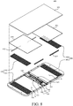
- FIG. 8 is a schematic exploded perspective view of a foldable display device according to another exemplary embodiment of the present disclosure.
- FIG. 9 is a perspective view of a foldable display device according to still another exemplary embodiment of the present disclosure.
- FIGs. 10A and 10B are perspective views for explaining a first holding unit according to still another exemplary embodiment of the present disclosure.
- a foldable display device 400 includes a first cover 110, a second cover 120, a first slide plate 415, a second slide plate 425, a hinge 130, a first holding unit 440, a second holding unit 450, and a display panel 160.
- a first cover 110 a second cover 120
- a first slide plate 415 a second slide plate 425
- a hinge 130 a hinge 130
- a first holding unit 440 a second holding unit 450
- a display panel 160 is omitted.
- the foldable display device 400 of FIGs. 8 and 9 may further include the first slide plate 415, the second slide plate 425, the first holding unit 440, and the second holding unit 450.
- the the holding members 133, 134, and 339 may be omitted from the hinge 130. That is, in the foregoing exemplary embodiments, the hinge 130 includes the holding members 133, 134, and 339 to implement the holding force of the foldable display devices 100 and 200.
- the holding force is implemented by the first holding unit 440 and the second holding unit 450. Therefore, the redundant description for the same configuration will be omitted below.
- the first cover 110 and the second cover 120 may be base members for supporting the display panel 160 and various components of the foldable display device 400. Further, each of the first cover 110 and the second cover 120 may include an accommodating unit S which accommodates various components for driving the foldable display device 400.
- the foldable display device 400 may maintain a specific folding angle by the holding force provided from the first holding unit 440 and the second holding unit 450 which will be described below.
- the first cover 110 and the second cover 120 may maintain a specific folding angle by the magnetic force of a permanent magnet which configures the first holding unit 440 and the second holding unit 450. Therefore, the foldable display device 400 is folded at a specific angle as intended by the user and maintains a folded state at the specific angle by the holding force of the first holding unit 440 and the second holding unit 450.
- the first slide plate 415 and the second slide plate 425 are disposed in the accommodating unit S of each of the first cover 110 and the second cover 120.
- the first slide plate 415 and the second slide plate 425 are plate-type slides and move back and forth in the accommodating unit S by a sliding operation. Further, the first slide plate 415 and the second slide plate 425 may be fixed to one side and the other side of the display panel 160.
- the first sliding plate 415 may slide by the folding of the display panel 160. Specifically, the first slide plate 415 may slide back and forth along a first direction perpendicular to a boundary line of the first cover 110 and the second cover 120.
- the first slide plate 415 may slide along the first direction to be far away from the boundary line or approach the boundary line.
- the first slide plate 415 may slide to be far away from the boundary line.
- the first slide plate 415 may slide to be closer to the boundary line.
- the second sliding plate 425 may slide by the folding of the display panel 160. Specifically, the second slide plate 425 may slide back and forth along the above-described first direction.
- the second slide plate 425 may slide along the first direction to be far away from the first cover 110 or approach the first cover 110.
- the second slide plate 425 may slide to be far away from the boundary line.
- the second slide plate 425 may slide to be closer to the boundary line.
- One side and the other side of the display panel 160 are fixed to the first slide plate 415 and the second slide plate 425 so that when the foldable display device 400 is folded, the sliding operation may be performed on one side and the other side of the display panel 160. That is, the one side and the other side of the display panel 160 may slide back and forth along the first direction by the folding of the foldable display device 400. Therefore, the damage of the display panel 160 caused by the folding of the foldable display device 400 may be avoided.
- the display panel 160 may also be folded to form a curved surface at a central portion of the foldable display device 400, that is, in the boundary area of the first cover 110 and the second cover 120. Therefore, when one side and the other side of the display panel 160 are fixed to the first cover 110 and the second cover 120 so as not to move, tension may be generated in a curved area of the display panel 160. Specifically, when the foldable display device 400 is out-folded, one side and the other side of the display panel 160 fixed to the first cover 110 and the second cover 120 are pulled in different directions by the first cover 110 and the second cover 120, so that the tension may be maximized. The tension may cause damage of the display panel 160, which may be a cause of failure of the foldable display device 400.
- one side and the other side of the display panel 160 are fixed to the first slide plate 415 and the second slide plate 425 so that when the foldable display device 400 is folded, one side and the other side of the display panel 160 may move together with the first slide plate 415 and the second slide plate 425. Therefore, the tension generated in the curved area of the display panel 160 is relaxed and the damage of the display panel 160 may be minimized.
- both the first slide plate 415 and the second slide plate 425 are disposed in both the first cover 110 and the second cover 120.
- any one of the first slide plate 415 and the second slide plate 425 may be omitted.
- the second slide plate 425 may be omitted.
- one side of the display panel 160 is fixed to the first slide plate 415 to move by folding the foldable display device 400 and the other side may be fixed to the second cover 120.
- the display panel 160 may be more stably folded as compared with the case that both sides of the display panel 160 move. Therefore, a damage of the foldable display device 400 may be further reduced.
- both sides of each of the first slide plate 415 and the second slide plate 425 are coupled to the pair of first slide rails 412 and the pair of second slide rails 422.
- the pair of first slide rails 412 and the pair of second slide rails 422 may be disposed in the accommodating unit of the first cover 110 and the second cover 120.
- the pair of first slide rails 412 may be spaced apart from each other to face each other and the pair of second slide rails 422 may be spaced apart from each other to face each other.
- the pair of first slide rails 412 and the pair of second slide rails 422 may be formed to extend in a direction parallel to the first direction. Therefore, the first slide plate 415 and the second slide plate 425 are coupled to the pair of first slide rails 412 and the pair of second slide rails 422 to move along the first direction.
- the pair of first slide rails 412 or the pair of second slide rails 422 corresponding thereto may be omitted.
- a pair of hinges 130 is provided to connect one side and the other side of the first fastening unit 111 and the second fastening unit 121.
- the hinge 130 is disposed in a portion where the foldable display device 100 is folded and unfolded to allow the foldable display device 100 to be easily folded and unfolded.
- the hinge 130 includes a hinge shaft 131, a rotating plate 132, and a fixing frame 137.
- the hinge shaft 131 may serve as a center axis to which components of the hinge 130 are coupled.
- a pair of hinge shafts 131 is provided to correspond to the first cover 110 and the second cover 120, respectively. That is, in one hinge 130, a pair of hinge shafts 131 corresponding to the first cover 110 and the second cover 120 may be provided.
- a pair of rotating plates 132 is provided to be coupled to one end of one pair of hinge shafts 131. Further, the pair of rotating plates 132 may correspond to the first cover 110 and the second cover 120, respectively. That is, the pair of rotating plates 132 may be fixed to the first fastening unit 111 of the first cover 110 and the second fastening unit 121 of the second cover 120. In this case, the pair of rotating plates 132 may be fixed to the first fastening unit 111 and the second fastening unit 121 by screw connection, but is not limited thereto. Further, when the foldable display device 400 is folded or unfolded, the pair of rotating plates 132 may rotate in accordance with the movement of the first cover 110 and the second cover 120.
- the fixing frame 137 is fixed to the other ends of the pair of hinge shafts 131. Further, the fixing frame 137 may include through holes through which the pair of hinge shafts 131 penetrates, at one side and the other side.
- the fixing frame 137 may serve to fix the components of the hinge 130. That is, the fixing frame 137 is disposed at the other ends of the pair of hinge shafts 131 to suppress the components fixed to the hinge shaft 131 from being left from the hinge shafts 131. Further, components such as a screw are provided at the outer side of the fixing frame 137 to be fastened with the hinge shafts 131 so that the fixing frame 137 and the pair of hinge shafts 131 may be more firmly coupled to each other.
- the first holding unit 440 and the second holding unit 450 are disposed in the accommodating units S of the first cover 110 and the second cover 120, respectively.
- the first holding unit 440 is disposed between an inner surface of the first cover 110 and the first slide plate 415.
- the second holding unit 450 is disposed between an inner surface of the second cover 120 and the second slide plate 425.
- the first holding unit 440 and the second holding unit 450 may provide a holding force for fixing the foldable display device 400 at a specific folding angle.
- the first holding unit 440 and the second holding unit 450 include permanent magnets to fix the first cover 110 and the second cover 120 at a specific folding angle by the magnetic force.
- both the first holding unit 440 and the second holding unit 450 are disposed on the first cover 110 and the second cover 120, when any one of the first slide plate 415 and the second slide plate 425 is omitted, the first holding unit 440 or the second holding unit 450 corresponding thereto may also be omitted.
- the first holding unit 440 and the second holding unit 450 have the same configuration except that the first holding unit 440 and the second holding unit 450 are disposed in the first cover 110 and the second cover 120, respectively. Therefore, hereinafter, the first holding unit 440 will be mainly described.
- the first holding unit 440 includes a first holding plate 441 and a second holding plate 442.
- the first holding plate 441 and the second holding plate 442 may be disposed to face each other and to be in contact with each other.
- the first holding plate 441 may be fixed to the first cover 110.
- the second holding plate 442 is fixed to the first slide plate 415 to slide together with the first slide plate 415. That is, when the display panel 160 is folded, the second holding plate 442 may slide together with the first slide plate 415.
- the second holding plate 442 may move along the pair of first slide rails 412 together with the first slide plate 415, but the present disclosure is not limited thereto.
- the first holding plate 441 and the second holding plate 442 may be formed of a magnetic substance.
- the first holding plate 441 and the second holding plate 442 includes a plurality of negative poles 441a and 442a and a plurality of positive poles 441b and 442b.
- the plurality of negative poles 441a and 442a and the plurality of positive poles 441b and 442b may be alternately disposed along a specific interval.
- the plurality of negative poles 441a and 442a and the plurality of positive poles 441b and 442b of the first holding plate 441 and the second holding plate 442 may be alternately disposed along a first direction perpendicular to the boundary line of the first cover 110 and the second cover 120.
- the first holding plate 441 including the plurality of negative poles 441a and the plurality of positive poles 441b and the second holding plate 442 including the plurality of negative poles 442a and the plurality of positive poles 442b are disposed to face each other so that magnetic force may be generated between the first holding plate 441 and the second holding plate 442. That is, the first holding plate 441 and the second holding plate 442 are disposed such that the plurality of negative poles 441a and 442 and the plurality of positive poles 441b and 442b face each other on a contact surface. Therefore, the first holding unit 440 may implement the holding force of the foldable display device 400 by the magnetic force between the first holding plate 441 and the second holding plate 442.
- the first cover 110 and the second cover 120 move to have a specific folding angle.
- the display panel 160 is also folded so that one side of the display panel 160 slides together with the first slide plate 415 and the second holding plate 442. Therefore, the plurality of negative poles 442a and the plurality of positive poles 442b of the second holding plate 442 may be disposed to alternately face the plurality of negative poles 441a and the plurality of positive poles 441b of the fixed first holding plate 441. Therefore, the first holding unit 440 may have a structure in which an attractive force or a repulsive force is repeated according to a specific angle formed by the first cover 110 and the second cover 120.
- an attractive force may be generated. That is, when the plurality of negative poles 441a of the first holding plate 441 and the plurality of positive poles 442b of the second holding plate 442 are disposed to face each other or the plurality of positive poles 441b of the first holding plate 441 and the plurality of negative poles 442a of the second holding plate 442 are disposed to face each other, the attractive force may be generated between the first holding plate 441 and the second holding plate 442.
- a repulsive force may be generated. That is, when the plurality of negative poles 441a of the first holding plate 441 and the plurality of negative poles 442a of the second holding plate 442 are disposed to face each other or the plurality of positive poles 441b of the first holding plate 441 and the plurality of positive poles 442b of the second holding plate 442 are disposed to face each other, the repulsive force may be generated between the first holding plate 441 and the second holding plate 442.
- the external force which is applied to the foldable display device 400 by the user may be larger than the attractive force and the repulsive force between the first holding plate 441 and the second holding plate 442. Therefore, even though the attractive force and the repulsive force are generated between the first holding plate 441 and the second holding plate 442, the user may fold or unfold the foldable display device 400 at a desired angle.
- the user may more easily perform the folding operation of the foldable display device 400 by a pushing force between magnets. That is, the repulsive force is generated in the first holding unit 440, the first holding plate 441 and the second holding plate 442 may be minutely spaced apart from each other by the repulsive force. In this case, the friction between the first holding plate 441 and the second holding plate 442 may be minimized. In other words, when the repulsive force is generated in the first holding unit 440, the friction between the first holding plate 441 and the second holding plate 442 may be minimized as compared with the case that the attractive force is generated in the first holding unit 440.
- the first holding plate 441 and the second holding plate 442 include the plurality of negative poles 441a and 442a and the plurality of positive poles 441b and 442b along a specific interval, so that a plurality of friction minimizing sections in which the friction is minimized may be provided. That is, the first holding plate 441 and the second holding plate 442 are disposed along a specific interval such that the same polarities face each other so that the friction between the first holding plate 441 and the second holding plate 442 may be minimized. In the friction minimizing section, the user may more easily perform the folding or unfolding operation of the foldable display device 400.
- the friction between the first holding plate 441 and the second holding plate 442 may be increased. That is, when the attractive force is generated in the first holding unit 440, the attractive force and the frictional force between the first holding plate 441 and the second holding plate 442 may be minimized as compared with the case that the repulsive force is generated in the holding unit.
- the holding force of the foldable display device 400 may be most strongly maintained in this section.
- the foldable display device 400 may maintain the specific folding angle by a magnetic force between the first holding plate 441 and the second holding plate 442.
- the first holding plate 441 and the second holding plate 442 are fixed to generate the holding force.
- the first holding plate 441 and the second holding plate 442 are fixed so that motions of the first cover 110, the first slide plate 415, and the display panel 160 fixed to the first holding plate 441 and the second holding plate 442 stop and thus the holding force may be generated.
- the repulsive force is generated in the first holding plate 441 and the second holding plate 442
- the first holding plate 441 and the second holding plate 442 may slide to generate the attractive force.
- the second holding plate 442 slides to be fixed to the first holding plate 441 so that the holding force may be generated thereby.
- the first holding plate 441 and the second holding plate 442 may be fixed to each other by the attractive force.
- the first holding plate 441 since the first holding plate 441 is fixed to the first cover 110, the movement of the first cover 110 may be suppressed by the attractive force of the first holding plate 441 and the second holding plate 442.
- the second holding plate 442 since the second holding plate 442 is fixed to the first slide plate 451 which is fixed to one side of the display panel 160, the sliding of the first slide plate 451 and the one side of the display panel 160 may be suppressed by the attractive force of the first holding plate 441 and the second holding plate 442.
- the foldable display device 400 may maintain a specific folding angle.
- the first holding plate 441 and the second holding plate 442 when the first holding plate 441 and the second holding plate 442 are disposed such that same polarities face each other, the first holding plate 441 and the second holding plate 442 may push each other by the repulsive force. Further, magnets have property that different polarities attract each other, so that the second holding plate 442 may slide to generate the attractive force with the first holding plate 441.
- the first holding plate 441 and the second holding plate 442 have a pattern in which the plurality of negative poles 441a and 442a and the plurality of positive poles 441b and 442b are alternately disposed, so that the attractive force may be generated between the first holding plate 441 and the second holding plate 442 only by a minute sliding operation of the second holding plate 442. As a result, the attractive force works between the first holding plate 441 and the second holding plate 442 so that the foldable display device 400 may maintain a specific folding angle.
- the foldable display device 400 may have various folding angles. That is, the first cover 110 and the second cover 120 may be fixed at angles corresponding to the plurality of negative poles 441a and 442a and the plurality of positive poles 441b and 442b. Therefore, the folding angle of the foldable display device 400 may be controlled by adjusting the number of the plurality of negative poles 441a and 442a and the plurality of positive poles 441b and 442b of the first holding plate 441 and the second holding plate 442 and intervals therebetween.
- the strength of the holding force of the foldable display device 400 may be controlled by adjusting the strength of the magnetic force of the permanent magnet applied to the first holding plate 441 and the second holding plate 442.
- the second holding unit 450 includes the first holding plate 451 and the second holding plate 452.
- the first holding plate 451 and the second holding plate 452 may be disposed to face each other and to be in contact with each other.
- the first holding plate 451 may be fixed to the second cover 120.
- the second holding plate 452 is fixed to the second slide plate 425 to slide together with the second slide plate 425. That is, when the display panel 160 slides, the second holding plate 452 may slide together with the second slide plate 425.
- the first holding plate 451 and the second holding plate 452 may have the same structure as the first holding plate 441 and the second holding plate 442 of the first holding unit 440. That is, the first holding plate 451 and the second holding plate 452 may include a plurality of negative poles and a plurality of positive poles which are alternately disposed along the first direction. Therefore, the holding force of the foldable display device 400 may be implemented by the magnetic force of the first holding plate 451 and the second holding plate 452.
- the second holding unit 450 may be omitted together with the second slide plate 425.
- the other side of the display panel 160 is fixed to the second cover 120 so as not to move and only one side of the display panel 160 may slide.
- the second slide plate 425 and the second holding unit 450 are provided and the first slide plate 415 and the first holding unit 440 may be omitted.
- the display panel 160 is disposed on the first cover 110 and the second cover 120. Specifically, one side and the other side of the display panel 160 are fixed to the first slide plate 415 and the second slide plate 425 to slide together with the first slide plate 415 and the second slide plate 425.
- the present disclosure is not limited thereto. That is, only one of the one side and the other side of the display panel 160 slides and the other one may be fixed.
- the display panel 160 may use any one of various display panels such as an organic light emitting display panel or a liquid crystal display panel. Further, the display panel 160 may have flexibility so as to be folded in accordance with the folding of the foldable display device 400.
- a general foldable display device implements a holding force for maintaining a specific folding angle of the foldable display device through a hinge. That is, the holding force is implemented by the frictional force between hinge components. However, the hinge components are worn out due to the frictional force caused by the consistent folding and unfolding operation, so that the holding force is decreased and the durability of the hinge and the foldable display device is lowered.
- the foldable display device 400 disposes the first holding unit 440 between the first cover 110 and the first slide plate 415 to implement the holding force through the first holding unit 440.
- the first holding unit 440 includes a first holding plate 441 fixed to the first cover 110 and a second holding plate 442 which is fixed to the first slide plate 415 and one side of the display panel 160 to slide.
- the first holding plate 441 and the second holding plate 442 include a plurality of negative poles 441a and 442a and a plurality of positive poles 441b and 442b, respectively.
- the first holding unit 440 may implement the holding force using a magnetic force between the first holding plate 441 and the second holding plate 442. Specifically, when the first holding plate 441 and the second holding plate 442 are disposed such that different polarities face each other to generate the attractive force therebetween, one side of the first cover 110, the first slide plate 415, and the display panel 160 which are fixed thereto by the attractive force may be fixed. Therefore, the foldable display device 400 may maintain a specific folding angle.
- the foldable display device 400 may implement the permanent holding force by the magnetic force between the permanent magnets. That is, even though the first holding plate 441 and the second holding plate 442 are in contact with each other to be worn out, the magnetic force may be consistently maintained. Therefore, the holding force of the first holding unit 440 may be permanently maintained. As a result, the decrease of the holding force is reduced so that the durability of the foldable display device 400 may be improved.
- the foldable display device 400 implements the holding force through the first holding unit 440 applied to the first slide plate 415, rather than through the hinge 130. Accordingly, the structure of the hinge 130 may be simplified as compared with the foregoing exemplary embodiments so that the manufacturing process of the foldable display device 400 is simplified and the manufacturing cost may be saved.
- FIG. 11 is a perspective view illustrating a first holding unit according to yet another exemplary embodiment of the present disclosure.
- the first holding unit 540 includes a first holding plate 541 and a second holding plate 542.
- the first holding plate 541 and the second holding plate 542 may be disposed to face each other and to be in contact with each other.
- the first holding plate 541 may be fixed to the first cover 110.
- the second holding plate 542 is fixed to the first slide plate 415 to slide together with the first slide plate 415. That is, when the display panel 160 is folded, the second holding plate 542 may slide together with the first slide plate 415.
- the first holding plate 541 and the second holding plate 542 include a plurality of negative poles 541a and 542a and a plurality of positive poles 541b and 542b.
- the plurality of negative poles 541a and 542a and the plurality of positive poles 541b and 542b of the first holding plate 541 and the second holding plate 542 may be alternately disposed such that the boundary lines of the plurality of negative poles 541a and 542a and the plurality of positive poles 541b and 542b are parallel to the first direction.
- a magnetic force may be generated between the first holding plate 541 including the plurality of negative poles 541a and the plurality of positive poles 541b and the second holding plate 542 including the plurality of negative poles 542a and the plurality of positive poles 542b. That is, the first holding plate 541 and the second holding plate 542 are disposed such that the plurality of negative poles 541a and 542a and the plurality of positive poles 541b and 542b face each other on a contact surface. Specifically, the first holding plate 541 and the second holding plate 542 may be disposed such that different polarities face each other. Therefore, the first holding unit 540 may implement the holding force of the foldable display device 400 by the attractive force between the first holding plate 541 and the second holding plate 542.
- the external force which is applied to the foldable display device 400 by the user may be larger than the attractive force between the first holding plate 541 and the second holding plate 542. Therefore, the user may fold the foldable display device 400 at a desired angle.
- the foldable display device 400 may maintain the specific folding angle by the attractive force between the first holding plate 541 and the second holding plate 542. That is, the first holding plate 541 and the second holding plate 542 are fixed by the attractive force and motions of the first cover 110, the first slide plate 415, and the display panel 160 fixed to the first holding plate 541 and the second holding plate 542 stop so that the holding force may be generated. Therefore, the foldable display device 400 may maintain a specific folding angle.
- the first holding unit 540 may implement the holding force of the foldable display device 400 only by the attractive force. Therefore, as compared with the case that the attractive force and the repulsive force alternately work in accordance with the sliding of the first slide plate 415, a precision of the operation of the first holding unit 540 may be improved.
- the first holding unit 540 reduces the number of the plurality of negative poles 541a and 542a and the plurality of positive poles 541b and 542b, so that the manufacturing process is simple and the manufacturing cost may be saved. That is, in the case of the first holding unit 440 illustrated in FIGs. 8 to 10B , the plurality of negative poles 441a and 442a and the plurality of positive poles 441b and 442b are alternately disposed along the first direction so that the attractive force and the repulsive force may be alternately generated when the foldable display device 400 is folded. Therefore, in order to provide various folding angles of the foldable display device 400, the first holding unit 440 needs to increase the number of the plurality of negative poles 441a and 442a and the plurality of positive poles 441b and 442b.
- the holding force may be implemented at all angles regardless of the number of plurality of negative poles 541a and 542a and the plurality of positive poles 541b and 542b.
- FIG. 12 is a perspective view illustrating a first holding unit according to yet another exemplary embodiment of the present disclosure.
- a first holding unit 640 includes a first holding plate 641 and a second holding plate 642.
- the first holding plate 641 and the second holding plate 642 may be disposed to face each other and to be in contact with each other.
- the first holding plate 641 may be fixed to the first cover 110.
- the second holding plate 642 is fixed to the first slide plate 415 to slide together with the first slide plate 415. That is, when the display panel 160 is folded, the second holding plate 642 may slide together with the first slide plate 415.
- the first holding plate 641 is formed of a metallic material.
- the second holding plate 642 is formed of a magnet to include a plurality of negative poles 642a and a plurality of positive poles 642b.
- the plurality of negative poles 642a and the plurality of positive poles 642b of the second holding plate 642 may be alternately disposed along the first direction. That is, the second holding plate 642 may be formed to be the same as the second holding plate 442 illustrated in FIGs. 10A and 10B .
- the second holding plate 642 is formed to be the same as the second holding plate 442 illustrated in FIGs. 10A and 10B
- the second holding plate 642 may be formed to be the same as the second holding plate 542 illustrated in FIG. 11 . That is, the plurality of negative poles 642a and the plurality of positive poles 642b of the second holding plate 642 may be alternately disposed such that the boundary line is parallel to the first direction.
- the first holding plate 641 is formed of a metallic material and the second holding plate 642 is formed of a magnet, but the opposite case is also possible. That is, the first holding plate 641 is formed of a magnet and the second holding plate 642 is formed of a metallic material.
- the first holding plate 641 is formed of a metal and the second holding plate 642 is formed of a magnet, so that the magnetic force may be generated between the first holding plate 641 and the second holding plate 642.
- the attractive force is generated between the first holding plate 642 and the second holding plate 642 so that the first holding unit 640 may implement the holding force of the foldable display device 400 by the attractive force.
- the external force which is applied to the foldable display device 400 by the user may be larger than the attractive force between the first holding plate 641 and the second holding plate 642. Therefore, the user may fold the foldable display device 400 at a desired angle.
- the foldable display device 400 may maintain the specific folding angle by an attractive force between the first holding plate 641 and the second holding plate 642. That is, the first holding plate 641 and the second holding plate 642 are fixed by the attractive force and motions of the first cover 110, the first slide plate 415, and the display panel 160 fixed to the first holding plate 641 and the second holding plate 642 stop so that the holding force may be generated. Therefore, the foldable display device 400 may maintain a specific folding angle.
- one of the first holding plate 641 and the second holding plate 642 is formed of a metallic material and the other one is formed of a magnet, so that the holding force may be implemented through the first holding unit 640 with a simpler structure. That is, the first holding unit 440 and 540 of the foregoing exemplary embodiments is configured by two magnets and each magnet includes a plurality of negative poles and a plurality of positive poles, but the first holding unit 640 according to another exemplary embodiment of the present disclosure includes only one magnet so that the first holding unit 640 may be more simply formed.
- the number of the plurality of negative poles 642a and the plurality of positive poles 642b may be reduced. That is, only the attractive force works in the first holding unit 640 so that the holding force may be implemented at all angles.
- FIGs. 13A to 14B an in-folding operation and an out-folding operation of a foldable display device according to still another exemplary embodiment of the present disclosure will be described with reference to FIGs. 13A to 14B .
- the first slide plate 415 and the first holding unit 440 are disposed in the first cover 110 of the foldable display device 400 and the second slide plate 425 and the second holding unit 450 in the second cover 120 are omitted.
- the present disclosure is not limited thereto.
- FIGs. 13A to 13C are schematic cross-sectional views for explaining an in-folding operation of a foldable display device according to yet another exemplary embodiment of the present disclosure.
- the foldable display device 400 may be in-folded so that the display panel 160 is disposed therein. At the time of in-folding, the foldable display device 400 may be folded such that one side and the other side of the display panel 160 face each other.
- the foldable display device 400 may be fully extended while the first cover 110 and the second cover 120 form approximately 180°.
- the display panel 160 disposed on the first cover 110 and the second cover 120 may be fully extended.
- two cases of the in-folding and out-folding will be described while defining the foldable display device 400 of FIG. 13A as an initial state.
- the first slide plate 415 disposed in the accommodating unit S of the first cover 110 may be spaced apart from the first inner surface 110a and a second inner surface 110b of the first cover 110.
- a distance spaced between the first slide plate 415 and the first inner surface 110a is defined as a first separation distance D1 and a distance spaced between the first slide plate 415 and the second inner surface 110b is defined as a second separation distance D2.
- first inner surface 110a and the second inner surface 110b may refer to surfaces which are parallel to the boundary line of the first cover 110 and the second cover 120, among inner surfaces which configure the accommodating unit S. Further, the first inner surface 110a may be adjacent to the boundary line of the first cover 110 and the second cover 120 and the second inner surface 110b may be spaced apart from the first inner surface 110a to face the first inner surface 110a.
- One side of the display panel 160 is fixed to the first slide plate 415 and the other side may be fixed to the second cover 120.
- the one side of the display panel 160 may slide by the sliding of the first slide plate 415.
- the other side of the display panel 160 is fixed to the second cover 120 so as not to slide.
- the other side of the display panel 160 may be fixed to the second cover 120 by a component such as a fixing member 123 disposed in the accommodating unit S of the second cover 120, but is not limited thereto.
- the foldable display device 400 may be in-folded by an external force to form approximately 90° by the first cover 110 and the second cover 120.
- the display panel 160 disposed on the first cover 110 and the second cover 120 may also be in-folded by the movement of the first cover 110 and the second cover 120. Further, the display panel 160 may be in-folded while bending the central portion corresponding to the boundary area of the first cover 110 and the second cover 120 in which the hinge 130 is disposed.
- the first sliding plate 415 may slide in a direction which is far away from the boundary line of the first cover 110 and the second cover 120.
- the direction which is far away from the boundary line of the first cover 110 and the second cover 120 may be a direction directed to the second inner surface 110b.
- the display panel 160 is curved inside the first cover 110 and the second cover 120, so that one end of the display panel 160 may be pushed toward the second inner surface 110b as compared with the initial state. That is, the central portion of the display panel 160 forms a curved surface in the first cover 110 and the second cover 120 so that as illustrated by an arrow in FIG. 13B , one side of the display panel 160 and the first slide plate 415 may slide toward the second inner surface 110b. Therefore, the first separation distance D1 may be increased and the second separation distance D2 may be decreased.
- the foldable display device 400 may be fixed while maintaining an in-folded angle by the holding force provided by the first holding unit 440.
- the first holding unit 440 includes the first holding plate 441 and the second holding plate 442 including a plurality of negative poles 441a and 442a and a plurality of positive poles 441b and 442b.
- the second holding plate 442 is fixed to the first slide plate 415 to slide together with the first slide plate 415. Therefore, the first holding plate 441 and the second holding plate 442 may be disposed such that different polarities face each other to generate the attractive force. That is, the folding angle of the foldable display device 400 may be maintained by the attractive force between the first holding plate 441 and the second holding plate 442.
- the foldable display device 400 may be in-folded by an external force so that the first cover 110 and the second cover 120 completely face each other.
- the first cover 110 and the second cover 120 may be disposed to completely face each other with the display panel 160 therebetween.
- the display panel 160 disposed on the first cover 110 and the second cover 120 may also be in-folded by the movement of the first cover 110 and the second cover 120 so that one side and the other side of the display panel 160 face each other.
- the display panel 160 may be in-folded while bending the central portion to form a curved surface.
- the central portion of the display panel 160 forms a curved surface in the first cover 110 and the second cover 120 so that as illustrated by an arrow in FIG. 13C , one side of the display panel 160 and the first slide plate 415 may slide toward the second inner surface 110b.
- the in-folding operation of the foldable display device 400 is larger than that of FIG. 13B , so that the first separation distance D1 may be further increased and the second separation distance D2 may be further decreased.
- an in-folding operation of the foldable display device 400 illustrated in FIG. 13C is larger than an in-folding operation of the foldable display device 400 illustrated in FIG. 13B .
- the first slide plate 415 may be closer to the second inner surface 110b. That is, as the in-folding operation of the foldable display device 400 is increased, the first separation distance D1 may be increased and the second separation distance D2 may be decreased.
- the first slide plate 415 may be in contact with the second inner surface 110b.
- the present disclosure is not limited thereto. Even though the foldable display device is fully in-folded in accordance with the design of the foldable display device 400, the first slide plate 415 and the second inner surface 110b may be spaced apart from each other.
- the foldable display device 400 may be fixed while maintaining an in-folded angle by the holding force provided by the first holding unit 440.
- FIGs. 14A and 14B are schematic cross-sectional views for explaining an out-folding operation of a foldable display device according to yet another exemplary embodiment of the present disclosure.
- the foldable display device 400 may be out-folded so that the display panel 160 is disposed thereoutside. That is, when the foldable display device is out-folded, the foldable display device 400 may be folded such that the first cover 110 and the second cover 120 face each other. In the meantime, the foldable display device 400 which has not been out-folded may have the same initial state as illustrated in FIG. 13A .
- the foldable display device 400 may be out-folded by an external force to form approximately 90° by the first cover 110 and the second cover 120.
- the display panel 160 disposed on the first cover 110 and the second cover 120 may also be out-folded by the movement of the first cover 110 and the second cover 120.
- the display panel 160 may be out-folded while the central portion is bent to form a curved surface.
- the first sliding plate 415 may slide in a direction which is closer to the boundary line of the first cover 110 and the second cover 120.
- the direction which is closer to the boundary line of the first cover 110 and the second cover 120 may be a direction directed to the first inner surface 110a.
- the display panel 160 is curved outside the first cover 110 and the second cover 120, so that one end of the display panel 160 may be pulled toward the first inner surface 110a as compared with the initial state. That is, the central portion of the display panel 160 forms a curved surface outside the first cover 110 and the second cover 120 so that as illustrated by an arrow in FIG. 14A , one side of the display panel 160 and the first slide plate 415 may slide toward the first inner surface 110a. Therefore, the first separation distance D1 may be decreased and the second separation distance D2 may be increased.
- the foldable display device 400 may be fixed while maintaining an out-folded angle by the holding force provided by the first holding unit 440.
- the foldable display device 400 may be out-folded by an external force so that the first cover 110 and the second cover 120 completely face each other.
- the display panel 160 disposed on the first cover 110 and the second cover 120 may also be out-folded by the movement of the first cover 110 and the second cover 120 such that one side and the other side of the display panel 160 face each other.
- one side and the other side of the display panel 160 may be out-folded to face each other with the first cover 110 and the second cover 120 therebetween.
- the display panel 160 may be out-folded while the central portion is bent to form a curved surface.
- the central portion of the display panel 160 forms a curved surface outside the first cover 110 and the second cover 120 so that as illustrated by an arrow in FIG. 14B , one side of the display panel 160 and the first slide plate 415 may slide toward the first inner surface 110a.
- the out-folding operation of the foldable display device 400 is larger than that of FIG. 14A , so that the first separation distance D1 may be further decreased and the second separation distance D2 may be further increased.
- an out-folding operation of the foldable display device 400 illustrated in FIG. 14B is larger than an out-folding operation of the foldable display device 400 illustrated in FIG. 14A .
- the first slide plate 415 may be closer to the first inner surface 110a. That is, as the out-folding operation of the foldable display device 400 is increased, the first separation distance D1 may be decreased and the second separation distance D2 may be increased.
- the first slide plate 415 may be in contact with the first inner surface 110a.
- the present disclosure is not limited thereto. Even though the foldable display device is fully out-folded in accordance with the design of the foldable display device 400, the first slide plate 415 and the first inner surface 110a may be spaced apart from each other.
- the foldable display device 400 may be fixed while maintaining an out-folded angle by the holding force provided by the first holding unit 440.
- the first slide plate 415 and the first holding unit 440 are disposed in the first cover 110, but the second slide plate 425 and the second holding unit 450 may be omitted.
- the second slide plate 425 and the second holding unit 450 are disposed in the second cover 120 and the first slide plate 415 and the first holding unit 440 may be omitted.
- first slide plate 415 and the first holding unit 440 and the second slide plate 425 and the second holding unit 450 may be disposed on both the first cover 110 and the second cover.
- one side and the other side of the display panel 160 may slide together with the first slide plate 415 and the second slide plate 425.
- the one side and the other side corresponding to the first cover 110 and the second cover 120 of the foldable display device 400 may be balanced. Specifically, positions of one end and the other end of the display panel 160 may be symmetrical.
- the first separation distance D1 or the second separation distance D2 which is an interval for sliding is necessary for the first cover 110 on which the first slide plate 415. Therefore, as illustrated in FIG. 13A , one end of the display panel 160 is disposed to be spaced apart from the end of the first cover 110 and the other end is disposed to be adjacent to the end of the second cover 110. Further, as illustrated in FIG. 14B , when the foldable display device 400 is fully out-folded, one end and the other end of the display panel 160 may not be disposed on the same line.
- the one end and the other end of the display panel 160 may be disposed to be symmetrical.
- the foldable display device 400 may be configured to be in-folded and out-folded. That is, in the initial state of the foldable display device 400, the first slide plate 415 may be spaced apart from the first inner surface 110a and the second inner surface 110b with the first separation distance D1 and the second separation distance D2. Therefore, at the time of in-folding, the first slide plate 415 may slide toward the second inner surface 110b so that the second separation distance D2 is decreased. Further, at the time of out-folding, the first slide plate 415 may slide toward the first inner surface 110a so that the first separation distance D1 is decreased.
- the foldable display device 400 is configured to be in-folded and out-folded, various folding operations may be performed so that convenience of the user may be increased.
- the foldable display device 400 may be configured to perform only the in-folding operation.
- the foldable display device 400 may be configured such that the first separation distance D1 for out-folding may be omitted in an initial state. That is, in the initial state, the first slide plate 415 may be in contact with the first inner surface 110a.
- the foldable display device 400 may be configured to perform only the out-folding operation.
- the foldable display device 400 may be configured such that the second separation distance D2 for in-folding may be omitted in an initial state. That is, in the initial state, the first slide plate 415 may be in contact with the second inner surface 110b.
- the first separation distance D1 or the second separation distance D2 is omitted so that the size of the foldable display device 400 may be reduced.
- a foldable display device includes a display panel disposed on a first cover and a second cover; and at least one hinge which connects the first cover and the second cove and the hinge includes a fixing frame, a pair of hinge shafts which passes through the fixing frame; a pair of rotating plates which is fixed to one end of the pair of hinge shafts and fixed to the first cover and the second cover to rotate together with the first cover and the second cover; and a pair of first holding members which is coupled to the pair of hinge shafts between the fixing frame and the pair of rotating plates and controls a folding angle of the first cover and the second cover by a magnetic force.
- the pair of first holding members may rotate together with the pair of rotating plates.
- the foldable display device may further include a pair of second holding members which is fixed to the fixing frame and is fixed to the pair of hinge shafts between the fixing frame and the pair of first holding members.
- each of the pair of first holding members and each of the pair of second holding members may include a plurality of negative poles and a plurality of positive poles and the plurality of negative poles and the plurality of positive poles may be alternately disposed along a direction perpendicular to the hinge shaft.
- the pair of rotating plates when the pair of first holding members and the pair of second holding members are disposed such that different polarities face each other by the rotation of the pair of first holding members, the pair of rotating plates may be fixed.
- the pair of rotating plates may be fixed by an attractive force between the pair of first holding members and the fixing frame.
- the foldable display device may further include a fixing plate which is spaced apart from the fixing frame to be fixed to the other end of the pair of hinge shafts; and a pair of springs which is coupled to the pair of hinge shafts between the fixing plate and the fixing frame to provide a surface friction force to the pair of first holding members by an elastic force.
- the pair of first holding members may be fixed to the fixing frame and a pair of third holding members which is fixed to the first cover and the second cover, respectively and is disposed to be adjacent to the pair of first holding members to move together with the first cover and the second cover may be further provided.
- the pair of first holding members may include a plurality of negative poles and a plurality of positive poles and the plurality of negative poles and the plurality of positive poles may be alternately disposed along a direction perpendicular to the hinge shaft and the pair of third holding members may include at least one of negative poles and positive poles in an area facing the pair of first holding members.
- the first cover and the second cover may be fixed.
- a foldable display device in another aspect of the present disclosure, includes: a first cover and a second cover coupled to the first cover; a display panel disposed on the first cover and the second cover; a first slide plate which is fixed to one side of the display panel and is disposed in the first cover to slide along a first direction perpendicular to a boundary line of the first cover and the second cover by the folding of the display panel; and a first holding unit which is disposed between the first cover and the first slide plate to control a folding angle of the first cover and the second cover by a magnetic force.
- the first holding unit may include: a first holding plate fixed to the first cover; and a second holding plate which is fixed to the first slide plate to slide together with the first slide plate.
- first holding plate and the second holding plate may be disposed to be in contact with each other.
- each of the first holding plate and the second holding plate may include a plurality of negative poles and a plurality of positive poles which are alternately disposed along the first direction, and when the first holding plate and the second holding plate are disposed such that different polarities face each other, the first cover may be fixed to form a specific folding angle with the second cover.
- the plurality of negative poles and the plurality of positive poles of the first holding plate and the second holding plate may be alternately disposed and the boundary line of the plurality of negative poles and the positive poles may be parallel to the first direction and the first holding plate and the second holding plate may be disposed such that different polarities face each other.
- one of the first holding plate and the second holding plate may be formed of a metallic material and the other one may be configured by a magnet.
- the other side of the display panel may be fixed to the second cover.
- the foldable display device may further include: a second slide plate which is fixed to the other side of the display panel and disposed in the second cover to slide along the first direction by the folding of the display panel; and a second holding unit which is disposed between the second cover and the second slide plate to control a folding angle of the first cover and the second cover by a magnetic force.
- the second holding unit may include a first holding plate fixed to the second cover; and a second holding plate which is fixed to the second slide plate to slide together with the second slide plate.
- the first slide plate when the display panel is in-folded to be disposed inside of the first cover and the second cover, the first slide plate may slide in a direction to be far away from the boundary line of the first cover and the second cover, and when the display panel is out-folded to be disposed outside of the first cover and the second cover, the first slide plate may slide in a direction to be closer to the boundary line of the first cover and the second cover.
- a frame device includes: a first supporting unit and a second supporting unit; a hinge which connects the first supporting unit and the second supporting unit; and a holding unit which includes a plurality of magnetic substances disposed in at least any one of the first supporting unit, the second supporting unit, and the hinge to allow the first supporting unit and the second supporting unit to maintain a specific angle, in which an attractive force and a repulsive force of the plurality of magnetic substances are repeated according to the specific angle formed by the first supporting unit and the second supporting unit.
- the hinge may include a rotation center axis, the plurality of magnetic substances may be disposed in the hinge such that negative poles and positive poles are alternately disposed along a specific interval to surround the rotation center axis, and the plurality of magnetic substances may be disposed to correspond to each other.
- At least one of the first supporting unit and the second supporting unit may further include a plate-type slide
- the plurality of magnetic substances may include a first magnetic substance fixed to at least one of the first supporting unit and the second supporting unit and a second magnetic substance which is fixed to the plate-type slide to correspond to the first magnetic substance, and the negative poles and the positive poles of the first magnetic substance and the second magnetic substance may be alternately disposed along a specific interval.
- a plurality of friction minimizing sections where the friction between the plurality of magnetic substances is minimized may be provided at the specific angle formed by the first supporting unit and the second supporting unit.
Landscapes
- Engineering & Computer Science (AREA)
- Theoretical Computer Science (AREA)
- Computer Hardware Design (AREA)
- Physics & Mathematics (AREA)
- General Physics & Mathematics (AREA)
- Human Computer Interaction (AREA)
- General Engineering & Computer Science (AREA)
- Microelectronics & Electronic Packaging (AREA)
- Mechanical Engineering (AREA)
- Mathematical Physics (AREA)
- Devices For Indicating Variable Information By Combining Individual Elements (AREA)
Abstract
Description
- This application claims the priority of Korean Patent Application No.
10-2017-0181107, filed December 27, 2017 10-2017-0180930 filed December 27, 2017 - The present disclosure relates to a foldable display device, and more particularly, to a foldable display device that permanently implements a holding force.
- Recently, mobile terminals such as a wireless terminal, a personal digital assistant (PDA), a portable multimedia player (PMP), or an electronic notebook are being small-sized to ensure portability. However, since a user wants to receive various information, such as character information, videos, still images, MP3, or games through a screen of the portable terminal, the user requires a large-sized or a wide-sized screen for the display unit. However, the reduction of the portable terminal results in reduction in the size of the screen of the display unit, so that there are limitations for satisfying both requirements.
- To overcome the above-mentioned limitations, recently, a flexible display device such as a bendable display device or a foldable display device is being developed.
- The flexible display device may be implemented by configuring a substrate with a plastic material. When the flexible display device is folded, it is simply carried and when the flexible display device is unfolded, a large screen is implemented so that the flexible display device may be applied to various fields including not only mobile equipment such as a mobile phone, an electronic book, or electronic newspaper, but also a television or a monitor.
- The inventors of the present disclosure invented a structure which uses equipment with a hinge in an area where the display panel is folded to implement a foldable display device. That is, in order to maintain a specific folding angle of the foldable display device when the foldable display is folded and unfolded, the inventors of the present disclosure implement a holding force using a frictional force between components which configure the hinge. However, the inventors of the present disclosure recognized that due to the repeated or consistent folding and unfolding operation of the foldable display device, the components which configure the hinge are worn out to decrease the holding force for maintaining the specific folding angle of the foldable display device.
- Therefore, the inventors of the present disclosure invented a foldable display device with a new structure which provides the holding force permanently without decreasing the holding force even though the foldable display device is consistently used.
- Accordingly, embodiments of the present disclosure are directed to a foldable display device that substantially obviates one or more of the problems due to limitations and disadvantages of the related art.
- An aspect of the present disclosure is to provide a foldable display device which provides a holding force for maintaining a folding angle of the foldable display device through a hinge including a holding member using a permanent magnet.
- Another aspect of the present disclosure is to provide a foldable display device which provides a holding force for maintaining a folding angle of the foldable display device by disposing a holding unit which uses a permanent magnet on a slide plate.
- Still another aspect of the present disclosure is to provide a foldable display device which improves durability by permanently providing the holding force by a magnetic force.
- Still another aspect of the present disclosure is to provide a foldable display device which may reduce a manufacturing cost by means of a simple hinge structure.
- Additional features and aspects will be set forth in the description that follows, and in part will be apparent from the description, or may be learned by practice of the inventive concepts provided herein. Other features and aspects of the inventive concepts may be realized and attained by the structure particularly pointed out in the written description, or derivable therefrom, and the claims hereof as well as the appended drawings.
- To achieve these and other aspects of the inventive concepts, as embodied and broadly described, a foldable display device comprises a display panel disposed on a first cover and a second cover; and at least one hinge which connects the first cover and the second cover and the hinge includes a fixing frame, a pair of hinge shafts which passes through the fixing frame; a pair of rotating plates which is fixed to one end of the pair of hinge shafts and fixed to the first cover and the second cover to rotate together with the first cover and the second cover; and a pair of first holding members which is coupled to the pair of hinge shafts between the fixing frame and the pair of rotating plates and controls a folding angle of the first cover and the second cover by a magnetic force.
- According to another aspect of the present disclosure, a foldable display device comprises a first cover and a second cover coupled to the first cover; a display panel disposed on the first cover and the second cover; a first slide plate which is fixed to one side of the display panel and is disposed in the first cover to slide along a first direction perpendicular to a boundary line of the first cover and the second cover by the folding of the display panel; and a first holding unit which is disposed between the first cover and the first slide plate to control a folding angle of the first cover and the second cover by a magnetic force.
- According to still another aspect of the present disclosure, a frame device comprises a first supporting unit and a second supporting unit; a hinge which connects the first supporting unit and the second supporting unit; and a holding unit which includes a plurality of magnetic substances disposed in at least any one of the first supporting unit, the second supporting unit, and the hinge to allow the first supporting unit and the second supporting unit to maintain a specific angle, in which an attractive force and a repulsive force of the plurality of magnetic substances are repeated according to the specific angle formed by the first supporting unit and the second supporting unit.
- Therefore, the holding force of the foldable display device may be permanently provided.
- According to the present disclosure, the holding member of the hinge is configured using a permanent magnet so that the holding force for maintaining a specific folding angle of the foldable display device may be implemented.
- According to the present disclosure, the holding unit is configured using a permanent magnet and is applied to the slide plate so that the holding force for maintaining a specific folding angle of the foldable display device may be implemented.
- According to the present disclosure, a magnetic force of the permanent magnet is used to provide the permanent holding force so that the durability of the foldable display device may be improved.
- According to the present disclosure, a simple hinge structure is implemented by means of a hinge or a holding unit using a permanent magnet, so that the manufacturing cost of the foldable display device may be reduced.
- It is to be understood that both the foregoing general description and the following detailed description are exemplary and explanatory and are intended to provide further explanation of the inventive concepts as claimed.
- The accompanying drawings, which are included to provide a further understanding of the disclosure and are incorporated and constitute a part of this application, illustrate embodiments of the disclosure and together with the description serve to explain various principles. In the drawings:
-
FIG. 1 is a schematic exploded perspective view of a foldable display device according to an exemplary embodiment of the present disclosure; -
FIG. 2 is a plan view of a foldable display device according to an exemplary embodiment of the present disclosure; -
FIG. 3 is an enlarged view of a region A ofFIG. 2 ; -
FIGs. 4A and 4B are an enlarged view and a cross-sectional view of a hinge of a foldable display device according to an exemplary embodiment of the present disclosure; -
FIGs. 5A, 5B are perspective views for explaining a first and a second holding member of a foldable display device according to an exemplary embodiment of the present disclosure; -
FIG. 6A is a plan view of a foldable display device according to another exemplary embodiment of the present disclosure; -
FIG. 6B is an enlarged view of a region B ofFIG. 6A ; -
FIG. 7A is a perspective view of a foldable display device according to still another exemplary embodiment of the present disclosure; -
FIG. 7B is an enlarged view of a region C ofFIG. 7A ; -
FIG. 8 is a schematic exploded perspective view of a foldable display device according to another exemplary embodiment of the present disclosure; -
FIG. 9 is a perspective view of a foldable display device according to still another exemplary embodiment of the present disclosure; -
FIGs. 10A and 10B are perspective views for explaining a first holding unit according to still another exemplary embodiment of the present disclosure; -
FIG. 11 is a perspective view illustrating a first holding unit according to yet another exemplary embodiment of the present disclosure; -
FIG. 12 is a perspective view illustrating a first holding unit according to yet another exemplary embodiment of the present disclosure; -
FIGs. 13A to 13C are schematic cross-sectional views for explaining an in-folding operation of a foldable display device according to yet another exemplary embodiment of the present disclosure; -
FIGs. 14A and14B are schematic cross-sectional views for explaining an out-folding operation of a foldable display device according to yet another exemplary embodiment of the present disclosure. - Advantages and characteristics of the present disclosure and a method of achieving the advantages and characteristics will be clear by referring to exemplary embodiments described below in detail together with the accompanying drawings. However, the present disclosure is not limited to the exemplary embodiment disclosed herein but will be implemented in various forms. The exemplary embodiments are provided by way of example only so that a person of ordinary skilled in the art can fully understand the disclosures of the present disclosure and the scope of the present disclosure. Therefore, the present disclosure will be defined only by the scope of the appended claims. The shapes, sizes, ratios, angles, numbers, and the like illustrated in the accompanying drawings for describing the exemplary embodiments of the present disclosure are merely examples, and the present disclosure is not limited thereto. Further, in the following description, a detailed explanation of known related technologies may be omitted to avoid unnecessarily obscuring the subject matter of the present disclosure. The terms such as "including," "having," and "consist of' used herein are generally intended to allow other components to be added unless the terms are used with the term "only". Any references to singular may include plural unless expressly stated otherwise. Components are interpreted to include an ordinary error range even if not expressly stated. When the position relation between two parts is described using the terms such as "on", "above", "below", and "next", one or more parts may be positioned between the two parts unless the terms are used with the term "immediately" or "directly". When an element or layer is disposed "on" another element or layer, it means that another layer or another element may be disposed directly on the other element or a third part may be interposed therebetween. Although the terms "first", "second", and the like are used for describing various components, these components are not confined by these terms. These terms are merely used for distinguishing one component from the other components. Therefore, a first component to be mentioned below may be a second component in a technical concept of the present disclosure. Like reference numerals generally denote like elements throughout the specification. A size and a thickness of each component illustrated in the drawing are illustrated for the convenience of description, and the present disclosure is not limited to the size and the thickness of the component illustrated. The features of various embodiments of the present disclosure can be partially or entirely bonded to or combined with each other and can be interlocked and operated in technically various ways understood by those skilled in the art, and the embodiments can be carried out independently of or in association with each other.
- Hereinafter, various exemplary embodiments of the present disclosure will be described in detail with reference to accompanying drawings.
-
FIG. 1 is a schematic exploded perspective view of a foldable display device according to an exemplary embodiment of the present disclosure.FIG. 2 is a plan view of a foldable display device according to an exemplary embodiment of the present disclosure. - Referring to
FIGs. 1 and2 , afoldable display device 100 according to an exemplary embodiment of the present disclosure includes afirst cover 110, asecond cover 120, ahinge 130, and adisplay panel 160. InFIG. 1 , even though components of thefoldable display device 100 are briefly illustrated for the convenience of description, actually, various components for driving thefoldable display device 100 may be further included. Further, inFIG. 2 , for the convenience of description, thedisplay panel 160 is omitted. - The
first cover 110 and thesecond cover 120 may serve as supporting units. That is, thefirst cover 110 and thesecond cover 120 may be base members for supporting thedisplay panel 160 and various components of thefoldable display device 100. Further, thefirst cover 110 and thesecond cover 120 may include an accommodating unit S which accommodates various components for driving thefoldable display device 100. - As described below in more detail with reference to
FIG. 8 , in the accommodating unit S, components such as afirst slide plate 415, asecond slide plate 425, afirst holding unit 440, and a second holding unit 450 are further disposed. - The
first cover 110 and thesecond cover 120 may be disposed in one area and the other area where thefoldable display device 100 is folded and unfolded. That is, thefoldable display device 100 is folded or unfolded with respect to a boundary area of thefirst cover 110 and thesecond cover 120 by an external force which is applied by a user to perform a folding operation. Further, thefirst cover 110 and thesecond cover 120 may correspond to one area and the other area of thedisplay panel 160 which will be described below. Therefore, thedisplay panel 160 may also be folded with respect to a boundary line of thefirst cover 110 and thesecond cover 120 by folding thefoldable display device 100. - The
first cover 110 and thesecond cover 120 include afirst fastening unit 111 and asecond fastening unit 121 which are coupled to thehinge 130, respectively. Thefirst cover 110 and thesecond cover 120 may have the same shape and thefirst fastening unit 111 and thesecond fastening unit 121 may be symmetrically disposed to face each other. - The
hinge 130 connects thefirst fastening unit 111 of thefirst cover 110 and thesecond fastening unit 121 of thesecond cover 120. In this case, one ormore hinges 130 may be provided if necessary. InFIGs. 1 and2 , although hinges are provided on one side and the other side of thefirst fastening unit 111 and thesecond fastening unit 121, this is just an example for description of the present disclosure and the present disclosure is not limited thereto. - Specifically, a pair of
hinges 130 may connect one side and the other side of thefirst fastening unit 111 and thesecond fastening unit 121, respectively. Thehinge 130 is disposed in a portion where thefoldable display device 100 is folded and unfolded to allow thefoldable display device 100 to be easily folded and unfolded. Further, thehinge 130 may provide a holding force to maintain a folded state of thefoldable display device 100 at a specific angle. In this case, the holding force of thehinge 130 may be provided from the magnetic force by a permanent magnet. A specific structure and function of thehinge 130 will be described below with reference toFIGs. 3-6B . - The
display panel 160 is disposed on one surfaces of thefirst cover 110 and thesecond cover 120. Thedisplay panel 160 may use any one of various display panels such as an organic light emitting display panel or a liquid crystal display panel. Further, thedisplay panel 160 may have flexibility so as to be folded and unfolded in accordance with the folding and unfolding of thefoldable display device 100. - The
foldable display device 100 may be folded so that thefirst cover 110 and thesecond cover 120 form a specific folding angle. That is, although inFIGs. 1 and2 , thefirst cover 110 and thesecond cover 120 are completely unfolded to at 180 degrees, thefoldable display device 100 may be folded at a specific angle. In this case, thedisplay panel 160 disposed on thefirst cover 110 and thesecond cover 120 is also folded in accordance with the folding of thefirst cover 110 and thesecond cover 120. - That is, the
foldable display device 100 may be folded at a specific angle as intended by the user. Further, thefoldable display device 100 may be fully folded or unfolded as intended by the user. Moreover, thefoldable display device 100 may be in-folded so that thedisplay panel 160 is folded or unfolded to be disposed therein or may be out-folded so that thedisplay panel 160 is folded or unfolded to be disposed outside therefrom. The in-folding and out-folding of thefoldable display device 100 will be described below in more detail with respect toFIGs. 13A to 14B . - The
foldable display device 100 may maintain a specific folding angle by the holding force provided by thehinge 130. In other words, thefirst cover 110 and thesecond cover 120 may be fixed while maintaining a specific folding angle by thehinge 130. Therefore, thefoldable display device 100 is folded at a specific angle as intended by the user and maintains a folded state at the specific angle by the holding force of the hinge. - Hereinafter, a specific configuration of the hinge is described with reference to
FIGs. 3 to 6B . -
FIG. 3 is an enlarged view of a region A ofFIG. 2 .FIGs. 4A and 4B are an enlarged view and a cross-sectional view of a hinge of a foldable display device according to an exemplary embodiment of the present disclosure.FIGs. 5A and 5B are perspective views for explaining a first holding member and a second holding member of a foldable display device according to an exemplary embodiment of the present disclosure. - Referring to
FIGs. 3 to 5B , thehinge 130 according to an exemplary embodiment of the present disclosure includes ahinge shaft 131, arotating plate 132, a first holdingmember 133, asecond holding member 134, a fixingframe 135, aspring 136, and a fixingplate 137. - The
hinge shaft 131 may serve as a center axis to which components of thehinge 130 are coupled. A pair ofhinge shafts 131 is provided to correspond to thefirst cover 110 and thesecond cover 120, respectively. That is, when thefirst cover 110 and thesecond cover 120 move, thehinge shaft 131 serves as a rotational center axis of the components coupled to thehinge shaft 131. - A pair of
rotating plates 132 is provided to be coupled to one ends of one pair ofhinge shafts 131. Further, the pair ofrotating plates 132 may correspond to thefirst cover 110 and thesecond cover 120, respectively. That is, the pair ofrotating plates 132 includes a plurality offastening grooves 132a to be fixed to thefirst fastening unit 111 of thefirst cover 110 and thesecond fastening unit 121 of thesecond cover 120. In this case, the pair ofrotating plates 132 may be fixed to thefirst fastening unit 111 and thesecond fastening unit 121 by screw connection, but is not limited thereto. Further, when the foldable display device100 is folded or unfolded, the pair ofrotating plates 132 may rotate with the movement of thefirst cover 110 and thesecond cover 120. - One pair of first holding
members 133 is provided to be coupled to one pair ofhinge shafts 131, respectively. Specifically, the pair of first holdingmembers 133 is coupled to an area of thehinge shaft 131 which is adjacent to the pair ofrotating plates 132. Further, the pair of first holdingmembers 133 may be fixed to one pair ofrotating plates 132 to rotate together with the pair ofrotating plates 132. That is, when thefoldable display device 100 is folded or unfolded, the pair of first holdingmembers 133 may rotate together with the pair ofrotating plates 132 in accordance with the movement of thefirst cover 110 and thesecond cover 120. - The pair of first holding
members 133 may be formed of a magnetic substance. Specifically, the pair of first holdingmembers 133 may be cylindrical magnets including through holes through which thehinge shafts 131 penetrate. That is, the pair of first holdingmembers 133 may be a cylindrical magnet including an upper surface and a lower surface on which openings corresponding to the through holes are disposed and an outer surface and an inner surface which connect the upper surface and the lower surface. The upper surface and the lower surface face each other. In this case, the inner surfaces of the pair of first holdingmembers 133 may correspond to a periphery of thehinge shaft 131. - The pair of first holding
members 133 includes a plurality ofnegative poles 133a and a plurality ofpositive poles 133b. The plurality ofnegative poles 133a and the plurality ofpositive poles 133b may be alternately disposed. Preferably, the plurality ofnegative poles 133a and the plurality ofpositive poles 133b are disposed along a direction perpendicular to thehinge shaft 131. Further, the plurality ofnegative poles 133a and the plurality ofpositive poles 133b may be alternately disposed along a specific interval to surround thehinge shaft 131. That is, the plurality ofnegative poles 133a and the plurality ofpositive poles 133b may be alternately disposed to surround a circumference of thehinge shaft 131 along a circumferential direction of thehinge shaft 131. Therefore, the pair of first holdingmembers 133 may be cylindrical magnets configured by the plurality ofnegative poles 133a and the plurality ofpositive poles 133b which are alternately disposed along the circumferential direction of the pair ofhinge shafts 131. - In this case, on the outer surface of the pair of first holding
members 133, a length of a boundary line between one of the plurality ofnegative poles 133a and one of the plurality ofpositive poles 133b may be equal to a length between the upper surface and the lower surface of the pair of first holdingmembers 133. Furthermore, a sum of the intervals or widths of the plurality ofnegative poles 133a and the plurality ofpositive poles 133b may be equal to a circumferential length of the pair of first holdingmembers 133 which are perpendicular to a length between the upper surface and the lower surface of the pair of first holdingmembers 133. - In the meantime, the upper surface or the lower surface of the pair of first holding
members 133 may be in contact with the upper surface or the lower surface of the pair of second holdingmembers 134 which will be described below. In this case, on the upper surfaces or lower surfaces of the pair of first holdingmembers 133, the plurality ofnegative poles 133a and the plurality ofpositive poles 133b may be alternately disposed along the circumference of the opening. - One pair of second holding
members 134 is provided to be coupled to one pair ofhinge shafts 131, respectively. Specifically, one pair of second holdingmembers 134 is coupled to the pair of first holdingmembers 133 to face each other in an area adjacent to the pair of first holdingmembers 133. In this case, the pair of second holdingmembers 134 may be fixed to the fixingframe 135 which will be described below. That is, even though thefoldable display device 100 is folded or unfolded, the pair of second holding members134 is fixed to the fixingframe 135 so as not to rotate. - The pair of second holding
members 134 may have the same shape as the pair of first holdingmembers 133. That is, the pair of second holdingmember 134 may be formed of a magnetic substance. Specifically, the pair of second holdingmembers 134 may be cylindrical magnets including through holes through which thehinge shafts 131 penetrate. Further, the pair of second holdingmembers 134 may be a cylindrical magnet in which a multiplenegative poles 134a and a multiplepositive poles 134b are alternately disposed along a direction perpendicular to thehinge shaft 131. - The upper surface or the lower surface of the pair of second holding
members 134 may be in contact with the upper surface or the lower surface of the pair of first holdingmembers 133. In this case, on the upper surfaces or lower surfaces of the pair of second holdingmembers 134, the plurality ofnegative poles 134a and the plurality ofpositive poles 134b may be alternately disposed along the circumference of the opening. - That is, the pair of first holding
members 133 and the pair of second holdingmembers 134 are disposed such that the upper surfaces and the lower surfaces are in contact with each other while facing each other. In this case, on contact surfaces of the pair of first holdingmembers 133 and the pair of second holdingmembers 134, the plurality ofnegative poles positive poles members 133 and the pair of second holdingmembers 134, magnetic forces may be generated by the plurality ofnegative poles positive poles - The pair of first holding
members 133 and the pair of second holdingmembers 134 may serve as holding units for implementing the holding force of thehinge 130. That is, the pair of holding units may implement a holding force so that thefirst cover 110 and thesecond cover 120 maintain a specific angle by the magnetic force. Specifically, as illustrated inFIG. 5A , when the first holdingmember 133 and the second holdingmember 134 are disposed such that different polarities face each other, an attractive force may be generated. In contrast, as illustrated inFIG. 5B , when the first holdingmember 133 and the second holdingmember 134 are disposed such that same polarities face each other, a repulsive force may be generated. - To be more specific, when the user applies a force to fold or unfold the
foldable display device 100, the pair of first holdingmembers 133 fixed to the pair ofrotating plates 132 may rotate by the movement of thefirst cover 110 and thesecond cover 120. In this case, the pair of second holdingmembers 134 may be fixed to the fixingframe 135 so as not to rotate. Therefore, the plurality ofnegative poles 134a and the plurality ofpositive poles 134b of the pair of fixed second holdingmembers 134 may be disposed to alternately face the plurality ofnegative poles 133a and the plurality ofpositive poles 133b of the pair of rotating first holdingmembers 133. Therefore, the holding unit may have a structure in which an attractive force or a repulsive force is repeated according to a specific angle formed by thefirst cover 110 and thesecond cover 120. - When the plurality of
negative poles 133a of the pair of first holdingmembers 133 and the plurality ofpositive poles 134b of the pair of second holdingmembers 134 are disposed to face each other or the plurality ofpositive poles 133b of the pair of first holdingmembers 133 and the plurality ofnegative poles 134a of the pair of second holdingmembers 134 are disposed to face each other, the attractive force may be generated between the pair of first holdingmembers 133 and the pair of second holdingmembers 134. - In contrast, when the plurality of
negative poles 133a of the pair of first holdingmembers 133 and the plurality ofnegative poles 134a of the pair of second holdingmembers 134 are disposed to face each other or the plurality ofpositive poles 133b of the pair of first holdingmembers 133 and the plurality ofpositive poles 134b of the pair of second holdingmembers 134 are disposed to face each other, the repulsive force may be generated between the pair of first holdingmembers 133 and the pair of second holdingmembers 134. - In the meantime, the external force which is applied to the
foldable display device 100 by the user may be larger than the attractive force and the repulsive force between the pair of first holdingmembers 133 and the pair of second holdingmembers 134. Therefore, even though the attractive force and the repulsive force are generated between the pair of first holdingmembers 133 and the pair of second holdingmembers 134, the user may fold or unfold thefoldable display device 100 at a desired angle. - However, when the repulsive force is generated between the pair of first holding
members 133 and the pair of second holdingmembers 134, the user may more easily perform the folding or unfolding operation of thefoldable display device 100 by a pushing force between magnets. That is, when the repulsive force is generated in the pair of holding units, the pair of first holdingmembers 133 and the pair of second holdingmembers 134 may be minutely spaced apart from each other by the repulsive force. In this case, the friction between the pair of first holdingmembers 133 and the pair of second holdingmembers 134 may be minimized. In other words, when the repulsive force is generated in the holding unit, the friction between the pair of first holdingmembers 133 and the pair of second holdingmembers 134 may be minimized as compared with the case that the attractive force is generated in the holding unit. - The pair of first holding
members 133 and the pair of second holdingmembers 134 include the plurality ofnegative poles positive poles members 133 and the pair of second holdingmembers 134 are disposed along a specific interval such that the same polarities face each other. Therefore, the friction between the pair of first holdingmembers 133 and the pair of second holdingmembers 134 may be minimized. In the friction minimizing section, the user may more easily perform the folding or unfolding operation of thefoldable display device 100. - In contrast, when the pair of first holding
members 133 and the pair of second holdingmembers 134 are disposed along a specific interval such that different polarities face each other, the friction between the pair of first holdingmembers 133 and the pair of second holdingmembers 134 may be increased. That is, when the attractive force is generated in the holding unit, the attractive force and the friction between the pair of first holdingmembers 133 and the pair of second holdingmembers 134 may be maximized as compared with the case that the repulsive force is generated in the holding unit. The holding force of thefoldable display device 100 may be most strongly maintained in this section. - When the external force which is applied to the
foldable display device 100 at a specific folding angle is removed, thefoldable display device 100 may maintain the specific folding angle by a magnetic force between the pair of first holdingmembers 133 and the pair of second holdingmembers 134. - That is, when the attractive force is generated between the pair of first holding
members 133 and the pair of second holdingmembers 134, the pair of first holdingmembers 133 stops rotation and is fixed to the pair of second holdingmembers 134 so that the holding force may be generated. In contrast, when the repulsive force is generated between the pair of first holdingmembers 133 and the pair of second holdingmembers 134, the pair of first holdingmembers 133 may rotate to generate the attractive force with the pair of second holdingmembers 134. As a result, the pair of first holdingmembers 133 is fixed to the pair of second holdingmembers 134 by the rotation and thus the holding force may be generated therefrom. - Specifically, when the first holding
members 133 and thesecond holding members 134 are disposed such that different polarities face each other, the pair of first holdingmembers 133 may be fixed to the pair of second holdingmembers 134 by the attractive force. Further, as the rotation of the pair of first holdingmembers 133 stops, rotation of the pair ofrotating plates 132 may stop. Further, as the rotation of the pair ofrotating plates 132 stops, the movement of thefirst cover 110 and thesecond cover 120 may stop. That is, thefirst cover 110 and thesecond cover 120 of thefoldable display device 100 may be fixed to form a specific folding angle by the attractive force between the pair of first holdingmembers 133 and the pair of second holdingmembers 134. - In contrast, when the pair of first holding
members 133 and the pair of second holdingmembers 134 are disposed such that the same polarities face each other, the first holdingmembers 133 may be pushed by the repulsive force. In this case, since magnets have a property of attracting different polarities, the pair of first holdingmembers 133 may rotate in a direction in which the attractive force with the pair of second holdingmembers 134 works. Further, the pair of first holdingmembers 133 and the pair of second holdingmembers 134 may have a pattern in which the plurality ofnegative poles positive poles members 133 and the pair of second holdingmembers 134 only by the minute rotation of the pair of first holdingmembers 133. As a result, the attractive force works between the pair of first holdingmembers 133 and the pair of second holdingmembers 134 so that thefirst cover 110 and thesecond cover 120 may be fixed to form a specific folding angle. - In the meantime, since the pair of first holding
members 133 and the pair of second holdingmembers 134 include the plurality ofnegative poles positive poles foldable display device 100 may have various folding angles. That is, thefirst cover 110 and thesecond cover 120 may be fixed at angles corresponding to the plurality ofnegative poles positive poles foldable display device 100 may be controlled by adjusting the number of the plurality ofnegative poles positive poles members 133 and the pair of second holdingmembers 134 and the intervals therebetween. - In this case, even though the intervals between the plurality of
negative poles positive poles members 133 and the pair of second holdingmembers 134 may be uniformly maintained. That is, since the pair of first holdingmembers 133 and the pair of second holdingmembers 134 are formed to be same, when the attractive force is generated, different polarities may face each other on the entire contact surface between the pair of first holdingmembers 133 and the pair of second holdingmembers 134. Therefore, the attractive force is generated on the entire contact surface between the pair of first holdingmembers 133 and the pair of second holdingmembers 134 so that the holding force may be uniformly maintained. - Further, the strength of the holding force of the
foldable display device 100 may be controlled by adjusting a strength of the magnetic force of the permanent magnets applied to the pair of first holdingmembers 133 and the pair of second holdingmembers 134. - The fixing
frame 135 is coupled to the pair ofhinge shafts 131 and fixes the pair of second holdingmembers 134. That is, the fixingframe 135 may include through holes through which the pair ofhinge shafts 133 penetrates, at one side and the other side. Further, the fixingframe 135 is fixed to the pair of second holdingmembers 134 to suppress the rotation of the pair of second holdingmembers 134. The fixingframe 135 may be formed of a metal or plastic material, but the present disclosure is not limited thereto. - A pair of
springs 136 is provided to be fixed to the pair ofhinge shafts 131. In this case, the pair ofsprings 136 is disposed at opposite sides of the pair of first holdingmembers 133 and the pair of second holdingmembers 134 with respect to the fixingframe 135. - In this case, the pair of
springs 136 is compressed by the fixingframe 135 and the fixingplate 131 which will be described below to have an elastic force. Therefore, a pressure is applied to the fixingframe 135 due to the elastic force of the pair ofsprings 136 and thus a surface friction force may be provided between the pair of first holdingmembers 133 and the pair of second holdingmembers 134. When the folding angle of thefoldable display device 100 is maintained, the rotation of the first holdingmembers 133 may be suppressed by the surface friction force. That is, the folding angle between thefirst cover 110 and thesecond cover 120 may be further firmly maintained by the pair ofsprings 136. However, the pair ofsprings 136 may be omitted if necessary. - The fixing
plate 137 is fixed to the other ends of the pair ofhinge shafts 131. The fixingplate 137 may serve to fix the components of thehinge 130. That is, the fixingplate 137 is disposed at the other ends of the pair ofhinge shafts 131 to suppress the components fixed to thehinge shaft 131 from being left from thehinge shafts 131. Further, the fixingplate 137 pressurizes the pair ofsprings 136 to cause the pair ofsprings 136 to generate the elastic force. Further, a component such as a screw is fastened to a side of the fixingplate 137 which is opposite to thespring 136, so that the fixingplate 137 and the pair ofhinge shafts 131 may be further firmly coupled to each other. - A general hinge implements the holding force by the frictional force between the hinge components to maintain the specific folding angle of the foldable display device. However, the hinge components are worn out due to the frictional force caused by the consistent folding and unfolding operation, so that the holding force is decreased and the durability of the hinge and the foldable display device is lowered.
- Therefore, in the
foldable display device 100 according to the exemplary embodiment of the present disclosure, a permanent magnet is applied to thehinge 130 so that the holding force for maintaining the folding angle of thefoldable display device 100 may be implemented. That is, the holding force may be implemented using the magnetic force between the pair of first holdingmembers 133 and the pair of second holdingmembers 134 including the plurality ofnegative poles positive poles members 133 and the pair of second holdingmembers 134 are disposed such that different polarities face each other to generate the attractive force therebetween, thefirst cover 110 and thesecond cover 120 may be fixed at a specific folding angle by the attractive force. - Further, the
foldable display device 100 according to the exemplary embodiment of the present disclosure may implement the permanent holding force by the magnetic force between the permanent magnets. That is, even though the pair of first holdingmembers 133 and the pair of second holdingmembers 134 are in contact with each other to cause friction, the magnetic force may be consistently maintained. Therefore, the holding force of thehinge 130 may be permanently maintained. As a result, the decrease of the holding force is reduced so that the durability of thefoldable display device 100 may be improved. - Further, the
foldable display device 100 according to the exemplary embodiment of the present disclosure may implement the holding force only using the first holdingmembers 133 and thesecond holding members 134, so that the structure of thehinge 130 may be simplified. Therefore, the number of components of thehinge 130 is reduced and the manufacturing process is simplified, so that the manufacturing cost may be saved. - Hereinafter, a configuration of a hinge of a foldable display device according to another exemplary embodiment of the present disclosure will be described with reference to
FIGs. 6A and6B . -
FIG. 6A is a plan view of a foldable display device according to another exemplary embodiment of the present disclosure.FIG. 6B is an enlarged view of a region B ofFIG. 6A . - Referring to
FIGs. 6A and6B , ahinge 230 according to another exemplary embodiment of the present disclosure includes ahinge shaft 131, arotating plate 132, a first holdingmember 133, a fixingframe 235, aspring 136, a fixingplate 137, and agear 238. Here, thehinge shaft 131, therotating plate 132, the first holdingmember 133, thespring 136, and the fixingplate 137 have the same configuration as thehinge 130 which has been described above, so that a redundant description will be omitted. - A pair of
gears 238 is provided to be coupled to the pair ofhinge shafts 131 between the pair ofrotating plates 132 and the pair of first holdingmembers 133. The pair ofgears 238 is fixed to the pair ofrotating plates 132 to rotate together. That is, when thefoldable display device 100 is folded or unfolded, the pair ofgears 238 may rotate together with the pair ofrotating plates 132 in accordance with the movement of thefirst cover 110 and thesecond cover 120. - A pair of
auxiliary gears 238a which is disposed to be engaged with each other is disposed between the pair ofgears 238. Further, the pair ofauxiliary gears 238a may be disposed to be engaged with the pair ofgears 238 between the pair ofgears 238 which is spaced apart from each other. Further, the pair ofgears 238 and the pair ofauxiliary gears 238a may be protected by a guide rail. - The pair of
gears 238 and the pair ofauxiliary gears 238a are disposed to be engaged with each other so that the rotation of therotating plate 132 and the movement of thefirst cover 110 and thesecond cover 120 may be more smoothly performed. In the meantime, the pair ofgears 238 and the pair ofauxiliary gears 238a may be omitted if necessary. - The pair of first holding
members 133 is fixed to the pair ofgears 238. Therefore, the pair of first holdingmembers 133 may rotate together with the pair ofgears 238. That is, when thefoldable display device 100 is folded or unfolded, the pair of first holdingmembers 133 may rotate together with the pair ofrotating plates 132 and the pair ofgears 238 in accordance with the movement of thefirst cover 110 and thesecond cover 120. - The fixing
frame 235 is formed of a metal material and is coupled to the pair ofhinge shafts 131. In this case, the fixingframe 235 is in contact with the pair of first holdingmembers 133. Since the fixingframe 235 is formed of metal, the magnetic force may be generated between the fixingframe 235 and the pair of first holdingmembers 133. That is, in thehinge 130 of the foregoing exemplary embodiment, the pair of second holdingmembers 134 is disposed between the fixingframe 135 and the pair of first holdingmembers 133 so that the holding force may be implemented by the attractive force between the pair of first holdingmembers 133 and the pair of second holdingmembers 134. However, in thehinge 230 according to the exemplary embodiment of the present disclosure as shown inFig. 6A and6B , the second holdingmember 134 is omitted and the holding force is implemented by the attractive force between themetallic fixing frame 235 and the pair of first holdingmembers 133. - The pair of
springs 136 is disposed at an opposite side of the pair of first holdingmembers 133 with respect to the fixingframe 235. Further, the pair ofsprings 136 may have an elastic force by the fixingframe 235 and the fixingplate 131. The surface friction force may be provided between the fixingframe 235 and the pair of first holdingmembers 133 from the elastic force of the pair ofsprings 136. When the folding angle of the foldable display device is maintained, the rotation of the first holdingmembers 133 may be suppressed by the surface friction force. - In the
hinge 230 according to another exemplary embodiment of the present disclosure, when the user folds or unfolds the foldable display device, the pair ofrotating plates 132, the pair ofgears 238, and the pair of first holdingmembers 133 may rotate together in accordance with the movement of thefirst cover 110 and thesecond cover 120. In this case, the external force applied by the user may be larger than the attractive force and the surface friction force between the pair of first holdingmembers 133 and the fixingframe 235. Therefore, the user may fold or unfold the foldable display device at a desired angle. - Further, when the external force which is applied to the foldable display device at a specific folding angle is removed, the folding angle of the foldable display device may be maintained by the attractive force and the surface friction force between the pair of first holding
members 133 and the fixingframe 235. That is, the pair of first holdingmembers 133 stops rotating by the attractive force and the surface friction force and is fixed to the fixingframe 235 so that the holding force may be generated. - Specifically, the pair of first holding
members 133 may be fixed to the fixingframe 235 by the attractive force and the surface friction force. As the rotation of the pair of first holdingmembers 133 stops, rotation of the pair ofgears 238 and the pair ofrotating plates 132 may stop. Further, as the rotation of the pair ofrotating plates 132 stops, the movement of thefirst cover 110 and thesecond cover 120 may stop. That is, thefirst cover 110 and thesecond cover 120 of the foldable display device may be fixed to form a specific folding angle by the attractive force and the surface friction force between the pair of first holdingmembers 133 and the fixingframe 235. - As compared with the
hinge 130 of the foregoing exemplary embodiment, since the pair of second holdingmembers 134 is omitted from thehinge 230 according to another exemplary embodiment of the present disclosure, the operation of thehinge 230 may be performed more simply. That is, the holding force is implemented only by the attractive force and the surface friction force between the pair of first holdingmembers 133 and the fixingframe 235 so that the precision of the operation of thehinge 230 may be improved as compared with the case that all the attractive force, the repulsive force, and the surface friction force work. - Further, the
hinge 230 according to another exemplary embodiment of the present disclosure implements the holding force by the interaction of the pair of first holdingmembers 133 and themetal fixing frame 235 so that the structure of the first holdingmembers 133 may be further simplified. Accordingly, the manufacturing cost of thehinge 230 may be saved. - Hereinafter, a configuration of a hinge of a foldable display device according to still another exemplary embodiment of the present disclosure will be described with reference to
FIGs. 7A and7B . -
FIG. 7A is a perspective view of a foldable display device according to still another exemplary embodiment of the present disclosure.FIG. 7B is an enlarged view of a region C ofFIG. 7A . - Referring to
FIGs. 7A and7B , ahinge 330 according to another exemplary embodiment of the present disclosure includes ahinge shaft 131, arotating plate 132, a first holdingmember 133, a fixingframe 135, a fixingplate 137, agear 238, and athird holding member 339. Here, thehinge shaft 131, therotating plate 132, the first holdingmember 133, the fixingframe 135, the fixingplate 137, and thegear 238 have the same configuration as thehinges - The pair of
gears 238 is coupled to the pair ofhinge shafts 131 between the pair ofrotating plates 132 and the pair of first holdingmembers 133. The pair ofgears 238 is fixed to the pair ofrotating plates 132 to rotate together with therotating plate 132. Further, the pair ofauxiliary gears 238a which is disposed to be engaged with each other is disposed between the pair ofgears 238. The pair ofgears 238 and the pair ofauxiliary gears 238a are disposed to be engaged with each other so that the rotation of therotating plate 132 and the movement of thefirst cover 110 and thesecond cover 120 may be more smoothly performed. - The pair of first holding
members 133 is disposed between the pair ofgears 238 and the fixingframe 135. In this case, the pair of first holdingmembers 133 may be fixed to the fixingframe 135. That is, in the foregoing exemplary embodiments, the pair of first holdingmembers 133 rotates by the rotation of therotating plate 132, but in thehinge 330 according to the exemplary embodiment of the present disclosure shown inFig. 7A ,7B , the pair of first holdingmembers 133 may be fixed without rotating. - As described with reference to
FIGs. 6A and6B , the pair of first holdingmembers 133 may be cylindrical magnets with through holes through which thehinge shaft 131 penetrates. Further, the pair of first holdingmembers 133 includes a plurality ofnegative poles 133a and a plurality ofpositive poles 133b. In this case, the plurality ofnegative poles 133a and the plurality ofpositive poles 133b may be alternately disposed along a direction perpendicular to thehinge shaft 131. - The fixing
frame 135 and the fixingplate 136 are fixed to the other end of the pair ofhinge shafts 131. The fixingframe 135 and the fixingplate 136 may be disposed to be in contact with each other. That is, even though the pair ofsprings 136 is disposed between the fixingframe 135 and the fixingplate 136 in the foregoing exemplary embodiments, the pair of springs may be omitted here. In other words, the pair of first holdingmembers 133 is configured to be fixed, the pair ofsprings 136 which provides the surface friction force to the pair of first holdingmembers 133 may be omitted. - In the meantime, any one of the fixing
frame 135 and the fixingplate 136 may be omitted if necessary. Further, the fixingframe 135 may be formed of a metal or plastic material, but the present disclosure is not limited thereto. - A pair of third holding
members 339 may be provided to be adjacent to the pair of first holdingmembers 133. In this case, the pair of third holdingmembers 339 and the pair of first holdingmembers 133 may be disposed to be spaced apart from each other or to be in contact with each other. When the pair of third holdingmembers 339 and the pair of first holdingmembers 133 are spaced apart from each other, friction between the third holding members and the first holding members is reduced to ensure high durability. When the pair of third holdingmembers 339 and the pair of first holdingmembers 133 are in contact with each other, the distance between the third holding members and the first holding members is close, so that the magnetic force may be further increased. - Each of the pair of third holding
members 339 is fixed to thefirst cover 110 and thesecond cover 120. The pair of third holdingmembers 339 may be fixed to thefirst fixing unit 312 and thesecond fixing unit 322 disposed at edges of thefirst cover 110 and thesecond cover 120, respectively. Accordingly, when thefoldable display device 100 is folded or unfolded, the pair of third holdingmembers 339 may move in accordance with the movement of thefirst cover 110 and thesecond cover 120. - The pair of third holding
members 339 may be flat magnets. Further, the pair of third holdingmembers 339 includes at least one ofnegative poles 339a andpositive poles 339b. One of thenegative poles 339a andpositive poles 339b of the pair of third holdingmembers 339 may be disposed to face the pair of first holdingmembers 133. Therefore, the holding force of thehinge 330 may be implemented by the magnetic force generated by any one of thenegative poles 339a andpositive poles 339b of the pair of third holdingmembers 339 and any one of the plurality ofnegative poles 133a and the plurality ofpositive poles 133b of the pair of first holdingmembers 133. In the meantime, although in the drawing, it is illustrated thenegative poles 339a of the pair of third holdingmembers 339 face thehinge 330, the present disclosure is not limited thereto. - When the pair of first holding
members 133 and the pair of third holdingmembers 339 are disposed such that different polarities face each other, an attractive force may be generated. In contrast, when the pair of first holdingmembers 133 and the pair of third holdingmembers 339 are disposed such that same polarities face each other, a repulsive force may be generated. - In the
hinge 330 according to another exemplary embodiment of the present disclosure, when the user folds or unfolds the foldable display device, the pair of third holdingmembers 339 may move in accordance with the movement of thefirst cover 110 and thesecond cover 120. In this case, the pair of first holdingmembers 133 may be fixed to the fixingframe 135 so as not to rotate. Therefore, one of thenegative poles 339a and thepositive poles 339b of the pair of moving third holdingmembers 339 may be disposed to alternately face the plurality ofnegative poles 133a and the plurality ofpositive poles 133b of the pair of fixed first holdingmembers 330. - In the meantime, the external force applied by the user may be larger than the attractive force and the repulsive force between the pair of first holding
members 133 and the pair of third holdingmembers 339. Therefore, even though the attractive force and the repulsive force are generated between the pair of first holdingmembers 133 and the pair of third holdingmembers 339, which face each other, the user may fold or unfold the foldable display device at a desired angle. - Further, when the external force which is applied to the foldable display device at a specific folding angle is removed, the folding angle of the foldable display device may be maintained by the magnetic force between the pair of first holding
members 133 and the pair of third holdingmembers 339. - Specifically, when the pair of third holding
members 339 and the pair of first holdingmembers 133 are disposed such that different polarities face each other, the movement of the pair of third holdingmembers 339 may stop by the attractive force. As the pair of third holdingmembers 339 is fixed by the attractive force, the movement of thefirst cover 110 and thesecond cover 120 may stop. That is, thefirst cover 110 and thesecond cover 120 of the foldable display device may be fixed to form a specific folding angle by the attractive force between the pair of third holdingmembers 339 and the pair of first holdingmembers 133. - In contrast, when the pair of third holding
members 339 and the pair of first holdingmembers 133 are disposed such that the same polarities face each other, the third holdingmembers 339 may be pushed by the repulsive force. In this case, since magnets have a property of attracting different polarities, the pair of third holdingmembers 339 may move in a direction in which the attractive force with the pair of first holdingmembers 133 works. Further, since the pair of first holdingmembers 133 has a pattern in that the plurality ofnegative poles 133a and the plurality ofpositive poles 133b are alternately disposed, the attractive force may be generated between the pair of first holdingmembers 133 and the pair of third holdingmembers 339 only by the minute movement of the pair of third holdingmembers 339. As a result, the attractive force works between the pair of third holdingmembers 339 and the pair of first holdingmembers 133, so that thefirst cover 110 and thesecond cover 120 may be fixed to form a specific folding angle. - As compared with the
hinges hinge 330 according to another exemplary embodiment of the present disclosure may be more simplified. That is, the surface friction force between the pair of first holdingmembers 133 and the pair of third holdingmembers 339 which configure thehinge 330 is not necessary, so that thespring 136 may be omitted. Accordingly, the manufacturing cost of thehinge 330 may be saved. - The embodiments described above may further include a
first slide plate 415 which is fixed to one side of thedisplay panel 160 and is disposed in thefirst cover 110 to slide along a first direction perpendicular to a boundary line of thefirst cover 110 and thesecond cover 120 by the folding of thedisplay panel 160. This facilitates the folding of the display panel and avoid tension on the substrates of the display panel during the folding and unfolding process. Additionally a second slide plate as described below may be further added. - Hereinafter, a foldable display device according to still another exemplary embodiment of the present disclosure will be described.
-
FIG. 8 is a schematic exploded perspective view of a foldable display device according to another exemplary embodiment of the present disclosure.FIG. 9 is a perspective view of a foldable display device according to still another exemplary embodiment of the present disclosure.FIGs. 10A and 10B are perspective views for explaining a first holding unit according to still another exemplary embodiment of the present disclosure. - Referring to
FIGs. 8 and9 , afoldable display device 400 according to another exemplary embodiment of the present disclosure includes afirst cover 110, asecond cover 120, afirst slide plate 415, asecond slide plate 425, ahinge 130, afirst holding unit 440, a second holding unit 450, and adisplay panel 160. InFIG. 8 , even though components of thefoldable display device 400 is briefly illustrated for the convenience of description, actually, various components for driving thefoldable display device 400 may be further included. Further, inFIG. 9 , for the convenience of description, thedisplay panel 160 is omitted. - As compared with the
foldable display devices foldable display device 400 ofFIGs. 8 and9 may further include thefirst slide plate 415, thesecond slide plate 425, thefirst holding unit 440, and the second holding unit 450. The the holdingmembers hinge 130. That is, in the foregoing exemplary embodiments, thehinge 130 includes the holdingmembers foldable display devices foldable display device 400 which will be described below, the holding force is implemented by thefirst holding unit 440 and the second holding unit 450. Therefore, the redundant description for the same configuration will be omitted below. - The
first cover 110 and thesecond cover 120 may be base members for supporting thedisplay panel 160 and various components of thefoldable display device 400. Further, each of thefirst cover 110 and thesecond cover 120 may include an accommodating unit S which accommodates various components for driving thefoldable display device 400. - The
foldable display device 400 may maintain a specific folding angle by the holding force provided from thefirst holding unit 440 and the second holding unit 450 which will be described below. In other words, thefirst cover 110 and thesecond cover 120 may maintain a specific folding angle by the magnetic force of a permanent magnet which configures thefirst holding unit 440 and the second holding unit 450. Therefore, thefoldable display device 400 is folded at a specific angle as intended by the user and maintains a folded state at the specific angle by the holding force of thefirst holding unit 440 and the second holding unit 450. - In the accommodating unit S of each of the
first cover 110 and thesecond cover 120, thefirst slide plate 415 and thesecond slide plate 425 are disposed. Thefirst slide plate 415 and thesecond slide plate 425 are plate-type slides and move back and forth in the accommodating unit S by a sliding operation. Further, thefirst slide plate 415 and thesecond slide plate 425 may be fixed to one side and the other side of thedisplay panel 160. - When the
foldable display device 400 is folded, the first slidingplate 415 may slide by the folding of thedisplay panel 160. Specifically, thefirst slide plate 415 may slide back and forth along a first direction perpendicular to a boundary line of thefirst cover 110 and thesecond cover 120. - Specifically, when the
foldable display device 400 is folded, thefirst slide plate 415 may slide along the first direction to be far away from the boundary line or approach the boundary line. Here, when thefoldable display device 400 is in-folded, thefirst slide plate 415 may slide to be far away from the boundary line. Further, when thefoldable display device 400 is out-folded, thefirst slide plate 415 may slide to be closer to the boundary line. - When the
foldable display device 400 is folded, the second slidingplate 425 may slide by the folding of thedisplay panel 160. Specifically, thesecond slide plate 425 may slide back and forth along the above-described first direction. - Specifically, when the
foldable display device 400 is folded, thesecond slide plate 425 may slide along the first direction to be far away from thefirst cover 110 or approach thefirst cover 110. Here, when thefoldable display device 400 is in-folded, thesecond slide plate 425 may slide to be far away from the boundary line. Further, when thefoldable display device 400 is out-folded, thesecond slide plate 425 may slide to be closer to the boundary line. - One side and the other side of the
display panel 160 are fixed to thefirst slide plate 415 and thesecond slide plate 425 so that when thefoldable display device 400 is folded, the sliding operation may be performed on one side and the other side of thedisplay panel 160. That is, the one side and the other side of thedisplay panel 160 may slide back and forth along the first direction by the folding of thefoldable display device 400. Therefore, the damage of thedisplay panel 160 caused by the folding of thefoldable display device 400 may be avoided. - Specifically, the
display panel 160 may also be folded to form a curved surface at a central portion of thefoldable display device 400, that is, in the boundary area of thefirst cover 110 and thesecond cover 120. Therefore, when one side and the other side of thedisplay panel 160 are fixed to thefirst cover 110 and thesecond cover 120 so as not to move, tension may be generated in a curved area of thedisplay panel 160. Specifically, when thefoldable display device 400 is out-folded, one side and the other side of thedisplay panel 160 fixed to thefirst cover 110 and thesecond cover 120 are pulled in different directions by thefirst cover 110 and thesecond cover 120, so that the tension may be maximized. The tension may cause damage of thedisplay panel 160, which may be a cause of failure of thefoldable display device 400. - However, one side and the other side of the
display panel 160 are fixed to thefirst slide plate 415 and thesecond slide plate 425 so that when thefoldable display device 400 is folded, one side and the other side of thedisplay panel 160 may move together with thefirst slide plate 415 and thesecond slide plate 425. Therefore, the tension generated in the curved area of thedisplay panel 160 is relaxed and the damage of thedisplay panel 160 may be minimized. - In the meantime, in
FIG. 8 , it is illustrated that both thefirst slide plate 415 and thesecond slide plate 425 are disposed in both thefirst cover 110 and thesecond cover 120. However, any one of thefirst slide plate 415 and thesecond slide plate 425 may be omitted. - For example, in the
foldable display device 400, thesecond slide plate 425 may be omitted. In this case, one side of thedisplay panel 160 is fixed to thefirst slide plate 415 to move by folding thefoldable display device 400 and the other side may be fixed to thesecond cover 120. When one side of thedisplay panel 160 moves and the other side is fixed, thedisplay panel 160 may be more stably folded as compared with the case that both sides of thedisplay panel 160 move. Therefore, a damage of thefoldable display device 400 may be further reduced. - Both sides of each of the
first slide plate 415 and thesecond slide plate 425 are coupled to the pair of first slide rails 412 and the pair of second slide rails 422. In this case, the pair of first slide rails 412 and the pair of second slide rails 422 may be disposed in the accommodating unit of thefirst cover 110 and thesecond cover 120. Further, the pair of first slide rails 412 may be spaced apart from each other to face each other and the pair of second slide rails 422 may be spaced apart from each other to face each other. Further, the pair of first slide rails 412 and the pair of second slide rails 422 may be formed to extend in a direction parallel to the first direction. Therefore, thefirst slide plate 415 and thesecond slide plate 425 are coupled to the pair of first slide rails 412 and the pair of second slide rails 422 to move along the first direction. - In the meantime, when one of the
first slide plate 415 and thesecond slide plate 425 is omitted, the pair of first slide rails 412 or the pair of second slide rails 422 corresponding thereto may be omitted. - A pair of
hinges 130 is provided to connect one side and the other side of thefirst fastening unit 111 and thesecond fastening unit 121. Thehinge 130 is disposed in a portion where thefoldable display device 100 is folded and unfolded to allow thefoldable display device 100 to be easily folded and unfolded. - The
hinge 130 includes ahinge shaft 131, arotating plate 132, and a fixingframe 137. - The
hinge shaft 131 may serve as a center axis to which components of thehinge 130 are coupled. A pair ofhinge shafts 131 is provided to correspond to thefirst cover 110 and thesecond cover 120, respectively. That is, in onehinge 130, a pair ofhinge shafts 131 corresponding to thefirst cover 110 and thesecond cover 120 may be provided. - A pair of
rotating plates 132 is provided to be coupled to one end of one pair ofhinge shafts 131. Further, the pair ofrotating plates 132 may correspond to thefirst cover 110 and thesecond cover 120, respectively. That is, the pair ofrotating plates 132 may be fixed to thefirst fastening unit 111 of thefirst cover 110 and thesecond fastening unit 121 of thesecond cover 120. In this case, the pair ofrotating plates 132 may be fixed to thefirst fastening unit 111 and thesecond fastening unit 121 by screw connection, but is not limited thereto. Further, when thefoldable display device 400 is folded or unfolded, the pair ofrotating plates 132 may rotate in accordance with the movement of thefirst cover 110 and thesecond cover 120. - The fixing
frame 137 is fixed to the other ends of the pair ofhinge shafts 131. Further, the fixingframe 137 may include through holes through which the pair ofhinge shafts 131 penetrates, at one side and the other side. The fixingframe 137 may serve to fix the components of thehinge 130. That is, the fixingframe 137 is disposed at the other ends of the pair ofhinge shafts 131 to suppress the components fixed to thehinge shaft 131 from being left from thehinge shafts 131. Further, components such as a screw are provided at the outer side of the fixingframe 137 to be fastened with thehinge shafts 131 so that the fixingframe 137 and the pair ofhinge shafts 131 may be more firmly coupled to each other. - The
first holding unit 440 and the second holding unit 450 are disposed in the accommodating units S of thefirst cover 110 and thesecond cover 120, respectively. Thefirst holding unit 440 is disposed between an inner surface of thefirst cover 110 and thefirst slide plate 415. The second holding unit 450 is disposed between an inner surface of thesecond cover 120 and thesecond slide plate 425. Thefirst holding unit 440 and the second holding unit 450 may provide a holding force for fixing thefoldable display device 400 at a specific folding angle. Specifically, thefirst holding unit 440 and the second holding unit 450 include permanent magnets to fix thefirst cover 110 and thesecond cover 120 at a specific folding angle by the magnetic force. - Even though in
FIG. 8 , it is illustrated that both thefirst holding unit 440 and the second holding unit 450 are disposed on thefirst cover 110 and thesecond cover 120, when any one of thefirst slide plate 415 and thesecond slide plate 425 is omitted, thefirst holding unit 440 or the second holding unit 450 corresponding thereto may also be omitted. Thefirst holding unit 440 and the second holding unit 450 have the same configuration except that thefirst holding unit 440 and the second holding unit 450 are disposed in thefirst cover 110 and thesecond cover 120, respectively. Therefore, hereinafter, thefirst holding unit 440 will be mainly described. - Referring to
FIGs. 10A and 10B , thefirst holding unit 440 includes afirst holding plate 441 and asecond holding plate 442. Thefirst holding plate 441 and thesecond holding plate 442 may be disposed to face each other and to be in contact with each other. In this case, thefirst holding plate 441 may be fixed to thefirst cover 110. Further, thesecond holding plate 442 is fixed to thefirst slide plate 415 to slide together with thefirst slide plate 415. That is, when thedisplay panel 160 is folded, thesecond holding plate 442 may slide together with thefirst slide plate 415. In this case, thesecond holding plate 442 may move along the pair of first slide rails 412 together with thefirst slide plate 415, but the present disclosure is not limited thereto. - The
first holding plate 441 and thesecond holding plate 442 may be formed of a magnetic substance. In this case, thefirst holding plate 441 and thesecond holding plate 442 includes a plurality ofnegative poles positive poles negative poles positive poles negative poles positive poles first holding plate 441 and thesecond holding plate 442 may be alternately disposed along a first direction perpendicular to the boundary line of thefirst cover 110 and thesecond cover 120. - The
first holding plate 441 including the plurality ofnegative poles 441a and the plurality ofpositive poles 441b and thesecond holding plate 442 including the plurality ofnegative poles 442a and the plurality ofpositive poles 442b are disposed to face each other so that magnetic force may be generated between thefirst holding plate 441 and thesecond holding plate 442. That is, thefirst holding plate 441 and thesecond holding plate 442 are disposed such that the plurality ofnegative poles positive poles first holding unit 440 may implement the holding force of thefoldable display device 400 by the magnetic force between thefirst holding plate 441 and thesecond holding plate 442. - Specifically, when the user applies force to fold the
foldable display device 400, thefirst cover 110 and thesecond cover 120 move to have a specific folding angle. In this case, thedisplay panel 160 is also folded so that one side of thedisplay panel 160 slides together with thefirst slide plate 415 and thesecond holding plate 442. Therefore, the plurality ofnegative poles 442a and the plurality ofpositive poles 442b of thesecond holding plate 442 may be disposed to alternately face the plurality ofnegative poles 441a and the plurality ofpositive poles 441b of the fixed first holdingplate 441. Therefore, thefirst holding unit 440 may have a structure in which an attractive force or a repulsive force is repeated according to a specific angle formed by thefirst cover 110 and thesecond cover 120. - In this case, as illustrated in
FIG. 10A , when thefirst holding plate 441 and thesecond holding plate 442 are disposed such that different polarities face each other, an attractive force may be generated. That is, when the plurality ofnegative poles 441a of thefirst holding plate 441 and the plurality ofpositive poles 442b of thesecond holding plate 442 are disposed to face each other or the plurality ofpositive poles 441b of thefirst holding plate 441 and the plurality ofnegative poles 442a of thesecond holding plate 442 are disposed to face each other, the attractive force may be generated between thefirst holding plate 441 and thesecond holding plate 442. - In contrast, as illustrated in
FIG. 10B , when thefirst holding plate 441 and thesecond holding plate 442 are disposed such that same polarities face each other, a repulsive force may be generated. That is, when the plurality ofnegative poles 441a of thefirst holding plate 441 and the plurality ofnegative poles 442a of thesecond holding plate 442 are disposed to face each other or the plurality ofpositive poles 441b of thefirst holding plate 441 and the plurality ofpositive poles 442b of thesecond holding plate 442 are disposed to face each other, the repulsive force may be generated between thefirst holding plate 441 and thesecond holding plate 442. - In the meantime, the external force which is applied to the
foldable display device 400 by the user may be larger than the attractive force and the repulsive force between thefirst holding plate 441 and thesecond holding plate 442. Therefore, even though the attractive force and the repulsive force are generated between thefirst holding plate 441 and thesecond holding plate 442, the user may fold or unfold thefoldable display device 400 at a desired angle. - However, when the repulsive force is generated between the
first holding plate 441 and thesecond holding plate 442, the user may more easily perform the folding operation of thefoldable display device 400 by a pushing force between magnets. That is, the repulsive force is generated in thefirst holding unit 440, thefirst holding plate 441 and thesecond holding plate 442 may be minutely spaced apart from each other by the repulsive force. In this case, the friction between thefirst holding plate 441 and thesecond holding plate 442 may be minimized. In other words, when the repulsive force is generated in thefirst holding unit 440, the friction between thefirst holding plate 441 and thesecond holding plate 442 may be minimized as compared with the case that the attractive force is generated in thefirst holding unit 440. - The
first holding plate 441 and thesecond holding plate 442 include the plurality ofnegative poles positive poles first holding plate 441 and thesecond holding plate 442 are disposed along a specific interval such that the same polarities face each other so that the friction between thefirst holding plate 441 and thesecond holding plate 442 may be minimized. In the friction minimizing section, the user may more easily perform the folding or unfolding operation of thefoldable display device 400. - In contrast, when the
first holding plate 441 and thesecond holding plate 442 are disposed along a specific interval such that the different polarities face each other, the friction between thefirst holding plate 441 and thesecond holding plate 442 may be increased. That is, when the attractive force is generated in thefirst holding unit 440, the attractive force and the frictional force between thefirst holding plate 441 and thesecond holding plate 442 may be minimized as compared with the case that the repulsive force is generated in the holding unit. The holding force of thefoldable display device 400 may be most strongly maintained in this section. - When the external force which is applied to the
foldable display device 400 at a specific folding angle is removed, thefoldable display device 400 may maintain the specific folding angle by a magnetic force between thefirst holding plate 441 and thesecond holding plate 442. - That is, when the attractive force is generated in the
first holding plate 441 and thesecond holding plate 442, thefirst holding plate 441 and thesecond holding plate 442 are fixed to generate the holding force. In other words, thefirst holding plate 441 and thesecond holding plate 442 are fixed so that motions of thefirst cover 110, thefirst slide plate 415, and thedisplay panel 160 fixed to thefirst holding plate 441 and thesecond holding plate 442 stop and thus the holding force may be generated. In contrast, when the repulsive force is generated in thefirst holding plate 441 and thesecond holding plate 442, thefirst holding plate 441 and thesecond holding plate 442 may slide to generate the attractive force. As a result, thesecond holding plate 442 slides to be fixed to thefirst holding plate 441 so that the holding force may be generated thereby. - Specifically, when the
first holding plate 441 and thesecond holding plate 442 are disposed such that different polarities face each other, thefirst holding plate 441 and thesecond holding plate 442 may be fixed to each other by the attractive force. In this case, since thefirst holding plate 441 is fixed to thefirst cover 110, the movement of thefirst cover 110 may be suppressed by the attractive force of thefirst holding plate 441 and thesecond holding plate 442. Further, since thesecond holding plate 442 is fixed to the first slide plate 451 which is fixed to one side of thedisplay panel 160, the sliding of the first slide plate 451 and the one side of thedisplay panel 160 may be suppressed by the attractive force of thefirst holding plate 441 and thesecond holding plate 442. - That is, the
first holding plate 441 and thesecond holding plate 442 are fixed to each other, so that all the motions of thefirst cover 110, the first slide plate 451, and thedisplay panel 160 connected thereto may stop. Therefore, thefoldable display device 400 may maintain a specific folding angle. - In contrast, when the
first holding plate 441 and thesecond holding plate 442 are disposed such that same polarities face each other, thefirst holding plate 441 and thesecond holding plate 442 may push each other by the repulsive force. Further, magnets have property that different polarities attract each other, so that thesecond holding plate 442 may slide to generate the attractive force with thefirst holding plate 441. In this case, thefirst holding plate 441 and thesecond holding plate 442 have a pattern in which the plurality ofnegative poles positive poles first holding plate 441 and thesecond holding plate 442 only by a minute sliding operation of thesecond holding plate 442. As a result, the attractive force works between thefirst holding plate 441 and thesecond holding plate 442 so that thefoldable display device 400 may maintain a specific folding angle. - In the meantime, since the
first holding plate 441 and thesecond holding plate 442 include the plurality ofnegative poles positive poles foldable display device 400 may have various folding angles. That is, thefirst cover 110 and thesecond cover 120 may be fixed at angles corresponding to the plurality ofnegative poles positive poles foldable display device 400 may be controlled by adjusting the number of the plurality ofnegative poles positive poles first holding plate 441 and thesecond holding plate 442 and intervals therebetween. - Further, the strength of the holding force of the
foldable display device 400 may be controlled by adjusting the strength of the magnetic force of the permanent magnet applied to thefirst holding plate 441 and thesecond holding plate 442. - The second holding unit 450 includes the first holding plate 451 and the
second holding plate 452. The first holding plate 451 and thesecond holding plate 452 may be disposed to face each other and to be in contact with each other. In this case, the first holding plate 451 may be fixed to thesecond cover 120. Further, thesecond holding plate 452 is fixed to thesecond slide plate 425 to slide together with thesecond slide plate 425. That is, when thedisplay panel 160 slides, thesecond holding plate 452 may slide together with thesecond slide plate 425. - The first holding plate 451 and the
second holding plate 452 may have the same structure as thefirst holding plate 441 and thesecond holding plate 442 of thefirst holding unit 440. That is, the first holding plate 451 and thesecond holding plate 452 may include a plurality of negative poles and a plurality of positive poles which are alternately disposed along the first direction. Therefore, the holding force of thefoldable display device 400 may be implemented by the magnetic force of the first holding plate 451 and thesecond holding plate 452. - In the meantime, the second holding unit 450 may be omitted together with the
second slide plate 425. In this case, the other side of thedisplay panel 160 is fixed to thesecond cover 120 so as not to move and only one side of thedisplay panel 160 may slide. Further, thesecond slide plate 425 and the second holding unit 450 are provided and thefirst slide plate 415 and thefirst holding unit 440 may be omitted. - The
display panel 160 is disposed on thefirst cover 110 and thesecond cover 120. Specifically, one side and the other side of thedisplay panel 160 are fixed to thefirst slide plate 415 and thesecond slide plate 425 to slide together with thefirst slide plate 415 and thesecond slide plate 425. However, the present disclosure is not limited thereto. That is, only one of the one side and the other side of thedisplay panel 160 slides and the other one may be fixed. - The
display panel 160 may use any one of various display panels such as an organic light emitting display panel or a liquid crystal display panel. Further, thedisplay panel 160 may have flexibility so as to be folded in accordance with the folding of thefoldable display device 400. - A general foldable display device implements a holding force for maintaining a specific folding angle of the foldable display device through a hinge. That is, the holding force is implemented by the frictional force between hinge components. However, the hinge components are worn out due to the frictional force caused by the consistent folding and unfolding operation, so that the holding force is decreased and the durability of the hinge and the foldable display device is lowered.
- Therefore, the
foldable display device 400 according to another exemplary embodiment of the present disclosure disposes thefirst holding unit 440 between thefirst cover 110 and thefirst slide plate 415 to implement the holding force through thefirst holding unit 440. In this case, thefirst holding unit 440 includes afirst holding plate 441 fixed to thefirst cover 110 and asecond holding plate 442 which is fixed to thefirst slide plate 415 and one side of thedisplay panel 160 to slide. Further, thefirst holding plate 441 and thesecond holding plate 442 include a plurality ofnegative poles positive poles - The
first holding unit 440 may implement the holding force using a magnetic force between thefirst holding plate 441 and thesecond holding plate 442. Specifically, when thefirst holding plate 441 and thesecond holding plate 442 are disposed such that different polarities face each other to generate the attractive force therebetween, one side of thefirst cover 110, thefirst slide plate 415, and thedisplay panel 160 which are fixed thereto by the attractive force may be fixed. Therefore, thefoldable display device 400 may maintain a specific folding angle. - Further, the
foldable display device 400 according to another exemplary embodiment of the present disclosure may implement the permanent holding force by the magnetic force between the permanent magnets. That is, even though thefirst holding plate 441 and thesecond holding plate 442 are in contact with each other to be worn out, the magnetic force may be consistently maintained. Therefore, the holding force of thefirst holding unit 440 may be permanently maintained. As a result, the decrease of the holding force is reduced so that the durability of thefoldable display device 400 may be improved. - Further, the
foldable display device 400 according to another exemplary embodiment of the present disclosure implements the holding force through thefirst holding unit 440 applied to thefirst slide plate 415, rather than through thehinge 130. Accordingly, the structure of thehinge 130 may be simplified as compared with the foregoing exemplary embodiments so that the manufacturing process of thefoldable display device 400 is simplified and the manufacturing cost may be saved. - Hereinafter, the first holding unit according to various exemplary embodiments of the present disclosure will be described with reference to
FIGs. 11 and 12 . -
FIG. 11 is a perspective view illustrating a first holding unit according to yet another exemplary embodiment of the present disclosure. - Referring to
FIG. 11 , thefirst holding unit 540 includes afirst holding plate 541 and asecond holding plate 542. Thefirst holding plate 541 and thesecond holding plate 542 may be disposed to face each other and to be in contact with each other. In this case, thefirst holding plate 541 may be fixed to thefirst cover 110. Further, thesecond holding plate 542 is fixed to thefirst slide plate 415 to slide together with thefirst slide plate 415. That is, when thedisplay panel 160 is folded, thesecond holding plate 542 may slide together with thefirst slide plate 415. - The
first holding plate 541 and thesecond holding plate 542 include a plurality ofnegative poles positive poles negative poles positive poles first holding plate 541 and thesecond holding plate 542 may be alternately disposed such that the boundary lines of the plurality ofnegative poles positive poles - A magnetic force may be generated between the
first holding plate 541 including the plurality ofnegative poles 541a and the plurality ofpositive poles 541b and thesecond holding plate 542 including the plurality ofnegative poles 542a and the plurality ofpositive poles 542b. That is, thefirst holding plate 541 and thesecond holding plate 542 are disposed such that the plurality ofnegative poles positive poles first holding plate 541 and thesecond holding plate 542 may be disposed such that different polarities face each other. Therefore, thefirst holding unit 540 may implement the holding force of thefoldable display device 400 by the attractive force between thefirst holding plate 541 and thesecond holding plate 542. - In the meantime, the external force which is applied to the
foldable display device 400 by the user may be larger than the attractive force between thefirst holding plate 541 and thesecond holding plate 542. Therefore, the user may fold thefoldable display device 400 at a desired angle. - When the external force which is applied to the
foldable display device 400 at a specific folding angle is removed, thefoldable display device 400 may maintain the specific folding angle by the attractive force between thefirst holding plate 541 and thesecond holding plate 542. That is, thefirst holding plate 541 and thesecond holding plate 542 are fixed by the attractive force and motions of thefirst cover 110, thefirst slide plate 415, and thedisplay panel 160 fixed to thefirst holding plate 541 and thesecond holding plate 542 stop so that the holding force may be generated. Therefore, thefoldable display device 400 may maintain a specific folding angle. - As compared with the
first holding unit 440 of the foregoing exemplary embodiment, thefirst holding unit 540 according to another exemplary embodiment of the present disclosure may implement the holding force of thefoldable display device 400 only by the attractive force. Therefore, as compared with the case that the attractive force and the repulsive force alternately work in accordance with the sliding of thefirst slide plate 415, a precision of the operation of thefirst holding unit 540 may be improved. - Further, the
first holding unit 540 according to another exemplary embodiment of the present disclosure reduces the number of the plurality ofnegative poles positive poles first holding unit 440 illustrated inFIGs. 8 to 10B , the plurality ofnegative poles positive poles foldable display device 400 is folded. Therefore, in order to provide various folding angles of thefoldable display device 400, thefirst holding unit 440 needs to increase the number of the plurality ofnegative poles positive poles - However, since only the attractive force works in the
first holding unit 540 according to the exemplary embodiment of the present disclosure as shown inFig. 11 , the holding force may be implemented at all angles regardless of the number of plurality ofnegative poles positive poles -
FIG. 12 is a perspective view illustrating a first holding unit according to yet another exemplary embodiment of the present disclosure. - Referring to
FIG. 12 , afirst holding unit 640 includes afirst holding plate 641 and asecond holding plate 642. Thefirst holding plate 641 and thesecond holding plate 642 may be disposed to face each other and to be in contact with each other. In this case, thefirst holding plate 641 may be fixed to thefirst cover 110. Further, thesecond holding plate 642 is fixed to thefirst slide plate 415 to slide together with thefirst slide plate 415. That is, when thedisplay panel 160 is folded, thesecond holding plate 642 may slide together with thefirst slide plate 415. - The
first holding plate 641 is formed of a metallic material. Thesecond holding plate 642 is formed of a magnet to include a plurality ofnegative poles 642a and a plurality ofpositive poles 642b. In this case, the plurality ofnegative poles 642a and the plurality ofpositive poles 642b of thesecond holding plate 642 may be alternately disposed along the first direction. That is, thesecond holding plate 642 may be formed to be the same as thesecond holding plate 442 illustrated inFIGs. 10A and 10B . - In the meantime, even though in
FIG. 12 , thesecond holding plate 642 is formed to be the same as thesecond holding plate 442 illustrated inFIGs. 10A and 10B , thesecond holding plate 642 may be formed to be the same as thesecond holding plate 542 illustrated inFIG. 11 . That is, the plurality ofnegative poles 642a and the plurality ofpositive poles 642b of thesecond holding plate 642 may be alternately disposed such that the boundary line is parallel to the first direction. - Further, in
FIG. 12 , thefirst holding plate 641 is formed of a metallic material and thesecond holding plate 642 is formed of a magnet, but the opposite case is also possible. That is, thefirst holding plate 641 is formed of a magnet and thesecond holding plate 642 is formed of a metallic material. - The
first holding plate 641 is formed of a metal and thesecond holding plate 642 is formed of a magnet, so that the magnetic force may be generated between thefirst holding plate 641 and thesecond holding plate 642. Specifically, the attractive force is generated between thefirst holding plate 642 and thesecond holding plate 642 so that thefirst holding unit 640 may implement the holding force of thefoldable display device 400 by the attractive force. - In the meantime, the external force which is applied to the
foldable display device 400 by the user may be larger than the attractive force between thefirst holding plate 641 and thesecond holding plate 642. Therefore, the user may fold thefoldable display device 400 at a desired angle. - When the external force which is applied to the
foldable display device 400 at a specific folding angle is removed, thefoldable display device 400 may maintain the specific folding angle by an attractive force between thefirst holding plate 641 and thesecond holding plate 642. That is, thefirst holding plate 641 and thesecond holding plate 642 are fixed by the attractive force and motions of thefirst cover 110, thefirst slide plate 415, and thedisplay panel 160 fixed to thefirst holding plate 641 and thesecond holding plate 642 stop so that the holding force may be generated. Therefore, thefoldable display device 400 may maintain a specific folding angle. - In the
first holding unit 640 according to another exemplary embodiment of the present disclosure, one of thefirst holding plate 641 and thesecond holding plate 642 is formed of a metallic material and the other one is formed of a magnet, so that the holding force may be implemented through thefirst holding unit 640 with a simpler structure. That is, thefirst holding unit first holding unit 640 according to another exemplary embodiment of the present disclosure includes only one magnet so that thefirst holding unit 640 may be more simply formed. - Further, in the
first holding unit 640 according to another exemplary embodiment of the present disclosure, similarly to the holdingunit 540 ofFIG. 11 which has been described above, the number of the plurality ofnegative poles 642a and the plurality ofpositive poles 642b may be reduced. That is, only the attractive force works in thefirst holding unit 640 so that the holding force may be implemented at all angles. - Hereinafter, an in-folding operation and an out-folding operation of a foldable display device according to still another exemplary embodiment of the present disclosure will be described with reference to
FIGs. 13A to 14B . - In the meantime, for the convenience of description, in
FIGs. 13A to 14B , thefirst slide plate 415 and thefirst holding unit 440 are disposed in thefirst cover 110 of thefoldable display device 400 and thesecond slide plate 425 and the second holding unit 450 in thesecond cover 120 are omitted. However, the present disclosure is not limited thereto. -
FIGs. 13A to 13C are schematic cross-sectional views for explaining an in-folding operation of a foldable display device according to yet another exemplary embodiment of the present disclosure. - The
foldable display device 400 may be in-folded so that thedisplay panel 160 is disposed therein. At the time of in-folding, thefoldable display device 400 may be folded such that one side and the other side of thedisplay panel 160 face each other. - Referring to
FIG. 13A , thefoldable display device 400 may be fully extended while thefirst cover 110 and thesecond cover 120 form approximately 180°. In this case, thedisplay panel 160 disposed on thefirst cover 110 and thesecond cover 120 may be fully extended. Hereinafter, for the convenience of description, two cases of the in-folding and out-folding will be described while defining thefoldable display device 400 ofFIG. 13A as an initial state. - When the
foldable display device 400 is fully extended, thefirst slide plate 415 disposed in the accommodating unit S of thefirst cover 110 may be spaced apart from the firstinner surface 110a and a secondinner surface 110b of thefirst cover 110. In this case, a distance spaced between thefirst slide plate 415 and the firstinner surface 110a is defined as a first separation distance D1 and a distance spaced between thefirst slide plate 415 and the secondinner surface 110b is defined as a second separation distance D2. - In the meantime, the first
inner surface 110a and the secondinner surface 110b may refer to surfaces which are parallel to the boundary line of thefirst cover 110 and thesecond cover 120, among inner surfaces which configure the accommodating unit S. Further, the firstinner surface 110a may be adjacent to the boundary line of thefirst cover 110 and thesecond cover 120 and the secondinner surface 110b may be spaced apart from the firstinner surface 110a to face the firstinner surface 110a. - One side of the
display panel 160 is fixed to thefirst slide plate 415 and the other side may be fixed to thesecond cover 120. In this case, the one side of thedisplay panel 160 may slide by the sliding of thefirst slide plate 415. Further, the other side of thedisplay panel 160 is fixed to thesecond cover 120 so as not to slide. For example, the other side of thedisplay panel 160 may be fixed to thesecond cover 120 by a component such as a fixingmember 123 disposed in the accommodating unit S of thesecond cover 120, but is not limited thereto. - Referring to
FIG. 13B , thefoldable display device 400 may be in-folded by an external force to form approximately 90° by thefirst cover 110 and thesecond cover 120. In this case, thedisplay panel 160 disposed on thefirst cover 110 and thesecond cover 120 may also be in-folded by the movement of thefirst cover 110 and thesecond cover 120. Further, thedisplay panel 160 may be in-folded while bending the central portion corresponding to the boundary area of thefirst cover 110 and thesecond cover 120 in which thehinge 130 is disposed. - When the
foldable display device 400 is in-folded, the first slidingplate 415 may slide in a direction which is far away from the boundary line of thefirst cover 110 and thesecond cover 120. In this case, the direction which is far away from the boundary line of thefirst cover 110 and thesecond cover 120 may be a direction directed to the secondinner surface 110b. - Specifically, the
display panel 160 is curved inside thefirst cover 110 and thesecond cover 120, so that one end of thedisplay panel 160 may be pushed toward the secondinner surface 110b as compared with the initial state. That is, the central portion of thedisplay panel 160 forms a curved surface in thefirst cover 110 and thesecond cover 120 so that as illustrated by an arrow inFIG. 13B , one side of thedisplay panel 160 and thefirst slide plate 415 may slide toward the secondinner surface 110b. Therefore, the first separation distance D1 may be increased and the second separation distance D2 may be decreased. - When the external force is removed, the
foldable display device 400 may be fixed while maintaining an in-folded angle by the holding force provided by thefirst holding unit 440. Specifically, thefirst holding unit 440 includes thefirst holding plate 441 and thesecond holding plate 442 including a plurality ofnegative poles positive poles second holding plate 442 is fixed to thefirst slide plate 415 to slide together with thefirst slide plate 415. Therefore, thefirst holding plate 441 and thesecond holding plate 442 may be disposed such that different polarities face each other to generate the attractive force. That is, the folding angle of thefoldable display device 400 may be maintained by the attractive force between thefirst holding plate 441 and thesecond holding plate 442. - Referring to
FIG. 13C , thefoldable display device 400 may be in-folded by an external force so that thefirst cover 110 and thesecond cover 120 completely face each other. In this case, thefirst cover 110 and thesecond cover 120 may be disposed to completely face each other with thedisplay panel 160 therebetween. Further, thedisplay panel 160 disposed on thefirst cover 110 and thesecond cover 120 may also be in-folded by the movement of thefirst cover 110 and thesecond cover 120 so that one side and the other side of thedisplay panel 160 face each other. Moreover, thedisplay panel 160 may be in-folded while bending the central portion to form a curved surface. - The central portion of the
display panel 160 forms a curved surface in thefirst cover 110 and thesecond cover 120 so that as illustrated by an arrow inFIG. 13C , one side of thedisplay panel 160 and thefirst slide plate 415 may slide toward the secondinner surface 110b. Further, inFIG. 13C , the in-folding operation of thefoldable display device 400 is larger than that ofFIG. 13B , so that the first separation distance D1 may be further increased and the second separation distance D2 may be further decreased. - Specifically, an in-folding operation of the
foldable display device 400 illustrated inFIG. 13C is larger than an in-folding operation of thefoldable display device 400 illustrated inFIG. 13B . As the in-folding operation of thefoldable display device 400 is increased, thefirst slide plate 415 may be closer to the secondinner surface 110b. That is, as the in-folding operation of thefoldable display device 400 is increased, the first separation distance D1 may be increased and the second separation distance D2 may be decreased. - As illustrated in
FIG. 13C , when thefoldable display device 400 is fully in-folded, thefirst slide plate 415 may be in contact with the secondinner surface 110b. However, the present disclosure is not limited thereto. Even though the foldable display device is fully in-folded in accordance with the design of thefoldable display device 400, thefirst slide plate 415 and the secondinner surface 110b may be spaced apart from each other. - Further, when the external force is removed, the
foldable display device 400 may be fixed while maintaining an in-folded angle by the holding force provided by thefirst holding unit 440. -
FIGs. 14A and14B are schematic cross-sectional views for explaining an out-folding operation of a foldable display device according to yet another exemplary embodiment of the present disclosure. - The
foldable display device 400 may be out-folded so that thedisplay panel 160 is disposed thereoutside. That is, when the foldable display device is out-folded, thefoldable display device 400 may be folded such that thefirst cover 110 and thesecond cover 120 face each other. In the meantime, thefoldable display device 400 which has not been out-folded may have the same initial state as illustrated inFIG. 13A . - Referring to
FIG. 14A , thefoldable display device 400 may be out-folded by an external force to form approximately 90° by thefirst cover 110 and thesecond cover 120. In this case, thedisplay panel 160 disposed on thefirst cover 110 and thesecond cover 120 may also be out-folded by the movement of thefirst cover 110 and thesecond cover 120. Moreover, thedisplay panel 160 may be out-folded while the central portion is bent to form a curved surface. - When the
foldable display device 400 is out-folded, the first slidingplate 415 may slide in a direction which is closer to the boundary line of thefirst cover 110 and thesecond cover 120. In this case, the direction which is closer to the boundary line of thefirst cover 110 and thesecond cover 120 may be a direction directed to the firstinner surface 110a. - Specifically, the
display panel 160 is curved outside thefirst cover 110 and thesecond cover 120, so that one end of thedisplay panel 160 may be pulled toward the firstinner surface 110a as compared with the initial state. That is, the central portion of thedisplay panel 160 forms a curved surface outside thefirst cover 110 and thesecond cover 120 so that as illustrated by an arrow inFIG. 14A , one side of thedisplay panel 160 and thefirst slide plate 415 may slide toward the firstinner surface 110a. Therefore, the first separation distance D1 may be decreased and the second separation distance D2 may be increased. - When the external force is removed, the
foldable display device 400 may be fixed while maintaining an out-folded angle by the holding force provided by thefirst holding unit 440. - Referring to
FIG. 14B , thefoldable display device 400 may be out-folded by an external force so that thefirst cover 110 and thesecond cover 120 completely face each other. In this case, thedisplay panel 160 disposed on thefirst cover 110 and thesecond cover 120 may also be out-folded by the movement of thefirst cover 110 and thesecond cover 120 such that one side and the other side of thedisplay panel 160 face each other. Further, one side and the other side of thedisplay panel 160 may be out-folded to face each other with thefirst cover 110 and thesecond cover 120 therebetween. Moreover, thedisplay panel 160 may be out-folded while the central portion is bent to form a curved surface. - That is, the central portion of the
display panel 160 forms a curved surface outside thefirst cover 110 and thesecond cover 120 so that as illustrated by an arrow inFIG. 14B , one side of thedisplay panel 160 and thefirst slide plate 415 may slide toward the firstinner surface 110a. Further, inFIG. 14B , the out-folding operation of thefoldable display device 400 is larger than that ofFIG. 14A , so that the first separation distance D1 may be further decreased and the second separation distance D2 may be further increased. - Specifically, an out-folding operation of the
foldable display device 400 illustrated inFIG. 14B is larger than an out-folding operation of thefoldable display device 400 illustrated inFIG. 14A . As the out-folding operation of thefoldable display device 400 is increased, thefirst slide plate 415 may be closer to the firstinner surface 110a. That is, as the out-folding operation of thefoldable display device 400 is increased, the first separation distance D1 may be decreased and the second separation distance D2 may be increased. - As illustrated in
FIG. 14B , when thefoldable display device 400 is fully out-folded, thefirst slide plate 415 may be in contact with the firstinner surface 110a. However, the present disclosure is not limited thereto. Even though the foldable display device is fully out-folded in accordance with the design of thefoldable display device 400, thefirst slide plate 415 and the firstinner surface 110a may be spaced apart from each other. - Further, when the external force is removed, the
foldable display device 400 may be fixed while maintaining an out-folded angle by the holding force provided by thefirst holding unit 440. - As illustrated in
FIGs. 13A and14B , in thefoldable display device 400, thefirst slide plate 415 and thefirst holding unit 440 are disposed in thefirst cover 110, but thesecond slide plate 425 and the second holding unit 450 may be omitted. Alternatively, thesecond slide plate 425 and the second holding unit 450 are disposed in thesecond cover 120 and thefirst slide plate 415 and thefirst holding unit 440 may be omitted. - In this case, only one of one side and the other side of the
display panel 160 slides and the other one is fixed so that thedisplay panel 160 may be more stably folded. - Furthermore, on both the
first cover 110 and the second cover, thefirst slide plate 415 and thefirst holding unit 440 and thesecond slide plate 425 and the second holding unit 450 may be disposed. In this case, one side and the other side of thedisplay panel 160 may slide together with thefirst slide plate 415 and thesecond slide plate 425. - When both one side and the other side of the
display panel 160 are slidable, the one side and the other side corresponding to thefirst cover 110 and thesecond cover 120 of thefoldable display device 400 may be balanced. Specifically, positions of one end and the other end of thedisplay panel 160 may be symmetrical. - When only one side of the
display panel 160 is slidable, the first separation distance D1 or the second separation distance D2 which is an interval for sliding is necessary for thefirst cover 110 on which thefirst slide plate 415. Therefore, as illustrated inFIG. 13A , one end of thedisplay panel 160 is disposed to be spaced apart from the end of thefirst cover 110 and the other end is disposed to be adjacent to the end of thesecond cover 110. Further, as illustrated inFIG. 14B , when thefoldable display device 400 is fully out-folded, one end and the other end of thedisplay panel 160 may not be disposed on the same line. - However, when both one side and the other side of the
display panel 160 are slidable, the one end and the other end of thedisplay panel 160 may be disposed to be symmetrical. - As described above, the
foldable display device 400 may be configured to be in-folded and out-folded. That is, in the initial state of thefoldable display device 400, thefirst slide plate 415 may be spaced apart from the firstinner surface 110a and the secondinner surface 110b with the first separation distance D1 and the second separation distance D2. Therefore, at the time of in-folding, thefirst slide plate 415 may slide toward the secondinner surface 110b so that the second separation distance D2 is decreased. Further, at the time of out-folding, thefirst slide plate 415 may slide toward the firstinner surface 110a so that the first separation distance D1 is decreased. - Since the
foldable display device 400 is configured to be in-folded and out-folded, various folding operations may be performed so that convenience of the user may be increased. - In the meantime, the
foldable display device 400 may be configured to perform only the in-folding operation. In this case, thefoldable display device 400 may be configured such that the first separation distance D1 for out-folding may be omitted in an initial state. That is, in the initial state, thefirst slide plate 415 may be in contact with the firstinner surface 110a. - Further, the
foldable display device 400 may be configured to perform only the out-folding operation. In this case, thefoldable display device 400 may be configured such that the second separation distance D2 for in-folding may be omitted in an initial state. That is, in the initial state, thefirst slide plate 415 may be in contact with the secondinner surface 110b. - When the
foldable display device 400 is configured to perform any one of in-folding operation and the out-folding operation, the first separation distance D1 or the second separation distance D2 is omitted so that the size of thefoldable display device 400 may be reduced. - The exemplary embodiments of the present disclosure can also be described as follows:
In an aspect of the present disclosure, a foldable display device includes a display panel disposed on a first cover and a second cover; and at least one hinge which connects the first cover and the second cove and the hinge includes a fixing frame, a pair of hinge shafts which passes through the fixing frame; a pair of rotating plates which is fixed to one end of the pair of hinge shafts and fixed to the first cover and the second cover to rotate together with the first cover and the second cover; and a pair of first holding members which is coupled to the pair of hinge shafts between the fixing frame and the pair of rotating plates and controls a folding angle of the first cover and the second cover by a magnetic force. - In another aspect of the present disclosure, the pair of first holding members may rotate together with the pair of rotating plates.
- According to another aspect of the present disclosure, the foldable display device may further include a pair of second holding members which is fixed to the fixing frame and is fixed to the pair of hinge shafts between the fixing frame and the pair of first holding members.
- In another aspect of the present disclosure, each of the pair of first holding members and each of the pair of second holding members may include a plurality of negative poles and a plurality of positive poles and the plurality of negative poles and the plurality of positive poles may be alternately disposed along a direction perpendicular to the hinge shaft.
- In another aspect of the present disclosure, when the pair of first holding members and the pair of second holding members are disposed such that different polarities face each other by the rotation of the pair of first holding members, the pair of rotating plates may be fixed.
- In another aspect of the present disclosure, the pair of rotating plates may be fixed by an attractive force between the pair of first holding members and the fixing frame.
- According to another aspect of the present disclosure, the foldable display device may further include a fixing plate which is spaced apart from the fixing frame to be fixed to the other end of the pair of hinge shafts; and a pair of springs which is coupled to the pair of hinge shafts between the fixing plate and the fixing frame to provide a surface friction force to the pair of first holding members by an elastic force.
- According to another aspect of the present disclosure, the pair of first holding members may be fixed to the fixing frame and a pair of third holding members which is fixed to the first cover and the second cover, respectively and is disposed to be adjacent to the pair of first holding members to move together with the first cover and the second cover may be further provided.
- According to another aspect of the present disclosure, the pair of first holding members may include a plurality of negative poles and a plurality of positive poles and the plurality of negative poles and the plurality of positive poles may be alternately disposed along a direction perpendicular to the hinge shaft and the pair of third holding members may include at least one of negative poles and positive poles in an area facing the pair of first holding members.
- According to another aspect of the present disclosure, when the pair of first holding members and the pair of third holding members are disposed such that different polarities face each other by the movement of the pair of third holding members, the first cover and the second cover may be fixed.
- In another aspect of the present disclosure, a foldable display device includes: a first cover and a second cover coupled to the first cover; a display panel disposed on the first cover and the second cover; a first slide plate which is fixed to one side of the display panel and is disposed in the first cover to slide along a first direction perpendicular to a boundary line of the first cover and the second cover by the folding of the display panel; and a first holding unit which is disposed between the first cover and the first slide plate to control a folding angle of the first cover and the second cover by a magnetic force.
- In another aspect of the present disclosure, the first holding unit may include: a first holding plate fixed to the first cover; and a second holding plate which is fixed to the first slide plate to slide together with the first slide plate.
- In another aspect of the present disclosure, the first holding plate and the second holding plate may be disposed to be in contact with each other.
- In another aspect of the present disclosure, each of the first holding plate and the second holding plate may include a plurality of negative poles and a plurality of positive poles which are alternately disposed along the first direction, and when the first holding plate and the second holding plate are disposed such that different polarities face each other, the first cover may be fixed to form a specific folding angle with the second cover.
- In another aspect of the present disclosure, the plurality of negative poles and the plurality of positive poles of the first holding plate and the second holding plate may be alternately disposed and the boundary line of the plurality of negative poles and the positive poles may be parallel to the first direction and the first holding plate and the second holding plate may be disposed such that different polarities face each other.
- In another aspect of the present disclosure, one of the first holding plate and the second holding plate may be formed of a metallic material and the other one may be configured by a magnet.
- According to another aspect of the present disclosure, the other side of the display panel may be fixed to the second cover.
- According to another aspect of the present disclosure, the foldable display device may further include: a second slide plate which is fixed to the other side of the display panel and disposed in the second cover to slide along the first direction by the folding of the display panel; and a second holding unit which is disposed between the second cover and the second slide plate to control a folding angle of the first cover and the second cover by a magnetic force.
- According to another aspect of the present disclosure, the second holding unit may include a first holding plate fixed to the second cover; and a second holding plate which is fixed to the second slide plate to slide together with the second slide plate.
- According to another aspect of the present disclosure, when the display panel is in-folded to be disposed inside of the first cover and the second cover, the first slide plate may slide in a direction to be far away from the boundary line of the first cover and the second cover, and when the display panel is out-folded to be disposed outside of the first cover and the second cover, the first slide plate may slide in a direction to be closer to the boundary line of the first cover and the second cover.
- According to a yet another aspect of the present disclosure, a frame device includes: a first supporting unit and a second supporting unit; a hinge which connects the first supporting unit and the second supporting unit; and a holding unit which includes a plurality of magnetic substances disposed in at least any one of the first supporting unit, the second supporting unit, and the hinge to allow the first supporting unit and the second supporting unit to maintain a specific angle, in which an attractive force and a repulsive force of the plurality of magnetic substances are repeated according to the specific angle formed by the first supporting unit and the second supporting unit.
- According to another aspect of the present disclosure, the hinge may include a rotation center axis, the plurality of magnetic substances may be disposed in the hinge such that negative poles and positive poles are alternately disposed along a specific interval to surround the rotation center axis, and the plurality of magnetic substances may be disposed to correspond to each other.
- According to another aspect of the present disclosure, at least one of the first supporting unit and the second supporting unit may further include a plate-type slide, the plurality of magnetic substances may include a first magnetic substance fixed to at least one of the first supporting unit and the second supporting unit and a second magnetic substance which is fixed to the plate-type slide to correspond to the first magnetic substance, and the negative poles and the positive poles of the first magnetic substance and the second magnetic substance may be alternately disposed along a specific interval.
- According to another aspect of the present disclosure, a plurality of friction minimizing sections where the friction between the plurality of magnetic substances is minimized may be provided at the specific angle formed by the first supporting unit and the second supporting unit.
Claims (15)
- A foldable display device, comprising:a display panel (160) disposed on a first cover (110) and a second cover (120) ; andat least one hinge (130) which connects the first cover (110) and the second cover (120), wherein the hinge (130) includes:a pair of hinge shafts (131);a pair of rotating plates (132) which is fixed to one end of the pair of hinge shafts (131) and fixed to the first cover (110) and the second cover (120) to rotate together with the first cover (110) and the second cover (120); anda holding unit (133, 440) which includes a plurality of magnetic substances disposed in at least any one of the first cover (110), the second cover (120), and the hinge (130) to allow the first cover (110) and the second cover (120) to maintain a specific angle.
- The foldable display device of claim 1, wherein the holding unit (133, 440) is coupled to the hinge (130), wherien the hinge (130) further includes:a fixing frame (135);wherein the pair of hinge shafts (131) passes through the fixing frame (135);a pair of first holding members (133) which are coupled to the pair of hinge shafts (131) between the fixing frame (135) and the pair of rotating plates (132) and controls a folding angle of the first cover (110) and the second cover (120) by a magnetic force.
- The foldable display device according to claim 2, wherein the pair of first holding members (133) is configured to rotate together with the pair of rotating plates (132).
- The foldable display device according to claim 2 or 3, further comprising:
a pair of second holding members (134) which is fixed to the fixing frame (135) and is fixed to the pair of hinge shafts (131) between the fixing frame (135) and the pair of first holding members (133). - The foldable display device according to claim 4, wherein each of the pair of first holding members (133) and each of the pair of second holding members (134) includes a plurality of negative poles (133a, 134a) and a plurality of positive poles (133b, 134b), wherein the plurality of negative poles (133a, 134a) and the plurality of positive poles (133b, 134b) are alternately disposed along a direction perpendicular to the hinge shaft (131).
- The foldable display device according to any one of the preceding claims 2-5, further comprising:a fixing plate (137) which is spaced apart from the fixing frame (135) to be fixed to the other end of the pair of hinge shafts (131); anda pair of springs (136) which is coupled to the pair of hinge shafts (131) between the fixing plate (135) and the fixing frame (135) to provide a surface friction force to the pair of first holding members by an elastic force.
- The foldable display device according to claim 2, wherein the pair of first holding members (133) is fixed to the fixing frame (135) and a pair of third holding members (339) which is fixed to the first cover and the second cover (110, 120), respectively and is disposed to be adjacent to the pair of first holding members (133) to move together with the first cover (110) and the second cover (120) is further provided.
- The foldable display device according to claim 7, wherein the pair of first holding members includes a plurality of negative poles (133a) and a plurality of positive poles (133b) and the plurality of negative poles (133a) and the plurality of positive poles (1334b) are alternately disposed along a direction perpendicular to the hinge shaft (131) and the pair of third holding members (339) include at least one of negative poles (339a) and positive poles (339b) in an area facing the pair of first holding members (133).
- The foldable display device according to any one of the preceding claims, further comprising:
a first slide plate (415) which is fixed to one side of the display panel (160) and is disposed in the first cover (110) to slide along a first direction perpendicular to a boundary line of the first cover (110) and the second cover (120) by the folding of the display panel (160). - The foldable display device according to claim 1, further comprising:- a first slide plate (415) which is fixed to one side of the display panel (160) and is disposed in the first cover (110) to slide along a first direction perpendicular to a boundary line of the first cover (110) and the second cover (120) by the folding of the display panel (160);wherein the holding unit (440) is disposed between the first cover (110) and the first slide plate (415) to control a folding angle of the first cover (110) and the second cover (120) by a magnetic force.
- The foldable display device according to claim 10, wherein first holding unit (440, 540) includes:a first holding plate (441, 541) fixed to the first cover (110); anda second holding plate (442, 542) which is fixed to the first slide plate (415) to slide together with the first slide plate (415).
- The foldable display device according to claim 11, wherein each of the first holding plate (441) and the second holding plate (442) includes a plurality of negative poles (441a, 442a) and a plurality of positive poles (441b, 442b) which are alternately disposed along the first direction, and when the first holding plate (441) and the second holding plate (442) are disposed such that different polarities face each other, the first cover (110) is fixed to form a specific folding angle with the second cover (120).
- The foldable display device according to claim 12, wherein the plurality of negative poles (541a, 542a) and the plurality of positive poles (541b, 542b) of the first holding plate (541) and the second holding plate (542) are alternately disposed and the boundary line of the plurality of negative poles (541a, 542a) and the positive poles (541b, 542b) is parallel to the first direction and the first holding plate (541) and the second holding plate (542) are disposed such that different polarities face each other.
- The foldable display device according to claim 9 or 10, further comprising:a second slide plate (425) which is fixed to the other side of the display panel (160) and disposed in the second cover (120) to slide along the first direction by the folding of the display panel (160); and/ora second holding unit (450) which is disposed between the second cover (120) and the second slide plate (425) to control a folding angle of the first cover (110) and the second cover (120) by a magnetic force,wherein the second holding unit (450) includes a first holding plate (441,541) fixed to the second cover (120) and a second holding plate (442, 542) which is fixed to the second slide plate (425) to slide together with the second slide plate (425).
- The foldable display device according to claim 9, 10 or 14, wherein when the display panel (160) is in-folded to be disposed inside of the first cover (110) and the second cover (120), the first slide plate (415) slides in a direction to be far away from the boundary line of the first cover (110) and the second cover (120), and
when the display panel is out-folded to be disposed outside of the first cover (110) and the second cover (120), the first slide plate (415) slides in a direction to be closer to the boundary line of the first cover (110) and the second cover (120).
Priority Applications (1)
| Application Number | Priority Date | Filing Date | Title |
|---|---|---|---|
| EP23171362.9A EP4224284A1 (en) | 2017-12-27 | 2018-12-14 | Foldable display device |
Applications Claiming Priority (2)
| Application Number | Priority Date | Filing Date | Title |
|---|---|---|---|
| KR1020170181107A KR102442942B1 (en) | 2017-12-27 | 2017-12-27 | Foldable display device |
| KR1020170180930A KR102448355B1 (en) | 2017-12-27 | 2017-12-27 | Foldable display device |
Related Child Applications (2)
| Application Number | Title | Priority Date | Filing Date |
|---|---|---|---|
| EP23171362.9A Division EP4224284A1 (en) | 2017-12-27 | 2018-12-14 | Foldable display device |
| EP23171362.9A Division-Into EP4224284A1 (en) | 2017-12-27 | 2018-12-14 | Foldable display device |
Publications (2)
| Publication Number | Publication Date |
|---|---|
| EP3506046A1 true EP3506046A1 (en) | 2019-07-03 |
| EP3506046B1 EP3506046B1 (en) | 2023-06-14 |
Family
ID=64665533
Family Applications (2)
| Application Number | Title | Priority Date | Filing Date |
|---|---|---|---|
| EP18212538.5A Active EP3506046B1 (en) | 2017-12-27 | 2018-12-14 | Foldable display device |
| EP23171362.9A Pending EP4224284A1 (en) | 2017-12-27 | 2018-12-14 | Foldable display device |
Family Applications After (1)
| Application Number | Title | Priority Date | Filing Date |
|---|---|---|---|
| EP23171362.9A Pending EP4224284A1 (en) | 2017-12-27 | 2018-12-14 | Foldable display device |
Country Status (3)
| Country | Link |
|---|---|
| US (1) | US10912213B2 (en) |
| EP (2) | EP3506046B1 (en) |
| CN (1) | CN109979324B (en) |
Cited By (1)
| Publication number | Priority date | Publication date | Assignee | Title |
|---|---|---|---|---|
| EP3869297A1 (en) * | 2020-02-20 | 2021-08-25 | LG Electronics Inc. | Mobile terminal |
Families Citing this family (30)
| Publication number | Priority date | Publication date | Assignee | Title |
|---|---|---|---|---|
| KR20180062275A (en) * | 2016-11-30 | 2018-06-08 | 엘지디스플레이 주식회사 | Foldable Display Device |
| JP7058162B2 (en) * | 2018-03-29 | 2022-04-21 | シャープ株式会社 | Linkage display device |
| WO2020046390A1 (en) * | 2018-08-31 | 2020-03-05 | Hewlett-Packard Development Company, L.P. | Suspensions for displays |
| CN210178745U (en) * | 2019-01-15 | 2020-03-24 | 杭州安费诺飞凤通信部品有限公司 | Synchronous mechanism of hinge of inward-folding flexible screen mobile terminal |
| KR102661194B1 (en) * | 2019-02-15 | 2024-04-29 | 삼성전자 주식회사 | Housing, manufacturing method thereof, and electronic device including the same |
| US11206741B2 (en) * | 2019-07-16 | 2021-12-21 | Au Optronics Corporation | Display |
| KR20210025743A (en) * | 2019-08-27 | 2021-03-10 | 삼성디스플레이 주식회사 | Foldable display device and method of operating the same |
| CN110517591B (en) * | 2019-09-04 | 2021-10-01 | 上海天马微电子有限公司 | Foldable display module and display device |
| KR20210031041A (en) * | 2019-09-10 | 2021-03-19 | 삼성디스플레이 주식회사 | Foldable display device |
| KR20210059445A (en) * | 2019-11-15 | 2021-05-25 | 삼성전자주식회사 | Foldable Electronic device |
| TWI710881B (en) * | 2019-11-20 | 2020-11-21 | 宏碁股份有限公司 | Electronic device |
| CN110913628B (en) * | 2019-12-06 | 2022-04-15 | Oppo广东移动通信有限公司 | Housing assembly and foldable electronic device |
| CN111010829B (en) * | 2019-12-26 | 2021-03-16 | 维沃移动通信有限公司 | Electronic device |
| KR102343244B1 (en) * | 2020-01-08 | 2021-12-23 | 엘지전자 주식회사 | Display apparatus for car |
| KR102344644B1 (en) * | 2020-01-08 | 2021-12-28 | 엘지전자 주식회사 | Display apparatus for car |
| KR20210092862A (en) * | 2020-01-16 | 2021-07-27 | 삼성디스플레이 주식회사 | Foldable display device |
| CN111341217B (en) * | 2020-02-21 | 2021-10-08 | 武汉华星光电半导体显示技术有限公司 | Display panel and display device |
| CN111188972B (en) * | 2020-02-28 | 2022-01-18 | 联想(北京)有限公司 | Screen support and electronic equipment |
| CN111210729B (en) * | 2020-02-28 | 2022-08-26 | 上海天马微电子有限公司 | Foldable display device |
| KR20210142053A (en) * | 2020-05-15 | 2021-11-24 | 삼성디스플레이 주식회사 | Display device |
| CN111681548B (en) | 2020-06-15 | 2021-12-28 | 武汉华星光电半导体显示技术有限公司 | Foldable display device |
| CN111594514A (en) * | 2020-06-24 | 2020-08-28 | 京东方科技集团股份有限公司 | Electronic display board system, electronic display board and supporting table |
| CN112216212B (en) * | 2020-10-15 | 2022-08-26 | 京东方科技集团股份有限公司 | Middle frame assembly and display device |
| EP4199485A4 (en) | 2020-11-18 | 2024-01-31 | Samsung Electronics Co Ltd | Electronic device comprising torque structure |
| CN112466211B (en) * | 2020-11-26 | 2022-09-23 | 京东方科技集团股份有限公司 | Middle frame assembly and display device |
| CN112540650A (en) * | 2020-12-09 | 2021-03-23 | 维沃移动通信有限公司 | Electronic device |
| CN113050757A (en) * | 2021-03-12 | 2021-06-29 | 联想(北京)有限公司 | Electronic device |
| WO2022225511A1 (en) * | 2021-04-20 | 2022-10-27 | Hewlett-Packard Development Company, L.P. | Folding computing displays |
| CN113948008B (en) * | 2021-10-28 | 2023-05-05 | 武汉天马微电子有限公司 | Folding display device |
| CN114464090B (en) * | 2022-01-26 | 2023-02-28 | 武汉华星光电半导体显示技术有限公司 | Display device |
Citations (6)
| Publication number | Priority date | Publication date | Assignee | Title |
|---|---|---|---|---|
| US20110159934A1 (en) * | 2009-12-31 | 2011-06-30 | Wen-Ping Yu | Handheld device |
| US20130329360A1 (en) * | 2012-06-06 | 2013-12-12 | Leonardo Aldana | Electronic device support with magnetic indexing |
| JP2014185720A (en) * | 2013-03-25 | 2014-10-02 | Yamauchi Corp | Brake device for rotating shaft |
| US20140360296A1 (en) * | 2013-06-05 | 2014-12-11 | Wistron Corporation | Biaxial pivot mechanism and portable electronic device thereof |
| US20150378397A1 (en) * | 2014-06-27 | 2015-12-31 | Samsung Electronics Co., Ltd. | Foldable device |
| KR20170069115A (en) * | 2015-12-10 | 2017-06-20 | 엘지전자 주식회사 | Mobile terminal |
Family Cites Families (32)
| Publication number | Priority date | Publication date | Assignee | Title |
|---|---|---|---|---|
| JP2005107976A (en) * | 2003-09-30 | 2005-04-21 | Kyocera Corp | Portable terminal device and coupling member of the same |
| KR100631670B1 (en) | 2003-12-09 | 2006-10-09 | 엘지전자 주식회사 | Portable terminal |
| JP4196115B2 (en) | 2004-07-01 | 2008-12-17 | パナソニック株式会社 | Electroacoustic transducer and electronic device using the same |
| KR100689378B1 (en) | 2005-01-20 | 2007-03-02 | 삼성전자주식회사 | Hinge device for portable terminal |
| CN101469735B (en) * | 2007-12-29 | 2011-06-29 | 深圳富泰宏精密工业有限公司 | Hinge mechanism and portable electronic device equipped therewith |
| GB0916768D0 (en) * | 2009-09-24 | 2009-11-04 | Ingersoll Rand Security Techno | A door closer |
| JP5039216B2 (en) | 2011-02-24 | 2012-10-03 | 株式会社東芝 | Electronics |
| KR20140046327A (en) * | 2012-10-10 | 2014-04-18 | 삼성전자주식회사 | Multi display apparatus, input pen, multi display apparatus controlling method and multi display system |
| US9152183B2 (en) * | 2013-03-15 | 2015-10-06 | Intel Corporation | Locking mechanism for hinge assembly |
| JP6155952B2 (en) * | 2013-03-26 | 2017-07-05 | ソニー株式会社 | Electronics |
| TWI525261B (en) * | 2013-07-03 | 2016-03-11 | 緯創資通股份有限公司 | Hinge module and foldable device |
| KR102288238B1 (en) * | 2013-09-03 | 2021-08-09 | 가부시키가이샤 한도오따이 에네루기 켄큐쇼 | Light-emitting device |
| CN104514801B (en) | 2013-10-03 | 2017-09-01 | 纬创资通股份有限公司 | Double-shaft type pivot mechanism and related portable electronic device thereof |
| KR102322377B1 (en) | 2014-12-31 | 2021-11-05 | 엘지디스플레이 주식회사 | Foldable display apparatus |
| US9612625B2 (en) * | 2015-03-02 | 2017-04-04 | Blackberry Limited | System and method of rendering data based on an angle of a carrying case flap |
| US9557778B2 (en) * | 2015-06-27 | 2017-01-31 | Intel Corporation | Hinge for a device |
| CN106354197B (en) * | 2015-07-14 | 2019-09-13 | 宏碁股份有限公司 | Rotate binding modules |
| CN107780740B (en) * | 2016-08-31 | 2020-03-31 | 赵芬 | Angle-adjustable positioning and self-closing hinge for high-sealing door |
| KR102388747B1 (en) * | 2016-01-05 | 2022-04-21 | 삼성전자주식회사 | Hinge Module and case, and electronic device including the same |
| US20190025889A1 (en) * | 2016-01-14 | 2019-01-24 | Nanoport Technology Inc. | Pivotally engageable modular electronic devices and methods of operation |
| US11256302B2 (en) * | 2016-02-03 | 2022-02-22 | Lenovo (Singapore) Pte. Ltd. | Magnetic hinge assemblies |
| CN206102130U (en) | 2016-06-29 | 2017-04-19 | 张乙 | Multifunctional cushion |
| US10908652B2 (en) * | 2016-08-19 | 2021-02-02 | Microsoft Technology Licensing, Llc | Modular hinge for a computing device |
| CN106444993B (en) * | 2016-11-10 | 2019-06-25 | 捷开通讯(深圳)有限公司 | A kind of compound rotating assembly, Multi-Function Keyboard and tablet computer external member |
| US10602623B1 (en) * | 2017-01-04 | 2020-03-24 | Apple Inc. | Electronic device with flexible display structures |
| US10268244B2 (en) * | 2017-01-26 | 2019-04-23 | Guangdong Oppo Mobile Telecommunications Corp., Ltd | Housing assembly and electronic device |
| CN207053559U (en) * | 2017-01-26 | 2018-02-27 | 广东欧珀移动通信有限公司 | Housing unit, display device and mobile terminal |
| US10330134B2 (en) * | 2017-03-12 | 2019-06-25 | Peter Joseph Danko | Modular panel structure having magnetic hinge joint |
| KR102435011B1 (en) * | 2017-05-22 | 2022-08-23 | 삼성전자주식회사 | Electronic device including accessory |
| KR102423134B1 (en) * | 2017-06-12 | 2022-07-21 | 삼성전자주식회사 | Electronic device including a plurality of housings |
| US11353930B2 (en) * | 2017-10-09 | 2022-06-07 | Hewlett-Packard Development Company, L.P. | Hinges with magnets |
| WO2019107854A1 (en) * | 2017-11-28 | 2019-06-06 | Samsung Electronics Co., Ltd. | Foldable display device |
-
2018
- 2018-10-01 US US16/148,210 patent/US10912213B2/en active Active
- 2018-12-14 EP EP18212538.5A patent/EP3506046B1/en active Active
- 2018-12-14 EP EP23171362.9A patent/EP4224284A1/en active Pending
- 2018-12-19 CN CN201811554320.6A patent/CN109979324B/en active Active
Patent Citations (7)
| Publication number | Priority date | Publication date | Assignee | Title |
|---|---|---|---|---|
| US20110159934A1 (en) * | 2009-12-31 | 2011-06-30 | Wen-Ping Yu | Handheld device |
| US20130329360A1 (en) * | 2012-06-06 | 2013-12-12 | Leonardo Aldana | Electronic device support with magnetic indexing |
| JP2014185720A (en) * | 2013-03-25 | 2014-10-02 | Yamauchi Corp | Brake device for rotating shaft |
| US20140360296A1 (en) * | 2013-06-05 | 2014-12-11 | Wistron Corporation | Biaxial pivot mechanism and portable electronic device thereof |
| US20150378397A1 (en) * | 2014-06-27 | 2015-12-31 | Samsung Electronics Co., Ltd. | Foldable device |
| KR20170069115A (en) * | 2015-12-10 | 2017-06-20 | 엘지전자 주식회사 | Mobile terminal |
| EP3396929A1 (en) * | 2015-12-10 | 2018-10-31 | LG Electronics Inc. -1- | Mobile terminal |
Cited By (1)
| Publication number | Priority date | Publication date | Assignee | Title |
|---|---|---|---|---|
| EP3869297A1 (en) * | 2020-02-20 | 2021-08-25 | LG Electronics Inc. | Mobile terminal |
Also Published As
| Publication number | Publication date |
|---|---|
| EP4224284A1 (en) | 2023-08-09 |
| EP3506046B1 (en) | 2023-06-14 |
| US10912213B2 (en) | 2021-02-02 |
| US20190200470A1 (en) | 2019-06-27 |
| CN109979324A (en) | 2019-07-05 |
| CN109979324B (en) | 2021-08-06 |
Similar Documents
| Publication | Publication Date | Title |
|---|---|---|
| EP3506046B1 (en) | Foldable display device | |
| KR102448355B1 (en) | Foldable display device | |
| CN108122492B (en) | Folding device of foldable display and display device having the same | |
| CN108028029B (en) | Flexible device | |
| US11762430B2 (en) | Structure of hinge for foldable electronic device, and electronic device including the same | |
| US9179559B1 (en) | Foldable display apparatus | |
| KR101290267B1 (en) | Display device having variable display area | |
| US20180347245A1 (en) | Support device for foldable flexible screen and a display device using the same | |
| GB2537774A (en) | Foldable display apparatus | |
| KR20170057500A (en) | Foldable display apparatus | |
| KR20160108182A (en) | One side folding apparatus | |
| US20220171440A1 (en) | Foldable display device | |
| US20230217616A1 (en) | Foldable display apparatus | |
| KR102442942B1 (en) | Foldable display device | |
| CN114627757A (en) | Foldable display device | |
| KR20230015786A (en) | Foldable display device | |
| KR20190046578A (en) | Link Type folderble hinge Structure | |
| KR20230097763A (en) | Foldable display apparatus | |
| KR20230097732A (en) | Foldable display apparatus | |
| CN113286027B (en) | Folding mechanism and electronic equipment | |
| CN116464707A (en) | Hinge structure and foldable display device including the same | |
| EP4206859A1 (en) | Display device | |
| KR20230103985A (en) | Foldable display apparatus | |
| KR20190040156A (en) | Foldable apparatus |
Legal Events
| Date | Code | Title | Description |
|---|---|---|---|
| PUAI | Public reference made under article 153(3) epc to a published international application that has entered the european phase |
Free format text: ORIGINAL CODE: 0009012 |
|
| STAA | Information on the status of an ep patent application or granted ep patent |
Free format text: STATUS: REQUEST FOR EXAMINATION WAS MADE |
|
| 17P | Request for examination filed |
Effective date: 20181214 |
|
| AK | Designated contracting states |
Kind code of ref document: A1 Designated state(s): AL AT BE BG CH CY CZ DE DK EE ES FI FR GB GR HR HU IE IS IT LI LT LU LV MC MK MT NL NO PL PT RO RS SE SI SK SM TR |
|
| AX | Request for extension of the european patent |
Extension state: BA ME |
|
| RBV | Designated contracting states (corrected) |
Designated state(s): AL AT BE BG CH CY CZ DE DK EE ES FI FR GB GR HR HU IE IS IT LI LT LU LV MC MK MT NL NO PL PT RO RS SE SI SK SM TR |
|
| STAA | Information on the status of an ep patent application or granted ep patent |
Free format text: STATUS: EXAMINATION IS IN PROGRESS |
|
| 17Q | First examination report despatched |
Effective date: 20210506 |
|
| STAA | Information on the status of an ep patent application or granted ep patent |
Free format text: STATUS: EXAMINATION IS IN PROGRESS |
|
| GRAP | Despatch of communication of intention to grant a patent |
Free format text: ORIGINAL CODE: EPIDOSNIGR1 |
|
| STAA | Information on the status of an ep patent application or granted ep patent |
Free format text: STATUS: GRANT OF PATENT IS INTENDED |
|
| INTG | Intention to grant announced |
Effective date: 20230104 |
|
| GRAS | Grant fee paid |
Free format text: ORIGINAL CODE: EPIDOSNIGR3 |
|
| GRAA | (expected) grant |
Free format text: ORIGINAL CODE: 0009210 |
|
| STAA | Information on the status of an ep patent application or granted ep patent |
Free format text: STATUS: THE PATENT HAS BEEN GRANTED |
|
| AK | Designated contracting states |
Kind code of ref document: B1 Designated state(s): AL AT BE BG CH CY CZ DE DK EE ES FI FR GB GR HR HU IE IS IT LI LT LU LV MC MK MT NL NO PL PT RO RS SE SI SK SM TR |
|
| REG | Reference to a national code |
Ref country code: CH Ref legal event code: EP |
|
| REG | Reference to a national code |
Ref country code: DE Ref legal event code: R096 Ref document number: 602018051793 Country of ref document: DE |
|
| REG | Reference to a national code |
Ref country code: AT Ref legal event code: REF Ref document number: 1579690 Country of ref document: AT Kind code of ref document: T Effective date: 20230715 |
|
| REG | Reference to a national code |
Ref country code: LT Ref legal event code: MG9D |
|
| REG | Reference to a national code |
Ref country code: NL Ref legal event code: MP Effective date: 20230614 |
|
| PG25 | Lapsed in a contracting state [announced via postgrant information from national office to epo] |
Ref country code: SE Free format text: LAPSE BECAUSE OF FAILURE TO SUBMIT A TRANSLATION OF THE DESCRIPTION OR TO PAY THE FEE WITHIN THE PRESCRIBED TIME-LIMIT Effective date: 20230614 Ref country code: NO Free format text: LAPSE BECAUSE OF FAILURE TO SUBMIT A TRANSLATION OF THE DESCRIPTION OR TO PAY THE FEE WITHIN THE PRESCRIBED TIME-LIMIT Effective date: 20230914 Ref country code: ES Free format text: LAPSE BECAUSE OF FAILURE TO SUBMIT A TRANSLATION OF THE DESCRIPTION OR TO PAY THE FEE WITHIN THE PRESCRIBED TIME-LIMIT Effective date: 20230614 |
|
| REG | Reference to a national code |
Ref country code: AT Ref legal event code: MK05 Ref document number: 1579690 Country of ref document: AT Kind code of ref document: T Effective date: 20230614 |
|
| PG25 | Lapsed in a contracting state [announced via postgrant information from national office to epo] |
Ref country code: RS Free format text: LAPSE BECAUSE OF FAILURE TO SUBMIT A TRANSLATION OF THE DESCRIPTION OR TO PAY THE FEE WITHIN THE PRESCRIBED TIME-LIMIT Effective date: 20230614 Ref country code: NL Free format text: LAPSE BECAUSE OF FAILURE TO SUBMIT A TRANSLATION OF THE DESCRIPTION OR TO PAY THE FEE WITHIN THE PRESCRIBED TIME-LIMIT Effective date: 20230614 Ref country code: LV Free format text: LAPSE BECAUSE OF FAILURE TO SUBMIT A TRANSLATION OF THE DESCRIPTION OR TO PAY THE FEE WITHIN THE PRESCRIBED TIME-LIMIT Effective date: 20230614 Ref country code: LT Free format text: LAPSE BECAUSE OF FAILURE TO SUBMIT A TRANSLATION OF THE DESCRIPTION OR TO PAY THE FEE WITHIN THE PRESCRIBED TIME-LIMIT Effective date: 20230614 Ref country code: HR Free format text: LAPSE BECAUSE OF FAILURE TO SUBMIT A TRANSLATION OF THE DESCRIPTION OR TO PAY THE FEE WITHIN THE PRESCRIBED TIME-LIMIT Effective date: 20230614 Ref country code: GR Free format text: LAPSE BECAUSE OF FAILURE TO SUBMIT A TRANSLATION OF THE DESCRIPTION OR TO PAY THE FEE WITHIN THE PRESCRIBED TIME-LIMIT Effective date: 20230915 |
|
| PG25 | Lapsed in a contracting state [announced via postgrant information from national office to epo] |
Ref country code: FI Free format text: LAPSE BECAUSE OF FAILURE TO SUBMIT A TRANSLATION OF THE DESCRIPTION OR TO PAY THE FEE WITHIN THE PRESCRIBED TIME-LIMIT Effective date: 20230614 |
|
| PG25 | Lapsed in a contracting state [announced via postgrant information from national office to epo] |
Ref country code: SK Free format text: LAPSE BECAUSE OF FAILURE TO SUBMIT A TRANSLATION OF THE DESCRIPTION OR TO PAY THE FEE WITHIN THE PRESCRIBED TIME-LIMIT Effective date: 20230614 |
|
| PGFP | Annual fee paid to national office [announced via postgrant information from national office to epo] |
Ref country code: GB Payment date: 20231120 Year of fee payment: 6 |
|
| PG25 | Lapsed in a contracting state [announced via postgrant information from national office to epo] |
Ref country code: IS Free format text: LAPSE BECAUSE OF FAILURE TO SUBMIT A TRANSLATION OF THE DESCRIPTION OR TO PAY THE FEE WITHIN THE PRESCRIBED TIME-LIMIT Effective date: 20231014 |
|
| PG25 | Lapsed in a contracting state [announced via postgrant information from national office to epo] |
Ref country code: SM Free format text: LAPSE BECAUSE OF FAILURE TO SUBMIT A TRANSLATION OF THE DESCRIPTION OR TO PAY THE FEE WITHIN THE PRESCRIBED TIME-LIMIT Effective date: 20230614 Ref country code: SK Free format text: LAPSE BECAUSE OF FAILURE TO SUBMIT A TRANSLATION OF THE DESCRIPTION OR TO PAY THE FEE WITHIN THE PRESCRIBED TIME-LIMIT Effective date: 20230614 Ref country code: RO Free format text: LAPSE BECAUSE OF FAILURE TO SUBMIT A TRANSLATION OF THE DESCRIPTION OR TO PAY THE FEE WITHIN THE PRESCRIBED TIME-LIMIT Effective date: 20230614 Ref country code: PT Free format text: LAPSE BECAUSE OF FAILURE TO SUBMIT A TRANSLATION OF THE DESCRIPTION OR TO PAY THE FEE WITHIN THE PRESCRIBED TIME-LIMIT Effective date: 20231016 Ref country code: IS Free format text: LAPSE BECAUSE OF FAILURE TO SUBMIT A TRANSLATION OF THE DESCRIPTION OR TO PAY THE FEE WITHIN THE PRESCRIBED TIME-LIMIT Effective date: 20231014 Ref country code: EE Free format text: LAPSE BECAUSE OF FAILURE TO SUBMIT A TRANSLATION OF THE DESCRIPTION OR TO PAY THE FEE WITHIN THE PRESCRIBED TIME-LIMIT Effective date: 20230614 Ref country code: CZ Free format text: LAPSE BECAUSE OF FAILURE TO SUBMIT A TRANSLATION OF THE DESCRIPTION OR TO PAY THE FEE WITHIN THE PRESCRIBED TIME-LIMIT Effective date: 20230614 Ref country code: AT Free format text: LAPSE BECAUSE OF FAILURE TO SUBMIT A TRANSLATION OF THE DESCRIPTION OR TO PAY THE FEE WITHIN THE PRESCRIBED TIME-LIMIT Effective date: 20230614 |
|
| PGFP | Annual fee paid to national office [announced via postgrant information from national office to epo] |
Ref country code: FR Payment date: 20231121 Year of fee payment: 6 Ref country code: DE Payment date: 20231120 Year of fee payment: 6 |
|
| PG25 | Lapsed in a contracting state [announced via postgrant information from national office to epo] |
Ref country code: PL Free format text: LAPSE BECAUSE OF FAILURE TO SUBMIT A TRANSLATION OF THE DESCRIPTION OR TO PAY THE FEE WITHIN THE PRESCRIBED TIME-LIMIT Effective date: 20230614 |
|
| REG | Reference to a national code |
Ref country code: DE Ref legal event code: R097 Ref document number: 602018051793 Country of ref document: DE |
|
| PLBE | No opposition filed within time limit |
Free format text: ORIGINAL CODE: 0009261 |
|
| STAA | Information on the status of an ep patent application or granted ep patent |
Free format text: STATUS: NO OPPOSITION FILED WITHIN TIME LIMIT |
|
| PG25 | Lapsed in a contracting state [announced via postgrant information from national office to epo] |
Ref country code: DK Free format text: LAPSE BECAUSE OF FAILURE TO SUBMIT A TRANSLATION OF THE DESCRIPTION OR TO PAY THE FEE WITHIN THE PRESCRIBED TIME-LIMIT Effective date: 20230614 |
|
| PG25 | Lapsed in a contracting state [announced via postgrant information from national office to epo] |
Ref country code: SI Free format text: LAPSE BECAUSE OF FAILURE TO SUBMIT A TRANSLATION OF THE DESCRIPTION OR TO PAY THE FEE WITHIN THE PRESCRIBED TIME-LIMIT Effective date: 20230614 |