EP3505993A1 - Stereoscopic display device - Google Patents
Stereoscopic display device Download PDFInfo
- Publication number
- EP3505993A1 EP3505993A1 EP18213057.5A EP18213057A EP3505993A1 EP 3505993 A1 EP3505993 A1 EP 3505993A1 EP 18213057 A EP18213057 A EP 18213057A EP 3505993 A1 EP3505993 A1 EP 3505993A1
- Authority
- EP
- European Patent Office
- Prior art keywords
- light
- display device
- control
- panel
- control panel
- Prior art date
- Legal status (The legal status is an assumption and is not a legal conclusion. Google has not performed a legal analysis and makes no representation as to the accuracy of the status listed.)
- Granted
Links
Images


Classifications
-
- G—PHYSICS
- G02—OPTICS
- G02B—OPTICAL ELEMENTS, SYSTEMS OR APPARATUS
- G02B30/00—Optical systems or apparatus for producing three-dimensional [3D] effects, e.g. stereoscopic images
- G02B30/20—Optical systems or apparatus for producing three-dimensional [3D] effects, e.g. stereoscopic images by providing first and second parallax images to an observer's left and right eyes
- G02B30/26—Optical systems or apparatus for producing three-dimensional [3D] effects, e.g. stereoscopic images by providing first and second parallax images to an observer's left and right eyes of the autostereoscopic type
- G02B30/27—Optical systems or apparatus for producing three-dimensional [3D] effects, e.g. stereoscopic images by providing first and second parallax images to an observer's left and right eyes of the autostereoscopic type involving lenticular arrays
-
- H—ELECTRICITY
- H04—ELECTRIC COMMUNICATION TECHNIQUE
- H04N—PICTORIAL COMMUNICATION, e.g. TELEVISION
- H04N13/00—Stereoscopic video systems; Multi-view video systems; Details thereof
- H04N13/30—Image reproducers
- H04N13/302—Image reproducers for viewing without the aid of special glasses, i.e. using autostereoscopic displays
- H04N13/305—Image reproducers for viewing without the aid of special glasses, i.e. using autostereoscopic displays using lenticular lenses, e.g. arrangements of cylindrical lenses
-
- G—PHYSICS
- G02—OPTICS
- G02B—OPTICAL ELEMENTS, SYSTEMS OR APPARATUS
- G02B30/00—Optical systems or apparatus for producing three-dimensional [3D] effects, e.g. stereoscopic images
- G02B30/20—Optical systems or apparatus for producing three-dimensional [3D] effects, e.g. stereoscopic images by providing first and second parallax images to an observer's left and right eyes
- G02B30/22—Optical systems or apparatus for producing three-dimensional [3D] effects, e.g. stereoscopic images by providing first and second parallax images to an observer's left and right eyes of the stereoscopic type
- G02B30/24—Optical systems or apparatus for producing three-dimensional [3D] effects, e.g. stereoscopic images by providing first and second parallax images to an observer's left and right eyes of the stereoscopic type involving temporal multiplexing, e.g. using sequentially activated left and right shutters
-
- G—PHYSICS
- G02—OPTICS
- G02B—OPTICAL ELEMENTS, SYSTEMS OR APPARATUS
- G02B30/00—Optical systems or apparatus for producing three-dimensional [3D] effects, e.g. stereoscopic images
- G02B30/20—Optical systems or apparatus for producing three-dimensional [3D] effects, e.g. stereoscopic images by providing first and second parallax images to an observer's left and right eyes
- G02B30/26—Optical systems or apparatus for producing three-dimensional [3D] effects, e.g. stereoscopic images by providing first and second parallax images to an observer's left and right eyes of the autostereoscopic type
- G02B30/33—Optical systems or apparatus for producing three-dimensional [3D] effects, e.g. stereoscopic images by providing first and second parallax images to an observer's left and right eyes of the autostereoscopic type involving directional light or back-light sources
-
- G—PHYSICS
- G02—OPTICS
- G02B—OPTICAL ELEMENTS, SYSTEMS OR APPARATUS
- G02B30/00—Optical systems or apparatus for producing three-dimensional [3D] effects, e.g. stereoscopic images
- G02B30/20—Optical systems or apparatus for producing three-dimensional [3D] effects, e.g. stereoscopic images by providing first and second parallax images to an observer's left and right eyes
- G02B30/34—Stereoscopes providing a stereoscopic pair of separated images corresponding to parallactically displaced views of the same object, e.g. three-dimensional [3D] slide viewers
-
- G—PHYSICS
- G02—OPTICS
- G02F—OPTICAL DEVICES OR ARRANGEMENTS FOR THE CONTROL OF LIGHT BY MODIFICATION OF THE OPTICAL PROPERTIES OF THE MEDIA OF THE ELEMENTS INVOLVED THEREIN; NON-LINEAR OPTICS; FREQUENCY-CHANGING OF LIGHT; OPTICAL LOGIC ELEMENTS; OPTICAL ANALOGUE/DIGITAL CONVERTERS
- G02F1/00—Devices or arrangements for the control of the intensity, colour, phase, polarisation or direction of light arriving from an independent light source, e.g. switching, gating or modulating; Non-linear optics
- G02F1/01—Devices or arrangements for the control of the intensity, colour, phase, polarisation or direction of light arriving from an independent light source, e.g. switching, gating or modulating; Non-linear optics for the control of the intensity, phase, polarisation or colour
- G02F1/13—Devices or arrangements for the control of the intensity, colour, phase, polarisation or direction of light arriving from an independent light source, e.g. switching, gating or modulating; Non-linear optics for the control of the intensity, phase, polarisation or colour based on liquid crystals, e.g. single liquid crystal display cells
- G02F1/133—Constructional arrangements; Operation of liquid crystal cells; Circuit arrangements
- G02F1/1333—Constructional arrangements; Manufacturing methods
- G02F1/1343—Electrodes
- G02F1/134309—Electrodes characterised by their geometrical arrangement
-
- G—PHYSICS
- G02—OPTICS
- G02F—OPTICAL DEVICES OR ARRANGEMENTS FOR THE CONTROL OF LIGHT BY MODIFICATION OF THE OPTICAL PROPERTIES OF THE MEDIA OF THE ELEMENTS INVOLVED THEREIN; NON-LINEAR OPTICS; FREQUENCY-CHANGING OF LIGHT; OPTICAL LOGIC ELEMENTS; OPTICAL ANALOGUE/DIGITAL CONVERTERS
- G02F1/00—Devices or arrangements for the control of the intensity, colour, phase, polarisation or direction of light arriving from an independent light source, e.g. switching, gating or modulating; Non-linear optics
- G02F1/01—Devices or arrangements for the control of the intensity, colour, phase, polarisation or direction of light arriving from an independent light source, e.g. switching, gating or modulating; Non-linear optics for the control of the intensity, phase, polarisation or colour
- G02F1/13—Devices or arrangements for the control of the intensity, colour, phase, polarisation or direction of light arriving from an independent light source, e.g. switching, gating or modulating; Non-linear optics for the control of the intensity, phase, polarisation or colour based on liquid crystals, e.g. single liquid crystal display cells
- G02F1/133—Constructional arrangements; Operation of liquid crystal cells; Circuit arrangements
- G02F1/1333—Constructional arrangements; Manufacturing methods
- G02F1/1347—Arrangement of liquid crystal layers or cells in which the final condition of one light beam is achieved by the addition of the effects of two or more layers or cells
- G02F1/13471—Arrangement of liquid crystal layers or cells in which the final condition of one light beam is achieved by the addition of the effects of two or more layers or cells in which all the liquid crystal cells or layers remain transparent, e.g. FLC, ECB, DAP, HAN, TN, STN, SBE-LC cells
-
- H—ELECTRICITY
- H04—ELECTRIC COMMUNICATION TECHNIQUE
- H04N—PICTORIAL COMMUNICATION, e.g. TELEVISION
- H04N13/00—Stereoscopic video systems; Multi-view video systems; Details thereof
- H04N13/30—Image reproducers
- H04N13/361—Reproducing mixed stereoscopic images; Reproducing mixed monoscopic and stereoscopic images, e.g. a stereoscopic image overlay window on a monoscopic image background
-
- H—ELECTRICITY
- H10—SEMICONDUCTOR DEVICES; ELECTRIC SOLID-STATE DEVICES NOT OTHERWISE PROVIDED FOR
- H10K—ORGANIC ELECTRIC SOLID-STATE DEVICES
- H10K59/00—Integrated devices, or assemblies of multiple devices, comprising at least one organic light-emitting element covered by group H10K50/00
- H10K59/80—Constructional details
- H10K59/805—Electrodes
-
- H—ELECTRICITY
- H10—SEMICONDUCTOR DEVICES; ELECTRIC SOLID-STATE DEVICES NOT OTHERWISE PROVIDED FOR
- H10K—ORGANIC ELECTRIC SOLID-STATE DEVICES
- H10K59/00—Integrated devices, or assemblies of multiple devices, comprising at least one organic light-emitting element covered by group H10K50/00
- H10K59/80—Constructional details
- H10K59/875—Arrangements for extracting light from the devices
- H10K59/879—Arrangements for extracting light from the devices comprising refractive means, e.g. lenses
-
- H—ELECTRICITY
- H10—SEMICONDUCTOR DEVICES; ELECTRIC SOLID-STATE DEVICES NOT OTHERWISE PROVIDED FOR
- H10K—ORGANIC ELECTRIC SOLID-STATE DEVICES
- H10K59/00—Integrated devices, or assemblies of multiple devices, comprising at least one organic light-emitting element covered by group H10K50/00
- H10K59/80—Constructional details
- H10K59/8793—Arrangements for polarized light emission
-
- G—PHYSICS
- G02—OPTICS
- G02B—OPTICAL ELEMENTS, SYSTEMS OR APPARATUS
- G02B26/00—Optical devices or arrangements for the control of light using movable or deformable optical elements
- G02B26/004—Optical devices or arrangements for the control of light using movable or deformable optical elements based on a displacement or a deformation of a fluid
- G02B26/005—Optical devices or arrangements for the control of light using movable or deformable optical elements based on a displacement or a deformation of a fluid based on electrowetting
Definitions
- the present disclosure relates to a stereoscopic display device realizing a stereoscopic image using light field technology.
- a display device includes a display panel which realizes an image.
- the display device may include a liquid crystal panel having a liquid crystal, and/or an OLED panel having an organic light-emitting element.
- the display device may provide a stereoscopic image to a user.
- the stereoscopic image may be realized by a binocular disparity technology in which the display panel provides different images to the left eye and the right eye of the user.
- the stereoscopic image may include a virtual image realized on an actual image.
- the virtual image realized by the display panel may have focus-convergence mismatching with the actual image.
- the visibility of the stereoscopic image may be decreased.
- the present disclosure is directed to a stereoscopic display device that substantially obviates one or more problems due to limitations and disadvantages of the related art.
- An object of the present disclosure is to provide a stereoscopic display device capable of increasing the visibility of the stereoscopic image.
- Another object of the present disclosure is to provide a stereoscopic display device in which a virtual image realized on an actual image may have focus-convergence matching with the actual image.
- a stereoscopic display device including a display panel.
- the display panel is driven by a display driver.
- a light control panel is disposed on the display panel.
- the light control panel is controlled by a control panel driver.
- the moving direction of light passing through the light control panel is changed by the control panel driver for each frame.
- the display panel may display a specific image in a time-division by the display driver.
- the light control panel may include a water layer and an oil layer which are stacked between a first control substrate and a second control substrate.
- An interface between the water layer and the oil layer may be changed for each frame.
- the light control panel may further include a first control electrode and a second control electrode which are disposed on the second control substrate.
- the second control electrode may be spaced away from the first control electrode.
- the oil layer may be disposed between the first control electrode and the second control electrode. The voltage difference between the first control electrode and the second control electrode may be changed by the control panel driver for each frame.
- the display panel may include a light-emitting element between a first display substrate and a second display substrate.
- a micro-lens array may be disposed between the display panel and the light control panel.
- a convex lens may be disposed on the light control panel.
- a combiner may be disposed on the convex lens.
- first element when referred to as being "on" a second element, although the first element may be disposed on the second element so as to come into contact with the second element, a third element may be interposed between the first element and the second element.
- first and second may be used to distinguish any one element with another element.
- first element and the second element may be arbitrarily named according to the convenience of those skilled in the art without departing the technical sprit of the present disclosure.
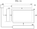
- FIG. 1A is a view schematically showing a stereoscopic display device according to an embodiment of the present disclosure.
- FIG. 1B is a view showing a relative position of a display panel and a light control panel of the stereoscopic display device according to the embodiment of the present disclosure, and a moving path of light passing through the light control panel.
- FIG. 2A is an enlarged view of P region in FIG. 1B .
- FIG. 2B is an enlarged view of R region in FIG. 1B .
- the stereoscopic display device may include a display panel 100.
- the display panel 100 may realize a specific image.
- the display panel 100 realizing a specific image may be referred to as the display panel displaying a specific image.
- 'to realize' may mean 'to display'.
- An image may be displayed to a user on a display device.
- the image may comprise comprises a plurality of frames.
- the display panel 100 may be an OLED panel in which a light-emitting element 140 is disposed between a first display substrate 110 and a second display substrate 180.
- the first display substrate 110 may support the light-emitting element 140.
- the first display substrate 110 may include an insulating material.
- the first display substrate 110 may include glass or plastic.
- the light-emitting element 140 may emit light displaying a specific color.
- the light-emitting element 140 may include a first display electrode 141, a light-emitting layer 142 and a second display electrode 143, which are sequentially stacked on the first display substrate 110.
- the first display electrode 141 may include a conductive material.
- the first display electrode 141 may include a material having high reflectance.
- the first display electrode 141 may include a metal, such as aluminum (Al) and/or silver (Ag).
- the first display electrode 141 may have a multi-layer structure.
- the first display electrode 141 may have a structure in which a reflective electrode formed of a material having high reflectance is disposed between transparent electrodes formed of transparent conductive material, such as ITO and IZO.
- the light-emitting layer 142 may generate light having luminance corresponding to a voltage difference between the first display electrode 141 and the second display electrode 143.
- the light-emitting layer 142 may include an emission material layer (EML) including an emission material.
- the emission material may include an inorganic material, an organic material or a hybrid material.
- the light-emitting layer 142 may have a multi-layer structure.
- the light-emitting layer 142 may further include at least one of a hole injection layer (HIL), a hole transport layer (HTL), an electron transport layer (ETL), and an electron injection layer (EIL).
- HIL hole injection layer
- HTL hole transport layer
- ETL electron transport layer
- EIL electron injection layer
- the second display electrode 143 may include a conductive material.
- the second display electrode 143 may include a material different from the first display electrode 141.
- the second display electrode 143 may be a transparent electrode formed of a transparent conductive material, such as ITO and IZO.
- ITO and IZO transparent conductive material
- a thin film transistor 120 may be disposed between the first display substrate 110 and the light-emitting element 140.
- the thin film transistor 120 may be turned on/off according to a gate signal supplied through a gate line.
- the light-emitting element 140 may be controlled by the thin film transistor 120.
- the thin film transistor 120 may apply a driving current corresponding to a data signal supplied through a data line to the first display electrode 141 of the light-emitting element 140.
- the thin film transistor 120 may include a semiconductor pattern, a gate insulating layer, a gate electrode, an interlayer insulating layer, a source electrode and a drain electrode.
- An over-coat layer 130 may be disposed between the thin film transistor 120 and the light-emitting element 140.
- the over-coat layer 130 may remove a thickness difference due to the thin film transistor 120.
- an upper surface of the over-coat layer 130 opposite to the first display substrate 110 may be a flat surface.
- the first display electrode 141 of the light-emitting element 140 may be electrically coupled to the drain electrode of the thin film transistor 120.
- the over-coat layer 130 may include an electrode contact hole partially exposing the drain electrode of the thin film transistor 120.
- the over-coat layer 130 may include an insulating material.
- the over-coat layer 130 may include an organic insulating material.
- a bank insulating layer 150 may be disposed on the over-coat layer 130.
- the light-emitting element 140 may be independently driven by the bank insulating layer 150.
- the bank insulating layer 150 may cover an edge of the first display electrode 141.
- the light-emitting layer 142 and the second display electrode 143 may be stacked on a portion of the first display electrode 141 which is not covered by the bank insulating layer 150.
- the light-emitting layer 142 and/or the second display electrode 143 may be extended onto the bank insulating layer 150.
- the bank insulating layer 150 may include an insulating material.
- the bank insulating layer 150 may include an organic insulating material.
- the bank insulating layer 150 may include a material different from the over-coat layer 130.
- An upper passivation layer 160 may be disposed on the light-emitting element 140.
- the upper passivation layer 160 may prevent damage to the light-emitting element 140 due to external impact and moisture.
- the upper passivation layer 160 may entirely cover a surface of the second display electrode 143 facing the second display substrate 180.
- the upper passivation layer 160 may include an insulating material.
- the upper passivation layer 160 may have a multi-layer structure.
- the upper passivation layer 160 may have a structure in which an organic layer formed of an organic material is disposed between inorganic layers formed of an inorganic material.
- the second display substrate 180 may be disposed on the upper passivation layer 160.
- the second display substrate 180 may include an insulating material.
- the second display substrate 180 may include a transparent material.
- the second display substrate 180 may include glass or plastic.
- the light emitted from the light-emitting element 140 may be emitted to the outside through the second display substrate 180.
- An adhesive layer 170 may be disposed between the upper passivation layer 160 and the second display substrate 180.
- the second display substrate 180 may be coupled to the first display substrate 110 in which the light-emitting element 140 is formed, by the adhesive layer 170.
- the adhesive layer 170 may have a multi-layer structure.
- the adhesive layer 170 may include a lower adhesive layer 171 and an upper adhesive layer 172 which are sequentially stacked.
- the upper adhesive layer 172 may include a moisture-absorbing material 170p.
- the lower adhesive layer 171 may relieve the stress applied to the light-emitting element 140 due to the expansion of the moisture-absorbing material 170p.
- a light control panel 200 may be disposed on the display panel 100.
- the moving direction of light passing through the light control panel 200 may be changed by the state of the light control panel 200.
- the light control panel 200 may include a water layer 260 and an oil layer 270 which are stacked between a first control substrate 210 and a second control substrate 220.
- the moving direction of the light passing through the light control panel 200 may be affected by an interface 200S between the water layer 260 and the oil layer 270.
- a 'moving direction' of light may be referred to as a 'direction' of light or a 'propagation direction' of light.
- the moving direction may not be changed for each frame, but may only be changed for specified frames.
- FIGS. 3A to 3C are views showing the emitting direction of light according to the state of the light control panel of the stereoscopic display device according to the embodiment of the present disclosure.
- the interface 200S between the water layer 260 and the oil layer 270 when the interface 200S between the water layer 260 and the oil layer 270 is inclined in a direction, light incident on the water layer 260 may be refracted.
- the interface 200S between the water layer 260 and the oil layer 270 when the interface 200S between the water layer 260 and the oil layer 270 is inclined in a rightward direction (the interface 200S is inclined at an angle ⁇ 1 with respect to a horizontal direction, as shown in FIG. 3B ), the moving direction of the light passing through the oil layer 270 may be inclined in the rightward direction with respect to the moving direction of the light incident on the water layer 260.
- the moving direction of the light may be inclined in the rightward direction, i.e. relative to a vertical direction, by the angle ⁇ 1 .
- the moving direction of the light passing through the oil layer 270 may be inclined in the left direction with respect to the moving direction of the light incident on the water layer 260.
- the moving direction of the light may be inclined in the leftward direction, i.e. relative to a vertical direction, by the angle ⁇ 2 .
- the inclination ⁇ 1 and ⁇ 2 of the light passing through the oil layer 270 may be the same as the inclination ⁇ 1 and ⁇ 2 of the interface 200S between the water layer 260 and the oil layer 270.
- the light control panel 200 may include control electrodes 230, 241 and 242 to control the interface 200S between the water layer 260 and the oil layer 270.
- the light control panel 200 may include lower control electrodes 230 which are disposed on the upper surface of the first control substrate 210, and a first upper control electrode 241 and a second upper control electrode 242 which are disposed on a lower surface of the second control substrate 220 facing the first control substrate 210.
- the second upper control electrode 242 may be spaced away from the first upper control electrode 241.
- An intermediate insulating layer 250 is disposed between the lower control electrodes 230 and the first upper control electrode 241, and between the lower control electrode 230 and the second upper control electrode 242.
- first upper control electrode 241 and the second upper control electrode 242 may be insulated from the lower control electrodes 230 by the intermediate insulating layer 250.
- the water layer 260 and the oil layer 270 may be disposed inside a space defined by the control electrodes 230, 241 and 242, and the intermediate insulating layer 250 (and optionally the first control substrate 210 and the second control substrate 220).
- the water layer 260 may be disposed between the lower control electrodes 230.
- the voltage applied to each of the lower control electrodes 230 may be the same.
- the oil layer 270 may be disposed between the first upper control electrode 241 and the second upper control electrode 242.
- a voltage applied to the second upper control electrode 242 may be different from a voltage applied to the first upper control electrode 241. For example, when the voltage applied to the first upper control electrode 241 is higher than the voltage applied to the second upper control electrode 242, the interface 200S between the water layer 260 and the oil layer 270 may be inclined in the rightward direction, as shown in FIG. 3B .
- the interface 200S between the water layer 260 and the oil layer 270 may be inclined in the leftward direction, as shown in FIG. 3C .
- the voltage applied to the first upper control electrode 241 and the voltage applied to the second upper control electrode 242 may be higher than the voltage applied to the lower control electrodes 230.
- the moving direction of the light passing through the light control panel 200 may be adjusted by the voltage applied to the control electrodes 230, 241 and 242 of the light control panel 200.
- the display panel 100 may be controlled by a display driver 300, as shown in FIGS. 1A and 1B .
- the display driver 300 may provide signals for realizing the image to the display panel 100.
- the display driver 300 may include a data driver 310 and a scan driver 320.
- the data driver 310 may provide the data signal to the display panel 100.
- the scan driver 320 may sequentially apply the scan signal to the display panel 100.
- the data signal applied by the data driver 310 may be synchronized with the scan signal applied by the scan driver 320.
- the display driver 300 may control the display panel 100 such that the specific image realized by the display panel 100 may be displayed in a time division manner. For example, the display driver 300 may divide each frame into a plurality of sub-frames, and may provide a signal for each sub-frame for realizing the specific image. The data driver 310 and the scan driver 320 may receive the signal from the display driver 300 for each sub-frame.
- the display driver 300 may receive a signal necessary for the operation from the timing controller 400.
- the timing controller 400 may provide digital video data and a source timing control signal to the data driver 310.
- the scan driver 320 may receive clock signals, reset clock signals and a start signal from the timing controller 400.
- the light control panel 200 may be controlled by a control panel driver 500.
- the control panel driver 500 may adjust the interface 200S between the water layer 260 and the oil layer 270 using the voltage applied to the control electrodes 230, 241 and 242 of the light control panel 200.
- the control panel driver 500 may be electrically connected to the timing controller 400.
- the stereoscopic display device may control the light control panel 200 in conjunction with the display panel 100.
- the control panel driver 500 may change the voltage applied to the first upper control electrode 241 and the second upper control electrode 242 for each frame.
- the interface 200S between the water layer 260 and the oil layer 270 may be changed for each frame.
- the moving direction of the light passing through the light control panel 200 may be changed for each frame.
- the light emitted in the different direction(s) by the light control panel 200 may be overlapped at a specific location to generate a virtual image 'I'.
- the stereoscopic display device may realize the virtual image 'I' using light field technology by the display panel 100 and the light control panel 200. Therefore, in the stereoscopic display device according to the embodiment of the present disclosure, the visibility of the virtual image 'I' may be increased.
- a micro-lens array 600 may be disposed between the display panel 100 and the light control panel 200.
- the efficiency of the light emitted from the display panel 100 may be increased.
- a convex lens 700 may be disposed on the light control panel 200.
- a combiner 800 may be disposed on the convex lens 700.
- the combiner 800 may reflect light incident in the first direction, and may transmit light incident in the second direction.
- the combiner 800 may include a beam splitter.
- the virtual image 'I' realized by the display panel 100 and the light control panel 200 may be reflected toward the user by the combiner 800.
- the combiner 800 may provide the actual image to the user by transmitting the light.
- the virtual image 'I' generated by the display panel 100 and the light control panel 200 may be realized on the actual image.
- the stereoscopic display device may generate the stereoscopic image including the virtual image 'I' realized by the light control panel 200 using light field technology.
- the virtual image 'I' may have focus-convergence matching with the actual image. Therefore, in the stereoscopic display device according to the embodiment of the present disclosure, the visibility of the stereoscopic image including the virtual image 'I' realized on the actual image and the actual image may be increased.
- the stereoscopic display device is described such that the light control panel 200 is an electro-wetting device including the interface 200S between the water layer 260 and the oil layer 270.
- the stereoscopic display device may include various types of the light control panel 200.
- the light control panel 200 may include a liquid crystal layer 280 between the first control substrate 210 and the second control substrate 220, as shown in FIG. 4 . That is, in the stereoscopic display device according to another embodiment of the present disclosure, the light control panel 200 may be a liquid crystal panel.
- the light control panel 200 may include control electrodes 291 and 292, and insulating layers 293 and 294 to form an inclined virtual boundary in the liquid crystal layer 280.
- the liquid crystal layer 280 may be disposed between the control electrodes 291 and 292.
- Lower control electrodes 291 on a surface of the first control substrate 210 facing the second control substrate 220 may be separated from each other.
- Upper control electrodes 292 on a surface of the second control substrate 220 facing the first control substrate 210 may be in a plate shape.
- the inclined virtual boundary may be formed inside the liquid crystal layer 280 by adjusting the voltage applied to the lower control electrodes 291, as shown in FIGS. 5A and 5B . Therefore, in the stereoscopic display device according to another embodiment of the present disclosure, the degree of freedom for a forming process may be improved.
- the stereoscopic display device is described such that light beams of the light emitted from the display panel 100 are parallel with each other, and the moving direction of the light emitted from the display panel 100 is changed by the light control panel 200 for each frame, so that the specific image may be generated between the light control panel 200 and the combiner 800.
- the stereoscopic display device may generate the specific image between the display panel 100 and the light control panel 200.
- the moving direction of the light emitted from the display panel 100 may be changed in order to use light field technology, and light beams of the light passing through the light control panel 200 may be parallel with each other, so that the virtual image 'I' may be provided to the user, as shown FIG. 6 . That is, in the stereoscopic display device according to another embodiment of the present disclosure, the light emitted from the display panel 100 may be provided to the user by or after crossing between the display panel 100 and the light control panel 200. Thus, in the stereoscopic display device according to another embodiment of the present disclosure, a distance between the image realized by the display panel 100 and the combiner 800 may be increased.
- the display location of the virtual image 'I' recognized by (i.e. apparent to) the user may be the same as the focusing distance (i.e. the position of the focus) of the convex lens 700.
- the user may recognize that the virtual image 'I' is realized at a location which is spaced away from the user by a value of a sum of a distance between the image realized by the display panel 100 and the combiner 800 and a distance between the combiner 800 and the user. That is, the display distance of the virtual image 'I' provided to the user may be proportional to a distance between the image realized by the display panel 100 and the combiner 800, and a distance between the combiner 800 and the user. Thereby, in the stereoscopic display device according to the embodiment of the present disclosure, the variable range of the location of the virtual image 'I' recognized by the user may be increased.
- the stereoscopic display device may realize the stereoscopic image using light field technology by the light control panel.
- the stereoscopic display device may make the virtual image have focus-convergence matching with the actual image.
- the visibility of the stereoscopic image provided to the user may be increased.
Landscapes
- Physics & Mathematics (AREA)
- General Physics & Mathematics (AREA)
- Optics & Photonics (AREA)
- Nonlinear Science (AREA)
- Mathematical Physics (AREA)
- Crystallography & Structural Chemistry (AREA)
- Chemical & Material Sciences (AREA)
- Engineering & Computer Science (AREA)
- Multimedia (AREA)
- Signal Processing (AREA)
- Geometry (AREA)
- Testing, Inspecting, Measuring Of Stereoscopic Televisions And Televisions (AREA)
- Electroluminescent Light Sources (AREA)
Abstract
Description
- This application claims the priority benefit of Korean Patent Application No.
10-2017-0184365, filed on December 29, 2017 - The present disclosure relates to a stereoscopic display device realizing a stereoscopic image using light field technology.
- Generally, a display device includes a display panel which realizes an image. For example, the display device may include a liquid crystal panel having a liquid crystal, and/or an OLED panel having an organic light-emitting element.
- The display device may provide a stereoscopic image to a user. The stereoscopic image may be realized by a binocular disparity technology in which the display panel provides different images to the left eye and the right eye of the user. The stereoscopic image may include a virtual image realized on an actual image. However, in the stereoscopic display device using the binocular disparity technology, the virtual image realized by the display panel may have focus-convergence mismatching with the actual image. Thus, in the stereoscopic display device, the visibility of the stereoscopic image may be decreased.
- Accordingly, the present disclosure is directed to a stereoscopic display device that substantially obviates one or more problems due to limitations and disadvantages of the related art.
- An object of the present disclosure is to provide a stereoscopic display device capable of increasing the visibility of the stereoscopic image.
- Another object of the present disclosure is to provide a stereoscopic display device in which a virtual image realized on an actual image may have focus-convergence matching with the actual image.
- Additional advantages, objects, and features of the disclosure will be set forth in part in the description which follows and in part will become apparent to those having ordinary skill in the art upon examination of the following or may be learned from practice of the disclosure. The objectives and other advantages of the disclosure may be realized and attained by the structure particularly pointed out in the written description and claims hereof as well as the appended drawings.
- To achieve these objects and other advantages and in accordance with the purpose of the disclosure, as embodied and broadly described herein, there is provided a stereoscopic display device including a display panel. The display panel is driven by a display driver. A light control panel is disposed on the display panel. The light control panel is controlled by a control panel driver. The moving direction of light passing through the light control panel is changed by the control panel driver for each frame.
- The display panel may display a specific image in a time-division by the display driver.
- The light control panel may include a water layer and an oil layer which are stacked between a first control substrate and a second control substrate.
- An interface between the water layer and the oil layer may be changed for each frame.
- The light control panel may further include a first control electrode and a second control electrode which are disposed on the second control substrate. The second control electrode may be spaced away from the first control electrode. The oil layer may be disposed between the first control electrode and the second control electrode. The voltage difference between the first control electrode and the second control electrode may be changed by the control panel driver for each frame.
- The display panel may include a light-emitting element between a first display substrate and a second display substrate.
- A micro-lens array may be disposed between the display panel and the light control panel.
- A convex lens may be disposed on the light control panel. A combiner may be disposed on the convex lens.
- The accompanying drawings, which are included to provide a further understanding of the disclosure and are incorporated in and constitute a part of this application, illustrate embodiment(s) of the disclosure and together with the description serve to explain the principle of the disclosure. In the drawings:
-
FIG. 1A is a view schematically showing a stereoscopic display device according to an embodiment of the present disclosure; -
FIG. 1B is a view showing a relative position of a display panel and a light control panel of the stereoscopic display device according to the embodiment of the present disclosure, and a moving path of light passing through the light control panel; -
FIG. 2A is an enlarged view of P region inFIG. 1B ; -
FIG. 2B is an enlarged view of R region inFIG. 1B ; -
FIGS. 3A to 3C are views showing the emitting direction of light according to the state of the light control panel of the stereoscopic display device according to the embodiment of the present disclosure; -
FIGS. 4 ,5A and 5B are views showing the light control panel of the stereoscopic display device according to another embodiment of the present disclosure, and the emitting direction of light; and -
FIG. 6 is a view showing a relative position of the display panel and the light control panel of the stereoscopic display device according to further another embodiment of the present disclosure, and a moving path of light passing through the light control panel. - Hereinafter, details related to the above objects, technical configurations, and operational effects of the embodiments of the present disclosure will be clearly understood by the following detailed description with reference to the drawings, which illustrate some embodiments of the present disclosure. Here, the embodiments of the present disclosure are provided in order to allow the technical features of the present disclosure to be satisfactorily transferred to those skilled in the art, and thus the present disclosure may be embodied in other forms and is not limited to the embodiments described below.
- In addition, the same or extremely similar elements may be designated by the same reference numerals throughout the specification, and in the drawings, the lengths and thickness of layers and regions may be exaggerated for convenience. It will be understood that, when a first element is referred to as being "on" a second element, although the first element may be disposed on the second element so as to come into contact with the second element, a third element may be interposed between the first element and the second element.
- Here, terms such as, for example, "first" and "second" may be used to distinguish any one element with another element. However, the first element and the second element may be arbitrarily named according to the convenience of those skilled in the art without departing the technical sprit of the present disclosure.
- The terms used in the specification of the present disclosure are merely used in order to describe particular embodiments, and are not intended to limit the scope of the present disclosure. For example, an element described in the singular form is intended to include a plurality of elements unless the context clearly indicates otherwise. In addition, in the specification of the present disclosure, it will be further understood that the terms "comprises" and "includes" specify the presence of stated features, integers, steps, operations, elements, components, and/or combinations thereof, but do not preclude the presence or addition of one or more other features, integers, steps, operations, elements, components, and/or combinations.
- Unless otherwise defined, all terms (including technical and scientific terms) used herein have the same meaning as that commonly understood by one of ordinary skill in the art to which example embodiments belong. It will be further understood that terms, such as those defined in commonly used dictionaries, should be interpreted as having a meaning that is consistent with their meaning in the context of the relevant art and should not be interpreted in an idealized or overly formal sense unless expressly so defined herein.
-
FIG. 1A is a view schematically showing a stereoscopic display device according to an embodiment of the present disclosure.FIG. 1B is a view showing a relative position of a display panel and a light control panel of the stereoscopic display device according to the embodiment of the present disclosure, and a moving path of light passing through the light control panel.FIG. 2A is an enlarged view of P region inFIG. 1B .FIG. 2B is an enlarged view of R region inFIG. 1B . - Referring to
FIGS. 1A ,1B ,2A and 2B , the stereoscopic display device according to the embodiment of the present disclosure may include adisplay panel 100. Thedisplay panel 100 may realize a specific image. As used herein, thedisplay panel 100 realizing a specific image may be referred to as the display panel displaying a specific image. In other words, as used herein, 'to realize' may mean 'to display'. An image may be displayed to a user on a display device. The image may comprise comprises a plurality of frames. For example, thedisplay panel 100 may be an OLED panel in which a light-emittingelement 140 is disposed between afirst display substrate 110 and asecond display substrate 180. - The
first display substrate 110 may support the light-emittingelement 140. Thefirst display substrate 110 may include an insulating material. For example, thefirst display substrate 110 may include glass or plastic. - The light-emitting
element 140 may emit light displaying a specific color. For example, the light-emittingelement 140 may include afirst display electrode 141, a light-emittinglayer 142 and asecond display electrode 143, which are sequentially stacked on thefirst display substrate 110. - The
first display electrode 141 may include a conductive material. Thefirst display electrode 141 may include a material having high reflectance. For example, thefirst display electrode 141 may include a metal, such as aluminum (Al) and/or silver (Ag). Thefirst display electrode 141 may have a multi-layer structure. For example, thefirst display electrode 141 may have a structure in which a reflective electrode formed of a material having high reflectance is disposed between transparent electrodes formed of transparent conductive material, such as ITO and IZO. - The light-emitting
layer 142 may generate light having luminance corresponding to a voltage difference between thefirst display electrode 141 and thesecond display electrode 143. For example, the light-emittinglayer 142 may include an emission material layer (EML) including an emission material. The emission material may include an inorganic material, an organic material or a hybrid material. The light-emittinglayer 142 may have a multi-layer structure. For example, the light-emittinglayer 142 may further include at least one of a hole injection layer (HIL), a hole transport layer (HTL), an electron transport layer (ETL), and an electron injection layer (EIL). - The
second display electrode 143 may include a conductive material. Thesecond display electrode 143 may include a material different from thefirst display electrode 141. For example, thesecond display electrode 143 may be a transparent electrode formed of a transparent conductive material, such as ITO and IZO. Thus, in the light-emittingelement 140 of the stereoscopic display device according to the embodiment of the present disclosure, the light generated by the light-emittinglayer 142 may be emitted through thesecond display electrode 143. - A
thin film transistor 120 may be disposed between thefirst display substrate 110 and the light-emittingelement 140. Thethin film transistor 120 may be turned on/off according to a gate signal supplied through a gate line. The light-emittingelement 140 may be controlled by thethin film transistor 120. For example, thethin film transistor 120 may apply a driving current corresponding to a data signal supplied through a data line to thefirst display electrode 141 of the light-emittingelement 140. Thethin film transistor 120 may include a semiconductor pattern, a gate insulating layer, a gate electrode, an interlayer insulating layer, a source electrode and a drain electrode. - An
over-coat layer 130 may be disposed between thethin film transistor 120 and the light-emittingelement 140. Theover-coat layer 130 may remove a thickness difference due to thethin film transistor 120. For example, an upper surface of theover-coat layer 130 opposite to thefirst display substrate 110 may be a flat surface. Thefirst display electrode 141 of the light-emittingelement 140 may be electrically coupled to the drain electrode of thethin film transistor 120. For example, theover-coat layer 130 may include an electrode contact hole partially exposing the drain electrode of thethin film transistor 120. Theover-coat layer 130 may include an insulating material. For example, theover-coat layer 130 may include an organic insulating material. - A
bank insulating layer 150 may be disposed on theover-coat layer 130. The light-emittingelement 140 may be independently driven by thebank insulating layer 150. For example, thebank insulating layer 150 may cover an edge of thefirst display electrode 141. The light-emittinglayer 142 and thesecond display electrode 143 may be stacked on a portion of thefirst display electrode 141 which is not covered by thebank insulating layer 150. The light-emittinglayer 142 and/or thesecond display electrode 143 may be extended onto thebank insulating layer 150. Thebank insulating layer 150 may include an insulating material. For example, thebank insulating layer 150 may include an organic insulating material. Thebank insulating layer 150 may include a material different from theover-coat layer 130. - An
upper passivation layer 160 may be disposed on the light-emittingelement 140. Theupper passivation layer 160 may prevent damage to the light-emittingelement 140 due to external impact and moisture. For example, theupper passivation layer 160 may entirely cover a surface of thesecond display electrode 143 facing thesecond display substrate 180. Theupper passivation layer 160 may include an insulating material. Theupper passivation layer 160 may have a multi-layer structure. For example, theupper passivation layer 160 may have a structure in which an organic layer formed of an organic material is disposed between inorganic layers formed of an inorganic material. - The
second display substrate 180 may be disposed on theupper passivation layer 160. Thesecond display substrate 180 may include an insulating material. Thesecond display substrate 180 may include a transparent material. For example, thesecond display substrate 180 may include glass or plastic. Thus, the light emitted from the light-emittingelement 140 may be emitted to the outside through thesecond display substrate 180. - An
adhesive layer 170 may be disposed between theupper passivation layer 160 and thesecond display substrate 180. For example, thesecond display substrate 180 may be coupled to thefirst display substrate 110 in which the light-emittingelement 140 is formed, by theadhesive layer 170. Theadhesive layer 170 may have a multi-layer structure. For example, theadhesive layer 170 may include a loweradhesive layer 171 and an upperadhesive layer 172 which are sequentially stacked. The upperadhesive layer 172 may include a moisture-absorbingmaterial 170p. The loweradhesive layer 171 may relieve the stress applied to the light-emittingelement 140 due to the expansion of the moisture-absorbingmaterial 170p. - A
light control panel 200 may be disposed on thedisplay panel 100. The moving direction of light passing through thelight control panel 200 may be changed by the state of thelight control panel 200. For example, thelight control panel 200 may include awater layer 260 and anoil layer 270 which are stacked between afirst control substrate 210 and asecond control substrate 220. The moving direction of the light passing through thelight control panel 200 may be affected by aninterface 200S between thewater layer 260 and theoil layer 270. As used herein, a 'moving direction' of light may be referred to as a 'direction' of light or a 'propagation direction' of light. In some examples, the moving direction may not be changed for each frame, but may only be changed for specified frames. -
FIGS. 3A to 3C are views showing the emitting direction of light according to the state of the light control panel of the stereoscopic display device according to the embodiment of the present disclosure. - As shown in
FIG. 3A , when theinterface 200S between thewater layer 260 and theoil layer 270 is parallel with an upper surface of thefirst control substrate 210 facing thesecond control substrate 220, light passing through thewater layer 260 may transmit through theoil layer 270 without the change of the moving direction. - As shown in
FIGS. 3B and3C , when theinterface 200S between thewater layer 260 and theoil layer 270 is inclined in a direction, light incident on thewater layer 260 may be refracted. For example, as shown inFIG. 3B , when theinterface 200S between thewater layer 260 and theoil layer 270 is inclined in a rightward direction (theinterface 200S is inclined at an angle Θ1 with respect to a horizontal direction, as shown inFIG. 3B ), the moving direction of the light passing through theoil layer 270 may be inclined in the rightward direction with respect to the moving direction of the light incident on thewater layer 260. The moving direction of the light may be inclined in the rightward direction, i.e. relative to a vertical direction, by the angle Θ1. For example, as shown inFIG. 3C , when theinterface 200S between thewater layer 260 and theoil layer 270 is inclined in a leftward direction (theinterface 200S is inclined at an angle Θ2 with respect to a horizontal direction, as shown inFIG. 3C ), the moving direction of the light passing through theoil layer 270 may be inclined in the left direction with respect to the moving direction of the light incident on thewater layer 260. The moving direction of the light may be inclined in the leftward direction, i.e. relative to a vertical direction, by the angle θ2. In other words, the inclination θ1 and θ2 of the light passing through theoil layer 270 may be the same as the inclination θ1 and θ2 of theinterface 200S between thewater layer 260 and theoil layer 270. - The
light control panel 200 may includecontrol electrodes interface 200S between thewater layer 260 and theoil layer 270. For example, thelight control panel 200 may includelower control electrodes 230 which are disposed on the upper surface of thefirst control substrate 210, and a firstupper control electrode 241 and a secondupper control electrode 242 which are disposed on a lower surface of thesecond control substrate 220 facing thefirst control substrate 210. The secondupper control electrode 242 may be spaced away from the firstupper control electrode 241. An intermediate insulatinglayer 250 is disposed between thelower control electrodes 230 and the firstupper control electrode 241, and between thelower control electrode 230 and the secondupper control electrode 242. For example, the firstupper control electrode 241 and the secondupper control electrode 242 may be insulated from thelower control electrodes 230 by the intermediate insulatinglayer 250. Thewater layer 260 and theoil layer 270 may be disposed inside a space defined by thecontrol electrodes first control substrate 210 and the second control substrate 220). - The
water layer 260 may be disposed between thelower control electrodes 230. The voltage applied to each of thelower control electrodes 230 may be the same. Theoil layer 270 may be disposed between the firstupper control electrode 241 and the secondupper control electrode 242. A voltage applied to the secondupper control electrode 242 may be different from a voltage applied to the firstupper control electrode 241. For example, when the voltage applied to the firstupper control electrode 241 is higher than the voltage applied to the secondupper control electrode 242, theinterface 200S between thewater layer 260 and theoil layer 270 may be inclined in the rightward direction, as shown inFIG. 3B . When the voltage applied to the firstupper control electrode 241 is lower than the voltage applied to the secondupper control electrode 242, theinterface 200S between thewater layer 260 and theoil layer 270 may be inclined in the leftward direction, as shown inFIG. 3C . The voltage applied to the firstupper control electrode 241 and the voltage applied to the secondupper control electrode 242 may be higher than the voltage applied to thelower control electrodes 230. Thus, in the stereoscopic display device according to the embodiment of the present invention, the moving direction of the light passing through thelight control panel 200 may be adjusted by the voltage applied to thecontrol electrodes light control panel 200. - The
display panel 100 may be controlled by adisplay driver 300, as shown inFIGS. 1A and1B . Thedisplay driver 300 may provide signals for realizing the image to thedisplay panel 100. For example, thedisplay driver 300 may include adata driver 310 and ascan driver 320. Thedata driver 310 may provide the data signal to thedisplay panel 100. Thescan driver 320 may sequentially apply the scan signal to thedisplay panel 100. The data signal applied by thedata driver 310 may be synchronized with the scan signal applied by thescan driver 320. - The
display driver 300 may control thedisplay panel 100 such that the specific image realized by thedisplay panel 100 may be displayed in a time division manner. For example, thedisplay driver 300 may divide each frame into a plurality of sub-frames, and may provide a signal for each sub-frame for realizing the specific image. Thedata driver 310 and thescan driver 320 may receive the signal from thedisplay driver 300 for each sub-frame. - The
display driver 300 may receive a signal necessary for the operation from thetiming controller 400. For example, thetiming controller 400 may provide digital video data and a source timing control signal to thedata driver 310. Thescan driver 320 may receive clock signals, reset clock signals and a start signal from thetiming controller 400. - The
light control panel 200 may be controlled by acontrol panel driver 500. For example, thecontrol panel driver 500 may adjust theinterface 200S between thewater layer 260 and theoil layer 270 using the voltage applied to thecontrol electrodes light control panel 200. Thecontrol panel driver 500 may be electrically connected to thetiming controller 400. Thus, the stereoscopic display device according to the embodiment of the present disclosure may control thelight control panel 200 in conjunction with thedisplay panel 100. - The
control panel driver 500 may change the voltage applied to the firstupper control electrode 241 and the secondupper control electrode 242 for each frame. For example, theinterface 200S between thewater layer 260 and theoil layer 270 may be changed for each frame. Thus, in the stereoscopic display device according the embodiment of the present disclosure, the moving direction of the light passing through thelight control panel 200 may be changed for each frame. For example, in the stereoscopic display device according the embodiment of the present disclosure, the light emitted in the different direction(s) by thelight control panel 200 may be overlapped at a specific location to generate a virtual image 'I'. That is, the stereoscopic display device according the embodiment of the present disclosure may realize the virtual image 'I' using light field technology by thedisplay panel 100 and thelight control panel 200. Therefore, in the stereoscopic display device according to the embodiment of the present disclosure, the visibility of the virtual image 'I' may be increased. - A
micro-lens array 600 may be disposed between thedisplay panel 100 and thelight control panel 200. Thus, in the stereoscopic display device according to the embodiment of the present disclosure, the efficiency of the light emitted from thedisplay panel 100 may be increased. Aconvex lens 700 may be disposed on thelight control panel 200. Acombiner 800 may be disposed on theconvex lens 700. Thecombiner 800 may reflect light incident in the first direction, and may transmit light incident in the second direction. For example, thecombiner 800 may include a beam splitter. The virtual image 'I' realized by thedisplay panel 100 and thelight control panel 200 may be reflected toward the user by thecombiner 800. Thecombiner 800 may provide the actual image to the user by transmitting the light. Thus, in the stereoscopic display device according to the embodiment of the present disclosure, the virtual image 'I' generated by thedisplay panel 100 and thelight control panel 200 may be realized on the actual image. - Accordingly, the stereoscopic display device according to the embodiment of the present disclosure may generate the stereoscopic image including the virtual image 'I' realized by the
light control panel 200 using light field technology. Thus, in the stereoscopic display device according to the embodiment of the present disclosure, the virtual image 'I' may have focus-convergence matching with the actual image. Therefore, in the stereoscopic display device according to the embodiment of the present disclosure, the visibility of the stereoscopic image including the virtual image 'I' realized on the actual image and the actual image may be increased. - The stereoscopic display device according to the embodiment of the present disclosure is described such that the
light control panel 200 is an electro-wetting device including theinterface 200S between thewater layer 260 and theoil layer 270. However, the stereoscopic display device according to another embodiment of the present disclosure may include various types of thelight control panel 200. For example, in the stereoscopic display device according to another embodiment of the present disclosure, thelight control panel 200 may include aliquid crystal layer 280 between thefirst control substrate 210 and thesecond control substrate 220, as shown inFIG. 4 . That is, in the stereoscopic display device according to another embodiment of the present disclosure, thelight control panel 200 may be a liquid crystal panel. Thelight control panel 200 may includecontrol electrodes layers liquid crystal layer 280. For example, theliquid crystal layer 280 may be disposed between thecontrol electrodes Lower control electrodes 291 on a surface of thefirst control substrate 210 facing thesecond control substrate 220 may be separated from each other.Upper control electrodes 292 on a surface of thesecond control substrate 220 facing thefirst control substrate 210 may be in a plate shape. Thus, in the stereoscopic display device according to another embodiment of the present disclosure, the inclined virtual boundary may be formed inside theliquid crystal layer 280 by adjusting the voltage applied to thelower control electrodes 291, as shown inFIGS. 5A and 5B . Therefore, in the stereoscopic display device according to another embodiment of the present disclosure, the degree of freedom for a forming process may be improved. - The stereoscopic display device according to the embodiment of the present disclosure is described such that light beams of the light emitted from the
display panel 100 are parallel with each other, and the moving direction of the light emitted from thedisplay panel 100 is changed by thelight control panel 200 for each frame, so that the specific image may be generated between thelight control panel 200 and thecombiner 800. However, the stereoscopic display device according to another embodiment of the present disclosure may generate the specific image between thedisplay panel 100 and thelight control panel 200. For example, in the stereoscopic display device according to another embodiment of the present disclosure, the moving direction of the light emitted from thedisplay panel 100 may be changed in order to use light field technology, and light beams of the light passing through thelight control panel 200 may be parallel with each other, so that the virtual image 'I' may be provided to the user, as shownFIG. 6 . That is, in the stereoscopic display device according to another embodiment of the present disclosure, the light emitted from thedisplay panel 100 may be provided to the user by or after crossing between thedisplay panel 100 and thelight control panel 200. Thus, in the stereoscopic display device according to another embodiment of the present disclosure, a distance between the image realized by thedisplay panel 100 and thecombiner 800 may be increased. The display location of the virtual image 'I' recognized by (i.e. apparent to) the user may be the same as the focusing distance (i.e. the position of the focus) of theconvex lens 700. For example, the user may recognize that the virtual image 'I' is realized at a location which is spaced away from the user by a value of a sum of a distance between the image realized by thedisplay panel 100 and thecombiner 800 and a distance between thecombiner 800 and the user. That is, the display distance of the virtual image 'I' provided to the user may be proportional to a distance between the image realized by thedisplay panel 100 and thecombiner 800, and a distance between thecombiner 800 and the user. Thereby, in the stereoscopic display device according to the embodiment of the present disclosure, the variable range of the location of the virtual image 'I' recognized by the user may be increased. - In the result, the stereoscopic display device according to the embodiments of the present disclosure may realize the stereoscopic image using light field technology by the light control panel. Thus, the stereoscopic display device according to the embodiments of the present disclosure may make the virtual image have focus-convergence matching with the actual image. Thereby, in the stereoscopic display device according to the embodiments of the present disclosure, the visibility of the stereoscopic image provided to the user may be increased.
- The following clauses are also disclosed:
- 1. A stereoscopic display device comprising:
- a display driver driving a display panel;
- a light control panel on the display panel; and
- a control panel driver controlling the light control panel,
- wherein the control panel driver changes a moving direction of light passing through the light control panel for each frame.
- 2. The stereoscopic display device according to
clause 1, wherein the display driver displays a specific image in a time-division by the display panel. - 3. The stereoscopic display device according to any preceding clause, wherein the light control panel includes a water layer and an oil layer which are stacked between a first control substrate and a second control substrate.
- 4. The stereoscopic display device according to clause 3, wherein an interface between the water layer and the oil layer is changed for each frame.
- 5. The stereoscopic display device according to clause 3 or clause 4, wherein the light control panel further includes a first control electrode and a second control electrode which are disposed on the second control substrate,
wherein the second control electrode is spaced away from the first control electrode,
wherein the oil layer is disposed between the first control electrode and the second control electrode, and
wherein the voltage difference between the first control electrode and the second control electrode is changed by the control panel driver for each frame. - 6. The stereoscopic display device according to any preceding clause, wherein the display panel includes a light-emitting element between a first display substrate and a second display substrate.
- 7. The stereoscopic display device according to any preceding clause, further comprising a micro-lens array between the display panel and the light control panel.
- 8. The stereoscopic display device according to any preceding clause, further comprising a convex lens on the light control panel, and a combiner on the convex lens.
Claims (12)
- A stereoscopic display device comprising:a display panel;a display driver configured to drive the display panel;a light control panel on the display panel; anda control panel driver configured to control the light control panel,wherein, for each frame of a plurality of frames for display by the display panel, the control panel driver is configured to change a direction of light passing through the light control panel.
- The stereoscopic display device according to claim 1, wherein the display driver is configured to drive the display panel in a time-division manner.
- The stereoscopic display device according to any preceding claim, wherein the light control panel includes a water layer and an oil layer which are stacked between a first control substrate and a second control substrate.
- The stereoscopic display device according to claim 3, wherein, for each frame of the plurality of frames, an interface between the water layer and the oil layer is configured to be changed.
- The stereoscopic display device according to claim 3 or claim 4, wherein the light control panel further includes a first control electrode and a second control electrode which are disposed on the second control substrate,
wherein the second control electrode is spaced away from the first control electrode,
wherein the oil layer is disposed between the first control electrode and the second control electrode, and
wherein, for each frame of the plurality of frames, the voltage difference between the first control electrode and the second control electrode is configured to be changed by the control panel driver. - The stereoscopic display device according to any preceding claim, wherein the display panel includes a light-emitting element between a first display substrate and a second display substrate.
- The stereoscopic display device according to any preceding claim, further comprising a micro-lens array between the display panel and the light control panel.
- The stereoscopic display device according to any preceding claim, further comprising a convex lens on the light control panel, and a combiner on the convex lens.
- The stereoscopic display device according to claim 1, wherein the light control panel includes a liquid crystal layer between a first control substrate and a second control substrate.
- The stereoscopic display device according to claim 9, wherein, for each frame of the plurality of frames, a virtual boundary formed inside the liquid crystal layer is configured to be changed.
- The stereoscopic display device according to claim 9 or claim 10, wherein the light control panel further includes a first control electrode which is disposed on the second control substrate,
wherein, for each frame of the plurality of frames, the voltage applied to the first control electrode is configured to be changed by the control panel driver. - The stereoscopic display device according to claim 5, comprising a plurality of first control electrodes and a plurality of second control electrodes.
Applications Claiming Priority (1)
| Application Number | Priority Date | Filing Date | Title |
|---|---|---|---|
| KR1020170184365A KR102455583B1 (en) | 2017-12-29 | 2017-12-29 | Stereoscopic Display apparatus |
Publications (2)
| Publication Number | Publication Date |
|---|---|
| EP3505993A1 true EP3505993A1 (en) | 2019-07-03 |
| EP3505993B1 EP3505993B1 (en) | 2025-10-15 |
Family
ID=64744438
Family Applications (1)
| Application Number | Title | Priority Date | Filing Date |
|---|---|---|---|
| EP18213057.5A Active EP3505993B1 (en) | 2017-12-29 | 2018-12-17 | Stereoscopic display device |
Country Status (4)
| Country | Link |
|---|---|
| US (1) | US10871683B2 (en) |
| EP (1) | EP3505993B1 (en) |
| KR (1) | KR102455583B1 (en) |
| CN (1) | CN110012282B (en) |
Families Citing this family (1)
| Publication number | Priority date | Publication date | Assignee | Title |
|---|---|---|---|---|
| KR102790277B1 (en) * | 2020-11-18 | 2025-04-03 | 삼성전자주식회사 | Display apparatus and controlling method thereof |
Citations (3)
| Publication number | Priority date | Publication date | Assignee | Title |
|---|---|---|---|---|
| TW201118420A (en) * | 2009-11-24 | 2011-06-01 | Seereal Technologies Sa | Three-dimensional image display device |
| US20130208196A1 (en) * | 2012-02-09 | 2013-08-15 | Samsung Display Co., Ltd. | Liquid crystal lens panel and display apparatus having the same |
| US20140126038A1 (en) * | 2012-11-06 | 2014-05-08 | Samsung Electronics Co., Ltd. | Electrowetting prism device and multi-view 3d image display apparatus including the same |
Family Cites Families (7)
| Publication number | Priority date | Publication date | Assignee | Title |
|---|---|---|---|---|
| GB201011829D0 (en) * | 2010-07-14 | 2010-09-01 | Two Trees Photonics Ltd | Display system |
| US8848040B2 (en) * | 2010-10-08 | 2014-09-30 | 3Dv Co., Ltd. | 3D display system with active shutter plate |
| KR101957837B1 (en) * | 2012-11-26 | 2019-03-13 | 엘지디스플레이 주식회사 | Display Device Including Line Light Source And Method Of Driving The Same |
| WO2015065345A1 (en) * | 2013-10-30 | 2015-05-07 | Empire Technology Development Llc | Holographic image generation and reconstruction |
| US10203499B2 (en) * | 2015-08-24 | 2019-02-12 | Finisar Corporation | Image projection system |
| US10375379B2 (en) * | 2015-09-17 | 2019-08-06 | Innolux Corporation | 3D display device |
| CN105611279B (en) * | 2015-12-23 | 2017-12-15 | 四川大学 | The removing method of augmented reality integration imaging 3D display pattern distortion |
-
2017
- 2017-12-29 KR KR1020170184365A patent/KR102455583B1/en active Active
-
2018
- 2018-11-30 CN CN201811452830.2A patent/CN110012282B/en active Active
- 2018-12-03 US US16/208,359 patent/US10871683B2/en active Active
- 2018-12-17 EP EP18213057.5A patent/EP3505993B1/en active Active
Patent Citations (3)
| Publication number | Priority date | Publication date | Assignee | Title |
|---|---|---|---|---|
| TW201118420A (en) * | 2009-11-24 | 2011-06-01 | Seereal Technologies Sa | Three-dimensional image display device |
| US20130208196A1 (en) * | 2012-02-09 | 2013-08-15 | Samsung Display Co., Ltd. | Liquid crystal lens panel and display apparatus having the same |
| US20140126038A1 (en) * | 2012-11-06 | 2014-05-08 | Samsung Electronics Co., Ltd. | Electrowetting prism device and multi-view 3d image display apparatus including the same |
Also Published As
| Publication number | Publication date |
|---|---|
| KR102455583B1 (en) | 2022-10-17 |
| CN110012282B (en) | 2022-04-12 |
| EP3505993B1 (en) | 2025-10-15 |
| CN110012282A (en) | 2019-07-12 |
| US20190204692A1 (en) | 2019-07-04 |
| KR20190081661A (en) | 2019-07-09 |
| US10871683B2 (en) | 2020-12-22 |
Similar Documents
| Publication | Publication Date | Title |
|---|---|---|
| US12262584B2 (en) | Light-emitting device and electronic apparatus | |
| US11002984B2 (en) | Stereoscopic display apparatus | |
| US10877310B2 (en) | Transparent display apparatus | |
| US10871683B2 (en) | Stereoscopic display device | |
| US10816819B1 (en) | Stereoscopic display device having a barrier panel | |
| JP2015169937A (en) | Electro-optical device, method of manufacturing electro-optical device, and electronic apparatus | |
| CN109709678B (en) | Display device and method for manufacturing the same | |
| CN113132713A (en) | 3D display device with lenticular lens | |
| KR102883431B1 (en) | Stereoscopic display apparatus having a display panel and lenticular lenses | |
| US20190079307A1 (en) | Stereoscopic display device having a barrier panel | |
| KR20150061967A (en) | Display device | |
| KR102649828B1 (en) | Stereoscopic Display apparatus and Method for driving the same | |
| US10855975B2 (en) | Stereoscopic display device having a barrier panel | |
| US20250204190A1 (en) | Display device | |
| KR102883430B1 (en) | 3D display apparatus having lenticular lens | |
| CN119947458A (en) | Display device | |
| KR20110128020A (en) | Stereoscopic image display device and drving method thereof |
Legal Events
| Date | Code | Title | Description |
|---|---|---|---|
| PUAI | Public reference made under article 153(3) epc to a published international application that has entered the european phase |
Free format text: ORIGINAL CODE: 0009012 |
|
| STAA | Information on the status of an ep patent application or granted ep patent |
Free format text: STATUS: REQUEST FOR EXAMINATION WAS MADE |
|
| 17P | Request for examination filed |
Effective date: 20181217 |
|
| AK | Designated contracting states |
Kind code of ref document: A1 Designated state(s): AL AT BE BG CH CY CZ DE DK EE ES FI FR GB GR HR HU IE IS IT LI LT LU LV MC MK MT NL NO PL PT RO RS SE SI SK SM TR |
|
| AX | Request for extension of the european patent |
Extension state: BA ME |
|
| RBV | Designated contracting states (corrected) |
Designated state(s): AL AT BE BG CH CY CZ DE DK EE ES FI FR GB GR HR HU IE IS IT LI LT LU LV MC MK MT NL NO PL PT RO RS SE SI SK SM TR |
|
| STAA | Information on the status of an ep patent application or granted ep patent |
Free format text: STATUS: EXAMINATION IS IN PROGRESS |
|
| 17Q | First examination report despatched |
Effective date: 20200415 |
|
| REG | Reference to a national code |
Ref country code: DE Ref legal event code: R079 Free format text: PREVIOUS MAIN CLASS: G02B0027220000 Ipc: G02B0030240000 Ref country code: DE Ref legal event code: R079 Ref document number: 602018086331 Country of ref document: DE Free format text: PREVIOUS MAIN CLASS: G02B0027220000 Ipc: G02B0030240000 |
|
| GRAP | Despatch of communication of intention to grant a patent |
Free format text: ORIGINAL CODE: EPIDOSNIGR1 |
|
| STAA | Information on the status of an ep patent application or granted ep patent |
Free format text: STATUS: GRANT OF PATENT IS INTENDED |
|
| RIC1 | Information provided on ipc code assigned before grant |
Ipc: G02B 26/00 20060101ALN20250428BHEP Ipc: G02B 30/33 20200101ALI20250428BHEP Ipc: G02B 30/24 20200101AFI20250428BHEP |
|
| INTG | Intention to grant announced |
Effective date: 20250520 |
|
| GRAS | Grant fee paid |
Free format text: ORIGINAL CODE: EPIDOSNIGR3 |
|
| GRAA | (expected) grant |
Free format text: ORIGINAL CODE: 0009210 |
|
| STAA | Information on the status of an ep patent application or granted ep patent |
Free format text: STATUS: THE PATENT HAS BEEN GRANTED |
|
| AK | Designated contracting states |
Kind code of ref document: B1 Designated state(s): AL AT BE BG CH CY CZ DE DK EE ES FI FR GB GR HR HU IE IS IT LI LT LU LV MC MK MT NL NO PL PT RO RS SE SI SK SM TR |
|
| REG | Reference to a national code |
Ref country code: GB Ref legal event code: FG4D Ref country code: CH Ref legal event code: F10 Free format text: ST27 STATUS EVENT CODE: U-0-0-F10-F00 (AS PROVIDED BY THE NATIONAL OFFICE) Effective date: 20251015 |
|
| REG | Reference to a national code |
Ref country code: IE Ref legal event code: FG4D |
|
| REG | Reference to a national code |
Ref country code: DE Ref legal event code: R096 Ref document number: 602018086331 Country of ref document: DE |
|
| REG | Reference to a national code |
Ref country code: NL Ref legal event code: MP Effective date: 20251015 |
|
| REG | Reference to a national code |
Ref country code: AT Ref legal event code: MK05 Ref document number: 1847448 Country of ref document: AT Kind code of ref document: T Effective date: 20251015 |
|
| PG25 | Lapsed in a contracting state [announced via postgrant information from national office to epo] |
Ref country code: NL Free format text: LAPSE BECAUSE OF FAILURE TO SUBMIT A TRANSLATION OF THE DESCRIPTION OR TO PAY THE FEE WITHIN THE PRESCRIBED TIME-LIMIT Effective date: 20251015 |
|
| PGFP | Annual fee paid to national office [announced via postgrant information from national office to epo] |
Ref country code: GB Payment date: 20260108 Year of fee payment: 8 |
|
| PG25 | Lapsed in a contracting state [announced via postgrant information from national office to epo] |
Ref country code: ES Free format text: LAPSE BECAUSE OF FAILURE TO SUBMIT A TRANSLATION OF THE DESCRIPTION OR TO PAY THE FEE WITHIN THE PRESCRIBED TIME-LIMIT Effective date: 20251015 |
|
| REG | Reference to a national code |
Ref country code: LT Ref legal event code: MG9D |
|
| PG25 | Lapsed in a contracting state [announced via postgrant information from national office to epo] |
Ref country code: NO Free format text: LAPSE BECAUSE OF FAILURE TO SUBMIT A TRANSLATION OF THE DESCRIPTION OR TO PAY THE FEE WITHIN THE PRESCRIBED TIME-LIMIT Effective date: 20260115 |
|
| PGFP | Annual fee paid to national office [announced via postgrant information from national office to epo] |
Ref country code: DE Payment date: 20260105 Year of fee payment: 8 |
|
| PG25 | Lapsed in a contracting state [announced via postgrant information from national office to epo] |
Ref country code: HR Free format text: LAPSE BECAUSE OF FAILURE TO SUBMIT A TRANSLATION OF THE DESCRIPTION OR TO PAY THE FEE WITHIN THE PRESCRIBED TIME-LIMIT Effective date: 20251015 Ref country code: FI Free format text: LAPSE BECAUSE OF FAILURE TO SUBMIT A TRANSLATION OF THE DESCRIPTION OR TO PAY THE FEE WITHIN THE PRESCRIBED TIME-LIMIT Effective date: 20251015 Ref country code: AT Free format text: LAPSE BECAUSE OF FAILURE TO SUBMIT A TRANSLATION OF THE DESCRIPTION OR TO PAY THE FEE WITHIN THE PRESCRIBED TIME-LIMIT Effective date: 20251015 |
|
| PG25 | Lapsed in a contracting state [announced via postgrant information from national office to epo] |
Ref country code: RS Free format text: LAPSE BECAUSE OF FAILURE TO SUBMIT A TRANSLATION OF THE DESCRIPTION OR TO PAY THE FEE WITHIN THE PRESCRIBED TIME-LIMIT Effective date: 20260115 |
|
| PG25 | Lapsed in a contracting state [announced via postgrant information from national office to epo] |
Ref country code: IS Free format text: LAPSE BECAUSE OF FAILURE TO SUBMIT A TRANSLATION OF THE DESCRIPTION OR TO PAY THE FEE WITHIN THE PRESCRIBED TIME-LIMIT Effective date: 20260215 |
|
| PG25 | Lapsed in a contracting state [announced via postgrant information from national office to epo] |
Ref country code: PT Free format text: LAPSE BECAUSE OF FAILURE TO SUBMIT A TRANSLATION OF THE DESCRIPTION OR TO PAY THE FEE WITHIN THE PRESCRIBED TIME-LIMIT Effective date: 20260216 |
|
| PG25 | Lapsed in a contracting state [announced via postgrant information from national office to epo] |
Ref country code: PL Free format text: LAPSE BECAUSE OF FAILURE TO SUBMIT A TRANSLATION OF THE DESCRIPTION OR TO PAY THE FEE WITHIN THE PRESCRIBED TIME-LIMIT Effective date: 20251015 |
|
| PG25 | Lapsed in a contracting state [announced via postgrant information from national office to epo] |
Ref country code: LV Free format text: LAPSE BECAUSE OF FAILURE TO SUBMIT A TRANSLATION OF THE DESCRIPTION OR TO PAY THE FEE WITHIN THE PRESCRIBED TIME-LIMIT Effective date: 20251015 |
|
| PG25 | Lapsed in a contracting state [announced via postgrant information from national office to epo] |
Ref country code: BG Free format text: LAPSE BECAUSE OF FAILURE TO SUBMIT A TRANSLATION OF THE DESCRIPTION OR TO PAY THE FEE WITHIN THE PRESCRIBED TIME-LIMIT Effective date: 20251015 |
|
| PG25 | Lapsed in a contracting state [announced via postgrant information from national office to epo] |
Ref country code: RO Free format text: LAPSE BECAUSE OF FAILURE TO SUBMIT A TRANSLATION OF THE DESCRIPTION OR TO PAY THE FEE WITHIN THE PRESCRIBED TIME-LIMIT Effective date: 20251015 |
|
| PG25 | Lapsed in a contracting state [announced via postgrant information from national office to epo] |
Ref country code: LT Free format text: LAPSE BECAUSE OF FAILURE TO SUBMIT A TRANSLATION OF THE DESCRIPTION OR TO PAY THE FEE WITHIN THE PRESCRIBED TIME-LIMIT Effective date: 20251015 |
|
| PG25 | Lapsed in a contracting state [announced via postgrant information from national office to epo] |
Ref country code: SM Free format text: LAPSE BECAUSE OF FAILURE TO SUBMIT A TRANSLATION OF THE DESCRIPTION OR TO PAY THE FEE WITHIN THE PRESCRIBED TIME-LIMIT Effective date: 20251015 |
|
| PG25 | Lapsed in a contracting state [announced via postgrant information from national office to epo] |
Ref country code: MC Free format text: LAPSE BECAUSE OF FAILURE TO SUBMIT A TRANSLATION OF THE DESCRIPTION OR TO PAY THE FEE WITHIN THE PRESCRIBED TIME-LIMIT Effective date: 20251015 |
|
| PG25 | Lapsed in a contracting state [announced via postgrant information from national office to epo] |
Ref country code: DK Free format text: LAPSE BECAUSE OF FAILURE TO SUBMIT A TRANSLATION OF THE DESCRIPTION OR TO PAY THE FEE WITHIN THE PRESCRIBED TIME-LIMIT Effective date: 20251015 |
|
| PG25 | Lapsed in a contracting state [announced via postgrant information from national office to epo] |
Ref country code: IT Free format text: LAPSE BECAUSE OF FAILURE TO SUBMIT A TRANSLATION OF THE DESCRIPTION OR TO PAY THE FEE WITHIN THE PRESCRIBED TIME-LIMIT Effective date: 20251015 |
|
| PG25 | Lapsed in a contracting state [announced via postgrant information from national office to epo] |
Ref country code: EE Free format text: LAPSE BECAUSE OF FAILURE TO SUBMIT A TRANSLATION OF THE DESCRIPTION OR TO PAY THE FEE WITHIN THE PRESCRIBED TIME-LIMIT Effective date: 20251015 |
|
| PG25 | Lapsed in a contracting state [announced via postgrant information from national office to epo] |
Ref country code: CZ Free format text: LAPSE BECAUSE OF FAILURE TO SUBMIT A TRANSLATION OF THE DESCRIPTION OR TO PAY THE FEE WITHIN THE PRESCRIBED TIME-LIMIT Effective date: 20251015 |
|
| REG | Reference to a national code |
Ref country code: CH Ref legal event code: H13 Free format text: ST27 STATUS EVENT CODE: U-0-0-H10-H13 (AS PROVIDED BY THE NATIONAL OFFICE) Effective date: 20260723 |
|
| PG25 | Lapsed in a contracting state [announced via postgrant information from national office to epo] |
Ref country code: SK Free format text: LAPSE BECAUSE OF FAILURE TO SUBMIT A TRANSLATION OF THE DESCRIPTION OR TO PAY THE FEE WITHIN THE PRESCRIBED TIME-LIMIT Effective date: 20251015 |
|
| PG25 | Lapsed in a contracting state [announced via postgrant information from national office to epo] |
Ref country code: SE Free format text: LAPSE BECAUSE OF FAILURE TO SUBMIT A TRANSLATION OF THE DESCRIPTION OR TO PAY THE FEE WITHIN THE PRESCRIBED TIME-LIMIT Effective date: 20251015 |