EP3505984A1 - Camera module, imaging device, and movable body - Google Patents
Camera module, imaging device, and movable body Download PDFInfo
- Publication number
- EP3505984A1 EP3505984A1 EP17846180.2A EP17846180A EP3505984A1 EP 3505984 A1 EP3505984 A1 EP 3505984A1 EP 17846180 A EP17846180 A EP 17846180A EP 3505984 A1 EP3505984 A1 EP 3505984A1
- Authority
- EP
- European Patent Office
- Prior art keywords
- lens unit
- holding member
- fixing member
- groove
- camera module
- Prior art date
- Legal status (The legal status is an assumption and is not a legal conclusion. Google has not performed a legal analysis and makes no representation as to the accuracy of the status listed.)
- Granted
Links
Images



Classifications
-
- G—PHYSICS
- G02—OPTICS
- G02B—OPTICAL ELEMENTS, SYSTEMS OR APPARATUS
- G02B7/00—Mountings, adjusting means, or light-tight connections, for optical elements
- G02B7/02—Mountings, adjusting means, or light-tight connections, for optical elements for lenses
-
- G—PHYSICS
- G03—PHOTOGRAPHY; CINEMATOGRAPHY; ANALOGOUS TECHNIQUES USING WAVES OTHER THAN OPTICAL WAVES; ELECTROGRAPHY; HOLOGRAPHY
- G03B—APPARATUS OR ARRANGEMENTS FOR TAKING PHOTOGRAPHS OR FOR PROJECTING OR VIEWING THEM; APPARATUS OR ARRANGEMENTS EMPLOYING ANALOGOUS TECHNIQUES USING WAVES OTHER THAN OPTICAL WAVES; ACCESSORIES THEREFOR
- G03B17/00—Details of cameras or camera bodies; Accessories therefor
- G03B17/02—Bodies
-
- G—PHYSICS
- G03—PHOTOGRAPHY; CINEMATOGRAPHY; ANALOGOUS TECHNIQUES USING WAVES OTHER THAN OPTICAL WAVES; ELECTROGRAPHY; HOLOGRAPHY
- G03B—APPARATUS OR ARRANGEMENTS FOR TAKING PHOTOGRAPHS OR FOR PROJECTING OR VIEWING THEM; APPARATUS OR ARRANGEMENTS EMPLOYING ANALOGOUS TECHNIQUES USING WAVES OTHER THAN OPTICAL WAVES; ACCESSORIES THEREFOR
- G03B17/00—Details of cameras or camera bodies; Accessories therefor
- G03B17/02—Bodies
- G03B17/08—Waterproof bodies or housings
-
- G—PHYSICS
- G03—PHOTOGRAPHY; CINEMATOGRAPHY; ANALOGOUS TECHNIQUES USING WAVES OTHER THAN OPTICAL WAVES; ELECTROGRAPHY; HOLOGRAPHY
- G03B—APPARATUS OR ARRANGEMENTS FOR TAKING PHOTOGRAPHS OR FOR PROJECTING OR VIEWING THEM; APPARATUS OR ARRANGEMENTS EMPLOYING ANALOGOUS TECHNIQUES USING WAVES OTHER THAN OPTICAL WAVES; ACCESSORIES THEREFOR
- G03B30/00—Camera modules comprising integrated lens units and imaging units, specially adapted for being embedded in other devices, e.g. mobile phones or vehicles
-
- H—ELECTRICITY
- H04—ELECTRIC COMMUNICATION TECHNIQUE
- H04N—PICTORIAL COMMUNICATION, e.g. TELEVISION
- H04N23/00—Cameras or camera modules comprising electronic image sensors; Control thereof
-
- H—ELECTRICITY
- H04—ELECTRIC COMMUNICATION TECHNIQUE
- H04N—PICTORIAL COMMUNICATION, e.g. TELEVISION
- H04N23/00—Cameras or camera modules comprising electronic image sensors; Control thereof
- H04N23/50—Constructional details
- H04N23/55—Optical parts specially adapted for electronic image sensors; Mounting thereof
-
- H—ELECTRICITY
- H04—ELECTRIC COMMUNICATION TECHNIQUE
- H04N—PICTORIAL COMMUNICATION, e.g. TELEVISION
- H04N23/00—Cameras or camera modules comprising electronic image sensors; Control thereof
- H04N23/57—Mechanical or electrical details of cameras or camera modules specially adapted for being embedded in other devices
Definitions
- the present disclosure relates to a camera module, an imaging apparatus, and a vehicle.
- a lens unit including a lens and a holding member holding an image sensor are fixed together using screws after positioning the lens and the image sensor.
- an external force due to rotation of the screws and sinking of members and the like acts on the lens unit or the holding member and may reduce the accuracy of the positional relationship between the lens and the image sensor.
- patent literature (PTL) 1 discloses a method for fixing a lens unit and a holding member via a fixing member such as adhesive.
- the fixing member When the lens unit and the holding member are adhered via a fixing member, however, the fixing member sometimes projects out from between the lens unit and the holding member when the position of the image sensor held by the holding member is adjusted with respect to the lens in the lens unit.
- the projecting fixing member may cause problems in the camera module. For example, if the fixing member projects out and attaches to the image sensor, defects occur in captured images. Furthermore, if the fixing member projects out, attaches to circuit elements held by the holding member, and then expands, the circuit elements may detach from the holding member.
- the present disclosure provides a camera module, an imaging apparatus, and a vehicle that can prevent a fixing member for fixing a lens unit and a holding member together from causing problems.
- a camera module of the present disclosure includes a lens unit, a holding member, and a fixing member.
- the lens unit includes a lens for causing light to enter an internal space.
- the holding member holds an image sensor for capturing an image formed by the light.
- the fixing member fixes the lens unit and the holding member.
- the fixing member is cured resin.
- the lens unit includes a groove at least partially housing the fixing member, and an opening of the groove faces the holding member. In a state such that the lens unit and the holding member are fixed, more of the fixing member is exposed to the outside of the lens unit than to an internal space surrounded by the lens unit and the holding member.
- An imaging apparatus of the present disclosure includes a camera module.
- the camera module includes a lens unit, a holding member, and a fixing member.
- the lens unit includes a lens for causing light to enter an internal space.
- the holding member holds an image sensor for capturing an image formed by the light.
- the fixing member fixes the lens unit and the holding member.
- the fixing member is cured resin.
- the lens unit includes a groove at least partially housing the fixing member, and an opening of the groove faces the holding member. In a state such that the lens unit and the holding member are fixed, more of the fixing member is exposed to the outside of the lens unit than to the internal space surrounded by the lens unit and the holding member.
- a vehicle of the present disclosure includes an imaging apparatus.
- the imaging apparatus includes a camera module.
- the camera module includes a lens unit, a holding member, and a fixing member.
- the lens unit includes a lens for causing light to enter an internal space.
- the holding member holds an image sensor for capturing an image formed by the light.
- the fixing member fixes the lens unit and the holding member.
- the fixing member is cured resin.
- the lens unit includes a groove at least partially housing the fixing member, and an opening of the groove faces the holding member. In a state such that the lens unit and the holding member are fixed, more of the fixing member is exposed to the outside of the lens unit than to the internal space surrounded by the lens unit and the holding member.
- An embodiment of the present disclosure can prevent a fixing member for fixing a lens unit and a holding member together from attaching to an image sensor, a circuit element, or the like and causing problems in a camera module.
- a camera module 1 includes a holding member 2, a lens unit 3, and a fixing member 4 made by curing an adhesive or the like.
- the lens unit 3 includes a lens 31.
- the lens 31 is fixed to the lens unit 3.
- the camera module 1 is included in an imaging apparatus 5, such as the one illustrated in FIG. 3 .
- the imaging apparatus 5 is mounted in a vehicle 6.
- the imaging apparatus 5 mounted in the vehicle 6 captures images of the area ahead of the vehicle 6, for example.
- the imaging direction of the imaging apparatus 5 is not limited to being ahead of the vehicle 6.
- the imaging apparatus 5 may capture images to the sides of or behind the vehicle 6 or may capture images of the inside of the vehicle 6.
- the fixing member 4 may be, but is not limited to, a resin such as epoxy, for example.
- the fixing member 4 may be, but is not limited to, a cured resin such as a photocurable resin cured by irradiation with light (for example, ultraviolet (UV) light) or a thermosetting resin cured by application of heat.
- the fixing member 4 may be a UV and thermosetting fixing member cured by UV irradiation and heat.
- the holding member 2 is a member that fixes and holds an image sensor 21 and circuit elements 22 such as resistors, capacitors, and transistors.
- the image sensor 21 captures an image formed by light entering the internal space of the lens unit 3.
- the image sensor 21 is fixed at the position, in the holding member 2, at which light passing through the lens 31 of the lens unit 3 forms an image.
- the position in the holding member 2 at which light forms an image is further inward than the position where the holding member 2 is joined to the lens unit 3, i.e. further inward than the position in the holding member 2 where the fixing member 4 is disposed.
- the circuit elements 22 are fixed at positions on the holding member 2 where the image sensor 21 is not disposed, further inward than the position where the holding member 2 is joined to the lens unit 3.
- one or more filling holes 23 are provided in the holding member 2.
- the filling holes 23 are provided to be opposite a portion of a groove 35, described below, when the holding member 2 is in a state of being fixed to the lens unit 3.
- Four filling holes 23 are provided in the example in FIG. 1 .
- the number of filling holes 23 is not, however, limited to four.
- the lens unit 3 includes the lens 31 for causing light to enter the internal space and a lens barrel 32 that is open along an optical axis OX of the lens 31.
- An inner wall 33 which is a first wall
- an outer wall 34 which is a second wall, are formed in the lens barrel 32.
- the groove 35 is formed in the lens barrel 32 by the surface of the inner wall 33 facing the outer wall 34, the surface of the outer wall 34 facing the inner wall 33, and the surface connecting these two surfaces.
- the lens 31 focuses incident light to form an image on the image sensor 21.
- the lens 31 may, for example, be a fisheye lens or an ultra-wide angle lens.
- the lens 31 may be configured by a single lens or a plurality of lenses.
- the opening of the lens barrel 32 is the portion through which external light entering the lens 31 passes to reach the image sensor 21.
- One or more other lenses forming an optical system along with the lens 31, or optical members such as various filters, can be arranged in the opening.
- the inner wall 33 is disposed in the lens unit 3 on the outside of the opening and protrudes towards the holding member 2.
- the inner wall 33 can have a surface parallel to the direction of the optical axis OX.
- the orientation of the surface of the inner wall 33 is not limited to this example and may be inclined relative to the optical axis OX.
- the outer wall 34 is disposed on the opposite side of the inner wall 33 from the optical axis OX and protrudes towards the holding member 2.
- the outer wall 34 can have a surface parallel to the direction of the optical axis OX.
- the orientation of the surface of the outer wall 34 is not limited to this example and may be inclined relative to the optical axis OX.
- the inner wall 33 and the outer wall 34 are provided so that the region sandwiched between the holding member 2 and the groove 35 opens more widely to the outside of the lens unit 3 (external space) than to the internal space that includes the optical axis OX of the lens 31.
- a gap Sb between the outer wall 34 and the holding member 2 is larger than a gap Sa between the outer wall 34 and the holding member 2.
- the length of at least a portion of the outer wall 34 in the direction along the optical axis OX is shorter than the length of the inner wall 33 in the direction along the optical axis OX. Consequently, when the surface of the holding member 2 facing the outer wall 34 and the inner wall 33 is flat, the gap Sb between the outer wall 34 and the holding member 2 is larger than the gap Sa between the inner wall 33 and the holding member 2.
- the groove 35 at least partially houses the fixing member 4.
- the opening of the groove 35 is oriented towards the holding member 2.
- the groove 35 may be disposed to surround the outer periphery of the image sensor 21.
- the fixing member 4 is adhesive or the like that fixes the lens unit 3 and the holding member 2 together.
- the uncured fixing member 4 is filled into the groove 35 and is applied so as to accumulate on the edge 33a of the inner wall 33 and the edge 34a of the outer wall 34.
- the uncured fixing member 4 is then filled into the filling holes 23 and is applied on the holding member 2 to accumulate around the filling holes 23 at the opposite side from the side facing the lens unit 3. In a state such that the lens unit 3 and the holding member 2 are fixed, more of the fixing member 4 is exposed to the outside of the lens unit 3 than to the internal space surrounded by the lens unit 3 and the holding member 2.
- the "state of alignment" between the lens 31 and the image sensor 21 is a state in which the lens 31 and the image sensor 21 have been aligned in each of the optical axis OX direction of the lens 31, a direction orthogonal to the optical axis OX, and a rotation direction around the direction orthogonal to the optical axis OX.
- the fixing member 4 joins to the lens unit 3 and the holding member 2 while in a state of being housed in the groove 35 and disposed on the edge 33a of the inner wall 33 and the edge 34a of the outer wall 34, as illustrated in FIG. 4 . Furthermore, the fixing member 4 is fitted with the holding member 2 in a state of being disposed around the filling holes 23, as illustrated in FIG. 5 .
- “fitted” refers to two or more members fitting together to become integrated and restrict each other's movement. Accordingly, the holding member 2 and the lens unit are fixed together via the fixing member 4.
- the fixing member 4 forms a peripheral seal between the lens unit 3 and the holding member 2 along the groove 35.
- the uncured fixing member 4 is filled into the groove 35.
- the uncured fixing member 4 is applied so as to accumulate on the edge 33a of the inner wall 33 and the edge 34a of the outer wall 34, as illustrated in FIG. 6B .
- the lens 31 and the image sensor 21 are aligned, and the holding member 2 is aligned with the lens unit 3, as illustrated in FIG. 6C .
- a portion of the uncured fixing member 4 that had accumulated on the edges 33a and 34a is extruded at this time to the outside of the outer wall 34 through the gap Sb between the outer wall 34 and the holding member 2.
- the gap Sb is larger than the gap Sa. Consequently, most of the uncured fixing member 4 is extruded to the external space through the gap Sb.
- the amount of uncured fixing member 4 that is extruded to the internal space through the gap Sa is less than when the gap Sa and the gap Sb are the same size.
- the above embodiment can reduce problems caused by the projecting fixing member 4. Specifically, most of the fixing member 4 projects to the outside of the groove 35 by passing not through the gap Sa, but rather through the larger gap Sb. Consequently, little of the fixing member 4 projects to the inside of the groove 35, which can reduce attachment of the fixing member 4 to the image sensor 21 or to the circuit elements 22 held by the holding member 2. Problems in the camera module 1 due to the fixing member 4 can therefore be reduced.
- the inner wall 33, the outer wall 34, and the groove 35 are disposed to surround the outer periphery of the opening, i.e. to form a closed curve when viewed from the optical axis OX direction.
- the fixing member 4 is disposed between (i) the inside of the groove 35, the edge 33a of the inner wall 33, and the edge 34a of the outer wall 34 and (ii) the holding member 2.
- the likelihood of dirt, dust, or the like entering the internal space from outside the lens unit 3 can therefore be reduced. Accordingly, the attachment of dirt, dust, or the like to the image sensor 21, the circuit elements 22, the lens 31, and the like can be reduced, allowing a reduction in problems in the camera module 1.
- the lens unit 3 and the holding member 2 can prevent each other from moving in the optical axis OX direction and from moving in the rotation direction around the direction orthogonal to the optical axis OX. Therefore, the distance between the lens 31 and the image sensor 21 is maintained, and the state of alignment in the optical axis OX direction and the rotation direction around the direction orthogonal to the optical axis OX is maintained. Furthermore, movement in the direction orthogonal to the optical axis OX direction and movement in the rotation direction around the optical axis OX direction can be prevented. The state of alignment in the direction orthogonal to the optical axis OX direction and the rotation direction around the optical axis OX direction can therefore be maintained.
- the lens unit 3 and the holding member 2 in the present embodiment are aligned and then fixed by photocuring and/or thermally curing the fixing member 4. Misalignment due to an external force can therefore be prevented. Furthermore, members such as screws need not be used, allowing a high degree of freedom for designs without space for such members.
- the length of at least a portion of the outer wall 34 in the direction along the optical axis OX is shorter than the length of the inner wall 33 in the direction along the optical axis OX, but this example is not limiting.
- the outer wall 34 may include a through-hole 36 penetrating to the external space, as illustrated in FIG. 7 .
- the size, shape, and number of through-holes 36 may be chosen freely.
- the through-hole 36 and the gap Sbl between the outer wall 34 and the holding member 2 are the portion that opens to the external space in the region sandwiched between the holding member 2 and the groove 35. In this way, less of the fixing member 4 projects into the internal space of the groove 35 than into the external space. Attachment or the like of the projecting fixing member 4 to the image sensor 21 or to the circuit elements 22 held by the holding member 2 can therefore be reduced.
- the edge 34a of the outer wall 34 in the above embodiment is illustrated in FIGS. 6A, 6B, and 6C as a surface substantially perpendicular to the optical axis OX, but this configuration is not limiting.
- the edge 34a may have a tapered shape inclined to separate from the holding member 2 with increased distance from the optical axis OX.
- the fixing member 4 projects out along the tapered surface when the holding member 2 is aligned with the lens unit 3. Consequently, more of the projecting fixing member 4 projects outside of the outer wall 34 than in the above embodiment. Even less of the fixing member 4 therefore passes through the gap Sa and projects into the internal space of the lens unit 3. Accordingly, little of the fixing member 4 projects into the groove 35, and attachment to the image sensor 21, the circuit elements 22, and the like can be even further reduced.
- the length of at least a portion of the outer wall 34 in the direction along the optical axis OX is set to be shorter than the length of the inner wall 33 in the direction along the optical axis OX, but this example is not limiting.
- the length of at least a portion of the outer wall 34 in the direction along the optical axis OX may be substantially equal to the length of the inner wall 33 in the direction along the optical axis OX, as illustrated in FIG. 9A .
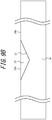
- the outer wall 34 may include a notch 37, as illustrated in FIG. 9B .
- the fixing member 4 passes through the notch 37 when the holding member 2 is aligned with the lens unit 3. Consequently, more of the projecting fixing member 4 projects outside of the outer wall 34 than in the above embodiment.
- the length of at least a portion of the outer wall 34 in the direction along the optical axis OX may be shorter than the length of the inner wall 33 in the direction along the optical axis OX.
- the groove 35 is disposed to surround the outer periphery of the opening, as illustrated in FIG. 1 .
- This configuration is not limiting, however.
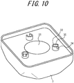
- the inner wall 33, the outer wall 34, and the groove 35 may be provided in at least a portion of the outer side of the opening, as illustrated in FIG. 10 .
- the amount of material for forming the inner wall 33 and the outer wall 34 can be reduced, thereby reducing costs and achieving a lightweight camera module 1.
- One or more filling holes 23 are provided in the holding member 2 in the above embodiment, but this configuration is not limiting. In other words, the filling holes 23 need not be provided in the holding member 2.
- the fixing member 4 joins to the lens unit 3 and the holding member 2 while in a state of being housed in the groove 35 and disposed on the edge 33a of the inner wall 33 and the edge 34a of the outer wall 34, thereby fixing the lens unit 3 and the holding member 2 together.
- the fixing member 4 in this case does not fit together with the holding member 2, but the uncured fixing member 4 need not be applied inside and around the filling holes 23, thereby simplifying the process for assembling the camera module 1.
Landscapes
- Physics & Mathematics (AREA)
- General Physics & Mathematics (AREA)
- Engineering & Computer Science (AREA)
- Multimedia (AREA)
- Signal Processing (AREA)
- Optics & Photonics (AREA)
- Studio Devices (AREA)
- Lens Barrels (AREA)
- Camera Bodies And Camera Details Or Accessories (AREA)
Abstract
Description
- The present application claims priority to and the benefit of Japanese Patent Application No.
2016-167418 filed August 29, 2016 - The present disclosure relates to a camera module, an imaging apparatus, and a vehicle.
- In a known camera module, a lens unit including a lens and a holding member holding an image sensor are fixed together using screws after positioning the lens and the image sensor. When the screws are tightened for fixing in this case, an external force due to rotation of the screws and sinking of members and the like acts on the lens unit or the holding member and may reduce the accuracy of the positional relationship between the lens and the image sensor. To prevent this, patent literature (PTL) 1, for example, discloses a method for fixing a lens unit and a holding member via a fixing member such as adhesive.
- PTL 1:
JP200828838A - When the lens unit and the holding member are adhered via a fixing member, however, the fixing member sometimes projects out from between the lens unit and the holding member when the position of the image sensor held by the holding member is adjusted with respect to the lens in the lens unit. The projecting fixing member may cause problems in the camera module. For example, if the fixing member projects out and attaches to the image sensor, defects occur in captured images. Furthermore, if the fixing member projects out, attaches to circuit elements held by the holding member, and then expands, the circuit elements may detach from the holding member.
- In light of these points, the present disclosure provides a camera module, an imaging apparatus, and a vehicle that can prevent a fixing member for fixing a lens unit and a holding member together from causing problems.
- A camera module of the present disclosure includes a lens unit, a holding member, and a fixing member. The lens unit includes a lens for causing light to enter an internal space. The holding member holds an image sensor for capturing an image formed by the light. The fixing member fixes the lens unit and the holding member. The fixing member is cured resin. The lens unit includes a groove at least partially housing the fixing member, and an opening of the groove faces the holding member. In a state such that the lens unit and the holding member are fixed, more of the fixing member is exposed to the outside of the lens unit than to an internal space surrounded by the lens unit and the holding member.
- An imaging apparatus of the present disclosure includes a camera module. The camera module includes a lens unit, a holding member, and a fixing member. The lens unit includes a lens for causing light to enter an internal space. The holding member holds an image sensor for capturing an image formed by the light. The fixing member fixes the lens unit and the holding member. The fixing member is cured resin. The lens unit includes a groove at least partially housing the fixing member, and an opening of the groove faces the holding member. In a state such that the lens unit and the holding member are fixed, more of the fixing member is exposed to the outside of the lens unit than to the internal space surrounded by the lens unit and the holding member.
- A vehicle of the present disclosure includes an imaging apparatus. The imaging apparatus includes a camera module. The camera module includes a lens unit, a holding member, and a fixing member. The lens unit includes a lens for causing light to enter an internal space. The holding member holds an image sensor for capturing an image formed by the light. The fixing member fixes the lens unit and the holding member. The fixing member is cured resin. The lens unit includes a groove at least partially housing the fixing member, and an opening of the groove faces the holding member. In a state such that the lens unit and the holding member are fixed, more of the fixing member is exposed to the outside of the lens unit than to the internal space surrounded by the lens unit and the holding member.
- An embodiment of the present disclosure can prevent a fixing member for fixing a lens unit and a holding member together from attaching to an image sensor, a circuit element, or the like and causing problems in a camera module.
- In the accompanying drawings:
-
FIG. 1 is an exploded perspective view of a camera module according to the present embodiment; -
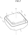
FIG. 2 is a perspective view of the camera module according to the present embodiment; -
FIG. 3 schematically illustrates a vehicle in which an imaging apparatus, provided with the camera module inFIG. 1 , is mounted; -
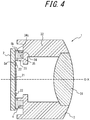
FIG. 4 is a cross-section of the camera module inFIG. 2 along the A-A line; -
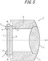
FIG. 5 is a cross-section of the camera module inFIG. 2 along the B-B line; -
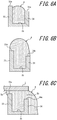
FIG. 6A illustrates a state in which a fixing member is filled in a groove; -
FIG. 6B illustrates a state in which an fixing member is applied to the groove so as to accumulate on the edge of the wall; -
FIG. 6C illustrates a state in which a holding member is aligned after the state inFIG. 6B ; -
FIG. 7 is an enlarged cross-section of a portion that joins to a holding member in a lens unit according to a first modification; -
FIG. 8 is an enlarged cross-section of a portion that joins to a holding member in a lens unit according to a second modification; -
FIG. 9A is an enlarged cross-section of a portion that joins to a holding member in a lens unit; -
FIG. 9B is a view ofFIG. 9A from the outer wall side; and -
FIG. 10 is a perspective view of a lens unit according to a fourth modification. - Various embodiments are described below in detail with reference to the drawings. The drawings referred to below are schematic illustrations, and the dimensional ratios and the like in the drawings do not necessarily match the actual dimensions.
- As illustrated in
FIG. 1 , acamera module 1 includes a holdingmember 2, alens unit 3, and a fixingmember 4 made by curing an adhesive or the like. Thelens unit 3 includes alens 31. Thelens 31 is fixed to thelens unit 3. When thecamera module 1 is in an assembled state, the holdingmember 2 and thelens unit 3 are fixed together, as illustrated inFIG. 2 . Thecamera module 1 is included in animaging apparatus 5, such as the one illustrated inFIG. 3 . Theimaging apparatus 5 is mounted in avehicle 6. Theimaging apparatus 5 mounted in thevehicle 6 captures images of the area ahead of thevehicle 6, for example. The imaging direction of theimaging apparatus 5 is not limited to being ahead of thevehicle 6. Theimaging apparatus 5 may capture images to the sides of or behind thevehicle 6 or may capture images of the inside of thevehicle 6. - The fixing
member 4 may be, but is not limited to, a resin such as epoxy, for example. The fixingmember 4 may be, but is not limited to, a cured resin such as a photocurable resin cured by irradiation with light (for example, ultraviolet (UV) light) or a thermosetting resin cured by application of heat. For example, the fixingmember 4 may be a UV and thermosetting fixing member cured by UV irradiation and heat. - As illustrated in
FIG. 4 , the holdingmember 2 is a member that fixes and holds animage sensor 21 andcircuit elements 22 such as resistors, capacitors, and transistors. Theimage sensor 21 captures an image formed by light entering the internal space of thelens unit 3. Theimage sensor 21 is fixed at the position, in the holdingmember 2, at which light passing through thelens 31 of thelens unit 3 forms an image. The position in the holdingmember 2 at which light forms an image is further inward than the position where the holdingmember 2 is joined to thelens unit 3, i.e. further inward than the position in the holdingmember 2 where the fixingmember 4 is disposed. Thecircuit elements 22 are fixed at positions on the holdingmember 2 where theimage sensor 21 is not disposed, further inward than the position where the holdingmember 2 is joined to thelens unit 3. - As illustrated in
FIG. 1 , one or more filling holes 23 are provided in the holdingmember 2. The filling holes 23 are provided to be opposite a portion of agroove 35, described below, when the holdingmember 2 is in a state of being fixed to thelens unit 3. Four fillingholes 23 are provided in the example inFIG. 1 . The number of fillingholes 23 is not, however, limited to four. - As illustrated in
FIG. 4 , thelens unit 3 includes thelens 31 for causing light to enter the internal space and alens barrel 32 that is open along an optical axis OX of thelens 31. Aninner wall 33, which is a first wall, and anouter wall 34, which is a second wall, are formed in thelens barrel 32. Thegroove 35 is formed in thelens barrel 32 by the surface of theinner wall 33 facing theouter wall 34, the surface of theouter wall 34 facing theinner wall 33, and the surface connecting these two surfaces. - The
lens 31 focuses incident light to form an image on theimage sensor 21. Thelens 31 may, for example, be a fisheye lens or an ultra-wide angle lens. Thelens 31 may be configured by a single lens or a plurality of lenses. - The opening of the
lens barrel 32 is the portion through which external light entering thelens 31 passes to reach theimage sensor 21. One or more other lenses forming an optical system along with thelens 31, or optical members such as various filters, can be arranged in the opening. - The
inner wall 33 is disposed in thelens unit 3 on the outside of the opening and protrudes towards the holdingmember 2. In other words, theinner wall 33 can have a surface parallel to the direction of the optical axis OX. The orientation of the surface of theinner wall 33 is not limited to this example and may be inclined relative to the optical axis OX. Theouter wall 34 is disposed on the opposite side of theinner wall 33 from the optical axis OX and protrudes towards the holdingmember 2. In other words, theouter wall 34 can have a surface parallel to the direction of the optical axis OX. The orientation of the surface of theouter wall 34 is not limited to this example and may be inclined relative to the optical axis OX. - The
inner wall 33 and theouter wall 34 are provided so that the region sandwiched between the holdingmember 2 and thegroove 35 opens more widely to the outside of the lens unit 3 (external space) than to the internal space that includes the optical axis OX of thelens 31. - Specifically, a gap Sb between the
outer wall 34 and the holdingmember 2 is larger than a gap Sa between theouter wall 34 and the holdingmember 2. In one example, the length of at least a portion of theouter wall 34 in the direction along the optical axis OX is shorter than the length of theinner wall 33 in the direction along the optical axis OX. Consequently, when the surface of the holdingmember 2 facing theouter wall 34 and theinner wall 33 is flat, the gap Sb between theouter wall 34 and the holdingmember 2 is larger than the gap Sa between theinner wall 33 and the holdingmember 2. - The
groove 35 at least partially houses the fixingmember 4. The opening of thegroove 35 is oriented towards the holdingmember 2. As illustrated inFIG. 1 , thegroove 35 may be disposed to surround the outer periphery of theimage sensor 21. - The fixing
member 4 is adhesive or the like that fixes thelens unit 3 and the holdingmember 2 together. When the holdingmember 2 and thelens unit 3 are to be joined, theuncured fixing member 4 is filled into thegroove 35 and is applied so as to accumulate on theedge 33a of theinner wall 33 and theedge 34a of theouter wall 34. After positioning thelens 31 and theimage sensor 21 to be in a state of alignment with each other, theuncured fixing member 4 is then filled into the filling holes 23 and is applied on the holdingmember 2 to accumulate around the filling holes 23 at the opposite side from the side facing thelens unit 3. In a state such that thelens unit 3 and the holdingmember 2 are fixed, more of the fixingmember 4 is exposed to the outside of thelens unit 3 than to the internal space surrounded by thelens unit 3 and the holdingmember 2. - Here, the "state of alignment" between the
lens 31 and theimage sensor 21 is a state in which thelens 31 and theimage sensor 21 have been aligned in each of the optical axis OX direction of thelens 31, a direction orthogonal to the optical axis OX, and a rotation direction around the direction orthogonal to the optical axis OX. - When the
uncured fixing member 4 that has been filled and applied in this way is cured, the fixingmember 4 joins to thelens unit 3 and the holdingmember 2 while in a state of being housed in thegroove 35 and disposed on theedge 33a of theinner wall 33 and theedge 34a of theouter wall 34, as illustrated inFIG. 4 . Furthermore, the fixingmember 4 is fitted with the holdingmember 2 in a state of being disposed around the filling holes 23, as illustrated inFIG. 5 . Here, "fitted" refers to two or more members fitting together to become integrated and restrict each other's movement. Accordingly, the holdingmember 2 and the lens unit are fixed together via the fixingmember 4. - When the
groove 35 is disposed to surround the outer periphery of theimage sensor 21 as described above, the fixingmember 4 forms a peripheral seal between thelens unit 3 and the holdingmember 2 along thegroove 35. - The filling and application of the fixing
member 4 when fixing the holdingmember 2 to thelens unit 3 are now described in greater detail. First, as illustrated inFIG. 6A , theuncured fixing member 4 is filled into thegroove 35. Once the fixingmember 4 is filled into thegroove 35, theuncured fixing member 4 is applied so as to accumulate on theedge 33a of theinner wall 33 and theedge 34a of theouter wall 34, as illustrated inFIG. 6B . In this state, thelens 31 and theimage sensor 21 are aligned, and the holdingmember 2 is aligned with thelens unit 3, as illustrated inFIG. 6C . A portion of theuncured fixing member 4 that had accumulated on theedges outer wall 34 through the gap Sb between theouter wall 34 and the holdingmember 2. The gap Sb is larger than the gap Sa. Consequently, most of theuncured fixing member 4 is extruded to the external space through the gap Sb. The amount of uncured fixingmember 4 that is extruded to the internal space through the gap Sa is less than when the gap Sa and the gap Sb are the same size. - In this way, even if the
uncured fixing member 4 projects out from between thelens unit 3 and the holdingmember 2 when the position of the holdingmember 2 is adjusted relative to thelens 31 of thelens unit 3, the above embodiment can reduce problems caused by the projecting fixingmember 4. Specifically, most of the fixingmember 4 projects to the outside of thegroove 35 by passing not through the gap Sa, but rather through the larger gap Sb. Consequently, little of the fixingmember 4 projects to the inside of thegroove 35, which can reduce attachment of the fixingmember 4 to theimage sensor 21 or to thecircuit elements 22 held by the holdingmember 2. Problems in thecamera module 1 due to the fixingmember 4 can therefore be reduced. - In the present embodiment, the
inner wall 33, theouter wall 34, and thegroove 35 are disposed to surround the outer periphery of the opening, i.e. to form a closed curve when viewed from the optical axis OX direction. The fixingmember 4 is disposed between (i) the inside of thegroove 35, theedge 33a of theinner wall 33, and theedge 34a of theouter wall 34 and (ii) the holdingmember 2. The likelihood of dirt, dust, or the like entering the internal space from outside thelens unit 3 can therefore be reduced. Accordingly, the attachment of dirt, dust, or the like to theimage sensor 21, thecircuit elements 22, thelens 31, and the like can be reduced, allowing a reduction in problems in thecamera module 1. - Since the
lens unit 3 and the holdingmember 2 are joined and fit to the fixingmember 4 in the present embodiment, thelens unit 3 and the holdingmember 2 can prevent each other from moving in the optical axis OX direction and from moving in the rotation direction around the direction orthogonal to the optical axis OX. Therefore, the distance between thelens 31 and theimage sensor 21 is maintained, and the state of alignment in the optical axis OX direction and the rotation direction around the direction orthogonal to the optical axis OX is maintained. Furthermore, movement in the direction orthogonal to the optical axis OX direction and movement in the rotation direction around the optical axis OX direction can be prevented. The state of alignment in the direction orthogonal to the optical axis OX direction and the rotation direction around the optical axis OX direction can therefore be maintained. - The
lens unit 3 and the holdingmember 2 in the present embodiment are aligned and then fixed by photocuring and/or thermally curing the fixingmember 4. Misalignment due to an external force can therefore be prevented. Furthermore, members such as screws need not be used, allowing a high degree of freedom for designs without space for such members. - The above embodiments and examples have been described as representative examples, but it will be apparent to one of ordinary skill in the art that numerous modifications and replacements may be made within the spirit and scope of the present disclosure. Therefore, the present disclosure should not be interpreted as being restricted to the above embodiments and examples. A variety of changes or modifications may be made without departing from the scope of the appended claims.
- In the above embodiment, the length of at least a portion of the
outer wall 34 in the direction along the optical axis OX is shorter than the length of theinner wall 33 in the direction along the optical axis OX, but this example is not limiting. For example, theouter wall 34 may include a through-hole 36 penetrating to the external space, as illustrated inFIG. 7 . The size, shape, and number of through-holes 36 may be chosen freely. In this case, the through-hole 36 and the gap Sbl between theouter wall 34 and the holdingmember 2 are the portion that opens to the external space in the region sandwiched between the holdingmember 2 and thegroove 35. In this way, less of the fixingmember 4 projects into the internal space of thegroove 35 than into the external space. Attachment or the like of the projecting fixingmember 4 to theimage sensor 21 or to thecircuit elements 22 held by the holdingmember 2 can therefore be reduced. - The
edge 34a of theouter wall 34 in the above embodiment is illustrated inFIGS. 6A, 6B, and 6C as a surface substantially perpendicular to the optical axis OX, but this configuration is not limiting. For example, as illustrated inFIG. 8 , theedge 34a may have a tapered shape inclined to separate from the holdingmember 2 with increased distance from the optical axis OX. In this case, the fixingmember 4 projects out along the tapered surface when the holdingmember 2 is aligned with thelens unit 3. Consequently, more of the projecting fixingmember 4 projects outside of theouter wall 34 than in the above embodiment. Even less of the fixingmember 4 therefore passes through the gap Sa and projects into the internal space of thelens unit 3. Accordingly, little of the fixingmember 4 projects into thegroove 35, and attachment to theimage sensor 21, thecircuit elements 22, and the like can be even further reduced. - In the above embodiment, the length of at least a portion of the
outer wall 34 in the direction along the optical axis OX is set to be shorter than the length of theinner wall 33 in the direction along the optical axis OX, but this example is not limiting. For example, the length of at least a portion of theouter wall 34 in the direction along the optical axis OX may be substantially equal to the length of theinner wall 33 in the direction along the optical axis OX, as illustrated inFIG. 9A . Theouter wall 34 may include anotch 37, as illustrated inFIG. 9B . The fixingmember 4 passes through thenotch 37 when the holdingmember 2 is aligned with thelens unit 3. Consequently, more of the projecting fixingmember 4 projects outside of theouter wall 34 than in the above embodiment. Even less of the fixingmember 4 therefore projects into the internal space of thelens unit 3. Hence, attachment to theimage sensor 21, the circuit elements, and the like can be even further reduced. In this example, the length of at least a portion of theouter wall 34 in the direction along the optical axis OX may be shorter than the length of theinner wall 33 in the direction along the optical axis OX. - In the above embodiment, the
groove 35 is disposed to surround the outer periphery of the opening, as illustrated inFIG. 1 . This configuration is not limiting, however. Theinner wall 33, theouter wall 34, and thegroove 35 may be provided in at least a portion of the outer side of the opening, as illustrated inFIG. 10 . In this case, the amount of material for forming theinner wall 33 and theouter wall 34 can be reduced, thereby reducing costs and achieving alightweight camera module 1. - One or more filling holes 23 are provided in the holding
member 2 in the above embodiment, but this configuration is not limiting. In other words, the filling holes 23 need not be provided in the holdingmember 2. In this case, the fixingmember 4 joins to thelens unit 3 and the holdingmember 2 while in a state of being housed in thegroove 35 and disposed on theedge 33a of theinner wall 33 and theedge 34a of theouter wall 34, thereby fixing thelens unit 3 and the holdingmember 2 together. The fixingmember 4 in this case does not fit together with the holdingmember 2, but theuncured fixing member 4 need not be applied inside and around the filling holes 23, thereby simplifying the process for assembling thecamera module 1. -
- 1
- Camera module
- 2
- Holding member
- 3
- Lens unit
- 4
- Fixing member
- 5
- Imaging apparatus
- 6
- Vehicle
- 21
- Image sensor
- 22
- Circuit element
- 23
- Filling hole
- 31
- Lens
- 32
- Lens barrel
- 33
- Inner wall
- 34
- Outer wall
- 33a, 34a
- Edge
- 35
- Groove
- 36
- Through-hole
- 37
- Notch
Claims (7)
- A camera module comprising:a lens unit including a lens;a holding member configured to hold an image sensor for capturing an image formed by light; anda fixing member made of cured resin and configured to fix the lens unit and the holding member;wherein the lens unit includes a groove at least partially housing the fixing member, an opening of the groove faces the holding member, and in a state such that the lens unit and the holding member are fixed, more of the fixing member is exposed to an outside of the lens unit than to an internal space surrounded by the lens unit and the holding member.
- The camera module of claim 1, wherein the lens unit includes a first wall on the internal space side of the groove and a second wall on an external space side of the groove, and a length of at least a portion of the second wall in an optical axis direction is shorter than a length of the first wall in the optical axis direction.
- The camera module of claim 2, wherein an edge of the second wall on the holding member side has a tapered shape inclined to separate from the holding member with increased distance from the optical axis.
- The camera module of any one of claims 1 to 3, wherein the groove includes a through-hole penetrating to an external space.
- The camera module of any one of claims 1 to 4, wherein the groove is disposed to surround an outer periphery of the image sensor, and the fixing member forms a peripheral seal between the lens unit and the holding member along the groove.
- An imaging apparatus comprising:a camera module;wherein the camera module comprises:a lens unit including a lens configured to cause light to enter an internal space;a holding member configured to hold an image sensor for capturing an image formed by the light; anda fixing member made of cured resin and configured to fix the lens unit and the holding member;wherein the lens unit includes a groove at least partially housing the fixing member, an opening of the groove faces the holding member, and in a state such that the lens unit and the holding member are fixed, more of the fixing member is exposed to an outside of the lens unit than to the internal space surrounded by the lens unit and the holding member.
- A vehicle comprising:an imaging apparatus comprising a camera module;wherein the camera module comprises:a lens unit including a lens configured to cause light to enter an internal space;a holding member configured to hold an image sensor for capturing an image formed by the light; anda fixing member made of cured resin and configured to fix the lens unit and the holding member;wherein the lens unit includes a groove at least partially housing the fixing member, an opening of the groove faces the holding member, and in a state such that the lens unit and the holding member are fixed, more of the fixing member is exposed to an outside of the lens unit than to the internal space surrounded by the lens unit and the holding member.
Applications Claiming Priority (2)
| Application Number | Priority Date | Filing Date | Title |
|---|---|---|---|
| JP2016167418 | 2016-08-29 | ||
| PCT/JP2017/029745 WO2018043172A1 (en) | 2016-08-29 | 2017-08-21 | Camera module, imaging device, and movable body |
Publications (3)
| Publication Number | Publication Date |
|---|---|
| EP3505984A1 true EP3505984A1 (en) | 2019-07-03 |
| EP3505984A4 EP3505984A4 (en) | 2020-05-27 |
| EP3505984B1 EP3505984B1 (en) | 2022-04-27 |
Family
ID=61301630
Family Applications (1)
| Application Number | Title | Priority Date | Filing Date |
|---|---|---|---|
| EP17846180.2A Active EP3505984B1 (en) | 2016-08-29 | 2017-08-21 | Camera module, imaging device, and movable body |
Country Status (5)
| Country | Link |
|---|---|
| US (1) | US10715710B2 (en) |
| EP (1) | EP3505984B1 (en) |
| JP (1) | JP6748721B2 (en) |
| CN (1) | CN109643004B (en) |
| WO (1) | WO2018043172A1 (en) |
Families Citing this family (6)
| Publication number | Priority date | Publication date | Assignee | Title |
|---|---|---|---|---|
| EP4236338B1 (en) | 2017-05-22 | 2025-12-31 | Lg Innotek Co., Ltd. | LENS DRIVE DEVICE, CAMERA MODULE AND OPTICAL DEVICE |
| DE102018121367A1 (en) * | 2018-08-31 | 2020-03-05 | Carl Zeiss Ag | Optical system for use in an underwater environment |
| ES2798182B2 (en) * | 2019-06-06 | 2021-04-22 | Univ Pablo De Olavide | System for neurostimulation |
| CN210007739U (en) * | 2019-06-28 | 2020-01-31 | 三赢科技(深圳)有限公司 | Lens module and electronic device |
| DE102020108771A1 (en) | 2020-03-30 | 2021-09-30 | Connaught Electronics Ltd. | Method for assembling a camera for a vehicle, pre-assembly module for a camera and camera |
| CN113438394A (en) * | 2021-06-16 | 2021-09-24 | 蔚来汽车科技(安徽)有限公司 | Front cover of vehicle-mounted camera, vehicle-mounted camera device and vehicle |
Family Cites Families (15)
| Publication number | Priority date | Publication date | Assignee | Title |
|---|---|---|---|---|
| JP2000147345A (en) * | 1998-11-16 | 2000-05-26 | Sony Corp | Optical axis correction apparatus, optical axis correction apparatus manufacturing apparatus, and optical axis correction apparatus manufacturing method |
| JP2003289457A (en) * | 2002-01-22 | 2003-10-10 | Casio Comput Co Ltd | Imaging device |
| JP2005236754A (en) * | 2004-02-20 | 2005-09-02 | Toko Inc | Image sensor module |
| JP2006086672A (en) * | 2004-09-15 | 2006-03-30 | Nidec Copal Corp | Imaging module |
| JP2007110594A (en) * | 2005-10-17 | 2007-04-26 | Hitachi Maxell Ltd | The camera module |
| JP2008028838A (en) | 2006-07-24 | 2008-02-07 | Sharp Corp | Camera module and manufacturing method thereof |
| KR101316408B1 (en) * | 2006-08-29 | 2013-10-08 | 엘지이노텍 주식회사 | Detection monitoring apparatus and method |
| KR100832072B1 (en) * | 2006-10-27 | 2008-05-27 | 삼성전기주식회사 | Camera module |
| CN100561280C (en) * | 2007-05-30 | 2009-11-18 | 鸿富锦精密工业(深圳)有限公司 | Camera module and manufacturing method thereof |
| US20090079863A1 (en) * | 2007-09-20 | 2009-03-26 | Susumu Aoki | Camera module, manufacturing method of imaging apparatus and hot melt molding method |
| DE102009055083B4 (en) * | 2009-12-21 | 2013-12-05 | Fraunhofer-Gesellschaft zur Förderung der angewandten Forschung e.V. | Optical layer stack and method for its production |
| JP2012002979A (en) * | 2010-06-16 | 2012-01-05 | Panasonic Corp | Lens barrel, imaging device and portable terminal apparatus |
| JP2014093632A (en) * | 2012-11-02 | 2014-05-19 | Konica Minolta Inc | Camera module manufacturing method, camera module, and portable terminal |
| TW201445857A (en) * | 2013-05-30 | 2014-12-01 | Hon Hai Prec Ind Co Ltd | Voice coil motor and lens module |
| CN104749858A (en) * | 2015-03-12 | 2015-07-01 | 南昌欧菲光电技术有限公司 | Camera module bracket and camera module |
-
2017
- 2017-08-21 JP JP2018537134A patent/JP6748721B2/en active Active
- 2017-08-21 CN CN201780052925.2A patent/CN109643004B/en active Active
- 2017-08-21 WO PCT/JP2017/029745 patent/WO2018043172A1/en not_active Ceased
- 2017-08-21 EP EP17846180.2A patent/EP3505984B1/en active Active
- 2017-08-21 US US16/329,337 patent/US10715710B2/en active Active
Also Published As
| Publication number | Publication date |
|---|---|
| EP3505984B1 (en) | 2022-04-27 |
| US10715710B2 (en) | 2020-07-14 |
| JP6748721B2 (en) | 2020-09-02 |
| EP3505984A4 (en) | 2020-05-27 |
| CN109643004B (en) | 2021-07-20 |
| JPWO2018043172A1 (en) | 2019-06-24 |
| US20190222729A1 (en) | 2019-07-18 |
| WO2018043172A1 (en) | 2018-03-08 |
| CN109643004A (en) | 2019-04-16 |
Similar Documents
| Publication | Publication Date | Title |
|---|---|---|
| US10715710B2 (en) | Camera module, imaging apparatus, and vehicle | |
| JP5601000B2 (en) | Imaging device | |
| JP6578279B2 (en) | IMAGING DEVICE, OPTICAL DEVICE, ELECTRONIC DEVICE, VEHICLE, AND IMAGING DEVICE MANUFACTURING METHOD | |
| US10530978B2 (en) | Integrated image sensor and lens assembly | |
| US8570672B2 (en) | Lens module | |
| US9028159B2 (en) | Camera module with threadless lens barrel engagement design | |
| US20090244735A1 (en) | Lens assembly and imaging apparatus | |
| KR102172637B1 (en) | Dual camera module | |
| JP5871534B2 (en) | Imaging device | |
| US10341541B2 (en) | Integrated sensor and lens assembly with post-tuning optical alignment | |
| US8094200B2 (en) | Lens apparatus and imaging apparatus | |
| US20230217093A1 (en) | Image sensor module and camera module having the same | |
| US10562467B2 (en) | Bonding structure, imaging apparatus, and on-vehicle camera | |
| CN101523893B (en) | Imaging device and method of producing the same | |
| CN101893746B (en) | Lens barrel | |
| US20190212519A1 (en) | Optical device | |
| JP6645689B2 (en) | Optical equipment | |
| CN110892707B (en) | Image capturing apparatus | |
| KR20170130836A (en) | Camera module | |
| JP6444613B2 (en) | Lens barrel and imaging device | |
| JP7296826B2 (en) | Lens unit and camera module | |
| US20160018622A1 (en) | Optical apparatus | |
| CN110622053A (en) | Lens barrel | |
| JP2007147729A (en) | Camera module | |
| JP6619148B2 (en) | Lens barrel and camera |
Legal Events
| Date | Code | Title | Description |
|---|---|---|---|
| STAA | Information on the status of an ep patent application or granted ep patent |
Free format text: STATUS: THE INTERNATIONAL PUBLICATION HAS BEEN MADE |
|
| PUAI | Public reference made under article 153(3) epc to a published international application that has entered the european phase |
Free format text: ORIGINAL CODE: 0009012 |
|
| STAA | Information on the status of an ep patent application or granted ep patent |
Free format text: STATUS: REQUEST FOR EXAMINATION WAS MADE |
|
| 17P | Request for examination filed |
Effective date: 20190228 |
|
| AK | Designated contracting states |
Kind code of ref document: A1 Designated state(s): AL AT BE BG CH CY CZ DE DK EE ES FI FR GB GR HR HU IE IS IT LI LT LU LV MC MK MT NL NO PL PT RO RS SE SI SK SM TR |
|
| AX | Request for extension of the european patent |
Extension state: BA ME |
|
| DAV | Request for validation of the european patent (deleted) | ||
| DAX | Request for extension of the european patent (deleted) | ||
| A4 | Supplementary search report drawn up and despatched |
Effective date: 20200428 |
|
| RIC1 | Information provided on ipc code assigned before grant |
Ipc: H04N 5/225 20060101ALI20200421BHEP Ipc: G03B 17/02 20060101ALI20200421BHEP Ipc: G02B 7/02 20060101AFI20200421BHEP |
|
| GRAP | Despatch of communication of intention to grant a patent |
Free format text: ORIGINAL CODE: EPIDOSNIGR1 |
|
| STAA | Information on the status of an ep patent application or granted ep patent |
Free format text: STATUS: GRANT OF PATENT IS INTENDED |
|
| INTG | Intention to grant announced |
Effective date: 20211124 |
|
| RIN1 | Information on inventor provided before grant (corrected) |
Inventor name: YOSHIKAWA, ATSUSHI |
|
| GRAS | Grant fee paid |
Free format text: ORIGINAL CODE: EPIDOSNIGR3 |
|
| GRAA | (expected) grant |
Free format text: ORIGINAL CODE: 0009210 |
|
| STAA | Information on the status of an ep patent application or granted ep patent |
Free format text: STATUS: THE PATENT HAS BEEN GRANTED |
|
| AK | Designated contracting states |
Kind code of ref document: B1 Designated state(s): AL AT BE BG CH CY CZ DE DK EE ES FI FR GB GR HR HU IE IS IT LI LT LU LV MC MK MT NL NO PL PT RO RS SE SI SK SM TR |
|
| REG | Reference to a national code |
Ref country code: GB Ref legal event code: FG4D |
|
| REG | Reference to a national code |
Ref country code: CH Ref legal event code: EP |
|
| REG | Reference to a national code |
Ref country code: DE Ref legal event code: R096 Ref document number: 602017056678 Country of ref document: DE |
|
| REG | Reference to a national code |
Ref country code: AT Ref legal event code: REF Ref document number: 1487379 Country of ref document: AT Kind code of ref document: T Effective date: 20220515 |
|
| REG | Reference to a national code |
Ref country code: IE Ref legal event code: FG4D |
|
| REG | Reference to a national code |
Ref country code: LT Ref legal event code: MG9D |
|
| REG | Reference to a national code |
Ref country code: NL Ref legal event code: MP Effective date: 20220427 |
|
| REG | Reference to a national code |
Ref country code: AT Ref legal event code: MK05 Ref document number: 1487379 Country of ref document: AT Kind code of ref document: T Effective date: 20220427 |
|
| PG25 | Lapsed in a contracting state [announced via postgrant information from national office to epo] |
Ref country code: NL Free format text: LAPSE BECAUSE OF FAILURE TO SUBMIT A TRANSLATION OF THE DESCRIPTION OR TO PAY THE FEE WITHIN THE PRESCRIBED TIME-LIMIT Effective date: 20220427 |
|
| PG25 | Lapsed in a contracting state [announced via postgrant information from national office to epo] |
Ref country code: SE Free format text: LAPSE BECAUSE OF FAILURE TO SUBMIT A TRANSLATION OF THE DESCRIPTION OR TO PAY THE FEE WITHIN THE PRESCRIBED TIME-LIMIT Effective date: 20220427 Ref country code: PT Free format text: LAPSE BECAUSE OF FAILURE TO SUBMIT A TRANSLATION OF THE DESCRIPTION OR TO PAY THE FEE WITHIN THE PRESCRIBED TIME-LIMIT Effective date: 20220829 Ref country code: NO Free format text: LAPSE BECAUSE OF FAILURE TO SUBMIT A TRANSLATION OF THE DESCRIPTION OR TO PAY THE FEE WITHIN THE PRESCRIBED TIME-LIMIT Effective date: 20220727 Ref country code: LT Free format text: LAPSE BECAUSE OF FAILURE TO SUBMIT A TRANSLATION OF THE DESCRIPTION OR TO PAY THE FEE WITHIN THE PRESCRIBED TIME-LIMIT Effective date: 20220427 Ref country code: HR Free format text: LAPSE BECAUSE OF FAILURE TO SUBMIT A TRANSLATION OF THE DESCRIPTION OR TO PAY THE FEE WITHIN THE PRESCRIBED TIME-LIMIT Effective date: 20220427 Ref country code: GR Free format text: LAPSE BECAUSE OF FAILURE TO SUBMIT A TRANSLATION OF THE DESCRIPTION OR TO PAY THE FEE WITHIN THE PRESCRIBED TIME-LIMIT Effective date: 20220728 Ref country code: FI Free format text: LAPSE BECAUSE OF FAILURE TO SUBMIT A TRANSLATION OF THE DESCRIPTION OR TO PAY THE FEE WITHIN THE PRESCRIBED TIME-LIMIT Effective date: 20220427 Ref country code: ES Free format text: LAPSE BECAUSE OF FAILURE TO SUBMIT A TRANSLATION OF THE DESCRIPTION OR TO PAY THE FEE WITHIN THE PRESCRIBED TIME-LIMIT Effective date: 20220427 Ref country code: BG Free format text: LAPSE BECAUSE OF FAILURE TO SUBMIT A TRANSLATION OF THE DESCRIPTION OR TO PAY THE FEE WITHIN THE PRESCRIBED TIME-LIMIT Effective date: 20220727 Ref country code: AT Free format text: LAPSE BECAUSE OF FAILURE TO SUBMIT A TRANSLATION OF THE DESCRIPTION OR TO PAY THE FEE WITHIN THE PRESCRIBED TIME-LIMIT Effective date: 20220427 |
|
| PG25 | Lapsed in a contracting state [announced via postgrant information from national office to epo] |
Ref country code: RS Free format text: LAPSE BECAUSE OF FAILURE TO SUBMIT A TRANSLATION OF THE DESCRIPTION OR TO PAY THE FEE WITHIN THE PRESCRIBED TIME-LIMIT Effective date: 20220427 Ref country code: PL Free format text: LAPSE BECAUSE OF FAILURE TO SUBMIT A TRANSLATION OF THE DESCRIPTION OR TO PAY THE FEE WITHIN THE PRESCRIBED TIME-LIMIT Effective date: 20220427 Ref country code: LV Free format text: LAPSE BECAUSE OF FAILURE TO SUBMIT A TRANSLATION OF THE DESCRIPTION OR TO PAY THE FEE WITHIN THE PRESCRIBED TIME-LIMIT Effective date: 20220427 Ref country code: IS Free format text: LAPSE BECAUSE OF FAILURE TO SUBMIT A TRANSLATION OF THE DESCRIPTION OR TO PAY THE FEE WITHIN THE PRESCRIBED TIME-LIMIT Effective date: 20220827 |
|
| REG | Reference to a national code |
Ref country code: DE Ref legal event code: R097 Ref document number: 602017056678 Country of ref document: DE |
|
| PG25 | Lapsed in a contracting state [announced via postgrant information from national office to epo] |
Ref country code: SM Free format text: LAPSE BECAUSE OF FAILURE TO SUBMIT A TRANSLATION OF THE DESCRIPTION OR TO PAY THE FEE WITHIN THE PRESCRIBED TIME-LIMIT Effective date: 20220427 Ref country code: SK Free format text: LAPSE BECAUSE OF FAILURE TO SUBMIT A TRANSLATION OF THE DESCRIPTION OR TO PAY THE FEE WITHIN THE PRESCRIBED TIME-LIMIT Effective date: 20220427 Ref country code: RO Free format text: LAPSE BECAUSE OF FAILURE TO SUBMIT A TRANSLATION OF THE DESCRIPTION OR TO PAY THE FEE WITHIN THE PRESCRIBED TIME-LIMIT Effective date: 20220427 Ref country code: EE Free format text: LAPSE BECAUSE OF FAILURE TO SUBMIT A TRANSLATION OF THE DESCRIPTION OR TO PAY THE FEE WITHIN THE PRESCRIBED TIME-LIMIT Effective date: 20220427 Ref country code: DK Free format text: LAPSE BECAUSE OF FAILURE TO SUBMIT A TRANSLATION OF THE DESCRIPTION OR TO PAY THE FEE WITHIN THE PRESCRIBED TIME-LIMIT Effective date: 20220427 Ref country code: CZ Free format text: LAPSE BECAUSE OF FAILURE TO SUBMIT A TRANSLATION OF THE DESCRIPTION OR TO PAY THE FEE WITHIN THE PRESCRIBED TIME-LIMIT Effective date: 20220427 |
|
| PLBE | No opposition filed within time limit |
Free format text: ORIGINAL CODE: 0009261 |
|
| STAA | Information on the status of an ep patent application or granted ep patent |
Free format text: STATUS: NO OPPOSITION FILED WITHIN TIME LIMIT |
|
| PG25 | Lapsed in a contracting state [announced via postgrant information from national office to epo] |
Ref country code: MC Free format text: LAPSE BECAUSE OF FAILURE TO SUBMIT A TRANSLATION OF THE DESCRIPTION OR TO PAY THE FEE WITHIN THE PRESCRIBED TIME-LIMIT Effective date: 20220427 Ref country code: AL Free format text: LAPSE BECAUSE OF FAILURE TO SUBMIT A TRANSLATION OF THE DESCRIPTION OR TO PAY THE FEE WITHIN THE PRESCRIBED TIME-LIMIT Effective date: 20220427 |
|
| REG | Reference to a national code |
Ref country code: CH Ref legal event code: PL |
|
| 26N | No opposition filed |
Effective date: 20230130 |
|
| PG25 | Lapsed in a contracting state [announced via postgrant information from national office to epo] |
Ref country code: LU Free format text: LAPSE BECAUSE OF NON-PAYMENT OF DUE FEES Effective date: 20220821 Ref country code: LI Free format text: LAPSE BECAUSE OF NON-PAYMENT OF DUE FEES Effective date: 20220831 Ref country code: CH Free format text: LAPSE BECAUSE OF NON-PAYMENT OF DUE FEES Effective date: 20220831 |
|
| REG | Reference to a national code |
Ref country code: BE Ref legal event code: MM Effective date: 20220831 |
|
| PG25 | Lapsed in a contracting state [announced via postgrant information from national office to epo] |
Ref country code: SI Free format text: LAPSE BECAUSE OF FAILURE TO SUBMIT A TRANSLATION OF THE DESCRIPTION OR TO PAY THE FEE WITHIN THE PRESCRIBED TIME-LIMIT Effective date: 20220427 |
|
| P01 | Opt-out of the competence of the unified patent court (upc) registered |
Effective date: 20230505 |
|
| PG25 | Lapsed in a contracting state [announced via postgrant information from national office to epo] |
Ref country code: IE Free format text: LAPSE BECAUSE OF NON-PAYMENT OF DUE FEES Effective date: 20220821 |
|
| PG25 | Lapsed in a contracting state [announced via postgrant information from national office to epo] |
Ref country code: BE Free format text: LAPSE BECAUSE OF NON-PAYMENT OF DUE FEES Effective date: 20220831 |
|
| PG25 | Lapsed in a contracting state [announced via postgrant information from national office to epo] |
Ref country code: IT Free format text: LAPSE BECAUSE OF FAILURE TO SUBMIT A TRANSLATION OF THE DESCRIPTION OR TO PAY THE FEE WITHIN THE PRESCRIBED TIME-LIMIT Effective date: 20220427 |
|
| PG25 | Lapsed in a contracting state [announced via postgrant information from national office to epo] |
Ref country code: HU Free format text: LAPSE BECAUSE OF FAILURE TO SUBMIT A TRANSLATION OF THE DESCRIPTION OR TO PAY THE FEE WITHIN THE PRESCRIBED TIME-LIMIT; INVALID AB INITIO Effective date: 20170821 |
|
| PG25 | Lapsed in a contracting state [announced via postgrant information from national office to epo] |
Ref country code: CY Free format text: LAPSE BECAUSE OF FAILURE TO SUBMIT A TRANSLATION OF THE DESCRIPTION OR TO PAY THE FEE WITHIN THE PRESCRIBED TIME-LIMIT Effective date: 20220427 |
|
| PG25 | Lapsed in a contracting state [announced via postgrant information from national office to epo] |
Ref country code: MK Free format text: LAPSE BECAUSE OF FAILURE TO SUBMIT A TRANSLATION OF THE DESCRIPTION OR TO PAY THE FEE WITHIN THE PRESCRIBED TIME-LIMIT Effective date: 20220427 |
|
| PG25 | Lapsed in a contracting state [announced via postgrant information from national office to epo] |
Ref country code: TR Free format text: LAPSE BECAUSE OF FAILURE TO SUBMIT A TRANSLATION OF THE DESCRIPTION OR TO PAY THE FEE WITHIN THE PRESCRIBED TIME-LIMIT Effective date: 20220427 |
|
| PGFP | Annual fee paid to national office [announced via postgrant information from national office to epo] |
Ref country code: GB Payment date: 20240627 Year of fee payment: 8 |
|
| PG25 | Lapsed in a contracting state [announced via postgrant information from national office to epo] |
Ref country code: MT Free format text: LAPSE BECAUSE OF FAILURE TO SUBMIT A TRANSLATION OF THE DESCRIPTION OR TO PAY THE FEE WITHIN THE PRESCRIBED TIME-LIMIT Effective date: 20220427 |
|
| PGFP | Annual fee paid to national office [announced via postgrant information from national office to epo] |
Ref country code: DE Payment date: 20240702 Year of fee payment: 8 |
|
| PGFP | Annual fee paid to national office [announced via postgrant information from national office to epo] |
Ref country code: FR Payment date: 20240702 Year of fee payment: 8 |
|
| PG25 | Lapsed in a contracting state [announced via postgrant information from national office to epo] |
Ref country code: BG Free format text: LAPSE BECAUSE OF FAILURE TO SUBMIT A TRANSLATION OF THE DESCRIPTION OR TO PAY THE FEE WITHIN THE PRESCRIBED TIME-LIMIT Effective date: 20220427 |
|
| PG25 | Lapsed in a contracting state [announced via postgrant information from national office to epo] |
Ref country code: BG Free format text: LAPSE BECAUSE OF FAILURE TO SUBMIT A TRANSLATION OF THE DESCRIPTION OR TO PAY THE FEE WITHIN THE PRESCRIBED TIME-LIMIT Effective date: 20220427 |
|
| REG | Reference to a national code |
Ref country code: DE Ref legal event code: R119 Ref document number: 602017056678 Country of ref document: DE |