EP3505842A1 - Retrofitting r-410a hvac products to handle flammable refrigerants - Google Patents
Retrofitting r-410a hvac products to handle flammable refrigerants Download PDFInfo
- Publication number
- EP3505842A1 EP3505842A1 EP18213237.3A EP18213237A EP3505842A1 EP 3505842 A1 EP3505842 A1 EP 3505842A1 EP 18213237 A EP18213237 A EP 18213237A EP 3505842 A1 EP3505842 A1 EP 3505842A1
- Authority
- EP
- European Patent Office
- Prior art keywords
- refrigerant
- hvacr
- hvacr system
- disposed
- enclosure
- Prior art date
- Legal status (The legal status is an assumption and is not a legal conclusion. Google has not performed a legal analysis and makes no representation as to the accuracy of the status listed.)
- Granted
Links
Images




Classifications
-
- F—MECHANICAL ENGINEERING; LIGHTING; HEATING; WEAPONS; BLASTING
- F24—HEATING; RANGES; VENTILATING
- F24F—AIR-CONDITIONING; AIR-HUMIDIFICATION; VENTILATION; USE OF AIR CURRENTS FOR SCREENING
- F24F1/00—Room units for air-conditioning, e.g. separate or self-contained units or units receiving primary air from a central station
- F24F1/06—Separate outdoor units, e.g. outdoor unit to be linked to a separate room comprising a compressor and a heat exchanger
- F24F1/26—Refrigerant piping
- F24F1/32—Refrigerant piping for connecting the separate outdoor units to indoor units
-
- F—MECHANICAL ENGINEERING; LIGHTING; HEATING; WEAPONS; BLASTING
- F24—HEATING; RANGES; VENTILATING
- F24F—AIR-CONDITIONING; AIR-HUMIDIFICATION; VENTILATION; USE OF AIR CURRENTS FOR SCREENING
- F24F11/00—Control or safety arrangements
- F24F11/30—Control or safety arrangements for purposes related to the operation of the system, e.g. for safety or monitoring
- F24F11/32—Responding to malfunctions or emergencies
- F24F11/36—Responding to malfunctions or emergencies to leakage of heat-exchange fluid
-
- F—MECHANICAL ENGINEERING; LIGHTING; HEATING; WEAPONS; BLASTING
- F24—HEATING; RANGES; VENTILATING
- F24F—AIR-CONDITIONING; AIR-HUMIDIFICATION; VENTILATION; USE OF AIR CURRENTS FOR SCREENING
- F24F11/00—Control or safety arrangements
- F24F11/50—Control or safety arrangements characterised by user interfaces or communication
- F24F11/52—Indication arrangements, e.g. displays
- F24F11/526—Indication arrangements, e.g. displays giving audible indications
-
- F—MECHANICAL ENGINEERING; LIGHTING; HEATING; WEAPONS; BLASTING
- F24—HEATING; RANGES; VENTILATING
- F24F—AIR-CONDITIONING; AIR-HUMIDIFICATION; VENTILATION; USE OF AIR CURRENTS FOR SCREENING
- F24F7/00—Ventilation
- F24F7/007—Ventilation with forced flow
- F24F7/013—Ventilation with forced flow using wall or window fans, displacing air through the wall or window
-
- F—MECHANICAL ENGINEERING; LIGHTING; HEATING; WEAPONS; BLASTING
- F25—REFRIGERATION OR COOLING; COMBINED HEATING AND REFRIGERATION SYSTEMS; HEAT PUMP SYSTEMS; MANUFACTURE OR STORAGE OF ICE; LIQUEFACTION SOLIDIFICATION OF GASES
- F25B—REFRIGERATION MACHINES, PLANTS OR SYSTEMS; COMBINED HEATING AND REFRIGERATION SYSTEMS; HEAT PUMP SYSTEMS
- F25B45/00—Arrangements for charging or discharging refrigerant
-
- F—MECHANICAL ENGINEERING; LIGHTING; HEATING; WEAPONS; BLASTING
- F24—HEATING; RANGES; VENTILATING
- F24F—AIR-CONDITIONING; AIR-HUMIDIFICATION; VENTILATION; USE OF AIR CURRENTS FOR SCREENING
- F24F2110/00—Control inputs relating to air properties
- F24F2110/50—Air quality properties
- F24F2110/65—Concentration of specific substances or contaminants
- F24F2110/76—Oxygen
-
- F—MECHANICAL ENGINEERING; LIGHTING; HEATING; WEAPONS; BLASTING
- F25—REFRIGERATION OR COOLING; COMBINED HEATING AND REFRIGERATION SYSTEMS; HEAT PUMP SYSTEMS; MANUFACTURE OR STORAGE OF ICE; LIQUEFACTION SOLIDIFICATION OF GASES
- F25B—REFRIGERATION MACHINES, PLANTS OR SYSTEMS; COMBINED HEATING AND REFRIGERATION SYSTEMS; HEAT PUMP SYSTEMS
- F25B2400/00—Component parts or details not otherwise provided for in this subclass
- F25B2400/12—Inflammable refrigerants
-
- F—MECHANICAL ENGINEERING; LIGHTING; HEATING; WEAPONS; BLASTING
- F25—REFRIGERATION OR COOLING; COMBINED HEATING AND REFRIGERATION SYSTEMS; HEAT PUMP SYSTEMS; MANUFACTURE OR STORAGE OF ICE; LIQUEFACTION SOLIDIFICATION OF GASES
- F25B—REFRIGERATION MACHINES, PLANTS OR SYSTEMS; COMBINED HEATING AND REFRIGERATION SYSTEMS; HEAT PUMP SYSTEMS
- F25B2500/00—Problems to be solved
- F25B2500/22—Preventing, detecting or repairing leaks of refrigeration fluids
- F25B2500/222—Detecting refrigerant leaks
-
- Y—GENERAL TAGGING OF NEW TECHNOLOGICAL DEVELOPMENTS; GENERAL TAGGING OF CROSS-SECTIONAL TECHNOLOGIES SPANNING OVER SEVERAL SECTIONS OF THE IPC; TECHNICAL SUBJECTS COVERED BY FORMER USPC CROSS-REFERENCE ART COLLECTIONS [XRACs] AND DIGESTS
- Y02—TECHNOLOGIES OR APPLICATIONS FOR MITIGATION OR ADAPTATION AGAINST CLIMATE CHANGE
- Y02B—CLIMATE CHANGE MITIGATION TECHNOLOGIES RELATED TO BUILDINGS, e.g. HOUSING, HOUSE APPLIANCES OR RELATED END-USER APPLICATIONS
- Y02B30/00—Energy efficient heating, ventilation or air conditioning [HVAC]
- Y02B30/70—Efficient control or regulation technologies, e.g. for control of refrigerant flow, motor or heating
Definitions
- HVAC heating, ventilation, air conditioning, and refrigeration
- HVACR systems generally include a compressor, condenser, expansion device, and evaporator fluidly connected to form a refrigerant circuit.
- a refrigerant is provided for the refrigerant circuit.
- the refrigerant can be, for example, R-410A or similar refrigerants that are non-flammable.
- HVAC heating, ventilation, air conditioning, and refrigeration
- an HVACR system can utilize R-410A as its refrigerant.
- the R-410A refrigerant can be replaced with an alternative refrigerant.
- the alternative refrigerant can be an environmentally friendly refrigerant having a lower global warming potential (GWP) than R-410A.
- the HVACR system can utilize another refrigerant such as, but not limited to, R-22, R-404A, R-134A, or the like.
- a suitable alternative refrigerant includes, but is not limited to, DR-55.
- DR55 may alternatively be referred to as R-452B.
- the alternative refrigerant can alternatively be, for example, R-32, R-454B, or the like
- the HVACR system includes at least a portion of equipment that is disposed within an occupied (or potentially occupied) space within the building.
- the HVACR system includes equipment having brazed, soldered, or other mechanical connections in the occupied space that are external to the HVACR equipment.
- sealed enclosures may be installed over the brazed, soldered, or other mechanical connections.
- the sealed enclosures may include a vent.
- the HVACR system can be retrofit to include one or more alarms or other failsafe features that will prevent operation of the HVACR system without appropriately installed enclosures and/or to provide an indication of a refrigerant leak.
- a method of retrofitting includes removing an existing refrigerant and replacing or modifying an expansion device in the system.
- the existing refrigerant that is removed can be reclaimed, recycled, and/or reformulated into lower GWP refrigerants.
- a method of retrofitting a heating, ventilation, air conditioning, and refrigeration system including one or more brazed, soldered, or mechanical connections between refrigerant lines is disclosed.
- the method includes removing a refrigerant from the HVACR system.
- the refrigerant that is removed is a non-flammable refrigerant.
- An enclosure is installed over the one or more brazed, soldered, or mechanical connections between refrigerant lines.
- a refrigerant is added to the HVACR system.
- the refrigerant being added has a global warming potential (GWP) that is relatively lower than the refrigerant removed from the HVACR system.
- the refrigerant being added has a relatively higher flammability than the refrigerant removed from the HVACR system.
- GWP global warming potential
- HVACR heating, ventilation, air conditioning, and refrigeration
- the HVACR system includes an indoor system.
- the indoor system includes one or more refrigerant lines; a brazed, soldered, or mechanical connection; and an enclosure.
- the enclosure includes a housing that encloses the brazed, soldered, or mechanical connection.
- a refrigerant circuit for the HVACR system includes a refrigerant that is a flammable refrigerant.
- a system includes an interior space and an HVACR system.
- the HVACR system includes an indoor system and an outdoor system.
- the indoor system is disposed within the interior space.
- the indoor system includes one or more refrigerant lines and a brazed, soldered, or mechanical connection, an enclosure including a housing that encloses the brazed, soldered, or mechanical connection, and a refrigerant circuit.
- a refrigerant in the refrigerant circuit includes a flammable refrigerant.
- HVAC heating, ventilation, air conditioning, and refrigeration
- HVACR systems Approximately 60 - 80% of the market share for HVACR systems involves retrofitting existing equipment, for example, to utilize a more environmentally friendly refrigerant. More environmentally friendly refrigerants may have an increased flammability relative to the existing refrigerant. Retrofitting an HVACR system to utilize a more environmentally friendly refrigerant that is flammable may offer a lower cost option to the HVACR equipment owner than replacing the HVACR system entirely. However, because the replacement refrigerants are flammable, modifications may be needed to the HVACR system to safely utilize the flammable refrigerants.
- a refrigerant may be considered environmentally friendly when it has a 100 year direct global warming potential (GWP) of less than 148 times that of carbon dioxide.
- GWP is a relative measure of how much heat a greenhouse gas traps in the atmosphere as compared to carbon dioxide as a reference.
- a GWP is calculated over a specific time interval, commonly 20, 100 or 480 years.
- GWP is expressed as a factor of carbon dioxide (whose GWP is standardized to 1). The higher GWP potential for a refrigerant results in greater potential to contribute to global climate change.
- a flammability of the refrigerant may be increased.
- DR-55 has a relatively lower GWP than R-410A.
- DR-55 has a relatively higher flammability than R-410A. Accordingly, when retrofitting an HVACR system that utilizes R-410A as a refrigerant with DR-55, additional modifications to equipment of the HVACR system may be made to account for the increased flammability.
- FIG. 1 is a schematic diagram of a refrigerant circuit 10, according to an embodiment.
- the refrigerant circuit 10 generally includes a compressor 12, a condenser 14, an expansion device 16 (e.g., expansion valve), and an evaporator 18.
- the refrigerant circuit 10 is an example and can be modified to include additional components.
- the refrigerant circuit 10 can include other components such as, but not limited to, an economizer heat exchanger, one or more flow control devices, a receiver tank, a dryer, a suction-liquid heat exchanger, or the like.
- the refrigerant circuit 10 can generally be applied in a variety of systems used to control an environmental condition (e.g., temperature, humidity, air quality, or the like) in a space (generally referred to as a conditioned space). Examples of such systems include, but are not limited to, HVACR systems, transport refrigeration systems, or the like.
- the compressor 12, condenser 14, expansion device 16, and evaporator 18 are fluidly connected via refrigerant lines 19, 26, and 28.
- the refrigerant lines 19, 26, and 28 can alternatively be referred to as the refrigerant conduits 19, 26, and 28, or the like.
- the refrigerant circuit 10 can be configured to be a cooling system (e.g., an air conditioning system) capable of operating in a cooling mode.
- the refrigerant circuit 10 can be configured to be a heat pump system that can operate in both a cooling mode and a heating/defrost mode.
- the refrigerant circuit 10 can operate according to generally known principles.
- the refrigerant circuit 10 can be configured to heat or cool a gaseous process fluid (e.g., a heat transfer medium or fluid such as, but not limited to, air or the like), in which case the refrigerant circuit 10 may be generally representative of an air conditioner or heat pump.
- a gaseous process fluid e.g., a heat transfer medium or fluid such as, but not limited to, air or the like
- the refrigerant circuit 10 may be generally representative of an air conditioner or heat pump.
- the compressor 12 compresses a working fluid (e.g., a heat transfer fluid such as a refrigerant or the like) from a relatively lower pressure gas to a relatively higher-pressure gas.
- a working fluid e.g., a heat transfer fluid such as a refrigerant or the like
- the relatively higher-pressure gas is also at a relatively higher temperature, which is discharged from the compressor 12 and flows through refrigerant line 19 to the condenser 14.
- the working fluid flows through the condenser 10 and rejects heat to a process fluid (e.g., water, air, etc.), thereby cooling the working fluid.
- the cooled working fluid which is now in a liquid form, flows to the expansion device 16 via the refrigerant line 26.
- the expansion device 16 reduces the pressure of the working fluid.
- the working fluid which is now in a mixed liquid and gaseous form flows to the evaporator 18 via the remainder of refrigerant line 26.
- the working fluid flows through the evaporator 18 and absorbs heat from a process fluid (e.g., water, air, etc.), heating the working fluid, and converting it to a gaseous form.
- the gaseous working fluid then returns to the compressor 12 via the refrigerant line 28.
- a process fluid e.g., water, air, etc.
- the above-described process continues while the refrigerant circuit is operating, for example, in a cooling mode (e.g., while the compressor 12 is enabled).
- FIG. 2 is a schematic diagram of an HVACR system 20, according to an embodiment.
- the HVACR system 20 includes an indoor system 20A and an outdoor system 20B.
- the indoor system 20A is disposed within an interior space 22, while the outdoor system 20B is located outside the interior space 22.
- the outdoor system 20B may be located on an opposite side of a wall forming the interior space 22.
- the outdoor system 20B can alternatively be located within the interior space 22, such that the HVACR system 20 includes the indoor system 20A and the outdoor system 20B.
- the HVACR system 20 may be representative of a residential HVACR system, according to an embodiment.
- the indoor system 20A generally includes HVACR equipment 24.
- the HVACR equipment 24 may be representative of an air handling unit.
- the HVACR equipment 24 may be referred to as the air handling unit 24.
- the air handling unit 24 includes a blower 30.
- the blower 30 is configured to force air across an evaporator 18 of the refrigerant circuit (e.g., refrigerant circuit 10 in Figure 1 ).
- the evaporator 18 may be disposed within an air supply duct 32.
- the air blown across the evaporator 18 exchanges heat with the refrigerant in the refrigerant circuit 10 to control a temperature of the air being supplied to one or more conditioned spaces of the HVACR system 20.
- the air supply duct 32 provides the temperature controlled air to the various conditioned spaces.
- the air supply duct 32 would be connected to a network of ducts in the HVACR system 20 to supply the temperature controlled air to the various conditioned spaces.
- a return air duct 34 receives air from the one or more conditioned spaces, and provides the air to the blower 30. Prior to being provided to the blower 30, the return air is filtered via a filter 36.
- the outdoor system 20B generally includes a compressor 12 and a condenser 14 disposed within a housing 37.
- the housing 37 may sometimes be referred to as a cabinet or the like.
- a condenser fan 38 can be included to draw air across the condenser 14 so that refrigerant of the refrigerant circuit 10 exchanges heat with the air.
- the refrigerant circuit 10 includes features in the indoor system 20A and features in the outdoor system 20B.
- Refrigerant lines 26, 28 connect in fluid communication.
- the HVACR system 20 is an air conditioning unit
- one of the refrigerant lines 26, 28 can be used to carry refrigerant from the outdoor system 20B to the indoor system 20A
- the other of the refrigerant lines 26, 28 can be used to carry refrigerant from the indoor system 20A to the outdoor system 20B.
- a direction of flow of the refrigerant through refrigerant lines 26, 28 may be based on whether the heat pump is operating in a heating mode or a cooling mode.
- the refrigerant lines 26, 28 may have sections disposed within the indoor system 20A that include brazed, soldered, or mechanical refrigerant joints 54 (described in further detail in accordance with Figure 3 below) that are external to the air handling unit 24.
- the joints may be further sealed to prevent leaking of the replacement refrigerant, which may be flammable, into the space in which the indoor system 20A is disposed.
- the existing refrigerant that is removed can be reclaimed, recycled, and/or reformulated into lower GWP refrigerants.
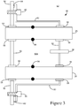
- FIG 3 is schematic diagram of an enclosure 48 for joints 54 of the refrigerant lines 26, 28 ( Figure 2 ), according to an embodiment.
- the joints 54 can include joints that are brazed, soldered, or mechanically secured to connect the refrigerant lines 26, 28 to the air handling unit 24.
- the enclosure 48 can, for example, in a situation in which one of the joints 54 develops a leak, contain the refrigerant leaking therefrom and vent the refrigerant (e.g., via vent aperture 70 in Figure 4 below) to the air handling unit 24 so that the leaking refrigerant can be mixed with air and diluted to a safe level.
- the air handling unit 24 may vent the diluted mixture including air and refrigerant to a space within the building.
- the enclosure 48 includes a housing 50.
- An interior space 50A is formed in the housing 50.
- the refrigerant lines 26 and 28 extend through the enclosure 48 such that the joints 54 are disposed inside the interior space 50A of the housing 50.
- the space outside the housing is identified as the space 52 for purposes of description.
- a refrigerant sensor 56 is secured to the housing 50.
- the refrigerant sensor 56 can detect a refrigerant leak in the interior space 50A.
- a plurality of gaskets 58 can be included to seal a connection location between the refrigerant lines 26, 28 and the housing 50.
- the housing could be secured to the refrigerant lines 26, 28 by, for example, a brazed or welded connection, in which case the gaskets 58 may not be included.
- a plurality of fasteners 60 such as, but not limited to, bolts, screws, rivets, combinations thereof, or the like, secure the enclosure 50 to the air handling unit 24.
- a gasket 60 can be disposed in the connection to provide additional sealing.
- An alarm 64 can be disposed between the pieces of the enclosure 48 such that if the air handling unit 24 is turned on without the enclosure 48 secured, an alarm signal is generated.
- the alarm signal can be an audible signal, an electronic signal that prevents operation of the HVACR system 20, combinations thereof, or the like.
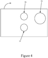
- Figure 4 is a schematic diagram of the enclosure 48, according to an embodiment.
- Figure 4 illustrates a vent aperture 70, and refrigerant line apertures 72, 74 disposed in the enclosure 48.
- the vent aperture 70 is fluidly connected to the air handling unit 24 so that if a refrigerant at joints 54 ( Figure 3 ) inside of the enclosure 48 leaks from the refrigerant lines 26, 28, the refrigerant can be vented via the air handling unit 24.
- the blower 30 may be enabled to provide an airflow for diluting the leaked refrigerant.
- the refrigerant line apertures 72, 74 are sized to accommodate refrigerant lines 26, 28 therethrough.
- a gasket or seal may be included between the refrigerant lines 26, 28 and the refrigerant line apertures 72, 74 so that an area inside the enclosure 48 is fluidly sealed from an area outside the enclosure 48.
- an area of the vent aperture 70 is generally larger than an area of each of the refrigerant line apertures 72, 74.
- the vent aperture 70 may be at or about 1.5 to at or about 4 times greater in area than the area of one of the refrigerant line apertures 72, 74.
- the vent aperture 70 may be at or about 2 times greater in area than the area of one of the refrigerant line apertures 72, 74. It is to be appreciated that Figure 4 is not drawn to scale.
- Figures 5A and 5B are schematic diagrams of a refrigerant sensor 100 within the interior space 22, according to an embodiment.
- Figure 5A illustrates a vent 102 in a wall 22A of the interior space 22 including the indoor system 20A ( Figure 2 ).
- the refrigerant sensor 100 may be included in a location of the vent 102.
- the refrigerant sensor 100 can be disposed in a location near a bottom of the vent 102.
- the refrigerant sensor 100 can be placed in a different location of the vent 102.
- the vent 102 can include a plurality of refrigerant sensors 100.
- the refrigerant sensor 100 may be, for example, an oxygen depletion sensor that indicates when a refrigerant leak has occurred from depletion in an amount of oxygen in the interior space 22.
- the refrigerant sensor 100 can be electronically connected to, for example, a controller of the HVACR system 20. In such an embodiment, if the refrigerant sensor 100 detects a refrigerant leak, the HVACR system 20 can generate an alarm signal; enable the blower 30; enable another fan in the interior space 22; combinations thereof; or the like.
- the vent 102 may already be present in the interior space 22. In an embodiment, the vent 102 may be added to the interior space 22. In an embodiment, a plurality of vents 102 may be present in the interior space 22, and one or more can be configured to include the refrigerant sensor 100.
- FIG 5B illustrates a vent 106 in a door 104 of the interior space 22 including the indoor system 20A ( Figure 2 ). Similar to the placement of the refrigerant sensor 100 in the vent 102 in the wall 22A in Figure 5A , the refrigerant sensor 100 can be placed in a location near a bottom of the vent 106 within the door 104. In an embodiment, the refrigerant sensor 100 can be placed in a different location of the vent 106. In an embodiment, a plurality of refrigerant sensors 100 can be included in the vent 106. It will be appreciated that the vent 106 may be present in the door 104, according to an embodiment, while in another embodiment, the vent 106 may be newly formed in the door 104.
- a refrigerant sensor 108 can be placed on a bottom edge of the door 104.
- the refrigerant sensor 108 can be placed on the bottom edge of the door 104 and the refrigerant sensor 100 can be placed in the vent 106.
- the refrigerant sensor 100 can be placed in the vent 106 and another refrigerant sensor 100 can be placed in the vent 102 ( Figure 5A ).
- the refrigerant sensor 108 can be the same as or similar to the refrigerant sensor 100.
- the refrigerant sensor 108 may be an oxygen depletion sensor that indicates when a refrigerant leak has occurred from depletion in an amount of oxygen in the interior space 22.
- the refrigerant sensor 108 can be electronically connected to, for example, a controller of the HVACR system 20. In such an embodiment, if the refrigerant sensor 100 detects a refrigerant leak, the HVACR system 20 can generate an alarm signal; enable the blower 30; enable another fan in the interior space 22; combinations thereof; or the like.
- Any one of aspects 1-5 can be combined with any one of aspects 6 - 11 or 12 - 18. Any one of aspects 6 - 11 can be combined with any one of aspects 12 - 18.
Landscapes
- Engineering & Computer Science (AREA)
- Mechanical Engineering (AREA)
- General Engineering & Computer Science (AREA)
- Chemical & Material Sciences (AREA)
- Combustion & Propulsion (AREA)
- Human Computer Interaction (AREA)
- Physics & Mathematics (AREA)
- Thermal Sciences (AREA)
- Air Conditioning Control Device (AREA)
Abstract
Description
- This disclosure relates generally to a heating, ventilation, air conditioning, and refrigeration (HVACR) system. More specifically, the disclosure relates to retrofitting equipment in an HVACR system to utilize a more environmentally friendly refrigerant.
- HVACR systems generally include a compressor, condenser, expansion device, and evaporator fluidly connected to form a refrigerant circuit. A refrigerant is provided for the refrigerant circuit. The refrigerant can be, for example, R-410A or similar refrigerants that are non-flammable.
- This disclosure relates generally to a heating, ventilation, air conditioning, and refrigeration (HVACR) system. More specifically, the disclosure relates to retrofitting equipment in an HVACR system to utilize a more environmentally friendly refrigerant.
- In an embodiment, an HVACR system can utilize R-410A as its refrigerant. In an embodiment, the R-410A refrigerant can be replaced with an alternative refrigerant. In an embodiment, the alternative refrigerant can be an environmentally friendly refrigerant having a lower global warming potential (GWP) than R-410A. In an embodiment, the HVACR system can utilize another refrigerant such as, but not limited to, R-22, R-404A, R-134A, or the like.
- A suitable alternative refrigerant includes, but is not limited to, DR-55. In an embodiment, DR55 may alternatively be referred to as R-452B. In an embodiment, the alternative refrigerant can alternatively be, for example, R-32, R-454B, or the like
- In an embodiment, the HVACR system includes at least a portion of equipment that is disposed within an occupied (or potentially occupied) space within the building. In an embodiment, the HVACR system includes equipment having brazed, soldered, or other mechanical connections in the occupied space that are external to the HVACR equipment. In an embodiment, to retrofit the HVACR system with environmentally refrigerant, sealed enclosures may be installed over the brazed, soldered, or other mechanical connections. In an embodiment, the sealed enclosures may include a vent. In an embodiment, the HVACR system can be retrofit to include one or more alarms or other failsafe features that will prevent operation of the HVACR system without appropriately installed enclosures and/or to provide an indication of a refrigerant leak.
- In an embodiment, a method of retrofitting includes removing an existing refrigerant and replacing or modifying an expansion device in the system.
- In an embodiment, the existing refrigerant that is removed can be reclaimed, recycled, and/or reformulated into lower GWP refrigerants.
- A method of retrofitting a heating, ventilation, air conditioning, and refrigeration system (HVACR) including one or more brazed, soldered, or mechanical connections between refrigerant lines is disclosed. The method includes removing a refrigerant from the HVACR system. The refrigerant that is removed is a non-flammable refrigerant. An enclosure is installed over the one or more brazed, soldered, or mechanical connections between refrigerant lines. A refrigerant is added to the HVACR system. The refrigerant being added has a global warming potential (GWP) that is relatively lower than the refrigerant removed from the HVACR system. The refrigerant being added has a relatively higher flammability than the refrigerant removed from the HVACR system.
- A heating, ventilation, air conditioning, and refrigeration (HVACR) system is disclosed. The HVACR system includes an indoor system. The indoor system includes one or more refrigerant lines; a brazed, soldered, or mechanical connection; and an enclosure. The enclosure includes a housing that encloses the brazed, soldered, or mechanical connection. A refrigerant circuit for the HVACR system includes a refrigerant that is a flammable refrigerant.
- A system is disclosed. The system includes an interior space and an HVACR system. The HVACR system includes an indoor system and an outdoor system. The indoor system is disposed within the interior space. The indoor system includes one or more refrigerant lines and a brazed, soldered, or mechanical connection, an enclosure including a housing that encloses the brazed, soldered, or mechanical connection, and a refrigerant circuit. A refrigerant in the refrigerant circuit includes a flammable refrigerant.
- References are made to the accompanying drawings that form a part of this disclosure and which illustrate embodiments in which the systems and methods described in this specification can be practiced.
-
Figure 1 is a schematic diagram of a refrigeration circuit, according to an embodiment. -
Figure 2 is a schematic diagram of a heating, ventilation, air conditioning, and refrigeration (HVACR) system, according to an embodiment. -
Figure 3 is a schematic diagram of a sealed enclosure, according to an embodiment. -
Figure 4 is a schematic diagram of the sealed enclosure, according to an embodiment. -
Figures 5A and5B are schematic diagrams of a refrigerant sensor, according to an embodiment. - Like reference numbers represent like parts throughout.
- This disclosure relates generally to a heating, ventilation, air conditioning, and refrigeration (HVACR) system. More specifically, the disclosure relates to retrofitting equipment in an HVACR system to utilize a more environmentally friendly refrigerant.
- Approximately 60 - 80% of the market share for HVACR systems involves retrofitting existing equipment, for example, to utilize a more environmentally friendly refrigerant. More environmentally friendly refrigerants may have an increased flammability relative to the existing refrigerant. Retrofitting an HVACR system to utilize a more environmentally friendly refrigerant that is flammable may offer a lower cost option to the HVACR equipment owner than replacing the HVACR system entirely. However, because the replacement refrigerants are flammable, modifications may be needed to the HVACR system to safely utilize the flammable refrigerants.
- A refrigerant may be considered environmentally friendly when it has a 100 year direct global warming potential (GWP) of less than 148 times that of carbon dioxide. GWP is a relative measure of how much heat a greenhouse gas traps in the atmosphere as compared to carbon dioxide as a reference. A GWP is calculated over a specific time interval, commonly 20, 100 or 480 years. GWP is expressed as a factor of carbon dioxide (whose GWP is standardized to 1). The higher GWP potential for a refrigerant results in greater potential to contribute to global climate change.
- Sometimes, when formulating refrigerants that are considered environmentally friendly, such as, but not limited to, DR-55, R-454B, or R-32, a flammability of the refrigerant may be increased. For example, DR-55 has a relatively lower GWP than R-410A. However, DR-55 has a relatively higher flammability than R-410A. Accordingly, when retrofitting an HVACR system that utilizes R-410A as a refrigerant with DR-55, additional modifications to equipment of the HVACR system may be made to account for the increased flammability.
-
Figure 1 is a schematic diagram of arefrigerant circuit 10, according to an embodiment. Therefrigerant circuit 10 generally includes acompressor 12, acondenser 14, an expansion device 16 (e.g., expansion valve), and anevaporator 18. Therefrigerant circuit 10 is an example and can be modified to include additional components. For example, in an embodiment, therefrigerant circuit 10 can include other components such as, but not limited to, an economizer heat exchanger, one or more flow control devices, a receiver tank, a dryer, a suction-liquid heat exchanger, or the like. - The
refrigerant circuit 10 can generally be applied in a variety of systems used to control an environmental condition (e.g., temperature, humidity, air quality, or the like) in a space (generally referred to as a conditioned space). Examples of such systems include, but are not limited to, HVACR systems, transport refrigeration systems, or the like. - The
compressor 12,condenser 14,expansion device 16, andevaporator 18 are fluidly connected viarefrigerant lines refrigerant lines refrigerant conduits - In an embodiment, the
refrigerant circuit 10 can be configured to be a cooling system (e.g., an air conditioning system) capable of operating in a cooling mode. In an embodiment, therefrigerant circuit 10 can be configured to be a heat pump system that can operate in both a cooling mode and a heating/defrost mode. - The
refrigerant circuit 10 can operate according to generally known principles. Therefrigerant circuit 10 can be configured to heat or cool a gaseous process fluid (e.g., a heat transfer medium or fluid such as, but not limited to, air or the like), in which case therefrigerant circuit 10 may be generally representative of an air conditioner or heat pump. - In operation, the
compressor 12 compresses a working fluid (e.g., a heat transfer fluid such as a refrigerant or the like) from a relatively lower pressure gas to a relatively higher-pressure gas. The relatively higher-pressure gas is also at a relatively higher temperature, which is discharged from thecompressor 12 and flows throughrefrigerant line 19 to thecondenser 14. The working fluid flows through thecondenser 10 and rejects heat to a process fluid (e.g., water, air, etc.), thereby cooling the working fluid. The cooled working fluid, which is now in a liquid form, flows to theexpansion device 16 via therefrigerant line 26. Theexpansion device 16 reduces the pressure of the working fluid. As a result, a portion of the working fluid is converted to a gaseous form. The working fluid, which is now in a mixed liquid and gaseous form flows to theevaporator 18 via the remainder ofrefrigerant line 26. The working fluid flows through theevaporator 18 and absorbs heat from a process fluid (e.g., water, air, etc.), heating the working fluid, and converting it to a gaseous form. The gaseous working fluid then returns to thecompressor 12 via therefrigerant line 28. The above-described process continues while the refrigerant circuit is operating, for example, in a cooling mode (e.g., while thecompressor 12 is enabled). -
Figure 2 is a schematic diagram of anHVACR system 20, according to an embodiment. TheHVACR system 20 includes anindoor system 20A and anoutdoor system 20B. Theindoor system 20A is disposed within aninterior space 22, while theoutdoor system 20B is located outside theinterior space 22. In an embodiment, theoutdoor system 20B may be located on an opposite side of a wall forming theinterior space 22. In an embodiment, theoutdoor system 20B can alternatively be located within theinterior space 22, such that theHVACR system 20 includes theindoor system 20A and theoutdoor system 20B. TheHVACR system 20 may be representative of a residential HVACR system, according to an embodiment. - The
indoor system 20A generally includesHVACR equipment 24. In the illustrated embodiment, theHVACR equipment 24 may be representative of an air handling unit. As such, theHVACR equipment 24 may be referred to as theair handling unit 24. Theair handling unit 24 includes ablower 30. Theblower 30 is configured to force air across anevaporator 18 of the refrigerant circuit (e.g.,refrigerant circuit 10 inFigure 1 ). Theevaporator 18 may be disposed within anair supply duct 32. The air blown across theevaporator 18 exchanges heat with the refrigerant in therefrigerant circuit 10 to control a temperature of the air being supplied to one or more conditioned spaces of theHVACR system 20. Theair supply duct 32 provides the temperature controlled air to the various conditioned spaces. It will be appreciated that theair supply duct 32 would be connected to a network of ducts in theHVACR system 20 to supply the temperature controlled air to the various conditioned spaces. Areturn air duct 34 receives air from the one or more conditioned spaces, and provides the air to theblower 30. Prior to being provided to theblower 30, the return air is filtered via afilter 36. - The
outdoor system 20B generally includes acompressor 12 and acondenser 14 disposed within ahousing 37. Thehousing 37 may sometimes be referred to as a cabinet or the like. Acondenser fan 38 can be included to draw air across thecondenser 14 so that refrigerant of therefrigerant circuit 10 exchanges heat with the air. - The
refrigerant circuit 10 includes features in theindoor system 20A and features in theoutdoor system 20B.Refrigerant lines HVACR system 20 is an air conditioning unit, one of therefrigerant lines outdoor system 20B to theindoor system 20A, and the other of therefrigerant lines indoor system 20A to theoutdoor system 20B. In an embodiment in which theHVACR system 20 is a heat pump unit, a direction of flow of the refrigerant throughrefrigerant lines refrigerant lines indoor system 20A that include brazed, soldered, or mechanical refrigerant joints 54 (described in further detail in accordance withFigure 3 below) that are external to theair handling unit 24. In an embodiment in which theHVACR system 20 is retrofitted with a refrigerant that is more environmentally friendly than, for example, R410A, the joints may be further sealed to prevent leaking of the replacement refrigerant, which may be flammable, into the space in which theindoor system 20A is disposed. In an embodiment, the existing refrigerant that is removed can be reclaimed, recycled, and/or reformulated into lower GWP refrigerants. -
Figure 3 is schematic diagram of anenclosure 48 forjoints 54 of therefrigerant lines 26, 28 (Figure 2 ), according to an embodiment. Thejoints 54 can include joints that are brazed, soldered, or mechanically secured to connect therefrigerant lines air handling unit 24. Theenclosure 48 can, for example, in a situation in which one of thejoints 54 develops a leak, contain the refrigerant leaking therefrom and vent the refrigerant (e.g., viavent aperture 70 inFigure 4 below) to theair handling unit 24 so that the leaking refrigerant can be mixed with air and diluted to a safe level. In an embodiment, theair handling unit 24 may vent the diluted mixture including air and refrigerant to a space within the building. - The
enclosure 48 includes ahousing 50. Aninterior space 50A is formed in thehousing 50. Therefrigerant lines enclosure 48 such that thejoints 54 are disposed inside theinterior space 50A of thehousing 50. The space outside the housing is identified as thespace 52 for purposes of description. Arefrigerant sensor 56 is secured to thehousing 50. Therefrigerant sensor 56 can detect a refrigerant leak in theinterior space 50A. A plurality ofgaskets 58 can be included to seal a connection location between therefrigerant lines housing 50. In an embodiment, the housing could be secured to therefrigerant lines gaskets 58 may not be included. A plurality offasteners 60 such as, but not limited to, bolts, screws, rivets, combinations thereof, or the like, secure theenclosure 50 to theair handling unit 24. In an embodiment, agasket 60 can be disposed in the connection to provide additional sealing. Analarm 64 can be disposed between the pieces of theenclosure 48 such that if theair handling unit 24 is turned on without theenclosure 48 secured, an alarm signal is generated. In an embodiment, the alarm signal can be an audible signal, an electronic signal that prevents operation of theHVACR system 20, combinations thereof, or the like. -
Figure 4 is a schematic diagram of theenclosure 48, according to an embodiment.Figure 4 illustrates avent aperture 70, and refrigerant line apertures 72, 74 disposed in theenclosure 48. Thevent aperture 70 is fluidly connected to theair handling unit 24 so that if a refrigerant at joints 54 (Figure 3 ) inside of theenclosure 48 leaks from therefrigerant lines air handling unit 24. Theblower 30 may be enabled to provide an airflow for diluting the leaked refrigerant. The refrigerant line apertures 72, 74 are sized to accommodaterefrigerant lines Figure 3 above, a gasket or seal may be included between therefrigerant lines enclosure 48 is fluidly sealed from an area outside theenclosure 48. - In an embodiment, an area of the
vent aperture 70 is generally larger than an area of each of the refrigerant line apertures 72, 74. For example, in an embodiment, thevent aperture 70 may be at or about 1.5 to at or about 4 times greater in area than the area of one of the refrigerant line apertures 72, 74. In an embodiment, thevent aperture 70 may be at or about 2 times greater in area than the area of one of the refrigerant line apertures 72, 74. It is to be appreciated thatFigure 4 is not drawn to scale. -
Figures 5A and5B are schematic diagrams of arefrigerant sensor 100 within theinterior space 22, according to an embodiment.Figure 5A illustrates avent 102 in awall 22A of theinterior space 22 including theindoor system 20A (Figure 2 ). Therefrigerant sensor 100 may be included in a location of thevent 102. In an embodiment, therefrigerant sensor 100 can be disposed in a location near a bottom of thevent 102. In an embodiment, therefrigerant sensor 100 can be placed in a different location of thevent 102. In an embodiment, thevent 102 can include a plurality ofrefrigerant sensors 100. Therefrigerant sensor 100 may be, for example, an oxygen depletion sensor that indicates when a refrigerant leak has occurred from depletion in an amount of oxygen in theinterior space 22. In an embodiment, therefrigerant sensor 100 can be electronically connected to, for example, a controller of theHVACR system 20. In such an embodiment, if therefrigerant sensor 100 detects a refrigerant leak, theHVACR system 20 can generate an alarm signal; enable theblower 30; enable another fan in theinterior space 22; combinations thereof; or the like. In an embodiment, thevent 102 may already be present in theinterior space 22. In an embodiment, thevent 102 may be added to theinterior space 22. In an embodiment, a plurality ofvents 102 may be present in theinterior space 22, and one or more can be configured to include therefrigerant sensor 100. -
Figure 5B illustrates avent 106 in adoor 104 of theinterior space 22 including theindoor system 20A (Figure 2 ). Similar to the placement of therefrigerant sensor 100 in thevent 102 in thewall 22A inFigure 5A , therefrigerant sensor 100 can be placed in a location near a bottom of thevent 106 within thedoor 104. In an embodiment, therefrigerant sensor 100 can be placed in a different location of thevent 106. In an embodiment, a plurality ofrefrigerant sensors 100 can be included in thevent 106. It will be appreciated that thevent 106 may be present in thedoor 104, according to an embodiment, while in another embodiment, thevent 106 may be newly formed in thedoor 104. In another embodiment, arefrigerant sensor 108 can be placed on a bottom edge of thedoor 104. In an embodiment, therefrigerant sensor 108 can be placed on the bottom edge of thedoor 104 and therefrigerant sensor 100 can be placed in thevent 106. It will be appreciated that in an embodiment, therefrigerant sensor 100 can be placed in thevent 106 and anotherrefrigerant sensor 100 can be placed in the vent 102 (Figure 5A ). - The
refrigerant sensor 108 can be the same as or similar to therefrigerant sensor 100. For example, therefrigerant sensor 108 may be an oxygen depletion sensor that indicates when a refrigerant leak has occurred from depletion in an amount of oxygen in theinterior space 22. In an embodiment, therefrigerant sensor 108 can be electronically connected to, for example, a controller of theHVACR system 20. In such an embodiment, if therefrigerant sensor 100 detects a refrigerant leak, theHVACR system 20 can generate an alarm signal; enable theblower 30; enable another fan in theinterior space 22; combinations thereof; or the like. - Any one of aspects 1-5 can be combined with any one of aspects 6 - 11 or 12 - 18. Any one of aspects 6 - 11 can be combined with any one of aspects 12 - 18.
- Aspect 1. A method of retrofitting a heating, ventilation, air conditioning, and refrigeration system (HVACR) including one or more brazed, soldered, or mechanical connections between refrigerant lines, the method comprising:
- removing a refrigerant from the HVACR system, the refrigerant being a non-flammable refrigerant;
- installing an enclosure over the one or more brazed, soldered, or mechanical connections between refrigerant lines;
- adding refrigerant to the HVACR system, the refrigerant being added having a global warming potential (GWP) that is relatively lower than the refrigerant removed from the HVACR system, and the refrigerant being added having a relatively higher flammability than the refrigerant removed from the HVACR system.
- Aspect 2. The method according to aspect 1, further comprising:
- adding ventilation to the room by one of installing one or more vents to a wall of a space in which the HVACR system is disposed or installing one or more vents to a door of the space in which the HVACR system is disposed.
- Aspect 3. The method according to any one of aspects 1 or 2, further comprising:
installing one or more refrigerant sensors in a space in which the HVACR system is disposed. - Aspect 4. The method according to any one of aspects 1 - 3, further comprising:
replacing an expansion device. - Aspect 5. The method according to any one of aspects 1 - 4, further comprising:
capturing the removed refrigerant for repurposing. - Aspect 6. A heating, ventilation, air conditioning, and refrigeration (HVACR) system, comprising:
- an indoor system, the indoor system including:
- one or more refrigerant lines;
- a brazed, soldered, or mechanical connection; and
- an enclosure, the enclosure including a housing that encloses the brazed, soldered, or mechanical connection, and
- a refrigerant circuit, wherein a refrigerant in the refrigerant circuit includes a flammable refrigerant.
- an indoor system, the indoor system including:
- Aspect 7. The HVACR system according to aspect 6, further comprising an outdoor system, the outdoor system including a compressor, condenser, and a condenser fan.
- Aspect 8. The HVACR system according to any one of aspects 6 or 7, wherein the indoor system is disposed in an occupied space of a building.
- Aspect 9. The HVACR system according to aspect 8, wherein the occupied space includes one or more vents disposed in one of a wall and a door of the occupied space.
-
Aspect 10. The HVACR system according to aspect 8, wherein the enclosure includes an alarm that generates an alarm signal in response to detection of a refrigerant leak. - Aspect 11. The HVACR system according to
aspect 10, wherein the enclosure includes a refrigerant sensor that is electronically connected to the alarm for indicating when a refrigerant leak is detected. -
Aspect 12. A system, comprising:- an interior space; and
- an HVACR system, the HVACR system including an indoor system and an outdoor system, the indoor system being disposed within the interior space, wherein the indoor system includes one or more refrigerant lines and a brazed, soldered, or mechanical connection, an enclosure including a housing that encloses the brazed, soldered, or mechanical connection, and a refrigerant circuit, wherein a refrigerant in the refrigerant circuit includes a flammable refrigerant.
- Aspect 13. The system according to
aspect 12, wherein the HVACR system includes an outdoor system disposed outside of the interior space, the outdoor system including a compressor, condenser, and a condenser fan. -
Aspect 14. The system according to any one ofaspects 12 or 13, wherein the interior space includes one or more vents disposed in one of a wall and a door of the interior space. - Aspect 15. The system according to
aspect 14, wherein the interior space includes one or more refrigerant sensors disposed in at least one of the one or more vents. -
Aspect 16. The system according to aspect 15, wherein the one or more refrigerant sensors are oxygen depletion sensors. - Aspect 17. The system according to any one of aspects 12 - 16, wherein the enclosure includes an alarm that generates an alarm signal in response to detection of a refrigerant leak within the housing of the enclosure.
-
Aspect 18. The system according to aspect 17, wherein the enclosure includes a refrigerant sensor that is electronically connected to the alarm for indicating when a refrigerant leak is detected. - The terminology used in this specification is intended to describe particular embodiments and is not intended to be limiting. The terms "a," "an," and "the" include plural forms as well, unless clearly indicated otherwise. The terms "comprises" and/or "comprising," when used, indicated the presence of the stated features, integers, steps, operations, elements, and/or components, but do not preclude the presence or addition of one or more other features, integers, steps, operations, elements, and/or components.
- With regard to the preceding description, it is to be understood that changes may be made in detail, especially in matters of the construction materials employed and the shape, size, and arrangement of parts, without departing from the scope of the present disclosure. The word "embodiment" may, but does not necessarily, refer to the same embodiment. The embodiments and disclosure are examples only. Other and further embodiments may be devised without departing from the basic scope thereof, with the true scope and spirit of the disclosure being indicated by the claims that follow.
Claims (15)
- A method of retrofitting a heating, ventilation, air conditioning, and refrigeration system (HVACR) including one or more brazed, soldered, or mechanical connections between refrigerant lines, the method comprising:removing a refrigerant from the HVACR system, the refrigerant being a non-flammable refrigerant;installing an enclosure over the one or more brazed, soldered, or mechanical connections between refrigerant lines;adding refrigerant to the HVACR system, the refrigerant being added having a global warming potential (GWP) that is relatively lower than the refrigerant removed from the HVACR system, and the refrigerant being added having a relatively higher flammability than the refrigerant removed from the HVACR system.
- The method according to claim 1, further comprising:adding ventilation to the room by one of installing one or more vents to a wall of a space in which the HVACR system is disposed or installing one or more vents to a door of the space in which the HVACR system is disposed.
- The method according to claim 1 or 2, further comprising:installing one or more refrigerant sensors in a space in which the HVACR system is disposed.
- The method according to any of the preceding claims, further comprising:replacing an expansion device.
- The method according to any of the preceding claims, further comprising:capturing the removed refrigerant for repurposing.
- A heating, ventilation, air conditioning, and refrigeration (HVACR) system, comprising:an indoor system, the indoor system including:one or more refrigerant lines;a brazed, soldered, or mechanical connection; andan enclosure, the enclosure including a housing that encloses the brazed, soldered, or mechanical connection, anda refrigerant circuit, wherein a refrigerant in the refrigerant circuit includes a flammable refrigerant.
- The HVACR system according to claim 6, further comprising an outdoor system, the outdoor system including a compressor, condenser, and a condenser fan.
- The HVACR system according to claim 6 or 7, wherein the indoor system is disposed in an occupied space of a building.
- The HVACR system according to claim 8, wherein the occupied space includes one or more vents disposed in one of a wall and a door of the occupied space.
- The HVACR system according to claim 8 or 9, wherein the enclosure includes an alarm that generates an alarm signal in response to detection of a refrigerant leak.
- The HVACR system according to claim 10, wherein the enclosure includes a refrigerant sensor that is electronically connected to the alarm for indicating when a refrigerant leak is detected.
- The HVACR system according to any of claims 6 - 11, wherein the indoor system is disposed within an interior space.
- The HVACR system according to claim 12, wherein the HVACR system includes an outdoor system disposed outside of the interior space, the outdoor system including a compressor, condenser, and a condenser fan.
- The HVACR system according to claim 12 or 13, wherein the interior space includes one or more vents disposed in one of a wall and a door of the interior space.
- The HVACR system according to claim 14, wherein the interior space includes one or more refrigerant sensors disposed in at least one of the one or more vents, the one or more refrigerant sensors being oxygen depletion sensors.
Priority Applications (1)
| Application Number | Priority Date | Filing Date | Title |
|---|---|---|---|
| EP23152798.7A EP4187167A1 (en) | 2017-12-26 | 2018-12-17 | Hvac product for flammable refrigerant |
Applications Claiming Priority (1)
| Application Number | Priority Date | Filing Date | Title |
|---|---|---|---|
| US201762610464P | 2017-12-26 | 2017-12-26 |
Related Child Applications (1)
| Application Number | Title | Priority Date | Filing Date |
|---|---|---|---|
| EP23152798.7A Division EP4187167A1 (en) | 2017-12-26 | 2018-12-17 | Hvac product for flammable refrigerant |
Publications (2)
| Publication Number | Publication Date |
|---|---|
| EP3505842A1 true EP3505842A1 (en) | 2019-07-03 |
| EP3505842B1 EP3505842B1 (en) | 2023-01-25 |
Family
ID=64744526
Family Applications (2)
| Application Number | Title | Priority Date | Filing Date |
|---|---|---|---|
| EP23152798.7A Pending EP4187167A1 (en) | 2017-12-26 | 2018-12-17 | Hvac product for flammable refrigerant |
| EP18213237.3A Active EP3505842B1 (en) | 2017-12-26 | 2018-12-17 | Retrofitting r-410a hvac products to handle flammable refrigerants |
Family Applications Before (1)
| Application Number | Title | Priority Date | Filing Date |
|---|---|---|---|
| EP23152798.7A Pending EP4187167A1 (en) | 2017-12-26 | 2018-12-17 | Hvac product for flammable refrigerant |
Country Status (3)
| Country | Link |
|---|---|
| US (2) | US11162722B2 (en) |
| EP (2) | EP4187167A1 (en) |
| CN (1) | CN210107793U (en) |
Cited By (4)
| Publication number | Priority date | Publication date | Assignee | Title |
|---|---|---|---|---|
| WO2021176625A1 (en) | 2020-03-04 | 2021-09-10 | ダイキン工業株式会社 | Refrigerant cycle apparatus and method for installing refrigerant cycle apparatus |
| EP4119942A1 (en) * | 2021-07-14 | 2023-01-18 | Carrier Corporation | Methods of reducing the occurence of false positives in gas detectors |
| WO2023232503A1 (en) * | 2022-05-30 | 2023-12-07 | Bdr Thermea Group B.V. | Enclosure for a heat pump |
| EP4361513A1 (en) * | 2022-10-27 | 2024-05-01 | BDR Thermea Group B.V. | Enclosure for a heat pump |
Families Citing this family (11)
| Publication number | Priority date | Publication date | Assignee | Title |
|---|---|---|---|---|
| EP3712533B1 (en) * | 2017-11-16 | 2023-09-20 | Hitachi-Johnson Controls Air Conditioning, Inc. | Air conditioner |
| EP4187167A1 (en) * | 2017-12-26 | 2023-05-31 | Trane International Inc. | Hvac product for flammable refrigerant |
| SG11202012779PA (en) * | 2019-05-17 | 2021-12-30 | Carrier Corp | Gas detector test and calibration method and apparatus |
| US11231198B2 (en) | 2019-09-05 | 2022-01-25 | Trane International Inc. | Systems and methods for refrigerant leak detection in a climate control system |
| US11125457B1 (en) * | 2020-07-16 | 2021-09-21 | Emerson Climate Technologies, Inc. | Refrigerant leak sensor and mitigation device and methods |
| JP7260806B2 (en) * | 2021-04-27 | 2023-04-19 | ダイキン工業株式会社 | Air conditioning system, operation control method thereof, and operation control device for air conditioning system |
| US12487008B2 (en) | 2022-01-14 | 2025-12-02 | Trane International Inc. | Method of commissioning an HVAC system |
| US12117191B2 (en) | 2022-06-24 | 2024-10-15 | Trane International Inc. | Climate control system with improved leak detector |
| US12504190B2 (en) | 2023-10-17 | 2025-12-23 | Trane International Inc. | Air conditioning unit with a leak ventilation inducer |
| US12516839B2 (en) | 2023-10-17 | 2026-01-06 | Trane International Inc. | Ventilation air valve, and air conditioning unit thereof |
| WO2026055411A2 (en) * | 2024-09-06 | 2026-03-12 | The Chemours Company Fc, Llc | Thermal management fluid conversion composition |
Citations (3)
| Publication number | Priority date | Publication date | Assignee | Title |
|---|---|---|---|---|
| JP2002174448A (en) * | 2000-12-08 | 2002-06-21 | Denso Corp | Air conditioner |
| WO2013038599A1 (en) * | 2011-09-14 | 2013-03-21 | パナソニック株式会社 | Air conditioner |
| EP3040654A1 (en) * | 2013-08-26 | 2016-07-06 | Mitsubishi Electric Corporation | Air conditioning device and refrigerant leak detection method |
Family Cites Families (14)
| Publication number | Priority date | Publication date | Assignee | Title |
|---|---|---|---|---|
| US2967429A (en) * | 1960-01-29 | 1961-01-10 | Honeywell Regulator Co | Measuring apparatus |
| US5918475A (en) * | 1995-10-11 | 1999-07-06 | Denso Corporation | Air conditioning apparatus for vehicle, using a flammable refrigerant |
| JP3159200B2 (en) * | 1999-03-02 | 2001-04-23 | ダイキン工業株式会社 | Air conditioner |
| DE10029186C2 (en) * | 2000-06-19 | 2002-04-25 | Heraeus Electro Nite Int | Temperature-measuring device |
| JP3985556B2 (en) * | 2002-03-18 | 2007-10-03 | ダイキン工業株式会社 | Electrical insulation device for air conditioner and air conditioner having the same |
| JP4466448B2 (en) * | 2005-04-18 | 2010-05-26 | 株式会社デンソー | Air conditioner for vehicles |
| JP3885817B2 (en) * | 2005-04-19 | 2007-02-28 | ダイキン工業株式会社 | Branch refrigerant relay unit and manufacturing method thereof |
| WO2007145624A1 (en) * | 2006-06-13 | 2007-12-21 | Carrier Corporation | Insulation temperature sensor |
| US20100154453A1 (en) * | 2008-12-18 | 2010-06-24 | Winkler Kelly P | Line set box for protecting refrigerant lines and method of use thereof |
| JP6050671B2 (en) * | 2012-12-07 | 2016-12-21 | ダイキン工業株式会社 | Method of manufacturing piping unit of air conditioner and method of installing air conditioner |
| JP5665937B1 (en) * | 2013-09-13 | 2015-02-04 | 三菱電機株式会社 | Refrigeration cycle equipment |
| WO2017109824A1 (en) * | 2015-12-21 | 2017-06-29 | 三菱電機株式会社 | Refrigeration cycle device |
| EP4187167A1 (en) * | 2017-12-26 | 2023-05-31 | Trane International Inc. | Hvac product for flammable refrigerant |
| US11397017B2 (en) * | 2019-09-24 | 2022-07-26 | Lennox Industries Inc. | System and method for sealing and supporting external pipe connections in fluid lines and directing escaped fluids to a cabinet in an HVAC system |
-
2018
- 2018-12-17 EP EP23152798.7A patent/EP4187167A1/en active Pending
- 2018-12-17 EP EP18213237.3A patent/EP3505842B1/en active Active
- 2018-12-20 US US16/227,379 patent/US11162722B2/en active Active
- 2018-12-25 CN CN201822180314.0U patent/CN210107793U/en active Active
-
2021
- 2021-11-01 US US17/453,127 patent/US11703240B2/en active Active
Patent Citations (3)
| Publication number | Priority date | Publication date | Assignee | Title |
|---|---|---|---|---|
| JP2002174448A (en) * | 2000-12-08 | 2002-06-21 | Denso Corp | Air conditioner |
| WO2013038599A1 (en) * | 2011-09-14 | 2013-03-21 | パナソニック株式会社 | Air conditioner |
| EP3040654A1 (en) * | 2013-08-26 | 2016-07-06 | Mitsubishi Electric Corporation | Air conditioning device and refrigerant leak detection method |
Non-Patent Citations (1)
| Title |
|---|
| PAUL EVANS: "Refrigerant retrofit guide - The Engineering Mindset", 22 September 2017 (2017-09-22), XP055575833, Retrieved from the Internet <URL:https://theengineeringmindset.com/refrigerant-retrofit-guide/> [retrieved on 20190329] * |
Cited By (7)
| Publication number | Priority date | Publication date | Assignee | Title |
|---|---|---|---|---|
| WO2021176625A1 (en) | 2020-03-04 | 2021-09-10 | ダイキン工業株式会社 | Refrigerant cycle apparatus and method for installing refrigerant cycle apparatus |
| JPWO2021176625A1 (en) * | 2020-03-04 | 2021-09-10 | ||
| US12345454B2 (en) | 2020-03-04 | 2025-07-01 | Daikin Industries, Ltd. | Refrigerant cycle apparatus and method for installing refrigerant cycle apparatus |
| EP4119942A1 (en) * | 2021-07-14 | 2023-01-18 | Carrier Corporation | Methods of reducing the occurence of false positives in gas detectors |
| US12282008B2 (en) | 2021-07-14 | 2025-04-22 | Carrier Corporation | Methods of reducing the occurance of false positives in gas detectors |
| WO2023232503A1 (en) * | 2022-05-30 | 2023-12-07 | Bdr Thermea Group B.V. | Enclosure for a heat pump |
| EP4361513A1 (en) * | 2022-10-27 | 2024-05-01 | BDR Thermea Group B.V. | Enclosure for a heat pump |
Also Published As
| Publication number | Publication date |
|---|---|
| US20220049884A1 (en) | 2022-02-17 |
| US20190195542A1 (en) | 2019-06-27 |
| US11703240B2 (en) | 2023-07-18 |
| EP4187167A1 (en) | 2023-05-31 |
| EP3505842B1 (en) | 2023-01-25 |
| US11162722B2 (en) | 2021-11-02 |
| CN210107793U (en) | 2020-02-21 |
Similar Documents
| Publication | Publication Date | Title |
|---|---|---|
| US11703240B2 (en) | Retrofitting R410A HVAC products to handle flammable refrigerants | |
| CN104456721B (en) | Refrigeration cycle device | |
| US20210131706A1 (en) | Air conditioner and indoor unit | |
| CN113412401B (en) | Refrigerant circulation device | |
| US10655884B2 (en) | Air conditioner | |
| EP3321607B1 (en) | Refrigeration cycle device and refrigeration cycle system | |
| JP5931688B2 (en) | Air conditioner | |
| JP6079061B2 (en) | Refrigeration equipment | |
| AU2020290866A1 (en) | Refrigerant cycle apparatus | |
| JPWO2020059006A1 (en) | Refrigeration cycle equipment | |
| JP2017053517A (en) | Air conditioning system | |
| US20180306453A1 (en) | Air-Conditioning Device, in particular for a Rail Vehicle | |
| WO2023157568A1 (en) | Air conditioning system | |
| WO2017002214A1 (en) | Refrigeration cycle system | |
| US20040011072A1 (en) | Air conditioner and method of installing the air conditioner | |
| US11692725B2 (en) | Air-conditioning system with refrigerant leak detection and countermeasures | |
| US20220373205A1 (en) | Air-conditioning system | |
| EP4279824A1 (en) | Air conditioner | |
| US20250020339A1 (en) | Outdoor unit of air conditioner and air conditioner including the same | |
| EP4641099A1 (en) | Outdoor unit of air conditioner, and air conditioner having same | |
| US20250020341A1 (en) | Outdoor unit of air conditioner and air conditioner including the same | |
| JP2021162232A (en) | Air conditioner | |
| US12345454B2 (en) | Refrigerant cycle apparatus and method for installing refrigerant cycle apparatus | |
| CN219913249U (en) | Air duct machine | |
| US20250020343A1 (en) | Outdoor unit of air conditioner |
Legal Events
| Date | Code | Title | Description |
|---|---|---|---|
| PUAI | Public reference made under article 153(3) epc to a published international application that has entered the european phase |
Free format text: ORIGINAL CODE: 0009012 |
|
| STAA | Information on the status of an ep patent application or granted ep patent |
Free format text: STATUS: THE APPLICATION HAS BEEN PUBLISHED |
|
| AK | Designated contracting states |
Kind code of ref document: A1 Designated state(s): AL AT BE BG CH CY CZ DE DK EE ES FI FR GB GR HR HU IE IS IT LI LT LU LV MC MK MT NL NO PL PT RO RS SE SI SK SM TR |
|
| AX | Request for extension of the european patent |
Extension state: BA ME |
|
| STAA | Information on the status of an ep patent application or granted ep patent |
Free format text: STATUS: REQUEST FOR EXAMINATION WAS MADE |
|
| 17P | Request for examination filed |
Effective date: 20200103 |
|
| RBV | Designated contracting states (corrected) |
Designated state(s): AL AT BE BG CH CY CZ DE DK EE ES FI FR GB GR HR HU IE IS IT LI LT LU LV MC MK MT NL NO PL PT RO RS SE SI SK SM TR |
|
| STAA | Information on the status of an ep patent application or granted ep patent |
Free format text: STATUS: EXAMINATION IS IN PROGRESS |
|
| 17Q | First examination report despatched |
Effective date: 20201130 |
|
| GRAP | Despatch of communication of intention to grant a patent |
Free format text: ORIGINAL CODE: EPIDOSNIGR1 |
|
| STAA | Information on the status of an ep patent application or granted ep patent |
Free format text: STATUS: GRANT OF PATENT IS INTENDED |
|
| INTG | Intention to grant announced |
Effective date: 20220310 |
|
| GRAJ | Information related to disapproval of communication of intention to grant by the applicant or resumption of examination proceedings by the epo deleted |
Free format text: ORIGINAL CODE: EPIDOSDIGR1 |
|
| STAA | Information on the status of an ep patent application or granted ep patent |
Free format text: STATUS: EXAMINATION IS IN PROGRESS |
|
| GRAP | Despatch of communication of intention to grant a patent |
Free format text: ORIGINAL CODE: EPIDOSNIGR1 |
|
| STAA | Information on the status of an ep patent application or granted ep patent |
Free format text: STATUS: GRANT OF PATENT IS INTENDED |
|
| INTC | Intention to grant announced (deleted) | ||
| INTG | Intention to grant announced |
Effective date: 20220727 |
|
| GRAS | Grant fee paid |
Free format text: ORIGINAL CODE: EPIDOSNIGR3 |
|
| GRAA | (expected) grant |
Free format text: ORIGINAL CODE: 0009210 |
|
| STAA | Information on the status of an ep patent application or granted ep patent |
Free format text: STATUS: THE PATENT HAS BEEN GRANTED |
|
| AK | Designated contracting states |
Kind code of ref document: B1 Designated state(s): AL AT BE BG CH CY CZ DE DK EE ES FI FR GB GR HR HU IE IS IT LI LT LU LV MC MK MT NL NO PL PT RO RS SE SI SK SM TR |
|
| REG | Reference to a national code |
Ref country code: GB Ref legal event code: FG4D |
|
| REG | Reference to a national code |
Ref country code: CH Ref legal event code: EP |
|
| REG | Reference to a national code |
Ref country code: AT Ref legal event code: REF Ref document number: 1546158 Country of ref document: AT Kind code of ref document: T Effective date: 20230215 Ref country code: IE Ref legal event code: FG4D |
|
| REG | Reference to a national code |
Ref country code: DE Ref legal event code: R096 Ref document number: 602018045692 Country of ref document: DE |
|
| REG | Reference to a national code |
Ref country code: LT Ref legal event code: MG9D |
|
| REG | Reference to a national code |
Ref country code: NL Ref legal event code: MP Effective date: 20230125 |
|
| P01 | Opt-out of the competence of the unified patent court (upc) registered |
Effective date: 20230505 |
|
| REG | Reference to a national code |
Ref country code: AT Ref legal event code: MK05 Ref document number: 1546158 Country of ref document: AT Kind code of ref document: T Effective date: 20230125 |
|
| PG25 | Lapsed in a contracting state [announced via postgrant information from national office to epo] |
Ref country code: NL Free format text: LAPSE BECAUSE OF FAILURE TO SUBMIT A TRANSLATION OF THE DESCRIPTION OR TO PAY THE FEE WITHIN THE PRESCRIBED TIME-LIMIT Effective date: 20230125 |
|
| PG25 | Lapsed in a contracting state [announced via postgrant information from national office to epo] |
Ref country code: RS Free format text: LAPSE BECAUSE OF FAILURE TO SUBMIT A TRANSLATION OF THE DESCRIPTION OR TO PAY THE FEE WITHIN THE PRESCRIBED TIME-LIMIT Effective date: 20230125 Ref country code: PT Free format text: LAPSE BECAUSE OF FAILURE TO SUBMIT A TRANSLATION OF THE DESCRIPTION OR TO PAY THE FEE WITHIN THE PRESCRIBED TIME-LIMIT Effective date: 20230525 Ref country code: NO Free format text: LAPSE BECAUSE OF FAILURE TO SUBMIT A TRANSLATION OF THE DESCRIPTION OR TO PAY THE FEE WITHIN THE PRESCRIBED TIME-LIMIT Effective date: 20230425 Ref country code: LV Free format text: LAPSE BECAUSE OF FAILURE TO SUBMIT A TRANSLATION OF THE DESCRIPTION OR TO PAY THE FEE WITHIN THE PRESCRIBED TIME-LIMIT Effective date: 20230125 Ref country code: LT Free format text: LAPSE BECAUSE OF FAILURE TO SUBMIT A TRANSLATION OF THE DESCRIPTION OR TO PAY THE FEE WITHIN THE PRESCRIBED TIME-LIMIT Effective date: 20230125 Ref country code: HR Free format text: LAPSE BECAUSE OF FAILURE TO SUBMIT A TRANSLATION OF THE DESCRIPTION OR TO PAY THE FEE WITHIN THE PRESCRIBED TIME-LIMIT Effective date: 20230125 Ref country code: ES Free format text: LAPSE BECAUSE OF FAILURE TO SUBMIT A TRANSLATION OF THE DESCRIPTION OR TO PAY THE FEE WITHIN THE PRESCRIBED TIME-LIMIT Effective date: 20230125 Ref country code: AT Free format text: LAPSE BECAUSE OF FAILURE TO SUBMIT A TRANSLATION OF THE DESCRIPTION OR TO PAY THE FEE WITHIN THE PRESCRIBED TIME-LIMIT Effective date: 20230125 |
|
| PG25 | Lapsed in a contracting state [announced via postgrant information from national office to epo] |
Ref country code: SE Free format text: LAPSE BECAUSE OF FAILURE TO SUBMIT A TRANSLATION OF THE DESCRIPTION OR TO PAY THE FEE WITHIN THE PRESCRIBED TIME-LIMIT Effective date: 20230125 Ref country code: PL Free format text: LAPSE BECAUSE OF FAILURE TO SUBMIT A TRANSLATION OF THE DESCRIPTION OR TO PAY THE FEE WITHIN THE PRESCRIBED TIME-LIMIT Effective date: 20230125 Ref country code: IS Free format text: LAPSE BECAUSE OF FAILURE TO SUBMIT A TRANSLATION OF THE DESCRIPTION OR TO PAY THE FEE WITHIN THE PRESCRIBED TIME-LIMIT Effective date: 20230525 Ref country code: GR Free format text: LAPSE BECAUSE OF FAILURE TO SUBMIT A TRANSLATION OF THE DESCRIPTION OR TO PAY THE FEE WITHIN THE PRESCRIBED TIME-LIMIT Effective date: 20230426 Ref country code: FI Free format text: LAPSE BECAUSE OF FAILURE TO SUBMIT A TRANSLATION OF THE DESCRIPTION OR TO PAY THE FEE WITHIN THE PRESCRIBED TIME-LIMIT Effective date: 20230125 |
|
| REG | Reference to a national code |
Ref country code: DE Ref legal event code: R097 Ref document number: 602018045692 Country of ref document: DE |
|
| PG25 | Lapsed in a contracting state [announced via postgrant information from national office to epo] |
Ref country code: SM Free format text: LAPSE BECAUSE OF FAILURE TO SUBMIT A TRANSLATION OF THE DESCRIPTION OR TO PAY THE FEE WITHIN THE PRESCRIBED TIME-LIMIT Effective date: 20230125 Ref country code: RO Free format text: LAPSE BECAUSE OF FAILURE TO SUBMIT A TRANSLATION OF THE DESCRIPTION OR TO PAY THE FEE WITHIN THE PRESCRIBED TIME-LIMIT Effective date: 20230125 Ref country code: EE Free format text: LAPSE BECAUSE OF FAILURE TO SUBMIT A TRANSLATION OF THE DESCRIPTION OR TO PAY THE FEE WITHIN THE PRESCRIBED TIME-LIMIT Effective date: 20230125 Ref country code: DK Free format text: LAPSE BECAUSE OF FAILURE TO SUBMIT A TRANSLATION OF THE DESCRIPTION OR TO PAY THE FEE WITHIN THE PRESCRIBED TIME-LIMIT Effective date: 20230125 Ref country code: CZ Free format text: LAPSE BECAUSE OF FAILURE TO SUBMIT A TRANSLATION OF THE DESCRIPTION OR TO PAY THE FEE WITHIN THE PRESCRIBED TIME-LIMIT Effective date: 20230125 |
|
| PG25 | Lapsed in a contracting state [announced via postgrant information from national office to epo] |
Ref country code: SK Free format text: LAPSE BECAUSE OF FAILURE TO SUBMIT A TRANSLATION OF THE DESCRIPTION OR TO PAY THE FEE WITHIN THE PRESCRIBED TIME-LIMIT Effective date: 20230125 |
|
| PLBE | No opposition filed within time limit |
Free format text: ORIGINAL CODE: 0009261 |
|
| STAA | Information on the status of an ep patent application or granted ep patent |
Free format text: STATUS: NO OPPOSITION FILED WITHIN TIME LIMIT |
|
| 26N | No opposition filed |
Effective date: 20231026 |
|
| PG25 | Lapsed in a contracting state [announced via postgrant information from national office to epo] |
Ref country code: SI Free format text: LAPSE BECAUSE OF FAILURE TO SUBMIT A TRANSLATION OF THE DESCRIPTION OR TO PAY THE FEE WITHIN THE PRESCRIBED TIME-LIMIT Effective date: 20230125 |
|
| PG25 | Lapsed in a contracting state [announced via postgrant information from national office to epo] |
Ref country code: IT Free format text: LAPSE BECAUSE OF FAILURE TO SUBMIT A TRANSLATION OF THE DESCRIPTION OR TO PAY THE FEE WITHIN THE PRESCRIBED TIME-LIMIT Effective date: 20230125 |
|
| REG | Reference to a national code |
Ref country code: CH Ref legal event code: PL |
|
| PG25 | Lapsed in a contracting state [announced via postgrant information from national office to epo] |
Ref country code: LU Free format text: LAPSE BECAUSE OF NON-PAYMENT OF DUE FEES Effective date: 20231217 |
|
| PG25 | Lapsed in a contracting state [announced via postgrant information from national office to epo] |
Ref country code: MC Free format text: LAPSE BECAUSE OF FAILURE TO SUBMIT A TRANSLATION OF THE DESCRIPTION OR TO PAY THE FEE WITHIN THE PRESCRIBED TIME-LIMIT Effective date: 20230125 |
|
| REG | Reference to a national code |
Ref country code: BE Ref legal event code: MM Effective date: 20231231 |
|
| PG25 | Lapsed in a contracting state [announced via postgrant information from national office to epo] |
Ref country code: MC Free format text: LAPSE BECAUSE OF FAILURE TO SUBMIT A TRANSLATION OF THE DESCRIPTION OR TO PAY THE FEE WITHIN THE PRESCRIBED TIME-LIMIT Effective date: 20230125 Ref country code: LU Free format text: LAPSE BECAUSE OF NON-PAYMENT OF DUE FEES Effective date: 20231217 |
|
| REG | Reference to a national code |
Ref country code: IE Ref legal event code: MM4A |
|
| PG25 | Lapsed in a contracting state [announced via postgrant information from national office to epo] |
Ref country code: IE Free format text: LAPSE BECAUSE OF NON-PAYMENT OF DUE FEES Effective date: 20231217 |
|
| PG25 | Lapsed in a contracting state [announced via postgrant information from national office to epo] |
Ref country code: BE Free format text: LAPSE BECAUSE OF NON-PAYMENT OF DUE FEES Effective date: 20231231 |
|
| PG25 | Lapsed in a contracting state [announced via postgrant information from national office to epo] |
Ref country code: CH Free format text: LAPSE BECAUSE OF NON-PAYMENT OF DUE FEES Effective date: 20231231 |
|
| PG25 | Lapsed in a contracting state [announced via postgrant information from national office to epo] |
Ref country code: IE Free format text: LAPSE BECAUSE OF NON-PAYMENT OF DUE FEES Effective date: 20231217 Ref country code: CH Free format text: LAPSE BECAUSE OF NON-PAYMENT OF DUE FEES Effective date: 20231231 Ref country code: BE Free format text: LAPSE BECAUSE OF NON-PAYMENT OF DUE FEES Effective date: 20231231 |
|
| PG25 | Lapsed in a contracting state [announced via postgrant information from national office to epo] |
Ref country code: BG Free format text: LAPSE BECAUSE OF FAILURE TO SUBMIT A TRANSLATION OF THE DESCRIPTION OR TO PAY THE FEE WITHIN THE PRESCRIBED TIME-LIMIT Effective date: 20230125 |
|
| PG25 | Lapsed in a contracting state [announced via postgrant information from national office to epo] |
Ref country code: BG Free format text: LAPSE BECAUSE OF FAILURE TO SUBMIT A TRANSLATION OF THE DESCRIPTION OR TO PAY THE FEE WITHIN THE PRESCRIBED TIME-LIMIT Effective date: 20230125 |
|
| PG25 | Lapsed in a contracting state [announced via postgrant information from national office to epo] |
Ref country code: CY Free format text: LAPSE BECAUSE OF FAILURE TO SUBMIT A TRANSLATION OF THE DESCRIPTION OR TO PAY THE FEE WITHIN THE PRESCRIBED TIME-LIMIT; INVALID AB INITIO Effective date: 20181217 |
|
| PG25 | Lapsed in a contracting state [announced via postgrant information from national office to epo] |
Ref country code: HU Free format text: LAPSE BECAUSE OF FAILURE TO SUBMIT A TRANSLATION OF THE DESCRIPTION OR TO PAY THE FEE WITHIN THE PRESCRIBED TIME-LIMIT; INVALID AB INITIO Effective date: 20181217 |
|
| PG25 | Lapsed in a contracting state [announced via postgrant information from national office to epo] |
Ref country code: TR Free format text: LAPSE BECAUSE OF FAILURE TO SUBMIT A TRANSLATION OF THE DESCRIPTION OR TO PAY THE FEE WITHIN THE PRESCRIBED TIME-LIMIT Effective date: 20230125 |
|
| PGFP | Annual fee paid to national office [announced via postgrant information from national office to epo] |
Ref country code: DE Payment date: 20251126 Year of fee payment: 8 |
|
| PGFP | Annual fee paid to national office [announced via postgrant information from national office to epo] |
Ref country code: GB Payment date: 20251119 Year of fee payment: 8 |
|
| PGFP | Annual fee paid to national office [announced via postgrant information from national office to epo] |
Ref country code: FR Payment date: 20251119 Year of fee payment: 8 |