EP3505835A1 - Air conditioner and method for controlling the same - Google Patents
Air conditioner and method for controlling the same Download PDFInfo
- Publication number
- EP3505835A1 EP3505835A1 EP18214923.7A EP18214923A EP3505835A1 EP 3505835 A1 EP3505835 A1 EP 3505835A1 EP 18214923 A EP18214923 A EP 18214923A EP 3505835 A1 EP3505835 A1 EP 3505835A1
- Authority
- EP
- European Patent Office
- Prior art keywords
- dampers
- air
- indoor fan
- revolutions
- control unit
- Prior art date
- Legal status (The legal status is an assumption and is not a legal conclusion. Google has not performed a legal analysis and makes no representation as to the accuracy of the status listed.)
- Withdrawn
Links
- 238000000034 method Methods 0.000 title claims description 7
- 238000004378 air conditioning Methods 0.000 claims abstract description 30
- 239000003507 refrigerant Substances 0.000 claims description 4
- 230000003068 static effect Effects 0.000 description 10
- 238000005265 energy consumption Methods 0.000 description 3
- 230000000694 effects Effects 0.000 description 2
- 238000004891 communication Methods 0.000 description 1
- 238000010586 diagram Methods 0.000 description 1
- 230000010365 information processing Effects 0.000 description 1
- 238000009434 installation Methods 0.000 description 1
- 239000004065 semiconductor Substances 0.000 description 1
- 238000011144 upstream manufacturing Methods 0.000 description 1
Images

Classifications
-
- F—MECHANICAL ENGINEERING; LIGHTING; HEATING; WEAPONS; BLASTING
- F24—HEATING; RANGES; VENTILATING
- F24F—AIR-CONDITIONING; AIR-HUMIDIFICATION; VENTILATION; USE OF AIR CURRENTS FOR SCREENING
- F24F3/00—Air-conditioning systems in which conditioned primary air is supplied from one or more central stations to distributing units in the rooms or spaces where it may receive secondary treatment; Apparatus specially designed for such systems
- F24F3/044—Systems in which all treatment is given in the central station, i.e. all-air systems
- F24F3/0442—Systems in which all treatment is given in the central station, i.e. all-air systems with volume control at a constant temperature
-
- F—MECHANICAL ENGINEERING; LIGHTING; HEATING; WEAPONS; BLASTING
- F24—HEATING; RANGES; VENTILATING
- F24F—AIR-CONDITIONING; AIR-HUMIDIFICATION; VENTILATION; USE OF AIR CURRENTS FOR SCREENING
- F24F11/00—Control or safety arrangements
- F24F11/70—Control systems characterised by their outputs; Constructional details thereof
- F24F11/72—Control systems characterised by their outputs; Constructional details thereof for controlling the supply of treated air, e.g. its pressure
- F24F11/74—Control systems characterised by their outputs; Constructional details thereof for controlling the supply of treated air, e.g. its pressure for controlling air flow rate or air velocity
-
- F—MECHANICAL ENGINEERING; LIGHTING; HEATING; WEAPONS; BLASTING
- F24—HEATING; RANGES; VENTILATING
- F24F—AIR-CONDITIONING; AIR-HUMIDIFICATION; VENTILATION; USE OF AIR CURRENTS FOR SCREENING
- F24F11/00—Control or safety arrangements
- F24F11/70—Control systems characterised by their outputs; Constructional details thereof
- F24F11/72—Control systems characterised by their outputs; Constructional details thereof for controlling the supply of treated air, e.g. its pressure
- F24F11/74—Control systems characterised by their outputs; Constructional details thereof for controlling the supply of treated air, e.g. its pressure for controlling air flow rate or air velocity
- F24F11/75—Control systems characterised by their outputs; Constructional details thereof for controlling the supply of treated air, e.g. its pressure for controlling air flow rate or air velocity for maintaining constant air flow rate or air velocity
-
- F—MECHANICAL ENGINEERING; LIGHTING; HEATING; WEAPONS; BLASTING
- F24—HEATING; RANGES; VENTILATING
- F24F—AIR-CONDITIONING; AIR-HUMIDIFICATION; VENTILATION; USE OF AIR CURRENTS FOR SCREENING
- F24F11/00—Control or safety arrangements
- F24F11/70—Control systems characterised by their outputs; Constructional details thereof
- F24F11/72—Control systems characterised by their outputs; Constructional details thereof for controlling the supply of treated air, e.g. its pressure
- F24F11/74—Control systems characterised by their outputs; Constructional details thereof for controlling the supply of treated air, e.g. its pressure for controlling air flow rate or air velocity
- F24F11/77—Control systems characterised by their outputs; Constructional details thereof for controlling the supply of treated air, e.g. its pressure for controlling air flow rate or air velocity by controlling the speed of ventilators
-
- F—MECHANICAL ENGINEERING; LIGHTING; HEATING; WEAPONS; BLASTING
- F24—HEATING; RANGES; VENTILATING
- F24F—AIR-CONDITIONING; AIR-HUMIDIFICATION; VENTILATION; USE OF AIR CURRENTS FOR SCREENING
- F24F11/00—Control or safety arrangements
- F24F11/70—Control systems characterised by their outputs; Constructional details thereof
- F24F11/80—Control systems characterised by their outputs; Constructional details thereof for controlling the temperature of the supplied air
- F24F11/86—Control systems characterised by their outputs; Constructional details thereof for controlling the temperature of the supplied air by controlling compressors within refrigeration or heat pump circuits
-
- F—MECHANICAL ENGINEERING; LIGHTING; HEATING; WEAPONS; BLASTING
- F24—HEATING; RANGES; VENTILATING
- F24F—AIR-CONDITIONING; AIR-HUMIDIFICATION; VENTILATION; USE OF AIR CURRENTS FOR SCREENING
- F24F3/00—Air-conditioning systems in which conditioned primary air is supplied from one or more central stations to distributing units in the rooms or spaces where it may receive secondary treatment; Apparatus specially designed for such systems
- F24F3/044—Systems in which all treatment is given in the central station, i.e. all-air systems
- F24F2003/0446—Systems in which all treatment is given in the central station, i.e. all-air systems with a single air duct for transporting treated air from the central station to the rooms
-
- F—MECHANICAL ENGINEERING; LIGHTING; HEATING; WEAPONS; BLASTING
- F24—HEATING; RANGES; VENTILATING
- F24F—AIR-CONDITIONING; AIR-HUMIDIFICATION; VENTILATION; USE OF AIR CURRENTS FOR SCREENING
- F24F2110/00—Control inputs relating to air properties
- F24F2110/10—Temperature
-
- F—MECHANICAL ENGINEERING; LIGHTING; HEATING; WEAPONS; BLASTING
- F24—HEATING; RANGES; VENTILATING
- F24F—AIR-CONDITIONING; AIR-HUMIDIFICATION; VENTILATION; USE OF AIR CURRENTS FOR SCREENING
- F24F2140/00—Control inputs relating to system states
- F24F2140/40—Damper positions, e.g. open or closed
-
- Y—GENERAL TAGGING OF NEW TECHNOLOGICAL DEVELOPMENTS; GENERAL TAGGING OF CROSS-SECTIONAL TECHNOLOGIES SPANNING OVER SEVERAL SECTIONS OF THE IPC; TECHNICAL SUBJECTS COVERED BY FORMER USPC CROSS-REFERENCE ART COLLECTIONS [XRACs] AND DIGESTS
- Y02—TECHNOLOGIES OR APPLICATIONS FOR MITIGATION OR ADAPTATION AGAINST CLIMATE CHANGE
- Y02B—CLIMATE CHANGE MITIGATION TECHNOLOGIES RELATED TO BUILDINGS, e.g. HOUSING, HOUSE APPLIANCES OR RELATED END-USER APPLICATIONS
- Y02B30/00—Energy efficient heating, ventilation or air conditioning [HVAC]
- Y02B30/70—Efficient control or regulation technologies, e.g. for control of refrigerant flow, motor or heating
Definitions
- the present invention relates to an air conditioner including plural ducts respectively opening to plural air-conditioning areas and a method for controlling the air conditioner.
- a duct type air conditioner that includes plural ducts respectively opening to plural air-conditioning areas.
- the plural ducts are connected to one indoor unit, and an indoor fan provided to the indoor unit distributes air-conditioned air to each duct (for example, see Patent Literature 1).
- Patent Literature 1 discloses adjusting a temperature of each room to a set temperature by controlling a capacity of a capacity-variable compressor according to the total number of air outlets of rooms to which the air-conditioned air is actually supplied.
- Patent Literature 1 controlling a capacity of a compressor as in Patent Literature 1 has a drawback in that it not only requires various sensors but also involves complicated control, which incurs a large cost.
- the present invention has been made in view of such circumstances, and aims to provide an air conditioner and a method for controlling the air conditioner each of which allows to maintain a flow speed of air-conditioned air blown into each air-conditioning area with simple control.
- an air conditioner including: an indoor unit connected to plural ducts respectively opening to plural air-conditioning areas; an indoor fan provided to the indoor unit, the indoor fan sending air-conditioned air toward the plural ducts; plural dampers respectively provided to the plural ducts, the plural dampers being operative to be opened and closed; and a control unit configured to control a number of revolutions of the indoor fan and opening and closing of the plural dampers, wherein the control unit includes a table that sets out the number of revolutions of the indoor fan according to a number of opened dampers and a set level of airflow of the indoor fan.
- the control unit includes a table that sets out the number of revolutions of the indoor fan according to the number of opened dampers. This allows to maintain a flow speed of air-conditioned air blown into the air-conditioning area, regardless of pressure loss due to opening and closing of the dampers. Further, the number of revolutions of the indoor fan is set according to a set level of airflow of the indoor fan. This allows for air-conditioning without any complicated control such as capacity control of the compressor.
- the airflow of the indoor fan may be selected from two or more, e.g., four, setting levels.
- each of the plural air-conditioning areas is provided with a switch to open and close a corresponding one of the plural dampers, and the control unit is configured to determine the number of opened dampers according to an opening and closing state of each of the plural dampers made by the switch.
- Each air-conditioning area is provided with a switch to open and close the damper.
- a user can open or close the damper on his/her own choice by operating the switch.
- the control unit acquires the status of dampers opened or closed by each switch and thereby determines the number of opened dampers. This allows for simple control by setting the appropriate number of revolutions of the indoor fan based on the table, even when the user forcibly opens or closes the damper.
- each of the plural air-conditioning areas is provided with a temperature sensor to measure a temperature of the each of the plural air-conditioning areas
- the control unit is configured to open and close the plural dampers based on a measured temperature from the temperature sensor and determines the number of opened dampers.
- Each air-conditioning area is provided with a temperature sensor to measure a temperature of the air-conditioning area, and the control unit opens and closes the dampers based on the measured temperature from the temperature sensor. Specifically, when the measured temperature from the temperature sensor reaches a set temperature, the control unit closes the opened dampers and turns off the thermostat, and when the measured temperature leaves a predetermined temperature range centered around the set temperature, the control unit opens the closed dampers and turns on the thermostat.
- the control unit determines the number of opened dampers. This allows for simple control by setting the appropriate number of revolutions of the indoor fan based on the table, even when the dampers are opened and closed according to the measured temperature from the temperature sensor.
- the table includes plural tables according to pressure loss of the plural ducts.
- pressure loss when all dampers are opened is used as the pressure loss of the duct.
- the air conditioner includes a compressor to compress refrigerant, and the control unit stores a maximum number of revolutions of the compressor for each number of revolutions of the indoor fan set out in the table.
- the maximum number of revolutions of the compressor is set according to the number of revolutions of the indoor fan. This prevents an excessive increase in the number of revolutions of the compressor, reducing energy consumption.
- a method for controlling an air-conditioner including: an indoor unit connected to plural ducts respectively opening to plural air-conditioning areas; an indoor fan provided to the indoor unit, the indoor fan sending air-conditioned air toward the plural ducts; and plural dampers respectively provided to the plural ducts, the plural dampers being operative to be opened and closed, the air conditioner controlling a number of revolutions of the indoor fan and opening and closing of the plural dampers, and the method includes controlling the number of revolutions of the indoor fan based on a table that sets out the number of revolutions of the indoor fan according to a number of opened dampers and a set level of airflow of the indoor fan.
- the control unit includes the table that sets out the number of revolutions of the indoor fan according to the number of opened dampers and a set level of airflow of the indoor fan. This allows to maintain a flow speed of air-conditioned air blown into each air-conditioning area without any complicated control.
- Fig. 1 illustrates a duct type air conditioner 1.
- the air conditioner 1 includes an outdoor unit (not shown in the figure) and an indoor unit 3.
- the outdoor unit is provided with a compressor and an outdoor heat exchanger (both not shown in the figure).
- the indoor unit 3 is provided with an indoor heat exchanger 13 and an expansion valve (not shown in the figure).
- the compressor, the outdoor heat exchanger, the expansion valve and the indoor heat exchanger 13 are connected with a refrigerant circuit in which refrigerant is circulated.
- the compressor is operative with its number of revolutions varied according to an instruction from a control unit 4.
- the indoor unit 3 is provided with indoor fans 12.
- Each indoor fan 12 is, for example, a centrifugal multiblade fan and driven by a driving motor 14.
- the number of revolutions of each indoor fan 12, more specifically the number of revolutions of the driving motor 14 is controlled by the control unit 4.
- a duct 11 is connected to the indoor unit 3. With an upstream end of the duct 11 connected to one indoor unit 3, the duct 11 is split into plural branch ducts. The branch ducts 11 are respectively connected to plural air-conditioning areas 5. Each duct 11 is provided with an air outlet 7 at its downstream end.
- Each duct 11 is provided with a damper 6 to open and close an airflow path.
- the damper 6 is opened and closed according to an instruction from the control unit 4.
- Each air-conditioning area 5 is provided with an on-off terminal 8 as a switch to open and close the damper 6.
- the on-off terminal 8 is connected to the control unit 4 and operable by a user.
- Each air-conditioning area 5 is provided with a temperature sensor 9. Output from the temperature sensor 9 is transmitted to the control unit 4.
- a remote controller 10 which is for example a wired remote controller, is connected to the control unit 4. Temperature, timer and other settings can be made through the remote controller 10.
- the control unit 4 is composed of, for example, a central processing unit (CPU), a random access memory (RAM), a read-only memory (ROM), a computer-readable storage medium and other components.
- CPU central processing unit
- RAM random access memory
- ROM read-only memory
- a series of processing to provide various functions is, for example, stored in a storage medium or the like in the form of a program.
- the CPU loads this program onto the RAM or the like to perform information processing and calculations, whereby various functions are provided.
- the program may be preinstalled in the ROM or another storage medium, may be provided by being stored in the computer-readable storage medium, or may be distributed via wired or wireless communication means.
- Examples of the computer-readable storage medium include a magnetic disk, a magnetooptical disk, CD-ROM, DVD-ROM and a semiconductor memory.
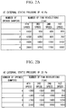
- a table of the format shown in Fig. 2A is stored in a storage area of the control unit 4. As shown in Fig. 2A , the table sets out the number of revolutions of the indoor fan 12 (hereinafter simply referred to as the "number of fan revolutions") to be instructed by the control unit 4. In the table, the number of fun revolutions (rpm) is set according to the number of opened dampers 6 and a set level of airflow of the indoor fan 12. In Fig. 2A , the airflow of the indoor fan 12 is set from four speeds (four setting levels), though two or more setting levels are only required.
- the number of fan revolutions increases as the speed changes from the first speed to the fourth speed.
- the number of fan revolutions also increases as the number of opened dampers 6 increases.
- the number of fan revolutions is increased with increase in the number of opened dampers 6, and this allows to maintain a flow speed of air-conditioned air blown from each air outlet 7.
- the table shown in Fig. 2A is prepared for each external static pressure, which corresponds to pressure loss of the duct 11.
- the table shown in Fig. 2A is prepared for an external static pressure of 10 Pa
- the table shown in Fig. 2B is prepared for an external static pressure of 20 Pa.
- the tables are prepared such that the number of fan revolutions increases with increase in the external static pressure. This allows to ensure desired airflow even when there is a high external static pressure in the installation environment. For example, the pressure loss when all dampers 6 are opened is used as the external static pressure.
- Plural tables shown in Figs. 2A and 2B are prepared according to the number of external static pressures of the duct 11 for which the indoor unit 3 is expected to be installed. After the indoor unit 3 is installed, an appropriate table is selected from the plural tables according to the status of external static pressure of the duct 11.
- the control unit 4 stores, in its storage area, the maximum number of revolutions of the compressor that is set for each number of fan revolutions in the tables shown in Figs. 2A and 2B .
- the control unit 4 determines the number of revolutions of the compressor so as not to exceed the maximum number of revolutions.
- the control unit 4 regulates the number of revolutions of the compressor, an opening degree of the expansion valve and the number of revolutions of the indoor fan 12 to deliver a temperature set by the remote controller 10.
- the number of revolutions of the indoor fan 12 is determined based on the tables shown in Figs. 2A and 2B . That is, the number of fan revolutions is determined according to the number of opened dampers 6 grasped by the control unit 4 and the set level of airflow set by the remote controller 10.
- the control unit 4 When a measured temperature measured by the temperature sensor 9 reaches the set temperature, the control unit 4 instructs the dampers 6 to be closed and turns off the thermostat. When the measured temperature leaves a predetermined temperature range centered around the set temperature, the control unit 4 instructs the closed dampers 6 to be opened and turns on the thermostat. When the number of opened dampers 6 is changed in this way, the control unit 4 changes the number of revolutions of the indoor fan 12 with reference to the table.
- control unit 4 When the dampers 6 are opened or closed in response to the user's operation on the on-off terminal 8, the control unit 4 reacquires the number of opened dampers 6 and resets the number of fan revolutions based on the table.
- the present embodiment provides the following functions and effects.
- the control unit 4 includes the table that sets out the number of revolutions of the indoor fan 12 according to the number of opened dampers 6. This allows to maintain a flow speed of air-conditioned air blown into the air-conditioning area 5, regardless of pressure loss due to opening and closing of the dampers 6. Further, the number of revolutions of the indoor fan 12 is set according to the set level of airflow of the indoor fan 12. This allows for air-conditioning without any complicated control such as capacity control of the compressor.
- each air-conditioning area 5 is provided with the on-off terminal 8 to open and close the damper 6, the user can open or close the damper 6 on his/her own choice by operating the on-off terminal 8.
- the control unit 4 acquires the status of the dampers 6 opened or closed by each on-off terminal 8 and thereby determines the number of opened dampers 6. This allows for simple control by setting the appropriate number of revolutions of the indoor fan 12 based on the table, even when the user forcibly opens or closes the damper 6.
- Each air-conditioning area 5 is provided with the temperature sensor 9, and the control unit 4 opens and closes the dampers 6 based on the measured temperature from the temperature sensor 9. Specifically, when the measured temperature from the temperature sensor 9 reaches a set temperature, the control unit 4 closes the opened dampers 6 and turns off the thermostat, and when the measured temperature leaves a predetermined temperature range centered around the set temperature, the control unit 4 opens the closed dampers 6 and turns on the thermostat.
- the control unit 4 determines the number of opened dampers 6. This allows for simple control by setting the appropriate number of revolutions of the indoor fan 12 based on the table, even when the dampers 6 are opened and closed according to the measured temperature from the temperature sensor 9.
- the maximum number of revolutions of the compressor is set according to the number of revolutions of the indoor fan 12. This prevents an excessive increase in the number of revolutions of the compressor, reducing energy consumption.
Landscapes
- Engineering & Computer Science (AREA)
- Physics & Mathematics (AREA)
- Fluid Mechanics (AREA)
- Chemical & Material Sciences (AREA)
- Combustion & Propulsion (AREA)
- Mechanical Engineering (AREA)
- General Engineering & Computer Science (AREA)
- Air Conditioning Control Device (AREA)
Abstract
Provided is an air conditioner that allows to maintain a flow speed of air-conditioned air blown into each air-conditioning area with simple control. The air conditioner includes: an indoor unit 3 connected to plural ducts 11 respectively opening to plural air-conditioning areas 5; an indoor fan 12 provided to the indoor unit 3 and sending air-conditioned air toward the plural ducts 11; plural dampers 6 respectively provided to the plural ducts 11 and operative to be opened and closed; and a control unit 4 configured to control the number of revolutions of the indoor fan 12 and opening and closing of the plural dampers 6. The control unit 4 includes a table that sets out the number of revolutions of the indoor fan 12 according to the number of opened dampers 6 and a set level of airflow of the indoor fan 12.
Description
- The present invention relates to an air conditioner including plural ducts respectively opening to plural air-conditioning areas and a method for controlling the air conditioner.
- There is known a duct type air conditioner that includes plural ducts respectively opening to plural air-conditioning areas. The plural ducts are connected to one indoor unit, and an indoor fan provided to the indoor unit distributes air-conditioned air to each duct (for example, see Patent Literature 1).
-
Patent Literature 1 discloses adjusting a temperature of each room to a set temperature by controlling a capacity of a capacity-variable compressor according to the total number of air outlets of rooms to which the air-conditioned air is actually supplied. - [PTL 1]
Japanese Unexamined Patent Application, Publication No.2013-200089 - However, controlling a capacity of a compressor as in
Patent Literature 1 has a drawback in that it not only requires various sensors but also involves complicated control, which incurs a large cost. - Further, when the total number of air outlets is changed by opening and closing the dampers during operation, a flow speed of air-conditioned air blown from each air outlet changes, which makes airflow unstable. This in turn makes it difficult to maintain a temperature of each air-conditioning area at a set temperature, and may eventually lead to wasteful energy consumption.
- The present invention has been made in view of such circumstances, and aims to provide an air conditioner and a method for controlling the air conditioner each of which allows to maintain a flow speed of air-conditioned air blown into each air-conditioning area with simple control.
- According to an aspect of the present invention, there is provided an air conditioner including: an indoor unit connected to plural ducts respectively opening to plural air-conditioning areas; an indoor fan provided to the indoor unit, the indoor fan sending air-conditioned air toward the plural ducts; plural dampers respectively provided to the plural ducts, the plural dampers being operative to be opened and closed; and a control unit configured to control a number of revolutions of the indoor fan and opening and closing of the plural dampers, wherein the control unit includes a table that sets out the number of revolutions of the indoor fan according to a number of opened dampers and a set level of airflow of the indoor fan.
- The control unit includes a table that sets out the number of revolutions of the indoor fan according to the number of opened dampers. This allows to maintain a flow speed of air-conditioned air blown into the air-conditioning area, regardless of pressure loss due to opening and closing of the dampers. Further, the number of revolutions of the indoor fan is set according to a set level of airflow of the indoor fan. This allows for air-conditioning without any complicated control such as capacity control of the compressor.
- The airflow of the indoor fan may be selected from two or more, e.g., four, setting levels.
- Further, in the air conditioner according to the above aspect of the present invention, each of the plural air-conditioning areas is provided with a switch to open and close a corresponding one of the plural dampers, and the control unit is configured to determine the number of opened dampers according to an opening and closing state of each of the plural dampers made by the switch.
- Each air-conditioning area is provided with a switch to open and close the damper. A user can open or close the damper on his/her own choice by operating the switch. The control unit acquires the status of dampers opened or closed by each switch and thereby determines the number of opened dampers. This allows for simple control by setting the appropriate number of revolutions of the indoor fan based on the table, even when the user forcibly opens or closes the damper.
- Further, in the air conditioner according to the above aspect of the present invention, each of the plural air-conditioning areas is provided with a temperature sensor to measure a temperature of the each of the plural air-conditioning areas, and the control unit is configured to open and close the plural dampers based on a measured temperature from the temperature sensor and determines the number of opened dampers.
- Each air-conditioning area is provided with a temperature sensor to measure a temperature of the air-conditioning area, and the control unit opens and closes the dampers based on the measured temperature from the temperature sensor. Specifically, when the measured temperature from the temperature sensor reaches a set temperature, the control unit closes the opened dampers and turns off the thermostat, and when the measured temperature leaves a predetermined temperature range centered around the set temperature, the control unit opens the closed dampers and turns on the thermostat.
- The control unit then determines the number of opened dampers. This allows for simple control by setting the appropriate number of revolutions of the indoor fan based on the table, even when the dampers are opened and closed according to the measured temperature from the temperature sensor.
- Further, in the air conditioner according to the above aspect of the present invention, the table includes plural tables according to pressure loss of the plural ducts.
- Since an appropriate number of revolutions of the indoor fan varies depending on pressure loss of the duct, plural tables are prepared according to pressure loss of the duct. This ensures the appropriate number of revolutions of the indoor fan.
- For example, pressure loss when all dampers are opened is used as the pressure loss of the duct.
- Further, in the air conditioner according to the above aspect of the present invention, the air conditioner includes a compressor to compress refrigerant, and the control unit stores a maximum number of revolutions of the compressor for each number of revolutions of the indoor fan set out in the table.
- The maximum number of revolutions of the compressor is set according to the number of revolutions of the indoor fan. This prevents an excessive increase in the number of revolutions of the compressor, reducing energy consumption.
- According to another aspect of the present invention, there is provided a method for controlling an air-conditioner including: an indoor unit connected to plural ducts respectively opening to plural air-conditioning areas; an indoor fan provided to the indoor unit, the indoor fan sending air-conditioned air toward the plural ducts; and plural dampers respectively provided to the plural ducts, the plural dampers being operative to be opened and closed, the air conditioner controlling a number of revolutions of the indoor fan and opening and closing of the plural dampers, and the method includes controlling the number of revolutions of the indoor fan based on a table that sets out the number of revolutions of the indoor fan according to a number of opened dampers and a set level of airflow of the indoor fan.
- The control unit includes the table that sets out the number of revolutions of the indoor fan according to the number of opened dampers and a set level of airflow of the indoor fan. This allows to maintain a flow speed of air-conditioned air blown into each air-conditioning area without any complicated control.
-
- [
Fig. 1 ]
Fig. 1 is a schematic configuration diagram of an air conditioner according to an embodiment of the present invention. - [
Fig. 2A ]
Fig. 2A is a table showing the numbers of fan revolutions. - [
Fig. 2B ]
Fig. 2B is a table showing the numbers of fan revolutions at a different external static pressure from that ofFig. 2A . - An embodiment of the present invention will be explained below with reference to the drawings.
-
Fig. 1 illustrates a ducttype air conditioner 1. - The
air conditioner 1 includes an outdoor unit (not shown in the figure) and anindoor unit 3. - The outdoor unit is provided with a compressor and an outdoor heat exchanger (both not shown in the figure). The
indoor unit 3 is provided with anindoor heat exchanger 13 and an expansion valve (not shown in the figure). The compressor, the outdoor heat exchanger, the expansion valve and theindoor heat exchanger 13 are connected with a refrigerant circuit in which refrigerant is circulated. The compressor is operative with its number of revolutions varied according to an instruction from acontrol unit 4. - The
indoor unit 3 is provided withindoor fans 12. Eachindoor fan 12 is, for example, a centrifugal multiblade fan and driven by adriving motor 14. The number of revolutions of eachindoor fan 12, more specifically the number of revolutions of the drivingmotor 14 is controlled by thecontrol unit 4. - A
duct 11 is connected to theindoor unit 3. With an upstream end of theduct 11 connected to oneindoor unit 3, theduct 11 is split into plural branch ducts. Thebranch ducts 11 are respectively connected to plural air-conditioning areas 5. Eachduct 11 is provided with anair outlet 7 at its downstream end. - Each
duct 11 is provided with adamper 6 to open and close an airflow path. Thedamper 6 is opened and closed according to an instruction from thecontrol unit 4. Each air-conditioning area 5 is provided with an on-offterminal 8 as a switch to open and close thedamper 6. The on-offterminal 8 is connected to thecontrol unit 4 and operable by a user. - Each air-
conditioning area 5 is provided with atemperature sensor 9. Output from thetemperature sensor 9 is transmitted to thecontrol unit 4. - A
remote controller 10, which is for example a wired remote controller, is connected to thecontrol unit 4. Temperature, timer and other settings can be made through theremote controller 10. - The
control unit 4 is composed of, for example, a central processing unit (CPU), a random access memory (RAM), a read-only memory (ROM), a computer-readable storage medium and other components. A series of processing to provide various functions is, for example, stored in a storage medium or the like in the form of a program. The CPU loads this program onto the RAM or the like to perform information processing and calculations, whereby various functions are provided. The program may be preinstalled in the ROM or another storage medium, may be provided by being stored in the computer-readable storage medium, or may be distributed via wired or wireless communication means. Examples of the computer-readable storage medium include a magnetic disk, a magnetooptical disk, CD-ROM, DVD-ROM and a semiconductor memory. - A table of the format shown in
Fig. 2A is stored in a storage area of thecontrol unit 4. As shown inFig. 2A , the table sets out the number of revolutions of the indoor fan 12 (hereinafter simply referred to as the "number of fan revolutions") to be instructed by thecontrol unit 4. In the table, the number of fun revolutions (rpm) is set according to the number of openeddampers 6 and a set level of airflow of theindoor fan 12. InFig. 2A , the airflow of theindoor fan 12 is set from four speeds (four setting levels), though two or more setting levels are only required. - The number of fan revolutions increases as the speed changes from the first speed to the fourth speed. The number of fan revolutions also increases as the number of opened
dampers 6 increases. The number of fan revolutions is increased with increase in the number of openeddampers 6, and this allows to maintain a flow speed of air-conditioned air blown from eachair outlet 7. - The table shown in
Fig. 2A is prepared for each external static pressure, which corresponds to pressure loss of theduct 11. For example, the table shown inFig. 2A is prepared for an external static pressure of 10 Pa, while the table shown inFig. 2B is prepared for an external static pressure of 20 Pa. The tables are prepared such that the number of fan revolutions increases with increase in the external static pressure. This allows to ensure desired airflow even when there is a high external static pressure in the installation environment. For example, the pressure loss when alldampers 6 are opened is used as the external static pressure. - Plural tables shown in
Figs. 2A and 2B are prepared according to the number of external static pressures of theduct 11 for which theindoor unit 3 is expected to be installed. After theindoor unit 3 is installed, an appropriate table is selected from the plural tables according to the status of external static pressure of theduct 11. - The
control unit 4 stores, in its storage area, the maximum number of revolutions of the compressor that is set for each number of fan revolutions in the tables shown inFigs. 2A and 2B . Thecontrol unit 4 determines the number of revolutions of the compressor so as not to exceed the maximum number of revolutions. - Then, control of the
air conditioner 1 configured as above will be explained. - The
control unit 4 regulates the number of revolutions of the compressor, an opening degree of the expansion valve and the number of revolutions of theindoor fan 12 to deliver a temperature set by theremote controller 10. The number of revolutions of theindoor fan 12 is determined based on the tables shown inFigs. 2A and 2B . That is, the number of fan revolutions is determined according to the number of openeddampers 6 grasped by thecontrol unit 4 and the set level of airflow set by theremote controller 10. - When a measured temperature measured by the
temperature sensor 9 reaches the set temperature, thecontrol unit 4 instructs thedampers 6 to be closed and turns off the thermostat. When the measured temperature leaves a predetermined temperature range centered around the set temperature, thecontrol unit 4 instructs theclosed dampers 6 to be opened and turns on the thermostat. When the number of openeddampers 6 is changed in this way, thecontrol unit 4 changes the number of revolutions of theindoor fan 12 with reference to the table. - When the
dampers 6 are opened or closed in response to the user's operation on the on-offterminal 8, thecontrol unit 4 reacquires the number of openeddampers 6 and resets the number of fan revolutions based on the table. - As described above, the present embodiment provides the following functions and effects.
- The
control unit 4 includes the table that sets out the number of revolutions of theindoor fan 12 according to the number of openeddampers 6. This allows to maintain a flow speed of air-conditioned air blown into the air-conditioning area 5, regardless of pressure loss due to opening and closing of thedampers 6. Further, the number of revolutions of theindoor fan 12 is set according to the set level of airflow of theindoor fan 12. This allows for air-conditioning without any complicated control such as capacity control of the compressor. - Since each air-
conditioning area 5 is provided with the on-offterminal 8 to open and close thedamper 6, the user can open or close thedamper 6 on his/her own choice by operating the on-offterminal 8. Thecontrol unit 4 acquires the status of thedampers 6 opened or closed by each on-offterminal 8 and thereby determines the number of openeddampers 6. This allows for simple control by setting the appropriate number of revolutions of theindoor fan 12 based on the table, even when the user forcibly opens or closes thedamper 6. - Each air-
conditioning area 5 is provided with thetemperature sensor 9, and thecontrol unit 4 opens and closes thedampers 6 based on the measured temperature from thetemperature sensor 9. Specifically, when the measured temperature from thetemperature sensor 9 reaches a set temperature, thecontrol unit 4 closes the openeddampers 6 and turns off the thermostat, and when the measured temperature leaves a predetermined temperature range centered around the set temperature, thecontrol unit 4 opens theclosed dampers 6 and turns on the thermostat. - The
control unit 4 then determines the number of openeddampers 6. This allows for simple control by setting the appropriate number of revolutions of theindoor fan 12 based on the table, even when thedampers 6 are opened and closed according to the measured temperature from thetemperature sensor 9. - Since an appropriate number of revolutions of the
indoor fan 12 varies depending on pressure loss (external static pressure) of theduct 11, plural tables are prepared according to pressure loss of theduct 11. This ensures the appropriate number of revolutions of theindoor fan 12. - The maximum number of revolutions of the compressor is set according to the number of revolutions of the
indoor fan 12. This prevents an excessive increase in the number of revolutions of the compressor, reducing energy consumption. -
- 1
- Air conditioner
- 3
- Indoor unit
- 4
- Control unit
- 5
- Air-conditioning area
- 6
- Damper
- 7
- Air outlet
- 8
- On-off terminal
- 9
- Temperature sensor
- 10
- Remote controller
- 11
- Duct
- 12
- Indoor fan
- 13
- Indoor heat exchanger
- 14
- Driving motor
Claims (6)
- An air conditioner comprising:an indoor unit connected to a plurality of ducts respectively opening to a plurality of air-conditioning areas;an indoor fan provided to the indoor unit, the indoor fan sending air-conditioned air toward the plurality of ducts;a plurality of dampers respectively provided to the plurality of ducts, the plurality of dampers being operative to be opened and closed; anda control unit configured to control a number of revolutions of the indoor fan and opening and closing of the plurality of dampers, whereinthe control unit includes a table that sets out the number of revolutions of the indoor fan according to a number of opened dampers and a set level of airflow of the indoor fan.
- The air conditioner according to claim 1, wherein
each of the plurality of air-conditioning areas is provided with a switch to open and close a corresponding one of the plurality of dampers, and
the control unit is configured to determine the number of opened dampers according to an opening and closing state of each of the plurality of dampers made by the switch. - The air conditioner according to claim 1 or 2, wherein
each of the plurality of air-conditioning areas is provided with a temperature sensor to measure a temperature of the each of the plurality of air-conditioning areas, and
the control unit is configured to open and close the plurality of dampers based on a measured temperature from the temperature sensor and determines the number of opened dampers. - The air conditioner according to any one of claims 1 to 3, wherein
the table comprises a plurality of tables according to pressure loss of the plurality of ducts. - The air conditioner according to any one of claims 1 to 4, wherein
the air conditioner comprises a compressor to compress refrigerant, and
the control unit stores a maximum number of revolutions of the compressor for each number of revolutions of the indoor fan set out in the table. - A method for controlling an air conditioner including: an indoor unit connected to a plurality of ducts respectively opening to a plurality of air-conditioning areas; an indoor fan provided to the indoor unit, the indoor fan sending air-conditioned air toward the plurality of ducts; and a plurality of dampers respectively provided to the plurality of ducts, the plurality of dampers being operative to be opened and closed, the air conditioner controlling a number of revolutions of the indoor fan and opening and closing of the plurality of dampers, the method comprising:controlling the number of revolutions of the indoor fan based on a table that sets out the number of revolutions of the indoor fan according to a number of opened dampers and a set level of airflow of the indoor fan.
Applications Claiming Priority (1)
| Application Number | Priority Date | Filing Date | Title |
|---|---|---|---|
| JP2017254120A JP2019120434A (en) | 2017-12-28 | 2017-12-28 | Air conditioner and controlling method of the same |
Publications (1)
| Publication Number | Publication Date |
|---|---|
| EP3505835A1 true EP3505835A1 (en) | 2019-07-03 |
Family
ID=64755308
Family Applications (1)
| Application Number | Title | Priority Date | Filing Date |
|---|---|---|---|
| EP18214923.7A Withdrawn EP3505835A1 (en) | 2017-12-28 | 2018-12-20 | Air conditioner and method for controlling the same |
Country Status (3)
| Country | Link |
|---|---|
| EP (1) | EP3505835A1 (en) |
| JP (1) | JP2019120434A (en) |
| AU (1) | AU2018282402A1 (en) |
Cited By (3)
| Publication number | Priority date | Publication date | Assignee | Title |
|---|---|---|---|---|
| CN112254310A (en) * | 2020-10-10 | 2021-01-22 | 广州市夸特电气自动化有限公司 | Digital intelligent fresh air valve and control method thereof |
| CN113091267A (en) * | 2021-04-16 | 2021-07-09 | 海信(广东)空调有限公司 | Control method of air conditioner |
| CN115200182A (en) * | 2022-05-18 | 2022-10-18 | 宁波奥克斯电气股份有限公司 | High-pressure control method and device of multi-connected air conditioner and multi-connected air conditioner |
Families Citing this family (2)
| Publication number | Priority date | Publication date | Assignee | Title |
|---|---|---|---|---|
| CN110440407B (en) * | 2019-08-07 | 2020-10-02 | 珠海格力电器股份有限公司 | Area control method and device |
| CN119573218B (en) * | 2024-12-25 | 2025-10-17 | 珠海格力电器股份有限公司 | Control method and control device of air conditioner, storage medium and air conditioner |
Citations (6)
| Publication number | Priority date | Publication date | Assignee | Title |
|---|---|---|---|---|
| US6719625B2 (en) * | 2001-09-26 | 2004-04-13 | Clifford Conrad Federspiel | Method and apparatus for controlling variable air volume supply fans in heating, ventilating, and air-conditioning systems |
| EP1605214A2 (en) * | 2004-05-21 | 2005-12-14 | Lg Electronics Inc. | Apparatus and method for controlling air-conditioner |
| KR20070107325A (en) * | 2006-05-02 | 2007-11-07 | 엘지전자 주식회사 | Air conditioner and control method of air conditioner |
| US20120037714A1 (en) * | 2009-05-13 | 2012-02-16 | Mitsubishi Electric Corporation | Air-conditioning apparatus |
| JP2013200089A (en) | 2012-03-26 | 2013-10-03 | Fujitsu General Ltd | Air conditioner |
| EP3059517A1 (en) * | 2014-11-19 | 2016-08-24 | Mitsubishi Electric Corporation | Duct-type air conditioning system |
Family Cites Families (4)
| Publication number | Priority date | Publication date | Assignee | Title |
|---|---|---|---|---|
| JPH04131655A (en) * | 1990-09-20 | 1992-05-06 | Kyodo Kogyo Kk | Centralized type air conditioning apparatus |
| JP4647503B2 (en) * | 2006-01-20 | 2011-03-09 | 東京電力株式会社 | Air conditioning system |
| JP2009030878A (en) * | 2007-07-27 | 2009-02-12 | Hitachi Appliances Inc | Air conditioner |
| JP4852635B2 (en) * | 2009-09-10 | 2012-01-11 | 株式会社長府製作所 | Air temperature controller fan control method and air temperature controller |
-
2017
- 2017-12-28 JP JP2017254120A patent/JP2019120434A/en active Pending
-
2018
- 2018-12-20 EP EP18214923.7A patent/EP3505835A1/en not_active Withdrawn
- 2018-12-20 AU AU2018282402A patent/AU2018282402A1/en not_active Abandoned
Patent Citations (6)
| Publication number | Priority date | Publication date | Assignee | Title |
|---|---|---|---|---|
| US6719625B2 (en) * | 2001-09-26 | 2004-04-13 | Clifford Conrad Federspiel | Method and apparatus for controlling variable air volume supply fans in heating, ventilating, and air-conditioning systems |
| EP1605214A2 (en) * | 2004-05-21 | 2005-12-14 | Lg Electronics Inc. | Apparatus and method for controlling air-conditioner |
| KR20070107325A (en) * | 2006-05-02 | 2007-11-07 | 엘지전자 주식회사 | Air conditioner and control method of air conditioner |
| US20120037714A1 (en) * | 2009-05-13 | 2012-02-16 | Mitsubishi Electric Corporation | Air-conditioning apparatus |
| JP2013200089A (en) | 2012-03-26 | 2013-10-03 | Fujitsu General Ltd | Air conditioner |
| EP3059517A1 (en) * | 2014-11-19 | 2016-08-24 | Mitsubishi Electric Corporation | Duct-type air conditioning system |
Cited By (4)
| Publication number | Priority date | Publication date | Assignee | Title |
|---|---|---|---|---|
| CN112254310A (en) * | 2020-10-10 | 2021-01-22 | 广州市夸特电气自动化有限公司 | Digital intelligent fresh air valve and control method thereof |
| CN113091267A (en) * | 2021-04-16 | 2021-07-09 | 海信(广东)空调有限公司 | Control method of air conditioner |
| CN115200182A (en) * | 2022-05-18 | 2022-10-18 | 宁波奥克斯电气股份有限公司 | High-pressure control method and device of multi-connected air conditioner and multi-connected air conditioner |
| CN115200182B (en) * | 2022-05-18 | 2023-03-21 | 宁波奥克斯电气股份有限公司 | High-pressure control method and device of multi-connected air conditioner and multi-connected air conditioner |
Also Published As
| Publication number | Publication date |
|---|---|
| AU2018282402A1 (en) | 2019-07-18 |
| JP2019120434A (en) | 2019-07-22 |
Similar Documents
| Publication | Publication Date | Title |
|---|---|---|
| AU2018282402A1 (en) | Air conditioner and method for controlling the same | |
| EP2527754A1 (en) | Control system and method for both energy saving and confort control in an air conditioning system | |
| US6386281B1 (en) | Air handler with return air bypass for improved dehumidification | |
| JP5404777B2 (en) | Air conditioner | |
| US4086781A (en) | Variable air volume air conditioning system | |
| US10359202B1 (en) | Air conditioning/heating airflow control method and system | |
| EP2607805A1 (en) | Outdoor-air treating air conditioner and multi-air conditioning system using same | |
| US20230204234A1 (en) | HVAC System With Volume Modulating Valve | |
| US10969123B2 (en) | Control of residential HVAC equipment for dehumidification | |
| KR20140056851A (en) | Air conditioner and method of controlling the same | |
| JP7041596B2 (en) | Air conditioning system | |
| CN116026006A (en) | Dehumidification control method of air conditioner and air conditioner | |
| JPWO2022195853A5 (en) | ||
| CN112752930A (en) | Air conditioner | |
| WO2017187480A1 (en) | Air conditioner | |
| JP2020165620A (en) | Air conditioner | |
| JPH0875231A (en) | Variable air conditioning system | |
| JP2912696B2 (en) | Air conditioner | |
| JPH03164647A (en) | air conditioner | |
| WO2016063437A1 (en) | Air conditioning apparatus | |
| CN113587396A (en) | Air conditioning system and control method thereof | |
| JP3103583B2 (en) | Air conditioner | |
| JP2013200089A (en) | Air conditioner | |
| JP2578885B2 (en) | Air conditioner | |
| JP2025063931A (en) | Air Conditioning System |
Legal Events
| Date | Code | Title | Description |
|---|---|---|---|
| PUAI | Public reference made under article 153(3) epc to a published international application that has entered the european phase |
Free format text: ORIGINAL CODE: 0009012 |
|
| AK | Designated contracting states |
Kind code of ref document: A1 Designated state(s): AL AT BE BG CH CY CZ DE DK EE ES FI FR GB GR HR HU IE IS IT LI LT LU LV MC MK MT NL NO PL PT RO RS SE SI SK SM TR |
|
| AX | Request for extension of the european patent |
Extension state: BA ME |
|
| STAA | Information on the status of an ep patent application or granted ep patent |
Free format text: STATUS: THE APPLICATION IS DEEMED TO BE WITHDRAWN |
|
| 18D | Application deemed to be withdrawn |
Effective date: 20200104 |