EP3505826A1 - Burner for a gas turbine power plant combustor, gas turbine power plant combustor comprising such a burner and a gas turbine power plant comprising such a combustor - Google Patents
Burner for a gas turbine power plant combustor, gas turbine power plant combustor comprising such a burner and a gas turbine power plant comprising such a combustor Download PDFInfo
- Publication number
- EP3505826A1 EP3505826A1 EP18215871.7A EP18215871A EP3505826A1 EP 3505826 A1 EP3505826 A1 EP 3505826A1 EP 18215871 A EP18215871 A EP 18215871A EP 3505826 A1 EP3505826 A1 EP 3505826A1
- Authority
- EP
- European Patent Office
- Prior art keywords
- burner
- combustor
- lance
- gas turbine
- casing
- Prior art date
- Legal status (The legal status is an assumption and is not a legal conclusion. Google has not performed a legal analysis and makes no representation as to the accuracy of the status listed.)
- Granted
Links
Images

Classifications
-
- F—MECHANICAL ENGINEERING; LIGHTING; HEATING; WEAPONS; BLASTING
- F02—COMBUSTION ENGINES; HOT-GAS OR COMBUSTION-PRODUCT ENGINE PLANTS
- F02C—GAS-TURBINE PLANTS; AIR INTAKES FOR JET-PROPULSION PLANTS; CONTROLLING FUEL SUPPLY IN AIR-BREATHING JET-PROPULSION PLANTS
- F02C7/00—Features, components parts, details or accessories, not provided for in, or of interest apart form groups F02C1/00 - F02C6/00; Air intakes for jet-propulsion plants
- F02C7/26—Starting; Ignition
- F02C7/264—Ignition
-
- F—MECHANICAL ENGINEERING; LIGHTING; HEATING; WEAPONS; BLASTING
- F23—COMBUSTION APPARATUS; COMBUSTION PROCESSES
- F23C—METHODS OR APPARATUS FOR COMBUSTION USING FLUID FUEL OR SOLID FUEL SUSPENDED IN A CARRIER GAS OR AIR
- F23C1/00—Combustion apparatus specially adapted for combustion of two or more kinds of fuel simultaneously or alternately, at least one kind of fuel being either a fluid fuel or a solid fuel suspended in a carrier gas or air
- F23C1/08—Combustion apparatus specially adapted for combustion of two or more kinds of fuel simultaneously or alternately, at least one kind of fuel being either a fluid fuel or a solid fuel suspended in a carrier gas or air liquid and gaseous fuel
-
- F—MECHANICAL ENGINEERING; LIGHTING; HEATING; WEAPONS; BLASTING
- F23—COMBUSTION APPARATUS; COMBUSTION PROCESSES
- F23D—BURNERS
- F23D14/00—Burners for combustion of a gas, e.g. of a gas stored under pressure as a liquid
- F23D14/02—Premix gas burners, i.e. in which gaseous fuel is mixed with combustion air upstream of the combustion zone
-
- F—MECHANICAL ENGINEERING; LIGHTING; HEATING; WEAPONS; BLASTING
- F23—COMBUSTION APPARATUS; COMBUSTION PROCESSES
- F23R—GENERATING COMBUSTION PRODUCTS OF HIGH PRESSURE OR HIGH VELOCITY, e.g. GAS-TURBINE COMBUSTION CHAMBERS
- F23R3/00—Continuous combustion chambers using liquid or gaseous fuel
- F23R3/28—Continuous combustion chambers using liquid or gaseous fuel characterised by the fuel supply
- F23R3/286—Continuous combustion chambers using liquid or gaseous fuel characterised by the fuel supply having fuel-air premixing devices
-
- F—MECHANICAL ENGINEERING; LIGHTING; HEATING; WEAPONS; BLASTING
- F23—COMBUSTION APPARATUS; COMBUSTION PROCESSES
- F23R—GENERATING COMBUSTION PRODUCTS OF HIGH PRESSURE OR HIGH VELOCITY, e.g. GAS-TURBINE COMBUSTION CHAMBERS
- F23R3/00—Continuous combustion chambers using liquid or gaseous fuel
- F23R3/28—Continuous combustion chambers using liquid or gaseous fuel characterised by the fuel supply
- F23R3/34—Feeding into different combustion zones
-
- F—MECHANICAL ENGINEERING; LIGHTING; HEATING; WEAPONS; BLASTING
- F23—COMBUSTION APPARATUS; COMBUSTION PROCESSES
- F23R—GENERATING COMBUSTION PRODUCTS OF HIGH PRESSURE OR HIGH VELOCITY, e.g. GAS-TURBINE COMBUSTION CHAMBERS
- F23R3/00—Continuous combustion chambers using liquid or gaseous fuel
- F23R3/28—Continuous combustion chambers using liquid or gaseous fuel characterised by the fuel supply
- F23R3/38—Continuous combustion chambers using liquid or gaseous fuel characterised by the fuel supply comprising rotary fuel injection means
-
- F—MECHANICAL ENGINEERING; LIGHTING; HEATING; WEAPONS; BLASTING
- F23—COMBUSTION APPARATUS; COMBUSTION PROCESSES
- F23R—GENERATING COMBUSTION PRODUCTS OF HIGH PRESSURE OR HIGH VELOCITY, e.g. GAS-TURBINE COMBUSTION CHAMBERS
- F23R3/00—Continuous combustion chambers using liquid or gaseous fuel
- F23R3/42—Continuous combustion chambers using liquid or gaseous fuel characterised by the arrangement or form of the flame tubes or combustion chambers
-
- F—MECHANICAL ENGINEERING; LIGHTING; HEATING; WEAPONS; BLASTING
- F23—COMBUSTION APPARATUS; COMBUSTION PROCESSES
- F23R—GENERATING COMBUSTION PRODUCTS OF HIGH PRESSURE OR HIGH VELOCITY, e.g. GAS-TURBINE COMBUSTION CHAMBERS
- F23R3/00—Continuous combustion chambers using liquid or gaseous fuel
- F23R3/42—Continuous combustion chambers using liquid or gaseous fuel characterised by the arrangement or form of the flame tubes or combustion chambers
- F23R3/58—Cyclone or vortex type combustion chambers
-
- F—MECHANICAL ENGINEERING; LIGHTING; HEATING; WEAPONS; BLASTING
- F23—COMBUSTION APPARATUS; COMBUSTION PROCESSES
- F23C—METHODS OR APPARATUS FOR COMBUSTION USING FLUID FUEL OR SOLID FUEL SUSPENDED IN A CARRIER GAS OR AIR
- F23C2900/00—Special features of, or arrangements for combustion apparatus using fluid fuels or solid fuels suspended in air; Combustion processes therefor
- F23C2900/07002—Premix burners with air inlet slots obtained between offset curved wall surfaces, e.g. double cone burners
-
- F—MECHANICAL ENGINEERING; LIGHTING; HEATING; WEAPONS; BLASTING
- F23—COMBUSTION APPARATUS; COMBUSTION PROCESSES
- F23C—METHODS OR APPARATUS FOR COMBUSTION USING FLUID FUEL OR SOLID FUEL SUSPENDED IN A CARRIER GAS OR AIR
- F23C2900/00—Special features of, or arrangements for combustion apparatus using fluid fuels or solid fuels suspended in air; Combustion processes therefor
- F23C2900/07021—Details of lances
-
- F—MECHANICAL ENGINEERING; LIGHTING; HEATING; WEAPONS; BLASTING
- F23—COMBUSTION APPARATUS; COMBUSTION PROCESSES
- F23D—BURNERS
- F23D2207/00—Ignition devices associated with burner
-
- F—MECHANICAL ENGINEERING; LIGHTING; HEATING; WEAPONS; BLASTING
- F23—COMBUSTION APPARATUS; COMBUSTION PROCESSES
- F23D—BURNERS
- F23D2900/00—Special features of, or arrangements for burners using fluid fuels or solid fuels suspended in a carrier gas
- F23D2900/00008—Burner assemblies with diffusion and premix modes, i.e. dual mode burners
-
- F—MECHANICAL ENGINEERING; LIGHTING; HEATING; WEAPONS; BLASTING
- F23—COMBUSTION APPARATUS; COMBUSTION PROCESSES
- F23R—GENERATING COMBUSTION PRODUCTS OF HIGH PRESSURE OR HIGH VELOCITY, e.g. GAS-TURBINE COMBUSTION CHAMBERS
- F23R2900/00—Special features of, or arrangements for continuous combustion chambers; Combustion processes therefor
- F23R2900/03341—Sequential combustion chambers or burners
Definitions
- the present invention relates to a burner for a gas turbine for power plants.
- the present invention relates to a premix burner for a sequential can combustor of a gas turbine for power plants.
- the present invention refers to a sequential can combustor comprising the above mentioned premix burner and to the gas turbine for power plants comprising such a sequential can combustor.
- a gas turbine assembly for power plants comprises a rotor having an axis and provided with an upstream compressor sector, a combustor sector and a downstream turbine sector.
- the terms downstream and upstream refer to the direction of the main gas flow passing through the gas turbine.
- the compressor comprises an inlet supplied with air and a plurality of blades compressing the passing air.
- the compressed air leaving the compressor flows into a plenum, i.e. a closed volume delimited by an outer casing, and from there into the combustor.
- the compressed air is mixed with at least one fuel.
- the mixture of fuel and compressed air flows into a combustion chamber where this mixture are combusted.
- the resulting hot gas leaves the combustor and is expanded in the turbine performing work on the rotor.
- a sequential gas turbine comprises two combustors in series wherein each combustor is provided with the relative burner and combustion chamber. Following the main gas flow direction, the upstream combustor is called “premix” combustor and is fed by the compressed air. The downstream combustor is called “sequential” or “reheat” combustor and is fed by the hot gas leaving the first combustion chamber.
- the two combustors are physically separated by a stage of turbine blades, called high pressure turbine.
- the sequential liner and the picture frame are realized as a single piece called transition duct configured for guiding the hot gas leaving the combustor towards the turbine, in particular towards the first vane of the turbine.
- the reheat burner can be realized in form of a plurality of single or dual fuel injector fingers extending across the flow channel.
- these injector fingers can be realized in form of a streamline body having preferably a lobed trailing edge. Due to the high hot gas temperature, the reheat burner is not provided with any sparker and the combustion starts as a self combustion.
- the premix burner in subsequent can combustor has a burner axis and comprises an inlet fed by compressed air and an outlet for discharging a mixture of air and fuel in a combustion chamber.
- the burner comprises at least a fuel injector, preferably a plurality of gas and/or oil injectors, configured for injecting fuel in the air flow passing through the burner.
- a swirl generator configured for generating an axial swirl flow of air or of a mixture of air and fuel entering in the combustion chamber.
- the burner comprises a casing, configured for limiting/containing the swirl flow and for being coupled with the combustor chamber casing, and an axial lance extending along the axis substantially up to the combustion chamber, i.e. substantially in axial flush with the burner outlet.
- This kind of lance is also called "bluff body".
- a lance is provided with any inner channels configured for guiding carrying air, oil fuel and/or gas fuel to the lance tip. From the lance tip, the oil and/or the gas fuel are injected in the swirl flow entering the combustion chamber.
- the zone over the lance tip, where the mixture air/fuel occurs, is called “bluff body recirculation zone", due to the fact that the lance is configured to realize a recirculation vortex breakdown at the lance tip.
- the combustor is provided with, at least, a spark generator, usually integrated in a particular lance called “torch”.
- the spark generator is arranged downstream the fuel injection, i.e. downstream the lance tip, at a first portion of the combustion chamber.
- the spark generator support torch is disposed radially with respect to the combustor axis. In order to reach the gas to be combusted, the torch passes through a hole obtained in several liner walls of the combustion chamber.
- the through holes obtained in the liner walls supporting the torch may generate hot gas leakages.
- the spark generator is located in the combustion chamber and therefore is in direct contact with the hot combustion gas. In this condition, the spark generator may be affected by oxidation.
- the liner walls supporting the torch are subjected to different temperature, for instance the inner liner hot shell is hotter than the outer liner cold shell. In this condition, a uneven axial displacement of the hole supporting the torch may occur with an undue wear of the liner walls.
- a primary object of the present invention is to provide a burner for a gas turbine power plant, in particular a burner for a can combustor of a gas turbine power plant.
- the burner according the present invention may be a premix burner for a sequential can combustor or the single burner present in a single stage can combustor.
- the burner according to the present invention may also be a burner of an annular combustor in a gas turbine provided with a high pressure turbine.
- the burner is cylindrical shaped and has an axis that also correspond to the main axial air/gas direction. Upstream with respect to the air flow direction, the burner comprises an inlet fed by compressed air, in particular compressed air delivered in the plenum by the compressor.
- the burner Downstream with respect to the air flow direction, the burner comprises a outlet facing a combustion chamber. Passing through the burner outlet, the gas leaves the burner and enters the combustion chamber.
- the burner according the invention is provided with a bluff body lance, i.e. a lance having a body extending along the burner axis and having a downstream portion, with a tip, substantially at the burner outlet and configured for realizing a recirculation zone for air and fuel mixture. In other words, along the axial direction the lance tip is substantial in flush with the inlet of the combustion chamber.
- the burner is also provided with at least a fuel injector, preferably a plurality of gas and/or oil fuel injectors, for injecting fuel in the air flow passing through the burner.
- the burner moreover comprises a casing surrounding the lance and forming an annular cavity at least around the lance downstream portion. Additionally, the burner comprises a swirl generator configured for generating an axial swirl flow in the annular cavity.
- the burner further comprises at least a spark generator at the lance tip. Therefore the spark generator is integrated in the lance and is axially facing the combustion chamber.
- the sparker at the lance tip provides a plurality of advantages with respect to the prior art practice wherein the torch is radially disposed in the combustion chamber downstream the lance tip. Indeed, according to the invention, the sparker is located in a flame stable zone and therefore enables reliable ignition conditions. The sparker is not arranged in the combustion chamber and therefore the risk of wear and oxidation is minimized. Moreover, the sparker needs only axial compensation in order to accommodate thermal expansions
- the swirl generator comprises a plurality of streamline bodies configured for swirling the compressed air passing through the annular cavity.
- These streamline bodies may be connected to the outer surface of the lance and/or to the inner surface of the casing.
- the fuel injectors may be located at the streamline bodies and/or at the lanced tip and/or at the outer casing.
- the casing or outer casing, comprises an intermediate portion configured for acting as a swirl generator for swirling the compressed air passing through the outer casing.
- the swirl portion of the casing is preferably V diverging shaped and is followed by a tubular or diffusion portion.
- the fuel injectors may be located at the V diverging shaped portion of the outer casing and/or at the lanced tip.
- the lance tip may be provided with carrying or cooling air injecting holes and along the axis the spark generator may be in flush with or recessed or protruding the lance tip surface.
- the lance tip may be provided with a temperature sensor and/or a pressure sensor and/or a flame sensor.
- the present invention refers also to the combustor, in particular a sequential can combustor provided with a premix burner as foregoing described, and to a gas turbine for power plants comprising such a can combustor.
- FIG. 1 is a schematic view of a gas turbine for power plants that can be provided with a burner according to the present invention.
- a gas turbine having an axis 9 and comprising a compressor 2, a combustor sector 4 and a turbine 3.
- the compressor comprises an inlet fed by ambient air that, once compressed, leaves the compressor 2 and enters in a plenum 16, i.e. a volume define by an outer casing 17.
- the compressed air 15 enters in the combustor sector that comprises a plurality of can combustors 4 annularly arranged around the axis 9.
- downstream and upstream refer to the gas main flow direction.
- Each can combustor 4 comprises at least a burner 5, where the compressed air is mixed with at least a fuel. This mixture is then combusted in a combustion chamber 6 and the resulting hot gas flows in a transition duct 7 downstream connected to the turbine 3.
- the turbine 3 comprises a plurality of vanes 12, i.e. stator blades, supported by a vane carrier 14, and a plurality of blades 13, i.e. rotor blades, supported by a rotor 8.
- the hot gas expands performing work on the rotor 8 and leaves the turbine 3 in form of exhaust gas 11.
- figure 2 is a schematic view of a can combustor that can be applied in the gas turbine of the figure 1 and that could be provided with a premix burner according to the present invention.
- figure 2 discloses a can combustor 4 having an axis 24 and comprising a combustor outer casing connected to a relative portal hole 28 of an outer casing 17 defining the plenum 16 where the compressed air is delivered by the compressor 2.
- the can combustor 4 comprises in series along the gas flow M a first combustor, or premix combustor 18, and a second combustor, or reheat combustor 19.
- the first combustor 18 comprises a first or premix burner 20 and a first combustion chamber 21.
- the reheat combustor 19 comprises a reheat burner 22 and a second combustion chamber 23.
- the fuel is fed to the reheat burner 22 by a fuel lance 25 axially extending through the first combustion chamber 21 up to the reheat burner 22.
- the can combustor 4 comprises a transition duct 26 for guiding the hot gas flow to the turbine 3.
- the present invention can be applied also in other kinds of sequential can combustors wherein the fuel is fed to the reheat burner 22 by pipes arranged outside the combustion chamber.
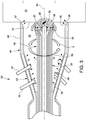
- FIG 3 is a schematic view of a burner according to a first embodiment of the invention.
- This burner 30 is called EV burner and comprises an axis 10 and a lance 35, or torch, extending long the axis 10 substantially up to the burner discharge outlet 33 connected to the combustion chamber 34.
- This burner 30 comprises a casing 41 surrounding the downstream portion 36 of the lance and defining an annular cavity 40 around the lance 35.
- the casing 41 and the lance 35 are realized as a single piece and are each other connected to an intermediate portion of the lance 35.
- the casing 41 comprises a V diverging portion 43 downstream followed by a tubular portion 46 connected to the combustion chamber 34.
- the casing 41 is provided with inlet ports for the compressed air (represented in figure 3 with the arrow 32) and this V diverging portion 43 is configured to generate an axial swirl S in the cavity 40 around the lance 35.
- the V diverging portion 43 is also provided with a plurality of fuel gas injecting holes 38 facing the cavity 40 connected to a gas supply channel obtained inside the casing 41.
- the downstream end 47 of the casing 41 may be provided with fuel gas injecting holes 38 and/or oil fuel injectors 39.
- the lance 35 may be provided with inner channels for feeding air 52, gas fuel 28 and oil fuel 39 to the lance tip 37 that is provided with relative injecting holes or injectors.
- the lance tip 37 is in a recessed position along the axial direction with respect to the casing end 47 and is provided with a sparker 45 protruding the lance tip surface towards the combustion chamber 34.
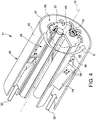
- FIG 4 is a schematic view of a second embodiment of the burner according to the invention.
- This burner 31 is called axial swirler burner and comprises an axis 10 and a lance 35, or torch, extending long the axis 10 substantially up to the burner discharge outlet 33 connected to the combustion chamber 34.
- This burner 31 comprises a tubular casing 42 with a downstream portion 46 surrounding the downstream portion 36 of the lance 35 and defining an annular cavity 40 around the lance 35.
- the outer surface of the lance 35 is provided with a plurality of streamline bodies 44 configured for generating an axial swirl S starting from an axial air feeding 32 in the cavity 40.
- the gas fuel injecting holes are obtained at the streamline bodies 44.
- the lance tip 37 is provided with two spark generators 45 protruding the lance tip surface towards the combustion chamber.
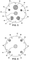
- the lance tip 37 is provided with two spark generators 45, an oil fuel injector 39, a flame sensor 50, a pressure sensor 49, a temperature sensor 48 and a plurality of gas fuel injecting holes 38.
- the lance tip 37 is provided with a spark generator 45, four oil fuel injectors 39 and a plurality of gas fuel injecting holes 38.
Landscapes
- Engineering & Computer Science (AREA)
- Chemical & Material Sciences (AREA)
- Combustion & Propulsion (AREA)
- Mechanical Engineering (AREA)
- General Engineering & Computer Science (AREA)
- Pre-Mixing And Non-Premixing Gas Burner (AREA)
- Pressure-Spray And Ultrasonic-Wave- Spray Burners (AREA)
Abstract
Description
- This application claims priority from Russian Patent Application No.
2017145773 filed on December 26, 2017 - The present invention relates to a burner for a gas turbine for power plants. In particular, the present invention relates to a premix burner for a sequential can combustor of a gas turbine for power plants.
- Moreover, the present invention refers to a sequential can combustor comprising the above mentioned premix burner and to the gas turbine for power plants comprising such a sequential can combustor.
- As known, a gas turbine assembly for power plants (in the following only gas turbine) comprises a rotor having an axis and provided with an upstream compressor sector, a combustor sector and a downstream turbine sector. The terms downstream and upstream refer to the direction of the main gas flow passing through the gas turbine. In particular, the compressor comprises an inlet supplied with air and a plurality of blades compressing the passing air. The compressed air leaving the compressor flows into a plenum, i.e. a closed volume delimited by an outer casing, and from there into the combustor. Inside the combustor, the compressed air is mixed with at least one fuel. The mixture of fuel and compressed air flows into a combustion chamber where this mixture are combusted. The resulting hot gas leaves the combustor and is expanded in the turbine performing work on the rotor.
- In order to achieve a high efficiency, a high turbine inlet temperature is required. However, due to this high temperature, high NOx emissions are generated.
- In order to reduce these emissions and to increase operational flexibility, today is known a particular kind of gas turbines performing a sequential combustion cycle.
- In general, a sequential gas turbine comprises two combustors in series wherein each combustor is provided with the relative burner and combustion chamber. Following the main gas flow direction, the upstream combustor is called "premix" combustor and is fed by the compressed air. The downstream combustor is called "sequential" or "reheat" combustor and is fed by the hot gas leaving the first combustion chamber. According to a first kind of sequential gas turbines, the two combustors are physically separated by a stage of turbine blades, called high pressure turbine.
- Today a second kind of sequential gas turbines is known wherein this kind of gas turbines is not provided with the high pressure turbine and the premix and the reheat burner are arranged directly one downstream the other inside a common can-shaped casing. According to this kind of sequential gas turbines, a plurality of can combustors are arranged as a ring around the rotor axis. Each can-combustor is provided with a liner, i.e. the casing limiting the combustion chambers, divided in two portions respectively upstream and downstream with respect to the reheat burner. The upstream portion of the liner is called premix liner whereas the downstream portion is called sequential liner and is downstream connected with a flange, called picture frame, facing the turbine. Usually, the sequential liner and the picture frame are realized as a single piece called transition duct configured for guiding the hot gas leaving the combustor towards the turbine, in particular towards the first vane of the turbine. For instance, the reheat burner can be realized in form of a plurality of single or dual fuel injector fingers extending across the flow channel. Preferably, these injector fingers can be realized in form of a streamline body having preferably a lobed trailing edge. Due to the high hot gas temperature, the reheat burner is not provided with any sparker and the combustion starts as a self combustion.
- Of course, it is possible to realize a can combustor with a single combustion stage and accordingly comprising a single burner and a single liner defining a single combustion chamber.
- The above-described different kinds of gas turbines, i.e. the can combustor with a single or two combustion stages, have been cited because the burner according to the present invention can be used as the single burner or as the premix burner in these two different kinds of can combustors.
- Usually the premix burner in subsequent can combustor, or the single burner in single can combustor, has a burner axis and comprises an inlet fed by compressed air and an outlet for discharging a mixture of air and fuel in a combustion chamber. The burner comprises at least a fuel injector, preferably a plurality of gas and/or oil injectors, configured for injecting fuel in the air flow passing through the burner. In order to have an improved mixing of the air with the fuel, it is known to provide the burner with a swirl generator, configured for generating an axial swirl flow of air or of a mixture of air and fuel entering in the combustion chamber. In particular, the burner comprises a casing, configured for limiting/containing the swirl flow and for being coupled with the combustor chamber casing, and an axial lance extending along the axis substantially up to the combustion chamber, i.e. substantially in axial flush with the burner outlet. This kind of lance is also called "bluff body". Preferably, such a lance is provided with any inner channels configured for guiding carrying air, oil fuel and/or gas fuel to the lance tip. From the lance tip, the oil and/or the gas fuel are injected in the swirl flow entering the combustion chamber. The zone over the lance tip, where the mixture air/fuel occurs, is called "bluff body recirculation zone", due to the fact that the lance is configured to realize a recirculation vortex breakdown at the lance tip. In order to start the combustion process in the combustion chamber, the combustor is provided with, at least, a spark generator, usually integrated in a particular lance called "torch".
- According to the prior art practice, the spark generator is arranged downstream the fuel injection, i.e. downstream the lance tip, at a first portion of the combustion chamber. In particular, in this arrangement, the spark generator support torch is disposed radially with respect to the combustor axis. In order to reach the gas to be combusted, the torch passes through a hole obtained in several liner walls of the combustion chamber.
- The above mentioned prior art disposition of the torch providing the spark generator involves some drawbacks. Indeed, the through holes obtained in the liner walls supporting the torch may generate hot gas leakages. Moreover, the spark generator is located in the combustion chamber and therefore is in direct contact with the hot combustion gas. In this condition, the spark generator may be affected by oxidation. Moreover, the liner walls supporting the torch are subjected to different temperature, for instance the inner liner hot shell is hotter than the outer liner cold shell. In this condition, a uneven axial displacement of the hole supporting the torch may occur with an undue wear of the liner walls.
- Starting from this prior art practice, there is today the need to improve the described burner with the central lance (bluff body) in order to overcome the foregoing mentioned drawbacks.
- A primary object of the present invention is to provide a burner for a gas turbine power plant, in particular a burner for a can combustor of a gas turbine power plant. The burner according the present invention may be a premix burner for a sequential can combustor or the single burner present in a single stage can combustor. However, the burner according to the present invention may also be a burner of an annular combustor in a gas turbine provided with a high pressure turbine. The burner is cylindrical shaped and has an axis that also correspond to the main axial air/gas direction. Upstream with respect to the air flow direction, the burner comprises an inlet fed by compressed air, in particular compressed air delivered in the plenum by the compressor. Downstream with respect to the air flow direction, the burner comprises a outlet facing a combustion chamber. Passing through the burner outlet, the gas leaves the burner and enters the combustion chamber. The burner according the invention is provided with a bluff body lance, i.e. a lance having a body extending along the burner axis and having a downstream portion, with a tip, substantially at the burner outlet and configured for realizing a recirculation zone for air and fuel mixture. In other words, along the axial direction the lance tip is substantial in flush with the inlet of the combustion chamber. The burner is also provided with at least a fuel injector, preferably a plurality of gas and/or oil fuel injectors, for injecting fuel in the air flow passing through the burner. The burner moreover comprises a casing surrounding the lance and forming an annular cavity at least around the lance downstream portion. Additionally, the burner comprises a swirl generator configured for generating an axial swirl flow in the annular cavity.
- The above listed burner features are known in state of the art and refer both to a burner having a tubular casing, called "axial swirler burner", or a V diverging casing, called "EV burner". A detailed description of these two different kinds of burners will be stated below with reference to
figures 3 and4 showing respectively a EV burner and a axial swirler burner. - According to the main aspect of the invention, the burner further comprises at least a spark generator at the lance tip. Therefore the spark generator is integrated in the lance and is axially facing the combustion chamber.
- Placing the sparker at the lance tip provides a plurality of advantages with respect to the prior art practice wherein the torch is radially disposed in the combustion chamber downstream the lance tip. Indeed, according to the invention, the sparker is located in a flame stable zone and therefore enables reliable ignition conditions. The sparker is not arranged in the combustion chamber and therefore the risk of wear and oxidation is minimized. Moreover, the sparker needs only axial compensation in order to accommodate thermal expansions
- According to a preferred embodiment of the invention, the swirl generator comprises a plurality of streamline bodies configured for swirling the compressed air passing through the annular cavity. These streamline bodies may be connected to the outer surface of the lance and/or to the inner surface of the casing. In this example, the fuel injectors may be located at the streamline bodies and/or at the lanced tip and/or at the outer casing.
- According to another preferred embodiment of the invention, the casing, or outer casing, comprises an intermediate portion configured for acting as a swirl generator for swirling the compressed air passing through the outer casing. The swirl portion of the casing is preferably V diverging shaped and is followed by a tubular or diffusion portion. In this example, the fuel injectors may be located at the V diverging shaped portion of the outer casing and/or at the lanced tip.
- Preferably, the lance tip may be provided with carrying or cooling air injecting holes and along the axis the spark generator may be in flush with or recessed or protruding the lance tip surface.
- Moreover, the lance tip may be provided with a temperature sensor and/or a pressure sensor and/or a flame sensor.
- The invention has been foregoing described as referring to the burner. However, the present invention refers also to the combustor, in particular a sequential can combustor provided with a premix burner as foregoing described, and to a gas turbine for power plants comprising such a can combustor.
- It is to be understood that both the foregoing general description and the following detailed description are exemplary, and are intended to provide further explanation of the invention as claimed. Other advantages and features of the invention will be apparent from the following description, drawings and claims.
- Further benefits and advantages of the present invention will become apparent after a careful reading of the detailed description with appropriate reference to the accompanying drawings.
- The invention itself, however, could be better understood by reference to the following detailed description of the invention, which describes an exemplary embodiment of the invention, taken in conjunction with the accompanying drawings, in which:
-
figure 1 is a schematic view of a gas turbine for power plants provided with a can combustor having a single combustion stage; -
figure 2 is a schematic view of a can combustor for a gas turbine for power plants provided in series with a premix and a reheat burner; -
figure 3 is an sectional view of a first embodiment according to the invention; -
figure 4 is a schematic view of a second embodiment according to the invention; -
figure 5 and 6 are schematic views of two examples of lance tips according to the invention; - In cooperation with the attached drawings, the technical contents and detailed description of the present invention are described thereinafter according to preferable embodiments, being not used to limit its executing scope. Any equivalent variation and modification made according to appended claims is all covered by the claims claimed by the present invention.
- Reference will now be made to the enclosed drawings to describe the present invention in detail.
- Reference is now made to
Fig. 1 that is a schematic view of a gas turbine for power plants that can be provided with a burner according to the present invention. In particular,figure 1 discloses agas turbine 1, having anaxis 9 and comprising acompressor 2, acombustor sector 4 and aturbine 3. As known, the compressor comprises an inlet fed by ambient air that, once compressed, leaves thecompressor 2 and enters in aplenum 16, i.e. a volume define by anouter casing 17. From theplenum 16, thecompressed air 15 enters in the combustor sector that comprises a plurality ofcan combustors 4 annularly arranged around theaxis 9. The terms downstream and upstream refer to the gas main flow direction. Each can combustor 4 comprises at least aburner 5, where the compressed air is mixed with at least a fuel. This mixture is then combusted in acombustion chamber 6 and the resulting hot gas flows in atransition duct 7 downstream connected to theturbine 3. Theturbine 3 comprises a plurality ofvanes 12, i.e. stator blades, supported by avane carrier 14, and a plurality ofblades 13, i.e. rotor blades, supported by arotor 8. In theturbine 3, the hot gas expands performing work on therotor 8 and leaves theturbine 3 in form ofexhaust gas 11. - Reference is now made to
figure 2 that is a schematic view of a can combustor that can be applied in the gas turbine of thefigure 1 and that could be provided with a premix burner according to the present invention. In particular,figure 2 discloses acan combustor 4 having anaxis 24 and comprising a combustor outer casing connected to a relativeportal hole 28 of anouter casing 17 defining theplenum 16 where the compressed air is delivered by thecompressor 2. Thecan combustor 4 comprises in series along the gas flow M a first combustor, orpremix combustor 18, and a second combustor, or reheatcombustor 19. In particular, thefirst combustor 18 comprises a first orpremix burner 20 and afirst combustion chamber 21. Thereheat combustor 19 comprises areheat burner 22 and asecond combustion chamber 23. According to the embodiment of thefigure 2 , the fuel is fed to thereheat burner 22 by afuel lance 25 axially extending through thefirst combustion chamber 21 up to thereheat burner 22. Downstream thesecond combustion chamber 23 thecan combustor 4 comprises atransition duct 26 for guiding the hot gas flow to theturbine 3. Of course, the present invention can be applied also in other kinds of sequential can combustors wherein the fuel is fed to thereheat burner 22 by pipes arranged outside the combustion chamber. - Reference is now made to
figure 3 that is a schematic view of a burner according to a first embodiment of the invention. Thisburner 30 is called EV burner and comprises anaxis 10 and alance 35, or torch, extending long theaxis 10 substantially up to theburner discharge outlet 33 connected to thecombustion chamber 34. Thisburner 30 comprises acasing 41 surrounding thedownstream portion 36 of the lance and defining anannular cavity 40 around thelance 35. In this example, thecasing 41 and thelance 35 are realized as a single piece and are each other connected to an intermediate portion of thelance 35. According to thefigure 3 , thecasing 41 comprises aV diverging portion 43 downstream followed by atubular portion 46 connected to thecombustion chamber 34. Along theV diverging portion 43 thecasing 41 is provided with inlet ports for the compressed air (represented infigure 3 with the arrow 32) and thisV diverging portion 43 is configured to generate an axial swirl S in thecavity 40 around thelance 35. TheV diverging portion 43 is also provided with a plurality of fuelgas injecting holes 38 facing thecavity 40 connected to a gas supply channel obtained inside thecasing 41. Alternatively, or in combination, also thedownstream end 47 of thecasing 41 may be provided with fuelgas injecting holes 38 and/oroil fuel injectors 39. Alternatively, or in combination, to the above mentioned fuel supply system, thelance 35 may be provided with inner channels for feedingair 52,gas fuel 28 andoil fuel 39 to thelance tip 37 that is provided with relative injecting holes or injectors. Thelance tip 37 is in a recessed position along the axial direction with respect to thecasing end 47 and is provided with asparker 45 protruding the lance tip surface towards thecombustion chamber 34. - Reference is now made to
figure 4 that is a schematic view of a second embodiment of the burner according to the invention. Thisburner 31 is called axial swirler burner and comprises anaxis 10 and alance 35, or torch, extending long theaxis 10 substantially up to theburner discharge outlet 33 connected to thecombustion chamber 34. Thisburner 31 comprises atubular casing 42 with adownstream portion 46 surrounding thedownstream portion 36 of thelance 35 and defining anannular cavity 40 around thelance 35. According tofigure 4 , the outer surface of thelance 35 is provided with a plurality ofstreamline bodies 44 configured for generating an axial swirl S starting from an axial air feeding 32 in thecavity 40. In this example, the gas fuel injecting holes are obtained at thestreamline bodies 44. Thelance tip 37 is provided with twospark generators 45 protruding the lance tip surface towards the combustion chamber. - Reference is now made to
figures 5 and 6 that are schematic views of two examples of lance tips according to the invention. In the example offigure 5 , thelance tip 37 is provided with twospark generators 45, anoil fuel injector 39, aflame sensor 50, apressure sensor 49, atemperature sensor 48 and a plurality of gas fuel injecting holes 38. In the example offigure 6 , thelance tip 37 is provided with aspark generator 45, fouroil fuel injectors 39 and a plurality of gas fuel injecting holes 38. - Although the invention has been explained in relation to its preferred embodiment(s) as mentioned above, it is to be understood that many other possible modifications and variations can be made without departing from the scope of the present invention. It is, therefore, contemplated that the appended claim or claims will cover such modifications and variations that fall within the scope of the invention.
Claims (10)
- A burner for a gas turbine power plant combustor (4), the burner (30, 31) having an axis (10) and comprising:- an inlet (32) fed by compressed air;- an outlet (33) facing a combustion chamber (34);- a bluff body lance (35) extending along the axis (10) and having a downstream portion (36) with a tip (37) substantially at the burner outlet (33);- at least a fuel injector (38, 39) for injecting fuel in the air flow;- an annular cavity (40) between at least the lance downstream portion (36) and a casing (41, 42);- a swirl generator (43, 44) for generating in the annular cavity (40) an axial swirl flow (S) of air or mixture air and fuel;characterized in that
the burner (30, 31) further comprises at least a spark generator (45) at the lance tip (37). - Burner as claimed in claim 1, wherein the swirl generator (43, 44) comprises a plurality of streamline bodies (44) configured for swirling the compressed air passing through the annular cavity (40), the streamline bodies (44) being connected to the outer surface of the lance (35) and/or to the inner surface of the casing (42).
- Burner as claimed in claim 1 or 2, wherein the casing (41) comprises an intermediate portion (43) configured for acting as a swirl generator for swirling the compressed air passing through the casing (41).
- Burner as claimed in any one of the foregoing claim wherein the casing (41, 42) comprises a downstream portion (46) connectable with the combustion chamber and having a tubular or a V diverging shape; along the axis (10) the lance tip (37) being in flush with or recessed or protruding the downstream edge (47) of the downstream portion (46) of the outer casing.
- Burner as claimed in any one of the foregoing claim wherein along the axis (10) the spark generator (15) is in flush with or recessed or protruding the lance tip (37).
- Burner as claimed in any one of the foregoing claim, wherein the fuel injector (38, 39) is arranged at the lance tip (37) and/or at the outer casing (41) facing the cavity (40) and/or at the connected to the swirl generator (44) facing the cavity (40).
- Burner as claimed in any one of the foregoing claim, wherein the fuel injector comprises at least a gas fuel injector (38) and/or at least an oil fuel injector (39).
- Burner as claimed in any one of the foregoing claim, wherein the lance tip (37) is provided with a temperature sensor (48) and/or a pressure sensor (49) and/or a flame sensor (50).
- Can combustor for a gas turbine (1), the can combustor (4) having an axis and comprising is series:- a first burner (5, 20);- a first combustion chamber (6, 21)- a second burner (22);- a second combustion chamber (23);- a transition duct (26);wherein the first burner (5, 20) is realized according to any one of the foregoing claims.
- A gas turbine for power plant; the gas turbine (1) having an axis (9) and comprising following the gas flow direction:- a compressor sector (2) for compressing ambient air,- a combustor sector (4) for mixing and combusting the compressed with at least a fuel- at least a turbine sector (3) for expanding the combusted hot gas flow leaving the combustors (4) and performing work on a rotor (8);wherein the combustor sector (4) comprises at least a can combustor according to claim 9.
Applications Claiming Priority (1)
| Application Number | Priority Date | Filing Date | Title |
|---|---|---|---|
| RU2017145773A RU2755240C2 (en) | 2017-12-26 | 2017-12-26 | Burner for combustion chamber of gas turbine power plant, combustion chamber of gas turbine power plant containing such burner, and gas turbine power plant containing such combustion chamber |
Publications (2)
| Publication Number | Publication Date |
|---|---|
| EP3505826A1 true EP3505826A1 (en) | 2019-07-03 |
| EP3505826B1 EP3505826B1 (en) | 2025-02-26 |
Family
ID=64901903
Family Applications (1)
| Application Number | Title | Priority Date | Filing Date |
|---|---|---|---|
| EP18215871.7A Active EP3505826B1 (en) | 2017-12-26 | 2018-12-24 | Combustor for a gas turbine and gas turbine for power plant comprising such a combustor |
Country Status (3)
| Country | Link |
|---|---|
| EP (1) | EP3505826B1 (en) |
| CN (1) | CN110030581B (en) |
| RU (1) | RU2755240C2 (en) |
Cited By (1)
| Publication number | Priority date | Publication date | Assignee | Title |
|---|---|---|---|---|
| EP4202306A1 (en) * | 2021-12-27 | 2023-06-28 | Ansaldo Energia Switzerland AG | Premix burner for a gas turbine assembly for power plant provided with a pilot lance suitable to be fed with common and highly reactive fuels, method for operating this burner and gas turbine assembly for power plant comprising this burner |
Families Citing this family (2)
| Publication number | Priority date | Publication date | Assignee | Title |
|---|---|---|---|---|
| EP3832091B1 (en) * | 2019-12-04 | 2023-06-14 | Ansaldo Energia Switzerland AG | Gas turbine assembly for power plant application fed by at least two different fuels (fuel-gas or fuel-oil) and a method for operating this assembly when switching fuels or when operating this assembly with fuel-oil |
| CN111895405B (en) * | 2020-07-23 | 2025-07-22 | 西安海镁特镁业有限公司 | Double-chamber gas burner |
Citations (3)
| Publication number | Priority date | Publication date | Assignee | Title |
|---|---|---|---|---|
| US20040045295A1 (en) * | 2002-09-11 | 2004-03-11 | Siemens Westinghouse Power Corporation | Flame-holding, single-mode nozzle assembly with tip cooling |
| US20120117976A1 (en) * | 2010-11-11 | 2012-05-17 | General Electric Company | Apparatus and method for igniting a combustor |
| US20140338342A1 (en) * | 2013-01-04 | 2014-11-20 | General Electric Company | Fuel injector having an ignitor for igniting a combustor of a gas turbine |
Family Cites Families (6)
| Publication number | Priority date | Publication date | Assignee | Title |
|---|---|---|---|---|
| DE10051221A1 (en) * | 2000-10-16 | 2002-07-11 | Alstom Switzerland Ltd | Burner with staged fuel injection |
| EP1389713A1 (en) * | 2002-08-12 | 2004-02-18 | ALSTOM (Switzerland) Ltd | Premixed exit ring pilot burner |
| WO2005095864A1 (en) * | 2004-03-31 | 2005-10-13 | Alstom Technology Ltd | Multiple burner arrangement for operating a combustion chamber, and method for operating the multiple burner arrangement |
| ES2576651T3 (en) * | 2009-01-15 | 2016-07-08 | Alstom Technology Ltd | Burner of a gas turbine |
| US9562692B2 (en) * | 2013-02-06 | 2017-02-07 | Siemens Aktiengesellschaft | Nozzle with multi-tube fuel passageway for gas turbine engines |
| EP3051206B1 (en) * | 2015-01-28 | 2019-10-30 | Ansaldo Energia Switzerland AG | Sequential gas turbine combustor arrangement with a mixer and a damper |
-
2017
- 2017-12-26 RU RU2017145773A patent/RU2755240C2/en active
-
2018
- 2018-12-24 CN CN201811579827.7A patent/CN110030581B/en active Active
- 2018-12-24 EP EP18215871.7A patent/EP3505826B1/en active Active
Patent Citations (3)
| Publication number | Priority date | Publication date | Assignee | Title |
|---|---|---|---|---|
| US20040045295A1 (en) * | 2002-09-11 | 2004-03-11 | Siemens Westinghouse Power Corporation | Flame-holding, single-mode nozzle assembly with tip cooling |
| US20120117976A1 (en) * | 2010-11-11 | 2012-05-17 | General Electric Company | Apparatus and method for igniting a combustor |
| US20140338342A1 (en) * | 2013-01-04 | 2014-11-20 | General Electric Company | Fuel injector having an ignitor for igniting a combustor of a gas turbine |
Cited By (1)
| Publication number | Priority date | Publication date | Assignee | Title |
|---|---|---|---|---|
| EP4202306A1 (en) * | 2021-12-27 | 2023-06-28 | Ansaldo Energia Switzerland AG | Premix burner for a gas turbine assembly for power plant provided with a pilot lance suitable to be fed with common and highly reactive fuels, method for operating this burner and gas turbine assembly for power plant comprising this burner |
Also Published As
| Publication number | Publication date |
|---|---|
| RU2017145773A (en) | 2019-06-26 |
| CN110030581A (en) | 2019-07-19 |
| RU2755240C2 (en) | 2021-09-14 |
| RU2017145773A3 (en) | 2021-03-04 |
| EP3505826B1 (en) | 2025-02-26 |
| CN110030581B (en) | 2022-05-13 |
Similar Documents
| Publication | Publication Date | Title |
|---|---|---|
| US12044180B2 (en) | Torch igniter for a combustor | |
| US9151500B2 (en) | System for supplying a fuel and a working fluid through a liner to a combustion chamber | |
| CN103375816B (en) | For supplying fuel to the system of burner | |
| EP3341656B1 (en) | Fuel nozzle assembly for a gas turbine | |
| EP4019841B1 (en) | Combustor nozzle for a gas turbine | |
| US20140352312A1 (en) | Injector for introducing a fuel-air mixture into a combustion chamber | |
| US20180149364A1 (en) | Combustor with axially staged fuel injection | |
| US11480339B2 (en) | Combustor for gas turbine and gas turbine having the same | |
| US11156362B2 (en) | Combustor with axially staged fuel injection | |
| US10240795B2 (en) | Pilot burner having burner face with radially offset recess | |
| US8745986B2 (en) | System and method of supplying fuel to a gas turbine | |
| CN106969379B (en) | Premix fuel nozzle assembly cartridge | |
| US20180372318A1 (en) | Combustor | |
| US11371709B2 (en) | Combustor air flow path | |
| EP3505826B1 (en) | Combustor for a gas turbine and gas turbine for power plant comprising such a combustor | |
| US9188337B2 (en) | System and method for supplying a working fluid to a combustor via a non-uniform distribution manifold | |
| US20060156734A1 (en) | Gas turbine combustor | |
| US20180340689A1 (en) | Low Profile Axially Staged Fuel Injector | |
| US10344978B2 (en) | Combustion liner cooling | |
| JP2019049254A (en) | Dual fuel fuel nozzle with gas fuel and liquid fuel functions | |
| US10746101B2 (en) | Annular fuel manifold with a deflector | |
| CN107191966B (en) | Combustion liner cooling | |
| JP2025116829A (en) | Fuel injection assembly for a combustor and axial fuel staging combustor including the fuel injection assembly - Patents.com |
Legal Events
| Date | Code | Title | Description |
|---|---|---|---|
| PUAI | Public reference made under article 153(3) epc to a published international application that has entered the european phase |
Free format text: ORIGINAL CODE: 0009012 |
|
| STAA | Information on the status of an ep patent application or granted ep patent |
Free format text: STATUS: THE APPLICATION HAS BEEN PUBLISHED |
|
| AK | Designated contracting states |
Kind code of ref document: A1 Designated state(s): AL AT BE BG CH CY CZ DE DK EE ES FI FR GB GR HR HU IE IS IT LI LT LU LV MC MK MT NL NO PL PT RO RS SE SI SK SM TR |
|
| AX | Request for extension of the european patent |
Extension state: BA ME |
|
| STAA | Information on the status of an ep patent application or granted ep patent |
Free format text: STATUS: REQUEST FOR EXAMINATION WAS MADE |
|
| 17P | Request for examination filed |
Effective date: 20191219 |
|
| RBV | Designated contracting states (corrected) |
Designated state(s): AL AT BE BG CH CY CZ DE DK EE ES FI FR GB GR HR HU IE IS IT LI LT LU LV MC MK MT NL NO PL PT RO RS SE SI SK SM TR |
|
| STAA | Information on the status of an ep patent application or granted ep patent |
Free format text: STATUS: EXAMINATION IS IN PROGRESS |
|
| 17Q | First examination report despatched |
Effective date: 20200312 |
|
| RAP3 | Party data changed (applicant data changed or rights of an application transferred) |
Owner name: ANSALDO ENERGIA SWITZERLAND AG |
|
| P01 | Opt-out of the competence of the unified patent court (upc) registered |
Effective date: 20240430 |
|
| GRAP | Despatch of communication of intention to grant a patent |
Free format text: ORIGINAL CODE: EPIDOSNIGR1 |
|
| STAA | Information on the status of an ep patent application or granted ep patent |
Free format text: STATUS: GRANT OF PATENT IS INTENDED |
|
| INTG | Intention to grant announced |
Effective date: 20240919 |
|
| GRAS | Grant fee paid |
Free format text: ORIGINAL CODE: EPIDOSNIGR3 |
|
| GRAA | (expected) grant |
Free format text: ORIGINAL CODE: 0009210 |
|
| STAA | Information on the status of an ep patent application or granted ep patent |
Free format text: STATUS: THE PATENT HAS BEEN GRANTED |
|
| AK | Designated contracting states |
Kind code of ref document: B1 Designated state(s): AL AT BE BG CH CY CZ DE DK EE ES FI FR GB GR HR HU IE IS IT LI LT LU LV MC MK MT NL NO PL PT RO RS SE SI SK SM TR |
|
| REG | Reference to a national code |
Ref country code: GB Ref legal event code: FG4D |
|
| REG | Reference to a national code |
Ref country code: CH Ref legal event code: EP |
|
| REG | Reference to a national code |
Ref country code: DE Ref legal event code: R096 Ref document number: 602018079542 Country of ref document: DE |
|
| REG | Reference to a national code |
Ref country code: IE Ref legal event code: FG4D |
|
| REG | Reference to a national code |
Ref country code: NL Ref legal event code: MP Effective date: 20250226 |
|
| PG25 | Lapsed in a contracting state [announced via postgrant information from national office to epo] |
Ref country code: RS Free format text: LAPSE BECAUSE OF FAILURE TO SUBMIT A TRANSLATION OF THE DESCRIPTION OR TO PAY THE FEE WITHIN THE PRESCRIBED TIME-LIMIT Effective date: 20250526 |
|
| PG25 | Lapsed in a contracting state [announced via postgrant information from national office to epo] |
Ref country code: FI Free format text: LAPSE BECAUSE OF FAILURE TO SUBMIT A TRANSLATION OF THE DESCRIPTION OR TO PAY THE FEE WITHIN THE PRESCRIBED TIME-LIMIT Effective date: 20250226 |
|
| PG25 | Lapsed in a contracting state [announced via postgrant information from national office to epo] |
Ref country code: PL Free format text: LAPSE BECAUSE OF FAILURE TO SUBMIT A TRANSLATION OF THE DESCRIPTION OR TO PAY THE FEE WITHIN THE PRESCRIBED TIME-LIMIT Effective date: 20250226 |
|
| PG25 | Lapsed in a contracting state [announced via postgrant information from national office to epo] |
Ref country code: ES Free format text: LAPSE BECAUSE OF FAILURE TO SUBMIT A TRANSLATION OF THE DESCRIPTION OR TO PAY THE FEE WITHIN THE PRESCRIBED TIME-LIMIT Effective date: 20250226 |
|
| REG | Reference to a national code |
Ref country code: LT Ref legal event code: MG9D |
|
| PG25 | Lapsed in a contracting state [announced via postgrant information from national office to epo] |
Ref country code: IS Free format text: LAPSE BECAUSE OF FAILURE TO SUBMIT A TRANSLATION OF THE DESCRIPTION OR TO PAY THE FEE WITHIN THE PRESCRIBED TIME-LIMIT Effective date: 20250626 Ref country code: NO Free format text: LAPSE BECAUSE OF FAILURE TO SUBMIT A TRANSLATION OF THE DESCRIPTION OR TO PAY THE FEE WITHIN THE PRESCRIBED TIME-LIMIT Effective date: 20250526 |
|
| PG25 | Lapsed in a contracting state [announced via postgrant information from national office to epo] |
Ref country code: NL Free format text: LAPSE BECAUSE OF FAILURE TO SUBMIT A TRANSLATION OF THE DESCRIPTION OR TO PAY THE FEE WITHIN THE PRESCRIBED TIME-LIMIT Effective date: 20250226 |
|
| PG25 | Lapsed in a contracting state [announced via postgrant information from national office to epo] |
Ref country code: HR Free format text: LAPSE BECAUSE OF FAILURE TO SUBMIT A TRANSLATION OF THE DESCRIPTION OR TO PAY THE FEE WITHIN THE PRESCRIBED TIME-LIMIT Effective date: 20250226 |
|
| PG25 | Lapsed in a contracting state [announced via postgrant information from national office to epo] |
Ref country code: PT Free format text: LAPSE BECAUSE OF FAILURE TO SUBMIT A TRANSLATION OF THE DESCRIPTION OR TO PAY THE FEE WITHIN THE PRESCRIBED TIME-LIMIT Effective date: 20250626 Ref country code: LV Free format text: LAPSE BECAUSE OF FAILURE TO SUBMIT A TRANSLATION OF THE DESCRIPTION OR TO PAY THE FEE WITHIN THE PRESCRIBED TIME-LIMIT Effective date: 20250226 |
|
| PG25 | Lapsed in a contracting state [announced via postgrant information from national office to epo] |
Ref country code: GR Free format text: LAPSE BECAUSE OF FAILURE TO SUBMIT A TRANSLATION OF THE DESCRIPTION OR TO PAY THE FEE WITHIN THE PRESCRIBED TIME-LIMIT Effective date: 20250527 Ref country code: BG Free format text: LAPSE BECAUSE OF FAILURE TO SUBMIT A TRANSLATION OF THE DESCRIPTION OR TO PAY THE FEE WITHIN THE PRESCRIBED TIME-LIMIT Effective date: 20250226 |
|
| REG | Reference to a national code |
Ref country code: AT Ref legal event code: MK05 Ref document number: 1770962 Country of ref document: AT Kind code of ref document: T Effective date: 20250226 |
|
| PG25 | Lapsed in a contracting state [announced via postgrant information from national office to epo] |
Ref country code: SE Free format text: LAPSE BECAUSE OF FAILURE TO SUBMIT A TRANSLATION OF THE DESCRIPTION OR TO PAY THE FEE WITHIN THE PRESCRIBED TIME-LIMIT Effective date: 20250226 |
|
| PG25 | Lapsed in a contracting state [announced via postgrant information from national office to epo] |
Ref country code: SM Free format text: LAPSE BECAUSE OF FAILURE TO SUBMIT A TRANSLATION OF THE DESCRIPTION OR TO PAY THE FEE WITHIN THE PRESCRIBED TIME-LIMIT Effective date: 20250226 |
|
| PG25 | Lapsed in a contracting state [announced via postgrant information from national office to epo] |
Ref country code: DK Free format text: LAPSE BECAUSE OF FAILURE TO SUBMIT A TRANSLATION OF THE DESCRIPTION OR TO PAY THE FEE WITHIN THE PRESCRIBED TIME-LIMIT Effective date: 20250226 |
|
| PG25 | Lapsed in a contracting state [announced via postgrant information from national office to epo] |
Ref country code: AT Free format text: LAPSE BECAUSE OF FAILURE TO SUBMIT A TRANSLATION OF THE DESCRIPTION OR TO PAY THE FEE WITHIN THE PRESCRIBED TIME-LIMIT Effective date: 20250226 |
|
| PG25 | Lapsed in a contracting state [announced via postgrant information from national office to epo] |
Ref country code: EE Free format text: LAPSE BECAUSE OF FAILURE TO SUBMIT A TRANSLATION OF THE DESCRIPTION OR TO PAY THE FEE WITHIN THE PRESCRIBED TIME-LIMIT Effective date: 20250226 Ref country code: CZ Free format text: LAPSE BECAUSE OF FAILURE TO SUBMIT A TRANSLATION OF THE DESCRIPTION OR TO PAY THE FEE WITHIN THE PRESCRIBED TIME-LIMIT Effective date: 20250226 |
|
| PG25 | Lapsed in a contracting state [announced via postgrant information from national office to epo] |
Ref country code: RO Free format text: LAPSE BECAUSE OF FAILURE TO SUBMIT A TRANSLATION OF THE DESCRIPTION OR TO PAY THE FEE WITHIN THE PRESCRIBED TIME-LIMIT Effective date: 20250226 |
|
| PG25 | Lapsed in a contracting state [announced via postgrant information from national office to epo] |
Ref country code: SK Free format text: LAPSE BECAUSE OF FAILURE TO SUBMIT A TRANSLATION OF THE DESCRIPTION OR TO PAY THE FEE WITHIN THE PRESCRIBED TIME-LIMIT Effective date: 20250226 |
|
| REG | Reference to a national code |
Ref country code: DE Ref legal event code: R097 Ref document number: 602018079542 Country of ref document: DE |
|
| PLBE | No opposition filed within time limit |
Free format text: ORIGINAL CODE: 0009261 |
|
| STAA | Information on the status of an ep patent application or granted ep patent |
Free format text: STATUS: NO OPPOSITION FILED WITHIN TIME LIMIT |
|
| REG | Reference to a national code |
Ref country code: CH Ref legal event code: L10 Free format text: ST27 STATUS EVENT CODE: U-0-0-L10-L00 (AS PROVIDED BY THE NATIONAL OFFICE) Effective date: 20260107 |
|
| 26N | No opposition filed |
Effective date: 20251127 |
|
| PGFP | Annual fee paid to national office [announced via postgrant information from national office to epo] |
Ref country code: DE Payment date: 20251222 Year of fee payment: 8 |
|
| PGFP | Annual fee paid to national office [announced via postgrant information from national office to epo] |
Ref country code: IT Payment date: 20251231 Year of fee payment: 8 |
|
| PG25 | Lapsed in a contracting state [announced via postgrant information from national office to epo] |
Ref country code: LT Free format text: LAPSE BECAUSE OF FAILURE TO SUBMIT A TRANSLATION OF THE DESCRIPTION OR TO PAY THE FEE WITHIN THE PRESCRIBED TIME-LIMIT Effective date: 20250226 |
|
| PG25 | Lapsed in a contracting state [announced via postgrant information from national office to epo] |
Ref country code: MC Free format text: LAPSE BECAUSE OF FAILURE TO SUBMIT A TRANSLATION OF THE DESCRIPTION OR TO PAY THE FEE WITHIN THE PRESCRIBED TIME-LIMIT Effective date: 20250226 |
|
| REG | Reference to a national code |
Ref country code: CH Ref legal event code: H13 Free format text: ST27 STATUS EVENT CODE: U-0-0-H10-H13 (AS PROVIDED BY THE NATIONAL OFFICE) Effective date: 20260723 |